WO2016151669A1 - 水処理装置 - Google Patents
水処理装置 Download PDFInfo
- Publication number
- WO2016151669A1 WO2016151669A1 PCT/JP2015/058436 JP2015058436W WO2016151669A1 WO 2016151669 A1 WO2016151669 A1 WO 2016151669A1 JP 2015058436 W JP2015058436 W JP 2015058436W WO 2016151669 A1 WO2016151669 A1 WO 2016151669A1
- Authority
- WO
- WIPO (PCT)
- Prior art keywords
- water
- primary
- unit
- concentrated water
- reflux
- Prior art date
- Legal status (The legal status is an assumption and is not a legal conclusion. Google has not performed a legal analysis and makes no representation as to the accuracy of the status listed.)
- Ceased
Links
Images


Classifications
-
- B—PERFORMING OPERATIONS; TRANSPORTING
- B01—PHYSICAL OR CHEMICAL PROCESSES OR APPARATUS IN GENERAL
- B01D—SEPARATION
- B01D61/00—Processes of separation using semi-permeable membranes, e.g. dialysis, osmosis or ultrafiltration; Apparatus, accessories or auxiliary operations specially adapted therefor
- B01D61/02—Reverse osmosis; Hyperfiltration ; Nanofiltration
- B01D61/12—Controlling or regulating
-
- B—PERFORMING OPERATIONS; TRANSPORTING
- B01—PHYSICAL OR CHEMICAL PROCESSES OR APPARATUS IN GENERAL
- B01D—SEPARATION
- B01D61/00—Processes of separation using semi-permeable membranes, e.g. dialysis, osmosis or ultrafiltration; Apparatus, accessories or auxiliary operations specially adapted therefor
- B01D61/02—Reverse osmosis; Hyperfiltration ; Nanofiltration
- B01D61/025—Reverse osmosis; Hyperfiltration
-
- B—PERFORMING OPERATIONS; TRANSPORTING
- B01—PHYSICAL OR CHEMICAL PROCESSES OR APPARATUS IN GENERAL
- B01D—SEPARATION
- B01D61/00—Processes of separation using semi-permeable membranes, e.g. dialysis, osmosis or ultrafiltration; Apparatus, accessories or auxiliary operations specially adapted therefor
- B01D61/02—Reverse osmosis; Hyperfiltration ; Nanofiltration
- B01D61/025—Reverse osmosis; Hyperfiltration
- B01D61/026—Reverse osmosis; Hyperfiltration comprising multiple reverse osmosis steps
-
- B—PERFORMING OPERATIONS; TRANSPORTING
- B01—PHYSICAL OR CHEMICAL PROCESSES OR APPARATUS IN GENERAL
- B01D—SEPARATION
- B01D61/00—Processes of separation using semi-permeable membranes, e.g. dialysis, osmosis or ultrafiltration; Apparatus, accessories or auxiliary operations specially adapted therefor
- B01D61/02—Reverse osmosis; Hyperfiltration ; Nanofiltration
- B01D61/08—Apparatus therefor
-
- C—CHEMISTRY; METALLURGY
- C02—TREATMENT OF WATER, WASTE WATER, SEWAGE, OR SLUDGE
- C02F—TREATMENT OF WATER, WASTE WATER, SEWAGE, OR SLUDGE
- C02F1/00—Treatment of water, waste water, or sewage
- C02F1/44—Treatment of water, waste water, or sewage by dialysis, osmosis or reverse osmosis
- C02F1/441—Treatment of water, waste water, or sewage by dialysis, osmosis or reverse osmosis by reverse osmosis
-
- B—PERFORMING OPERATIONS; TRANSPORTING
- B01—PHYSICAL OR CHEMICAL PROCESSES OR APPARATUS IN GENERAL
- B01D—SEPARATION
- B01D2311/00—Details relating to membrane separation process operations and control
- B01D2311/08—Specific process operations in the concentrate stream
-
- B—PERFORMING OPERATIONS; TRANSPORTING
- B01—PHYSICAL OR CHEMICAL PROCESSES OR APPARATUS IN GENERAL
- B01D—SEPARATION
- B01D2311/00—Details relating to membrane separation process operations and control
- B01D2311/25—Recirculation, recycling or bypass, e.g. recirculation of concentrate into the feed
-
- B—PERFORMING OPERATIONS; TRANSPORTING
- B01—PHYSICAL OR CHEMICAL PROCESSES OR APPARATUS IN GENERAL
- B01D—SEPARATION
- B01D2311/00—Details relating to membrane separation process operations and control
- B01D2311/25—Recirculation, recycling or bypass, e.g. recirculation of concentrate into the feed
- B01D2311/253—Bypassing of feed
- B01D2311/2532—Bypassing of feed to concentrate side
-
- B—PERFORMING OPERATIONS; TRANSPORTING
- B01—PHYSICAL OR CHEMICAL PROCESSES OR APPARATUS IN GENERAL
- B01D—SEPARATION
- B01D2317/00—Membrane module arrangements within a plant or an apparatus
- B01D2317/02—Elements in series
- B01D2317/027—Christmas tree arrangements
-
- B—PERFORMING OPERATIONS; TRANSPORTING
- B01—PHYSICAL OR CHEMICAL PROCESSES OR APPARATUS IN GENERAL
- B01D—SEPARATION
- B01D2317/00—Membrane module arrangements within a plant or an apparatus
- B01D2317/04—Elements in parallel
-
- C—CHEMISTRY; METALLURGY
- C02—TREATMENT OF WATER, WASTE WATER, SEWAGE, OR SLUDGE
- C02F—TREATMENT OF WATER, WASTE WATER, SEWAGE, OR SLUDGE
- C02F2103/00—Nature of the water, waste water, sewage or sludge to be treated
- C02F2103/08—Seawater, e.g. for desalination
-
- C—CHEMISTRY; METALLURGY
- C02—TREATMENT OF WATER, WASTE WATER, SEWAGE, OR SLUDGE
- C02F—TREATMENT OF WATER, WASTE WATER, SEWAGE, OR SLUDGE
- C02F2209/00—Controlling or monitoring parameters in water treatment
- C02F2209/02—Temperature
-
- C—CHEMISTRY; METALLURGY
- C02—TREATMENT OF WATER, WASTE WATER, SEWAGE, OR SLUDGE
- C02F—TREATMENT OF WATER, WASTE WATER, SEWAGE, OR SLUDGE
- C02F2209/00—Controlling or monitoring parameters in water treatment
- C02F2209/05—Conductivity or salinity
-
- C—CHEMISTRY; METALLURGY
- C02—TREATMENT OF WATER, WASTE WATER, SEWAGE, OR SLUDGE
- C02F—TREATMENT OF WATER, WASTE WATER, SEWAGE, OR SLUDGE
- C02F2301/00—General aspects of water treatment
- C02F2301/08—Multistage treatments, e.g. repetition of the same process step under different conditions
-
- Y—GENERAL TAGGING OF NEW TECHNOLOGICAL DEVELOPMENTS; GENERAL TAGGING OF CROSS-SECTIONAL TECHNOLOGIES SPANNING OVER SEVERAL SECTIONS OF THE IPC; TECHNICAL SUBJECTS COVERED BY FORMER USPC CROSS-REFERENCE ART COLLECTIONS [XRACs] AND DIGESTS
- Y02—TECHNOLOGIES OR APPLICATIONS FOR MITIGATION OR ADAPTATION AGAINST CLIMATE CHANGE
- Y02A—TECHNOLOGIES FOR ADAPTATION TO CLIMATE CHANGE
- Y02A20/00—Water conservation; Efficient water supply; Efficient water use
- Y02A20/124—Water desalination
- Y02A20/131—Reverse-osmosis
Definitions
- the present invention relates to a water treatment apparatus.
- Patent Document 1 Water treatment equipment using reverse osmosis membranes has been put into practical use as a technology for desalinating seawater and purifying industrial water.
- a technique described in Patent Document 1 below is known.
- the membrane treatment apparatus described in Patent Literature 1 is configured to supply raw water (covered water) to an upstream membrane module bank, a downstream membrane module bank, and an upstream membrane module bank each having a plurality of membrane modules. And a pump for pumping treated water).
- a target value is determined in advance with respect to the ratio of fresh water recovered from the treated water such as seawater (fresh water recovery rate).
- fresh water recovery rate is excessively high, the salt concentration contained in the concentrated water, which is the remaining component from which the fresh water is separated, is excessively increased.
- concentrated water with a high salt concentration is discharged into the environment, there is a concern that the environmental load will increase. For this reason, for example, when seawater is desalinated, the freshwater recovery rate is set to about 25 to 40%.
- the fresh water recovery rate relatively decreases.
- the supply pressure of the water to be treated to the reverse osmosis membrane can be increased by increasing the output of the pump. By increasing the pressure of the water to be treated, the amount of fresh water separated in the reverse osmosis membrane increases, and the fresh water recovery rate starts to increase.
- the apparatus described in Patent Document 1 As the fresh water recovery rate increases as described above, the amount of concentrated water separated from the treated water decreases. That is, in the apparatus described in Patent Document 1, the amount of concentrated water supplied from the upstream membrane module bank to the downstream membrane module bank is reduced. Furthermore, in a device using a reverse osmosis membrane, a lower limit is set for the amount (flow rate) of concentrated water discharged from one element. If the amount of concentrated water falls below this lower limit value, there is a possibility that problems such as scale deposition occur due to an increase in membrane surface concentration due to concentration polarization in the membrane module, and sufficient separation and concentration cannot be performed. Therefore, the apparatus described in Patent Document 1 has a limited fresh water recovery rate.
- This invention is made
- the water treatment apparatus is a reverse osmosis membrane apparatus that performs a process of separating the water to be treated supplied from the upstream side into primary concentrated water and fresh water, arranged in parallel with each other.
- a primary unit having a plurality of primary elements, a pump for supplying the water to be treated to the primary unit by pumping the water to be treated from the upstream side of the primary unit, and a smaller number than the primary elements are provided.
- a secondary unit having a secondary element as a reverse osmosis membrane device that is arranged in parallel with each other and performs a process of separating the primary concentrated water into secondary concentrated water and fresh water, and the secondary concentrated water A reflux part for refluxing a part between the primary unit and the secondary unit.
- the ratio (fresh water recovery rate) of fresh water recovered from the secondary unit to the deposition of the water to be processed increases.
- the secondary unit reduces the amount of secondary concentrated water discharged from one secondary element.
- a lower limit value is set for the amount of concentrated water to be discharged.
- a part of secondary concentrated water can be recirculated between a primary unit and a secondary unit through a recirculation
- the reflux unit connects the downstream side of the secondary unit and the upstream side of the secondary unit, A reflux line through which the secondary concentrated water flows, and a reflux pump provided on the reflux line and pumping the secondary concentrated water flowing through the reflux line toward the upstream side of the secondary unit, You may prepare.
- the pressure of the primary concentrated water on the upstream side of the secondary unit is higher than the pressure of the secondary concentrated water on the downstream side of the secondary unit.
- the reflux pump as described above, pressure can be applied to the secondary concentrated water in the reflux line. Accordingly, the secondary concentrated water can be stably refluxed toward the upstream side of the secondary unit through the reflux line.
- a part of the treated water is between the primary unit and the pump and the primary unit.
- a bypass line that bypasses the secondary unit may be provided.
- the characteristic value in at least one of the treated water, the primary concentrated water, the secondary concentrated water, and the fresh water is determined.
- the characteristic value is at least one of the treated water, the primary concentrated water, the secondary concentrated water, and the fresh water.
- the control unit may include a calculation unit that calculates the Langeria saturation index based on the temperature and the electrical conductivity.
- the configuration as described above it is possible to maximize the fresh water recovery rate of the water treatment device according to the water quality in at least one of the water to be treated, the primary concentrated water, the secondary concentrated water, and the fresh water.
- the measurement unit and a control unit it is possible to flexibly cope with this change by autonomously adjusting the performance of the water treatment apparatus with respect to a change in water quality due to seasonal fluctuations.
- the water treatment apparatus of the present invention it is possible to improve the freshwater recovery rate and the operation rate.
- the water treatment apparatus 1 includes a water intake line L1 through which the water to be treated SW circulates, a pump P that pumps the water to be treated SW upstream from the upstream of the water line L1, and a plurality of A primary unit U1 having a reverse osmosis membrane device (primary element E1, secondary element E2), a secondary unit U2, and a connection line Lc for connecting the primary unit U1 and the secondary unit U2 to each other.
- the water treatment apparatus 1 has a reflux unit 2 that recirculates a part of the secondary concentrated water CW2 between the primary unit U1 and the secondary unit U2 (on the connection line Lc).
- the water intake line L1 is a flow path for guiding the water to be treated SW supplied from the outside to the water treatment apparatus 1.
- a pretreatment device (not shown) is provided on the upstream side of the intake line L1.
- an oxidizing agent for suppressing the organisms contained in the seawater from adhering to the apparatus an aggregating agent for aggregating fine particles, colloids, and the like, and pH adjustment are performed. More specifically, hypochlorous acid or the like is preferably used as the oxidizing agent.
- an inorganic flocculant such as ferric chloride or a polymer flocculant such as PAC is used as the suspension aggregated by these flocculants is removed by a sand filter.
- the pretreated water to be treated SW is pumped through the intake line L1 from the upstream side to the downstream side by the pump P provided on the intake line L1.
- the primary unit U1 and the secondary unit U2 are devices for separating and concentrating the treated water SW guided by the water intake line L1 by reverse osmosis.
- the primary unit U1 includes a plurality of primary elements E1 arranged in parallel to each other, a primary distribution line Ld1 that distributes the treated water SW in the water intake line L1 to the plurality of primary elements E1, and a discharge from the primary element E1.
- the primary concentrated water CW1 and the primary water collection line Lg1 through which fresh water (primary fresh water FW1) flows and the primary fresh water line Lf1 are provided.
- the primary element E1 is a reverse osmosis membrane device including a reverse osmosis membrane (RO membrane: Reverse Osmosis Membrane) such as a hollow fiber membrane or a spiral membrane.
- RO membrane Reverse Osmosis Membrane
- Each primary element E1 is mainly provided with the exterior member called a vessel, and the reverse osmosis membrane arrange
- the vessel is provided with a primary inlet E11 connected to the distribution line, a primary catchment line Eg connected to the primary catchment line Lg1, and the primary freshwater line Lf1, and a primary freshwater catchment E13. It has been.
- the primary unit U1 is configured by arranging the primary elements E1 in parallel with each other. As an example, in the present embodiment, five primary elements E1 are arranged in parallel. More specifically, the downstream end of the intake line L1 and the primary inlet E11 of each primary element E1 are connected to each other by the distribution line. Furthermore, the primary water collection line Lg1 connects the primary water collection port E12 of each primary element E1 and the upstream end of the connection line Lc (described later).
- the primary fresh water line Lf1 is a flow path for discharging / recovering fresh water separated in each primary element E1 to the outside. On the downstream side of the primary fresh water line Lf1, a tank for storing the collected fresh water and equipment for performing further filtration and the like are connected (both not shown).
- the five primary elements E1 are parallel to each other.
- the number of secondary elements E2 is not limited to five, as long as it is larger than the number of secondary elements E2 described later. May be 4 or less, or 6 or more.
- the secondary unit U2 is a device for further separating and concentrating the primary concentrated water CW1 generated in the primary unit U1 with the same configuration as the primary unit U1. More specifically, the secondary unit U2 distributes a plurality of secondary elements E2 arranged in parallel to each other and the primary concentrated water CW1 generated in the primary unit U1 to the plurality of secondary elements E2. Secondary distribution line Ld2, secondary concentrated water CW2 discharged from secondary element E2, and secondary water collection line Lg2 through which fresh water (secondary fresh water FW2) flows, and secondary fresh water line Lf2, respectively. Have.
- the secondary element E2 is a reverse osmosis membrane device having a configuration and performance equivalent to those of the primary element E1, but these will be distinguished in the following description.
- the vessel of the secondary element E2 includes a secondary inlet E21 connected to the secondary distribution line Ld2, a secondary water collection line Lg2, and a secondary water collection port E22 connected to the secondary fresh water line Lf2, respectively. And a secondary fresh water collecting port E23.
- the secondary unit U2 is formed by arranging the three secondary elements E2 in parallel with each other.
- the number of secondary elements E2 in the secondary unit U2 is set to be smaller than the number of primary elements E1 in the primary unit U1.
- the secondary unit U2 is provided with three secondary elements E2 will be described.
- the number of secondary elements E2 is two as long as it is smaller than the primary element E1. Or four or more.
- connection line Lc connects the downstream side of the primary unit U1 and the secondary unit U2. More specifically, the connection line Lc connects the downstream end of each primary water collection line Lg1 in the primary unit U1 and the upstream end of each secondary distribution line Ld2 in the secondary unit U2. ing.
- the primary concentrated water CW1 is further separated and concentrated to produce fresh water (secondary fresh water FW2) and secondary concentrated water CW2 as a remaining component excluding the secondary fresh water FW2. Is done.
- Fresh water is collected through the secondary fresh water line Lf2.
- the secondary concentrated water CW2 is collected through the secondary water collection line Lg2, and then discharged to the outside through post-processing by an external facility (not shown).
- a reflux unit 2 is provided for returning a part of the secondary concentrated water CW2 to the flow path between the primary unit U1 and the secondary unit U2. More specifically, the reflux unit 2 is branched from the secondary water collection line Lg2 and connected to the connection line Lc, and a reflux pump provided on the reflux line Lc1. Pc and a recirculation valve V1 for switching the flow state of the recirculation line Lc1 are provided.
- the reflux line Lc1 connects the downstream side and the upstream side of the secondary unit U2 to each other.
- the pressure of the concentrated water (primary concentrated water CW1) is higher than that on the downstream side. Therefore, in the reflux unit 2 according to the present embodiment, pressure is applied from the downstream side to the upstream side along the reflux line Lc1 by the reflux pump Pc. Thereby, a part of the secondary concentrated water CW2 in the reflux line Lc1 flows from the downstream side (on the secondary water collection line Lg2) to the upstream side (on the connection line Lc) of the secondary unit U2.
- the reflux valve V1 is a valve device capable of adjusting the flow rate. That is, the amount of the secondary concentrated water CW2 flowing through the reflux line Lc1 can be adjusted by adjusting the opening of the reflux valve V1.
- reverse osmosis with respect to the water to be treated SW is performed in each primary element E1.
- primary concentrated water CW1 in which the salinity or the like in the water to be treated SW is concentrated, and primary fresh water FW1 that is a remaining component (fresh water) excluding the primary concentrated water CW1 are generated.
- fresh water component of the water to be treated SW passes through the reverse osmosis membrane and reaches the downstream side to become the primary fresh water FW1. Since the primary fresh water FW1 permeates downstream, salts contained in the water to be treated SW are concentrated on the upstream side of the reverse osmosis membrane.
- the primary freshwater FW1 is collected outside via the primary freshwater line Lf1.
- the primary concentrated water CW1 is collected in the primary water collection line Lg1, and then flows into the secondary unit U2 on the downstream side via the connection line Lc.
- the secondary unit U2 the primary concentrated water CW1 that has flowed in via the connection line Lc is distributed to each secondary element E2 by the secondary distribution line Ld2.
- the separation of fresh water from the primary concentrated water CW1 and the concentration of salts are performed in the same manner as the primary element E1. That is, the secondary fresh water FW2 that is a fresh water component in the primary concentrated water CW1 and the secondary concentrated water CW2 that is a remaining component excluding the secondary fresh water FW2 are generated.
- Secondary freshwater FW2 is collected outside by the secondary freshwater FW2 water collection line.
- the secondary concentrated water CW2 is collected in the secondary water collection line Lg2, and then discharged into the external environment.
- the treated water SW (seawater) is desalinated.
- a target value is determined in advance for the volume ratio (fresh water recovery rate) of fresh water recovered from the water to be treated SW.
- the freshwater recovery rate is set to about 25 to 40%.
- the fresh water recovery rate is relatively lowered and may be lower than the above target value.
- the supply pressure of the treated water SW to the reverse osmosis membrane can be increased.
- the pressure of the water to be treated SW increases, the amount of fresh water separated in the reverse osmosis membrane increases, and the fresh water recovery rate starts to increase.
- the amount of the secondary concentrated water CW2 separated from the treated water SW decreases.
- a lower limit is set for the amount (flow rate) of concentrated water to be discharged. If the amount of concentrated water falls below this lower limit value, there is a possibility that problems such as scale deposition occur due to an increase in membrane surface concentration due to concentration polarization in the membrane module, and sufficient separation and concentration cannot be performed.
- a part of the secondary concentrated water CW2 is transferred to the upstream side of the secondary unit U2 (more specifically, the primary unit U1 and the secondary unit U2 by the above-described reflux unit 2.
- the amount of the secondary concentrated water CW2 discharged from the secondary element E2 in the secondary unit U2 can be relatively increased. Therefore, the amount of secondary concentrated water CW2 discharged from each secondary element E2 can be made larger than the lower limit value.
- the reflux of the secondary concentrated water CW2 as described above can be easily performed only by driving the reflux pump Pc and opening the reflux valve V1.
- the valve device such as the recirculation valve V1 can be opened and closed while the water treatment device 1 is running (during operation). That is, in the water treatment apparatus 1 according to the present embodiment, a part of the secondary concentrated water CW2 can be refluxed upstream without stopping the operation. Thereby, the fresh water recovery rate can be improved without lowering the operating rate of the water treatment apparatus 1.
- a bypass unit 3 is provided in addition to the above-described reflux unit 2. More specifically, the bypass unit 3 includes a bypass line Lb1 connecting the pump P and the primary unit U1 on the intake line L1, and between the primary unit U1 and the secondary unit U2, and the bypass line Lb1. And a bypass valve V2 provided on the top.
- Such a bypass line Lb1 extracts a part of the component of the water to be treated SW flowing through the intake line L1, and guides it to the upstream side of the secondary unit U2 without passing through the primary unit U1. In other words, some components of the water to be treated SW taken out from the water intake line L1 are supplied (reduced) to the secondary unit U2 as primary concentrated water CW1.
- the amount of the primary concentrated water CW1 guided to the secondary element E2 in the secondary unit U2 can be relatively increased.
- emitted from each secondary element E2 can be made larger than the lower limit of the quantity of the concentrated water defined for every secondary element E2.
- each operation of taking out the treated water SW and bypassing as described above can be easily performed only by opening the bypass valve V2.
- a valve device such as the bypass valve V2 can be opened and closed while the water treatment device 1 is in water (during operation). Therefore, in the water treatment device 1 according to the present embodiment, a part of the treated water SW can be bypassed toward the secondary unit U2 without stopping the operation. Thereby, the fresh water recovery rate can be improved without lowering the operating rate of the water treatment apparatus 1.
- the operation of the reflux unit 2 and the bypass unit 3 in each of the above embodiments may be performed by the operator's hand or by the control unit shown in FIG.
- the control unit 4 by providing the measurement unit 5 on the above-described intake line L1 and the connection line Lc, water in each line (treated water SW, primary concentrated water CW1, secondary concentrated water CW2, The characteristic values of the primary freshwater FW1 and the secondary freshwater FW2) are measured. Based on these characteristic values, the control unit 4 controls the recirculation unit 2 (recirculation valve V1) and the bypass unit 3 (opening and closing of the bypass valve V2).
- the measurement unit 5 a device capable of measuring the electrical conductivity of water, a thermometer, or the like is appropriately used.
- the control unit 4 includes a calculation unit 41 that calculates a characteristic value based on the value obtained by the measurement by the measurement unit 5, and the reflux unit 2 and the bypass unit 3 based on the characteristic value calculated by the calculation unit 41. It has the determination part 42 which determines the necessity of operation
- the measurement unit 5 continuously measures characteristic values such as the electrical conductivity of water, temperature, and LSI (Langeria saturation index).
- the determination unit 42 in the control unit 4 compares these characteristic values with a predetermined reference value or reference range. When the reference value or the reference range is satisfied, the determination unit 42 determines that the fresh water recovery rate can be increased, and opens the reflux valve V1 and the bypass valve V2.
- the determination of whether the freshwater recovery rate can be increased is usually performed by checking the presence or absence of element scale deposition by LSI, but the same determination may be made based on electrical conductivity and temperature.
- the value of LSI depends on the electrical conductivity of water to be measured and the temperature values. Furthermore, the electrical conductivity is determined by the concentration of dissolved salt in water (that is, the concentration of salt dissolved in an ionic state as an electrolyte). Further, as the temperature of the water rises by 1 ° C., the value of LSI generally increases by 1.5 ⁇ 10 ⁇ 2 .
- the calculation unit 41 in the control unit 4 can calculate the LSI conversion value by performing a calculation based on these characteristic values. is there. Even in this case, the determination unit 42 of the control unit 4 determines whether or not the freshwater recovery rate can be increased based on the LSI conversion value.
- the performance of the water treatment device 1 can be flexibly adapted to changes in water quality due to seasonal fluctuations.
Landscapes
- Chemical & Material Sciences (AREA)
- Engineering & Computer Science (AREA)
- Water Supply & Treatment (AREA)
- Nanotechnology (AREA)
- Chemical Kinetics & Catalysis (AREA)
- Life Sciences & Earth Sciences (AREA)
- Hydrology & Water Resources (AREA)
- Environmental & Geological Engineering (AREA)
- Organic Chemistry (AREA)
- Separation Using Semi-Permeable Membranes (AREA)
Abstract
水処理装置(1)は、互いに並列に配置されて、上流側から供給される被処理水(SW)を一次濃縮水(CW1)と淡水(FW1)に分離する処理を行う逆浸透膜装置としての複数の一次エレメント(E1)を有する一次ユニット(U1)と、被処理水(SW)を一次ユニット(U1)の上流側から圧送することで、該被処理水(SW)を一次ユニット(U1)に供給するポンプ(P)と、一次エレメント(E1)よりも少ない個数が設けられるとともに、互いに並列に配置されて、一次濃縮水(CW1)を二次濃縮水(CW2)と淡水(FW2)とに分離する処理を行う逆浸透膜装置としての二次エレメント(E2)を有する二次ユニット(U2)と、二次濃縮水(CW2)の一部を一次ユニット(U1)と二次ユニット(U2)との間に還流させる還流部(2)と、を備える。
Description
本発明は、水処理装置に関する。
海水の淡水化や、工業用水の浄化を行うための技術として、逆浸透膜を用いた水処理装置が実用化されている。その具体例として、下記特許文献1に記載された技術が知られている。特許文献1に記載された膜処理装置は、それぞれ複数の膜モジュールを有する上流段側の膜モジュールバンク、及び下流段側の膜モジュールバンクと、上流段側の膜モジュールバンクに対して原水(被処理水)を圧送するポンプと、を有している。
ところで、このような装置では、海水等の被処理水から回収される淡水の比率(淡水回収率)に対して、予め目標値が定められている。淡水回収率が過度に高い場合には、淡水が分離された残余の成分である濃縮水中に含まれる塩濃度が過度に上昇してしまう。高い塩濃度の濃縮水を環境中に排出した場合、環境負荷が高まることが懸念される。このため、例えば海水を淡水化する場合、淡水回収率は、25~40%程度に設定される。
一方で、装置の連続的な運用に伴って、逆浸透膜の性能が低下した場合には、淡水回収率は相対的に低下する。この場合、逆浸透膜に対する被処理水の供給圧力を高めることで、淡水回収率の低下を補う必要がある。淡水回収率を上げるため、ポンプの出力を上げることで、逆浸透膜に対する被処理水の供給圧力が高められる。被処理水の圧力が上がることにより、逆浸透膜において分離される淡水の量が増加し、淡水回収率が上昇に転じる。
しかしながら、上記のように淡水回収率が上昇するに伴って、被処理水から分離される濃縮水の量は減少する。すなわち、上記特許文献1に記載された装置では、上流段側の膜モジュールバンクから下流段側の膜モジュールバンクに対して供給される濃縮水の量が減少する。さらに、逆浸透膜を用いた装置では、エレメント1つあたりから排出される濃縮水の量(流量)に下限値が設定されている。濃縮水の量がこの下限値を下回ると、膜モジュール内で濃度分極による膜面濃度の増加によりスケール析出等の不具合が生じ、十分な分離、濃縮が行えない可能性がある。したがって、上記特許文献1に記載された装置では、淡水回収率が限定的となってしまう。
本発明は、上記事情に鑑みてなされたものであり、水処理装置における淡水回収率と稼働率を向上させることを目的とする。
本発明は、上記課題を解決するために以下の手段を採用する。
本発明の第一の態様によれば、水処理装置は、互いに並列に配置されて、上流側から供給される被処理水を一次濃縮水と淡水に分離する処理を行う逆浸透膜装置としての複数の一次エレメントを有する一次ユニットと、前記被処理水を前記一次ユニットの上流側から圧送することで、該被処理水を前記一次ユニットに供給するポンプと、前記一次エレメントよりも少ない個数が設けられるとともに、互いに並列に配置されて、前記一次濃縮水を二次濃縮水と淡水とに分離する処理を行う逆浸透膜装置としての二次エレメントを有する二次ユニットと、前記二次濃縮水の一部を前記一次ユニットと前記二次ユニットとの間に還流させる還流部と、を備える。
本発明の第一の態様によれば、水処理装置は、互いに並列に配置されて、上流側から供給される被処理水を一次濃縮水と淡水に分離する処理を行う逆浸透膜装置としての複数の一次エレメントを有する一次ユニットと、前記被処理水を前記一次ユニットの上流側から圧送することで、該被処理水を前記一次ユニットに供給するポンプと、前記一次エレメントよりも少ない個数が設けられるとともに、互いに並列に配置されて、前記一次濃縮水を二次濃縮水と淡水とに分離する処理を行う逆浸透膜装置としての二次エレメントを有する二次ユニットと、前記二次濃縮水の一部を前記一次ユニットと前記二次ユニットとの間に還流させる還流部と、を備える。
上述のような水処理装置では、ポンプの出力を上げることで、二次ユニットから回収される淡水が被処理水の堆積に対して占める割合(淡水回収率)が増加する。淡水回収率が増加すると、二次ユニットでは二次エレメント1つあたりから排出される二次濃縮水の量が減少する。
ここで、上記一次エレメント、及び二次エレメントのような逆浸透膜装置では、排出される濃縮水の量に下限値が設定されている。当該水処理装置では、還流部を経て、二次濃縮水の一部を一次ユニットと二次ユニットとの間に還流させることができる。これにより、淡水回収率を上げた場合であっても、二次ユニットにおける各二次エレメントに対しては、上記の下限値を上回る量の濃縮水を得ることができる。
ここで、上記一次エレメント、及び二次エレメントのような逆浸透膜装置では、排出される濃縮水の量に下限値が設定されている。当該水処理装置では、還流部を経て、二次濃縮水の一部を一次ユニットと二次ユニットとの間に還流させることができる。これにより、淡水回収率を上げた場合であっても、二次ユニットにおける各二次エレメントに対しては、上記の下限値を上回る量の濃縮水を得ることができる。
本発明の第二の態様によれば、上記第一の態様に係る水処理装置において、前記還流部は、前記二次ユニットの下流側、及び該二次ユニットの上流側を接続することで、前記二次濃縮水が流通する還流ラインと、前記還流ライン上に設けられて、該還流ラインを流通する前記二次濃縮水を前記二次ユニットの上流側に向けて圧送する還流ポンプと、を備えてもよい。
上述のような水処理装置においては、二次ユニットの上流側における一次濃縮水の圧力は、二次ユニットの下流側における二次濃縮水の圧力よりも高い。ここで、上記のように還流ポンプを設けることにより、還流ライン中の二次濃縮水に圧力を付加することができる。これにより、環流ラインを通じて、二次濃縮水を二次ユニットの上流側に向けて安定的に還流させることができる。
本発明の第三の態様によれば、上記第一又は第二の態様に係る水処理装置において、前記被処理水の一部を、前記ポンプと前記一次ユニットとの間から、前記一次ユニットと前記二次ユニットとの間にバイパスさせるバイパスラインを備えてもよい。
上述のような構成によれば、淡水回収率を上げた場合、すなわち、二次ユニットによる二次濃縮水の量が減少した場合であっても、バイパスラインを通じて被処理水の一部を、一次ユニットを経ずに、二次ユニットの上流側(一次ユニットと二次ユニットとの間)にバイパスさせることができる。これにより、被処理水の一部を、一次濃縮水として二次ユニットに導くことができる。
本発明の第四の態様によれば、上記のいずれか一態様に係る水処理装置において、前記被処理水、前記一次濃縮水、前記二次濃縮水、前記淡水の少なくとも1つにおける特性値を計測する計測部と、前記特性値から得られるランゲリア飽和指数と、予め定められた基準値との比較に基づいて、前記還流部による前記二次濃縮水の還流を制御する制御部と、を備えてもよい。
本発明の第五の態様によれば、上記第四の態様に係る水処理装置において、前記特性値は、前記被処理水、前記一次濃縮水、前記二次濃縮水、前記淡水の少なくとも1つにおける温度、又は電気伝導度であり、前記制御部は、前記温度、及び電気伝導度に基づいて前記ランゲリア飽和指数を算出する演算部を備えてもよい。
上述のような構成によれば、被処理水、一次濃縮水、二次濃縮水、淡水の少なくとも1つにおける水質に応じて、水処理装置による淡水回収率を最大化することが可能となる。特に、計測部と制御部を備えることで、季節変動などによる水質の変化に対して水処理装置の性能を自律的に調整することで、この変化に柔軟に対応することができる。
本発明の水処理装置によれば、淡水回収率と稼働率を向上させることができる。
[第一実施形態]
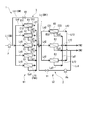
本発明の第一実施形態について、図面を参照して説明する。図1に示すように、本実施形態に係る水処理装置1は、被処理水SWが流通する取水ラインL1と、被処理水SWを取水ラインL1の上流から下流に圧送するポンプPと、複数の逆浸透膜装置(一次エレメントE1,二次エレメントE2)を有する一次ユニットU1、及び二次ユニットU2と、これら一次ユニットU1と二次ユニットU2とを互いに接続する接続ラインLcと、を備えている。さらに、この水処理装置1は、二次濃縮水CW2の一部を、一次ユニットU1と二次ユニットU2との間(接続ラインLc上)に還流させる還流部2を有している。
本発明の第一実施形態について、図面を参照して説明する。図1に示すように、本実施形態に係る水処理装置1は、被処理水SWが流通する取水ラインL1と、被処理水SWを取水ラインL1の上流から下流に圧送するポンプPと、複数の逆浸透膜装置(一次エレメントE1,二次エレメントE2)を有する一次ユニットU1、及び二次ユニットU2と、これら一次ユニットU1と二次ユニットU2とを互いに接続する接続ラインLcと、を備えている。さらに、この水処理装置1は、二次濃縮水CW2の一部を、一次ユニットU1と二次ユニットU2との間(接続ラインLc上)に還流させる還流部2を有している。
取水ラインL1は、外部から供給される被処理水SWを水処理装置1に導くための流路である。この取水ラインL1の上流側には、例えば前処理装置(不図示)が設けられている。この前処理装置では、海水中に含まれる生物が装置に付着することを抑制するための酸化剤や、微粒子、コロイド等を凝集させるための凝集剤の添加、及びpHの調整等が行われる。より具体的には、酸化剤としては次亜塩素酸などが好適に用いられる。さらに、凝集剤としては塩化第二鉄などの無機凝集剤や、PACなどの高分子凝集剤が用いられる。これら凝集剤によって凝集された懸濁物は、砂ろ過器によって取り除かれる。
このように、前処理を施された被処理水SWは、取水ラインL1上に設けられたポンプPによって、該取水ラインL1中を上流側から下流側に向かって圧送される。
一次ユニットU1、及び二次ユニットU2は、上記取水ラインL1によって導かれた被処理水SWを逆浸透によって分離・濃縮するための装置である。一次ユニットU1は、互いに並列に配置された複数の一次エレメントE1と、これら複数の一次エレメントE1に対して取水ラインL1中の被処理水SWを分配する一次分配ラインLd1と、一次エレメントE1から排出された一次濃縮水CW1、及び淡水(一次淡水FW1)がそれぞれ流通する一次集水ラインLg1、及び一次淡水ラインLf1と、を有している。
一次エレメントE1は、中空糸膜やスパイラル膜などの逆浸透膜(RO膜:Reverse Osmosis Membrane)を内部に備える逆浸透膜装置である。それぞれの一次エレメントE1は、ベッセルと呼ばれる外装部材と、このベッセル内部に配置された逆浸透膜と、を主に備えている。さらに、ベッセルには、上記分配ラインに接続される一次流入口E11と、一次集水ラインLg1、及び一次淡水ラインLf1にそれぞれ接続される一次集水口E12、及び一次淡水集水口E13と、が設けられている。
一次ユニットU1は、上記一次エレメントE1が互いに並列に配置されることで構成されている。一例として本実施形態では、5つの一次エレメントE1が並列に配置されている。より具体的には、取水ラインL1の下流側端部と、それぞれの一次エレメントE1の一次流入口E11とが、上記の分配ラインによって互いに接続されている。さらに、一次集水ラインLg1は、それぞれの一次エレメントE1の一次集水口E12と、接続ラインLc(後述)の上流側端部とを互いに接続している。一次淡水ラインLf1は、各一次エレメントE1中で分離された淡水を外部に排出・回収するための流路である。一次淡水ラインLf1の下流側には、回収された淡水を貯留するためのタンクや、さらなるろ過等を施すための設備が接続される(いずれも不図示)。以上のように構成されることで、5つの一次エレメントE1は互いに並列をなしている。
なお、本実施形態では5つの二次エレメントE2が設けられた例についてのみ説明するが、二次エレメントE2の個数は5つに限定されず、後述する二次エレメントE2の個数よりも多い限りにおいては4個以下であってもよいし、6個以上であってもよい。
なお、本実施形態では5つの二次エレメントE2が設けられた例についてのみ説明するが、二次エレメントE2の個数は5つに限定されず、後述する二次エレメントE2の個数よりも多い限りにおいては4個以下であってもよいし、6個以上であってもよい。
二次ユニットU2は、上記一次ユニットU1と同様の構成により、一次ユニットU1にて生成された一次濃縮水CW1をさらに分離・濃縮するための装置である。より詳細には、二次ユニットU2は、互いに並列に配置された複数の二次エレメントE2と、これら複数の二次エレメントE2に対して、一次ユニットU1にて生成された一次濃縮水CW1を分配する二次分配ラインLd2と、二次エレメントE2から排出された二次濃縮水CW2、及び淡水(二次淡水FW2)がそれぞれ流通する二次集水ラインLg2、及び二次淡水ラインLf2と、を有している。
二次エレメントE2は上記の一次エレメントE1と同等の構成と性能を有する逆浸透膜装置であるが、以下の説明ではこれらを区別する。二次エレメントE2のベッセルには、二次分配ラインLd2に接続される二次流入口E21と、二次集水ラインLg2、及び二次淡水ラインLf2にそれぞれ接続される二次集水口E22、及び二次淡水集水口E23と、が設けられている。
本実施形態では、3つの二次エレメントE2が互いに並列に配置されることで、二次ユニットU2を形成している。なお、二次ユニットU2における二次エレメントE2の個数は、上記一次ユニットU1における一次エレメントE1の個数よりも少なく設定される。本実施形態では、二次ユニットU2には3つの二次エレメントE2が設けられた例について説明するが、二次エレメントE2の個数は、上記一次エレメントE1よりも少ない限りにおいては2個であってもよいし、4個以上であってもよい。
接続ラインLcは、上記一次ユニットU1の下流側と、二次ユニットU2とを接続している。より詳細には、接続ラインLcは、一次ユニットU1におけるそれぞれの一次集水ラインLg1の下流側端部と、二次ユニットU2におけるそれぞれの二次分配ラインLd2の上流側端部とを互いに接続している。これにより、一次ユニットU1で生成された一次濃縮水CW1は、一次集水ラインLg1、接続ラインLc、及び二次分配ラインLd2の順に流通することで、二次ユニットU2の各二次エレメントE2に分配される。二次エレメントE2では、この一次濃縮水CW1がさらに分離・濃縮されることで、淡水(二次淡水FW2)と、この二次淡水FW2を除く残余の成分としての二次濃縮水CW2とが生成される。淡水は二次淡水ラインLf2を通じて回収される。二次濃縮水CW2は二次集水ラインLg2を通じて回収された後、不図示の外部設備による後処理等を経て外部に排出される。
さらに、本実施形態における水処理装置1では、二次濃縮水CW2の一部を一次ユニットU1と二次ユニットU2との間の流路に還流させる還流部2が設けられている。より具体的には、還流部2は、上記の二次集水ラインLg2から分岐して、上記の接続ラインLc上に接続される還流ラインLc1と、この還流ラインLc1上に設けられた還流ポンプPcと、還流ラインLc1の流通状態を切り替える還流弁V1と、を有している。
換言すれば、還流ラインLc1は、二次ユニットU2の下流側と上流側とを互いに接続している。ここで、二次ユニットU2の上流側では、濃縮水(一次濃縮水CW1)の圧力は、下流側に比して高くなっている。そこで、本実施形態に係る還流部2では、還流ポンプPcによって、還流ラインLc1に沿って下流側から上流側に向かって圧力を付加している。これにより、還流ラインLc1中の二次濃縮水CW2の一部は、二次ユニットU2の下流側(二次集水ラインLg2上)から上流側(接続ラインLc上)に向かって流通する。
還流弁V1は、具体的には、流量を調整することが可能な弁装置である。すなわち、還流弁V1の開度を調整することによって、還流ラインLc1中を流通する二次濃縮水CW2の量を調整することができる。
還流弁V1は、具体的には、流量を調整することが可能な弁装置である。すなわち、還流弁V1の開度を調整することによって、還流ラインLc1中を流通する二次濃縮水CW2の量を調整することができる。
次に、上述のように構成された水処理装置1の動作について説明する。
通常の運転状態では、上記の還流部2における還流弁V1は閉止されている。この状態でポンプPを駆動することで、被処理水SWが取水ラインL1を経て一次ユニットU1に導かれる。ポンプPによって加圧された被処理水SWは、各一次エレメントE1の逆浸透膜に対して高圧の状態で通水される。
通常の運転状態では、上記の還流部2における還流弁V1は閉止されている。この状態でポンプPを駆動することで、被処理水SWが取水ラインL1を経て一次ユニットU1に導かれる。ポンプPによって加圧された被処理水SWは、各一次エレメントE1の逆浸透膜に対して高圧の状態で通水される。
一次ユニットU1では、各一次エレメントE1中で被処理水SWに対する逆浸透が行われる。これにより、一次エレメントE1中では、被処理水SW中の塩分等が濃縮された一次濃縮水CW1と、この一次濃縮水CW1を除く残余の成分(淡水)である一次淡水FW1とが生成される。より詳細には、被処理水SWのうち、淡水成分が逆浸透膜を透過して下流側に達することで一次淡水FW1となる。一次淡水FW1が下流側に透過することで、逆浸透膜の上流側には、被処理水SWに含まれる塩類が濃縮される。これにより、逆浸透膜の上流側では一次濃縮水CW1が生成される。なお、逆浸透膜の下流側では、一次淡水FW1の圧力は上記の被処理水SWの圧力よりも小さくなっている。
一次淡水FW1は、上記の一次淡水ラインLf1を経て外部に回収される。一次濃縮水CW1は、一次集水ラインLg1中に集められた後、接続ラインLcを経て下流側の二次ユニットU2に流入する。二次ユニットU2では、接続ラインLcを経て流入した一次濃縮水CW1が、二次分配ラインLd2によって各二次エレメントE2にそれぞれ分配される。
二次エレメントE2中では、上記一次エレメントE1と同様に、一次濃縮水CW1からの淡水の分離と塩類の濃縮とが行われる。すなわち、一次濃縮水CW1中の淡水成分である二次淡水FW2と、この二次淡水FW2を除く残余の成分である二次濃縮水CW2とが生成される。
二次淡水FW2は、二次淡水FW2集水ラインによって外部に回収される。二次濃縮水CW2は、二次集水ラインLg2中に集められた後、外部の環境中に排出される。以上の動作が連続的に行われることにより、被処理水SW(海水)が淡水化される。
ところで、上記のような水処理装置1では、被処理水SWから回収される淡水の体積比率(淡水回収率)に対して、予め目標値が定められている。例えば海水を淡水化する場合、淡水回収率は、25~40%程度に設定される。しかしながら、装置の連続的な運用に伴って、逆浸透膜の性能が低下した場合には、淡水回収率は相対的に低下して、上記の目標値を下回る可能性がある。この場合、ポンプPの出力を上げることで、逆浸透膜に対する被処理水SWの供給圧力が高められる。被処理水SWの圧力が上がることにより、逆浸透膜において分離される淡水の量が増加し、淡水回収率が上昇に転じる。
その一方で、上記のように淡水回収率が上昇するに伴って、被処理水SWから分離される二次濃縮水CW2の量は減少する。ここで、逆浸透膜を用いた装置では、排出される濃縮水の量(流量)に下限値が設定されている。濃縮水の量がこの下限値を下回ると、膜モジュール内で濃度分極による膜面濃度の増加によりスケール析出等の不具合が生じ、十分な分離、濃縮が行えない可能性がある。
そこで、本実施形態に係る水処理装置1では、上記の還流部2によって二次濃縮水CW2の一部を二次ユニットU2の上流側(より具体的には、一次ユニットU1と二次ユニットU2との間の接続ラインLc上)に還流させている。これにより、二次ユニットU2における二次エレメントE2から排出される二次濃縮水CW2の量を相対的に増加させることができる。したがって、それぞれの二次エレメントE2から排出される二次濃縮水CW2の量を、上記下限値よりも大きくすることができる。
さらに、上記のような二次濃縮水CW2の還流は、還流ポンプPcの駆動、及び還流弁V1の開放のみによって容易に行うことができる。特に、この還流弁V1のような弁装置は、水処理装置1の通水中(運転中)に開閉することができる。すなわち、本実施形態に係る水処理装置1では、運転を停止させることなく、二次濃縮水CW2の一部を上流側に還流させることができる。これにより、水処理装置1の稼働率を下げることなく淡水回収率を向上させることができる。
加えて、上記のような水処理装置1では、淡水回収率を上げることで一次濃縮水CW1の量が減少した場合であっても、二次ユニットU2における全ての二次エレメントE2に通水させることができる。言い換えると、一次濃縮水CW1の量が減少した場合に、一部の二次エレメントE2を系統から切り離して処理不能とするなどの措置を取る必要がない。一般的に、処理不能となった逆浸透膜装置(二次エレメントE2)には、逆浸透膜を保護するために、保存液の充填を行う必要がある。しかしながら、上記構成によれば、全ての二次エレメントE2に対して濃縮水が通水されることから、保存液の充填等を行うための装置や工程を省略することができる。これにより、装置の施工コスト、及びメンテナンスコストを低減することができる。
[第二実施形態]
次に、本発明の第二実施形態について、図2を参照して説明する。なお、上述の第一実施形態と同様に構成については同一の符号を付し、詳細な説明を省略する。
図2に示すように、本実施形態に係る水処理装置1では、上述の還流部2に加えて、バイパス部3が設けられている。より詳細には、バイパス部3は、取水ラインL1上におけるポンプPと一次ユニットU1との間、及び、一次ユニットU1と二次ユニットU2との間を接続するバイパスラインLb1と、このバイパスラインLb1上に設けられたバイパス弁V2と、を備えている。
次に、本発明の第二実施形態について、図2を参照して説明する。なお、上述の第一実施形態と同様に構成については同一の符号を付し、詳細な説明を省略する。
図2に示すように、本実施形態に係る水処理装置1では、上述の還流部2に加えて、バイパス部3が設けられている。より詳細には、バイパス部3は、取水ラインL1上におけるポンプPと一次ユニットU1との間、及び、一次ユニットU1と二次ユニットU2との間を接続するバイパスラインLb1と、このバイパスラインLb1上に設けられたバイパス弁V2と、を備えている。
このようなバイパスラインLb1によって、取水ラインL1中を流通する被処理水SWの一部の成分が取り出されて、一次ユニットU1を経ずに、二次ユニットU2の上流側に導かれる。換言すれば、取水ラインL1から取り出された被処理水SWの一部の成分は、一次濃縮水CW1として二次ユニットU2に供給(還元)される。
上記のような構成によれば、二次ユニットU2における二次エレメントE2に導かれる一次濃縮水CW1の量を相対的に増加させることができる。これにより、それぞれの二次エレメントE2から排出される二次濃縮水CW2の量を、二次エレメントE2ごとに定められた濃縮水の量の下限値よりも大きくすることができる。
さらに、上記のような被処理水SWの取り出し、及びバイパスの各操作は、バイパス弁V2の開放のみによって容易に行うことができる。特に、このバイパス弁V2のような弁装置は、水処理装置1の通水中(運転中)に開閉することができる。したがって、本実施形態に係る水処理装置1では、運転を停止させることなく、被処理水SWの一部を二次ユニットU2に向けてバイパスさせることができる。これにより、水処理装置1の稼働率を下げることなく淡水回収率を向上させることができる。
以上、本発明の各実施形態について図面を参照して説明した。しかしながら、上記の各実施形態は一例に過ぎず、本発明の要旨を逸脱しない限りにおいて種々の変更を加えることが可能である。
例えば、上記の各実施形態における還流部2、バイパス部3を動作させるに当たっては、作業者の手によって行われてもよいし、図3に示す制御部によって行われてもよい。制御部4を用いる場合、上述の取水ラインL1上、及び接続ラインLc上に、計測部5を設けることで各ライン中の水(被処理水SW、一次濃縮水CW1、二次濃縮水CW2、一次淡水FW1、二次淡水FW2)の特性値が計測される。これら特性値に基づいて、制御部4は還流部2(還流弁V1)、バイパス部3(バイパス弁V2の開閉)を制御する。
より具体的には、計測部5としては、水の電気伝導度を計測することが可能な装置や、温度計などが適宜用いられる。
制御部4は、上記計測部5による計測によって得られた値に基づいて特性値を算出する演算部41と、演算部41によって算出された特性値に基づいて還流部2、及びバイパス部3の動作要否を判定する判定部42と、判定部42の判定に基づいて還流弁V1、バイパス弁V2の開度を電気信号として指示する信号生成部43と、を有している。
上記のような構成を採る場合、計測部5は、水の電気伝導度、温度、LSI(ランゲリア飽和指数:Langeliar Saturation Index)等の特性値を連続的に計測する。制御部4における判定部42は、これら特性値と、予め定められた基準値又は基準範囲との比較を行う。当該基準値又は基準範囲を満たす場合には、判定部42は淡水回収率を上げることができると判定して、上記還流弁V1、バイパス弁V2を開放する。
なお、LSIを指標として用いる際における、「当該基準値又は基準範囲を満たす場合」とは、LSIが当該基準値よりも小さい場合(例えば、0より小さい場合)が対応する。
なお、淡水回収率の増加可否の判定は、通常はLSIによりエレメントのスケール析出有無を確認して行うが、電気伝導度、温度に基づいて同様の判定をしてもよい。
一般的にLSIの値は、測定対象となる水の電気伝導度、及び温度の各値に依存する。さらに、電気伝導度は水中の溶存塩濃度(すなわち、電解質としてイオン状態で溶存した塩の濃度)によって決定される。また、水の温度が1℃上昇するに従って、LSIの値はおおむね1.5×10⁻²増加する。
したがって、計測部5によって電気伝導度、及び温度を計測した後、制御部4における演算部41が、これら特性値に基づく演算を行うことで、LSI換算値を算出する構成とすることも可能である。この場合であっても、制御部4の判定部42は、このLSI換算値に基づいて、淡水回収率の増加可否を判定する。
このような構成によれば、被処理水SWの水質に応じて、自律的に淡水回収率を最大化することが可能となる。特に、季節変動などによる水質の変化に対して水処理装置1の性能を柔軟に対応させることができる。
なお、還流部2とバイパス部3をともに備える場合、これら装置に対して予め優先順位を定めることが望ましい。例えば、淡水回収率を上げる必要がある場合、まず還流部2による二次濃縮水CW2の還流を優先的に行う構成が考えられる。さらに、二次濃縮水CW2の還流により、二次ユニットU2の入口における塩濃度が増加し、一次ユニットU1から排出される淡水(透過水)の量が相対的に増加することにより、透過水FLUXが許容値を超えてしまう場合は、これに加えてバイパス部3(バイパスラインLb1)を開通することによって、被処理水SWを二次ユニットU2に導入する構成とすることが望ましい。
上述した水処理装置1、及び水処理装置1の運転方法によれば、淡水回収率と稼働率とを向上させることができる。
1…水処理装置 2…還流部 3…バイパス部 4…制御部 41…演算部 42…判定部 43…信号生成部 5…計測部 CW1…一次濃縮水 CW2…二次濃縮水 E1…一次エレメント E11…一次流入口 E12…一次集水口 E13…一次淡水集水口 E2…二次エレメント E21…二次流入口 E22…二次集水口 E23…二次淡水集水口 FW1…一次淡水 FW2…二次淡水 L1…取水ライン Lb1…バイパスライン Lc…接続ライン Lc1…還流ライン Ld1…一次分配ライン Ld2…二次分配ライン Lf1…一次淡水ライン Lf2…二次淡水ライン Lg1…一次集水ライン Lg2…二次集水ライン P…ポンプ Pc…還流ポンプ SW…被処理水 U1…一次ユニット U2…二次ユニット V1…還流弁 V2…バイパス弁
Claims (5)
- 互いに並列に配置されて、上流側から供給される被処理水を一次濃縮水と淡水に分離する処理を行う逆浸透膜装置としての複数の一次エレメントを有する一次ユニットと、
前記被処理水を前記一次ユニットの上流側から圧送することで、該被処理水を前記一次ユニットに供給するポンプと、
前記一次エレメントよりも少ない個数が設けられるとともに、互いに並列に配置されて、前記一次濃縮水を二次濃縮水と淡水とに分離する処理を行う逆浸透膜装置としての二次エレメントを有する二次ユニットと、
前記二次濃縮水の一部を前記一次ユニットと前記二次ユニットとの間に還流させる還流部と、
を備える水処理装置。 - 前記還流部は、
前記二次ユニットの下流側、及び該二次ユニットの上流側を接続することで、前記二次濃縮水が流通する還流ラインと、
前記還流ライン上に設けられて、該還流ラインを流通する前記二次濃縮水を前記二次ユニットの上流側に向けて圧送する還流ポンプと、
を備える請求項1に記載の水処理装置。 - 前記被処理水の一部を、前記ポンプと前記一次ユニットとの間から、前記一次ユニットと前記二次ユニットとの間にバイパスさせるバイパスラインを備える請求項1又は2に記載の水処理装置。
- 前記被処理水、前記一次濃縮水、前記二次濃縮水、前記淡水の少なくとも1つにおける特性値を計測する計測部と、
前記特性値から得られるランゲリア飽和指数と、予め定められた基準値との比較に基づいて、前記還流部による前記二次濃縮水の還流を制御する制御部と、
を備える請求項1から3のいずれか一項に記載の水処理装置。 - 前記特性値は、前記被処理水、前記一次濃縮水、前記二次濃縮水、前記淡水の少なくとも1つにおける温度、又は電気伝導度であり、
前記制御部は、前記温度、及び電気伝導度に基づいて前記ランゲリア飽和指数を算出する演算部を備える請求項4に記載の水処理装置。
Priority Applications (2)
| Application Number | Priority Date | Filing Date | Title |
|---|---|---|---|
| PCT/JP2015/058436 WO2016151669A1 (ja) | 2015-03-20 | 2015-03-20 | 水処理装置 |
| US15/558,721 US20180071683A1 (en) | 2015-03-20 | 2015-03-20 | Water treatment device |
Applications Claiming Priority (1)
| Application Number | Priority Date | Filing Date | Title |
|---|---|---|---|
| PCT/JP2015/058436 WO2016151669A1 (ja) | 2015-03-20 | 2015-03-20 | 水処理装置 |
Publications (1)
| Publication Number | Publication Date |
|---|---|
| WO2016151669A1 true WO2016151669A1 (ja) | 2016-09-29 |
Family
ID=56977094
Family Applications (1)
| Application Number | Title | Priority Date | Filing Date |
|---|---|---|---|
| PCT/JP2015/058436 Ceased WO2016151669A1 (ja) | 2015-03-20 | 2015-03-20 | 水処理装置 |
Country Status (2)
| Country | Link |
|---|---|
| US (1) | US20180071683A1 (ja) |
| WO (1) | WO2016151669A1 (ja) |
Cited By (1)
| Publication number | Priority date | Publication date | Assignee | Title |
|---|---|---|---|---|
| US20190224624A1 (en) * | 2017-02-15 | 2019-07-25 | Hitachi, Ltd. | Reverse osmosis treatment apparatus and reverse osmosis treatment method |
Families Citing this family (2)
| Publication number | Priority date | Publication date | Assignee | Title |
|---|---|---|---|---|
| US10245556B2 (en) * | 2012-04-15 | 2019-04-02 | Ben Gurion University Of The Negev Research And Development Authority | Method and apparatus for effecting high recovery desalination with pressure driven membranes |
| CN110713230B (zh) * | 2019-10-22 | 2020-10-09 | 珠海格力电器股份有限公司 | 净水机回收率控制方法、装置、系统及净水机 |
Citations (6)
| Publication number | Priority date | Publication date | Assignee | Title |
|---|---|---|---|---|
| JP2011136283A (ja) * | 2009-12-28 | 2011-07-14 | Uerushii:Kk | 逆浸透膜ろ過装置及び逆浸透膜ろ過方法 |
| WO2012023469A1 (ja) * | 2010-08-17 | 2012-02-23 | 東レ株式会社 | 淡水製造装置およびその運転方法 |
| JP2012192374A (ja) * | 2011-03-17 | 2012-10-11 | Miura Co Ltd | 水処理装置 |
| JP2012206073A (ja) * | 2011-03-30 | 2012-10-25 | Kurita Water Ind Ltd | 脱イオン水製造システム |
| JP2013022544A (ja) * | 2011-07-25 | 2013-02-04 | Kubota Corp | 膜処理装置およびその運転方法 |
| JP2014061506A (ja) * | 2012-09-24 | 2014-04-10 | Hitachi Ltd | 液体処理設備 |
-
2015
- 2015-03-20 US US15/558,721 patent/US20180071683A1/en not_active Abandoned
- 2015-03-20 WO PCT/JP2015/058436 patent/WO2016151669A1/ja not_active Ceased
Patent Citations (6)
| Publication number | Priority date | Publication date | Assignee | Title |
|---|---|---|---|---|
| JP2011136283A (ja) * | 2009-12-28 | 2011-07-14 | Uerushii:Kk | 逆浸透膜ろ過装置及び逆浸透膜ろ過方法 |
| WO2012023469A1 (ja) * | 2010-08-17 | 2012-02-23 | 東レ株式会社 | 淡水製造装置およびその運転方法 |
| JP2012192374A (ja) * | 2011-03-17 | 2012-10-11 | Miura Co Ltd | 水処理装置 |
| JP2012206073A (ja) * | 2011-03-30 | 2012-10-25 | Kurita Water Ind Ltd | 脱イオン水製造システム |
| JP2013022544A (ja) * | 2011-07-25 | 2013-02-04 | Kubota Corp | 膜処理装置およびその運転方法 |
| JP2014061506A (ja) * | 2012-09-24 | 2014-04-10 | Hitachi Ltd | 液体処理設備 |
Cited By (1)
| Publication number | Priority date | Publication date | Assignee | Title |
|---|---|---|---|---|
| US20190224624A1 (en) * | 2017-02-15 | 2019-07-25 | Hitachi, Ltd. | Reverse osmosis treatment apparatus and reverse osmosis treatment method |
Also Published As
| Publication number | Publication date |
|---|---|
| US20180071683A1 (en) | 2018-03-15 |
Similar Documents
| Publication | Publication Date | Title |
|---|---|---|
| JP5361928B2 (ja) | 海水淡水化装置およびその制御方法 | |
| JP5933926B2 (ja) | 海水淡水化システム及び海水淡水化方法 | |
| US20180280888A1 (en) | Reverse osmosis treatment apparatus and reverse osmosis treatment method | |
| JP5330901B2 (ja) | 塩及び淡水の併産装置及び方法 | |
| JP5941629B2 (ja) | 水浄化システム及び水浄化方法 | |
| CN106413860B (zh) | 渗透分离系统和方法 | |
| CN101801857B (zh) | 水处理方法、水处理装置、净化水的回收方法及净化水回收装置 | |
| US20190224624A1 (en) | Reverse osmosis treatment apparatus and reverse osmosis treatment method | |
| JP2012223723A (ja) | 海水淡水化システムの制御装置及びその制御方法 | |
| KR101389450B1 (ko) | 담수화 장치 및 이를 이용한 담수화 방법 | |
| WO2012111402A1 (ja) | 水処理システム及びその凝集剤注入方法 | |
| JP2012206073A (ja) | 脱イオン水製造システム | |
| KR102528075B1 (ko) | 액 처리 장치, 순수 제조 시스템 및 액 처리 방법 | |
| JP5075597B2 (ja) | 浄化水回収装置及び浄化水の回収方法 | |
| JP5067299B2 (ja) | 膜ろ過システム、及び膜ろ過システムの運転方法 | |
| Kurth et al. | Design considerations for implementing ceramics in new and existing polymeric UF systems | |
| KR101550702B1 (ko) | 높은 회수율로 정수 생산을 위한 막여과 정수 처리 시스템 및 방법 | |
| KR101402345B1 (ko) | 고효율 역삼투 해수담수화 시스템 | |
| KR101730878B1 (ko) | Ro-fo-ro 공정을 이용한 농축폐수 처리장치 및 처리방법 | |
| US20180071683A1 (en) | Water treatment device | |
| CN102548907B (zh) | 用于提高普通反渗透系统的性能的闭环淡化改进 | |
| KR101752553B1 (ko) | 이중 순환형 정삼투-역삼투 복합 수처리 시스템 및 이의 제어방법 | |
| WO2016151673A1 (ja) | 水処理装置、及び水処理装置の運転方法 | |
| JP2013052349A (ja) | 造水方法 | |
| US11485660B1 (en) | System and method for desalination |
Legal Events
| Date | Code | Title | Description |
|---|---|---|---|
| 121 | Ep: the epo has been informed by wipo that ep was designated in this application |
Ref document number: 15886226 Country of ref document: EP Kind code of ref document: A1 |
|
| WWE | Wipo information: entry into national phase |
Ref document number: 15558721 Country of ref document: US |
|
| NENP | Non-entry into the national phase |
Ref country code: DE |
|
| 122 | Ep: pct application non-entry in european phase |
Ref document number: 15886226 Country of ref document: EP Kind code of ref document: A1 |
|
| NENP | Non-entry into the national phase |
Ref country code: JP |