WO2016151642A1 - Unité intérieure pour climatiseur - Google Patents
Unité intérieure pour climatiseur Download PDFInfo
- Publication number
- WO2016151642A1 WO2016151642A1 PCT/JP2015/001751 JP2015001751W WO2016151642A1 WO 2016151642 A1 WO2016151642 A1 WO 2016151642A1 JP 2015001751 W JP2015001751 W JP 2015001751W WO 2016151642 A1 WO2016151642 A1 WO 2016151642A1
- Authority
- WO
- WIPO (PCT)
- Prior art keywords
- refrigerant
- indoor unit
- air conditioner
- air
- detection sensor
- Prior art date
Links
Images


Classifications
-
- F—MECHANICAL ENGINEERING; LIGHTING; HEATING; WEAPONS; BLASTING
- F24—HEATING; RANGES; VENTILATING
- F24F—AIR-CONDITIONING; AIR-HUMIDIFICATION; VENTILATION; USE OF AIR CURRENTS FOR SCREENING
- F24F1/00—Room units for air-conditioning, e.g. separate or self-contained units or units receiving primary air from a central station
- F24F1/0007—Indoor units, e.g. fan coil units
- F24F1/0068—Indoor units, e.g. fan coil units characterised by the arrangement of refrigerant piping outside the heat exchanger within the unit casing
-
- F—MECHANICAL ENGINEERING; LIGHTING; HEATING; WEAPONS; BLASTING
- F25—REFRIGERATION OR COOLING; COMBINED HEATING AND REFRIGERATION SYSTEMS; HEAT PUMP SYSTEMS; MANUFACTURE OR STORAGE OF ICE; LIQUEFACTION SOLIDIFICATION OF GASES
- F25B—REFRIGERATION MACHINES, PLANTS OR SYSTEMS; COMBINED HEATING AND REFRIGERATION SYSTEMS; HEAT PUMP SYSTEMS
- F25B49/00—Arrangement or mounting of control or safety devices
- F25B49/02—Arrangement or mounting of control or safety devices for compression type machines, plants or systems
-
- F—MECHANICAL ENGINEERING; LIGHTING; HEATING; WEAPONS; BLASTING
- F24—HEATING; RANGES; VENTILATING
- F24F—AIR-CONDITIONING; AIR-HUMIDIFICATION; VENTILATION; USE OF AIR CURRENTS FOR SCREENING
- F24F1/00—Room units for air-conditioning, e.g. separate or self-contained units or units receiving primary air from a central station
- F24F1/0003—Room units for air-conditioning, e.g. separate or self-contained units or units receiving primary air from a central station characterised by a split arrangement, wherein parts of the air-conditioning system, e.g. evaporator and condenser, are in separately located units
-
- F—MECHANICAL ENGINEERING; LIGHTING; HEATING; WEAPONS; BLASTING
- F24—HEATING; RANGES; VENTILATING
- F24F—AIR-CONDITIONING; AIR-HUMIDIFICATION; VENTILATION; USE OF AIR CURRENTS FOR SCREENING
- F24F11/00—Control or safety arrangements
- F24F11/30—Control or safety arrangements for purposes related to the operation of the system, e.g. for safety or monitoring
- F24F11/32—Responding to malfunctions or emergencies
- F24F11/36—Responding to malfunctions or emergencies to leakage of heat-exchange fluid
-
- F—MECHANICAL ENGINEERING; LIGHTING; HEATING; WEAPONS; BLASTING
- F24—HEATING; RANGES; VENTILATING
- F24F—AIR-CONDITIONING; AIR-HUMIDIFICATION; VENTILATION; USE OF AIR CURRENTS FOR SCREENING
- F24F13/00—Details common to, or for air-conditioning, air-humidification, ventilation or use of air currents for screening
- F24F13/20—Casings or covers
-
- F—MECHANICAL ENGINEERING; LIGHTING; HEATING; WEAPONS; BLASTING
- F24—HEATING; RANGES; VENTILATING
- F24F—AIR-CONDITIONING; AIR-HUMIDIFICATION; VENTILATION; USE OF AIR CURRENTS FOR SCREENING
- F24F13/00—Details common to, or for air-conditioning, air-humidification, ventilation or use of air currents for screening
- F24F13/22—Means for preventing condensation or evacuating condensate
- F24F13/222—Means for preventing condensation or evacuating condensate for evacuating condensate
- F24F2013/227—Condensate pipe for drainage of condensate from the evaporator
-
- F—MECHANICAL ENGINEERING; LIGHTING; HEATING; WEAPONS; BLASTING
- F24—HEATING; RANGES; VENTILATING
- F24F—AIR-CONDITIONING; AIR-HUMIDIFICATION; VENTILATION; USE OF AIR CURRENTS FOR SCREENING
- F24F2110/00—Control inputs relating to air properties
-
- F—MECHANICAL ENGINEERING; LIGHTING; HEATING; WEAPONS; BLASTING
- F25—REFRIGERATION OR COOLING; COMBINED HEATING AND REFRIGERATION SYSTEMS; HEAT PUMP SYSTEMS; MANUFACTURE OR STORAGE OF ICE; LIQUEFACTION SOLIDIFICATION OF GASES
- F25B—REFRIGERATION MACHINES, PLANTS OR SYSTEMS; COMBINED HEATING AND REFRIGERATION SYSTEMS; HEAT PUMP SYSTEMS
- F25B2500/00—Problems to be solved
- F25B2500/22—Preventing, detecting or repairing leaks of refrigeration fluids
- F25B2500/222—Detecting refrigerant leaks
Definitions
- This invention relates to an indoor unit of an air conditioner.
- HFC refrigerant R410A has been mainly used as the refrigerant filled in the refrigerant circuit in the air conditioner. Unlike the conventional HCFC refrigerant such as R22, this R410A has the property that the ozone depletion coefficient ODP is zero and does not destroy the ozone layer, but has a high global warming potential GWP. Therefore, as part of the prevention of global warming, there is a movement to change from an HFC refrigerant having a high GWP such as R410A to an HFC refrigerant having a low GWP.
- HFO refrigerants these are referred to as HFO refrigerants, and have a carbon double bond in the composition such as R32 (CH2F2; difluoromethane) and R125 (CHF2-CF3; pentafluoroethane) constituting R410A. Shall be distinguished from no HFC refrigerant.
- Such a low GWP HFO refrigerant may be used as a single refrigerant, but is likely to be used as a mixed refrigerant with other HFC refrigerants typified by R32.
- these HFO refrigerants or mixed refrigerants of HFO refrigerants and HFC refrigerants are not as flammable as HC refrigerants such as R290 (C3H8; propane), they are slightly inflammable unlike R410A, which is nonflammable. Have. Therefore, it is necessary to pay attention to the leakage of the refrigerant.
- the refrigerant having flammability including the slight flammability to the strong flammability is referred to as a flammable refrigerant.
- R32 Since R32 exhibits a slight flammability as a single refrigerant, that is, a flammable refrigerant, a mixed refrigerant of the HFO refrigerant and R32 also becomes a flammable refrigerant.
- R410A in which R125 is mixed with R125 is nonflammable due to the characteristics of R125.
- the refrigerant may leak due to poor connection or corrosion of the refrigerant piping for circulating the refrigerant between the indoor unit and the outdoor unit.
- the leaked refrigerant can be stored in the indoor unit at a concentration higher than the flammable concentration. If the leaked refrigerant having a high concentration flows out of the indoor unit, if there is an ignition source near the indoor unit, the leaked refrigerant may be ignited. For example, the surface of the indoor unit may be damaged by ignition. Therefore, some measures are necessary to avoid ignition of the leaked refrigerant.
- Patent Document 1 discloses a configuration in which a refrigerant leaked from a heat exchanger disposed in a heat exchange chamber is caused to flow through a drain pan into a piping chamber, and the refrigerant leakage is detected by a sensor provided in the piping chamber. ing. When the leaked refrigerant is detected, the blower is operated to blow the leaked refrigerant out of the indoor unit. With this configuration, the refrigerant is prevented from staying in the indoor unit at a concentration higher than the flammable concentration.
- Patent Documents 2 and 3 a hole is made in a wall of a house, a ventilation path extending from the outdoor unit is inserted into the wall, and a leaked refrigerant in the indoor unit is caused to flow out of the ventilation path.
- Patent Document 1 In the configuration of Patent Document 1, when a refrigerant leak occurs in the machine room, the leaked refrigerant is stored in the machine room until at least the height of the drain pan is reached, and the refrigerant exists in a high concentration state in the machine room. There was a problem that.
- Patent Documents 2 and 3 in order to allow the refrigerant to flow out of the indoor unit, it is necessary to provide an air passage extending from the indoor unit, and the structure is complicated. In addition, it is necessary to make a hole in the wall of the house, and further, there is a problem that this ventilation path has to be inserted into the hole in the wall and installation is not easy.
- the present invention has been made in order to solve the above-described problems, and is to provide an indoor unit of an air conditioner that can be easily installed and can quickly leak a leaked refrigerant out of the indoor unit. .
- An indoor unit of an air conditioner includes a casing provided with an air inlet and an outlet for indoor air, a connection pipe having a pipe connection portion connected to a refrigerant pipe of the outdoor unit via a relay pipe, A heat exchanger for exchanging heat between the refrigerant flowing from the outdoor unit through the connection pipe and the air sucked into the casing, and sucking air into the casing from the suction port, and exchanging heat by the heat exchanger
- a fan that generates an air flow that blows out the air that has been blown out of the housing from the outlet, a drain pan that is provided below the heat exchanger, and stores drain water generated by heat exchange between the refrigerant and the air,
- An air conditioner indoor unit wherein the suction port is provided at a position lower than the height position of the drain pan, and a partition plate for partitioning a space below the height position of the drain pan in the housing is provided.
- the pipe connection part is disposed in one of the partitioned spaces, the heat exchanger and the fan are disposed in
- the indoor unit of the air conditioner of the present invention can be easily installed, and the leaked refrigerant can be quickly discharged out of the indoor unit.
- FIG. 1 It is sectional drawing of the indoor unit of the air conditioner in Embodiment 1 of this invention. It is the perspective view which removed the front casing, the front panel, and the filter of the indoor unit of FIG. It is the expansion perspective view which expanded the partition plate periphery part of FIG. It is a schematic diagram which shows the structure of the indoor unit of FIG. It is the front view which expanded the partition plate periphery part of FIG. It is a schematic diagram which shows the structure of the indoor unit of the air conditioner in Embodiment 2 of this invention. It is a schematic diagram which shows the structure of the indoor unit of the air conditioner in Embodiment 3 of this invention. It is a front view which shows the modification of the indoor unit of FIG. It is a schematic diagram which shows the structure of the indoor unit of the air conditioner in Embodiment 4 of this invention.
- FIG. 1 is a cross-sectional view of an indoor unit 1 of an air conditioner according to the present embodiment.
- FIG. 2 is a perspective view in which the front casing 2b, the front panel 3, and the filter 7 of the indoor unit 1 are removed and viewed obliquely.
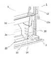
- FIG. 3 is an enlarged perspective view in which the peripheral portion of the partition plate 13 in FIG. 2 is enlarged.
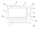
- FIG. 4 is a schematic diagram illustrating the structure of the indoor unit 1.
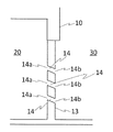
- FIG. 5 is an enlarged front view of the peripheral portion of the partition plate 13 of FIG.
- the indoor unit 1 can be placed on the floor surface of the room that is subject to air conditioning.
- the housing 2 includes a rear casing 2a and a front casing 2b.
- the front surface of the front casing 2 b is configured as a front panel 3.
- a room air inlet 4 is formed below the front panel 3.
- a heat exchanger 5 and a fan 6 are accommodated in the housing 2.
- the heat exchanger 5 is a fin-and-tube heat exchanger including a plurality of fins 5a arranged in parallel and tubes 5b penetrating the fins 5a, and is arranged in a substantially V shape in a side view.
- the fan 6 is a so-called cross flow fan that blows air with a cylindrical runner.
- the room air exchanged with the refrigerant flowing through the tube 5b of the heat exchanger 5 is sucked up by the operation of the fan 6 and is supplied from the outlet 8 of the outlet unit 9 provided above the front panel 3 to the housing 2. It is blown out.
- the blowout unit 9 includes a wind direction flap 9a and a stabilizer 9b that control the wind direction of the blown air.
- the wind direction flap 9a is rotatable, and FIG. 1 shows a state in which the wind direction flap 9a is opened.
- the drain pan 10 is a groove-shaped container having an upper surface opened and extending in the left-right direction when viewed from the front. The drain water is drained outdoors through a drain hose (not shown) connected to the drain pan 10.
- a side of the heat exchanger 5 is connected to a control unit 11 including an electric circuit for controlling the operation of the indoor unit 1 and a refrigerant pipe (not shown) of the outdoor unit via a relay pipe (not shown).
- a connecting pipe 12 is provided.
- One end of the connection pipe 12 is connected to the tube 5b of the heat exchanger 5, and the other end is provided with a connection part (hereinafter referred to as a pipe connection part) 12a connected to the refrigerant pipe of the outdoor unit via a relay pipe.
- the connection method in the pipe connection part 12a is, for example, flare connection.
- a space in which the suction port 4, the heat exchanger 5, the fan 6, and the air outlet 8 are provided is referred to as an air passage chamber 20.
- a space located on the side of the air passage chamber 20 and provided with the pipe connection portion 12a is referred to as a pipe chamber 30.
- the suction port 4 is located on the lower front side of the air passage chamber 20, and the air outlet 8 is located on the upper side.
- the room air sucked from the suction port 4 by the fan 6 passes through the heat exchanger 5 and the fan 6 and is blown out from the outlet 8.
- the flow path of the indoor air from the inlet 4 to the outlet 8 is referred to as the air path in the indoor unit 1.
- the relay pipe can be considered as a part of the refrigerant pipe of the outdoor unit, and these two pipes can be collectively used as the refrigerant pipe of the outdoor unit.
- a partition plate 13 is disposed at the boundary between the air channel chamber 20 and the piping chamber 30.
- the partition plate 13 is provided between the bottom surface of the housing 2 and the drain pan 10, and partitions the space in the housing 2 below the height position of the drain pan 10.
- the partition plate 13 is formed with a communication passage 14 that allows the air passage chamber 20 and the piping chamber 30 to communicate with each other. That is, the communication path 14 is provided below the height position of the drain pan 10.
- the partition plate 13 is located on the back side of the front panel 3. Three rectangular communication paths 14 are formed side by side on the partition plate 13.
- the communication path 14 includes a so-called opening.
- the communication path 14 formed in the partition plate 13 is inclined toward the outlet 5 side. That is, the inlet / outlet port 14a on the air passage chamber 20 side of the communication passage 14 is located closer to the outlet 5 side than the inlet / outlet port 14b on the piping chamber 30 side. According to such a configuration, the leakage refrigerant in the piping chamber 30 is easily drawn into the air passage chamber 20 by the air current flowing in the air passage chamber 20 from the inlet 4 toward the outlet 8, and rides on the air flow. It becomes easy to flow to the outlet 8.
- the total area of the entrance / exit surface of the communication path 14 is 1 ⁇ 2 or less of the total area of the partition plate 13.
- the total area of the entrance / exit surface of the communication passage 14 is the total area of the partition plate 13. It is preferable that it is 1/20 or more of an area. That is, the total area of the entrance / exit surface of the communication path 14 is preferably 1/20 or more and 1/2 or less of the total area of the partition plate 13.
- the two communication passages 14 are preferably formed at positions below the partition plate 13, that is, near the bottom surface of the housing 2.
- at least one communication path 14 is formed at a position lower than a height position corresponding to 1 ⁇ 2 of the distance between the bottom surface of the drain pan 10 and the bottom surface of the housing 2.
- the partition plate 13 is provided with a plurality of communication paths 14.
- the communication path 14 is formed at a distance between the bottom surface of the drain pan 10 and the bottom surface of the housing 2. It is preferable to form also in a position higher than the height position corresponding to 1/2. Three or more communication paths 14 may be provided at substantially equal intervals.
- the amount of leakage refrigerant drawn is further increased. Can do a lot.
- the indoor unit 1 includes a receiving unit (not shown) that receives a cooling or heating operation command from the remote controller, and a control unit 11 that controls the cooling operation and the heating operation according to the content of the operation command received by the receiving unit. And have.
- a refrigeration cycle is formed by the heat exchanger 5 of the indoor unit 1, the compressor, the heat exchanger of the outdoor unit, and an expansion valve (not shown). The refrigerant and the room air flowing in from (not shown) exchange heat in the heat exchanger 5 and perform cooling or heating action.
- HFO refrigerants are combustible refrigerants that burn when there is an ignition source when the concentration with respect to air is equal to or higher than a predetermined value.
- the combustible refrigerant of this embodiment includes a slightly flammable refrigerant.
- the operation is as follows. Since the specific gravity of the refrigerant such as HFO-1234yf is larger than the specific gravity of air, the refrigerant leaking from the pipe connection portion 12 a flows toward the bottom of the pipe chamber 30. When the indoor unit 1 has stopped cooling and heating operations, the leaked refrigerant is gradually stored from the bottom of the piping chamber 20. When the storage height of the leakage refrigerant reaches the height at which the communication passage 14 is formed, the leakage refrigerant flows from the piping chamber 30 into the air passage chamber 20 via the communication passage 14. The refrigerant that has flowed into the air passage chamber 20 flows out of the indoor unit 1 through the suction port 4.
- the leaked refrigerant is not stored in the piping chamber 30, but diffuses from the suction port 4 to the indoor floor surface by its own weight.
- the specific gravity of the leaked refrigerant is heavier than the specific gravity of the air, and the leaked refrigerant on the floor surface is sequentially pushed in the direction away from the indoor unit 1 by the subsequent leaked refrigerant and spreads widely over the floor surface. Therefore, even when the indoor unit 1 is a so-called floor-standing type, the concentration of the leaked refrigerant can be made lower than the flammable concentration.
- the refrigerant leaking from the pipe connection portion 12a and flowing into the air channel chamber 20 from the piping chamber 30 through the communication path 14 passes through the air channel chamber 20.
- the air is blown out of the indoor unit 1 from the air outlet 8 on the air flow of the air drawn from the air inlet 4 toward the air outlet 8.
- the communication passage 14 is formed to be inclined as shown in FIG. 5, the leaked refrigerant is easily drawn into the air passage chamber 20 by the airflow of the suction air from the suction port 4 toward the blowout port 8. .
- the leaked refrigerant is not stored in the piping chamber 30, but has an effect of reliably diffusing from the outlet 8 into the room.
- the indoor unit 1 of the air conditioner of the present embodiment is installed at the boundary between the air channel chamber 20 and the piping chamber 30 and partitions the space below the height position of the drain pan 10 in the housing 2.
- a partition plate 14 is provided.
- a communication path 14 that connects the air passage chamber 20 and the piping chamber 30 is formed.
- the leakage refrigerant flows into the air channel chamber 20 from the piping chamber 30 through the communication path 14, and passes through the suction port 4 or the outlet 8. It can flow out of the machine 1.
- the leakage refrigerant in the piping chamber 30 flows into the air passage chamber 20 through the communication passage 14 and from the suction port 4 provided below the air passage chamber 20. It flows out to the indoor floor and diffuses.
- the leaked refrigerant in the piping chamber 30 flows into the air passage chamber 20 through the communication path 14 and rides on the airflow of the intake air from the suction port 4 toward the blowout port 8.
- the leaked refrigerant can be diffused outside the indoor unit 1 so as to be less than the flammable concentration.
- the communication path 14 is provided at a position lower than the height position of the drain pan 10, even when refrigerant leakage occurs in the piping chamber 30, the refrigerant leaks to the outside of the outdoor unit 1 with little storage in the piping chamber 30. Can be quickly and reliably diffused.
- a sensor for refrigerant detection is unnecessary, and diffusion of leaked refrigerant can be realized at low cost.
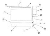
- FIG. FIG. 6 is a schematic diagram showing the structure of the air conditioner indoor unit 1 according to Embodiment 2 of the present invention.
- a refrigerant detection sensor 15 that detects refrigerant leakage is provided in the housing 2.
- the refrigerant detection sensor 15 is provided in the piping chamber 30.
- the control unit 11 operates the fan 6 when the refrigerant leakage is detected by the refrigerant detection sensor 15 when the indoor unit 1 stops the cooling and heating operation and is in the operation standby state.
- the refrigerant that has leaked into the air passage chamber 20 from the piping chamber 30 through the communication passage 14 is generated by the fan 6. It is diffused out of the indoor unit 1 through the air outlet 8 by riding on the airflow. Thereby, even when the indoor unit 1 is in operation standby, the leaked refrigerant can be reliably diffused widely outside the indoor unit 1.
- the leaked refrigerant flows out from the suction port 4 and from the air passage chamber 20 through the communication passage 14. It can flow into the piping chamber 30.
- the refrigerant detection sensor 15 detects refrigerant leakage and the control unit 11 operates the fan 6, whereby the leakage refrigerant is diffused from the blowout port 8 to the outside of the indoor unit 1.
- the leaked refrigerant can be widely diffused from the blowout port 8 to the outside of the indoor unit 1.
- the refrigerant detection sensor 15 is provided in the piping chamber 30, but it can also be provided in the air passage chamber 20. Even in this case, the same effect is obtained by the same operation. Further, a temperature detection sensor (not shown) can be separately provided in the housing 2. When there is a refrigerant leak, the heat in the casing 2 is taken away by the vaporization of the leaked refrigerant, and the temperature in the casing 2 decreases. In the outdoor unit 1, the control unit 11 operates the fan 6 when the refrigerant is detected by the refrigerant detection sensor 15 and the temperature obtained by the temperature detection sensor falls below a set temperature. You can also. According to such a configuration, it is possible to improve the detection accuracy of the refrigerant leak, and when the refrigerant leaks, the leaked refrigerant can be widely diffused outside the outdoor unit 1.
- the refrigerant detection sensor 15 is not provided, and the control unit 11 can operate the fan 6 when the temperature obtained by the temperature detection sensor (not shown) falls below a set temperature. . According to this configuration, the leaked refrigerant can be diffused widely outside the outdoor unit 1 only by the temperature detection sensor.
- FIG. 7 is a schematic diagram showing the structure of the air conditioner indoor unit 1 according to Embodiment 3 of the present invention.
- a refrigerant detection sensor 15 that detects refrigerant leakage is provided in the housing 2.
- the indoor unit 1 is also provided with an opening / closing mechanism 16 that can open and close the communication path 14 of the partition plate 13.
- the opening / closing mechanism 16 can be configured as an opening / closing plate such as a damper.
- the opening / closing mechanism 16 is a damper 16 and is provided in the vicinity of the partition plate 13 in the air passage chamber 20 so as to be rotatable.
- the control unit 11 rotates and fixes the damper 16 at a position where the communication path 14 is closed.
- the control unit 11 connects the damper 16 to the communication path.
- the communication path 14 is opened by turning in a direction away from the communication path 14.
- the communication path 14 when the refrigerant detection sensor 15 does not detect refrigerant leakage, the communication path 14 is closed to block the passage of gas between the pipe chamber 20 and the air passage chamber 30, and the refrigerant distribution When leakage is detected, the communication path 14 is opened, and the refrigerant leaked into the piping chamber 20 is caused to flow into the air passage chamber 30 and diffused from the outlet 8 by the operation of the fan 6.
- the communication path 14 is closed by the opening / closing mechanism 16, so that no gas flows between the air passage chamber 20 and the piping chamber 30. Therefore, it is possible to prevent the outside air that has entered the piping chamber 30 from the gap of the insertion hole of the refrigerant pipe provided on the wall surface of the installation room of the indoor unit 1 from flowing into the air passage chamber 20 via the communication path 14. Thereby, the air conditioning quality at the time of cooling and heating operation of the indoor unit 1 can be improved. Further, when the refrigerant leaks, the communication passage 14 is opened, so that the leakage refrigerant flows from the piping chamber 30 into the air passage chamber 20 via the communication passage 14.
- the leaked refrigerant flows out from the suction port 4 due to its own weight during standby, and diffuses out of the outdoor unit 2 from the outlet 8 by riding on the airflow generated by the operation of the fan 6 during heating or cooling operation.
- the indoor unit 1 of the present embodiment there is an effect that the leaked refrigerant can be diffused widely outside the indoor unit 1 without reducing the quality of air conditioning.
- FIG. 8 is a schematic diagram showing a modification of the indoor unit 1 of FIG.
- the damper 16 is rotatably installed in the vicinity of the partition plate 13 in the piping chamber 30.
- Other configurations are the same as those in FIG. Also with the configuration of FIG. 8, the same effect can be obtained by the same operation as in the case of FIG.
- the refrigerant detection sensor 15 causes refrigerant leakage as in the second embodiment. If detected, the fan 6 can be operated. According to this operation, the same effects as those of the second embodiment can be obtained.
- control unit 11 can operate the fan 6 when the refrigerant detection sensor 15 detects refrigerant leakage, and can perform control to issue an abnormality alarm.
- an alarm lamp (not shown) is provided on the front panel 3, and an alarm can be issued to the user by blinking the lamp.
- a speaker (not shown) is provided in the indoor unit 1, and thereby a warning sound can be generated to alert the user.
- the communication path 14 is opened, the leaked refrigerant is quickly diffused, and a warning appealing to the sight or hearing is issued to the user, so that the post-processing of the refrigerant leak can be performed quickly.
- FIG. 9 is a schematic diagram showing the structure of the air conditioner indoor unit 1 according to Embodiment 4 of the present invention.
- the indoor unit 1 is provided with an opening / closing mechanism 16 that can freely open and close the communication path 14 of the partition plate 13.
- the opening / closing mechanism 16 may be configured as an opening / closing plate such as a damper.
- the opening / closing mechanism 16 is a damper 16 and is provided in the vicinity of the partition plate 13 in the air passage chamber 20 so as to be rotatable.
- the control unit 11 periodically opens and closes the entrances 14a and 14b of the communication path 14 by rotating the damper 16. The period is, for example, 5 seconds to 3 minutes. That is, in the present embodiment, the gas in the piping chamber 20 is periodically introduced into the air passage chamber 30 and diffused from the blowout port 8 by the operation of the fan 6.
- the number, shape, and size of the communication path 14 in the first to fourth embodiments are merely examples, and the present invention is not limited to this. It is sufficient that at least one communication path 14 is formed in the partition plate 13.
- the shape of the communication path 14 when the partition plate 13 is viewed in plan is not limited to a rectangle, but may be any other shape such as other polygons or circles. Further, the communication path 14 may be formed perpendicular to the surface of the partition plate 13 without being inclined with respect to the surface of the partition plate 13. That is, the inlet / outlet port 14a on the air passage chamber 20 side and the inlet / outlet port 14b on the piping chamber 30 side of the communication passage 14 may be at the same height position.
- the air channel chamber 20 and the piping chamber 30 do not necessarily have to be partitioned on the side higher than the height position where the drain pan 10 is provided.
- the air channel chamber 20 and the piping chamber 30 may be partitioned by a structure such as a side plate (not shown) provided on the side surface of the heat exchanger 5, for example.
- a structure such as a side plate (not shown) provided on the side surface of the heat exchanger 5, for example.
- some gaps may exist in the structure.
- the specific gravity of the leaked refrigerant is larger than the specific gravity of air. The effect that it can be made to flow out can be produced. Even in this case, the same effects as those of the above embodiment can be obtained.
- Embodiments 1 to 4 are examples in which the partition plate 13 is provided as an independent member as shown in FIGS. 2 and 3, but is not limited thereto.
- the partition plate 13 may be formed integrally with the front panel 3. That is, the partition plate 13 may be configured as a part of the front panel 3.
- the partition plate 13 may be configured as a part of the housing 2 or the drain pan 10. Even in these cases, the same effects as those of the first to fourth embodiments can be obtained.
- Embodiments 2 and 3 above are examples in which the refrigerant detection sensor 15 is provided in the piping chamber 30, but the present invention is not limited to this.
- the refrigerant detection sensor 15 can also be provided in the air passage chamber 20. Even in this case, refrigerant leakage in the air passage chamber 20 can be detected, and refrigerant that has leaked in the piping chamber 30 and has flowed into the air passage chamber 20 via the communication passage 14 can also be detected.
- the refrigerant detection sensor 15 is preferably provided at a position lower than the height position of the bottom of the drain pan 10.
- the refrigerant detection sensor 15 when there is a refrigerant leak from the heat exchanger 5, it is possible to quickly detect the refrigerant leaking from the drain pan 10 and having a greater specific gravity than air. Further, when the refrigerant detection sensor 15 is installed in the air passage chamber 20, it is further preferable that the refrigerant detection sensor 15 is provided at a position lower than the height position of the communication path 14. If it is this position, when there is a refrigerant leak in the piping chamber 30, it is possible to quickly detect the leakage of the refrigerant having a greater specific gravity than air that has flowed into the air passage chamber 20 via the communication path 14.
Landscapes
- Engineering & Computer Science (AREA)
- Mechanical Engineering (AREA)
- General Engineering & Computer Science (AREA)
- Chemical & Material Sciences (AREA)
- Combustion & Propulsion (AREA)
- Physics & Mathematics (AREA)
- Thermal Sciences (AREA)
- Air Conditioning Control Device (AREA)
- Devices For Blowing Cold Air, Devices For Blowing Warm Air, And Means For Preventing Water Condensation In Air Conditioning Units (AREA)
- Air Filters, Heat-Exchange Apparatuses, And Housings Of Air-Conditioning Units (AREA)
- Other Air-Conditioning Systems (AREA)
Abstract
Priority Applications (6)
| Application Number | Priority Date | Filing Date | Title |
|---|---|---|---|
| JP2017507119A JP6332552B2 (ja) | 2015-03-26 | 2015-03-26 | 空気調和機の室内機 |
| PCT/JP2015/001751 WO2016151642A1 (fr) | 2015-03-26 | 2015-03-26 | Unité intérieure pour climatiseur |
| US15/537,013 US10760839B2 (en) | 2015-03-26 | 2015-03-26 | Indoor unit of air-conditioning apparatus having leaked refrigerant ventilation |
| EP15886199.7A EP3264000B1 (fr) | 2015-03-26 | 2015-03-26 | Unité intérieure pour climatiseur |
| NZ733257A NZ733257A (en) | 2015-03-26 | 2015-03-26 | Indoor unit of air-conditioning apparatus |
| AU2015388399A AU2015388399B2 (en) | 2015-03-26 | 2015-03-26 | Indoor unit of air-conditioning apparatus |
Applications Claiming Priority (1)
| Application Number | Priority Date | Filing Date | Title |
|---|---|---|---|
| PCT/JP2015/001751 WO2016151642A1 (fr) | 2015-03-26 | 2015-03-26 | Unité intérieure pour climatiseur |
Publications (1)
| Publication Number | Publication Date |
|---|---|
| WO2016151642A1 true WO2016151642A1 (fr) | 2016-09-29 |
Family
ID=56977039
Family Applications (1)
| Application Number | Title | Priority Date | Filing Date |
|---|---|---|---|
| PCT/JP2015/001751 WO2016151642A1 (fr) | 2015-03-26 | 2015-03-26 | Unité intérieure pour climatiseur |
Country Status (6)
| Country | Link |
|---|---|
| US (1) | US10760839B2 (fr) |
| EP (1) | EP3264000B1 (fr) |
| JP (1) | JP6332552B2 (fr) |
| AU (1) | AU2015388399B2 (fr) |
| NZ (1) | NZ733257A (fr) |
| WO (1) | WO2016151642A1 (fr) |
Cited By (7)
| Publication number | Priority date | Publication date | Assignee | Title |
|---|---|---|---|---|
| CN106895561A (zh) * | 2017-02-28 | 2017-06-27 | 广东美的制冷设备有限公司 | 一种检测空调器冷媒泄漏的方法、空调器的控制装置和空调器 |
| EP3578894A4 (fr) * | 2017-02-01 | 2020-01-15 | Mitsubishi Electric Corporation | Climatiseur |
| WO2020031234A1 (fr) * | 2018-08-06 | 2020-02-13 | ダイキン工業株式会社 | Système de climatisation |
| WO2020031233A1 (fr) * | 2018-08-06 | 2020-02-13 | ダイキン工業株式会社 | Système de climatisation |
| WO2020144769A1 (fr) * | 2019-01-09 | 2020-07-16 | 三菱電機株式会社 | Appareil de climatisation |
| CN112393413A (zh) * | 2020-11-30 | 2021-02-23 | 珠海格力电器股份有限公司 | 接水盘组件及其控制方法、空调 |
| JPWO2022107220A1 (fr) * | 2020-11-17 | 2022-05-27 |
Families Citing this family (9)
| Publication number | Priority date | Publication date | Assignee | Title |
|---|---|---|---|---|
| JP6477767B2 (ja) * | 2017-03-31 | 2019-03-06 | ダイキン工業株式会社 | 冷凍装置 |
| JP6614389B1 (ja) * | 2019-07-12 | 2019-12-04 | ダイキン工業株式会社 | 冷凍装置の室内機 |
| CN110486827B (zh) * | 2019-08-22 | 2023-05-16 | 青岛海尔空调器有限总公司 | 柜式空调室内机 |
| CN110486823B (zh) * | 2019-08-22 | 2023-04-18 | 青岛海尔空调器有限总公司 | 柜式空调室内机 |
| CN110486825B (zh) * | 2019-08-22 | 2023-06-09 | 青岛海尔空调器有限总公司 | 柜式空调室内机 |
| CN110486824B (zh) * | 2019-08-22 | 2023-03-21 | 青岛海尔空调器有限总公司 | 柜式空调室内机 |
| CN110486807B (zh) * | 2019-08-22 | 2023-06-23 | 青岛海尔空调器有限总公司 | 柜式空调室内机 |
| CN110486826B (zh) * | 2019-08-22 | 2023-06-09 | 青岛海尔空调器有限总公司 | 柜式空调室内机 |
| CN112628994A (zh) * | 2021-01-11 | 2021-04-09 | 青岛海尔空调器有限总公司 | 滑动面板及立式空调 |
Citations (5)
| Publication number | Priority date | Publication date | Assignee | Title |
|---|---|---|---|---|
| JPH11304226A (ja) * | 1998-04-23 | 1999-11-05 | Matsushita Electric Ind Co Ltd | 空気調和機 |
| JP2003074894A (ja) * | 2001-08-28 | 2003-03-12 | Toshiba Kyaria Kk | 空気調和機 |
| JP2005282981A (ja) * | 2004-03-30 | 2005-10-13 | Matsushita Electric Ind Co Ltd | 冷却装置 |
| JP2013044515A (ja) * | 2011-08-26 | 2013-03-04 | Noritz Corp | ヒートポンプ給湯装置 |
| JP2015055448A (ja) * | 2013-09-13 | 2015-03-23 | 三菱電機株式会社 | 冷凍サイクル装置 |
Family Cites Families (15)
| Publication number | Priority date | Publication date | Assignee | Title |
|---|---|---|---|---|
| JP3291407B2 (ja) * | 1995-01-31 | 2002-06-10 | 三洋電機株式会社 | 冷房装置 |
| JPH09324928A (ja) | 1996-06-05 | 1997-12-16 | Daikin Ind Ltd | 可燃性冷媒を用いた空気調和機 |
| JPH10115478A (ja) * | 1996-10-09 | 1998-05-06 | Sanyo Electric Co Ltd | 空気調和機 |
| JPH11325517A (ja) * | 1998-03-17 | 1999-11-26 | Hitoyoshi Aizawa | ル―ムエアコンの冷媒配管装置 |
| JP2001165468A (ja) | 1999-12-10 | 2001-06-22 | Matsushita Electric Ind Co Ltd | 冷房または冷暖房装置 |
| US6425253B1 (en) * | 2000-06-02 | 2002-07-30 | Daimlerchrysler Corporation | Method for detecting low-charge condition in air conditioning system and device incorporating same |
| JP3744330B2 (ja) | 2000-09-26 | 2006-02-08 | ダイキン工業株式会社 | 空気調和機の室内機 |
| JP4639451B2 (ja) * | 2000-09-26 | 2011-02-23 | ダイキン工業株式会社 | 空気調和機 |
| US6637232B1 (en) * | 2002-07-24 | 2003-10-28 | .Pef Industries, Inc. | Unit ventilator |
| US20090107157A1 (en) * | 2007-10-25 | 2009-04-30 | Serge Dube | Refrigerant leak-detection systems |
| DK2110614T3 (en) * | 2008-04-16 | 2014-12-15 | Truma Gerätetechnik Gmbh & Co Kg | Air conditioner with safety device to avoid refrigerant penetration into the indoor area |
| JP2012013348A (ja) * | 2010-07-02 | 2012-01-19 | Panasonic Corp | 空気調和機 |
| WO2013038599A1 (fr) * | 2011-09-14 | 2013-03-21 | パナソニック株式会社 | Climatiseur |
| US9879871B2 (en) * | 2014-06-13 | 2018-01-30 | Lennox Industries Inc. | HVAC systems and methods with refrigerant leak detection |
| US11079149B2 (en) * | 2015-06-09 | 2021-08-03 | Carrier Corporation | System and method of diluting a leaked refrigerant in an HVAC/R system |
-
2015
- 2015-03-26 US US15/537,013 patent/US10760839B2/en active Active
- 2015-03-26 AU AU2015388399A patent/AU2015388399B2/en active Active
- 2015-03-26 JP JP2017507119A patent/JP6332552B2/ja active Active
- 2015-03-26 WO PCT/JP2015/001751 patent/WO2016151642A1/fr active Application Filing
- 2015-03-26 NZ NZ733257A patent/NZ733257A/en unknown
- 2015-03-26 EP EP15886199.7A patent/EP3264000B1/fr active Active
Patent Citations (5)
| Publication number | Priority date | Publication date | Assignee | Title |
|---|---|---|---|---|
| JPH11304226A (ja) * | 1998-04-23 | 1999-11-05 | Matsushita Electric Ind Co Ltd | 空気調和機 |
| JP2003074894A (ja) * | 2001-08-28 | 2003-03-12 | Toshiba Kyaria Kk | 空気調和機 |
| JP2005282981A (ja) * | 2004-03-30 | 2005-10-13 | Matsushita Electric Ind Co Ltd | 冷却装置 |
| JP2013044515A (ja) * | 2011-08-26 | 2013-03-04 | Noritz Corp | ヒートポンプ給湯装置 |
| JP2015055448A (ja) * | 2013-09-13 | 2015-03-23 | 三菱電機株式会社 | 冷凍サイクル装置 |
Non-Patent Citations (1)
| Title |
|---|
| See also references of EP3264000A4 * |
Cited By (15)
| Publication number | Priority date | Publication date | Assignee | Title |
|---|---|---|---|---|
| US11067303B2 (en) | 2017-02-01 | 2021-07-20 | Mitsubishi Electric Corporation | Air-conditioning apparatus |
| EP3578894A4 (fr) * | 2017-02-01 | 2020-01-15 | Mitsubishi Electric Corporation | Climatiseur |
| AU2017396590B2 (en) * | 2017-02-01 | 2020-03-12 | Mitsubishi Electric Corporation | Air-conditioning apparatus |
| CN106895561B (zh) * | 2017-02-28 | 2019-07-30 | 广东美的制冷设备有限公司 | 一种检测空调器冷媒泄漏的方法、空调器的控制装置和空调器 |
| CN106895561A (zh) * | 2017-02-28 | 2017-06-27 | 广东美的制冷设备有限公司 | 一种检测空调器冷媒泄漏的方法、空调器的控制装置和空调器 |
| WO2020031234A1 (fr) * | 2018-08-06 | 2020-02-13 | ダイキン工業株式会社 | Système de climatisation |
| WO2020031233A1 (fr) * | 2018-08-06 | 2020-02-13 | ダイキン工業株式会社 | Système de climatisation |
| US11879650B2 (en) | 2018-08-06 | 2024-01-23 | Daikin Industries, Ltd. | Air conditioning system |
| WO2020144769A1 (fr) * | 2019-01-09 | 2020-07-16 | 三菱電機株式会社 | Appareil de climatisation |
| JPWO2020144769A1 (ja) * | 2019-01-09 | 2021-09-09 | 三菱電機株式会社 | 空気調和装置 |
| JP6991369B2 (ja) | 2019-01-09 | 2022-01-12 | 三菱電機株式会社 | 空気調和装置 |
| JPWO2022107220A1 (fr) * | 2020-11-17 | 2022-05-27 | ||
| WO2022107220A1 (fr) * | 2020-11-17 | 2022-05-27 | 三菱電機株式会社 | Dispositif de climatisation |
| JP7433474B2 (ja) | 2020-11-17 | 2024-02-19 | 三菱電機株式会社 | 空気調和装置 |
| CN112393413A (zh) * | 2020-11-30 | 2021-02-23 | 珠海格力电器股份有限公司 | 接水盘组件及其控制方法、空调 |
Also Published As
| Publication number | Publication date |
|---|---|
| AU2015388399A1 (en) | 2017-07-13 |
| US10760839B2 (en) | 2020-09-01 |
| JPWO2016151642A1 (ja) | 2017-06-29 |
| EP3264000B1 (fr) | 2019-08-14 |
| JP6332552B2 (ja) | 2018-05-30 |
| AU2015388399B2 (en) | 2018-07-26 |
| EP3264000A1 (fr) | 2018-01-03 |
| US20170343258A1 (en) | 2017-11-30 |
| EP3264000A4 (fr) | 2018-11-07 |
| NZ733257A (en) | 2019-06-28 |
Similar Documents
| Publication | Publication Date | Title |
|---|---|---|
| JP6332552B2 (ja) | 空気調和機の室内機 | |
| JP6355734B2 (ja) | 空気調和装置の室内機、及びその室内機を備えた空気調和装置 | |
| JP5818849B2 (ja) | 空気調和装置および冷媒漏洩検知方法 | |
| WO2016153021A1 (fr) | Unité intérieure de climatiseur | |
| JP3159200B2 (ja) | 空気調和装置 | |
| JP6785883B2 (ja) | 空気調和装置 | |
| WO2016047278A1 (fr) | Appareil de pompe à chaleur | |
| JP2002098393A (ja) | 空気調和機 | |
| MX2015003248A (es) | Dispositivo de ciclo de refrigeracion. | |
| JP6177158B2 (ja) | 空気調和機 | |
| JP2016029322A (ja) | 空気調和装置 | |
| WO2017168834A1 (fr) | Unité d'intérieur pour climatiseur | |
| JP6906168B2 (ja) | 室内ユニット | |
| JP6584649B2 (ja) | 空気調和機 | |
| JP2019138556A (ja) | 冷媒検知装置、及び空気調和機 | |
| JP6272149B2 (ja) | 空気調和装置 | |
| JP6653455B1 (ja) | 室内ユニット | |
| WO2016046965A1 (fr) | Dispositif à cycle de réfrigération | |
| US10254030B2 (en) | Refrigeration cycle device | |
| JP2021127987A (ja) | 室内ユニット |
Legal Events
| Date | Code | Title | Description |
|---|---|---|---|
| 121 | Ep: the epo has been informed by wipo that ep was designated in this application |
Ref document number: 15886199 Country of ref document: EP Kind code of ref document: A1 |
|
| ENP | Entry into the national phase |
Ref document number: 2017507119 Country of ref document: JP Kind code of ref document: A |
|
| WWE | Wipo information: entry into national phase |
Ref document number: 15537013 Country of ref document: US |
|
| REEP | Request for entry into the european phase |
Ref document number: 2015886199 Country of ref document: EP |
|
| ENP | Entry into the national phase |
Ref document number: 2015388399 Country of ref document: AU Date of ref document: 20150326 Kind code of ref document: A |
|
| NENP | Non-entry into the national phase |
Ref country code: DE |