WO2016148459A1 - 폐냉매제의 분해 및 부산물 고형화 방법 및 그 장치 - Google Patents
폐냉매제의 분해 및 부산물 고형화 방법 및 그 장치 Download PDFInfo
- Publication number
- WO2016148459A1 WO2016148459A1 PCT/KR2016/002508 KR2016002508W WO2016148459A1 WO 2016148459 A1 WO2016148459 A1 WO 2016148459A1 KR 2016002508 W KR2016002508 W KR 2016002508W WO 2016148459 A1 WO2016148459 A1 WO 2016148459A1
- Authority
- WO
- WIPO (PCT)
- Prior art keywords
- waste refrigerant
- decomposition
- plasma
- refrigerant gas
- waste
- Prior art date
- Legal status (The legal status is an assumption and is not a legal conclusion. Google has not performed a legal analysis and makes no representation as to the accuracy of the status listed.)
- Ceased
Links
Images







Classifications
-
- F—MECHANICAL ENGINEERING; LIGHTING; HEATING; WEAPONS; BLASTING
- F25—REFRIGERATION OR COOLING; COMBINED HEATING AND REFRIGERATION SYSTEMS; HEAT PUMP SYSTEMS; MANUFACTURE OR STORAGE OF ICE; LIQUEFACTION SOLIDIFICATION OF GASES
- F25B—REFRIGERATION MACHINES, PLANTS OR SYSTEMS; COMBINED HEATING AND REFRIGERATION SYSTEMS; HEAT PUMP SYSTEMS
- F25B43/00—Arrangements for separating or purifying gases or liquids; Arrangements for vaporising the residuum of liquid refrigerant, e.g. by heat
-
- H—ELECTRICITY
- H05—ELECTRIC TECHNIQUES NOT OTHERWISE PROVIDED FOR
- H05H—PLASMA TECHNIQUE; PRODUCTION OF ACCELERATED ELECTRICALLY-CHARGED PARTICLES OR OF NEUTRONS; PRODUCTION OR ACCELERATION OF NEUTRAL MOLECULAR OR ATOMIC BEAMS
- H05H1/00—Generating plasma; Handling plasma
- H05H1/24—Generating plasma
-
- B—PERFORMING OPERATIONS; TRANSPORTING
- B01—PHYSICAL OR CHEMICAL PROCESSES OR APPARATUS IN GENERAL
- B01D—SEPARATION
- B01D53/00—Separation of gases or vapours; Recovering vapours of volatile solvents from gases; Chemical or biological purification of waste gases, e.g. engine exhaust gases, smoke, fumes, flue gases, aerosols
- B01D53/32—Separation of gases or vapours; Recovering vapours of volatile solvents from gases; Chemical or biological purification of waste gases, e.g. engine exhaust gases, smoke, fumes, flue gases, aerosols by electrical effects other than those provided for in group B01D61/00
-
- Y—GENERAL TAGGING OF NEW TECHNOLOGICAL DEVELOPMENTS; GENERAL TAGGING OF CROSS-SECTIONAL TECHNOLOGIES SPANNING OVER SEVERAL SECTIONS OF THE IPC; TECHNICAL SUBJECTS COVERED BY FORMER USPC CROSS-REFERENCE ART COLLECTIONS [XRACs] AND DIGESTS
- Y02—TECHNOLOGIES OR APPLICATIONS FOR MITIGATION OR ADAPTATION AGAINST CLIMATE CHANGE
- Y02C—CAPTURE, STORAGE, SEQUESTRATION OR DISPOSAL OF GREENHOUSE GASES [GHG]
- Y02C20/00—Capture or disposal of greenhouse gases
- Y02C20/30—Capture or disposal of greenhouse gases of perfluorocarbons [PFC], hydrofluorocarbons [HFC] or sulfur hexafluoride [SF6]
Definitions
- the present invention relates to a method for decomposing and solidifying by-products of waste refrigerants, and more particularly, to a method for decomposing waste refrigerants and solidifying by-products that can solidify by-products generated after decomposition of waste refrigerants. And to the apparatus.
- the refrigerants used in refrigeration equipment such as refrigerators and automobiles include dichlorodifluoromethane (R-12), which may damage the ozone layer, or R-12 and 1,1-difluoroethane ( R-500 consisting of R-152a) or chlorodifluoromethane (HCFC-22), an alternative refrigerant that reduces the content of chlorine groups with high global warming effect but has a low risk of destroying the ozone layer.
- R-12 dichlorodifluoromethane
- R-500 1,1-difluoroethane
- HCFC-22 chlorodifluoromethane
- Refrigerants such as difluoromethane (HFC-32, R-32), trifluoromethane (HFC-23, R-23), pentafluoroethane (HFC-125, R-125), 1, 1, 1, 2-tetrafluoroethane (HFC-134a, R-134a), 1, 1, 1-trifluoroethane (HFC-143a, R-143a), but a fluorocarbon system containing no chlorine group and hydrogen Flammable hydrocarbons such as refrigerant (FC-based refrigerant), propane, butane and pentane, helium, ammonia and air.
- FC-based refrigerant propane, butane and pentane, helium, ammonia and air.
- Korean Patent Laid-Open No. 2011-0023253 discloses an apparatus and method for treating waste refrigerant by burning it together with solid waste.
- the existing waste refrigerant treatment method is to incinerate a small amount in a large waste incinerator or cement kiln, in addition to a large amount of combustion gas generated by the combustion of the waste refrigerant and waste, as well as harmful substances such as nitrogen dioxide, and to remove it
- a large waste incinerator or cement kiln in addition to a large amount of combustion gas generated by the combustion of the waste refrigerant and waste, as well as harmful substances such as nitrogen dioxide, and to remove it
- harmful substances such as nitrogen dioxide
- a method of treating waste refrigerant in a plasma reactor using a plasma torch such as argon plasma arc, microwave plasma, inductively coupled radiofrequency plasma, and nitrogen plasma arc has been used.
- waste refrigerant is decomposed using the conventional waste refrigerant treatment methods, since the waste refrigerant contains halogen group elements such as fluorine (F) and chlorine (Cl), by-products containing fluorine and chlorine are generated after decomposition of the waste refrigerant. Additional equipment must be provided for the removal of by-products such as fluorine and chlorine at the stage of decomposition of the waste refrigerant or at a later stage such that off-gases containing by-products such as fluorine and chlorine are not released into the atmosphere.
- halogen group elements such as fluorine (F) and chlorine (Cl)
- the present invention provides a method and apparatus for decomposing the waste refrigerant and solidifying the by-product which can solve the problem that it is difficult to process the by-product containing fluorine and chlorine generated after decomposition of the waste refrigerant, which is a disadvantage of the conventional waste refrigerant treatment method. to provide.
- the present invention also provides a method and apparatus for decomposing the waste refrigerant and solidifying the by-products, which can effectively decompose the waste refrigerant using plasma.
- decomposition and by-product solidification method of the waste refrigerant to produce a high value-added metal compound resources by solidifying the fluorine or chlorine contained in the waste refrigerant gas decomposed by the plasma by fluorine or chlorine metal compound and its Provide the device.
- the present invention is to decompose the waste refrigerant which is one or more compounds of chlorofluorocarbons (CFC), chlorofluorocarbons (HCFC), and hydrofluorocarbons (HFC) containing fluorine or chlorine by plasma or Decomposing the waste refrigerant by plasmalizing the gas containing the waste refrigerant; And a solidification step of contacting the decomposed waste refrigerant gas with a metal compound to generate a metal compound of fluorine or chlorine.
- CFC chlorofluorocarbons
- HCFC chlorofluorocarbons
- HFC hydrofluorocarbons
- solidification means NaF or CaCl 2 , CaF through chemical reaction with fluorine or chlorine valent metal compounds (eg, NaOH, Ca (OH) 2 or CaCO 3 ) from spent refrigerants. It means that it is formed of a metal compound of fluorine or chlorine such as 2 , which means that atoms from the decomposed gas can be synthesized into a new solid compound and easily recovered.
- fluorine or chlorine valent metal compounds eg, NaOH, Ca (OH) 2 or CaCO 3
- the solidifying step allows the decomposed waste refrigerant gas to be in contact with the metal compound at a temperature of 600 ° C. or less. At this time, the temperature may be controlled within a temperature of 600 °C or less according to the type of the metal compound.
- the reaction with the metal compound at a temperature of 400 ⁇ 200 °C.
- the present invention provides a decomposition and by-product solidification apparatus of the waste refrigerant of the present invention for implementing the decomposition and by-product solidification method of the waste refrigerant.
- the decomposition and by-product solidification apparatus of the waste refrigerant of the present invention is a plasma decomposition apparatus configured to decompose the waste refrigerant by the generated plasma or to decompose the waste refrigerant by plasmaizing the gas containing the waste refrigerant, wherein the waste refrigerant is fluorine or
- a plasma decomposition apparatus which is a compound of any one or more of chlorofluorocarbon (CFC), chlorofluorofluorocarbon (HCFC), and hydrofluorocarbon (HFC) including chlorine; And is disposed at a position where the waste refrigerant gas decomposed by the plasma decomposition device is discharged, and is configured so that the discharged decomposition waste refrigerant gas is introduced therein, and the metal compound is contained in or supplied from the outside to decompose the discharged metal compound.
- a solidifying device configured to generate a fluorine or chlorine metal compound in contact with the waste refrigerant gas.
- the metal compound is configured such that the temperature of the decomposition waste refrigerant gas discharged into the solidification device is 600 ° C. or less, preferably 400 ° C. to 200 ° C., in the solidification device.
- the metal compound is at least one metal atom selected from the group consisting of calcium (Ca), sodium (Na), manganese (Mn), iron (Fe), cobalt (Co), nickel (Ni) and copper (Cu) It may be a compound of.
- the metal compound used in the present invention means a compound containing the atom, such as Ca (OH) 2 , CaCO 3 and NaOH, and the present invention is not particularly limited to these examples.
- the plasma decomposition apparatus comprises: an external reactor having a cylindrical shape, the first side portion being perpendicular to the axial direction of the cylinder and a second side portion opposing the first side portion; A cylinder having a diameter smaller than that of the outer reactor, inserted into the outer reactor toward the second side portion, and a portion inserted into the outer reactor extends toward the first side portion with a length shorter than that of the outer reactor; Internal reactor; A plasma injection unit connected to the first side portion and positioned to inject plasma in an axial direction of the external reactor and spaced apart from an end of an inserted portion of the internal reactor; A gas injector connected to a circumferential surface of the outer reactor at a position proximate to the second side part, for injecting waste refrigerant gas into the outer reactor; And it may include a discharge portion located at the end of the second side portion of the inner reactor.
- the waste refrigerant gas may be further decompressed.
- the decomposed waste refrigerant gas may be contacted with a metal compound to generate a fluorine or chlorine metal compound.
- the waste refrigerant decomposition and by-product solidification apparatus of the present invention further comprises a heat exchanger connected between the solidification apparatus and the plasma decomposition apparatus,
- the heat exchanger is located at a position where the waste refrigerant gas decomposed by the plasma decomposition device is discharged, and configured to reduce the decomposition waste refrigerant gas discharged, and the solidification device passes through the heat exchanger to reduce the temperature of the decomposition waste.
- a refrigerant gas is introduced, and a metal compound is contained inside or supplied from the outside to react the metal compound with the introduced decomposition waste refrigerant gas to generate a metal compound of fluorine or chlorine.
- the decomposed waste refrigerant gas is reduced to a temperature of 600 ° C or lower, preferably 400 to 200 ° C.
- the method and apparatus for decomposing the waste refrigerant and solidifying the by-products according to the present invention effectively decompose the waste refrigerant using plasma, and replace fluorine or chlorine contained in the waste refrigerant gas decomposed by the plasma with a metal compound of fluorine or chlorine. Because it can be produced and solidified, it can produce resources of high value-added metal compounds, and the solidification process that generates fluorine or chlorine metal compounds removes harmful components of fluorine and chlorine contained in waste refrigerants. There is an advantage that the discharge of environmentally friendly gas after the refrigerant treatment can be made.
- 1 is a flow chart illustrating a process of the decomposition and by-product solidification method of the waste refrigerant of the present invention.
- Figure 2 is a block diagram conceptually showing the decomposition and by-product solidification apparatus of the waste refrigerant of the present invention.
- Figure 3a is a view showing an embodiment of a plasma decomposition device of the decomposition of the waste refrigerant and by-product solidification device of the present invention.
- 3B is a cross-sectional view of the connection structure of the gas injection unit of the plasma decomposition apparatus illustrated in FIG.
- Figure 4a shows the result of injecting chlorodifluoromethane (CHClF 2 ) in Experimental Example 1 at a flow rate of 1 lpm.
- Figure 4b shows the result of injecting chlorodifluoromethane (CHClF 2 ) in Experimental Example 1 at a flow rate of 3 lpm.
- Figure 4c shows the result of injecting chlorodifluoromethane (CHClF 2 ) in Experimental Example 1 at a flow rate of 5 lpm.
- 6A shows an example of the solidification apparatus.
- 6B shows another example of the solidification apparatus.
- FIG. 7 is a cross-sectional view illustrating a state in which the plasma decomposition apparatus illustrated in FIG. 3A and the solidification apparatus illustrated in FIG. 4A are connected.
- FIG. 8 shows the results of measurement using EDX analysis equipment to determine whether fluorine adheres to the metal compound by reacting the decomposition waste refrigerant gas with the metal compound in each region of the solidification apparatus shown in FIG. 7 through Experimental Example 3. The graph shown.
- FIG. 9 is a graph of respective regions showing the results of measurement using XRD analysis equipment to determine whether metal compounds combined with fluorine (F) are generated in each region of the solidification apparatus shown in FIG. 7 through Experimental Example 3.
- FIG. 9 is a graph of respective regions showing the results of measurement using XRD analysis equipment to determine whether metal compounds combined with fluorine (F) are generated in each region of the solidification apparatus shown in FIG. 7 through Experimental Example 3.
- FIG. 10A shows a photograph of the powder produced in the first region of the solidifying apparatus shown in FIG. 7 and a transmission electron microscope photograph of the powder through Experimental Example 3.
- FIG. 10A shows a photograph of the powder produced in the first region of the solidifying apparatus shown in FIG. 7 and a transmission electron microscope photograph of the powder through Experimental Example 3.
- FIG. 10B shows a photograph of the powder produced in the second region of the solidification apparatus shown in FIG. 7 and a transmission electron microscope photograph of the powder through Experimental Example 3.
- FIG. 10B shows a photograph of the powder produced in the second region of the solidification apparatus shown in FIG. 7 and a transmission electron microscope photograph of the powder through Experimental Example 3.
- FIG. 10C shows a photograph of the powder produced in the third region of the solidification apparatus shown in FIG. 7 and a transmission electron micrograph of the powder through Experimental Example 3.
- FIG. 10C shows a photograph of the powder produced in the third region of the solidification apparatus shown in FIG. 7 and a transmission electron micrograph of the powder through Experimental Example 3.
- FIG. 11A shows XRD data of calcium hydroxide (Ca (OH) 2 ) before decomposition of chlorodifluoromethane (CHClF 2 ) in Experimental Example 4.
- FIG. 11A shows XRD data of calcium hydroxide (Ca (OH) 2 ) before decomposition of chlorodifluoromethane (CHClF 2 ) in Experimental Example 4.
- FIG. 11B shows XRD data of a metal compound formed by combining fluorine (F) and calcium hydroxide (Ca (OH) 2 ) after decomposition of chlorodifluoromethane (CHClF 2 ) in Experimental Example 4.
- FIG. 11B shows XRD data of a metal compound formed by combining fluorine (F) and calcium hydroxide (Ca (OH) 2 ) after decomposition of chlorodifluoromethane (CHClF 2 ) in Experimental Example 4.
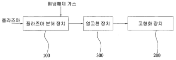
- FIG. 12 is a block diagram conceptually showing the configuration of another embodiment of the decomposition and by-product solidification apparatus of the waste refrigerant of the present invention.
- first and second may be used to describe various components, but the components should not be limited by the terms. The terms are used only for the purpose of distinguishing one component from another.
- the first component may be referred to as the second component, and similarly, the second component may also be referred to as the first component.
- 1 is a flow chart illustrating a process of the decomposition and by-product solidification method of the waste refrigerant of the present invention.
- the decomposition of the waste refrigerant and by-product solidification method of the present invention comprises the steps of decomposing the waste refrigerant by plasma or plasma containing the waste refrigerant to decompose the waste refrigerant (S110); And solidifying step S120 of contacting the decomposed waste refrigerant gas with a metal compound to generate a metal compound of fluorine or chlorine.
- the decomposed waste refrigerant gas is brought into contact with the metal compound at a temperature of 600 ° C. or less.
- the temperature may be controlled within a temperature of 600 °C or less according to the type of the metal compound.
- the reaction with the metal compound at a temperature of 400 ⁇ 200 °C.
- the decomposition and by-product solidification apparatus of the waste refrigerant of the present invention is used.
- Figure 2 is a block diagram conceptually showing the decomposition and by-product solidification apparatus of the waste refrigerant of the present invention.
- the decomposition and by-product solidification apparatus of the waste refrigerant of the present invention includes a plasma decomposition apparatus 100 and a solidification apparatus 200.
- the plasma decomposition apparatus 100 is configured to decompose the waste refrigerant by the generated plasma or to decompose the waste refrigerant by plasmalizing the gas containing the waste refrigerant.
- the plasma injected into the plasma decomposition apparatus 100 may be an electromagnetic plasma.
- a plasma torch generator may be used to inject the electromagnetic plasma.
- Korean Patent Publication No. 10-0394994 which is a previously registered patent of the inventor of the present application. This patent is incorporated herein by reference in its entirety.
- the waste refrigerant is a compound of any one or more of fluorocarbon (CFC), chlorofluorocarbon (HCFC), and hydrogen fluorocarbon (HFC) containing fluorine or chlorine.
- CFC fluorocarbon
- HCFC chlorofluorocarbon
- HFC hydrogen fluorocarbon
- the plasma decomposition apparatus 100 there is no particular limitation on the form of the plasma decomposition apparatus 100, and the hollow tube type, the plasma injection unit capable of injecting plasma, the gas injection unit capable of injecting waste refrigerant gas, and the waste refrigerant gas decomposed by plasma As long as it is a form which has a structure of the discharge part discharged, it is possible.
- Figure 3a is a view showing an embodiment of a plasma decomposition device of the decomposition of the waste refrigerant and by-product solidification device of the present invention.
- the plasma decomposition apparatus 100 may include an external reactor 110, an internal reactor 120, a plasma injection unit 130, a gas injection unit 140, and a discharge unit 150.
- the outer reactor 110 is a part forming the outer appearance of the reactor.
- the outer reactor 110 is cylindrical and includes a first side portion 111 perpendicular to the axial direction of the cylinder and a second side portion 112 opposite the first side portion 111.
- the first side portion 111 and the second side portion 112 may be in the form of a circular plate.
- the first side portion 111 and the second side portion 112 may have a circular shape corresponding to the diameter of the cylinder, or may have a circular shape larger than the diameter of the cylinder.
- the inner reactor 120 is cylindrical and the cylinder has a smaller diameter than the outer reactor 110. This inner reactor 120 is inserted into the outer reactor 110.
- the inner reactor 120 is inserted into the outer reactor 110 through the second side portion 112.
- one end of the inner reactor 120 may be fixed to the inner surface of the second side portion 112 and the other end may extend from the second side portion 112 toward the first side portion 111.
- the length of the inner reactor 120 is extended to a length shorter than the total length of the outer reactor (110).
- an end fixed to the inner surface of the second side part 112 is called a 'fixed end 120a'
- an end extending toward the first side part 111 is called a 'free end 120b'.
- the free end 120b of the inner reactor 120 is spaced apart from the first side portion 111 of the outer reactor 110 as the length of the inner reactor 120 has a length shorter than that of the outer reactor 110. do.
- the spaced distance of the free end 120b is adjustable by changing the length of the internal reactor 120.
- the reactor of the present invention has a double tube structure.
- the inner reactor 120 has a diameter smaller than the diameter of the outer reactor 110, the outer surface of the inner reactor 120 and the inner surface of the outer reactor 110 is spaced a predetermined distance, thereby the inner reactor 120 Between the and the external reactor 110 is formed a space portion capable of moving the fluid.
- the inside of the inner reactor 120 forms another space in the outer reactor 110.
- the space between the external reactor 110 and the internal reactor 120 may be a gas moving space 161 through which the waste refrigerant gas may move, and the space inside the internal reactor 120 may be injected with plasma And the plasma reaction space 162 in which the waste refrigerant gas reacts.
- the interior of the internal reactor 120 is a space where the high-temperature plasma and the waste refrigerant gas react, and a refractory material (for example, a quartz tube) may be inserted as necessary.
- the gas moving space 161 and the plasma reaction space 162 are through each other. That is, as mentioned above, the inner reactor 120 has a length shorter than that of the outer reactor 110 so that the free end 120b is spaced apart from the first side portion 111 by a predetermined distance therebetween. Each of the gas moving spaces 161 and the plasma reaction space 162 placed in the opening is opened toward the first side portion 111, whereby the gas moving spaces 161 and the plasma reaction space 162 communicate with each other.
- Waste refrigerant gas and plasma are injected into the gas moving space 161 and the plasma reaction space 162.
- the waste refrigerant gas is injected through the gas injection unit 140, and the plasma is injected through the plasma injection unit 130.
- the plasma injection unit 130 is connected to the first side portion 111 of the external reactor 110.
- the plasma injection unit 130 is positioned in parallel with the axial direction of the external reactor 110.
- the plasma injection unit 130 allows the plasma to be injected along the axial directions of the external reactor 110 and the internal reactor 120.
- the plasma injection unit 130 may be connected to the plasma generation unit.
- the plasma generating unit is a part that generates the plasma.
- it may be a plasma torch.
- the plasma from the plasma generator is injected into the internal reactor 120 along the axial direction of the internal reactor 120.
- the diameter of the plasma injection unit 130 is smaller than the diameter of the outer reactor 110 and the inner reactor 120.
- the plasma injected through the plasma injection unit 130 may be easily injected into the internal reactor 120.
- the plasma is a high temperature plasma region in the case of the plasma region close to the plasma injection unit 130, and is a low temperature plasma region as it moves away from the plasma injection unit 130.
- 3B is a cross-sectional view of the connection structure of the gas injection unit of the plasma decomposition apparatus illustrated in FIG.
- the reaction gas injector 140 is connected to the circumferential surface of the external reactor 110 at a position close to the second side part 112, and is located opposite to the plasma injector 130.
- the gas injection unit 140 is installed in the tangential direction of the inner surface of the outer reactor (110). Accordingly, the waste refrigerant gas injected into the inside of the external reactor 110 through the gas injection unit 140 may be injected in a swirl form. That is, the waste refrigerant gas injected in the swirl form may be injected while turning along the inner surface of the external reactor 110.
- the gas injection unit 140 may be installed in one or more numbers.
- the waste refrigerant gas injected into the inside of the external reactor 110 through the gas injection unit 140 is subjected to plasma treatment (decomposition) while passing through the gas moving space 161 and the plasma reaction space 162, thereby decomposing the plasma decomposition apparatus 100. Discharged outside).
- the discharge part 150 is an opening for discharging the waste refrigerant gas injected into the external reactor 110 and decomposed by the plasma treatment.
- the discharge part 150 may be formed at the end of the second side portion 112 of the internal reactor 120, that is, the fixed end 120a so that the waste refrigerant gas passing through the plasma reaction space 162 may be easily discharged. Can be.
- the waste refrigerant gas injected into the gas moving space 161 preferably has a structure that can be quickly mixed in the high temperature plasma region of the reaction efficiency of the waste refrigerant gas in the plasma injected toward the plasma reaction space 162.
- the plasma decomposition apparatus designed the gas induction unit 170 inside the external reactor 110.
- the gas induction part 170 is located in front of the traveling direction of the waste refrigerant gas moving in the gas moving space 161.
- the gas guide unit 170 has a truncated cone-shaped inner space.
- the truncated cone shape is formed such that the center portion (a) of the inner surface of the first side portion 111 is the upper surface, and the cross section (b) of the outer reactor 110 is the lower surface. Therefore, the gas induction part 170 is tapered at a predetermined angle narrowed toward the plasma injection part 130 from the inside of the external reactor 110.
- the gas induction unit 170 may be designed in various forms. For example, it may be configured by fixedly installing a molding member having a truncated cone-shaped inner space inside the outer reactor 110.
- the gas induction part 170 is located in front of the traveling direction of the waste refrigerant gas moving in the gas moving space 161 and is tapered toward the plasma injection part 130 from the inside of the external reactor 110. Since the waste coolant gas propagating toward the plasma injection unit 130 in the gas moving space 161 approaches the plasma injection unit 130, the gas is rapidly induced toward the plasma injection unit 130. .
- the length of the inserted portion of the internal reactor 120, the free end 120b of the internal reactor 120 is located in the conical inner space of the gas induction unit 170 It may be a length to be.
- the plasma is injected along the axial direction of the internal reactor 120 through the plasma injection unit 130.
- the plasma is injected into the plasma reaction space 162 inside the internal reactor 120.
- the waste refrigerant gas is injected into the gas moving space 161 through the gas injection unit 140.
- the gas injection unit 140 is installed in the tangential direction of the inner surface of the outer reactor 110, it is injected in a swirl form.
- the waste refrigerant gas injected in the swirl form moves toward the plasma injection unit 130 while turning along the inner surface of the external reactor 110 in the gas movement space 161.
- the waste refrigerant gas When the advancing waste refrigerant gas reaches a position close to the plasma injection unit 130, the waste refrigerant gas is rapidly moved toward the plasma injection unit 130 by the gas induction unit 170, thereby moving the plasma injection unit 130. It is quickly mixed with the plasma injected through it. At this time, since the gas induction unit 170 is tapered in the form of narrowing toward the plasma injection unit 130 from the inner surface of the external reactor 110, the waste refrigerant gas is rapidly mixed in the high temperature plasma region close to the plasma injection unit 130. Can be.
- the waste refrigerant gas mixed with the plasma moves into the plasma reaction space 162 while reacting with the plasma because the plasma is injected into the plasma reaction space 162.
- the waste refrigerant gas proceeds toward the discharge part 150 along the axial direction of the internal reactor 120 while continuously reacting with the plasma.
- secondary plasma is generated while the plasma and the waste refrigerant gas react in the plasma reaction space 162, whereby the waste refrigerant gas is decomposed.
- the decomposed waste refrigerant gas is discharged into the solidification apparatus 200 connected to the discharge unit 150.
- the waste refrigerant gas injected into the inside of the external reactor 110 in the form of swirl during the decomposition of the waste refrigerant gas increases the residence time in the reactor of the waste refrigerant gas, thereby increasing the air cooling of the plasma decomposition apparatus 100. Role to minimize the heat loss of the reactor.
- the treatment flow rate of the waste refrigerant gas and the treatment efficiency of the waste refrigerant gas may be increased.
- the power of the electromagnetic plasma generator was 4 kW, and air was used as the plasma supply gas to supply 40 lpm (liter per minute). Injected at a flow rate of. Under these conditions, chloro difluoro methane (CHClF 2), each 1 lpm, 3 lpm, is injected at a flow rate of 5 lpm, chloro difluoro methane-chloro-difluoro methane according to each of the injection flow rate of the (CHClF 2) (CHClF 2) The decomposition result of was measured.
- chloro difluoro methane CHClF 2
- FIG. 4a shows the result of injecting chlorodifluoromethane (CHClF 2 ) at a flow rate of 1 lpm in Experimental Example 1
- FIG. 4b shows a chlorodifluoromethane (CHClF 2 ) at a flow rate of 3 lpm in Experimental Example 1
- the result of the injection is shown
- FIG. 4C shows the result of the injection of chlorodifluoromethane (CHClF 2 ) at a flow rate of 5 lpm in Experimental Example 1.
- the red peak is the inherent peak of chlorodifluoromethane (CHClF 2 ) before decomposition into plasma, and the black peak is the peak after decomposition into plasma, respectively. In all cases, it can be confirmed that chlorodifluoromethane (CHClF 2 ) is completely decomposed.
- the power of the electromagnetic plasma generating apparatus was 4 kW, air was injected at a flow rate of 40 lpm (liter per minute) using air as the plasma supply gas, and dichlorodifluoride was used.
- Methane (CCl 2 F 2 ) was injected at a flow rate of 1 lpm and the decomposition results of the dichlorodifluoromethane (CCl 2 F 2 ) were measured.
- the solidification apparatus 200 is configured such that the decomposed waste refrigerant gas is introduced therein, and the metal compound is contained therein or supplied from the outside to react with the introduced decomposed waste refrigerant gas in contact with the fluorine or chlorine. It is configured to generate a metal compound.
- the solidifying apparatus 200 is a metal compound is contained therein or supplied from the outside, when the metal compound is contained therein, before the decomposition waste refrigerant gas is introduced into the solidification apparatus 200 in advance.
- the metal compound is supplied from the outside
- the decomposed waste refrigerant gas is supplied from the outside of the solidification apparatus 200 or decomposed waste refrigerant gas before the decomposed waste refrigerant gas flows into the interior of the solidification apparatus 200.
- the state is introduced into the solidification apparatus 200 refers to a state that is supplied to the inside from the outside of the solidification apparatus 200.
- any type of solidifying apparatus 200 may be provided as long as it has an inner space capable of accommodating a metal compound and accommodating the decomposed waste refrigerant gas discharged from the plasma decomposition apparatus 100.
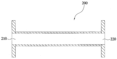
- the solidification apparatus 200 may include an inlet part through which the decomposition waste refrigerant gas discharged from a position where the waste refrigerant gas decomposed by plasma is discharged in an internal space of the plasma decomposition apparatus 100 may be introduced. It may be in the form of a cylindrical tube including a 210 and an outlet 220 facing the inlet 210.
- FIG. 6b shows another example of a solidifying apparatus 200 '.
- the solidification apparatus 200 ′ may have an inflow portion through which the decomposition waste refrigerant gas discharged from the position where the waste refrigerant gas decomposed by the plasma is discharged in the internal space of the plasma decomposition apparatus 100 is introduced.
- a cylindrical tubular shape including a 210 'and an outlet 220' facing the inlet 210 ', while the solidification apparatus 200 is discharged from the plasma decomposition apparatus 100 at the point where the decomposition waste refrigerant gas is discharged.
- the inlet portion 210 ′ includes a first extension region 211 ′ that extends the diameter of the solidifying apparatus 200 so as to have a diameter larger than the diameter of the solidification apparatus 200, and the discharge portion 220 ′ has a first extension region 211 ′.
- the decomposition waste refrigerant gas introduced into the internal space of the solidifying apparatus 200 passes through the internal space of the solidifying apparatus 200.
- the time required for the metal compound contained in or supplied from the solidification apparatus 200 to come into contact with the decomposition waste refrigerant may be increased.
- the metal compound is at least one metal atom selected from the group consisting of calcium (Ca), sodium (Na), manganese (Mn), iron (Fe), cobalt (Co), nickel (Ni) and copper (Cu) It consists of a compound of.
- the compound of such a metal atom may be in the form of an oxide, a nitride, a salt, or a metal itself and an alloy of such a metal atom.
- Calcium (Ca) may be provided as a calcium compound.
- CaCO 3 calcium carbonate (CaCO 3) , calcium oxide (CaO), calcium carbide (CaC 2 ), calcium hydroxide (Ca (OH) 2 ), calcium chloride (CaCl 2 ), calcium hypochlorite (Ca (ClO) 2 ) , Calcium sulfate (CaSO 4 ) or the like.
- Sodium (Na) may serve as the sodium compound.
- Manganese (Mn) can be provided as a manganese compound or artificially produced manganese.
- it may be provided as a manganese compound such as manganese dioxide (MnO 2 ), or as artificially produced manganese such as ferromanganese (FeMn) and silicomanganese (SiMn).
- Co can be provided as a cobalt compound.
- it may be provided with cobalt acetate (Co (C 2 H 4 O 2) 2 ), cobalt carbonate (CoCO 3 ), cobalt chloride (CoCl 2 ) and the like.
- Iron (Fe), nickel (Ni), copper (Cu) may be on their own or in the form of alloys or oxides or nitrides thereof.
- the metal compound is preferably configured to be positioned in the solidification apparatus 200 at a position where the temperature of the decomposition waste refrigerant gas discharged into the solidification apparatus 200 is 400 to 200 ° C.
- FIG. 7 is a cross-sectional view illustrating a state in which the plasma decomposition apparatus illustrated in FIG. 3A and the solidification apparatus illustrated in FIG. 4A are connected.
- the respective plasma decomposition apparatus 100 and the solidification apparatus 200 illustrated in FIGS. 3A and 4A are illustrated in FIG. 7. Connect as shown in. That is, the solidification apparatus 200 is connected to the inlet 210 to be in fluid communication with the discharge unit 150 located at the end of the second side portion 112 side of the internal reactor 120 of the plasma decomposition apparatus 100
- a structure located at the rear end of the decomposition apparatus 100 constitutes a decomposition and waste by-product solidification apparatus of the waste refrigerant according to an embodiment of the present invention.
- the decomposition waste refrigerant gas was discharged from the plasma decomposition apparatus into the solidification reactor to introduce the decomposition waste refrigerant gas into the solidification apparatus.
- the axial length of the solidifying apparatus was divided into a first region (# 1), a second region (# 2) and a third region (# 3), and then the temperature of the decomposition waste refrigerant gas was measured at the position of each region, The temperature of the first region was found to be about 800 ° C, the temperature of the second region was found to be about 550 ° C, and the temperature of the third region was found to be about 320 ° C.
- a stainless steel chip was pre-positioned as a metal compound containing iron (Fe) in the first region, the second region and the third region.
- FIG. 8 shows the results of measurement using EDX analysis equipment to determine whether fluorine adheres to the metal compound by reacting the decomposition waste refrigerant gas with the metal compound in each region of the solidification apparatus shown in FIG. 7 through Experimental Example 3. The graph shown.
- the degree of adhesion of fluorine (F) to the metal compound is close to 0%, from the second region (# 2).
- the amount of fluorine (F) attached to the metal compound is gradually increased toward the third region (# 3)
- the amount of fluorine (F) attached to the metal compound is increased to 60% or more in the third region (# 3). You can see that.
- FIG. 9 is a graph of respective regions showing the results of measurement using XRD analysis equipment to determine whether metal compounds combined with fluorine (F) are generated in each region of the solidification apparatus shown in FIG. 7 through Experimental Example 3.
- FIG. 9 is a graph of respective regions showing the results of measurement using XRD analysis equipment to determine whether metal compounds combined with fluorine (F) are generated in each region of the solidification apparatus shown in FIG. 7 through Experimental Example 3.
- FIG. 10A shows a photograph of the powder generated in the first region of the solidification apparatus shown in FIG. 7 and a transmission electron microscope photograph of the powder, through Experimental Example 3, and FIG. 10B shows the solidification shown in FIG. A photograph of the powder produced in the second region of the device and a transmission electron micrograph of the powder are shown, and FIG. 10C shows a photograph and powder of the powder produced in the third region of the solidification apparatus shown in FIG. 7 through Experimental Example 3 The transmission electron micrograph of a is shown.
- iron hydroxide Fe 2 O 3 is present in the second region # 2 in which the decomposition waste refrigerant gas has a temperature of about 550 ° C., and fluorine ( It can be seen that the metal compound FeF 3 combined with F) starts to form.
- the metal is combined with fluorine (F) having an improved surface than that of the powder, that is, the iron hydroxide (Fe 2 O 3 ) produced in the first region # 1. Since the compound (FeF 3 ) is generated, it was confirmed that the decomposition waste refrigerant gas was rapidly increased in the generation of the metal compound (FeF 3 ) combined with fluorine (F) at a temperature of about 600 ° C. or about 550 ° C.
- an optimum surface having an improved surface than that of the metal compound FeF 3 bonded to the powder, that is, the fluorine (F) generated in the second region # 2 is shown. Since metal compound (FeF 3 ) combined with fluorine (F) is produced, the decomposed waste refrigerant gas is combined with high purity fluorine (F) without generating metal oxide at a temperature of about 400 ° C or less or 350 ° C or less. It can be seen that the most preferable temperature range that can generate 3 ).
- the length of the solidification apparatus 200 is The temperature of the waste refrigerant gas decomposed in the internal space of the plasma decomposition apparatus 100 should have a length that may include an area of 600 ° C or less, preferably 400 ⁇ 200 ° C, whereby the waste refrigerant of the present invention
- the solidification step (S120) of the decomposition and by-product solidification method it is possible to implement that the decomposed waste refrigerant gas is in contact with the metal compound at a temperature of 600 ° C or less, preferably 400 ⁇ 200 ° C.
- the power of the plasma apparatus is 4 kW
- the air is injected at a flow rate of 40 lpm using air as the plasma supply gas
- Chlorodifluoromethane (CHClF 2 ) was injected at a flow rate of 5 lpm
- calcium hydroxide (Ca (OH) 2 ) as a metal compound was previously placed in the third region (# 3) of the solidifying apparatus 200 shown in FIG. 7. I was.
- FIG. 11A shows XRD data of calcium hydroxide (Ca (OH) 2 ) before chlorodifluoromethane (CHClF 2 ) was decomposed in Experimental Example 4, and the peak shown in the graph of FIG. 11A is calcium hydroxide (Ca (OH) 2 ). ) Is the intrinsic peak of.
- 11b shows XRD data of a metal compound formed by combining fluorine (F) and calcium hydroxide (Ca (OH) 2 ) after the decomposition of chlorodifluoromethane (CHClF 2 ) in Experimental Example 4; Under the conditions, chlorodifluoromethane (CHClF 2 ) was decomposed and fluorine (F) contained in the decomposed waste refrigerant gas was combined with calcium hydroxide (Ca (OH) 2 ) to confirm that the CaF 2 metal compound was produced.
- FIG. 12 is a block diagram conceptually showing the configuration of another embodiment of the decomposition and by-product solidification apparatus of the waste refrigerant of the present invention.
- the decomposition and by-product solidification apparatus of the waste refrigerant of the present invention may further include a heat exchange device (300).
- the heat exchanger 300 is positioned at a position where the waste refrigerant gas decomposed by the plasma decomposition device is discharged, and is configured to reduce the discharged waste refrigerant gas discharged.
- the shape of the heat exchange device 300 is not particularly limited, and any type of heat exchanger 300 may be connected to a position at which the waste refrigerant gas decomposed in the plasma decomposition apparatus 100 is discharged so as to reduce the temperature of the waste refrigerant gas decomposed.
- a heat exchanger in the form of a tube may be used in which the decomposed waste refrigerant gas may be cooled down while passing through the internal space.
- the heat exchange device 300 preferably reduces the temperature of the decomposition waste refrigerant gas discharged from the discharge portion of the plasma decomposition device 100 to a temperature of 600 ° C. or less, preferably 400 ° C. to 200 ° C.
- the decomposed waste refrigerant gas is introduced into the solidification apparatus 200, so that the metal compound accommodated in the solidification apparatus 200 or supplied from the outside is solidified. It can be located throughout the interior space of the device 200, it is possible to produce a metal compound of fluorine or chlorine in the entire interior space of the solidification device 200.
- the waste refrigerant and the by-product solidification apparatus of the present invention When the waste refrigerant and the by-product solidification apparatus of the present invention is used, the waste refrigerant is effectively decomposed using plasma, and fluorine or chlorine contained in the waste refrigerant gas decomposed by plasma is generated as a fluorine or chlorine metal compound. It can be solidified to produce high value-added metal compound resources, and solidification process that generates fluorine or chlorine metal compounds removes harmful components of fluorine and chlorine from waste refrigerants. Environmentally friendly gas emissions after treatment can be achieved.
Landscapes
- Engineering & Computer Science (AREA)
- Physics & Mathematics (AREA)
- Chemical & Material Sciences (AREA)
- Plasma & Fusion (AREA)
- Analytical Chemistry (AREA)
- Spectroscopy & Molecular Physics (AREA)
- Chemical Kinetics & Catalysis (AREA)
- Oil, Petroleum & Natural Gas (AREA)
- General Chemical & Material Sciences (AREA)
- Power Engineering (AREA)
- Mechanical Engineering (AREA)
- Thermal Sciences (AREA)
- General Engineering & Computer Science (AREA)
- Treating Waste Gases (AREA)
- Organic Low-Molecular-Weight Compounds And Preparation Thereof (AREA)
- Fire-Extinguishing Compositions (AREA)
- Processing Of Solid Wastes (AREA)
Abstract
폐냉매제의 분해 및 부산물 고형화 장치가 개시된다. 폐냉매제의 분해 및 부산물 고형화 장치는, 발생된 플라즈마에 의해 폐냉매제를 분해하거나 폐냉매제를 포함하는 가스를 플라즈마화하여 폐냉매제를 분해하도록 구성된 플라즈마 분해 장치로서, 상기 폐냉매제는 불소 또는 염소를 포함하는 염화불화탄소(CFC), 수소염화불화탄소(HCFC), 및 수소불화탄소(HFC) 중 어느 하나 이상의 화합물인 플라즈마 분해 장치; 및 상기 플라즈마 분해 장치에 의해 분해된 폐냉매제 가스가 토출되는 위치에 위치하고, 토출되는 분해 폐냉매제 가스가 유입되도록 구성되고, 금속화합물이 내부에 수용되거나 외부에서 공급되어 상기 금속화합물이 상기 토출된 분해 폐냉매제 가스와 접촉 반응하여, 불소 또는 염소의 금속화합물을 발생시키도록 구성된, 고형화 장치를 포함한다.
Description
본 발명은 폐냉매제의 분해 및 부산물 고형화 방법 및 그 장치에 관한 것으로, 더욱 상세하게는 폐냉매제를 분해하고, 폐냉매제가 분해된 후 발생되는 부산물을 고형화할 수 있는 폐냉매제의 분해 및 부산물 고형화 방법 및 그 장치에 관한 것이다.
냉동기나 자동차 등의 냉동 장치의 냉매로 사용되고 있는 것으로는 오존층을 파괴할 위험성이 있는 디클로로디플루오로메탄(R-12)이나, 공비 혼합 냉매의 R-12와 1, 1-디플루오로에탄(R-152a)으로 이루어진 R-500이나, 오존층을 파괴할 위험성은 적지만 지구 온난화 효과가 높은 염소기의 함유량을 감소시킨 대체 냉매인 클로로디플루오로메탄(HCFC-22)이나, 염소기를 함유하지 않은 냉매인 디플루오로메탄(HFC-32, R-32)이나, 트리플루오로메탄(HFC-23, R-23), 펜타플루오로에탄 (HFC-125, R-125), 1, 1, 1, 2-테트라플루오로에탄(HFC-134a, R-134a), 1, 1, 1-트리플루오로에탄(HFC-143a, R-143a)이나, 염소기와 수소를 함유하지 않은 플루오로카아본계 냉매(FC계 냉매), 프로판, 부탄, 펜탄 등의 가연성이 있는 탄화 수소류나 헬륨, 암모니아, 공기 등이 있다.
이러한 냉매는 자동차, 가전제품 등의 폐기에 따라 폐냉매는 적절한 처리없이 대기 중으로 방출되고 있다. 폐냉매가 적절한 처리 없이 대기중으로 방출되면 오존층 파괴나 지구 온난화의 주원인이 된다. 따라서 환경 문제가 점점 대두되는 현재 폐냉매를 적절히 처리하는 기술 개발이 이루어지고 있다.
예를 들면, 대한민국 공개특허번호 제2011-0023253호는 폐냉매를 고체 폐기물과 함께 연소하여 처리하는 장치 및 방법이 제시되고 있다.
그러나 이러한 기존 폐냉매 처리 방법은 대형 폐기물 소각로나 시멘트 소성로에 소량 투입하여 소각 처리하는 것으로, 폐냉매와 폐기물의 연소에 의해 다량의 연소가스가 발생할 뿐만 아니라 이산화질소 등 유해물질도 발생하며, 이를 제거하기 위해 다량의 물을 분무하여 응축시키고 별도의 세정기에서 유해물질을 제거함으로써 에너지 과다소비와 설비의 대형화가 요구되었다.
한편, 아르곤 플라즈마 아크, 마이크로파 플라즈마, 유도 결합 무선주파수 플라즈마, 질소 플라즈마 아크와 같은 플라즈마 토치를 이용하여 플라즈마 반응기 내에서 폐냉매를 처리하는 방법이 이용되고 있다.
이러한 종래의 폐냉매 처리 방법들을 이용하여 폐냉매를 분해하더라도 폐냉매는 불소(F) 및 염소(Cl)와 같은 할로겐 족 원소를 포함하고 있으므로 폐냉매의 분해 후 불소 및 염소를 포함하는 부산물이 발생되는데, 불소 및 염소와 같은 부산물을 포함하는 배출가스가 대기로 방출되지 않도록 폐냉매의 분해 단계에서 또는 그 이후 단계에서 불소 및 염소와 같은 부산물이 제거되기 위한 추가의 설비가 구비되어야 한다.
종래의 폐냉매 처리 방법에서는 폐냉매의 분해 단계에서 발생된 불소 및 염소와 같은 부산물은 주로 습식 스크러버에 의한 습식 공정을 통하여 처리되므로, 폐냉매 처리시 폐수가 발생되어 추가로 폐수를 수집하고 처리해야 하는 번거로움이 발생되었다.
또한 종래의 습식 스크러버를 통해 불소 및 염소와 같은 부산물을 처리하는 공정은 불소 및 염소의 처리 효율이 낮아서 불소 및 염소의 완전한 처리가 이루어지지 못하는 문제가 있었다.
본 발명은 기존의 폐냉매를 처리하는 방법의 단점인 폐냉매를 분해한 후 발생되는 불소 및 염소를 포함하는 부산물의 처리가 어렵다는 문제점을 해결할 수 있는 폐냉매제의 분해 및 부산물 고형화 방법 및 그 장치를 제공한다.
또한, 플라즈마를 이용하여 폐냉매제를 효과적으로 분해할 수 있도록 한 폐냉매제의 분해 및 부산물 고형화 방법 및 그 장치를 제공한다.
또한, 플라즈마에 의해 분해된 폐냉매제 가스에 포함된 불소 또는 염소를 불소 또는 염소의 금속화합물로 생성하여 고형화함으로써 고부가가치의 금속화합물의 자원을 생산할 수 있도록 한 폐냉매제의 분해 및 부산물 고형화 방법 및 그 장치를 제공한다.
일 측면으로서, 본 발명은 불소 또는 염소를 포함하는 염화불화탄소(CFC), 수소염화불화탄소(HCFC), 및 수소불화탄소(HFC) 중 어느 하나 이상의 화합물인 폐냉매제를 플라즈마에 의해 분해하거나 상기 폐냉매제를 포함하는 가스를 플라즈마화하여 상기 폐냉매제를 분해하는 단계; 및 상기 분해된 폐냉매제 가스를 금속화합물과 접촉 반응하여, 불소 또는 염소의 금속 화합물을 발생시키는 고형화 단계를 포함하는 폐냉매제의 분해 및 부산물 고형화 방법을 제공한다.
본 발명에서 사용되는 용어 "고형화"의 의미는, 폐냉매제로부터의 불소 또는 염소 원자가 금속화합물(예를 들어, NaOH, Ca(OH)2 또는 CaCO3)와 화학 반응을 통해 NaF 또는 CaCl2, CaF2와 같은 불소 또는 염소의 금속화합물로 형성됨을 의미하여, 분해된 가스로부터의 원자가 새로운 고체 화합물로 합성되어 쉽게 회수할 수 있도록 함을 의미한다.
상기 고형화 단계는, 상기 분해된 폐냉매제 가스가 600℃ 이하의 온도에서 상기 금속화합물과 접촉 반응하도록 한다. 이때, 금속화합물의 종류에 따라 600℃ 이하의 온도 내에서 온도는 제어될 수 있다.
바람직하게는 400~200℃의 온도에서 상기 금속화합물과 접촉 반응하도록 한다.
다른 측면으로서, 본 발명은, 폐냉매제의 분해 및 부산물 고형화 방법을 구현하기 위한 본 발명의 폐냉매제의 분해 및 부산물 고형화 장치를 제공한다.
본 발명의 폐냉매제의 분해 및 부산물 고형화 장치는, 발생된 플라즈마에 의해 폐냉매제를 분해하거나 폐냉매제를 포함하는 가스를 플라즈마화하여 폐냉매제를 분해하도록 구성된 플라즈마 분해 장치로서, 상기 폐냉매제는 불소 또는 염소를 포함하는 염화불화탄소(CFC), 수소염화불화탄소(HCFC), 및 수소불화탄소(HFC) 중 어느 하나 이상의 화합물인 플라즈마 분해 장치; 및 상기 플라즈마 분해 장치에 의해 분해된 폐냉매제 가스가 토출되는 위치에 위치하고, 토출되는 분해 폐냉매제 가스가 유입되도록 구성되고, 금속화합물이 내부에 수용되거나 외부에서 공급되어 상기 금속화합물이 상기 토출된 분해 폐냉매제 가스와 접촉 반응하여, 불소 또는 염소의 금속화합물을 발생시키도록 구성된, 고형화 장치를 포함한다.
상기 금속화합물은 상기 고형화 장치 내에서, 상기 고형화 장치 내로 토출되는 분해 폐냉매제 가스의 온도가 600℃ 이하, 바람직하게는 400~200℃인 위치에 위치하도록 구성된다.
상기 금속화합물은, 칼슘(Ca), 나트륨(Na), 망간(Mn), 철(Fe), 코발트(Co), 니켈(Ni) 및 구리(Cu)로 구성되는 군으로부터 선택되는 하나 이상의 금속 원자의 화합물일 수 있다. 예를 들어, 본 발명에서 사용되는 금속화합물이란 상기 원자를 포함하고 있는 화합물, 예컨대 Ca(OH)2, CaCO3 및 NaOH을 의미하며, 본 발명이 이러한 예에 특별히 한정되는 것은 아니다.
일 실시예로, 상기 플라즈마 분해 장치는, 원통형이고, 상기 원통의 축방향에 수직한 제1 측면부 및 상기 제1 측면부에 대향하는 제2 측면부를 포함하는 외부 반응기; 상기 외부 반응기보다 작은 직경을 갖는 원통형이고, 상기 제2 측면부를 향해 상기 외부 반응기 내로 삽입되어 있으며, 상기 외부 반응기 내부로 삽입된 부분은 상기 외부 반응기보다 짧은 길이로 상기 제1 측면부를 향해 연장되어 있는 내부 반응기; 상기 제1 측면부에 연결되고, 상기 외부 반응기의 축방향으로 플라즈마가 주입되도록 위치하고, 상기 내부 반응기의 삽입된 부분의 말단과 이격되어 있는 플라즈마 주입부; 상기 제2 측면부에 근접한 위치에서 상기 외부 반응기의 원주곡면에 연결되어 있고, 상기 외부 반응기의 내부로 폐냉매제 가스를 주입하기 위한 가스 주입부; 및 상기 내부 반응기의 상기 제2 측면부 쪽 말단에 위치한 토출부를 포함할 수 있다.
본 발명의 폐냉매제의 분해 및 부산물 고형화 방법의 다른 실시예로, 상기 폐냉매제를 분해하는 단계 이후에, 상기 분해된 폐냉매제 가스를 감온하는 단계를 더 포함할 수 있다. 이러한 경우, 상기 고온화 단계는, 감온된 상기 분해된 폐냉매제 가스를 금속화합물과 접촉 반응하여, 불소 또는 염소의 금속 화합물을 발생시킬 수 있다.
이러한 본 발명의 폐냉매제의 분해 및 부산물 고형화 방법 실시 형태를 구현하기 위해, 본 발명의 폐냉매제 분해 및 부산물 고형화 장치는, 상기 고형화 장치와 상기 플라즈마 분해 장치 사이에 연결된 열교환 장치를 더 포함하며, 상기 열교환 장치는, 상기 플라즈마 분해 장치에 의해 분해된 폐냉매제 가스가 토출되는 위치에 위치하고, 토출되는 분해 폐냉매제 가스를 감온하도록 구성되며, 상기 고형화 장치는, 상기 열교환 장치를 통과하여 상기 감온된 분해 폐냉매제 가스가 유입되도록 구성되고, 금속화합물이 내부에 수용되거나 외부에서 공급되어 상기 금속화합물이 상기 유입된 분해 폐냉매제 가스와 접촉 반응하여, 불소 또는 염소의 금속화합물을 발생시키도록 구성된다.
상기 열교환 장치를 통해, 상기 분해된 폐냉매제 가스가 600℃ 이하, 바람직하게는 400~200℃의 온도로 감온된다.
본 발명에 따른 폐냉매제의 분해 및 부산물 고형화 방법 및 그 장치는, 플라즈마를 이용하여 폐냉매제를 효과적으로 분해하고, 플라즈마에 의해 분해된 폐냉매제 가스에 포함된 불소 또는 염소를 불소 또는 염소의 금속화합물로 생성하여 고형화할 수 있으므로 고부가가치의 금속화합물의 자원을 생산할 수 있고, 불소 또는 염소의 금속화합물을 발생시키는 고형화 과정을 통해 폐냉매제에 포함된 불소 및 염소의 유해 성분이 제거되므로 플라즈마를 이용하여 폐냉매제 처리 후의 친환경적 가스의 배출이 이루어질 수 있는 이점이 있다.
도 1은 본 발명의 폐냉매제의 분해 및 부산물 고형화 방법의 공정을 나타낸 순서도이다.
도 2는 본 발명의 폐냉매제의 분해 및 부산물 고형화 장치를 개념적으로 나타낸 블록도이다.
도 3a는 본 발명의 폐냉매제의 분해 및 부산물 고형화 장치의 플라즈마 분해 장치의 일 실시예를 나타낸 도면이다.
도 3b는 도 3a에 도시된 플라즈마 분해 장치의 가스 주입부의 연결구조를 플라즈마 분해 장치의 횡단면으로 본 단면도이다.
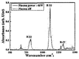
도 4a는 실험예 1에서 클로로디플루오르메탄(CHClF2)을 1 lpm의 유량으로 주입한 경우의 결과를 나타낸다.
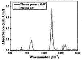
도 4b는 실험예 1에서 클로로디플루오르메탄(CHClF2)을 3 lpm의 유량으로 주입한 경우의 결과를 나타낸다.
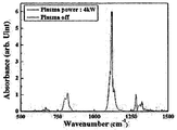
도 4c는 실험예 1에서 클로로디플루오르메탄(CHClF2)을 5 lpm의 유량으로 주입한 경우의 결과를 나타낸다.
도 5는 실험예 2에서 디클로로디플루오르메탄(CCl2F2)의 분해 결과를 나타낸다.
도 6a에는 고형화 장치의 일 예를 도시한다.
도 6b에는 고형화 장치의 다른 예를 도시한다.
도 7는 도 3a에 도시된 플라즈마 분해 장치 및 도 4a에 도시된 고형화 장치를 연결한 모습을 나타낸 단면도이다.
도 8은 실험예 3을 통해 도 7에 도시된 고형화 장치의 각각의 영역 내에서 분해 폐냉매제 가스가 금속화합물과 반응하여 불소가 금속화합물에 부착되는지 여부를 EDX 분석 장비를 이용하여 측정한 결과를 나타낸 그래프이다.
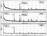
도 9는 실험예 3을 통해 도 7에 도시된 고형화 장치의 각각의 영역 내에서 불소(F)와 결합한 금속화합물의 생성 여부를 XRD 분석 장비를 이용하여 측정한 결과를 나타낸 각각의 영역의 그래프이다.
도 10a는 실험예 3을 통해 도 7에 도시된 고형화 장치의 제1 영역 내에서 생성된 분말의 사진 및 분말의 투과전자현미경 사진을 나타낸다.
도 10b는 실험예 3을 통해 도 7에 도시된 고형화 장치의 제2 영역 내에서 생성된 분말의 사진 및 분말의 투과전자현미경 사진을 나타낸다.
도 10c는 실험예 3을 통해 도 7에 도시된 고형화 장치의 제3 영역 내에서 생성된 분말의 사진 및 분말의 투과전자 현미경 사진을 나타낸다.
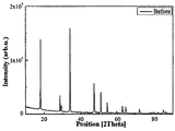
도 11a는 실험예 4에서 클로로디플루오르메탄(CHClF2)이 분해되기 전의 수산화칼슘(Ca(OH)2)의 XRD 데이터를 나타낸다.
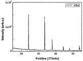
도 11b는 실험예 4에서 클로로디플루오르메탄(CHClF2)이 분해된 후 불소(F) 및 수산화칼슘(Ca(OH)2)이 결합하여 생성된 금속화합물의 XRD 데이터를 나타낸다.
도 12는 본 발명의 폐냉매제의 분해 및 부산물 고형화 장치의 다른 실시예의 구성을 개념적으로 나타낸 블록도이다.
이하, 첨부한 도면을 참조하여 본 발명의 실시예에 따른 폐냉매제의 분해 및 부산물 고형화 방법 및 그 장치에 대해 상세히 설명한다. 본 발명은 다양한 변경을 가할 수 있고 여러 가지 형태를 가질 수 있는 바, 특정 실시 예들을 도면에 예시하고 본문에 상세하게 설명하고자 한다. 그러나, 이는 본 발명을 특정한 개시 형태에 대해 한정하려는 것이 아니며, 본 발명의 사상 및 기술 범위에 포함되는 모든 변경, 균등물 내지 대체물을 포함하는 것으로 이해되어야 한다. 각 도면을 설명하면서 유사한 참조부호를 유사한 구성요소에 대해 사용하였다. 첨부된 도면에 있어서, 구조물들의 치수는 본 발명의 명확성을 기하기 위하여 실제보다 확대하여 도시한 것이다.
제1, 제2 등의 용어는 다양한 구성요소들을 설명하는데 사용될 수 있지만, 상기 구성요소들은 상기 용어들에 의해 한정되어서는 안 된다. 상기 용어들은 하나의 구성요소를 다른 구성요소로부터 구별하는 목적으로만 사용된다. 예를 들어, 본 발명의 권리 범위를 벗어나지 않으면서 제1 구성요소는 제2 구성요소로 명명될 수 있고, 유사하게 제2 구성요소도 제1 구성요소로 명명될 수 있다.
본 출원에서 사용한 용어는 단지 특정한 실시 예를 설명하기 위해 사용된 것으로, 본 발명을 한정하려는 의도가 아니다. 단수의 표현은 문맥상 명백하게 다르게 뜻하지 않는 한, 복수의 표현을 포함한다. 본 출원에서, "포함하다" 또는 "가지다" 등의 용어는 명세서 상에 기재된 특징, 숫자, 단계, 동작, 구성요소, 부분품 또는 이들을 조합한 것이 존재함을 지정하려는 것이지, 하나 또는 그 이상의 다른 특징들이나 숫자, 단계, 동작, 구성요소, 부분품 또는 이들을 조합한 것들의 존재 또는 부가 가능성을 미리 배제하지 않는 것으로 이해되어야 한다.
다르게 정의되지 않는 한, 기술적이거나 과학적인 용어를 포함해서 여기서 사용되는 모든 용어들은 본 발명이 속하는 기술 분야에서 통상의 지식을 가진 자에 의해 일반적으로 이해되는 것과 동일한 의미를 가지고 있다. 일반적으로 사용되는 사전에 정의되어 있는 것과 같은 용어들은 관련 기술의 문맥 상 가지는 의미와 일치하는 의미를 가지는 것으로 해석되어야 하며, 본 출원에서 명백하게 정의하지 않는 한, 이상적이거나 과도하게 형식적인 의미로 해석되지 않는다.
도 1은 본 발명의 폐냉매제의 분해 및 부산물 고형화 방법의 공정을 나타낸 순서도이다.
도 1을 참조하면, 본 발명의 폐냉매제의 분해 및 부산물 고형화 방법은, 폐냉매제를 플라즈마에 의해 분해하거나 상기 폐냉매제를 포함하는 가스를 플라즈마화하여 상기 폐냉매제를 분해하는 단계(S110); 및 상기 분해된 폐냉매제 가스를 금속화합물과 접촉 반응하여, 불소 또는 염소의 금속 화합물을 발생시키는 고형화 단계(S120)를 포함한다. 상기 고형화 단계(S120)는, 상기 분해된 폐냉매제 가스가 600℃ 이하의 온도에서 상기 금속화합물과 접촉 반응하도록 한다. 이때, 금속화합물의 종류에 따라 600℃ 이하의 온도 내에서 온도는 제어될 수 있다. 바람직하게는 400~200℃의 온도에서 상기 금속화합물과 접촉 반응하도록 한다.
이러한 본 발명의 폐냉매제의 분해 및 부산물 고형화 방법을 구현하기 위해, 아래에서 설명되는 본 발명의 폐냉매제의 분해 및 부산물 고형화 장치가 이용된다.
도 2는 본 발명의 폐냉매제의 분해 및 부산물 고형화 장치를 개념적으로 나타낸 블록도이다.
도 2를 참조하면, 본 발명의 폐냉매제의 분해 및 부산물 고형화 장치는, 플라즈마 분해 장치(100) 및 고형화 장치(200)를 포함한다.
플라즈마 분해 장치(100)는 발생된 플라즈마에 의해 폐냉매제를 분해하거나 폐냉매제를 포함하는 가스를 플라즈마화하여 폐냉매제를 분해하도록 구성된다.
이러한 플라즈마 분해 장치(100) 내로 주입되는 플라즈마는 전자파 플라즈마일 수 있다. 전자파 플라즈마를 주입하기 위해 플라즈마 토치 발생 장치가 이용될 수 있다. 플라즈마 토치 발생 장치에 대해서는 본원 특허의 발명자의 이전 등록 특허인, 대한민국 특허공보 10-0394994호가 참조된다. 이 특허는 본원에 그대로 참조로서 통합된다.
상기 폐냉매제는 불소 또는 염소를 포함하는 염화불화탄소(CFC), 수소염화불화탄소(HCFC), 및 수소불화탄소(HFC) 중 어느 하나 이상의 화합물이다.
플라즈마 분해 장치(100)의 형태에는 특별한 제한은 없으며, 중공관 형태이고, 플라즈마를 주입할 수 있는 플라즈마 주입부, 폐냉매제 가스를 주입할 수 있는 가스 주입부 및 플라즈마에 의해 분해된 폐냉매제 가스가 토출되는 토출부의 구성을 갖는 형태라면 모두 가능하다.
도 3a는 본 발명의 폐냉매제의 분해 및 부산물 고형화 장치의 플라즈마 분해 장치의 일 실시예를 나타낸 도면이다.
도 3a을 참조하면, 플라즈마 분해 장치(100)는 외부 반응기(110), 내부 반응기(120), 플라즈마 주입부(130), 가스 주입부(140) 및 토출부(150)를 포함할 수 있다.
외부 반응기(110)는 반응기의 외관을 형성하는 부분이다. 외부 반응기(110)는 원통형이고, 원통의 축방향에 수직한 제1 측면부(111) 및 제1 측면부(111)에 대향하는 제2 측면부(112)를 포함한다. 제1 측면부(111) 및 제2 측면부(112)는 원형 플레이트 형태일 수 있다. 예를 들면, 제1 측면부(111) 및 제2 측면부(112)는 상기 원통의 직경에 대응하는 원 형상일 수 있고, 또는 상기 원통의 직경보다 큰 원 형상일 수 있다.
내부 반응기(120)는 원통형이고, 원통은 외부 반응기(110)보다 작은 직경을 갖는다. 이러한 내부 반응기(120)는 외부 반응기(110)의 내부로 삽입된다.
이때, 내부 반응기(120)는 제2 측면부(112)를 통해 외부 반응기(110) 내로 삽입된다. 예를 들면, 내부 반응기(120)의 일단부가 제2 측면부(112)의 내면에 고정되고 다른 일단부는 제2 측면부(112)로부터 제1 측면부(111)를 향해 연장될 수 있다. 이때, 내부 반응기(120)의 길이는 외부 반응기(110)의 전체 길이보다 짧은 길이로 연장된다. 이하 설명의 편의를 위하여 제2 측면부(112)의 내면에 고정된 단부를 '고정단(120a)'이라 칭하고, 제1 측면부(111)를 향해 연장된 단부를 '자유단(120b)'이라 칭한다. 내부 반응기(120)의 자유단(120b)은 내부 반응기(120)의 길이가 외부 반응기(110)의 길이보다 짧은 길이를 가짐에 따라 외부 반응기(110)의 제1 측면부(111)로부터 일정 거리 이격된다. 자유단(120b)의 이격된 거리는 내부 반응기(120)의 길이를 변경하는 것에 의해 조절 가능하다.
이와 같이 내부 반응기(120)가 외부 반응기(110) 내부에 위치함에 따라 본 발명의 반응기는 이중관 구조를 갖는다. 이때, 내부 반응기(120)는 외부 반응기(110)의 직경보다 작은 직경을 가짐에 따라 내부 반응기(120)의 외면과 외부 반응기(110)의 내면은 일정 거리 이격되며, 이에 의해 내부 반응기(120)와 외부 반응기(110)의 사이에는 유체의 이동이 가능한 공간부가 형성된다. 또한 내부 반응기(120)는 외부 반응기(110)의 내부에 위치하므로 내부 반응기(120)의 내부는 외부 반응기(110) 내에 또 다른 공간부를 형성하게 된다. 이러한 경우, 외부 반응기(110) 및 내부 반응기(120) 사이의 공간부는 폐냉매제 가스가 이동할 수 있는 가스 이동공간(161)일 수 있고, 내부 반응기(120)의 내부의 공간부는 플라즈마가 주입되어 플라즈마와 폐냉매제 가스가 반응하는 플라즈마 반응공간(162)일 수 있다. 여기서, 내부 반응기(120)의 내부는 고온의 플라즈마와 폐냉매제 가스가 반응하는 공간으로서 필요에 따라 내화재(예를 들면, 석영관)가 삽입될 수 있다.
한편, 가스 이동공간(161) 및 플라즈마 반응공간(162)은 서로 통하여 있다. 즉, 앞서 언급한 바와 같이 내부 반응기(120)는 외부 반응기(110)보다 짧은 길이를 갖는 것에 의해 자유단(120b)이 제1 측면부(111)와 일정 거리 이격됨에 따라 내부 반응기(120)를 사이에 둔 각각의 가스 이동공간(161) 및 플라즈마 반응공간(162)은 제1 측면부(111)를 향해 열려있게 되고, 이에 의해 가스 이동공간(161) 및 플라즈마 반응공간(162)은 서로 통하게 된다.
이러한 가스 이동공간(161) 및 플라즈마 반응공간(162)으로는 폐냉매제 가스 및 플라즈마가 주입된다. 폐냉매제 가스는 가스 주입부(140)를 통해 주입되고, 플라즈마는 플라즈마 주입부(130)를 통해 주입된다.
플라즈마 주입부(130)는 외부 반응기(110)의 제1 측면부(111)에 연결된다. 이때, 플라즈마 주입부(130)는 외부 반응기(110)의 축방향과 평행하게 위치한다. 이에 의해 플라즈마 주입부(130)는 플라즈마가 외부 반응기(110) 및 내부 반응기(120)의 축방향을 따라 주입되도록 한다. 플라즈마의 주입을 위해 플라즈마 주입부(130)는 플라즈마 발생부와 연결될 수 있다. 플라즈마 발생부는 플라즈마를 생성하는 부분이다. 예를 들면, 플라즈마 토치일 수 있다. 플라즈마 발생부로부터 나온 플라즈마는 내부 반응기(120)의 축방향을 따라 내부 반응기(120)의 내부로 주입된다. 이러한 플라즈마 주입부(130)의 직경은 외부 반응기(110) 및 내부 반응기(120)의 직경보다 작다. 내부 반응기(120)의 직경보다 작은 직경을 가짐에 따라 플라즈마 주입부(130)를 통해 주입되는 플라즈마는 내부 반응기(120)의 내부로 용이하게 주입된다. 한편 플라즈마는 플라즈마 주입부(130)에 가까운 플라즈마 영역의 경우 고온의 플라즈마 영역이고 플라즈마 주입부(130)로부터 멀어질수록 저온의 플라즈마 영역이다.
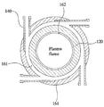
도 3b는 도 3a에 도시된 플라즈마 분해 장치의 가스 주입부의 연결구조를 플라즈마 분해 장치의 횡단면으로 본 단면도이다.
도 3b를 참조하면, 반응가스 주입부(140)는 제2 측면부(112)에 근접한 위치에서 외부 반응기(110)의 원주곡면에 연결되어, 플라즈마 주입부(130)의 반대편에 위치한다. 이때, 가스 주입부(140)는 외부 반응기(110)의 내면의 접선 방향으로 설치된다. 이에 의해 가스 주입부(140)를 통해 외부 반응기(110)의 내부로 주입되는 폐냉매제 가스는 스월(swirl) 형태로 주입이 가능하다. 즉, 스월 형태로 주입되는 폐냉매제 가스는 외부 반응기(110)의 내면을 따라 선회하면서 주입될 수 있다. 가스 주입부(140)는 하나 또는 그 이상의 개수로 설치될 수 있다.
한편 가스 주입부(140)를 통해 외부 반응기(110)의 내부로 주입된 폐냉매제 가스는 가스 이동공간(161) 및 플라즈마 반응공간(162)을 거치면서 플라즈마 처리(분해)되어 플라즈마 분해 장치(100)의 외부로 배출된다.
토출부(150)는 외부 반응기(110)의 내부로 주입되어 플라즈마 처리에 의해 분해된 폐냉매제 가스가 배출되기 위한 개구이다. 이러한 토출부(150)는 플라즈마 반응공간(162)을 통과하는 폐냉매제 가스가 용이하게 배출될 수 있도록 내부 반응기(120)의 제2 측면부(112) 쪽 말단, 즉 고정단(120a)에 형성될 수 있다.
한편, 가스 이동공간(161)으로 주입된 폐냉매제 가스는 플라즈마 반응공간(162)을 향해 주입되는 플라즈마 중 폐냉매제 가스의 반응효율이 높은 고온의 플라즈마 영역에 빠르게 섞일 수 있는 구조를 갖는 것이 바람직하다. 이를 위해, 본 발명의 일 실시예에 따른 플라즈마 분해 장치는 외부 반응기(110)의 내부에 가스 유도부(170)를 설계하였다.
가스 유도부(170)는 가스 이동공간(161)에서 이동하는 폐냉매제가스의 진행방향의 앞에 위치한다. 이때, 가스 유도부(170)는 절두된 원추 형상의 내부 공간을 갖는다. 절두된 원추 형상은 제1 측면부(111)의 내면 중 중심 일부면(a)을 윗면으로 하며, 외부 반응기(110)의 횡단면(b)을 아랫면으로 하도록 형성된다. 따라서 가스 유도부(170)는 외부 반응기(110)의 내부로부터 플라즈마 주입부(130)를 향해 좁아지는 소정의 각도로 테이퍼진 형태가 된다.
이러한 가스 유도부(170)는 다양한 형태로 설계될 수 있다. 예를 들면, 외부 반응기(110)의 내부에 절두된 원추 형상의 내부 공간을 갖는 성형부재를 고정 설치하는 것에 의해 구성될 수 있다.
이러한 가스 유도부(170)는 앞서 언급된 바와 같이, 가스 이동공간(161)에서 이동하는 폐냉매제 가스의 진행방향의 앞에 위치하고, 외부 반응기(110)의 내부로부터 플라즈마 주입부(130)를 향해 테이퍼진 형태를 이루고 있으므로 가스 이동공간(161)에서 플라즈마 주입부(130)를 향해 진행하는 폐냉매제 가스가 플라즈마 주입부(130)에 근접하게 도달하면 가스를 플라즈마 주입부(130)를 향해 빠르게 유도하게 된다.
한편 이러한 가스 유도부(170)가 설치되는 경우, 내부 반응기(120)의 삽입된 부분의 길이는, 내부 반응기(120)의 자유단(120b)이 가스 유도부(170)의 원추 형상의 내부 공간에 위치하는 길이일 수 있다.
이하에서는 본 발명의 일 실시예에 따른 플라즈마 분해 장치의 내부로 주입된 폐냉매제 가스의 처리과정을 설명한다.
플라즈마 주입부(130)를 통해 플라즈마가 내부 반응기(120)의 축방향을 따라 주입된다. 플라즈마는 내부 반응기(120)의 내부인 플라즈마 반응공간(162)으로 주입된다.
폐냉매제 가스는 가스 주입부(140)를 통해 가스 이동공간(161)으로 주입된다. 이때, 가스 주입부(140)는 외부 반응기(110)의 내면의 접선 방향으로 설치되어 있으므로 스월 형태로 주입된다.
스월 형태로 주입된 폐냉매제 가스는 가스 이동공간(161) 내에서 외부 반응기(110)의 내면을 따라 선회하면서 플라즈마 주입부(130)를 향해 진행된다.
진행하는 폐냉매제 가스가 플라즈마 주입부(130)에 근접한 위치까지 도달하면 폐냉매제 가스는 가스 유도부(170)에 의해 플라즈마 주입부(130)를 향해 빠르게 이동하며, 이에 의해 플라즈마 주입부(130)를 통해 주입되는 플라즈마에 빠르게 섞이게 된다. 이때, 가스 유도부(170)는 외부 반응기(110)의 내면으로부터 플라즈마 주입부(130)를 향해 좁아지는 형태로 테이퍼져 있으므로 폐냉매제 가스는 플라즈마 주입부(130)에 근접한 고온의 플라즈마 영역에 빠르게 섞일 수 있다.
플라즈마와 섞인 폐냉매제 가스는 플라즈마가 플라즈마 반응공간(162) 내로 주입되므로 플라즈마와 반응하면서 플라즈마 반응공간(162)으로 이동한다.
플라즈마 반응공간(162) 내에서 폐냉매제 가스는 플라즈마와 계속하여 반응하면서 내부 반응기(120)의 축방향을 따라 토출부(150)를 향해 진행한다. 이 과정에서 플라즈마 반응공간(162) 내에는 플라즈마와 폐냉매제 가스가 반응하면서 2차 플라즈마 발생이 이루어지고 이에 의해 폐냉매제 가스는 분해된다. 분해된 폐냉매제 가스는 토출부(150)에 연결된 고형화 장치(200)의 내부로 배출된다.
이러한 폐냉매제 가스의 분해 과정에서 외부 반응기(110)의 내부로 스월 형태로 주입되는 폐냉매제 가스는 폐냉매제 가스의 반응기 내에서의 체류시간을 증대 시키고, 이에 의해 플라즈마 분해 장치(100)의 공랭의 역할을 하여 반응기의 열 손실을 최소화할 수 있다.
또한, 폐냉매제 가스가 고온의 플라즈마 영역에 빠르게 섞이게 됨에 따라 폐냉매제 가스의 처리 유량 및 폐냉매제 가스의 처리 효율이 증대될 수 있다.
예시한 플라즈마 분해 장치(100)를 이용하는 경우, 플라즈마 분해 장치(100)의 내부로 주입된 폐냉매제 가스의 분해 효과가 높았다. 이는, 아래의 실험예 1을 통해 증명된다.
실험예 1
실험을 위해, 전자파 플라즈마 발생장치 및 도 3a에 예시된 장치를 사용하여, 전자파 플라즈마 발생장치의 파워를 4kW로 하고, 플라즈마 공급 가스로 에어(air)를 사용하여 에어를 40 lpm(liter per minute)의 유량으로 주입하였다. 이러한 조건하에서 클로로디플루오르메탄(CHClF2)를 각각 1 lpm, 3 lpm, 5 lpm의 유량으로 주입하여, 클로로디플루오르메탄(CHClF2)의 각각의 주입 유량에 따른 클로로디플루오르메탄(CHClF2)의 분해 결과를 측정하였다.
도 4a는 실험예 1에서 클로로디플루오르메탄(CHClF2)을 1 lpm의 유량으로 주입한 경우의 결과를 나타내며, 도 4b는 실험예 1에서 클로로디플루오르메탄(CHClF2)을 3 lpm의 유량으로 주입한 경우의 결과를 나타내며, 도 4c는 실험예 1에서 클로로디플루오르메탄(CHClF2)을 5 lpm의 유량으로 주입한 경우의 결과를 나타낸다. 도 4a 내지 도 4c의 그래프를 통해 확인할 수 있는 바와 같이, 붉은색 피키는 플라즈마로 분해하기 전의 클로로디플루오르메탄(CHClF2)의 고유 피크이며, 검은색 피키는 플라즈마로 분해한 후의 피크로서, 각각의 경우 모두 클로로디플루오르메탄(CHClF2)이 완전히 분해되었음을 확인할 수 있다.
실험예 2
실험예 1과 동일한 장치를 사용하고, 전자파 플라즈마 발생장치의 파워를 4kW로 하고, 플라즈마 공급 가스로 에어(air)를 사용하여 에어를 40 lpm(liter per minute)의 유량으로 주입하고, 디클로로디플루오르메탄(CCl2F2)을 1 lpm의 유량으로 주입하였고, 그 디클로로디플루오르메탄(CCl2F2)의 분해 결과를 측정하였다.
도 5는 실험예 2에서 디클로로디플루오르메탄(CCl2F2)의 분해 결과를 나타낸다. 도 5에서 보는 바와 같이, 디클로로디플루오르메탄(CCl2F2)은 완전히 분해됨을 확인할 수 있다.
고형화 장치(200)는 상기 분해된 폐냉매제 가스가 유입되도록 구성되고, 금속화합물을 내부에 수용하거나 외부에서 공급되어 상기 금속화합물이 상기 유입된 분해된 폐냉매제 가스와 접촉 반응하여, 불소 또는 염소의 금속화합물을 발생시키도록 구성된다.
앞서 언급한 바와 같이, 고형화 장치(200)는 금속화합물이 내부에 수용되거나 외부에서 공급되는데, 금속화합물이 내부에 수용되는 경우는 분해 폐냉매제 가스가 고형화 장치(200)의 내부로 유입되기 전에 미리 수용되어 있는 상태를 말하며, 금속화합물이 외부에서 공급되는 경우는 분해 폐냉매제 가스가 고형화 장치(200)의 내부로 유입되기 전에 고형화 장치(200)의 외부로부터 내부로 공급되는 상태 또는 분해 폐냉매제 가스가 고형화 장치(200)의 내부로 유입될 때 고형화 장치(200)의 외부로부터 내부로 공급되는 상태를 말한다.
이러한 고형화 장치(200)의 형태에는 특별한 제한은 없으며, 금속화합물을 수용할 수 있고 플라즈마 분해 장치(100)로부터 토출되는 분해된 폐냉매제 가스를 수용할 수 있는 내부공간을 갖는 형태라면 모두 가능할 것이다.
도 6a에는 고형화 장치(200)의 일 예가 도시되어 있다. 도 6a를 참조하면, 일 예로, 고형화 장치(200)는 플라즈마 분해 장치(100)의 내부공간에서 플라즈마에 의해 분해된 폐냉매제 가스가 토출되는 위치로부터 토출되는 분해 폐냉매제 가스가 유입되는 유입부(210) 및 유입부(210)에 대향하는 배출부(220)를 포함하는 원통형의 관 형태일 수 있다.
도 6b에는 고형화 장치(200')의 다른 예가 도시되어 있다. 도 6b를 참조하면, 다른 예로, 고형화 장치(200')는 플라즈마 분해 장치(100)의 내부공간에서 플라즈마에 의해 분해된 폐냉매제 가스가 토출되는 위치로부터 토출되는 분해 폐냉매제 가스가 유입되는 유입부(210') 및 유입부(210')에 대향하는 배출부(220')를 포함하는 원통형의 관 형태이면서, 고형화 장치(200)가 플라즈마 분해 장치(100)에서 분해 폐냉매제 가스가 토출되는 위치의 직경보다 큰 직경을 갖도록 유입부(210')는 고형화 장치(200)의 직경을 확장시키는 제1 확장영역(211')을 포함하고, 배출부(220')는 제1 확장영역(211')에 대칭되게 대향하는 제2 확장영역(221')을 포함할 수 있다.
도 6b와 같은 고형화 장치(200) 형태의 경우 고형화 장치(200)의 직경이 확장되므로 고형화 장치(200)의 내부공간으로 유입된 분해 폐냉매제 가스가 고형화 장치(200)의 내부공간을 통과하는 시간을 지연시킬 수 있으며, 이에 따라, 고형화 장치(200)의 내부에 수용되거나 외부에서 공급된 금속화합물이 분해 폐냉매제와 접촉하는 시간이 증가될 수 있다.
한편, 금속화합물은 칼슘(Ca), 나트륨(Na), 망간(Mn), 철(Fe), 코발트(Co), 니켈(Ni) 및 구리(Cu)로 구성되는 군으로부터 선택되는 하나 이상의 금속 원자의 화합물로 구성된다. 이러한 금속 원자의 화합물이란, 이러한 금속원자의 산화물, 질화물, 염, 또는 금속자체 및 합금 형태일 수 있다.
칼슘(Ca)은 칼슘 화합물로서 제공될 수 있다. 예를 들면, 탄산칼슘(CaCO3), 산화칼슘(CaO), 탄화칼슘(CaC2), 수산화칼슘(Ca(OH)2), 염화칼슘(CaCl2), 하이포아염소산칼슘(Ca(ClO)2), 황산칼슘(CaSO4) 등으로 제공될 수 있다.
나트륨(Na)은 나트륨 화합물로서 제공될 수 있다. 예를 들면, 규산 나트륨(Na2SiO3), 로릴 황산 나트륨(C12H25OH), 산화 나트륨(Na2O), 수산화 나트륨(NaOH), 질산 나트륨(NaNO3), 탄산 나트륨(Na2CO3), 탄산 수소 나트륨(NaHCO3), 플루오린화 나트륨(NaF), 황산 나트륨(Na2SO4), 황화 수소 나트륨(NaHS) 등으로 제공될 수 있다.
망간(Mn)은 망간 화합물 또는 인위적으로 생산된 망간으로서 제공될 수 있다. 예를 들면, 이산화망간(MnO2)과 같은 망간 화합물로 제공되거나, 페로망간(FeMn) 및 실리코망간(SiMn)과 같은 인위적으로 생산된 망간으로서 제공될 수 있다.
코발트(Co)는 코발트 화합물로서 제공될 수 있다. 예를 들면, 아세트산 코발트(Co(C2H4O2)2), 탄산코발트(CoCO3), 염화코발트(CoCl2) 등으로 제공될 수 있다.
철(Fe), 니켈(Ni), 구리(Cu)는 그 자체로 또는 합금 형태 또는 이의 산화물 또는 질화물 형태일 수 있다.
이러한 금속화합물은 바람직하게는 고형화 장치(200) 내에서, 고형화 장치(200) 내로 토출되는 분해 폐냉매제 가스의 온도가 400~200℃인 위치에 위치하도록 구성된다.
이는, 분해 폐냉매제 가스의 온도가 약 600℃ 이하에서 불소 또는 염소 화합물의 합성이 두드러지게 발생되기 시작하며, 약 300℃ 이하에서는 투입된 금속화합물의 산화물이 급감하면서, 불소 또는 염소 화합물의 순도가 높아진다. 이를 증명하기 위해, 아래의 실험예 3 및 실험예 4와 같이 실험하였고, 실험을 위해 도 3에 도시된 형태로 본 발명의 폐냉매제의 분해 및 부산물 고형화 장치를 구성하여 실험을 실시하였다.
도 7는 도 3a에 도시된 플라즈마 분해 장치 및 도 4a에 도시된 고형화 장치를 연결한 모습을 나타낸 단면도이다.
폐냉매제를 플라즈마를 이용하여 분해하고 플라즈마에 의해 분해된 폐냉매제 가스를 금속화합물과 반응시키기 위해, 도 3a 및 도 4a에서 예시된 각각의 플라즈마 분해 장치(100) 및 고형화 장치(200)를 도 7에서 보여지는 바와 같이 연결하였다. 즉, 고형화 장치(200)는 유입부(210)가 플라즈마 분해 장치(100)의 내부 반응기(120)의 제2 측면부(112) 쪽 말단에 위치한 토출부(150)와 유체 소통 가능하도록 연결되어 플라즈마 분해 장치(100)의 후단에 위치하는 구조로 본 발명의 일 실시예에 따른 폐냉매제의 분해 및 부산물 고형화 장치를 구성하였다.
실험예 3
- 플라즈마 분해 장치로부터 고형화 반응기의 내부로 분해 폐냉매제 가스를 토출하여 고형화 장치 내로 분해 폐냉매제 가스를 유입시켰다.
- 고형화 장치의 축방향 길이를 제1 영역(#1), 제2 영역(#2) 및 제3 영역(#3)으로 나눈 후 각각의 영역의 위치에서 분해 폐냉매제 가스의 온도를 측정하였고, 제1 영역의 온도는 약 800℃로 확인되고, 제2 영역의 온도는 약 550℃로 확인되고, 제3 영역의 온도는 약 320℃로 확인되었다.
- 상기 제1 영역, 상기 제2 영역 및 상기 제3 영역에 철(Fe)을 포함하는 금속화합물로서 스테인레스 스틸 칩(stainless steel chip)을 미리 위치시켰다.
도 8은 실험예 3을 통해 도 7에 도시된 고형화 장치의 각각의 영역 내에서 분해 폐냉매제 가스가 금속화합물과 반응하여 불소가 금속화합물에 부착되는지 여부를 EDX 분석 장비를 이용하여 측정한 결과를 나타낸 그래프이다.
도 8의 그래프에 나타난 바와 같이, 제1 영역(#1) 및 제2 영역(#2)에서는 불소(F)가 금속화합물과 부착되는 정도가 0%에 가깝고, 제2 영역(#2)으로부터 제3 영역(#3)으로 갈수록 금속화합물에 부착되는 불소(F)의 양이 점차 증가하면서 제3 영역(#3)에서는 금속화합물에 부착되는 불소(F)의 양이 60% 이상으로 증가된 것을 확인할 수 있다.
도 9는 실험예 3을 통해 도 7에 도시된 고형화 장치의 각각의 영역 내에서 불소(F)와 결합한 금속화합물의 생성 여부를 XRD 분석 장비를 이용하여 측정한 결과를 나타낸 각각의 영역의 그래프이다.
도 10a는 실험예 3을 통해 도 7에 도시된 고형화 장치의 제1 영역 내에서 생성된 분말의 사진 및 분말의 투과전자현미경 사진을 나타내고, 도 10b는 실험예 3을 통해 도 7에 도시된 고형화 장치의 제2 영역 내에서 생성된 분말의 사진 및 분말의 투과전자현미경 사진을 나타내고, 도 10c는 실험예 3을 통해 도 7에 도시된 고형화 장치의 제3 영역 내에서 생성된 분말의 사진 및 분말의 투과전자 현미경 사진을 나타낸다.
도 9의 제1 영역(#1)의 그래프에 나타난 바와 같이, 분해 폐냉매제 가스가 약 800℃의 온도를 갖는 제1 영역(#1)에서는 수산화철(Fe2O3)이 존재할 뿐, 불소(F)와 결합한 금속화합물(FeF3)이 존재하지 않는 것을 확인할 수 있다.
따라서 제1 영역(#1)에서는 도 10a에 나타낸 바와 같은 분말, 즉 표면이 거친 수산화철(Fe2O3)만이 생성되므로 분해 폐냉매제 가스가 약 800℃의 높은 온도인 경우에는 불소(F)와 결합한 금속화합물(FeF3)을 생성하기에 적합하지 않은 온도범위인 것을 알 수 있다.
도 9의 제2 영역(#2)의 그래프에 나타난 바와 같이, 분해 폐냉매제 가스가 약 550℃의 온도를 갖는 제2 영역(#2)에서는 수산화철(Fe2O3)이 존재하며, 불소(F)와 결합한 금속화합물(FeF3)이 생성되기 시작하는 것을 확인할 수 있다.
따라서 제2 영역(#2)에서는 도 10b에 나타낸 바와 같이 분말, 즉 제1 영역(#1)에서 생성된 수산화철(Fe2O3)의 표면보다 개선된 표면을 갖는 불소(F)와 결합한 금속화합물(FeF3)이 생성되므로 분해 폐냉매제 가스가 약 600℃ 또는 약 550℃의 온도에서부터 불소(F)와 결합한 금속화합물(FeF3)이 발생됨이 급격히 늘어남을 확인할 수 있었다.
도 9의 제3 영역(#3)의 그래프에 나타난 바와 같이, 분해 폐냉매제 가스가 약 320℃의 온도를 갖는 제3 영역(#3)에서는 불소(F)와 결합한 금속화합물(FeF3)만이 존재하는 것을 확인할 수 있다. 이는, 제3 영역(#3)에서 분해 폐냉매제 가스에 포함된 불소(F)가 철(Fe)을 포함하는 금속화합물과 완전히 결합된 것을 의미한다.
따라서 제3 영역(#3)에서는 도 10c에 나타낸 바와 같이 분말, 즉 제2 영역(#2)에서 생성된 불소(F)와 결합한 금속화합물(FeF3)의 표면보다 개선된 표면을 갖는 최적의 불소(F)와 결합한 금속화합물(FeF3)이 생성되므로 분해 폐냉매제 가스가 약 400℃ 이하 또는 350℃ 이하의 온도에서 금속산화물의 발생이 없는 높은 순도의 불소(F)와 결합한 금속화합물(FeF3)을 생성할 수 있는 가장 바람직한 온도범위인 것을 확인할 수 있다.
실험예 3에서는 불소(F)와 결합한 금속화합물(FeF3)이 생성되는 것에 대해 설명하였으나, 염소의 경우도 동일하며, 염소(Cl)와 결합한 금속화합물(FeF3)의 생성을 위해 염소와의 결합이 이루어질 수 있는 금속화합물을 고형화 장치(200) 내에 공급하면 가능하다.
이러한 실험예 3을 통해 확인된 바와 같이 분해 폐냉매제 가스가 600℃ 이하 바람직하게는 400~200℃의 온도일 때 불소 또는 염소의 금속화합물을 원활하게 발생시킬 수 있으므로 고형화 장치(200)의 길이는 플라즈마 분해 장치(100)의 내부공간에서 분해된 폐냉매제 가스의 온도가 600℃ 이하 바람직하게는 400~200℃의 온도인 영역을 포함할 수 있는 길이를 가져야 하며, 이에 의해 본 발명의 폐냉매제의 분해 및 부산물 고형화 방법의 고형화 단계(S120)에서, 분해된 폐냉매제 가스가 600℃ 이하 바람직하게는 400~200℃의 온도에서 상기 금속화합물과 접촉 반응하는 것을 구현할 수 있다.
실험예 4
실험을 위해, 전자파 플라즈마 발생장치 및 도 7에 예시된 장치를 사용하여,라즈마 장치의 파워를 4kW로 하고, 플라즈마 공급 가스로 에어(air)를 사용하여 에어를 40 lpm의 유량으로 주입하고, 클로로디플루오르메탄(CHClF2)을 5 lpm의 유량으로 주입하였고, 도 7에 도시된 고형화 장치(200)의 제3 영역(#3)에 금속화합물로서 수산화칼슘(Ca(OH)2)를 미리 위치시켰다.
도 11a는 실험예 4에서 클로로디플루오르메탄이(CHClF2)이 분해되기 전의 수산화칼슘(Ca(OH)2)의 XRD 데이터를 나타내는 것으로서, 도 11a의 그래프에 나타난 피크는 수산화칼슘(Ca(OH)2)의 고유 피크이다.
도 11b는 실험예 4에서 클로로디플루오르메탄(CHClF2)이 분해된 후 불소(F) 및 수산화칼슘(Ca(OH)2)이 결합하여 생성된 금속화합물의 XRD 데이터를 나타내는 것으로서, 실험예 4의 조건으로 클로로디플루오르메탄(CHClF2)을 분해하고 분해된 폐냉매제 가스에 포함된 불소(F)가 수산화칼슘(Ca(OH)2)과 결합하여 CaF2의 금속화합물이 생성되었음을 확인할 수 있다.
도 12는 본 발명의 폐냉매제의 분해 및 부산물 고형화 장치의 다른 실시예의 구성을 개념적으로 나타낸 블록도이다.
도 12를 참조하면, 본 발명의 폐냉매제의 분해 및 부산물 고형화 장치는 열교환 장치(300)를 더 포함할 수 있다.
열교환 장치(300)는 플라즈마 분해 장치에 의해 분해된 폐냉매제 가스가 토출되는 위치에 위치하고, 상기 토출되는 분해된 폐냉매제 가스를 감온하도록 구성된다.
이러한 열교환 장치(300)의 형태에는 특별한 제한은 없으며, 플라즈마 분해 장치(100)에서 분해된 폐냉매제 가스가 토출되는 위치에 연결되어 분해된 폐냉매제 가스의 온도를 감온할 수 있는 형태라면 모두 가능하다. 예를 들면, 분해된 폐냉매제 가스가 내부공간을 통과하면서 감온될 수 있는 튜브(Tube)형태의 열교환 장치가 사용될 수 있다.
실험예 3 및 실험예 4를 통해 설명한 바와 같이 플라즈마 분해 장치(100)를 통해 분해된 폐냉매제 가스가 600℃ 이하 바람직하게는 400~200℃의 온도일 때 불소 또는 염소를 포함하는 금속화합물이 원활히 발생될 수 있으므로 열교환 장치(300)는 플라즈마 분해 장치(100)의 토출부로부터 토출되는 분해 폐냉매제 가스의 온도를 600℃ 이하 바람직하게는 400~200℃의 온도로 감온하는 것이 바람직하다.
열교환 장치(300)를 이용하여 분해 폐냉매제 가스의 온도를 감온하게 되면, 감온된 분해 폐냉매제 가스가 고형화 장치(200) 내로 유입되므로 고형화 장치(200) 내에 수용되거나 외부에서 공급되는 금속화합물은 고형화 장치(200)의 내부공간 전체에 위치될 수 있고, 고형화 장치(200)의 내부공간 전체에서 불소 또는 염소의 금속화합물의 생성이 가능해질 수 있다.
이러한 본 발명의 폐냉매제의 분해 및 부산물 고형화 장치를 이용하면, 플라즈마를 이용하여 폐냉매제를 효과적으로 분해하고, 플라즈마에 의해 분해된 폐냉매제 가스에 포함된 불소 또는 염소를 불소 또는 염소의 금속화합물로 생성하여 고형화할 수 있으므로 고부가가치의 금속화합물의 자원을 생산할 수 있고, 불소 또는 염소의 금속화합물을 발생시키는 고형화 과정을 통해 폐냉매제에 포함된 불소 및 염소의 유해 성분이 제거되므로 플라즈마를 이용하여 폐냉매제 처리 후의 친환경적 가스의 배출이 이루어질 수 있다.
제시된 실시예들에 대한 설명은 임의의 본 발명의 기술 분야에서 통상의 지식을 가진 자가 본 발명을 이용하거나 또는 실시할 수 있도록 제공된다. 이러한 실시예들에 대한 다양한 변형들은 본 발명의 기술 분야에서 통상의 지식을 가진 자에게 명백할 것이며, 여기에 정의된 일반적인 원리들은 본 발명의 범위를 벗어남이 없이 다른 실시예들에 적용될 수 있다. 그리하여, 본 발명은 여기에 제시된 실시예들로 한정되는 것이 아니라, 여기에 제시된 원리들 및 신규한 특징들과 일관되는 최광의의 범위에서 해석되어야 할 것이다.
Claims (14)
- 발생된 플라즈마에 의해 폐냉매제를 분해하거나 폐냉매제를 포함하는 가스를 플라즈마화하여 폐냉매제를 분해하도록 구성된 플라즈마 분해 장치로서, 상기 폐냉매제는 불소 또는 염소를 포함하는 염화불화탄소(CFC), 수소염화불화탄소(HCFC), 및 수소불화탄소(HFC) 중 어느 하나 이상의 화합물인 플라즈마 분해 장치; 및상기 플라즈마 분해 장치에 의해 분해된 폐냉매제 가스가 토출되는 위치에 위치하고, 토출되는 분해 폐냉매제 가스가 유입되도록 구성되고, 금속화합물이 내부에 수용되거나 외부에서 공급되어 상기 금속화합물이 상기 토출된 분해 폐냉매제 가스와 접촉 반응하여, 불소 또는 염소의 금속화합물을 발생시키도록 구성된, 고형화 장치를 포함하는,폐냉매제의 분해 및 부산물 고형화 장치.
- 제1항에 있어서,상기 금속화합물은 상기 고형화 장치 내에서, 상기 고형화 장치 내로 토출되는 분해 폐냉매제 가스의 온도가 600℃ 이하인 위치에 위치하도록 구성되는,폐냉매제의 분해 및 부산물 고형화 장치.
- 제1항에 있어서,상기 금속화합물은 상기 고형화 장치 내에서, 상기 고형화 장치 내로 토출되는 분해 폐냉매제 가스의 온도가 400~200℃인 위치에 위치하도록 구성되는,폐냉매제의 분해 및 부산물 고형화 장치.
- 제1항에 있어서,상기 고형화 장치와 상기 플라즈마 분해 장치 사이에 연결된 열교환 장치를 더 포함하며,상기 열교환 장치는, 상기 플라즈마 분해 장치에 의해 분해된 폐냉매제 가스가 토출되는 위치에 위치하고, 토출되는 분해 폐냉매제 가스를 감온하도록 구성되며,상기 고형화 장치는, 상기 열교환 장치를 통과하여 상기 감온된 분해 폐냉매제 가스가 유입되도록 구성되고, 금속화합물이 내부에 수용되거나 외부에서 공급되어 상기 금속화합물이 상기 유입된 분해 폐냉매제 가스와 접촉 반응하여, 불소 또는 염소의 금속화합물을 발생시키도록 구성된,폐냉매제의 분해 및 부산물 고형화 장치.
- 제1항에 있어서,상기 금속화합물은, 칼슘(Ca), 나트륨(Na), 망간(Mn), 철(Fe), 코발트(Co), 니켈(Ni) 및 구리(Cu)로 구성되는 군으로부터 선택되는 하나 이상의 금속 원자의 화합물인,폐냉매제의 분해 및 부산물 고형화 장치.
- 제4항에 있어서,상기 열교환 장치를 통해, 상기 분해된 폐냉매제 가스가 600℃ 이하의 온도로 감온되는,폐냉매제의 분해 및 부산물 고형화 장치.
- 제4항에 있어서,상기 열교환 장치를 통해, 상기 분해된 폐냉매제 가스가 400~200℃의 온도로 감온되는,폐냉매제의 분해 및 부산물 고형화 장치.
- 제1항에 있어서,상기 플라즈마 분해 장치는,원통형이고, 상기 원통의 축방향에 수직한 제1 측면부 및 상기 제1 측면부에 대향하는 제2 측면부를 포함하는 외부 반응기;상기 외부 반응기보다 작은 직경을 갖는 원통형이고, 상기 제2 측면부를 향해 상기 외부 반응기 내로 삽입되어 있으며, 상기 외부 반응기 내부로 삽입된 부분은 상기 외부 반응기보다 짧은 길이로 상기 제1 측면부를 향해 연장되어 있는 내부 반응기;상기 제1 측면부에 연결되고, 상기 외부 반응기의 축방향으로 플라즈마가 주입되도록 위치하고, 상기 내부 반응기의 삽입된 부분의 말단과 이격되어 있는 플라즈마 주입부;상기 제2 측면부에 근접한 위치에서 상기 외부 반응기의 원주곡면에 연결되어 있고, 상기 외부 반응기의 내부로 폐냉매제 가스를 주입하기 위한 가스 주입부; 및상기 내부 반응기의 상기 제2 측면부 쪽 말단에 위치한 토출부를 포함하는,폐냉매제의 분해 및 부산물 고형화 장치.
- 불소 또는 염소를 포함하는 염화불화탄소(CFC), 수소염화불화탄소(HCFC), 및 수소불화탄소(HFC) 중 어느 하나 이상의 화합물인 폐냉매제를 플라즈마에 의해 분해하거나 상기 폐냉매제를 포함하는 가스를 플라즈마화하여 상기 폐냉매제를 분해하는 단계; 및상기 분해된 폐냉매제 가스를 금속화합물과 접촉 반응하여, 불소 또는 염소의 금속 화합물을 발생시키는 고형화 단계를 포함하는,폐냉매제의 분해 및 부산물 고형화 방법.
- 제9항에 있어서,상기 고형화 단계는, 상기 분해된 폐냉매제 가스가 600℃ 이하의 온도에서 상기 금속화합물과 접촉 반응하도록 하는,폐냉매제의 분해 및 부산물 고형화 방법.
- 제9항에 있어서,상기 고형화 단계는, 상기 분해된 폐냉매제 가스가 400~200℃의 온도에서 상기 금속화합물과 접촉 반응하도록 하는,폐냉매제의 분해 및 부산물 고형화 방법.
- 제9항에 있어서,상기 폐냉매제를 분해하는 단계 이후에,상기 분해된 폐냉매제 가스를 감온하는 단계를 더 포함하고,상기 고형화 단계는, 감온된 상기 분해된 폐냉매제 가스를 금속화합물과 접촉 반응하여, 불소 또는 염소의 금속 화합물을 발생시키는,폐냉매제의 분해 및 부산물 고형화 방법.
- 제12항에 있어서,상기 분해된 폐냉매제 가스를 감온하는 단계는, 상기 분해된 폐냉매제 가스를 600℃ 이하의 온도로 감온시키는,폐냉매제의 분해 및 부산물 고형화 방법.
- 제12항에 있어서,상기 분해된 폐냉매제 가스를 감온하는 단계는, 상기 분해된 폐냉매제 가스를 400~200℃의 온도로 감온시키는,폐냉매제의 분해 및 부산물 고형화 방법.
Applications Claiming Priority (2)
| Application Number | Priority Date | Filing Date | Title |
|---|---|---|---|
| KR1020150035298A KR101654085B1 (ko) | 2015-03-13 | 2015-03-13 | 폐냉매제의 분해 및 부산물 고형화 방법 및 그 장치 |
| KR10-2015-0035298 | 2015-03-13 |
Publications (1)
| Publication Number | Publication Date |
|---|---|
| WO2016148459A1 true WO2016148459A1 (ko) | 2016-09-22 |
Family
ID=56918961
Family Applications (1)
| Application Number | Title | Priority Date | Filing Date |
|---|---|---|---|
| PCT/KR2016/002508 Ceased WO2016148459A1 (ko) | 2015-03-13 | 2016-03-14 | 폐냉매제의 분해 및 부산물 고형화 방법 및 그 장치 |
Country Status (2)
| Country | Link |
|---|---|
| KR (1) | KR101654085B1 (ko) |
| WO (1) | WO2016148459A1 (ko) |
Citations (3)
| Publication number | Priority date | Publication date | Assignee | Title |
|---|---|---|---|---|
| JPH08332339A (ja) * | 1995-06-09 | 1996-12-17 | Chichibu Onoda Cement Corp | 有機化合物分解装置 |
| KR20010106040A (ko) * | 2000-05-20 | 2001-11-29 | 박동화 | 직류 열플라즈마를 이용한 cfc 또는 pfc의분해·처리방법 |
| JP2003260334A (ja) * | 2002-03-11 | 2003-09-16 | Toshio Goto | 被処理ガスの固体化方法および材料の処理方法 |
-
2015
- 2015-03-13 KR KR1020150035298A patent/KR101654085B1/ko active Active
-
2016
- 2016-03-14 WO PCT/KR2016/002508 patent/WO2016148459A1/ko not_active Ceased
Patent Citations (3)
| Publication number | Priority date | Publication date | Assignee | Title |
|---|---|---|---|---|
| JPH08332339A (ja) * | 1995-06-09 | 1996-12-17 | Chichibu Onoda Cement Corp | 有機化合物分解装置 |
| KR20010106040A (ko) * | 2000-05-20 | 2001-11-29 | 박동화 | 직류 열플라즈마를 이용한 cfc 또는 pfc의분해·처리방법 |
| JP2003260334A (ja) * | 2002-03-11 | 2003-09-16 | Toshio Goto | 被処理ガスの固体化方法および材料の処理方法 |
Non-Patent Citations (2)
| Title |
|---|
| HONG, YONG CHEOL ET AL.: "Volatile Organic Compound Elimination Improved on Inlet Position of Vortex Gas in Microwave Torch Plasma.", IEEE TRANSACTION ON PLASMA SCIENCE, vol. 42, no. 7, July 2014 (2014-07-01), pages 1982 - 1984, XP011552528 * |
| KIM, GWAN TAE ET AL.: "Decomposition of HFCs using Steam Plasma.", ASIAN JOURNAL OF ATMOSPHERIC ENVIRONMENT., vol. 29, no. 1, February 2013 (2013-02-01), pages 27 - 37, XP055312623 * |
Also Published As
| Publication number | Publication date |
|---|---|
| KR101654085B1 (ko) | 2016-09-05 |
Similar Documents
| Publication | Publication Date | Title |
|---|---|---|
| US20100107871A1 (en) | Fluoride ion cleaning method | |
| WO2018026134A1 (ko) | 질소산화물, 염화불화탄소류, 수소염화불화탄소류, 수소불화탄소류 및 과불화화합물을 포함하는 복합 폐가스의 통합 처리 시스템 | |
| JP2012507629A (ja) | フッ化物イオン洗浄のシステム及び装置 | |
| EP2794506A2 (en) | Aggregates | |
| US20110186419A1 (en) | Apparatus for synthesizing nano particles, and method for synthesizing the nano particles using the same | |
| JP2002346377A (ja) | 熱プラズマによるセラミック又は金属の球状粉末の製造方法および装置 | |
| TW201343240A (zh) | 用於PFCs廢氣處理之渦流電漿反應器 | |
| KR101654085B1 (ko) | 폐냉매제의 분해 및 부산물 고형화 방법 및 그 장치 | |
| WO2008072467A1 (ja) | アスベストの溶融方法及びそのための装置 | |
| KR19990017420A (ko) | 플라즈마를 이용한 난분해성 가스 처리방법 | |
| JP2003168594A (ja) | 高周波熱プラズマ装置 | |
| JP6386792B2 (ja) | 溶射材料 | |
| CN108840349A (zh) | 一种超细无定形硼粉的制备方法 | |
| KR102917972B1 (ko) | 듀얼 액체금속 반응기 및 이를 이용한 화합물 제조방법 | |
| CN1189146A (zh) | 切割耐火材料 | |
| JP2017019699A (ja) | 溶射材料 | |
| JP4875233B2 (ja) | 廃棄物中の金属の利用方法 | |
| JP2006056993A (ja) | 溶射補修材の平滑化 | |
| Murphy | Thermal plasma destruction of ozone-depleting substances: technologies and chemical equilibrium, chemical kinetic and fluid dynamic modelling | |
| JP2005120420A (ja) | ボーキサイト溶解残渣の処理方法 | |
| JP2011184707A (ja) | 還元スラグの硫黄除去方法 | |
| JP2002080853A (ja) | 赤熱コークスの消火方法 | |
| JP2001253764A (ja) | フロン分解物を利用した建築材料の製造方法 | |
| JP4004859B2 (ja) | 有機ハロゲン化合物の無害化処理方法 | |
| KR20260011312A (ko) | 알루미늄 용탕에 함유된 리튬 제거 장치 및 방법 |
Legal Events
| Date | Code | Title | Description |
|---|---|---|---|
| 121 | Ep: the epo has been informed by wipo that ep was designated in this application |
Ref document number: 16765215 Country of ref document: EP Kind code of ref document: A1 |
|
| NENP | Non-entry into the national phase |
Ref country code: DE |
|
| 122 | Ep: pct application non-entry in european phase |
Ref document number: 16765215 Country of ref document: EP Kind code of ref document: A1 |