WO2016147369A1 - ゲート設備の巻上機軸の構造 - Google Patents
ゲート設備の巻上機軸の構造 Download PDFInfo
- Publication number
- WO2016147369A1 WO2016147369A1 PCT/JP2015/058175 JP2015058175W WO2016147369A1 WO 2016147369 A1 WO2016147369 A1 WO 2016147369A1 JP 2015058175 W JP2015058175 W JP 2015058175W WO 2016147369 A1 WO2016147369 A1 WO 2016147369A1
- Authority
- WO
- WIPO (PCT)
- Prior art keywords
- hoisting machine
- machine shaft
- door body
- gate
- shaft
- Prior art date
- Legal status (The legal status is an assumption and is not a legal conclusion. Google has not performed a legal analysis and makes no representation as to the accuracy of the status listed.)
- Ceased
Links
Images


Classifications
-
- E—FIXED CONSTRUCTIONS
- E02—HYDRAULIC ENGINEERING; FOUNDATIONS; SOIL SHIFTING
- E02B—HYDRAULIC ENGINEERING
- E02B7/00—Barrages or weirs; Layout, construction, methods of, or devices for, making same
- E02B7/20—Movable barrages; Lock or dry-dock gates
-
- E—FIXED CONSTRUCTIONS
- E02—HYDRAULIC ENGINEERING; FOUNDATIONS; SOIL SHIFTING
- E02B—HYDRAULIC ENGINEERING
- E02B7/00—Barrages or weirs; Layout, construction, methods of, or devices for, making same
- E02B7/20—Movable barrages; Lock or dry-dock gates
- E02B7/26—Vertical-lift gates
Definitions
- the present invention relates to the structure of a hoisting machine shaft of a gate facility, and in particular, to a gate facility such as a hydroelectric power plant that opens and closes the door body by transmitting the power of the hoisting machine to the door body via the hoisting machine shaft. Further, the present invention relates to the structure of the connecting portion of the hoisting machine shaft of the gate equipment that is effective for the trial operation for the inspection of the gate equipment.
- gate equipment such as hydroelectric power plants.
- gate equipment that opens and closes the door body by transmitting the power of the hoisting machine to the door body through the hoisting machine shaft. It has been.
- Patent Document 1 describes a technique related to a hoisting machine inspection method.
- This inspection method is an inspection method for a hoisting machine having a gear mechanism to which grease is applied, and a wear test that reproduces the wear of the gear mechanism using grease that has been oxidized in advance is performed.
- the grease is collected from the vicinity of the gear, and the occurrence and progress of gear wear are estimated from the collected grease state without being disassembled.
- the present invention has been made in view of the above-described conventional problems, and in a trial operation in the inspection of a gate facility such as a hydroelectric power plant, not only the operation of the hoisting machine but also the operation of the hoisting machine shaft is confirmed. It is another object of the present invention to provide a structure of a hoisting machine shaft for a gate facility that can reduce the cost for improvement.
- the present invention employs the following means. That is, the present invention provides a door body that can be moved up and down at a gate and opens and closes the gate, a hoisting machine shaft that can be moved up and down connected to the upper part of the door body, and a hoisting machine that moves up and down the hoisting machine shaft
- the hoisting machine shaft structure of the gate equipment provided with the hoisting machine shaft without transmitting the power of the hoisting machine shaft to the door body to the connecting portion of the hoisting machine shaft with the door body.
- a power transmission means for providing a predetermined play width in which the ascending is increased is provided.
- the power of the hoisting machine shaft is not transmitted to the door body while the door body is blocking the gate. Since the hoisting machine shaft can be raised and lowered without raising and lowering the door within the range of the predetermined play width in which only the hoisting machine shaft rises, not only the operation of the hoisting machine but also the hoisting machine shaft is normal. It is possible to confirm whether or not to operate. Therefore, a trial operation with an actual operation from the hoisting machine to the hoisting machine shaft can be performed, the range of the actual operation by the trial operation can be expanded, and the reliability of equipment maintenance can be improved.
- the power transmission means is inserted into the elongated hole extending in the ascending / descending direction of the hoisting machine shaft provided at the upper portion of the door body, and moves along the elongated hole.
- a connecting pin capable of contacting the upper and lower ends of the long hole, and connecting the hoisting machine shaft to the connecting pin, so that the connecting pin moves between the upper and lower ends of the long hole. Is defined as the predetermined play width.
- a long hole extending in the ascending / descending direction of the hoisting machine shaft is provided in the upper part of the door body, and a connecting pin is inserted into the long hole, and the hoisting machine is wound on the connecting pin. Since the machine shaft is simply connected, the actual operation of the hoisting machine shaft can be realized at a low cost simply by making a simple modification to the connecting part of the existing hoisting machine shaft to the door.
- the present invention can be applied to existing gate facilities.
- the long hole may be provided in a support fitting provided at an upper portion of the door body.
- the hoisting machine shaft of the gate equipment of the present invention since it has a simple structure in which a support fitting having a long hole is provided in the upper part of the door body, it is possible to make an existing improvement without adding a major improvement to the gate equipment.
- the actual operation of the hoisting machine shaft can be made possible by simply adding a simple improvement to the connecting part of the hoisting machine shaft to the door.
- the power transmission means includes an elastic member that is provided at an upper portion of the door body, and that is elastically deformable in an ascending / descending direction of the hoisting machine shaft, and a connecting pin connected to the elastic member.
- a range in which the elastic member is elastically deformed by connecting the hoisting machine shaft to the connecting pin may be the predetermined play width.
- the hoisting machine shaft of the gate equipment of the present invention a simple configuration is provided in which an elastic member that can be elastically deformed in the ascending / descending direction of the hoisting machine shaft and a connecting pin connected to the elastic member are provided on the upper part of the door body. Therefore, the actual operation of the hoisting machine shaft can be made possible by making a simple modification to the connecting portion of the existing hoisting machine shaft with the door body without making a major improvement to the gate equipment.
- the elastic member may be provided on a support fitting provided on an upper portion of the door body.
- the hoisting machine shaft of the gate equipment of the present invention since it has a simple structure in which an elastic member is provided on the support fitting provided on the upper part of the door body, without adding a significant improvement to the gate equipment, The actual operation of the hoisting machine shaft can be achieved by simply adding a simple improvement to the connecting part of the existing hoisting machine shaft with the door.
- the hoisting machine may be an electric or manual hoisting machine.
- the applicable range is expanded. Can do.
- the power of the hoisting machine shaft is maintained with the door closed. Since the hoisting machine shaft can be raised within a predetermined play width without being transmitted to the door body, not only the operation of the hoisting machine but also whether the hoisting machine shaft operates normally or not. Confirmation can be made. Therefore, a trial operation with an actual operation from the hoisting machine to the hoisting machine shaft can be performed, the range of the actual operation by the trial operation can be expanded, and the reliability of equipment maintenance can be improved.
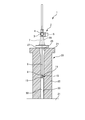
- FIG. 2 is a sectional view taken along line AA in FIG. 1.
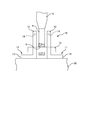
- FIG. 2 is an enlarged view of a portion A in FIG. 1, and is an explanatory view showing a state in which a connecting pin is in contact with a lower end of a long hole.
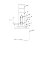
- FIG. 4 is a side view of FIG. 3.
- FIG. 2 is an enlarged view of a portion A in FIG. 1, and is an explanatory view showing a state in which a connecting pin is in contact with an upper end of a long hole.
- FIG. 1 to 5 show an embodiment of the structure of a hoisting machine shaft of a gate equipment according to the present invention.
- the structure of the hoisting machine shaft of the gate equipment of this embodiment is such as a hydroelectric power plant that opens and closes the door body 30 by transmitting the power of the hoisting machine 2 to the door body 30 via the hoisting machine shaft 6. It is applied to the gate facility 1 such as a water channel, and enables the trial operation for the inspection of the gate facility 1 to be effectively performed.
- the gate facility 1 is provided at a connection portion with a river in a waterway and an opening 26 of the gate 20 so as to be movable up and down, and opens and closes the opening 26 of the gate 20.
- a hoisting machine shaft 6 that moves up and down integrally with the door body 30, and a hoisting machine 2 that moves up and down the hoisting machine shaft 6.
- the gate 20 includes a floor slab 21 provided at the bottom of the connection portion with the river in the waterway, a pair of gate pillars 22 and 22 provided in parallel with a space above the floor slab 21, and upper ends of both gate pillars 22 and 22. It forms a gate shape composed of a ceiling end 24 laid in between, and an opening 26 that communicates a river and a water channel in a portion surrounded by the floor slab 21, both gate pillars 22, 22 and the ceiling end 24. Is provided.
- Supporting grooves 23 extending in the vertical direction are respectively provided on the mutually opposing surfaces of the pair of gate pillars 22, and the door body 30 is supported between the supporting grooves 23, 23 so as to be movable up and down.
- An insertion hole 25 penetrating the top end 24 in the vertical direction is provided at the center of the top end 24, and a hoisting machine shaft 6 to be described later is inserted through the insertion hole 25.
- a base 27 made of a pair of steel materials such as C-shaped steel is integrally provided on both sides of the insertion hole 25 in the upper central portion of the top end 24, and a tapered cylindrical casing 28 is integrally formed on the base 27.
- a hoisting machine 2 to be described later is provided on the upper portion of the casing 28.
- the door body 30 has a plate shape formed by combining various steel materials, and both side portions are slidably engaged in both support grooves 23 and 23 of both gate pillars 22 and 22.
- the opening part 26 of the gate 20 can be opened and closed by sliding the door body 30 up and down along the both support grooves 23 and 23 of both the gate pillars 22 and 22 and moving the door body 30 up and down.
- the hoisting machine 2 is an electric spindle type hoisting machine, and includes an electric motor 3, a speed reducer 4 having an input shaft connected to a drive shaft of the electric motor 3, and a worm gear or the like on an output shaft of the speed reducer 4. It is comprised from the internal thread 5 connected through this.
- the hoisting machine 2 is provided on the upper part of the casing 28 so that the female screw 5 is rotatably arranged on the upper part of the casing 28 above the top end 24.
- the hoisting machine shaft 6 has a rod shape in which a male screw 7 that meshes with the female screw 5 of the hoisting machine 2 is provided on the peripheral surface, and the upper end of the hoisting machine shaft 6 is engaged with the female screw 5 of the hoisting machine 2.
- the lower end projects from the hoisting machine 2 and the lower end is inserted through the insertion hole 25 of the casing 28 and the top end 24 and is connected to the upper portion 31 of the door body 30 via the power transmission means 10.
- the lower end portion of the hoisting machine shaft 6 is provided with a flat plate-like connecting portion 8 formed by chamfering both surfaces thereof, and in the central portion near the lower end of the connecting portion 8, A pin insertion hole 9 through which a connecting pin 15 described later is inserted is provided.
- the power transmission means 10 includes a pair of support fittings 11 and 11 fixed at a distance from the center of the upper surface of the door body 30 and a lower end portion of the hoisting machine shaft 2. It is comprised from the connection pin 14 connected between the support metal fittings 11 and 11. FIG.
- the support fitting 11 has an L-shaped cross section formed of a steel material such as angle steel, and is provided integrally with the flat support portion 12 and one end of the support portion 12 so as to be orthogonal to the support portion 12. And flat leg portions 13.
- the support bracket 11 has a leg portion 13 fixed to the upper portion of the door body 30 by a fixing means such as a bolt or welding so that the support portion 12 rises upward from the upper surface of the door body 30.
- a long hole 14 extending in the vertical direction is provided in a central portion of the support portion 12 of the support metal 11 so as to penetrate therethrough.
- the connecting portion 8 at the lower end of the hoisting machine shaft 6 is inserted between the both supporting portions 12 and 12 of the both supporting metal parts 11 and 11, and the long hole 14 of both the supporting portions 12 and 12 and the pin insertion hole 9 of the hoisting machine shaft 6.
- the lower end portion of the hoisting machine shaft 6 can be connected to the door body 30 via the support fitting 11 of the power transmission means 10 and the connection pin 15.
- the connecting pin 15 is connected to the pin insertion hole 9 of the connecting portion 8 of the hoisting machine shaft 6 at the center in the longitudinal direction by means such as screwing and fitting, and both ends are connected to both the support brackets 11 and 11.
- the support portions 12 and 12 are configured to protrude outward by a predetermined length from the outer surface.
- the door body 30 By connecting the lower end portion of the hoisting machine shaft 6 between the both support parts 12 and 12 of both the support metal fittings 11, the door body 30 can be raised and lowered following the raising and lowering of the hoisting machine shaft 6.
- the part 26 can be opened and closed.
- the long holes 14 and 14 of both the support parts 12 and 12 of both the support metal fittings 11 and 11 are formed so that it may extend in an up-down direction. For this reason, the long holes 14 and 14 are set to have a play width a of the hoisting machine shaft 6 when the hoisting machine shaft 6 is raised while maintaining the state in which the door body 30 closes the opening 26 of the gate 20. it can.
- a limit switch detects that the connecting pin 15 has come into contact with the upper ends of the long holes 14 and 14 and the electric motor 3 of the hoisting machine 2 is stopped by a signal from the limit switch.
- the connecting portion 8 at the lower end of the hoisting machine shaft 6 is connected to the upper part 31 of the door body 30 by the power transmission means 10,
- the connecting pin 15 that connects the hoisting machine shaft 6 to the support metal fittings 11, 11 is brought into contact with the upper and lower ends of the long holes 14, 14 of the support metal fittings 11, 11 of the power transmission means 10. Is transmitted to the door body 30, and the power from the hoisting machine shaft 6 is not transmitted to the door body 30 within the range in which the connecting pin 15 moves between the upper and lower ends of the long holes 14, 14. It can be set as the play width a which only the upper machine shaft 6 raises / lowers.
- the existing hoisting machine shaft 6 since it is the simple structure which provided the long hole 14 in the support metal fitting 11 of the power transmission means 10 which provided the connection part 8 of the lower end of the hoisting machine shaft 6 in the upper surface of the door body 30, the existing hoisting machine shaft 6 The actual operation of the hoisting machine shaft 6 can be realized by simply making a simple improvement in the connecting portion with the door body 30, and the present invention can be applied to existing gate equipment at low cost.
- the long hole 14 is provided in the support portion 12 of the support fitting 11, but a protrusion protruding upward is integrally provided on the upper portion 31 of the door body 30, and the long hole 14 is provided in this protrusion. You may comprise.
- an elastic member that can be elastically deformed in the vertical direction is provided on the support portion 12 of the support fitting 11, and a connecting pin 15 is connected to the elastic member so that the elastic deformation range of the elastic member in the vertical direction is reduced. It is good also as the play width from which the motive power of 6 is not transmitted to the door body 30.
- the present invention is applied to an electric spindle hoisting machine.
- the present invention may be applied to a manual spindle hoisting machine.
Landscapes
- Engineering & Computer Science (AREA)
- Structural Engineering (AREA)
- General Engineering & Computer Science (AREA)
- Mechanical Engineering (AREA)
- Civil Engineering (AREA)
- Barrages (AREA)
Abstract
【課題】 巻上機軸の動力が扉体に伝達されない遊び幅を持たせることにより、扉体を開操作することなく、巻上機軸の動作の確認を行うことを可能にする。 【解決手段】 ゲートを開閉する扉体30と、扉体30の上部に連結される昇降可能な巻上機軸6と、巻上機軸6を昇降させる巻上機とを備えたゲート設備の巻上機軸の構造であって、巻上機軸6の扉体30との連結部8に、巻上機軸6の動力が扉体30に伝達されることなく巻上機軸6が上昇する所定の遊び幅を持たせる動力伝達手段10を設ける。動力伝達手段10は、扉体30の上部に設けられる巻上機軸6の昇降方向に延びる長孔14と、長孔14に挿着されるとともに、長孔14に沿って移動可能、かつ、長孔14の上下端に当接可能な連結ピン15とを備え、連結ピン15に巻上機軸6を連結することにより、連結ピン15が長孔14の上下端間を移動する範囲内を所定の遊び幅とした。
Description
本発明は、ゲート設備の巻上機軸の構造に関し、特に、巻上機の動力を巻上機軸を介して扉体に伝達させることにより、扉体を開閉させる水力発電所等のゲート設備に適用され、ゲート設備の点検のための試運転業務に有効なゲート設備の巻上機軸の連結部の構造に関する。
水力発電所等のゲート設備には種々のタイプのものがあり、例えば、巻上機の動力を巻上機軸を介して扉体に伝達させることにより、扉体を開閉させるタイプのゲート設備が知られている。
この種のゲート設備の点検においては、下流の河川に過大な量の水が放流されるのを防止する必要がある等の事情から扉体の開操作を実施できないため、巻上機のクラッチを中立にして、巻上機の動力が巻上機軸に伝達されない状態として、巻上機のみを動作させる試運転を行い、扉体が開いて下流の河川へ水が流出しないようにしている。このため、巻上機軸の実動作させることができず、巻上機軸が正常に動作するか否かの確認をすることができない。
特許文献1には、巻上機の点検方法に関する技術が記載されている。この点検方法は、グリスが塗布されたギヤ機構を有する巻上機の点検方法であって、予め酸化させたグリスを用いてギヤ機構の摩耗を再現した摩耗試験を行い、点検の際にギヤ機構の近傍からグリスを採取し、採取したグリスの状態から、分解することなくギヤの摩耗の発生や進行を推定するように構成したものである。
特許文献1に記載の技術を用いることにより、巻上機を分解することなくギヤの摩耗の状態を点検することはできるが、この技術を用いても、巻上機軸が正常に動作するか否かの確認をすることはできない。
本発明は、上記のような従来の問題に鑑みなされたものであって、水力発電所等のゲート設備の点検における試運転業務において、巻上機の動作だけでなく、巻上機軸の動作も確認することができ、さらに、改良のための費用を削減することができるゲート設備の巻上機軸の構造を提供することを目的とする。
上記のような課題を解決するために、本発明は、以下のような手段を採用している。
すなわち、本発明は、ゲートに昇降可能に設けられて該ゲートを開閉する扉体と、該扉体の上部に連結される昇降可能な巻上機軸と、該巻上機軸を昇降させる巻上機とを備えたゲート設備の巻上機軸の構造であって、前記巻上機軸の前記扉体との連結部に、前記巻上機軸の動力が前記扉体に伝達されることなく前記巻上機軸が上昇する所定の遊び幅を持たせる動力伝達手段を設けたことを特徴とする。
すなわち、本発明は、ゲートに昇降可能に設けられて該ゲートを開閉する扉体と、該扉体の上部に連結される昇降可能な巻上機軸と、該巻上機軸を昇降させる巻上機とを備えたゲート設備の巻上機軸の構造であって、前記巻上機軸の前記扉体との連結部に、前記巻上機軸の動力が前記扉体に伝達されることなく前記巻上機軸が上昇する所定の遊び幅を持たせる動力伝達手段を設けたことを特徴とする。
本発明のゲート設備の巻上機軸の構造によれば、ゲート設備の点検における試運転業務において、扉体がゲートを閉塞している状態のまま、巻上機軸の動力が扉体に伝達されずに巻上機軸のみが上昇する所定の遊び幅の範囲内で、扉体を昇降させることなく巻上機軸を昇降させることができるので、巻上機の動作の確認だけでなく、巻上機軸が正常に動作するか否かの確認をすることができる。従って、巻上機から巻上機軸までの実動作を伴う試運転が可能となり、試運転による実動作の範囲を広げることができ、設備維持の確実性を向上させることができる。
また、本発明において、前記動力伝達手段は、前記扉体の上部に設けられる前記巻上機軸の昇降方向に延びる長孔と、前記長孔に挿着されるとともに、前記長孔に沿って移動可能、かつ、前記長孔の上下端に当接可能な連結ピンとを備え、前記連結ピンに前記巻上機軸を連結することにより、前記連結ピンが前記長孔の上下端間を移動する範囲内を前記所定の遊び幅としたことを特徴とする。
本発明のゲート設備の巻上機軸の構造によれば、扉体の上部に巻上機軸の昇降方向に延びる長孔を設け、長孔に連結ピンを挿着して、該連結ピンに巻上機軸を連結した簡単な構成のものであるので、既存の巻上機軸の扉体との連結部に簡単な改良を加えるだけで巻上機軸の実動作を可能とすることができ、低コストで既存のゲート設備に本発明を適用することができる。
また、本発明において、前記長孔は、前記扉体の上部に設けられた支持金具に設けられていることとしてもよい。
本発明のゲート設備の巻上機軸の構造によれば、扉体の上部に長孔を有する支持金具を設けた簡単な構成のものであるので、ゲート設備に大掛かりな改良を加えることなく、既存の巻上機軸の扉体との連結部に簡単な改良を加えるだけで巻上機軸の実動作を可能とすることができる。
また、本発明において、前記動力伝達手段は、前記扉体の上部に設けられるとともに、前記巻上機軸の昇降方向に弾性変形可能な弾性部材と、該弾性部材に連結される連結ピンとを備え、前記連結ピンに前記巻上機軸を連結することにより、前記弾性部材が弾性変形する範囲を前記所定の遊び幅としたこととしてもよい。
本発明のゲート設備の巻上機軸の構造によれば、扉体の上部に巻上機軸の昇降方向に弾性変形可能な弾性部材と、弾性部材に連結される連結ピンとを設けた簡単な構成のものであるので、ゲート設備に大掛かりな改良を加えることなく、既存の巻上機軸の扉体との連結部に簡単な改良を加えるだけで巻上機軸の実動作を可能とすることができる。
また、本発明において、前記弾性部材は、前記扉体の上部に設けられた支持金具に設けられていることとしてもよい。
本発明のゲート設備の巻上機軸の構造によれば、扉体の上部に設けた支持金具に弾性部材を設けた簡単な構成のものであるので、ゲート設備に大掛かりな改良を加えることなく、既存の巻上機軸の扉体との連結部に簡単な改良を加えるだけで巻上機軸の実動作を可能とすることができる。
また、本発明において、前記巻上機は、電動式又は手動式の巻上機であることとしてもよい。
本発明のゲート設備の巻上機軸の構造によれば、既存の電動式又は手動式の巻上機を用いたゲート設備の巻上機軸に適用することができるので、適用可能な範囲を広げることができる。
以上、説明したように、本発明のゲート設備の巻上機軸の構造によれば、ゲート設備の点検における試運転業務において、扉体がゲートを閉塞している状態のまま、巻上機軸の動力が扉体に伝達されることなく所定の遊び幅の範囲内で巻上機軸を上昇させることができるので、巻上機の動作の確認だけでなく、巻上機軸が正常に動作するか否かの確認をすることができる。従って、巻上機から巻上機軸までの実動作を伴う試運転が可能となり、試運転による実動作の範囲を広げることができ、設備維持の確実性を向上させることができる。
以下、図面を参照しながら本発明の実施の形態について説明する。
図1~図5には、本発明によるゲート設備の巻上機軸の構造の一実施の形態が示されている。本実施の形態のゲート設備の巻上機軸の構造は、巻上機2の動力を、巻上機軸6を介して扉体30に伝達させることにより、扉体30を開閉させる水力発電所等の水路等のゲート設備1に適用され、ゲート設備1の点検のための試運転業務を有効に行うことを可能にしたものである。
図1~図5には、本発明によるゲート設備の巻上機軸の構造の一実施の形態が示されている。本実施の形態のゲート設備の巻上機軸の構造は、巻上機2の動力を、巻上機軸6を介して扉体30に伝達させることにより、扉体30を開閉させる水力発電所等の水路等のゲート設備1に適用され、ゲート設備1の点検のための試運転業務を有効に行うことを可能にしたものである。
ゲート設備1は、図1及び図2に示すように、水路の河川との接続部に設けられるゲート20と、ゲート20の開口部26に昇降可能に設けられてゲート20の開口部26を開閉させる扉体30と、扉体30と一体に昇降する巻上機軸6と、巻上機軸6を昇降させる巻上機2とから構成されている。
ゲート20は、水路の河川との接続部の底部に設けられる床版21と、床版21の上部に間隔をおいて平行に設けられる一対の門柱22、22と、両門柱22、22の上端間に架設される天端24とからなる門型状をなすものであって、床版21と両門柱22、22と天端24とによって囲まれる部分に河川と水路とを連通する開口部26が設けられている。
一対の門柱22の互いに対向する面には、上下方向に延びる支持溝23がそれぞれ設けられ、両支持溝23、23間で扉体30が昇降可能に支持されている。天端24の中央部には、天端24を上下方向に貫通する挿通孔25が設けられ、この挿通孔25内を後述する巻上機軸6が挿通するようになっている。
天端24の上部中央部の挿通孔25の両側には、C型鋼等の一対の鋼材からなる基台27が一体に設けられ、この基台27の上部にテーパ筒状のケーシング28が一体に設けられ、このケーシング28の上部に後述する巻上機2が設けられている。
扉体30は、各種の鋼材を組み合わせて形成した板状をなすものであって、両側部が両門柱22、22の両支持溝23、23内にスライド可能に係合されている。扉体30を両門柱22、22の両支持溝23、23に沿って上下方向にスライドさせて扉体30を昇降させることにより、ゲート20の開口部26を開閉することができる。
巻上機2は、電動式のスピンドル式巻上機であって、電動モータ3と、電動モータ3の駆動軸に入力軸が連結される減速機4と、減速機4の出力軸にウォームギヤ等を介して連結される雌ねじ5とから構成されている。巻上機2は、雌ねじ5が天端24の上部のケーシング28の上部に回転可能に配置されるように、ケーシング28の上部に設けられている。
巻上機軸6は、周面に巻上機2の雌ねじ5と相互に噛合する雄ねじ7が設けられた棒状をなすものであって、巻上機2の雌ねじ5と噛合した状態で、上端が巻上機2の上方に突出し、下端がケーシング28及び天端24の挿通孔25を挿通して扉体30の上部31に動力伝達手段10を介して連結されている。
図3に拡大して示すように、巻上機軸6の下端部には、その両面を面取りして形成した平板状の連結部8が設けられ、この連結部8の下端近傍の中央部に、後述する連結ピン15を挿通させるピン挿通孔9が設けられている。
動力伝達手段10は、図3~図5に示すように、扉体30の上面の中央部に間隔をおいて固定された一対の支持金具11、11と、巻上機軸2の下端部を両支持金具11、11間に連結する連結ピン14とから構成されている。
支持金具11は、アングル鋼等の鋼材から形成される断面L形状をなすものであって、平板状の支持部12と、支持部12の一端に支持部12と直交するように一体に設けられる平板状の脚部13とを備えている。
支持金具11は、支持部12が扉体30の上面から上方に立ち上がるように、脚部が13が扉体30の上部にボルト、溶接等の固定手段によって固定されている。支持金具11の支持部12の中央部には、上下方向に延びる長孔14が貫通した状態で設けられている。
両支持金具11、11の両支持部12、12間に巻上機軸6の下端部の連結部8を挿入し、両支持部12、12の長孔14と巻上機軸6のピン挿通孔9との間に連結ピン15を挿通させることにより、巻上機軸6の下端部を動力伝達手段10の支持金具11及び連結ピン15を介して扉体30に連結することができる。
なお、連結ピン15は、ねじ止め、嵌合等の手段によって長さ方向の中央部が巻上機軸6の連結部8のピン挿通孔9に連結され、両端が両支持金具11、11の両支持部12、12の外側面よりも外方に所定の長さ突出するように構成されている。
両支持金具11の両支持部12、12間に巻上機軸6の下端部を連結することにより、巻上機軸6の昇降に追従して扉体30を昇降させることができ、ゲート20の開口部26を開閉させることができる。
ここで、両支持金具11、11の両支持部12、12の長孔14、14は、上下方向に延びるように形成されている。このため、長孔14、14を、扉体30がゲート20の開口部26を閉塞した状態を維持しながら、巻上機軸6を上昇させる際の巻上機軸6の遊び幅aとすることができる。
すなわち、図4に示すように、扉体30がゲート20の開口部26を閉塞している状態で、巻上機軸6を上昇させようとする場合に、図5に示すように、連結ピン15が長孔14、14の上端に当接した後、巻上機2から上向きの動力が巻上機軸6から連結ピン15及び支持金具11、11を介して扉体30に伝達される。これにより、図4に示すように、連結ピン15が長孔14、14の上下端の間を移動する範囲内を、巻上機軸6からの動力が扉体30に伝達されずに巻上機軸6のみが昇降する遊び幅aとすることができる。
なお、連結ピン15が長孔14、14の上端に当接したことを例えばリミットスイッチで検知し、リミットスイッチからの信号によって巻上機2の電動モータ3を停止させるように構成してもよい。このように構成することにより、ゲート設備1の試運転時に、巻上機軸6からの動力が扉体30に伝達され扉体30が上昇するのを確実に防止することができる。
上記のように構成した本実施の形態のゲート設備の巻上機軸の構造にあっては、巻上機軸6の下端の連結部8を動力伝達手段10によって扉体30の上部31に連結し、動力伝達手段10の支持金具11、11の長孔14、14の上下端に、巻上機軸6を支持金具11、11に連結する連結ピン15が当接することにより、巻上機軸6からの動力が扉体30に伝達するように構成したので、連結ピン15が長孔14、14の上下端の間を移動する範囲内を巻上機軸6からの動力が扉体30に伝達されずに巻上機軸6のみが昇降する遊び幅aとすることができる。
従って、ゲート設備1の点検における試運転業務において、巻上機2の動作の確認だけでなく、巻上機軸6を遊び幅aの範囲内で昇降させることで、扉体30を昇降させることなく、巻上機軸6が正常に動作するか否かの確認をすることができるので、巻上機2から巻上機軸6までの実動作を伴う試運転が可能となる。これにより、試運転による実動作の範囲を広げることができ、設備維持の確実性を向上させることができる。
また、巻上機軸6の下端の連結部8を扉体30の上面に設けた動力伝達手段10の支持金具11に長孔14を設けた簡単な構成であるため、既存の巻上機軸6の扉体30との連結部に簡単な改良を加えるだけで巻上機軸6の実動作を可能とすることができ、低コストで既存のゲート設備に本発明を適用することができる。
なお、上記の説明においては、支持金具11の支持部12に長孔14を設けたが、扉体30の上部31に上方に突出する突起を一体に設け、この突起に長孔14を設けるように構成してもよい。
また、支持金具11の支持部12に上下方向に弾性変形可能な弾性部材を設け、この弾性部材に連結ピン15を連結することにより、弾性部材の上下方向への弾性変形する範囲を巻上機軸6の動力が扉体30に伝達されない遊び幅としてもよい。
また、上記の説明においては、電動式のスピンドル式巻上機に本発明を適用したが、手動式のスピンドル巻上機に本発明を適用してもよい。
1 ゲート設備
2 巻上機
3 電動モータ
4 減速機
5 雌ねじ
6 巻上機軸
7 雄ねじ
8 連結部
9 ピン挿通孔
10 動力伝達手段
11 支持金具
12 支持部
13 脚部
14 長孔
15 連結ピン
20 ゲート
21 床版
22 門柱
23 支持溝
24 天端
25 挿通孔
26 開口部
27 基台
28 ケーシング
30 扉体
2 巻上機
3 電動モータ
4 減速機
5 雌ねじ
6 巻上機軸
7 雄ねじ
8 連結部
9 ピン挿通孔
10 動力伝達手段
11 支持金具
12 支持部
13 脚部
14 長孔
15 連結ピン
20 ゲート
21 床版
22 門柱
23 支持溝
24 天端
25 挿通孔
26 開口部
27 基台
28 ケーシング
30 扉体
Claims (6)
- ゲートに昇降可能に設けられて該ゲートを開閉する扉体と、該扉体の上部に連結される昇降可能な巻上機軸と、該巻上機軸を昇降させる巻上機とを備えたゲート設備の巻上機軸の構造であって、
前記巻上機軸の前記扉体との連結部に、前記巻上機軸の動力が前記扉体に伝達されることなく前記巻上機軸が上昇する所定の遊び幅を持たせる動力伝達手段を設けたことを特徴とするゲート設備の巻上機軸の構造。 - 前記動力伝達手段は、前記扉体の上部に設けられる前記巻上機軸の昇降方向に延びる長孔と、前記長孔に挿着されるとともに、前記長孔に沿って移動可能、かつ、前記長孔の上下端に当接可能な連結ピンとを備え、
前記連結ピンに前記巻上機軸を連結することにより、前記連結ピンが前記長孔の上下端間を移動する範囲内を前記所定の遊び幅としたことを特徴とする請求項1に記載のゲート設備の巻上機軸の構造。 - 前記長孔は、前記扉体の上部に設けられた支持金具に設けられていることを特徴とする請求項2に記載のゲート設備の巻上機軸の構造。
- 前記動力伝達手段は、前記扉体の上部に設けられるとともに、前記巻上機軸の昇降方向に弾性変形可能な弾性部材と、該弾性部材に連結される連結ピンとを備え、
前記連結ピンに前記巻上機軸を連結することにより、前記弾性部材が弾性変形する範囲を前記所定の遊び幅としたことを特徴とする請求項1に記載のゲート設備の巻上機軸の構造。 - 前記弾性部材は、前記扉体の上部に設けられた支持金具に設けられていることを特徴とする請求項4に記載のゲート設備の巻上機軸の構造。
- 前記巻上機は、電動式又は手動式の巻上機であることを特徴とする請求項1~5の何れか1項に記載のゲート設備の巻上機軸の構造。
Priority Applications (2)
| Application Number | Priority Date | Filing Date | Title |
|---|---|---|---|
| PCT/JP2015/058175 WO2016147369A1 (ja) | 2015-03-19 | 2015-03-19 | ゲート設備の巻上機軸の構造 |
| JP2016538110A JP6070904B1 (ja) | 2015-03-19 | 2015-03-19 | ゲート設備の巻上機軸の構造 |
Applications Claiming Priority (1)
| Application Number | Priority Date | Filing Date | Title |
|---|---|---|---|
| PCT/JP2015/058175 WO2016147369A1 (ja) | 2015-03-19 | 2015-03-19 | ゲート設備の巻上機軸の構造 |
Publications (1)
| Publication Number | Publication Date |
|---|---|
| WO2016147369A1 true WO2016147369A1 (ja) | 2016-09-22 |
Family
ID=56920244
Family Applications (1)
| Application Number | Title | Priority Date | Filing Date |
|---|---|---|---|
| PCT/JP2015/058175 Ceased WO2016147369A1 (ja) | 2015-03-19 | 2015-03-19 | ゲート設備の巻上機軸の構造 |
Country Status (2)
| Country | Link |
|---|---|
| JP (1) | JP6070904B1 (ja) |
| WO (1) | WO2016147369A1 (ja) |
Families Citing this family (2)
| Publication number | Priority date | Publication date | Assignee | Title |
|---|---|---|---|---|
| JP7762002B2 (ja) * | 2021-06-10 | 2025-10-29 | Thk株式会社 | 水門駆動装置 |
| JP7829449B2 (ja) * | 2022-08-30 | 2026-03-13 | 株式会社オカムラ | 防水板装置 |
Citations (4)
| Publication number | Priority date | Publication date | Assignee | Title |
|---|---|---|---|---|
| JPS60133113A (ja) * | 1983-12-19 | 1985-07-16 | Koretada Ogata | フロ−ト堰 |
| JPH0624016U (ja) * | 1992-08-31 | 1994-03-29 | 株式会社栗本鐵工所 | 副制水扉を具えた制水扉の開閉機構 |
| JP2011256535A (ja) * | 2010-06-07 | 2011-12-22 | Chugoku Electric Power Co Inc:The | ゲート装置 |
| US20130045051A1 (en) * | 2009-02-05 | 2013-02-21 | Rubicon Research Pty Ltd. | Undershot Sluice Gate |
-
2015
- 2015-03-19 JP JP2016538110A patent/JP6070904B1/ja active Active
- 2015-03-19 WO PCT/JP2015/058175 patent/WO2016147369A1/ja not_active Ceased
Patent Citations (4)
| Publication number | Priority date | Publication date | Assignee | Title |
|---|---|---|---|---|
| JPS60133113A (ja) * | 1983-12-19 | 1985-07-16 | Koretada Ogata | フロ−ト堰 |
| JPH0624016U (ja) * | 1992-08-31 | 1994-03-29 | 株式会社栗本鐵工所 | 副制水扉を具えた制水扉の開閉機構 |
| US20130045051A1 (en) * | 2009-02-05 | 2013-02-21 | Rubicon Research Pty Ltd. | Undershot Sluice Gate |
| JP2011256535A (ja) * | 2010-06-07 | 2011-12-22 | Chugoku Electric Power Co Inc:The | ゲート装置 |
Also Published As
| Publication number | Publication date |
|---|---|
| JPWO2016147369A1 (ja) | 2017-04-27 |
| JP6070904B1 (ja) | 2017-02-01 |
Similar Documents
| Publication | Publication Date | Title |
|---|---|---|
| JP6070904B1 (ja) | ゲート設備の巻上機軸の構造 | |
| TW201708685A (zh) | 分割門構造 | |
| KR101765273B1 (ko) | 유압식 수문개폐 유니트 | |
| JPWO2008114344A1 (ja) | エレベータの出入口装置 | |
| KR102093512B1 (ko) | 유압모터를 이용한 수문 시스템 | |
| KR100956116B1 (ko) | 안전그물 개폐장치 | |
| KR101124664B1 (ko) | 핸들식 탈부착형 수문 권양기 | |
| KR101438449B1 (ko) | 층고 변화용 갱폼 인양 안전장치 | |
| KR101553572B1 (ko) | 지하주차장램프의 업다운방식 차수문 및 이의 시공방법 | |
| KR101464924B1 (ko) | 다관절 링크형 권양수단을 구비한 수문장치 | |
| CN110919455B (zh) | 立式机床整机防护罩自动升降门结构 | |
| KR100991199B1 (ko) | 양방향 토크 조절에 의한 수문의 과부하 방지장치 | |
| EP1849926A3 (de) | Mobile Trennwand | |
| CN104968595B (zh) | 电梯门装置以及电梯门的安装方法 | |
| JP5042339B2 (ja) | ゲート装置 | |
| CN218231568U (zh) | 水利泵站 | |
| KR101733219B1 (ko) | 상하개폐식 엘리베이터용 도어 승강시스템 | |
| KR101321923B1 (ko) | 버켓 게이트 장치 | |
| CN201942401U (zh) | 一种拦截装置 | |
| CN209040084U (zh) | 闸门自动锁定装置 | |
| CN208249650U (zh) | 一种电动抽拉门 | |
| CN109024500A (zh) | 闸门自动锁定装置 | |
| JP2018095421A (ja) | エレベータのガイドレール固定装置 | |
| CN213536958U (zh) | 一种防爆电梯的防爆门自动装置 | |
| CN203112311U (zh) | 一种安全门联锁装置 |
Legal Events
| Date | Code | Title | Description |
|---|---|---|---|
| ENP | Entry into the national phase |
Ref document number: 2016538110 Country of ref document: JP Kind code of ref document: A |
|
| 121 | Ep: the epo has been informed by wipo that ep was designated in this application |
Ref document number: 15885465 Country of ref document: EP Kind code of ref document: A1 |
|
| NENP | Non-entry into the national phase |
Ref country code: DE |
|
| 122 | Ep: pct application non-entry in european phase |
Ref document number: 15885465 Country of ref document: EP Kind code of ref document: A1 |