WO2016147366A1 - 内視鏡装置 - Google Patents
内視鏡装置 Download PDFInfo
- Publication number
- WO2016147366A1 WO2016147366A1 PCT/JP2015/058169 JP2015058169W WO2016147366A1 WO 2016147366 A1 WO2016147366 A1 WO 2016147366A1 JP 2015058169 W JP2015058169 W JP 2015058169W WO 2016147366 A1 WO2016147366 A1 WO 2016147366A1
- Authority
- WO
- WIPO (PCT)
- Prior art keywords
- image
- blend
- unit
- pixels
- pattern
- Prior art date
- Legal status (The legal status is an assumption and is not a legal conclusion. Google has not performed a legal analysis and makes no representation as to the accuracy of the status listed.)
- Ceased
Links
Images




Classifications
-
- A—HUMAN NECESSITIES
- A61—MEDICAL OR VETERINARY SCIENCE; HYGIENE
- A61B—DIAGNOSIS; SURGERY; IDENTIFICATION
- A61B1/00—Instruments for performing medical examinations of the interior of cavities or tubes of the body by visual or photographical inspection, e.g. endoscopes; Illuminating arrangements therefor
- A61B1/00002—Operational features of endoscopes
- A61B1/00004—Operational features of endoscopes characterised by electronic signal processing
- A61B1/00009—Operational features of endoscopes characterised by electronic signal processing of image signals during a use of endoscope
-
- A—HUMAN NECESSITIES
- A61—MEDICAL OR VETERINARY SCIENCE; HYGIENE
- A61B—DIAGNOSIS; SURGERY; IDENTIFICATION
- A61B1/00—Instruments for performing medical examinations of the interior of cavities or tubes of the body by visual or photographical inspection, e.g. endoscopes; Illuminating arrangements therefor
- A61B1/04—Instruments for performing medical examinations of the interior of cavities or tubes of the body by visual or photographical inspection, e.g. endoscopes; Illuminating arrangements therefor combined with photographic or television appliances
- A61B1/043—Instruments for performing medical examinations of the interior of cavities or tubes of the body by visual or photographical inspection, e.g. endoscopes; Illuminating arrangements therefor combined with photographic or television appliances for fluorescence imaging
-
- A—HUMAN NECESSITIES
- A61—MEDICAL OR VETERINARY SCIENCE; HYGIENE
- A61B—DIAGNOSIS; SURGERY; IDENTIFICATION
- A61B1/00—Instruments for performing medical examinations of the interior of cavities or tubes of the body by visual or photographical inspection, e.g. endoscopes; Illuminating arrangements therefor
- A61B1/06—Instruments for performing medical examinations of the interior of cavities or tubes of the body by visual or photographical inspection, e.g. endoscopes; Illuminating arrangements therefor with illuminating arrangements
- A61B1/0638—Instruments for performing medical examinations of the interior of cavities or tubes of the body by visual or photographical inspection, e.g. endoscopes; Illuminating arrangements therefor with illuminating arrangements providing two or more wavelengths
-
- A—HUMAN NECESSITIES
- A61—MEDICAL OR VETERINARY SCIENCE; HYGIENE
- A61B—DIAGNOSIS; SURGERY; IDENTIFICATION
- A61B5/00—Measuring for diagnostic purposes; Identification of persons
- A61B5/0059—Measuring for diagnostic purposes; Identification of persons using light, e.g. diagnosis by transillumination, diascopy, fluorescence
- A61B5/0071—Measuring for diagnostic purposes; Identification of persons using light, e.g. diagnosis by transillumination, diascopy, fluorescence by measuring fluorescence emission
-
- A—HUMAN NECESSITIES
- A61—MEDICAL OR VETERINARY SCIENCE; HYGIENE
- A61B—DIAGNOSIS; SURGERY; IDENTIFICATION
- A61B5/00—Measuring for diagnostic purposes; Identification of persons
- A61B5/0059—Measuring for diagnostic purposes; Identification of persons using light, e.g. diagnosis by transillumination, diascopy, fluorescence
- A61B5/0082—Measuring for diagnostic purposes; Identification of persons using light, e.g. diagnosis by transillumination, diascopy, fluorescence adapted for particular medical purposes
- A61B5/0084—Measuring for diagnostic purposes; Identification of persons using light, e.g. diagnosis by transillumination, diascopy, fluorescence adapted for particular medical purposes for introduction into the body, e.g. by catheters
-
- G—PHYSICS
- G06—COMPUTING OR CALCULATING; COUNTING
- G06T—IMAGE DATA PROCESSING OR GENERATION, IN GENERAL
- G06T11/00—Two-dimensional [2D] image generation
-
- H—ELECTRICITY
- H04—ELECTRIC COMMUNICATION TECHNIQUE
- H04N—PICTORIAL COMMUNICATION, e.g. TELEVISION
- H04N23/00—Cameras or camera modules comprising electronic image sensors; Control thereof
- H04N23/80—Camera processing pipelines; Components thereof
- H04N23/84—Camera processing pipelines; Components thereof for processing colour signals
-
- A—HUMAN NECESSITIES
- A61—MEDICAL OR VETERINARY SCIENCE; HYGIENE
- A61B—DIAGNOSIS; SURGERY; IDENTIFICATION
- A61B1/00—Instruments for performing medical examinations of the interior of cavities or tubes of the body by visual or photographical inspection, e.g. endoscopes; Illuminating arrangements therefor
- A61B1/04—Instruments for performing medical examinations of the interior of cavities or tubes of the body by visual or photographical inspection, e.g. endoscopes; Illuminating arrangements therefor combined with photographic or television appliances
- A61B1/045—Control thereof
-
- H—ELECTRICITY
- H04—ELECTRIC COMMUNICATION TECHNIQUE
- H04N—PICTORIAL COMMUNICATION, e.g. TELEVISION
- H04N23/00—Cameras or camera modules comprising electronic image sensors; Control thereof
- H04N23/50—Constructional details
- H04N23/555—Constructional details for picking-up images in sites, inaccessible due to their dimensions or hazardous conditions, e.g. endoscopes or borescopes
-
- H—ELECTRICITY
- H04—ELECTRIC COMMUNICATION TECHNIQUE
- H04N—PICTORIAL COMMUNICATION, e.g. TELEVISION
- H04N9/00—Details of colour television systems
- H04N9/64—Circuits for processing colour signals
- H04N9/74—Circuits for processing colour signals for obtaining special effects
- H04N9/76—Circuits for processing colour signals for obtaining special effects for mixing of colour signals
Definitions
- the present invention relates to an endoscope apparatus.
- an endoscope apparatus that acquires a normal light image such as a white light image and a special light image such as a fluorescence image and displays the normal light image and the special light image in a superimposed manner is known (for example, (See Patent Documents 1 and 2.)
- a normal light image and a special light image As a method of superimposing a normal light image and a special light image, in Patent Document 1, a special light image is added to one of the three color component images of R, G, and B constituting the normal light image.
- Patent Document 2 a region of interest having a high gradation value is extracted from the special light image, and the extracted region of interest is added to the normal light image.
- the gradation value of the fluorescent image is added to the gradation value of the one color component image, and the gradation value of the one color component image is raised.
- the color tone of the superimposed image is entirely biased to the color of the component image on which the special light image is superimposed, and the color tone of the superimposed image is different from the color tone of the normal light image.
- the fluorescent image often has a low SN ratio, and there is a problem that the noise of the fluorescent image is directly reflected in the superimposed image.
- an area of interest that has a relatively low gradation value that does not satisfy the extraction criterion is an area that should be noticed by the observer, although it is an area that should be noticed. There is a possibility that the image is not extracted and is not displayed on the superimposed image.
- the present invention has been made in view of the above-described circumstances, and is an internal view that can generate a superimposed image in which a change in color tone and noise are small, and all attention areas in a special light image are displayed.
- An object is to provide a mirror device.
- the present invention provides the following means.
- the present invention captures a normal light image acquisition unit that captures a normal light image by photographing a subject irradiated with broadband visible light, and acquires a special light image by capturing the subject irradiated with narrow band special light.
- a special light image acquisition unit a blend image generation unit that generates a blend image by combining one color component image of the plurality of color component images constituting the normal light image and the special light image
- a superimposed image generation unit configured to generate a color superimposed image by combining the blend image generated by the blend image generation unit and another color component image of the plurality of color component images
- the blend image generation unit selects a part of the pixels of the one color component image, and replaces the selected part of the selected pixel with a corresponding pixel of the special light image to thereby convert the blend image.
- Some pixels of the one color component image are changed to pixels of the special light image so that the distribution of the pixels of the one color component image and the pixels of the special light image is substantially uniform throughout the blend image.
- An endoscope apparatus for replacement is provided.
- the normal light image of color acquired by the normal light image acquisition unit is separated into one color component image and another color component image, and the one color component image is separated by the special light image acquisition unit.
- a blended image is generated by combining with the acquired special light image.
- the generated blend image is color-synthesized with other color component images by the superimposed image generation unit. Thereby, a superimposed image in which the special light image is superimposed on the normal light image is obtained.
- the special light image is synthesized almost uniformly into the blend image without being subjected to processing for extracting only a part of the region. Therefore, it is possible to display all the attention areas having gradation values in the special light image on the superimposed image. Furthermore, by blending the pixels of one color component image and the pixels of the special light image as they are in the blend image, the change in the gradation value of the blend image with respect to the one color component image is reduced, and the special light image The included noise is reduced in the blend image. Thereby, it is possible to generate a superimposed image with less change in color tone and less noise than the normal light image.
- the blend image generation unit alternately alternates in a row direction and a column direction in a minimum repeating unit in which the pixels of the one color component image and the pixels of the special light image are composed of one pixel unit or a plurality of pixel units.
- a blend pattern defining an arrangement of pixels of the one color component image and the special light image in the blend image so as to be arranged, and the one according to the arrangement of the pixels of the special light image in the blend pattern
- the partial pixels selected from the color component images may be replaced with pixels of the special light image.
- the blend pattern may be a periodic arrangement pattern in which the minimum repeating unit in the row direction and the minimum repeating unit in the column direction are different from each other.
- a pattern corresponding to the periodic array pattern is added to the attention area having a high gradation value in the special light image in the superimposed image, and the color of one color component image synthesized with the special light image Is displayed. This pattern can improve the distinguishability of the attention area.
- the blend pattern may be a square lattice arrangement pattern in which the minimum repeating unit in the row direction and the minimum repeating unit in the column direction are equal to each other.
- a blend pattern setting unit for setting the blend pattern may be provided, and the blend image generation unit may generate the blend image according to the blend pattern set by the blend pattern setting unit.
- generation of a blend image can be changed by the blend pattern setting part.
- the image processing apparatus includes a contrast measurement unit that measures the contrast of the brightness of the special light image, and the blend pattern setting unit has a lower contrast based on the contrast measured by the contrast measurement unit.
- the blend pattern may be set so that the number of pixels constituting the minimum repeating unit in the blend pattern is increased.
- the distinguishability of the region of interest in the superimposed image is low. Therefore, by increasing the number of pixels constituting the minimum repeating unit of the blend pattern and increasing the pattern of the region of interest in the blend image, it is possible to improve the distinguishability of the region of interest having a low gradation value.
- a brightness measuring unit that measures the brightness of the special light image
- the blend pattern setting unit is configured such that the lower the brightness is based on the brightness measured by the brightness measuring unit.
- the blend pattern may be set so that the number of pixels constituting the minimum repeating unit in the blend pattern is increased.
- the distinctiveness of the attention area in the superimposed image is low. Therefore, by increasing the number of pixels constituting the minimum repeating unit of the blend pattern and increasing the pattern of the region of interest in the blend image, it is possible to improve the distinguishability of the region of interest having a low gradation value.
- a brightness measurement unit that measures the brightness of the special light image
- a brightness adjustment unit that adjusts the brightness of the special light image based on the brightness measured by the brightness measurement unit
- the blend image generation unit may generate the blend image using a special light image whose brightness is adjusted by the brightness adjustment unit.
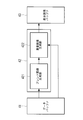
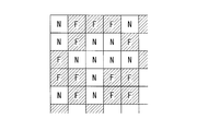
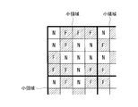
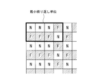
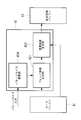
- FIG. 1 is an overall configuration diagram of an endoscope apparatus according to a first embodiment of the present invention. It is a block diagram of the image processing unit in the endoscope apparatus of FIG. It is a figure explaining the process of the normal light image and the fluorescence image in the image processing unit of FIG. It is a figure which shows a part of blend image produced
- an endoscope apparatus 1 according to a first embodiment of the present invention will be described with reference to FIGS. 1 to 5.
- an endoscope apparatus 1 according to the present embodiment can be inserted into a body, a light source unit 2 that outputs normal light and excitation light (special light), and is attached to a living tissue S in the body.
- An insertion unit 3 that irradiates normal light and excitation light to acquire an image signal of the living tissue S, a processor 4 that generates an image from the image signal acquired by the insertion unit 3, and an image generated by the processor 4
- a display unit 5 for displaying.
- the light source unit 2 includes a light source 21 that emits broadband light such as white light, a filter unit 22 that selectively transmits normal light and excitation light among the light emitted from the light source 21, and the filter unit 22 And a coupling lens 23 for converging normal light or excitation light transmitted through the light.
- the filter unit 22 includes a turret having a normal light filter that selectively transmits normal light that is broadband visible light, and an excitation light filter that selectively transmits narrow-band excitation light.
- the filter unit 22 rotates the turret according to the control by the timing control unit 44 described later, and alternately arranges the normal light filter and the excitation light filter on the output optical axis of the light source 21. Thereby, the normal light and the excitation light are alternately output from the light source unit 2.
- the insertion unit 3 is provided at the illumination unit 6 that irradiates the normal tissue and the excitation light output from the light source unit 2 toward the living tissue (subject) S from the distal end 3 a of the insertion unit 3 and the distal end 3 a of the insertion unit 3. And an imaging unit 7 for imaging the living tissue S.
- the illumination unit 6 includes a light guide fiber 61 disposed over almost the entire length of the insertion portion 3 in the longitudinal direction, and an illumination optical system 62 provided at the distal end 3a of the insertion portion 3.
- the light guide fiber 61 guides the light converged by the coupling lens 23 from the proximal end to the distal end.
- the illumination optical system 62 diffuses normal light and excitation light emitted from the distal end of the light guide fiber 61 and irradiates the living tissue S facing the distal end 3 a of the insertion portion 3.
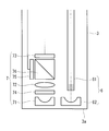
- the imaging unit 7 includes an objective lens 71 that collects light from the living tissue S, a converging lens 72 that converges the light collected by the objective lens 71, and an imaging element 73 that captures the light converged by the converging lens 72. It has. Reference numeral 74 denotes an excitation light cut filter that blocks excitation light and transmits light in other wavelength ranges.
- the image sensor 73 is, for example, a color CCD or a color CMOS. The image sensor 73 receives light incident from the objective lens 71, photoelectrically converts the received light to generate an image signal, and transmits the generated image signal to the processor 4.
- the processor 4 includes a data buffer 41 that temporarily holds an image signal received from the image sensor 73, an image processing unit 42 that processes the image signal received from the data buffer 41 and generates a superimposed image, and the image processing A display image buffer 43 that temporarily holds the superimposed image output from the unit 42, and a timing control unit 44 that synchronizes the operations of the buffers 41 and 43, the image processing unit 42, the filter unit 22, and the image sensor 73.
- Reference numeral 45 denotes an amplifier that amplifies the image signal output from the image sensor 73
- reference numeral 46 denotes a gain controller (AGC)
- reference numeral 47 converts an analog image signal to a digital signal.
- Reference numeral 48 denotes a DA converter that converts the digital image signal of the superimposed image output from the display image buffer 43 into an analog image signal.
- the timing control unit 44 causes the image sensor 73 to perform normal light exposure when a normal light filter is disposed on the output optical axis of the light source 21 and the normal tissue S is irradiated with the normal light, and the output of the light source 21 is output.
- the imaging element 73 executes the exposure of the fluorescence so that the normal light image signal and the fluorescence image signal are alternately displayed. 73.
- the data buffer 41 temporarily holds the normal light image signal and the fluorescence image signal received from the image sensor 73 and transmits the pair of normal light image signals and the fluorescence image signal to the image processing unit 42.
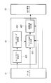
- the image processing unit 42 includes a blend image generation unit 421 and a superimposed image generation unit 422.
- FIG. 3 shows a process of generating a superimposed image from the normal light image and the fluorescence image by the image processing unit 42.
- a normal light image signal acquired by photographing broadband normal light includes three color image signals, that is, a red (R) image signal, a green (G) image signal, and a blue (B) image signal.
- the data buffer 41 transmits the G image signal and the fluorescence image signal to the blend image generation unit 421, and transmits the R image signal and the B image signal to the superimposed image generation unit 422.
- the blend image generation unit 421 generates a G component image from the G image signal received from the data buffer 41, and generates a fluorescence image from the fluorescence image signal.
- the G component image and the fluorescence image are composed of a large number of pixels arranged two-dimensionally in a matrix.
- the blend image generation unit 421 randomly selects some pixels from all the pixels of the G component image. However, the blend image generation unit 421 selects pixels substantially uniformly from the entire G component image so that the position of the selected pixel in the G component image does not bias. Next, the blend image generation unit 421 replaces each selected pixel with a pixel in the fluorescent image at the same position as the pixel. As a result, as shown in FIG. 4, a blend image is generated in which the pixels of the G component image and the pixels of the fluorescence image are mixed in a substantially uniform distribution over the entire blend image. In FIG. 4, “N” indicates a pixel of the normal light image, and “F” indicates a pixel of the fluorescent image. The blend image generation unit 421 transmits the generated blend image to the superimposed image generation unit 422.
- the superimposed image generation unit 422 uses the blend image received from the blend image generation unit 421 as a substitute for the G component image, and color-synthesizes the blend image with the R component image and the B component image received from the data buffer 41, whereby A color superimposed image is generated.
- the superimposed image generation unit 422 transmits the generated superimposed image to the display image buffer 43.
- the display image buffer 43 temporarily holds the superimposed image received from the superimposed image generation unit 422 and outputs the superimposed image to the display unit 5 via the DA converter 48 with a certain time interval.
- the endoscope apparatus 1 configured as described above.
- a fluorescent substance that accumulates in a lesioned part is administered to the living tissue S in advance.
- the insertion portion 3 is inserted into the body, the distal end 3a is disposed opposite to the living tissue S, and normal light and excitation light are alternately irradiated from the distal end 3a of the insertion portion 3 to the living tissue S by operation of the light source unit 2.
- normal light irradiated on the living tissue S normal light reflected on the surface of the living tissue S is collected by the objective lens 71.
- the normal light collected by the objective lens 71 is converged on the imaging surface of the image sensor 73 by the converging lens 72 and is acquired as a normal light image signal by the image sensor 73.
- the fluorescent substance contained in the lesion is excited by the excitation light to generate fluorescence, and the fluorescence and a part of the excitation light are collected by the objective lens 71. Only the fluorescence and excitation light collected by the objective lens 71 are extracted by the excitation light cut filter 74. The extracted fluorescence is converged on the imaging surface of the imaging element 73 by the converging lens 72 and acquired as a fluorescence image signal by the imaging element 73. The normal light image signal and the fluorescence image signal acquired alternately by the image sensor 73 as described above are transmitted to the processor 4.
- the normal light image signal and the fluorescence image signal are input to the data buffer 41 via the amplifier 45, the AGC 46 and the AD converter 47, and the pair of normal light image signal and the fluorescence image signal are processed from the data buffer 41. Input to the unit 42.
- the normal light image is separated into a G image signal, an R image signal, and a B image signal.
- the G image signal is input to the blend image generation unit 421 together with the fluorescent image signal, and the R image signal and the B image signal are input.
- the image signal is input to the superimposed image generation unit 422.
- the pixels of the G component image and the pixels of the fluorescence image are blended in a substantially uniform distribution by replacing some of the pixels in the G component image with the pixels of the fluorescence image.
- a blended image is generated.
- the blend image includes both the image of the living tissue S in the G component image and the fluorescence image in the fluorescence image.
- the generated blend image is color-combined with the R component image and the B component image in the superimposed image generation unit 422 to generate a superimposed image.
- the generated superimposed images are output from the display image buffer 43 to the display unit 5 via the DA converter 48 in order at predetermined time intervals. Thereby, the superimposed image is displayed on the display unit 5 as a live video.
- the blend image is an image in which the pixels of the G component image and the pixels of the fluorescence image are blended so as to be mixed in a substantially uniform distribution over the entire blend image.
- the fluorescent region having a sufficiently high gradation value but also the fluorescent region having a relatively low gradation value in the fluorescent region is synthesized with the blend image. Accordingly, there is an advantage that a superimposed image in which all of the fluorescent regions to be noticed by the observer are displayed can be generated.
- the gradation value of each pixel of the blend image is the gradation value of the pixel of the G color component image or the gradation value of the pixel of the fluorescent image itself.
- the blend image generation unit 421 divides the G component image into small regions including a predetermined number of pixels, and replaces the pixels that are replaced with the pixels of the fluorescence image.
- a predetermined number of small areas may be selected at random.
- the small area includes 4 pixels ⁇ 4 pixels, and eight “N” s are replaced with “F” in each small area.
- the blend image generation unit 421 may determine the pixel to be replaced with “F” for each small region, but instead, replace it with “F” from the array of pixels constituting the small region.
- a pattern may be determined by randomly selecting pixels to be applied, and the determined same pattern may be applied to all small regions. In this case, in the blend image, small regions having the same arrangement of “N” and “F” are repeated in the row direction and the column direction.
- the blend image generation unit (blend pattern setting unit) 421 does not randomly select a pixel to be replaced with a pixel of a fluorescent image among pixels of a G component image, but instead of a predetermined pixel. This is different from the first embodiment in that the selection is made according to the blend pattern.
- the blend image generation unit 421 stores a blend pattern that defines the arrangement of the pixel “N” of the G component image and the pixel “F” of the fluorescent image. As shown in FIG. 6, the blend pattern is a square lattice arrangement pattern in which “N” and “F” are alternately arranged in a checkered pattern in the row direction and the column direction in units of one pixel.
- the blend image generation unit 421 generates a blend image by replacing the pixels corresponding to “F” of the blend pattern among the pixels of the G component image with the pixels of the fluorescence image.
- Other configurations of the present embodiment are the same as those of the first embodiment.
- the pixels “N” of the G component image and the pixels “F” of the fluorescent image are arranged in a square lattice in units of one pixel, so that the noise included in the fluorescent image is effectively reduced in the blend image. Reduced. Thereby, there is an advantage that a superimposed image with less noise can be generated. Furthermore, in a superimposed image that is color-combined using a blend image in which the pixels “N” of the G component image are more uniformly distributed, there is an advantage that a color tone closer to that of the normal light image can be reproduced.
- a square lattice arrangement pattern in which “N” and “F” are arranged in a checkered pattern in units of one pixel has been described.
- “N” and “F” are a plurality of pixels arranged in a square pattern.
- a square lattice arrangement pattern arranged in a checkered pattern in units may be used. For example, “N” of 4 pixels having a square arrangement of 2 pixels ⁇ 2 pixels and “F” of 4 pixels having a square arrangement of 2 pixels ⁇ 2 pixels are alternately arranged in the row direction and the column direction. May be.
- the endoscope apparatus according to the present embodiment is common to the second embodiment in that the blend image generation unit 421 selects pixels to be replaced with the pixels of the fluorescence image according to a predetermined blend pattern. Is different from the second embodiment.
- the blend pattern has a cycle in which “N” and “F” are periodically arranged in the row direction and the column direction alternately in an arbitrary unit of one pixel or several pixels. It is an array pattern.
- the alternating period of “N” and “F” in the row direction and the alternating period of “N” and “F” in the column direction are different from each other.
- three “N” and one “F” are alternately arranged in the row direction, and one “N” and one “F” are alternately arranged in the column direction. Are arranged. Therefore, the alternating cycle, that is, the minimum repeating unit of “N” and “F” is four in the row direction and two in the column direction.
- the number of “F” is equal to or greater than the number of “N”.
- the number of “F” in the minimum repeating unit is less than the number of “N”, the effect of making the fluorescent region conspicuous in the superimposed image (described later) decreases.
- a periodic pattern corresponding to the “F” arrangement in the blend pattern is displayed in green on the superimposed image.
- the green pattern becomes clear in the fluorescent region where the blend image has a high gradation value. Therefore, the distinguishability of the fluorescent region in the superimposed image can be improved as compared with the case where the entire fluorescent region is displayed in a uniform green color.
- the green pattern is unclear to such an extent that it cannot be visually recognized.
- the blend pattern used in the blend image generation unit 421 may be changed continuously so that the pattern dynamically changes in the superimposed image.
- a frame counter 423 that counts the number of images input from the data buffer 41 to the blend image generation unit 421 is further provided.
- the blend image generation unit 421 stores a plurality of types of blend patterns, and the blend image generation unit 421 changes the blend pattern used for generation of the blend image according to the count number by the frame counter 423.
- the blend image generation unit 421 uses the first pattern when the count number is an even number, and uses a second pattern different from the first pattern when the count number is an odd number. Thereby, since the green pattern displayed on the fluorescent region of the superimposed image changes dynamically, the distinguishability of the fluorescent region can be further improved.
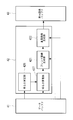
- the endoscope apparatus according to the present embodiment is different from the first embodiment in that it further includes a pattern size adjustment unit (blend pattern setting unit) 424.
- the blend image generation unit 421 selects pixels to be replaced with the pixels of the fluorescent image according to a predetermined blend pattern, as in the second embodiment.
- the blend image generation unit 421 stores a plurality of blend patterns of the same pattern having different pattern sizes.
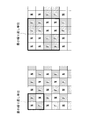
- the blend image generation unit 421 includes a plurality of blend patterns that are composed of a square lattice arrangement pattern of “N” and “F” and have different numbers of pixels in the minimum repeating unit. It is remembered. For example, in one blend pattern, as shown in the left diagram of FIG. 10, “N” and “F” are alternately arranged in the row direction and the column direction in units of one pixel, and the minimum repeating unit is four pixels. ing. In another blend pattern, as shown in the right diagram of FIG.
- N of 4 pixels having a square arrangement of 2 pixels ⁇ 2 pixels
- F of 4 pixels having a square arrangement of 2 pixels ⁇ 2 pixels
- the pattern size adjustment unit 424 allows an observer to input a pattern size using an input device (not shown).
- the pattern size corresponds to the number of pixels of the minimum repeating unit in the blend pattern.
- the pattern size can be designated as “2 ⁇ 2” or “4 ⁇ 4”.
- the blend image generation unit 421 selects a blend pattern having a pattern size designated to the pattern size adjustment unit 424, and generates a blend image using the selected blend pattern.
- Other configurations of the present embodiment are the same as those of the first embodiment.
- a checkered pattern corresponding to the array of “F” in the blend pattern is displayed in green.
- the pattern size is set so small that the checkerboard pattern cannot be visually recognized, that is, it appears to be uniform green, the fluorescent region can be naturally displayed in the superimposed image.
- a periodic array pattern as described in the third embodiment may be employed as the blend pattern instead of the square lattice array pattern.
- the present embodiment further includes a contrast measurement unit 425 that measures the contrast of the brightness of the fluorescent image, and the pattern size adjustment unit 424 has the contrast measured by the contrast measurement unit 425.
- the pattern size may be automatically determined based on the above.
- the contrast measuring unit 425 measures the contrast of the fluorescent image based on the width of the histogram of the gradation values of the fluorescent image.
- the gradation value of the fluorescent region in the fluorescent image is high, the brightness contrast between the fluorescent region and the non-fluorescent region increases, and the width of the histogram increases.
- the gradation value of the fluorescent region in the fluorescent image is low, the brightness contrast between the fluorescent region and the non-fluorescent region is low, and the width of the histogram is small.
- the pattern size adjustment unit 424 sets the pattern size larger as the contrast of the fluorescent image is lower.
- the distinguishability of the fluorescent region in the superimposed image is low.
- the fluorescent image is automatically changed to a large pattern size, and the distinguishability of the fluorescent region in the superimposed image is enhanced. In this way, by changing the pattern size based on the brightness contrast of the fluorescent image, the distinguishability of the fluorescent region in the superimposed image can be optimally automatically adjusted.
- the pattern size of the blend pattern is uniformly changed in the entire blend image, but instead, the pattern size may be determined for each region of the blend image. For example, a pattern size larger than the pattern size in the region where the gradation value is equal to or greater than the predetermined threshold may be applied to the region where the gradation value is less than the predetermined threshold in the fluorescent image.
- a brightness measurement unit (not shown) that measures the brightness of the fluorescent image
- the pattern size adjustment unit 424 is measured by the brightness measurement unit.
- the pattern size may be adjusted based on the brightness of the fluorescent image. For example, the brightness measurement unit calculates the average value of the gradation values of all the pixels of the fluorescent image as the brightness of the fluorescent image.
- the pattern size adjustment unit 424 sets a larger pattern size as the brightness of the fluorescent image measured by the brightness measurement unit is lower. By doing in this way, when the fluorescent image is dark, the pattern displayed on the superimposed image becomes larger, so that the distinguishability of the fluorescent region in the superimposed image can be improved.
- FIG. 12 illustrates a configuration in which a brightness measurement unit 426 and a brightness adjustment unit 427 are added to the image processing unit 42 in the first embodiment.
- the brightness adjustment unit 427 calculates the gradation values of all the pixels of the fluorescence image based on the brightness of the fluorescence image so that the brightness of the fluorescence image is equal to the brightness of the G component image.
- the brightness of the fluorescent image is increased by adding the obtained values.
- the blend image generation unit 421 generates a blend image using the fluorescent image whose brightness is adjusted by the brightness adjustment unit 427.
- the color tone of the superimposed image is changed to the color tone of the normal light image. You can get closer.
- the normal light and the excitation light are alternately irradiated onto the living tissue S, and the normal light image signal and the fluorescence image signal are generated using the single image sensor 73.
- normal light and excitation light may be simultaneously irradiated onto the living tissue S, and the normal light image signal and the fluorescence image signal may be simultaneously acquired.
- the imaging unit 7 divides the light collected by the other imaging device 75 and the objective lens 71 into two, and the imaging device (normal light image acquisition unit). 73 and a beam splitter 76 that distributes to the image sensor (special light image acquisition unit) 75.
- the fluorescent image is blended with the G component image so that the fluorescent region is displayed in green in the superimposed image. It may be an R component image or a B component image.
- the excitation light and the fluorescence image for exciting the fluorescent material have been described as examples of the special light and the special light image.
- the types of the special light and the special light image are the same. It is not limited to.
- an infrared light image may be acquired using infrared light
- an NBI image may be acquired using blue narrowband light and green narrowband light.
Landscapes
- Life Sciences & Earth Sciences (AREA)
- Health & Medical Sciences (AREA)
- Engineering & Computer Science (AREA)
- Surgery (AREA)
- Physics & Mathematics (AREA)
- Biomedical Technology (AREA)
- Public Health (AREA)
- Veterinary Medicine (AREA)
- Biophysics (AREA)
- Pathology (AREA)
- General Health & Medical Sciences (AREA)
- Animal Behavior & Ethology (AREA)
- Molecular Biology (AREA)
- Heart & Thoracic Surgery (AREA)
- Medical Informatics (AREA)
- Radiology & Medical Imaging (AREA)
- Optics & Photonics (AREA)
- Nuclear Medicine, Radiotherapy & Molecular Imaging (AREA)
- Signal Processing (AREA)
- Multimedia (AREA)
- General Physics & Mathematics (AREA)
- Theoretical Computer Science (AREA)
- Endoscopes (AREA)
- Instruments For Viewing The Inside Of Hollow Bodies (AREA)
Abstract
Description
本発明は、広帯域の可視光が照射された被写体を撮影して通常光画像を取得する通常光画像取得部と、狭帯域の特殊光が照射された前記被写体を撮影して特殊光画像を取得する特殊光画像取得部と、前記通常光画像を構成する複数の色成分画像の内の一の色成分画像と前記特殊光画像とを合成してブレンド画像を生成するブレンド画像生成部と、該ブレンド画像生成部によって生成された前記ブレンド画像と、前記複数の色成分画像の内の他の色成分画像とを合成することによって、カラーの重畳画像を生成する重畳画像生成部とを備え、前記ブレンド画像生成部は、前記一の色成分画像の画素の内の一部の画素を選択し、選択された一部の画素を前記特殊光画像の対応する画素に置換することによって前記ブレンド画像を生成するとともに、前記ブレンド画像の全体にわたって前記一の色成分画像の画素および前記特殊光画像の画素の分布が略均一となるように、前記一の色成分画像の一部の画素を前記特殊光画像の画素に置換する内視鏡装置を提供する。
このようにすることで、色調の維持効果およびノイズの低減効果を安定的に得ることができる。
このようにすることで、重畳画像の内、特殊光画像において高い階調値を有する注目領域には、周期配列パターンに相当する模様が、特殊光画像と合成された一の色成分画像の色で表示される。この模様によって注目領域の識別性を向上することができる。
このようにすることで、色調の変化およびノイズがさらに低減された重畳画像を得ることができる。
このようにすることで、ブレンド画像の生成に使用するブレンドパターンをブレンドパターン設定部によって変更することができる。
注目領域の階調値が低く特殊光画像の明るさのコントラストが低い場合、重畳画像において注目領域の識別性が低くなる。そこで、ブレンドパターンの最小繰り返し単位を構成する画素数を増大し、ブレンド画像における注目領域の模様を大きくすることによって、階調値が低い注目領域の識別性を向上することができる。
特殊光画像が暗い場合、重畳画像において注目領域の識別性が低くなる。そこで、ブレンドパターンの最小繰り返し単位を構成する画素数を増大し、ブレンド画像における注目領域の模様を大きくすることによって、階調値が低い注目領域の識別性を向上することができる。
特殊光画像の明るさと一の色成分画像の明るさとの差異が大きい場合、通常光画像の色調と重畳画像の色調との差異が大きくなる。そこで、特殊光画像の明るさを調整することによって、通常光画像の色調により近い色調を有する重畳画像を生成することができる。
本発明の第1の実施形態に係る内視鏡装置1について図1から図5を参照して説明する。
本実施形態に係る内視鏡装置1は、図1に示されるように、通常光および励起光(特殊光)を出力する光源ユニット2と、体内に挿入可能であり、体内の生体組織Sに通常光および励起光を照射して生体組織Sの画像信号を取得する挿入部3と、該挿入部3によって取得された画像信号から画像を生成するプロセッサ4と、該プロセッサ4によって生成された画像を表示する表示部5とを備えてる。
撮像素子73は、例えば、カラーCCDまたはカラーCMOSである。撮像素子73は、対物レンズ71から入射した光を受光し、受光した光を光電変換して画像信号を生成し、生成された画像信号をプロセッサ4へ送信する。
画像処理ユニット42は、図2に示されるように、ブレンド画像生成部421と、重畳画像生成部422とを備えている。図3は、画像処理ユニット42による、通常光画像および蛍光画像からの重畳画像の生成過程を示している。広帯域の通常光を撮影して取得された通常光画像信号は、3色の画像信号、すなわち赤(R)画像信号、緑(G)画像信号および青(B)画像信号から構成されている。データバッファ41は、G画像信号および蛍光画像信号をブレンド画像生成部421に送信し、R画像信号およびB画像信号を重畳画像生成部422に送信する。
表示画像バッファ43は、重畳画像生成部422から受信した重畳画像を一時的に保持し、重畳画像を一定の時間間隔を空けてDA変換器48を介して表示部5へ出力する。
本実施形態に係る内視鏡装置1を用いて生体組織Sを観察するには、予め、例えば病変部に集積する蛍光物質を生体組織Sに投与しておく。
まず、体内に挿入部3を挿入して先端3aを生体組織Sに対向配置し、光源ユニット2の作動によって通常光および励起光を交互に挿入部3の先端3aから生体組織Sに照射する。
生体組織Sに通常光が照射されると、生体組織Sの表面において反射された通常光が対物レンズ71によって集められる。対物レンズ71によって集められた通常光は、収束レンズ72によって撮像素子73の撮像面に収束され、該撮像素子73によって通常光画像信号として取得される。
次に、本発明の第2の実施形態に係る内視鏡装置について図6を参照して説明する。
本実施形態に係る内視鏡装置は、ブレンド画像生成部(ブレンドパターン設定部)421が、G成分画像の画素の内、蛍光画像の画素に置換する画素をランダムに選択するのではなく、所定のブレンドパターンに従って選択する点で、第1の実施形態と異なる。
本実施形態のその他の構成は、第1の実施形態と同様である。
次に、本発明の第3の実施形態に係る内視鏡装置について図7および図8を参照して説明する。
本実施形態に係る内視鏡装置は、ブレンド画像生成部421が、蛍光画像の画素に置換する画素を所定のブレンドパターンに従って選択する点で第2の実施形態と共通しているが、ブレンドパターンが第2の実施形態とは異なる。
具体的には、図8に示されるように、データバッファ41からブレンド画像生成部421に入力される画像の数をカウントするフレームカウンタ423がさらに設けられる。ブレンド画像生成部421には複数種類のブレンドパターンが記憶されており、ブレンド画像生成部421は、フレームカウンタ423によるカウント数に従って、ブレンド画像の生成に使用するブレンドパターンを変更するようになっている。例えば、ブレンド画像生成部421は、カウント数が偶数のときには第1のパターンを使用し、カウント数が奇数のときには第1のパターンとは異なる第2のパターンを使用する。これにより、重畳画像の蛍光領域に表示される緑色の模様が動的に変化するので、蛍光領域の識別性をさらに向上することができる。
次に、本発明の第4の実施形態に係る内視鏡装置について図9から図11を参照して説明する。
本実施形態に係る内視鏡装置は、図9に示されるように、パターンサイズ調整部(ブレンドパターン設定部)424をさらに備える点で、第1の実施形態と異なっている。
本実施形態においても、ブレンド画像生成部421は、第2の実施形態と同様に、蛍光画像の画素に置換する画素を所定のブレンドパターンに従って選択する。ただし、本実施形態において、ブレンド画像生成部421には、パターンサイズの異なる同一パターンの複数のブレンドパターンが記憶されている。
ブレンド画像生成部421は、パターンサイズ調整部424に対して指定されたパターンサイズのブレンドパターンを選択し、選択したブレンドパターンを使用してブレンド画像を生成する。
本実施形態のその他の構成は、第1の実施形態と同様である。
なお、本実施形態においては、ブレンドパターンとして、正方格子配列パターンではなく、第3の実施形態で説明したような周期配列パターンを採用してもよい。
パターンサイズ調整部424は、蛍光画像のコントラストが低い程、パターンサイズを大きく設定する。
例えば、蛍光画像の内、階調値が所定の閾値未満である領域には、階調値が所定の閾値以上である領域におけるパターンサイズよりも大きなパターンサイズを適用してもよい。このようにすることで、重畳画像において、暗く識別性の低い蛍光領域に対しては大きな模様を表示させて識別性を向上することができる。
明るさ測定部は、例えば、蛍光画像の全画素の階調値の平均値を蛍光画像の明るさとして算出する。パターンサイズ調整部424は、明るさ測定部によって測定された蛍光画像の明るさが低い程、大きなパターンサイズに設定する。このようにすることで、蛍光画像が暗い場合には重畳画像に表示される模様が大きくなることによって、重畳画像における蛍光領域の識別性を向上することができる。
次に、本発明の第5の実施形態に係る内視鏡装置について図12を参照して説明する。
本実施形態に係る内視鏡装置は、上述した第1から第4の実施形態を変形したものであり、図12に示されるように、蛍光画像の明るさを測定する明るさ測定部426と、明るさ測定部426によって測定された蛍光画像の明るさに基づいて、当該蛍光画像の明るさを調整する明るさ調整部427とをさらに備える。図12には、第1の実施形態における画像処理ユニット42に明るさ測定部426および明るさ調整部427を追加した構成を例示している。
本実施形態において、ブレンド画像生成部421は、明るさ調整部427によって明るさが調整された蛍光画像を使用してブレンド画像を生成する。
2 光源ユニット
421 ブレンド画像生成部(ブレンドパターン設定部)
422 重畳画像生成部
424 パターンサイズ調整部(ブレンドパターン設定部)
425 コントラスト測定部
426 明るさ測定部
427 明るさ調整部
73 撮像素子(通常光画像取得部、特殊光画像取得部)
Claims (8)
- 広帯域の可視光が照射された被写体を撮影して通常光画像を取得する通常光画像取得部と、
狭帯域の特殊光が照射された前記被写体を撮影して特殊光画像を取得する特殊光画像取得部と、
前記通常光画像を構成する複数の色成分画像の内の一の色成分画像と前記特殊光画像とを合成してブレンド画像を生成するブレンド画像生成部と、
該ブレンド画像生成部によって生成された前記ブレンド画像と、前記複数の色成分画像の内の他の色成分画像とを合成することによって、カラーの重畳画像を生成する重畳画像生成部とを備え、
前記ブレンド画像生成部は、前記一の色成分画像の画素の内の一部の画素を選択し、選択された一部の画素を前記特殊光画像の対応する画素に置換することによって前記ブレンド画像を生成するとともに、前記ブレンド画像の全体にわたって前記一の色成分画像の画素および前記特殊光画像の画素の分布が略均一となるように、前記一の色成分画像の一部の画素を前記特殊光画像の画素に置換する内視鏡装置。 - 前記ブレンド画像生成部は、前記一の色成分画像の画素および前記特殊光画像の画素が1画素単位または複数の画素単位からなる最小繰り返し単位で行方向および列方向に交互に配列されるように前記一の色成分画像の画素および前記特殊光画像の画素の配列を規定したブレンドパターンを有し、該ブレンドパターンにおける前記特殊光画像の画素の配列に従って前記一の色成分画像から選択した前記一部の画素を前記特殊光画像の画素に置換する請求項1に記載の内視鏡装置。
- 前記ブレンドパターンは、前記行方向における前記最小繰り返し単位と前記列方向における前記最小繰り返し単位とが互いに異なる周期配列パターンである請求項2に記載の内視鏡装置。
- 前記ブレンドパターンは、前記行方向における前記最小繰り返し単位と前記列方向における前記最小繰り返し単位とが互いに等しい正方格子配列パターンである請求項2に記載の内視鏡装置。
- 前記ブレンドパターンを設定するブレンドパターン設定部を備え、
前記ブレンド画像生成部が、前記ブレンドパターン設定部によって設定されたブレンドパターンに従って前記ブレンド画像を生成する請求項2から請求項4のいずれかに記載の内視鏡装置。 - 前記特殊光画像の明るさのコントラストを測定するコントラスト測定部を備え、
前記ブレンドパターン設定部が、前記コントラスト測定部によって測定されたコントラストに基づいて、該コントラストが低い程、前記ブレンドパターンにおける前記最小繰り返し単位を構成する画素数が多くなるように、前記ブレンドパターンを設定する請求項5に記載の内視鏡装置。 - 前記特殊光画像の明るさを測定する明るさ測定部を備え、
前記ブレンドパターン設定部が、前記明るさ測定部によって測定された明るさに基づいて、該明るさが低い程、前記ブレンドパターンにおける前記最小繰り返し単位を構成する画素数が多くなるように、前記ブレンドパターンを設定する請求項5に記載の内視鏡装置。 - 前記特殊光画像の明るさを測定する明るさ測定部と、
該明るさ測定部によって測定された明るさに基づいて前記特殊光画像の明るさを調整する明るさ調整部とを備え、
前記ブレンド画像生成部が、前記明るさ調整部によって明るさが調整された特殊光画像を用いて前記ブレンド画像を生成する請求項1から請求項6のいずれかに記載の内視鏡装置。
Priority Applications (5)
| Application Number | Priority Date | Filing Date | Title |
|---|---|---|---|
| PCT/JP2015/058169 WO2016147366A1 (ja) | 2015-03-19 | 2015-03-19 | 内視鏡装置 |
| CN201580077817.1A CN107427183B (zh) | 2015-03-19 | 2015-03-19 | 内窥镜装置 |
| JP2017505963A JP6396577B2 (ja) | 2015-03-19 | 2015-03-19 | 内視鏡装置 |
| DE112015006176.2T DE112015006176T5 (de) | 2015-03-19 | 2015-03-19 | Endoskopvorrichtung |
| US15/701,653 US10750929B2 (en) | 2015-03-19 | 2017-09-12 | Endoscope device for generating color superimposed image |
Applications Claiming Priority (1)
| Application Number | Priority Date | Filing Date | Title |
|---|---|---|---|
| PCT/JP2015/058169 WO2016147366A1 (ja) | 2015-03-19 | 2015-03-19 | 内視鏡装置 |
Related Child Applications (1)
| Application Number | Title | Priority Date | Filing Date |
|---|---|---|---|
| US15/701,653 Continuation US10750929B2 (en) | 2015-03-19 | 2017-09-12 | Endoscope device for generating color superimposed image |
Publications (1)
| Publication Number | Publication Date |
|---|---|
| WO2016147366A1 true WO2016147366A1 (ja) | 2016-09-22 |
Family
ID=56919963
Family Applications (1)
| Application Number | Title | Priority Date | Filing Date |
|---|---|---|---|
| PCT/JP2015/058169 Ceased WO2016147366A1 (ja) | 2015-03-19 | 2015-03-19 | 内視鏡装置 |
Country Status (5)
| Country | Link |
|---|---|
| US (1) | US10750929B2 (ja) |
| JP (1) | JP6396577B2 (ja) |
| CN (1) | CN107427183B (ja) |
| DE (1) | DE112015006176T5 (ja) |
| WO (1) | WO2016147366A1 (ja) |
Cited By (3)
| Publication number | Priority date | Publication date | Assignee | Title |
|---|---|---|---|---|
| WO2018100732A1 (ja) * | 2016-12-02 | 2018-06-07 | オリンパス株式会社 | 内視鏡用画像処理装置 |
| US20190289179A1 (en) * | 2017-01-13 | 2019-09-19 | Olympus Corporation | Endoscope image processing device and endoscope image processing method |
| JPWO2021039870A1 (ja) * | 2019-08-27 | 2021-03-04 |
Families Citing this family (2)
| Publication number | Priority date | Publication date | Assignee | Title |
|---|---|---|---|---|
| WO2018047369A1 (ja) * | 2016-09-06 | 2018-03-15 | オリンパス株式会社 | 内視鏡システム |
| JPWO2020035929A1 (ja) * | 2018-08-16 | 2021-08-10 | オリンパス株式会社 | 内視鏡装置、内視鏡装置の作動方法及び画像処理プログラム |
Citations (4)
| Publication number | Priority date | Publication date | Assignee | Title |
|---|---|---|---|---|
| JPH04341232A (ja) * | 1991-03-11 | 1992-11-27 | Olympus Optical Co Ltd | 電子内視鏡システム |
| JP2011101771A (ja) * | 2009-11-12 | 2011-05-26 | Fujifilm Corp | 画像表示装置 |
| JP2011194164A (ja) * | 2010-03-23 | 2011-10-06 | Olympus Corp | 蛍光観察装置 |
| JP2012010962A (ja) * | 2010-06-30 | 2012-01-19 | Fujifilm Corp | 励起光の光源装置および電子内視鏡システム |
Family Cites Families (34)
| Publication number | Priority date | Publication date | Assignee | Title |
|---|---|---|---|---|
| US6346940B1 (en) | 1997-02-27 | 2002-02-12 | Kabushiki Kaisha Toshiba | Virtualized endoscope system |
| JPH10234664A (ja) | 1997-02-27 | 1998-09-08 | Toshiba Corp | 画像処理装置 |
| KR100411631B1 (ko) * | 2001-10-18 | 2003-12-18 | 주식회사 메디미르 | 형광 내시경 장치 및 그 장치를 이용한 진단부위 조상 방법 |
| JP3950715B2 (ja) * | 2002-03-05 | 2007-08-01 | 富士フイルム株式会社 | 固体撮像素子およびこれを用いた撮像装置 |
| JP4394356B2 (ja) | 2003-02-07 | 2010-01-06 | Hoya株式会社 | 電子内視鏡装置 |
| JP2004321244A (ja) | 2003-04-21 | 2004-11-18 | Olympus Corp | 電子内視鏡システム |
| JP2006263044A (ja) * | 2005-03-23 | 2006-10-05 | Fuji Photo Film Co Ltd | 蛍光検出システム |
| JP4761899B2 (ja) | 2005-09-12 | 2011-08-31 | Hoya株式会社 | 電子内視鏡システム |
| JP4799109B2 (ja) | 2005-09-29 | 2011-10-26 | 富士フイルム株式会社 | 電子内視鏡装置 |
| JP4752550B2 (ja) * | 2006-03-14 | 2011-08-17 | ソニー株式会社 | カラー撮像素子の製造方法およびその装置 |
| US7773127B2 (en) * | 2006-10-13 | 2010-08-10 | Apple Inc. | System and method for RAW image processing |
| US8237808B2 (en) * | 2007-01-17 | 2012-08-07 | Sony Corporation | Solid state imaging device and imaging apparatus adjusting the spatial positions of pixels after addition by controlling the ratio of weight values during addition |
| US8446470B2 (en) * | 2007-10-04 | 2013-05-21 | Magna Electronics, Inc. | Combined RGB and IR imaging sensor |
| JP5361488B2 (ja) * | 2009-03-24 | 2013-12-04 | オリンパス株式会社 | 蛍光観察装置 |
| JP5572326B2 (ja) * | 2009-03-26 | 2014-08-13 | オリンパス株式会社 | 画像処理装置、撮像装置、画像処理プログラムおよび画像処理方法 |
| CN102781305B (zh) | 2010-03-09 | 2015-06-03 | 奥林巴斯株式会社 | 荧光内窥镜装置 |
| JP5597021B2 (ja) * | 2010-04-15 | 2014-10-01 | オリンパス株式会社 | 画像処理装置及びプログラム |
| JP2012004787A (ja) * | 2010-06-16 | 2012-01-05 | Sony Corp | 画像処理装置、および画像処理方法、並びにプログラム |
| JP5442571B2 (ja) * | 2010-09-27 | 2014-03-12 | パナソニック株式会社 | 固体撮像装置及び撮像装置 |
| JP5259882B2 (ja) * | 2010-09-30 | 2013-08-07 | オリンパスメディカルシステムズ株式会社 | 撮像装置 |
| CN103458759B (zh) | 2011-03-31 | 2015-10-14 | 奥林巴斯株式会社 | 荧光观察装置 |
| WO2013024788A1 (ja) | 2011-08-15 | 2013-02-21 | オリンパスメディカルシステムズ株式会社 | 撮像装置 |
| JP6017219B2 (ja) * | 2012-08-01 | 2016-10-26 | オリンパス株式会社 | 蛍光観察装置および蛍光観察システム |
| JP5789280B2 (ja) | 2013-05-14 | 2015-10-07 | 富士フイルム株式会社 | プロセッサ装置、内視鏡システム、及び内視鏡システムの作動方法 |
| US10165972B2 (en) * | 2013-07-12 | 2019-01-01 | Inthesmart Co., Ltd. | Apparatus and method for detecting NIR fluorescence at sentinel lymph node |
| KR101514204B1 (ko) * | 2013-07-12 | 2015-04-23 | 한국전기연구원 | 감시림프절의 근적외선 형광 검출 장치 및 방법 |
| JP6533358B2 (ja) | 2013-08-06 | 2019-06-19 | 三菱電機エンジニアリング株式会社 | 撮像装置 |
| KR20150033162A (ko) * | 2013-09-23 | 2015-04-01 | 삼성전자주식회사 | 컴포지터, 이를 포함하는 시스템온칩 및 이의 구동 방법 |
| JP5932748B2 (ja) * | 2013-09-27 | 2016-06-08 | 富士フイルム株式会社 | 内視鏡システム |
| JP6237415B2 (ja) | 2014-03-31 | 2017-11-29 | 株式会社Jvcケンウッド | 映像表示装置 |
| JP6197771B2 (ja) * | 2014-09-25 | 2017-09-20 | 株式会社Jvcケンウッド | 画像接合装置、撮像装置、画像接合方法、及び画像接合プログラム |
| CN106163373B (zh) | 2014-10-15 | 2018-05-01 | 奥林巴斯株式会社 | 信号处理装置和内窥镜系统 |
| US9635325B2 (en) * | 2015-05-29 | 2017-04-25 | Semiconductor Components Industries, Llc | Systems and methods for detecting ultraviolet light using image sensors |
| US10708478B2 (en) * | 2016-03-23 | 2020-07-07 | Karl Storz Imaging, Inc. | Image transformation and display for fluorescent and visible imaging |
-
2015
- 2015-03-19 CN CN201580077817.1A patent/CN107427183B/zh active Active
- 2015-03-19 JP JP2017505963A patent/JP6396577B2/ja active Active
- 2015-03-19 DE DE112015006176.2T patent/DE112015006176T5/de not_active Withdrawn
- 2015-03-19 WO PCT/JP2015/058169 patent/WO2016147366A1/ja not_active Ceased
-
2017
- 2017-09-12 US US15/701,653 patent/US10750929B2/en active Active
Patent Citations (4)
| Publication number | Priority date | Publication date | Assignee | Title |
|---|---|---|---|---|
| JPH04341232A (ja) * | 1991-03-11 | 1992-11-27 | Olympus Optical Co Ltd | 電子内視鏡システム |
| JP2011101771A (ja) * | 2009-11-12 | 2011-05-26 | Fujifilm Corp | 画像表示装置 |
| JP2011194164A (ja) * | 2010-03-23 | 2011-10-06 | Olympus Corp | 蛍光観察装置 |
| JP2012010962A (ja) * | 2010-06-30 | 2012-01-19 | Fujifilm Corp | 励起光の光源装置および電子内視鏡システム |
Cited By (8)
| Publication number | Priority date | Publication date | Assignee | Title |
|---|---|---|---|---|
| WO2018100732A1 (ja) * | 2016-12-02 | 2018-06-07 | オリンパス株式会社 | 内視鏡用画像処理装置 |
| CN110022751A (zh) * | 2016-12-02 | 2019-07-16 | 奥林巴斯株式会社 | 内窥镜用图像处理装置 |
| JPWO2018100732A1 (ja) * | 2016-12-02 | 2019-10-17 | オリンパス株式会社 | 内視鏡用画像処理装置 |
| US10729310B2 (en) | 2016-12-02 | 2020-08-04 | Olympus Corporation | Endoscope image processing devices |
| CN110022751B (zh) * | 2016-12-02 | 2021-11-30 | 奥林巴斯株式会社 | 内窥镜用图像处理装置 |
| US20190289179A1 (en) * | 2017-01-13 | 2019-09-19 | Olympus Corporation | Endoscope image processing device and endoscope image processing method |
| JPWO2021039870A1 (ja) * | 2019-08-27 | 2021-03-04 | ||
| WO2021039870A1 (ja) * | 2019-08-27 | 2021-03-04 | ソニー・オリンパスメディカルソリューションズ株式会社 | 医療用画像処理装置および医療用観察システム |
Also Published As
| Publication number | Publication date |
|---|---|
| CN107427183A (zh) | 2017-12-01 |
| JP6396577B2 (ja) | 2018-09-26 |
| JPWO2016147366A1 (ja) | 2017-12-28 |
| DE112015006176T5 (de) | 2017-10-26 |
| US20180000317A1 (en) | 2018-01-04 |
| US10750929B2 (en) | 2020-08-25 |
| CN107427183B (zh) | 2019-04-19 |
Similar Documents
| Publication | Publication Date | Title |
|---|---|---|
| JP5698878B2 (ja) | 内視鏡装置 | |
| JP6461797B2 (ja) | 蛍光観察装置 | |
| JP6396577B2 (ja) | 内視鏡装置 | |
| JP5670264B2 (ja) | 内視鏡システム、及び内視鏡システムの作動方法 | |
| JP5863709B2 (ja) | 内視鏡システム | |
| JP6739542B2 (ja) | 内視鏡用画像処理装置および内視鏡用画像処理方法 | |
| JP5200200B2 (ja) | 医療機器 | |
| JPWO2019087557A1 (ja) | 内視鏡システム | |
| JP2008043604A (ja) | 内視鏡装置 | |
| JPWO2019230095A1 (ja) | カメラ装置、画像処理方法およびカメラシステム | |
| JP7702294B2 (ja) | 内視鏡システム及びその作動方法 | |
| JPWO2015115151A1 (ja) | 蛍光観察装置 | |
| JP7374600B2 (ja) | 医療用画像処理装置及び医療用観察システム | |
| WO2018047369A1 (ja) | 内視鏡システム | |
| CN103874451A (zh) | 内窥镜系统以及图像生成方法 | |
| JP5041936B2 (ja) | 生体観測装置 | |
| JP6137892B2 (ja) | 撮像システム | |
| JP2011250925A (ja) | 電子内視鏡システム | |
| JP7551465B2 (ja) | 医療用画像処理装置及び医療用観察システム | |
| JP4694310B2 (ja) | 電子内視鏡、内視鏡光源装置、内視鏡プロセッサ、および内視鏡システム | |
| WO2017149742A1 (ja) | 内視鏡用画像処理装置 | |
| JP6205531B1 (ja) | 内視鏡システム | |
| JP2018192043A (ja) | 内視鏡及び内視鏡システム | |
| JP5331863B2 (ja) | 内視鏡装置 | |
| WO2017085850A1 (ja) | 内視鏡用画像処理装置 |
Legal Events
| Date | Code | Title | Description |
|---|---|---|---|
| 121 | Ep: the epo has been informed by wipo that ep was designated in this application |
Ref document number: 15885462 Country of ref document: EP Kind code of ref document: A1 |
|
| ENP | Entry into the national phase |
Ref document number: 2017505963 Country of ref document: JP Kind code of ref document: A |
|
| WWE | Wipo information: entry into national phase |
Ref document number: 112015006176 Country of ref document: DE |
|
| 122 | Ep: pct application non-entry in european phase |
Ref document number: 15885462 Country of ref document: EP Kind code of ref document: A1 |