WO2017149742A1 - 内視鏡用画像処理装置 - Google Patents
内視鏡用画像処理装置 Download PDFInfo
- Publication number
- WO2017149742A1 WO2017149742A1 PCT/JP2016/056712 JP2016056712W WO2017149742A1 WO 2017149742 A1 WO2017149742 A1 WO 2017149742A1 JP 2016056712 W JP2016056712 W JP 2016056712W WO 2017149742 A1 WO2017149742 A1 WO 2017149742A1
- Authority
- WO
- WIPO (PCT)
- Prior art keywords
- image
- unit
- superimposed
- region
- interest
- Prior art date
Links
Images


Classifications
-
- A—HUMAN NECESSITIES
- A61—MEDICAL OR VETERINARY SCIENCE; HYGIENE
- A61B—DIAGNOSIS; SURGERY; IDENTIFICATION
- A61B1/00—Instruments for performing medical examinations of the interior of cavities or tubes of the body by visual or photographical inspection, e.g. endoscopes; Illuminating arrangements therefor
- A61B1/04—Instruments for performing medical examinations of the interior of cavities or tubes of the body by visual or photographical inspection, e.g. endoscopes; Illuminating arrangements therefor combined with photographic or television appliances
Definitions
- the present invention relates to an endoscope image processing apparatus.
- an endoscope apparatus that acquires a normal light image such as a white light image and a special light image such as a fluorescence image and displays the normal light image and the special light image in a superimposed manner is known (for example, (See Patent Documents 1 and 2.)
- a normal light image and a special light image As a method of superimposing a normal light image and a special light image, in Patent Document 1, a special light image is added to one of the three color component images of R, G, and B constituting the normal light image.
- Patent Document 2 a region of interest having a high gradation value is extracted from the special light image, and the extracted region of interest is added to the normal light image.
- the gradation value of the fluorescent image is added to the gradation value of the one color component image, and the gradation value of the one color component image is raised.
- the color tone of the superimposed image is entirely biased to the color of the component image on which the special light image is superimposed, and the color tone of the superimposed image is different from the color tone of the normal light image.
- the fluorescent image often has a low SN ratio, and there is a problem that the noise of the fluorescent image is directly reflected in the superimposed image.
- a region of interest that has a relatively low tone value that does not satisfy the extraction criterion is a region that should be noticed by the observer, although it is a region that should be noticed. There is a possibility that the image is not extracted and is not displayed on the superimposed image.
- the present invention has been made in view of the above-described circumstances, and is for an endoscope that can generate a superimposed image in which a change in color tone and noise are small and a region of interest in a special light image is displayed.
- An object is to provide an image processing apparatus.
- the present invention provides the following means.
- the present invention provides a normal light image generating unit that generates a normal light image of a subject irradiated with broadband visible light, and the subject irradiated with a narrow band of special light that specifically acts on a region of interest in the subject.
- a special light image generating unit that generates the special light image, and any one of a plurality of color component images constituting the normal light image is combined with the special light image to generate a blend image.
- the blended image and the other color component images of the plurality of color component images are combined to generate a color superimposed image; and the superimposed image generated by the superimposed image generating unit
- a partial combining unit that generates a partial combined image by combining at least a portion of the normal light image with a part; an image output unit that outputs one of the superimposed image and the partial combined image to a display device; and the region of interest Before The output from the image output unit is based on either the ratio of the region of interest in the entire superimposed image and the background ratio of the background area of the subject excluding the region of interest in the entire superimposed image.
- a display switching unit that switches between the composite image, and the superimposed image generation unit selects a part of the pixels of the color component image, and selects the selected part of the pixels.
- the blend image is generated by substituting the corresponding pixels of the special light image, and the distribution of the pixels of the one color component image and the pixels of the special light image is substantially uniform throughout the blend image.
- the normal light image of the color generated by the normal light image generation unit is separated into one color component image and another color component image, and the one color component image is separated by the special light image generation unit.
- a blended image is generated by combining with the generated special light image.
- the generated blend image is color-synthesized with other color component images by the superimposed image generation unit. Thereby, a superimposed image in which the special light image is superimposed on the normal light image is obtained.
- the special light image is synthesized almost uniformly into the blend image without being subjected to processing for extracting only a part of the region. Therefore, the region of interest in the special light image can be displayed on the superimposed image. Furthermore, by blending the pixels of one color component image and the pixels of the special light image as they are in the blend image, the change in the gradation value of the blend image with respect to the one color component image is reduced, and the special light image The included noise is reduced in the blend image. Thereby, it is possible to generate a superimposed image with less change in color tone and less noise than the normal light image.
- the image displayed on the display device is a combination of the superimposed image and the partial composite image according to the ratio of the region of interest occupied by the region of interest in the entire superimposed image or the background ratio of the background region of the subject excluding the region of interest in the entire superimposed image.
- the display switching unit switches between them.
- the region of interest exists only in a part of the superimposed image
- the observer can easily recognize the region of interest in the superimposed image based on the color contrast between the region of interest and the background region surrounding the region of interest. can do.
- most of the superimposed image is the region of interest, it is difficult for the observer to determine whether or not the imaging range of the superimposed image is the region of interest.
- the partial composite image is displayed so that the observer can view the current observation range based on the normal light image in the partial composite image. It can be easily recognized whether or not.
- a ratio calculation unit that calculates the background ratio is provided, and the display switching unit displays the superimposed image when the background ratio calculated by the ratio calculation unit is larger than a predetermined threshold.
- the partial composite image may be output from the image output unit when the background ratio is equal to or less than a predetermined threshold.
- a ratio calculation unit that calculates the region-of-interest ratio is provided, and the display switching unit displays the superimposed image when the region-of-interest ratio calculated by the ratio calculation unit is less than a predetermined threshold.
- the partial output image may be output from the image output unit and output from the image output unit when the region-of-interest ratio is equal to or greater than the threshold value. The larger the region-of-interest ratio, the smaller the background ratio.
- the region-of-interest ratio is a predetermined value or more, that is, whether it is a condition that makes it difficult for the observer to determine the region of interest.
- the image suitable for observation can be displayed.
- the ratio calculation unit may calculate a ratio of pixels having a predetermined hue among all pixels of the superimposed image as the background ratio. Since the hue of the region of interest in the superimposed image is biased to the color of the blended image, the background region can be specified based on the hue of each pixel of the superimposed image, and the background ratio can be accurately calculated.
- an observation distance input unit for inputting an observation distance to the subject is provided, and the display switching unit performs the superimposition when the observation distance input to the observation distance input unit is larger than a predetermined threshold.
- An image may be output from the image output unit, and the partial composite image may be output from the image output unit when the observation distance is equal to or less than a predetermined threshold.
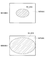
- the partial composition unit may generate the partial composite image in which a peripheral portion of the superimposed image is replaced with a peripheral portion of the normal light image. In this way, based on the hue contrast between the superimposed image assigned to the central portion of the partial composite image and the normal light image surrounding the superimposed image, the observer can determine whether the imaging range is the region of interest. Can be easily recognized.
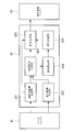
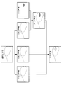
- FIG. 1 is an overall configuration diagram of an endoscope apparatus according to an embodiment of the present invention. It is a block diagram of the image processing unit (endoscope image processing apparatus) in the endoscope apparatus of FIG. It is a figure explaining the production
- the endoscope apparatus 1 is for observing a normal light image and a fluorescent image of a living tissue (subject) S in which a region of interest such as a lesion is labeled with a fluorescent dye.
- the endoscope apparatus 1 can be inserted into a body and a light source unit 2 that outputs normal light and excitation light (special light), and normal light and excitation light can be inserted into a living tissue S in the body.
- a light source unit 2 that outputs normal light and excitation light (special light), and normal light and excitation light can be inserted into a living tissue S in the body.
- an image generated by the processor 4 connected to the processor 4 and the processor 4 for generating an image from the image signal acquired by the inserter 3.
- Display device 5 5.
- the light source unit 2 includes a light source 21 that emits broadband light such as white light, a filter unit 22 that selectively transmits normal light and excitation light among the light emitted from the light source 21, and the filter unit 22 And a coupling lens 23 for converging normal light or excitation light transmitted through the light.
- the filter unit 22 includes a turret having a normal light filter that selectively transmits normal light that is broadband visible light, and an excitation light filter that selectively transmits narrow-band excitation light.
- the filter unit 22 rotates the turret according to the control by the timing control unit 44 described later, and alternately arranges the normal light filter and the excitation light filter on the output optical axis of the light source 21. Thereby, the normal light and the excitation light are alternately output from the light source unit 2.
- the insertion unit 3 is provided at the illumination unit 6 that irradiates the normal tissue and the excitation light output from the light source unit 2 toward the living tissue S from the distal end 3a of the insertion unit 3, and the distal end 3a of the insertion unit 3. And an image pickup unit 7 for photographing S.
- the illumination unit 6 includes a light guide fiber 61 disposed over almost the entire length of the insertion portion 3 in the longitudinal direction, and an illumination optical system 62 provided at the distal end 3a of the insertion portion 3.
- the light guide fiber 61 guides the light converged by the coupling lens 23 from the proximal end to the distal end.
- the illumination optical system 62 diffuses normal light and excitation light emitted from the distal end of the light guide fiber 61 and irradiates the living tissue S facing the distal end 3 a of the insertion portion 3.
- the imaging unit 7 includes an objective lens 71 that collects light from the living tissue S, a converging lens 72 that converges the light collected by the objective lens 71, and an imaging element 73 that captures the light converged by the converging lens 72. It has.
- Reference numeral 74 denotes an excitation light cut filter that blocks excitation light and transmits light other than excitation light.
- the insertion part 3 may be a rigid type.
- the image sensor 73 is, for example, a color CCD or a color CMOS.
- the image sensor 73 receives light incident from the objective lens 71, photoelectrically converts the received light to generate an image signal, and transmits the generated image signal to the processor 4.
- the processor 4 includes a data buffer 41 that temporarily holds an image signal received from the image sensor 73, an image processing unit (an endoscope image processing device) 42 that processes the image signal received from the data buffer 41, A display image buffer 43 that temporarily holds an image output from the image processing unit 42; a timing control unit 44 that synchronizes the operations of the buffers 41 and 43, the image processing unit 42, the filter unit 22, and the image sensor 73; It has.
- Reference numeral 45 denotes an amplifier that amplifies the image signal output from the image sensor 73
- reference numeral 46 denotes a gain controller (AGC)
- reference numeral 47 converts an analog image signal to a digital signal.
- Reference numeral 48 denotes a DA converter that converts a digital image signal of an image output from the display image buffer 43 into an analog image signal.
- the timing control unit 44 causes the image sensor 73 to perform normal light exposure when a normal light filter is disposed on the output optical axis of the light source 21 and the normal tissue S is irradiated with the normal light, and the output of the light source 21 is output.
- the imaging element 73 executes the exposure of the fluorescence so that the normal light image signal and the fluorescence image signal are alternately displayed. 73.
- the data buffer 41 temporarily holds the normal light image signal and the fluorescence image signal received from the image sensor 73 and transmits the pair of normal light image signal and the fluorescence image signal to the image processing unit 42.
- the image processing unit 42 includes a normal light image generation unit 421 that generates a normal light image from the normal light image signal, and a fluorescent image generation that generates a fluorescent image (special light image) from the fluorescent image signal.
- Unit (special light image generation unit) 422 a superimposed image generation unit 423 that generates a superimposed image by superimposing a fluorescent image on the normal light image, and a ratio calculation unit 424 that calculates a background ratio of the background region in the entire superimposed image.
- a partial synthesis unit (image output unit) 425 that allocates a normal light image to a part of the superimposed image to generate a partial synthesized image, and an image output from the image processing unit 42 to the display device 5 as a superimposed image and a partial synthesized image
- a display switching unit 426 that switches between and.
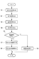
- FIG. 3 shows a superimposed image generation process in the image processing unit 42.
- the normal light image generation unit 421 receives the normal light image signal from the data buffer 41 and generates a normal light image.
- a normal light image signal acquired by photographing broadband normal light includes three color image signals, that is, a red (R) image signal, a green (G) image signal, and a blue (B) image signal. Therefore, the normal light image generation unit 421 generates an R component image, a G component image, and a B component image that constitute an RGB color normal light image from the R image signal, the G image signal, and the B image signal, respectively.
- the normal light image generation unit 421 transmits the R, G, and B component images to the superimposed image generation unit 423.
- the fluorescence image generation unit 422 receives the fluorescence image signal from the data buffer 41, generates a fluorescence image, and transmits the generated fluorescence image to the superimposed image generation unit 423.
- the fluorescent image includes a fluorescent region (a hatched region) and a background region.
- the fluorescent region is a region having a high luminance value corresponding to the region of interest.
- the background region is a region having a low luminance value corresponding to a region other than the region of interest of the living tissue S.
- Each component image and fluorescent image of the normal light image are composed of a large number of pixels arranged in a two-dimensional matrix.
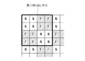
- the superimposed image generation unit 423 generates a blend image obtained by mixing some pixels of the G component image and some pixels of the fluorescence image from the G component image and the fluorescence image. Specifically, as illustrated in FIG. 4, the superimposed image generation unit 423 stores a blend pattern that defines the arrangement of the pixel “N” of the G component image and the pixel “F” of the fluorescent image.
- the blend pattern is a square lattice arrangement pattern in which “N” and “F” are alternately arranged in a checkered pattern in the row direction and the column direction in units of one pixel.
- the superimposed image generation unit 423 generates a blend image by replacing a pixel corresponding to “F” of the blend pattern among all the pixels of the G component image with a pixel of the fluorescence image.
- the superimposed image generation unit 423 generates a color superimposed image by using the blend image instead of the G component image and color-combining the blend image, the R component image, and the B component image.
- the superimposed image generation unit 423 transmits the generated superimposed image to the ratio calculation unit 424 and the partial synthesis unit 425.
- the ratio calculation unit 424 selects a background area based on the hue of each pixel of the superimposed image, and calculates the background ratio that the background area occupies in the entire superimposed image. Specifically, the ratio calculation unit 424 is provided with a setting range for each of the R signal value, the G signal value, and the B signal value.
- the setting range is a range of R, G, and B signal values that constitute a hue that is the same as or similar to the hue of the living tissue S. For example, when the R, G, and B signal values have 255 gradations, the range of the R signal value is 150 or more and 200 or less, the range of the G signal value is 100 or more and 150 or less, and the range of the B signal value is 50. More than 100.
- the ratio calculation unit 424 selects a pixel in which the R signal value, the G signal value, and the B signal value of each pixel of the superimposed image are within the setting range as the background region, and the number of selected pixels is the total number of pixels of the superimposed image. Is calculated as a background ratio, and the calculated background ratio is transmitted to the display switching unit 426.
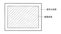
- the partial synthesis unit 425 generates a partial synthesized image in which a part of the normal light image is synthesized with a part of the superimposed image by performing a partial synthesis process on the superimposed image. Specifically, the partial composition unit 425 replaces the peripheral portion in the normal light image with the peripheral portion in the superimposed image, whereby the superimposed image is assigned to the central portion, and the normal light image is applied to the peripheral portion surrounding the superimposed image. A partial composite image to which is assigned is generated.
- the display switching unit 426 determines whether or not the partial synthesis unit 425 executes the partial synthesis process on the superimposed image.
- the partial synthesis unit 425 outputs either the superimposed image or the partial synthesized image to the display image buffer 43 according to whether or not the partial synthesis process is executed.
- the display switching unit 426 determines whether or not to cause the partial synthesis unit 425 to execute the partial synthesis process, and thereby the image to be displayed on the display device 5 is the superimposed image. Switch between partial composite images.
- the display switching unit 426 does not cause the partial synthesis unit 425 to execute the partial synthesis process when the background ratio is greater than a predetermined threshold, and performs partial synthesis when the background ratio is equal to or less than the predetermined threshold.
- the unit 425 is caused to execute partial synthesis processing.
- the predetermined threshold is, for example, 20%.
- the display image buffer 43 temporarily holds the superimposed image or the partial synthesized image received from the partial synthesizer 425, and displays the superimposed image or the partial synthesized image via the DA converter 48 with a certain time interval. Output to.
- the operation of the image processing unit 42 configured as described above and the endoscope apparatus 1 including the same will be described.
- a fluorescent substance that accumulates in the region of interest is administered to the biological tissue S in advance.
- the insertion portion 3 is inserted into the body, the distal end 3a is disposed opposite to the living tissue S, and normal light and excitation light are alternately irradiated from the distal end 3a of the insertion portion 3 to the living tissue S by operation of the light source unit 2.
- normal light When normal light is irradiated onto the living tissue S, normal light reflected on the surface of the living tissue S is collected by the objective lens 71.
- the normal light collected by the objective lens 71 is converged on the imaging surface of the image sensor 73 by the converging lens 72 and is acquired as a normal light image signal by the image sensor 73.
- the fluorescent material included in the region of interest when the living tissue S is irradiated with excitation light, the fluorescent material included in the region of interest generates fluorescence, and the fluorescence and excitation light are collected by the objective lens 71. Only the fluorescence and excitation light collected by the objective lens 71 are extracted by the excitation light cut filter 74. The extracted fluorescence is converged on the imaging surface of the imaging element 73 by the converging lens 72 and acquired as a fluorescence image signal by the imaging element 73. The normal light image signal and the fluorescence image signal acquired alternately by the image sensor 73 as described above are transmitted to the processor 4.
- the normal light image signal and the fluorescence image signal are input to the data buffer 41 via the amplifier 45, the AGC 46 and the AD converter 47, and the pair of normal light image signal and the fluorescence image signal are processed from the data buffer 41. Input to the unit 42.
- the normal light image signal is input to the normal light image generation unit 421 to generate the normal light image (step S1), and the fluorescence image signal is converted to the fluorescence image generation unit 422. To generate a fluorescent image (step S2).
- the pixels of the G component image and the pixels of the fluorescence image are uniformly blended throughout by replacing some of the pixels in the G component image with the pixels of the fluorescence image.
- a blend image is generated.
- the blend image includes both the image of the living tissue S in the G component image and the fluorescence image in the fluorescence image.
- the blended image is color-synthesized with the R component image and the B component image to generate a superimposed image (step S3).
- the ratio calculation unit 424 calculates the background ratio of the superimposed image (step S4), and based on the calculated background ratio, the display switching unit 426 determines whether to perform partial synthesis processing on the superimposed image. (Step S5).
- Step S6 the partial synthesis process is not executed (NO in step S5), and the superimposed image input from the superimposed image generation unit 423 to the partial synthesis unit 425 is output and displayed on the display device 5 through the display image buffer 43 as it is.
- the partial synthesis process is not executed (NO in step S5), and the superimposed image input from the superimposed image generation unit 423 to the partial synthesis unit 425 is output and displayed on the display device 5 through the display image buffer 43 as it is. (Step S6). At this time, based on the color contrast between the greenish fluorescent region and the red or yellowish background region, the observer can easily view the fluorescent region in the superimposed image displayed on the display device 5. Can be recognized.
- step S5 the partial composition process is executed (YES in step S5, step S7), and the partial composite image is output from the partial composition unit 425 to the display device 5 via the display image buffer 43 and displayed on the display device 5. (Step S8).
- the partial composite image is displayed on the display device 5 instead of the superimposed image.
- the partial composite image includes a superimposed image of a fluorescent region having a green color and a part of a normal light image of the biological tissue S having a red color or a yellow color. Therefore, there is an advantage that the observer can easily recognize that the current observation range is the region of interest based on the color contrast between the superimposed image and the normal light image.
- the blend image is an image in which the pixels of the G component image and the pixels of the fluorescence image are blended so as to be mixed in a substantially uniform distribution over the entire blend image, and the fluorescence image does not depend on the gradation value.
- the whole is synthesized into a blended image substantially uniformly. Therefore, not only the fluorescent region having a sufficiently high gradation value but also the fluorescent region having a relatively low gradation value in the fluorescent region is synthesized with the blend image. Accordingly, there is an advantage that a superimposed image in which all of the fluorescent regions to be noticed by the observer are displayed can be generated.
- the gradation value of each pixel of the blend image is the gradation value of the pixel of the G color component image or the gradation value of the pixel of the fluorescent image itself.
- the partial composite image is generated by replacing the peripheral portion of the superimposed image with the peripheral portion of the normal light image.
- the allocation of the normal light image in the partial composite image is not limited to this. It is sufficient that at least a part of the normal light image is displayed on a part of the partial composite image.
- a partial composite image in which a reduced image of the entire normal light image is assigned to any of the four corners of the superimposed image may be generated. Even in this case, the observer can easily recognize the fluorescent region based on the color contrast between the superimposed image and the normal light image.
- the ratio calculation unit 424 specifies the background area in the superimposed image based on the hue, but instead, the background area may be specified based on another index. For example, a ratio of the R signal value, the G signal value, and the B signal value of each pixel may be used. Alternatively, the signal of each pixel may be converted from the RGB format to the MJL format, and values of saturation, luminance, and brightness may be used.
- the ratio calculation unit 424 calculates the region-of-interest ratio that the region of interest occupies in the entire superimposed image instead of the background ratio, and the display switching unit 426 replaces the background ratio with the region-of-interest ratio.
- the image output from the partial synthesis unit 425 may be switched.
- the region-of-interest ratio can be calculated as, for example, the ratio of the portion other than the background ratio to the entire superimposed image.
- a region of interest is selected from the superimposed image based on the hue of each pixel of the superimposed image, and the ratio of the number of pixels of the selected region of interest to the total number of pixels of the superimposed image is the region of interest. You may calculate as a ratio.
- the blend image in which the pixels of the G component image and the pixels of the fluorescence image are arranged in a checkered pattern is generated. Any pattern may be used as long as the distribution of the pixels of the fluorescent image is substantially uniform.
- the blend patterns in FIGS. 7 and 8 are periodic arrangement patterns in which the minimum repeating unit consisting of “N” and “F” is repeated in the row direction and the column direction.
- the alternating cycle of “N” and “F” in the row direction and the alternating cycle of “N” and “F” in the column direction are different from each other.
- the alternating period of “N” and “F” in the row direction and the alternating period of “N” and “F” in the column direction are the same.
- the superimposed image generation unit 423 may randomly select the pixel to be replaced with the pixel of the fluorescent image from all the pixels of the G component image. In this case, the superimposed image generation unit 423 selects pixels substantially uniformly from the entire G component image so that the position of the pixel selected in the G component image is not biased. Further, instead of the G component image, an R component image or a B component image may be used for generating a blend image.
- the background ratio is equal to or less than a predetermined threshold.
- the observation distance is equal to or less than a predetermined threshold.
- the insertion unit 3 is provided with a distance measurement unit (not shown) that measures the observation distance from the distal end of the insertion unit 3 to the living tissue S.
- a distance measurement unit (not shown) that measures the observation distance from the distal end of the insertion unit 3 to the living tissue S.
- an observation distance input unit 427 for inputting the measured observation distance from the distance measurement unit is provided in the image processing unit 42.
- the distance measurement unit is, for example, an optical distance sensor provided at the distal end of the insertion unit 3.
- the display switching unit 426 receives the observation distance measured by the distance measurement unit via the observation distance input unit 427, and executes partial synthesis processing on the partial synthesis unit 425 only when the observation distance is equal to or less than a predetermined threshold.
- FIG. 10 shows the relationship between the observation distance and the region of interest occupied by the region of interest in the entire superimposed image.
- the region-of-interest ratio decreases when the observation distance is large, and the region-of-interest ratio increases when the observation distance is small.
- the region-of-interest ratio of the superimposed image has a correlation with the observation distance, it can be determined based on the observation distance whether the region-of-interest ratio of the superimposed image is equal to or greater than a predetermined value. it can.
- the partial synthesis unit 425 may adjust the color of the superimposed image in the partial synthesized image. For example, the partial synthesis unit 425 may increase the G signal value of the superimposed image. By doing in this way, since the fluorescent region in the partial composite image has a stronger green color, the observer can more easily recognize the fluorescent region.
- the normal light image signal and the fluorescence image signal are alternately obtained by using a single image sensor 73, but instead of this, two image sensors are provided and the normal light image signal is provided. And the fluorescence image signal may be acquired using separate image sensors.
- the living tissue S may be irradiated with normal light and excitation light at the same time.
- the excitation light and the fluorescence image for exciting the fluorescent material have been described as an example of the special light and the special light image.
- the types of the special light and the special light image are not limited thereto, and are of interest. It can be appropriately changed according to the type of region.
- the region of interest is a blood vessel
- special light absorbed by a blood component in the blood vessel may be used.
- an infrared light image may be acquired using infrared light
- an NBI image may be acquired using blue narrow band light and green narrow band light.
- Endoscope apparatus 42 Image processing unit (Image processing apparatus for endoscopes) 421 Normal light image generation unit 422 Fluorescence image generation unit (special light image generation unit) 423 superimposed image generation unit 424 ratio calculation unit 425 partial synthesis unit (image output unit) 426 Display switching unit 427 Observation distance input unit
Abstract
本発明の内視鏡用画像処理装置(42)は、被写体の通常光画像および特殊光画像をそれぞれ生成する通常光画像生成部(421)および特殊光画像生成部(422)と、通常光画像の一の色成分画像の画素と特殊光画像の画素とを混合したブレンド画像を生成し、ブレンド画像と他の色成分画像とを合成して重畳画像を生成する重畳画像生成部(433)と、重畳画像の一部分に通常光画像を合成して部分合成画像を生成する部分合成部(425)と、画像出力部(425)と、関心領域または該関心領域を除く被写体の背景領域が重畳画像全体に占める割合に基づき画像出力部(425)からの出力を重畳画像と部分合成画像との間で切り替える表示切替部(426)とを備える。
Description
本発明は、内視鏡用画像処理装置に関するものである。
従来、白色光画像のような通常光画像と、蛍光画像のような特殊光画像とを取得し、通常光画像と特殊光画像とを重畳表示する内視鏡装置が知られている(例えば、特許文献1,2参照。)。通常光画像と特殊光画像とを重畳する方法として、特許文献1では、通常光画像を構成するR、G、Bの3色の色成分画像の内の1つに特殊光画像を加算しており、特許文献2では、特殊光画像から高い階調値を有する関心領域を抽出し、抽出された関心領域を通常光画像に加算している。
しかしながら、特許文献1の重畳方法を用いた場合、蛍光画像の階調値が一の色成分画像の階調値に加算されて該一の色成分画像の階調値が底上げされることによって、重畳画像の色調が全体的に、特殊光画像を重畳した成分画像の色に偏り、重畳画像の色調が通常光画像の色調とは異なってしまうという問題がある。さらに、蛍光画像はSN比が低いことが多く、蛍光画像のノイズがそのまま重畳画像に反映されてしまうという問題がある。
特許文献2の重畳方法を用いた場合、関心領域の内、抽出基準を満たさない比較的低い階調値を有するものは、観察者にとって注目すべき領域であるにも関わらず、特殊光画像から抽出されずに重畳画像には表示されない可能性がある。
本発明は、上述した事情に鑑みてなされたものであって、色調の変化およびノイズが少なく、かつ、特殊光画像内の関心領域が表示された重畳画像を生成することができる内視鏡用画像処理装置を提供することを目的とする。
上記目的を達成するため、本発明は以下の手段を提供する。
本発明は、広帯域の可視光が照射された被写体の通常光画像を生成する通常光画像生成部と、前記被写体内の関心領域と特異的に作用する狭帯域の特殊光が照射された前記被写体の特殊光画像を生成する特殊光画像生成部と、前記通常光画像を構成する複数の色成分画像の内のいずれか1つと前記特殊光画像とを合成してブレンド画像を生成し、生成された前記ブレンド画像と前記複数の色成分画像の内の他の色成分画像とを合成してカラーの重畳画像を生成する重畳画像生成部と、該重畳画像生成部によって生成された前記重畳画像の一部分に前記通常光画像の少なくとも一部分を合成して部分合成画像を生成する部分合成部と、前記重畳画像および前記部分合成画像のうちいずれかを表示装置に出力する画像出力部と、前記関心領域が前記重畳画像全体に占める関心領域割合および前記関心領域を除く前記被写体の背景領域が前記重畳画像全体に占める背景割合のうちいずれか一方に基づき、前記画像出力部からの出力を前記重畳画像と前記部分合成画像との間で切り替える表示切替部とを備え、前記重畳画像生成部が、前記いずれか1つの色成分画像の画素の内の一部の画素を選択し、選択された一部の画素を前記特殊光画像の対応する画素に置換することによって前記ブレンド画像を生成するとともに、前記ブレンド画像の全体にわたって前記いずれか1つの色成分画像の画素および前記特殊光画像の画素の分布が略均一となるように、前記いずれか1つの色成分画像の一部の画素を前記特殊光画像の画素に置換する内視鏡用画像処理装置を提供する。
本発明は、広帯域の可視光が照射された被写体の通常光画像を生成する通常光画像生成部と、前記被写体内の関心領域と特異的に作用する狭帯域の特殊光が照射された前記被写体の特殊光画像を生成する特殊光画像生成部と、前記通常光画像を構成する複数の色成分画像の内のいずれか1つと前記特殊光画像とを合成してブレンド画像を生成し、生成された前記ブレンド画像と前記複数の色成分画像の内の他の色成分画像とを合成してカラーの重畳画像を生成する重畳画像生成部と、該重畳画像生成部によって生成された前記重畳画像の一部分に前記通常光画像の少なくとも一部分を合成して部分合成画像を生成する部分合成部と、前記重畳画像および前記部分合成画像のうちいずれかを表示装置に出力する画像出力部と、前記関心領域が前記重畳画像全体に占める関心領域割合および前記関心領域を除く前記被写体の背景領域が前記重畳画像全体に占める背景割合のうちいずれか一方に基づき、前記画像出力部からの出力を前記重畳画像と前記部分合成画像との間で切り替える表示切替部とを備え、前記重畳画像生成部が、前記いずれか1つの色成分画像の画素の内の一部の画素を選択し、選択された一部の画素を前記特殊光画像の対応する画素に置換することによって前記ブレンド画像を生成するとともに、前記ブレンド画像の全体にわたって前記いずれか1つの色成分画像の画素および前記特殊光画像の画素の分布が略均一となるように、前記いずれか1つの色成分画像の一部の画素を前記特殊光画像の画素に置換する内視鏡用画像処理装置を提供する。
本発明によれば、通常光画像生成部によって生成されたカラーの通常光画像は、一の色成分画像と他の色成分画像とに分離され、一の色成分画像が特殊光画像生成部によって生成された特殊光画像と合成されることによってブレンド画像が生成される。生成されたブレンド画像は、重畳画像生成部によって他の色成分画像と色合成される。これにより、特殊光画像を通常光画像に重畳した重畳画像が得られる。
この場合に、特殊光画像は、一部の領域のみを抽出する処理を施されることなく、全体が略均一にブレンド画像に合成される。したがって、特殊光画像内の関心領域を重畳画像に表示させることができる。さらに、ブレンド画像において一の色成分画像の画素と特殊光画像の画素とをそのまま混在させることによって、一の色成分画像に対するブレンド画像の階調値の変化が低減され、かつ、特殊光画像に含まれていたノイズがブレンド画像においては低減される。これにより、通常光画像に対して色調の変化およびノイズが少ない重畳画像を生成することができる。
また、関心領域が重畳画像全体に占める関心領域割合または関心領域を除く被写体の背景領域が重畳画像全体に占める背景割合に応じて、表示装置に表示される画像が重畳画像と部分合成画像との間で表示切替部によって切り替えられる。重畳画像の一部分のみに関心領域が存在する場合には、関心領域と該関心領域を取り囲む背景領域との間の色のコントラストに基づいて、観察者は、重畳画像内の関心領域を容易に認識することができる。しかし、重畳画像の大部分が関心領域である場合には、観察者は、重畳画像の撮影範囲が関心領域であるのか否かを判断することが難しい。本発明によれば、重畳画像の大部分を関心領域が占めるときには部分合成画像を表示させることによって、観察者は、部分合成画像内の通常光画像に基づいて現在の観察範囲が関心領域であるか否かを容易に認識することができる。
上記発明においては、前記背景割合を算出する割合算出部を備え、前記表示切替部は、前記割合算出部によって算出された背景割合が所定の閾値よりも大きいときに前記重畳画像を前記画像出力部から出力させ、前記背景割合が所定の閾値以下であるときに前記部分合成画像を前記画像出力部から出力させてもよい。あるいは、上記発明においては、前記関心領域割合を算出する割合算出部を備え、前記表示切替部は、前記割合算出部によって算出された前記関心領域割合が所定の閾値未満のときに前記重畳画像を前記画像出力部から出力させ、前記関心領域割合が前記閾値以上のときに前記部分合成画像を前記画像出力部から出力させてもよい。
関心領域割合が大きい程、背景割合は小さくなる。したがって、関心領域割合または背景割合に基づいて、関心領域割合が所定値以上となる条件、つまり観察者にとって関心領域の判断が困難となる条件であるか否かを判断し、重畳画像および部分合成画像の内、観察に適した方を表示させることができる。
関心領域割合が大きい程、背景割合は小さくなる。したがって、関心領域割合または背景割合に基づいて、関心領域割合が所定値以上となる条件、つまり観察者にとって関心領域の判断が困難となる条件であるか否かを判断し、重畳画像および部分合成画像の内、観察に適した方を表示させることができる。
上記発明においては、前記割合算出部が、前記重畳画像の全画素の内、所定の色相を有する画素の割合を前記背景割合として算出してもよい。
重畳画像内の関心領域の色相はブレンド画像の色に偏るので、重畳画像の各画素の色相に基づいて背景領域を特定し、背景割合を正確に算出することができる。
重畳画像内の関心領域の色相はブレンド画像の色に偏るので、重畳画像の各画素の色相に基づいて背景領域を特定し、背景割合を正確に算出することができる。
上記発明においては、前記被写体までの観察距離が入力される観察距離入力部を備え、前記表示切替部は、前記観察距離入力部に入力された観察距離が所定の閾値よりも大きいときに前記重畳画像を前記画像出力部から出力させ、前記観察距離が所定の閾値以下であるときに前記部分合成画像を前記画像出力部から出力させてもよい。
このようにすることで、観察距離が短いときには関心領域割合が大きくなるので、観察距離に基づいて、関心領域割合および背景割合を判断することができる。
このようにすることで、観察距離が短いときには関心領域割合が大きくなるので、観察距離に基づいて、関心領域割合および背景割合を判断することができる。
上記発明においては、前記部分合成部が、前記重畳画像の周縁部分を前記通常光画像の周縁部分に置換した前記部分合成画像を生成してもよい。
このようにすることで、部分合成画像の中央部分に割り付けられた重畳画像と該重畳画像を囲む通常光画像との色相のコントラストに基づいて、観察者は、撮影範囲が関心領域であるか否かを容易に認識することができる。
このようにすることで、部分合成画像の中央部分に割り付けられた重畳画像と該重畳画像を囲む通常光画像との色相のコントラストに基づいて、観察者は、撮影範囲が関心領域であるか否かを容易に認識することができる。
本発明によれば、色調の変化およびノイズが少なく、かつ、特殊光画像内の関心領域が表示された重畳画像を生成することができるという効果を奏する。
本発明の一実施形態に係る内視鏡装置1について図面を参照して説明する。
本実施形態に係る内視鏡装置1は、病変部のような関心領域が蛍光色素で標識された生体組織(被写体)Sの通常光画像および蛍光画像を観察するためのものである。
内視鏡装置1は、図1に示されるように、通常光および励起光(特殊光)を出力する光源ユニット2と、体内に挿入可能であり、体内の生体組織Sに通常光および励起光を照射して生体組織Sの画像信号を取得する挿入部3と、該挿入部3によって取得された画像信号から画像を生成するプロセッサ4と、該プロセッサ4と接続されプロセッサ4によって生成された画像を表示する表示装置5とを備えている。
本実施形態に係る内視鏡装置1は、病変部のような関心領域が蛍光色素で標識された生体組織(被写体)Sの通常光画像および蛍光画像を観察するためのものである。
内視鏡装置1は、図1に示されるように、通常光および励起光(特殊光)を出力する光源ユニット2と、体内に挿入可能であり、体内の生体組織Sに通常光および励起光を照射して生体組織Sの画像信号を取得する挿入部3と、該挿入部3によって取得された画像信号から画像を生成するプロセッサ4と、該プロセッサ4と接続されプロセッサ4によって生成された画像を表示する表示装置5とを備えている。
光源ユニット2は、白色光のような広帯域光を発する光源21と、該光源21から発せられた光の内、通常光および励起光を択一的に透過させるフィルタユニット22と、該フィルタユニット22を透過した通常光または励起光を収束させるカップリングレンズ23とを備えている。フィルタユニット22は、広帯域の可視光である通常光を選択的に透過させる通常光フィルタと、狭帯域の励起光を選択的に透過させる励起光フィルタとを有するターレットを備えている。フィルタユニット22は、後述するタイミング制御部44による制御に従ってターレットを回転させて通常光フィルタおよび励起光フィルタを交互に光源21の出力光軸上に配置する。これにより、光源ユニット2からは通常光と励起光とが交互に出力されるようになっている。
挿入部3は、光源ユニット2から出力された通常光および励起光を挿入部3の先端3aから生体組織Sに向けて照射する照明ユニット6と、挿入部3の先端3aに設けられ、生体組織Sを撮影する撮像ユニット7とを備えている。
照明ユニット6は、挿入部3の長手方向のほぼ全長にわたって配置されたライトガイドファイバ61と、挿入部3の先端3aに設けられた照明光学系62とを備えている。ライトガイドファイバ61は、カップリングレンズ23によって収束された光をその基端から先端まで導光する。照明光学系62は、ライトガイドファイバ61の先端から射出された通常光および励起光を拡散させ、挿入部3の先端3aに対向する生体組織Sに照射する。
撮像ユニット7は、生体組織Sからの光を集める対物レンズ71と、該対物レンズ71によって集められた光を収束させる収束レンズ72と、収束レンズ72によって収束された光を撮影する撮像素子73とを備えている。符号74は、励起光を遮断し、励起光以外の光を透過させる励起光カットフィルタである。
なお、本実施形態においては、先端部に撮像素子73が設けられた軟性型の挿入部3について説明するが、挿入部3は硬性型であってもよい。
なお、本実施形態においては、先端部に撮像素子73が設けられた軟性型の挿入部3について説明するが、挿入部3は硬性型であってもよい。
撮像素子73は、例えば、カラーCCDまたはカラーCMOSである。撮像素子73は、対物レンズ71から入射した光を受光し、受光した光を光電変換して画像信号を生成し、生成された画像信号をプロセッサ4へ送信する。
プロセッサ4は、撮像素子73から受信した画像信号を一時的に保持するデータバッファ41と、該データバッファ41から受信した画像信号を処理する画像処理ユニット(内視鏡用画像処理装置)42と、該画像処理ユニット42から出力された画像を一時的に保持する表示画像バッファ43と、各バッファ41,43、画像処理ユニット42、フィルタユニット22および撮像素子73の動作を同期させるタイミング制御部44とを備えている。符号45は、撮像素子73から出力された画像信号を増幅する増幅器であり、符号46は、利得制御器(AGC)であり、符号47は、アナログ信号の画像信号をデジタル信号の画像信号へ変換するAD変換器であり、符号48は、表示画像バッファ43から出力された画像のデジタルの画像信号をアナログの画像信号へ変換するDA変換器である。
タイミング制御部44は、光源21の出力光軸上に通常光フィルタが配置されて生体組織Sに通常光が照射されているときに撮像素子73に通常光の露光を実行させ、光源21の出力光軸上に励起光フィルタが配置されて生体組織Sに励起光が照射されているときに撮像素子73に蛍光の露光を実行させることによって、通常光画像信号および蛍光画像信号を交互に撮像素子73に取得させる。
データバッファ41は、撮像素子73から受信した通常光画像信号および蛍光画像信号を一時的に保持し、一対の通常光画像信号および蛍光画像信号を画像処理ユニット42に送信する。
画像処理ユニット42は、図2に示されるように、通常光画像信号から通常光画像を生成する通常光画像生成部421と、蛍光画像信号から蛍光画像(特殊光画像)を生成する蛍光画像生成部(特殊光画像生成部)422と、通常光画像に蛍光画像を重畳して重畳画像を生成する重畳画像生成部423と、背景領域が重畳画像全体に占める背景割合を算出する割合算出部424と、重畳画像の一部分に通常光画像を割り付けて部分合成画像を生成する部分合成部(画像出力部)425と、画像処理ユニット42から表示装置5へ出力される画像を重畳画像と部分合成画像との間で切り替える表示切替部426とを備えている。
図3は、画像処理ユニット42における重畳画像の生成処理を示している。
通常光画像生成部421は、データバッファ41から通常光画像信号を受信し、通常光画像を生成する。広帯域の通常光を撮影して取得された通常光画像信号は、3色の画像信号、すなわち赤(R)画像信号、緑(G)画像信号および青(B)画像信号から構成されている。したがって、通常光画像生成部421は、R画像信号、G画像信号およびB画像信号から、RGBカラーの通常光画像を構成するR成分画像、G成分画像およびB成分画像をそれぞれ生成する。通常光画像生成部421は、R、GおよびB成分画像を重畳画像生成部423に送信する。
通常光画像生成部421は、データバッファ41から通常光画像信号を受信し、通常光画像を生成する。広帯域の通常光を撮影して取得された通常光画像信号は、3色の画像信号、すなわち赤(R)画像信号、緑(G)画像信号および青(B)画像信号から構成されている。したがって、通常光画像生成部421は、R画像信号、G画像信号およびB画像信号から、RGBカラーの通常光画像を構成するR成分画像、G成分画像およびB成分画像をそれぞれ生成する。通常光画像生成部421は、R、GおよびB成分画像を重畳画像生成部423に送信する。
蛍光画像生成部422は、データバッファ41から蛍光画像信号を受信し、蛍光画像を生成し、生成された蛍光画像を重畳画像生成部423に送信する。蛍光画像は、図3に示されるように、蛍光領域(ハッチングが掛けられた領域)と背景領域とを含む。蛍光領域は、関心領域に対応し高い輝度値を有する領域である。背景領域は、生体組織Sの関心領域以外の領域に対応し低い輝度値を有する領域である。
通常光画像の各成分画像および蛍光画像は、行列状に2次元配列した多数の画素からなる。
通常光画像の各成分画像および蛍光画像は、行列状に2次元配列した多数の画素からなる。
重畳画像生成部423は、G成分画像および蛍光画像から、G成分画像の一部の画素と蛍光画像の一部の画素とを混合したブレンド画像を生成する。具体的には、重畳画像生成部423には、図4に示されるように、G成分画像の画素「N」と蛍光画像の画素「F」の配列を規定したブレンドパターンが記憶されている。ブレンドパターンは、「N」および「F」が、1画素単位で交互に行方向および列方向に市松模様状に配列した正方格子配列パターンである。重畳画像生成部423は、G成分画像の全画素の内、ブレンドパターンの「F」に対応する画素を蛍光画像の画素に置換することによって、ブレンド画像を生成する。
次に、重畳画像生成部423は、ブレンド画像をG成分画像の代わりとして用い、ブレンド画像とR成分画像とB成分画像とをカラー合成することによって、カラーの重畳画像を生成する。重畳画像生成部423は、生成した重畳画像を割合算出部424および部分合成部425へ送信する。
割合算出部424は、重畳画像の各画素の色相に基づいて背景領域を選択し、背景領域が重畳画像全体に占める背景割合を算出する。具体的には、割合算出部424には、R信号値、G信号値およびB信号値の各々に対する設定範囲が設けられている。設定範囲は、生体組織Sの色相と同一または類似する色相を構成するようなR、GおよびB信号値の範囲である。例えば、R、GおよびB信号値が255階調を有する場合、R信号値の範囲は150以上200以下であり、G信号値の範囲は100以上150以下であり、B信号値の範囲は50以上100以上である。
割合算出部424は、重畳画像の各画素のR信号値、G信号値およびB信号値が設定範囲内である画素を背景領域として選択し、選択された画素の数が重畳画像の全画素数に占める割合を背景割合として算出し、算出された背景割合を表示切替部426に送信する。
部分合成部425は、図5に示されるように、重畳画像に部分合成処理を施して重畳画像の一部分に通常光画像の一部分が合成された部分合成画像を生成する。具体的には、部分合成部425は、通常光画像内の周縁部分を重畳画像内の周縁部分に置き換えることによって、中央部分に重畳画像が割り付けられ、該重畳画像を取り囲む周縁部分に通常光画像が割り付けられた部分合成画像を生成する。
部分合成部425が重畳画像に対して部分合成処理を実行するか否かは、表示切替部426によって判断される。部分合成部425は、部分合成処理の実行の有無に応じて、重畳画像および部分合成画像のうちのいずれかを表示画像バッファ43に出力する。
部分合成部425が重畳画像に対して部分合成処理を実行するか否かは、表示切替部426によって判断される。部分合成部425は、部分合成処理の実行の有無に応じて、重畳画像および部分合成画像のうちのいずれかを表示画像バッファ43に出力する。
表示切替部426は、割合算出部424から受信した背景割合に基づいて、部分合成部425に部分合成処理を実行させるか否かを判断し、それによって表示装置5に表示させる画像を重畳画像と部分合成画像との間で切り替える。
具体的には、表示切替部426は、背景割合が所定の閾値よりも大きい場合には部分合成部425に部分合成処理を実行させず、背景割合が所定の閾値以下である場合には部分合成部425に部分合成処理を実行させる。所定の閾値は、例えば、2割である。これにより、背景割合が所定の閾値よりも大きい場合には、重畳画像がそのまま部分合成部425から表示画像バッファ43に送信され、重畳画像が表示装置5に表示される。一方、背景割合が所定の閾値以下である場合には、部分合成画像が部分合成部425から表示画像バッファ43に送信され、部分合成画像が表示装置5に表示される。
表示画像バッファ43は、部分合成部425から受信した重畳画像または部分合成画像を一時的に保持し、重畳画像または部分合成画像を一定の時間間隔を空けてDA変換器48を介して表示装置5へ出力する。
次に、このように構成された画像処理ユニット42およびこれを備える内視鏡装置1の作用について説明する。
本実施形態に係る内視鏡装置1を用いて生体組織Sを観察するには、予め、関心領域に集積する蛍光物質を生体組織Sに投与しておく。
まず、体内に挿入部3を挿入して先端3aを生体組織Sに対向配置し、光源ユニット2の作動によって通常光および励起光を交互に挿入部3の先端3aから生体組織Sに照射する。
本実施形態に係る内視鏡装置1を用いて生体組織Sを観察するには、予め、関心領域に集積する蛍光物質を生体組織Sに投与しておく。
まず、体内に挿入部3を挿入して先端3aを生体組織Sに対向配置し、光源ユニット2の作動によって通常光および励起光を交互に挿入部3の先端3aから生体組織Sに照射する。
生体組織Sに通常光が照射されると、生体組織Sの表面において反射された通常光が対物レンズ71によって集められる。対物レンズ71によって集められた通常光は、収束レンズ72によって撮像素子73の撮像面に収束され、該撮像素子73によって通常光画像信号として取得される。
一方、生体組織Sに励起光が照射されると、関心領域に含まれる蛍光物質が蛍光を発生し、蛍光および励起光が対物レンズ71によって集められる。対物レンズ71によって集められた蛍光および励起光は、励起光カットフィルタ74において蛍光のみが抽出される。抽出された蛍光は、収束レンズ72によって撮像素子73の撮像面に収束されて、該撮像素子73によって蛍光画像信号として取得される。
以上のようにして撮像素子73によって交互に取得される通常光画像信号および蛍光画像信号は、プロセッサ4に送信される。
以上のようにして撮像素子73によって交互に取得される通常光画像信号および蛍光画像信号は、プロセッサ4に送信される。
プロセッサ4において、通常光画像信号および蛍光画像信号は、増幅器45、AGC46およびAD変換器47を介してデータバッファ41へ入力され、一対の通常光画像信号および蛍光画像信号がデータバッファ41から画像処理ユニット42へ入力される。
画像処理ユニット42においては、図6に示されるように、通常光画像信号が通常光画像生成部421に入力されて通常光画像が生成され(ステップS1)、蛍光画像信号が蛍光画像生成部422に入力されて蛍光画像が生成される(ステップS2)。
画像処理ユニット42においては、図6に示されるように、通常光画像信号が通常光画像生成部421に入力されて通常光画像が生成され(ステップS1)、蛍光画像信号が蛍光画像生成部422に入力されて蛍光画像が生成される(ステップS2)。
次に、重畳画像生成部423において、G成分画像の内、一部の画素を蛍光画像の画素に置換することによって、G成分画像の画素と蛍光画像の画素とが全体にわたって均一にブレンドされたブレンド画像が生成される。ブレンド画像には、G成分画像内の生体組織Sの像と、蛍光画像内の蛍光の像との両方が含まれる。続いて、重畳画像生成部423において、ブレンド画像がR成分画像およびB成分画像とカラー合成されて、重畳画像が生成される(ステップS3)。
次に、割合算出部424において、重畳画像の背景割合が算出され(ステップS4)、算出された背景割合に基づき、重畳画像に対して部分合成処理を施すか否かが表示切替部426によって判断される(ステップS5)。
ここで、挿入部3を体内に挿入する過程において、関心領域が見付かるまでは、重畳画像全体が背景領域となるので、背景割合が所定の閾値よりも大きくなる。したがって、部分合成処理は実行されず(ステップS5のNO)、重畳画像生成部423から部分合成部425に入力された重畳画像は、そのまま表示画像バッファ43を介して表示装置5に出力および表示される(ステップS6)。
関心領域が見付かった後、関心領域を離れた位置から通常観察しているときは、重畳画像の大部分を背景領域が占めるので、背景割合が所定の閾値よりも大きくなる。したがって、部分合成処理は実行されず(ステップS5のNO)、重畳画像生成部423から部分合成部425に入力された重畳画像は、そのまま表示画像バッファ43を介して表示装置5に出力および表示される(ステップS6)。このときに、緑色を帯びた蛍光領域と赤色または黄色を帯びた背景領域との間の色のコントラストに基づいて、観察者は、表示装置5に表示されている重畳画像内の蛍光領域を容易に認識することができる。
その後、関心領域を拡大観察するために関心領域に挿入部3を近接させていくと、重畳画像の大部分を関心領域が占めるようになり、背景割合が所定の閾値以下となる。したがって、部分合成処理が実行され(ステップS5のYES、ステップS7)、部分合成画像が、部分合成部425から表示画像バッファ43を介して表示装置5に出力され、該表示装置5に表示される(ステップS8)。
関心領域を拡大観察しているときには、重畳画像の略全体が蛍光領域となるため、観察者は、背景領域との色のコントラストを利用して蛍光領域を認識することができず、重畳画像の撮影範囲が関心領域であるのか否かを判断することが難しい。
本実施形態によれば、重畳画像内の大部分が関心領域であるときに、重畳画像に代えて部分合成画像が表示装置5に表示される。部分合成画像には、緑色を帯びた蛍光領域の重畳画像と、赤色または黄色を帯びた生体組織Sの通常光画像の一部分とが含まれる。したがって、観察者は、重畳画像と通常光画像との間の色のコントラストに基づいて、現在の観察範囲が関心領域であることを容易に認識することができるという利点がある。
本実施形態によれば、重畳画像内の大部分が関心領域であるときに、重畳画像に代えて部分合成画像が表示装置5に表示される。部分合成画像には、緑色を帯びた蛍光領域の重畳画像と、赤色または黄色を帯びた生体組織Sの通常光画像の一部分とが含まれる。したがって、観察者は、重畳画像と通常光画像との間の色のコントラストに基づいて、現在の観察範囲が関心領域であることを容易に認識することができるという利点がある。
また、ブレンド画像は、G成分画像の画素と蛍光画像の画素とが、ブレンド画像全体にわたって略均一な分布で混在するようにブレンドされた画像であり、蛍光画像は、階調値に依らずに全体が略均一にブレンド画像に合成される。したがって、蛍光領域の内、十分に高い階調値を有する蛍光領域のみならず、比較的低い階調値を有する蛍光領域もブレンド画像に合成される。これにより、観察者にとって注目すべき蛍光領域の全てが表示された重畳画像を生成することができるという利点がある。
さらに、ブレンド画像の各画素の階調値は、G色成分画像の画素の階調値または蛍光画像の画素の階調値そのものである。このようなブレンド画像を使用してカラー合成した重畳画像において、通常光画像の色調と略同一の色調を再現することができるという利点がある。さらに、蛍光画像のSN比が低く蛍光画像がノイズを含んでいたとしても、蛍光画像の画素とノイズの無いG成分画像の画素とをブレンドすることによって、ブレンド画像においてはノイズが低減される。これにより、ノイズの少ない重畳画像を得ることができるという利点がある。
本実施形態においては、重畳画像の周縁部分を通常光画像の周縁部分に置換した部分合成画像を生成することとしたが、部分合成画像における通常光画像の割り付けはこれに限定されるものではなく、部分合成画像の一部分に通常光画像の少なくとも一部分が表示されていればよい。
例えば、重畳画像の4つの隅のいずれかに通常光画像全体の縮小画像を割り付けた部分合成画像を生成してもよい。このようにしても、重畳画像と通常光画像との間の色のコントラストに基づいて、観察者は蛍光領域を容易に認識することができる。
例えば、重畳画像の4つの隅のいずれかに通常光画像全体の縮小画像を割り付けた部分合成画像を生成してもよい。このようにしても、重畳画像と通常光画像との間の色のコントラストに基づいて、観察者は蛍光領域を容易に認識することができる。
本実施形態においては、割合算出部424が、色相に基づいて重畳画像内の背景領域を特定することとしたが、これに代えて、他の指標に基づいて背景領域を特定してもよい。例えば、各画素のR信号値とG信号値とB信号値との比を用いてもよい。あるいは、各画素の信号をRGB形式からMJL形式に変換し、彩度、輝度および明度の値を用いてもよい。
本実施形態においては、割合算出部424が、背景割合に代えて、関心領域が重畳画像全体に占める関心領域割合を算出し、表示切替部426が、背景割合に代えて関心領域割合に基づいて部分合成部425から出力される画像を切り替えてもよい。関心領域割合は、例えば、背景割合以外の部分が重畳画像全体に占める割合として算出することができる。あるいは、背景割合と同様に、重畳画像の各画素の色相に基づいて重畳画像内から関心領域を選択し、選択された関心領域の画素の数が重畳画像の全画素数に占める割合を関心領域割合として算出してもよい。
本実施形態においては、G成分画像の画素と蛍光画像の画素とが市松模様状に配列されたブレンド画像を生成することとしたが、ブレンドパターンは、ブレンド画像の全体にわたってG成分画像の画素および蛍光画像の画素の分布が略均一となるようなパターンであれば、どのようなパターンであってもよい。
図7および図8に、ブレンドパターンの他の例を示す。図7および図8のブレンドパターンは、「N」および「F」からなる最小繰り返し単位が行方向および列方向に繰り返される周期配列パターンである。図7においては、行方向における「N」および「F」の交互周期と、列方向における「N」および「F」の交互周期とが、互いに異なっている。図8においては、行方向における「N」および「F」の交互周期と、列方向における「N」および「F」の交互周期とが、互いに同一である。
あるいは、重畳画像生成部423が、蛍光画像の画素に置換する画素をG成分画像の全画素の中からランダムに選択してもよい。この場合には、重畳画像生成部423は、G成分画像内において選択される画素の位置に偏りが生じないように、G成分画像の全体から略均等に画素を選択する。
また、G成分画像に代えてR成分画像またはB成分画像をブレンド画像の生成に使用してもよい。
また、G成分画像に代えてR成分画像またはB成分画像をブレンド画像の生成に使用してもよい。
本実施形態においては、関心領域が重畳画像全体に占める関心領域割合が所定値以上となる条件として、背景割合が所定の閾値以下であることを用いることとしたが、これに代えて、または、これに加えて、観察距離が所定の閾値以下であることを用いてもよい。
この場合には、挿入部3の先端から生体組織Sまでの観察距離を測定する距離測定部(図示略)が挿入部3に設けられる。さらに、図9に示されるように、測定された観察距離が距離測定部から入力される観察距離入力部427が画像処理ユニット42に設けられる。
距離測定部は、例えば、挿入部3の先端に設けられた光学式の距離センサである。
表示切替部426は、距離測定部によって測定された観察距離を観察距離入力部427を介して受信し、観察距離が所定の閾値以下である場合にのみ、部分合成部425に部分合成処理を実行させる。
距離測定部は、例えば、挿入部3の先端に設けられた光学式の距離センサである。
表示切替部426は、距離測定部によって測定された観察距離を観察距離入力部427を介して受信し、観察距離が所定の閾値以下である場合にのみ、部分合成部425に部分合成処理を実行させる。
図10は、観察距離と関心領域が重畳画像全体に占める関心領域割合との関係を示している。図10に示されるように、観察距離が大きいときには関心領域割合が小さくなり、観察距離が小さいときには関心領域割合が大きくなる。このように、重畳画像の関心領域割合は、観察距離との間に相関関係を有するので、重畳画像の関心領域割合が所定値以上であるか否かを、観察距離に基づいて判断することができる。
本実施形態においては、部分合成部425が、部分合成画像内の重畳画像の色を調整してもよい。
例えば、部分合成部425は、重畳画像のG信号値を増大させてもよい。このようにすることで、部分合成画像内の蛍光領域がより強い緑色を帯びるので、観察者は、蛍光領域をさらに容易に認識することができる。
例えば、部分合成部425は、重畳画像のG信号値を増大させてもよい。このようにすることで、部分合成画像内の蛍光領域がより強い緑色を帯びるので、観察者は、蛍光領域をさらに容易に認識することができる。
本実施形態においては、単一の撮像素子73を用いて通常光画像信号と蛍光画像信号とを交互に取得することとしたが、これに代えて、2つの撮像素子を備え、通常光画像信号と蛍光画像信号とを別々の撮像素子を用いて取得してもよい。この場合には、通常光と励起光とを同時に生体組織Sに照射してもよい。
本実施形態においては、特殊光および特殊光画像の一例として、蛍光物質を励起する励起光および蛍光画像について説明したが、特殊光および特殊光画像の種類はこれに限定されるものではなく、関心領域の種類に応じて適宜変更可能である。
例えば、関心領域が血管である場合には、血管内の血液成分によって吸収される特殊光を使用してもよい。具体的には、赤外光を使用して赤外光画像を取得してもよく、あるいは、青色狭帯域光および緑色狭帯域光を使用してNBI画像を取得してもよい。
例えば、関心領域が血管である場合には、血管内の血液成分によって吸収される特殊光を使用してもよい。具体的には、赤外光を使用して赤外光画像を取得してもよく、あるいは、青色狭帯域光および緑色狭帯域光を使用してNBI画像を取得してもよい。
1 内視鏡装置
42 画像処理ユニット(内視鏡用画像処理装置)
421 通常光画像生成部
422 蛍光画像生成部(特殊光画像生成部)
423 重畳画像生成部
424 割合算出部
425 部分合成部(画像出力部)
426 表示切替部
427 観察距離入力部
42 画像処理ユニット(内視鏡用画像処理装置)
421 通常光画像生成部
422 蛍光画像生成部(特殊光画像生成部)
423 重畳画像生成部
424 割合算出部
425 部分合成部(画像出力部)
426 表示切替部
427 観察距離入力部
Claims (6)
- 広帯域の可視光が照射された被写体の通常光画像を生成する通常光画像生成部と、
前記被写体内の関心領域と特異的に作用する狭帯域の特殊光が照射された前記被写体の特殊光画像を生成する特殊光画像生成部と、
前記通常光画像を構成する複数の色成分画像の内のいずれか1つと前記特殊光画像とを合成してブレンド画像を生成し、生成された前記ブレンド画像と前記複数の色成分画像の内の他の色成分画像とを合成してカラーの重畳画像を生成する重畳画像生成部と、
該重畳画像生成部によって生成された前記重畳画像の一部分に前記通常光画像の少なくとも一部分を合成して部分合成画像を生成する部分合成部と、
前記重畳画像および前記部分合成画像のうちいずれかを表示装置に出力する画像出力部と、
前記関心領域が前記重畳画像全体に占める関心領域割合および前記関心領域を除く前記被写体の背景領域が前記重畳画像全体に占める背景割合のうちいずれか一方に基づき、前記画像出力部からの出力を前記重畳画像と前記部分合成画像との間で切り替える表示切替部とを備え、
前記重畳画像生成部が、前記いずれか1つの色成分画像の画素の内の一部の画素を選択し、選択された一部の画素を前記特殊光画像の対応する画素に置換することによって前記ブレンド画像を生成するとともに、前記ブレンド画像の全体にわたって前記いずれか1つの色成分画像の画素および前記特殊光画像の画素の分布が略均一となるように、前記いずれか1つの色成分画像の一部の画素を前記特殊光画像の画素に置換する内視鏡用画像処理装置。 - 前記背景割合を算出する割合算出部を備え、
前記表示切替部は、前記割合算出部によって算出された背景割合が所定の閾値よりも大きいときに前記重畳画像を前記画像出力部から出力させ、前記背景割合が所定の閾値以下であるときに前記部分合成画像を前記画像出力部から出力させる請求項1に記載の内視鏡用画像処理装置。 - 前記割合算出部が、前記重畳画像の全画素の内、所定の色相を有する画素の割合を前記背景割合として算出する請求項2に記載の内視鏡用画像処理装置。
- 前記関心領域割合を算出する割合算出部を備え、
前記表示切替部は、前記割合算出部によって算出された前記関心領域割合が所定の閾値未満のときに前記重畳画像を前記画像出力部から出力させ、前記関心領域割合が前記閾値以上のときに前記部分合成画像を前記画像出力部から出力させる請求項1に記載の内視鏡用画像処理装置。 - 前記被写体までの観察距離が入力される観察距離入力部を備え、
前記表示切替部は、前記観察距離入力部に入力された観察距離が所定の閾値よりも大きいときに前記重畳画像を前記画像出力部から出力させ、前記観察距離が所定の閾値以下であるときに前記部分合成画像を前記画像出力部から出力させる請求項1から請求項4のいずれかに記載の内視鏡用画像処理装置。 - 前記部分合成部が、前記重畳画像の周縁部分を前記通常光画像の周縁部分に置換した前記部分合成画像を生成する請求項1から請求項5のいずれかに記載の内視鏡用画像処理装置。
Priority Applications (1)
| Application Number | Priority Date | Filing Date | Title |
|---|---|---|---|
| PCT/JP2016/056712 WO2017149742A1 (ja) | 2016-03-04 | 2016-03-04 | 内視鏡用画像処理装置 |
Applications Claiming Priority (1)
| Application Number | Priority Date | Filing Date | Title |
|---|---|---|---|
| PCT/JP2016/056712 WO2017149742A1 (ja) | 2016-03-04 | 2016-03-04 | 内視鏡用画像処理装置 |
Publications (1)
| Publication Number | Publication Date |
|---|---|
| WO2017149742A1 true WO2017149742A1 (ja) | 2017-09-08 |
Family
ID=59743591
Family Applications (1)
| Application Number | Title | Priority Date | Filing Date |
|---|---|---|---|
| PCT/JP2016/056712 WO2017149742A1 (ja) | 2016-03-04 | 2016-03-04 | 内視鏡用画像処理装置 |
Country Status (1)
| Country | Link |
|---|---|
| WO (1) | WO2017149742A1 (ja) |
Cited By (2)
| Publication number | Priority date | Publication date | Assignee | Title |
|---|---|---|---|---|
| WO2021213056A1 (zh) * | 2020-04-21 | 2021-10-28 | 北京字节跳动网络技术有限公司 | 图像显示方法、装置、设备及存储介质 |
| EP4000496A4 (en) * | 2019-08-27 | 2022-10-05 | Sony Olympus Medical Solutions Inc. | MEDICAL IMAGE PROCESSING APPARATUS AND MEDICAL OBSERVATION SYSTEM |
Citations (3)
| Publication number | Priority date | Publication date | Assignee | Title |
|---|---|---|---|---|
| JPH06125911A (ja) * | 1992-10-15 | 1994-05-10 | Hamamatsu Photonics Kk | 内視鏡装置 |
| JP2006175052A (ja) * | 2004-12-22 | 2006-07-06 | Fuji Photo Film Co Ltd | 蛍光画像撮像装置 |
| JP2015006398A (ja) * | 2014-07-30 | 2015-01-15 | オリンパス株式会社 | 画像処理装置、画像処理方法及びプログラム |
-
2016
- 2016-03-04 WO PCT/JP2016/056712 patent/WO2017149742A1/ja active Application Filing
Patent Citations (3)
| Publication number | Priority date | Publication date | Assignee | Title |
|---|---|---|---|---|
| JPH06125911A (ja) * | 1992-10-15 | 1994-05-10 | Hamamatsu Photonics Kk | 内視鏡装置 |
| JP2006175052A (ja) * | 2004-12-22 | 2006-07-06 | Fuji Photo Film Co Ltd | 蛍光画像撮像装置 |
| JP2015006398A (ja) * | 2014-07-30 | 2015-01-15 | オリンパス株式会社 | 画像処理装置、画像処理方法及びプログラム |
Cited By (3)
| Publication number | Priority date | Publication date | Assignee | Title |
|---|---|---|---|---|
| EP4000496A4 (en) * | 2019-08-27 | 2022-10-05 | Sony Olympus Medical Solutions Inc. | MEDICAL IMAGE PROCESSING APPARATUS AND MEDICAL OBSERVATION SYSTEM |
| WO2021213056A1 (zh) * | 2020-04-21 | 2021-10-28 | 北京字节跳动网络技术有限公司 | 图像显示方法、装置、设备及存储介质 |
| US11769466B2 (en) | 2020-04-21 | 2023-09-26 | Douyin Vision Co., Ltd. | Image display method and apparatus, device, and storage medium |
Similar Documents
| Publication | Publication Date | Title |
|---|---|---|
| US11399123B2 (en) | Image transformation and display for fluorescent and visible imaging | |
| JP5460506B2 (ja) | 内視鏡装置の作動方法及び内視鏡装置 | |
| JP5670264B2 (ja) | 内視鏡システム、及び内視鏡システムの作動方法 | |
| JP6367683B2 (ja) | 内視鏡システム、プロセッサ装置、内視鏡システムの作動方法、及びプロセッサ装置の作動方法 | |
| JP6234350B2 (ja) | 内視鏡システム、プロセッサ装置、内視鏡システムの作動方法、及びプロセッサ装置の作動方法 | |
| JP2008043604A (ja) | 内視鏡装置 | |
| JP6243364B2 (ja) | 内視鏡用のプロセッサ装置、及び作動方法、並びに制御プログラム | |
| US10750929B2 (en) | Endoscope device for generating color superimposed image | |
| JP2006061620A (ja) | 内視鏡用映像信号処理装置 | |
| JP6196598B2 (ja) | 内視鏡システム、プロセッサ装置、内視鏡システムの作動方法、及びプロセッサ装置の作動方法 | |
| JP6047467B2 (ja) | 内視鏡システム及びその作動方法 | |
| JP2015139657A (ja) | プロセッサ装置、内視鏡システム、及び内視鏡システムの作動方法 | |
| JP2001178672A (ja) | 蛍光画像表示装置 | |
| JP2020151403A (ja) | 医療用画像処理装置及び医療用観察システム | |
| CN110022751B (zh) | 内窥镜用图像处理装置 | |
| JP6430880B2 (ja) | 内視鏡システム、及び、内視鏡システムの作動方法 | |
| WO2017149742A1 (ja) | 内視鏡用画像処理装置 | |
| US20170231469A1 (en) | Processor device for endoscope,operation method thereof, and non-transitory computer readable medium | |
| JP2011098089A (ja) | 電子内視鏡システム、電子内視鏡用のプロセッサ装置、及び信号分離方法 | |
| JP6137892B2 (ja) | 撮像システム | |
| WO2018079217A1 (ja) | 内視鏡システム及びその作動方法 | |
| JP6285373B2 (ja) | 内視鏡システム、プロセッサ装置、及び内視鏡システムの作動方法 | |
| JP6425995B2 (ja) | 内視鏡システム及びその作動方法 | |
| JP2016042913A (ja) | 感度調整方法および撮像装置 | |
| WO2017085850A1 (ja) | 内視鏡用画像処理装置 |
Legal Events
| Date | Code | Title | Description |
|---|---|---|---|
| NENP | Non-entry into the national phase |
Ref country code: DE |
|
| 121 | Ep: the epo has been informed by wipo that ep was designated in this application |
Ref document number: 16892582 Country of ref document: EP Kind code of ref document: A1 |
|
| 122 | Ep: pct application non-entry in european phase |
Ref document number: 16892582 Country of ref document: EP Kind code of ref document: A1 |
|
| NENP | Non-entry into the national phase |
Ref country code: JP |