WO2016147232A1 - グリッド及びその製造方法並びにイオンビーム処理装置 - Google Patents
グリッド及びその製造方法並びにイオンビーム処理装置 Download PDFInfo
- Publication number
- WO2016147232A1 WO2016147232A1 PCT/JP2015/005851 JP2015005851W WO2016147232A1 WO 2016147232 A1 WO2016147232 A1 WO 2016147232A1 JP 2015005851 W JP2015005851 W JP 2015005851W WO 2016147232 A1 WO2016147232 A1 WO 2016147232A1
- Authority
- WO
- WIPO (PCT)
- Prior art keywords
- carbon
- grid
- hole
- ion beam
- carbon composite
- Prior art date
- Legal status (The legal status is an assumption and is not a legal conclusion. Google has not performed a legal analysis and makes no representation as to the accuracy of the status listed.)
- Ceased
Links
Images








Classifications
-
- H—ELECTRICITY
- H01—ELECTRIC ELEMENTS
- H01J—ELECTRIC DISCHARGE TUBES OR DISCHARGE LAMPS
- H01J27/00—Ion beam tubes
- H01J27/02—Ion sources; Ion guns
- H01J27/022—Details
- H01J27/024—Extraction optics, e.g. grids
-
- H—ELECTRICITY
- H01—ELECTRIC ELEMENTS
- H01J—ELECTRIC DISCHARGE TUBES OR DISCHARGE LAMPS
- H01J27/00—Ion beam tubes
- H01J27/02—Ion sources; Ion guns
- H01J27/16—Ion sources; Ion guns using high-frequency excitation, e.g. microwave excitation
-
- H—ELECTRICITY
- H01—ELECTRIC ELEMENTS
- H01J—ELECTRIC DISCHARGE TUBES OR DISCHARGE LAMPS
- H01J37/00—Discharge tubes with provision for introducing objects or material to be exposed to the discharge, e.g. for the purpose of examination or processing thereof
- H01J37/02—Details
- H01J37/04—Arrangements of electrodes and associated parts for generating or controlling the discharge, e.g. electron-optical arrangement or ion-optical arrangement
-
- H—ELECTRICITY
- H01—ELECTRIC ELEMENTS
- H01J—ELECTRIC DISCHARGE TUBES OR DISCHARGE LAMPS
- H01J37/00—Discharge tubes with provision for introducing objects or material to be exposed to the discharge, e.g. for the purpose of examination or processing thereof
- H01J37/02—Details
- H01J37/04—Arrangements of electrodes and associated parts for generating or controlling the discharge, e.g. electron-optical arrangement or ion-optical arrangement
- H01J37/08—Ion sources; Ion guns
-
- H—ELECTRICITY
- H01—ELECTRIC ELEMENTS
- H01J—ELECTRIC DISCHARGE TUBES OR DISCHARGE LAMPS
- H01J37/00—Discharge tubes with provision for introducing objects or material to be exposed to the discharge, e.g. for the purpose of examination or processing thereof
- H01J37/32—Gas-filled discharge tubes
- H01J37/32009—Arrangements for generation of plasma specially adapted for examination or treatment of objects, e.g. plasma sources
- H01J37/32357—Generation remote from the workpiece, e.g. down-stream
-
- H—ELECTRICITY
- H01—ELECTRIC ELEMENTS
- H01J—ELECTRIC DISCHARGE TUBES OR DISCHARGE LAMPS
- H01J37/00—Discharge tubes with provision for introducing objects or material to be exposed to the discharge, e.g. for the purpose of examination or processing thereof
- H01J37/32—Gas-filled discharge tubes
- H01J37/32009—Arrangements for generation of plasma specially adapted for examination or treatment of objects, e.g. plasma sources
- H01J37/32422—Arrangement for selecting ions or species in the plasma
-
- H—ELECTRICITY
- H01—ELECTRIC ELEMENTS
- H01J—ELECTRIC DISCHARGE TUBES OR DISCHARGE LAMPS
- H01J37/00—Discharge tubes with provision for introducing objects or material to be exposed to the discharge, e.g. for the purpose of examination or processing thereof
- H01J37/32—Gas-filled discharge tubes
- H01J37/32431—Constructional details of the reactor
- H01J37/32623—Mechanical discharge control means
- H01J37/32651—Shields, e.g. dark space shields, Faraday shields
-
- H—ELECTRICITY
- H01—ELECTRIC ELEMENTS
- H01J—ELECTRIC DISCHARGE TUBES OR DISCHARGE LAMPS
- H01J9/00—Apparatus or processes specially adapted for the manufacture, installation, removal, maintenance of electric discharge tubes, discharge lamps, or parts thereof; Recovery of material from discharge tubes or lamps
- H01J9/02—Manufacture of electrodes or electrode systems
- H01J9/14—Manufacture of electrodes or electrode systems of non-emitting electrodes
-
- H—ELECTRICITY
- H01—ELECTRIC ELEMENTS
- H01J—ELECTRIC DISCHARGE TUBES OR DISCHARGE LAMPS
- H01J2237/00—Discharge tubes exposing object to beam, e.g. for analysis treatment, etching, imaging
- H01J2237/30—Electron or ion beam tubes for processing objects
- H01J2237/303—Electron or ion optical systems
-
- H—ELECTRICITY
- H01—ELECTRIC ELEMENTS
- H01J—ELECTRIC DISCHARGE TUBES OR DISCHARGE LAMPS
- H01J2237/00—Discharge tubes exposing object to beam, e.g. for analysis treatment, etching, imaging
- H01J2237/30—Electron or ion beam tubes for processing objects
- H01J2237/317—Processing objects on a microscale
- H01J2237/31701—Ion implantation
-
- H—ELECTRICITY
- H01—ELECTRIC ELEMENTS
- H01J—ELECTRIC DISCHARGE TUBES OR DISCHARGE LAMPS
- H01J2237/00—Discharge tubes exposing object to beam, e.g. for analysis treatment, etching, imaging
- H01J2237/30—Electron or ion beam tubes for processing objects
- H01J2237/317—Processing objects on a microscale
- H01J2237/3174—Etching microareas
Definitions
- the present invention relates to a grid plate, a manufacturing method thereof, and an ion beam processing apparatus.
- An ion beam processing apparatus used for such processing may be provided with a thin plate (hereinafter referred to as a grid) having a plurality of holes for extracting ions from plasma.
- a grid a thin plate having a plurality of holes for extracting ions from plasma.
- processing is performed by irradiating the object to be processed with ions that have been formed into a beam by passing through holes in the grid from the plasma.
- Patent Document 1 describes a particle beam etching apparatus including a grid.
- a laminated film made of carbon and silicon or a mesh-like grid made of carbon fiber is used.
- Patent Document 2 describes a grid using a carbon / carbon composite as a material.
- the carbon / carbon composite of Patent Document 2 has a structure in which woven carbon fibers obtained by bundling a plurality of thread-like carbon fibers are embedded in a carbon matrix (base material) in which a plurality of holes are formed.
- Examples of arrangement of woven carbon fibers include an example of arrangement along three axes whose directions are different by 60 ° (FIG. 7 of Patent Document 2), and an example of meandering so as to avoid holes (FIG. 8 of Patent Document 2).
- An example of arranging in a grid pattern (FIG. 9 of Patent Document 2) is disclosed.
- the grid described in Patent Document 1 is composed of a laminated film of carbon and silicon or carbon fiber, and has no base material. Therefore, the rigidity is low, and the strength may be insufficient when the grid is enlarged to increase the diameter of the ion beam source.
- the grid described in Patent Document 2 uses carbon / carbon composite as a material, it has high rigidity, and there is no risk of insufficient strength when the grid is enlarged to increase the diameter of the ion beam source.
- the grid described in Patent Document 2 has holes formed so as to avoid woven carbon fibers arranged in the carbon matrix. Therefore, it is difficult to position the hole during processing, and it is difficult to stably manufacture the hole.
- Patent Document 2 if the hole is not formed so as to avoid the woven carbon fiber arranged in the carbon matrix, the hole must be formed in the carbon / carbon composite. In this case, the present inventors have found that the following problems may occur.
- a woven carbon fiber regularly woven in the vertical and horizontal directions is referred to as “cross material”.
- a carbon / carbon composite using a cloth material is manufactured by impregnating a cloth material containing a carbon such as a thermosetting resin into a cloth material and heating and carbonizing the material. Therefore, a carbon / carbon composite using a cloth material includes carbon fibers extending in two directions, ie, a vertical direction and a horizontal direction perpendicular to each other.
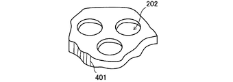
- FIG. 4 and 5 are conceptual diagrams showing the positional relationship between carbon fibers and holes when holes are formed in a carbon / carbon composite using a cloth material.
- FIG. 4 is a conceptual diagram showing a positional relationship when the carbon fiber 401 is located at the center of the formation place of the hole 202.
- FIG. 5 is a conceptual diagram showing the positional relationship when the carbon fiber 401 is located near the end of the formation place of the hole 202.
- the positional relationship of FIG. 4 and FIG. 5 may be obtained by forming a hole without particularly positioning the carbon fiber. .
- the drill bit moves in the circumferential direction of the hole 202 (in the direction of arrow A or arrow A ′ in FIG. 4). That is, the movement direction of the drill bit is perpendicular to the fiber direction of the carbon fiber 401.
- the carbon fibers 401 are cut relatively easily because the strength of the carbon fibers 401 in the direction perpendicular to the fiber direction is weaker than in other directions.
- the drill bit moves in the circumferential direction of the hole 202 (in the direction of arrow B in FIG. 5). That is, the movement direction of the drill bit is parallel to the fiber direction of the carbon fiber 401. Since the strength of the carbon fiber 401 in the direction parallel to the fiber direction is stronger than in other directions, the carbon fiber 401 is not easily cut in this case.
- carbon fibers 401 are knitted vertically and horizontally.
- the direction of movement of the drill bit coincides with the direction parallel to the longitudinal or lateral fibers every 90 °. Therefore, in the processing of the carbon / carbon composite using the cloth material, the positional relationship as shown in FIG. 5 can occur with high frequency.
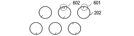
- FIG. 6 is an enlarged top view of the grid 200 after the holes 202 are formed.
- the carbon fiber 401 may remain without being cut during the penetration process.
- a carbon fiber protrusion 601 may be formed on the wall surface of the hole.
- the protruding carbon fiber may be bent along the wall surface of the hole 202 as in the protruding portion 602 of FIG. In such a state, it becomes difficult to remove the protruding carbon fibers.
- the fiber direction of the carbon fiber 401 is oriented in the thickness direction of the carbon / carbon composite.
- the carbon fiber 401 since the drill bit moves perpendicularly to the fiber direction during the penetration process, the carbon fiber 401 is relatively easily cut. Therefore, in this case, the carbon fiber hardly protrudes from the wall surface of the hole 202.
- the carbon fiber fibers are not oriented in the horizontal direction, the effect of reinforcing the rigidity by using the carbon / carbon composite is weakened. Therefore, it is not preferable to set the fiber direction of the carbon fiber in the direction of the plate thickness direction.
- carbon fiber protrusions 601 may be formed on the wall surface of the hole when the hole is processed. .
- the present invention has been made in view of the above-described technical problems, and an object thereof is to provide a grid that is easy to process and in which carbon fiber protrusions are not easily formed on the wall surface of the hole during the processing of the hole. .
- One aspect of the present invention is a plate-like grid having holes, and the grid is made of a carbon / carbon composite containing carbon fibers arranged in a random direction in the plane direction of the grid.
- the holes of the grid are formed so as to cut the carbon fibers.
- FIG. 1 is a structural diagram of an ion beam etching apparatus in which a grid according to an embodiment of the present invention is used. It is a structural diagram of a grid according to an embodiment of the present invention. It is a flowchart which shows the manufacturing method of the grid using a carbon / carbon composite. It is a conceptual diagram which shows the positional relationship when carbon fiber is located in the center of the formation location of a hole. It is a conceptual diagram which shows the positional relationship when carbon fiber is located in the edge part vicinity of the formation location of a hole. It is an upper surface enlarged view of the grid after forming a hole. It is a figure which shows the state which made the fiber direction of the carbon fiber the direction of the plate
- the ion beam etching apparatus 100 includes a plasma generation chamber 102 for generating plasma and a processing chamber 101 for performing an etching process.
- a bell jar (discharge vessel) 104, a gas introduction part 105, an antenna 106, and a Faraday shield 118 are installed as plasma forming means for forming plasma.
- the bell jar 104 is a part of the outer wall of the chamber that defines the discharge space of the plasma generation chamber 102 and keeps the inside in a vacuum.
- the gas introduction unit 105 is a part for introducing a process gas such as argon (Ar) necessary for generating plasma, and is connected to a cylinder (not shown) or the like.
- the antenna 106 is a power application unit composed of conductive wiring or the like, and is used to generate plasma in the bell jar 104.
- the Faraday shield 118 is a metal grid electrode installed on the inner wall surface of the bell jar 104, and has a function of making the high frequency electric field radiated from the antenna uniform.
- a discharge power source 112 that supplies high-frequency power (source power) to the antenna 106, a matching unit 107 provided between the discharge power source 112 and the antenna 106, and an electromagnetic coil that generates a magnetic field inside the bell jar 104. 108 is provided.
- the process gas introduced from the gas introduction unit 105 is ionized, and plasma is formed in the plasma generation chamber 102.
- the processing chamber 101 exhausts the inside of the neutralizer 113 that neutralizes the ion beam, the substrate holder 110 that is a holding unit for holding the substrate 111 that is an object to be processed, the plasma generation chamber 102 and the processing chamber 101. And an exhaust pump 103 for maintaining a vacuum.
- the substrate holder 110 includes various substrate fixing members such as a clamp chuck.
- the substrate holder 110 may include a driving mechanism such as a self-revolving mechanism for irradiating an ion beam incident on the substrate at a predetermined position or angle.
- a grid assembly 109 having holes through which ions are extracted is installed at the boundary between the plasma generation chamber 102 and the processing chamber 101.
- the grid assembly 109 has one or more grids 200.
- the plasma generated in the plasma generation chamber 102 passes through the holes of the grid 200 and is drawn out to the processing chamber 101 and irradiated onto the substrate 111.
- a voltage is applied to the grid 200 by a voltage source (not shown) for ion acceleration or the like.
- a process gas containing an inert gas such as argon (Ar) is introduced from the gas introduction unit 105 into the plasma generation chamber 102.
- high frequency power is applied to the antenna 106 from the discharge power source 112 to ionize the process gas in the plasma generation chamber 102 to generate plasma containing ions.
- Ions contained in the plasma formed in the plasma generation chamber 102 are accelerated by a voltage applied to the grid 200 when passing through holes provided in the grid assembly 109. In this way, an ion beam is drawn from the plasma generation chamber 102 to the processing chamber 101.
- the ion beam is extracted to the processing chamber 101 and then neutralized by the neutralizer 113.
- the neutralized beam is applied to the substrate 111, and the substrate surface is etched.
- each grid 200 has a hole position when viewed from a direction perpendicular to the plane of the grid assembly 109. It is preferable to arrange so that it may overlap. By arranging in this way, the ion beam can be extracted vertically and uniformly with respect to the grid assembly 109.
- an ion beam etching apparatus is exemplified as an apparatus to which the present invention is applied, but the present invention can also be applied to other apparatuses.
- the present invention can be widely applied to ion beam processing apparatuses that generate accelerated particles by extracting ions from plasma, such as an ion implantation apparatus and an ion beam sputtering apparatus. Moreover, even if it is except an ion beam processing apparatus, you may apply to the use using a plate-shaped member which has a some hole and requires intensity
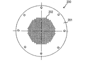
- FIG. 2 is a structural diagram of a grid according to an embodiment of the present invention.
- the grid 200 has a plurality of holes 202 formed on the grid plate 201.
- the grid plate 201 is a disk-shaped member made of carbon / carbon composite.
- the grid plate 201 has a circular shape, but may be appropriately changed according to the shape of the ion source to which the grid 200 is applied.
- the hole 202 is a circular hole formed on the grid plate 201.
- the shape of the hole 202 is not limited to a circle, but may be a shape other than a circle such as a polygon or an ellipse.
- the grid assembly 109 is installed inside an ion beam processing apparatus or the like.
- the grid assembly 109 may be installed horizontally or obliquely in the ion beam processing apparatus.
- the grid 200 constituting the grid assembly 109 may bend by its own weight, and the gap between the holes 202 of each grid 200 may change.
- the gap between the holes 202 of each grid 200 changes, it becomes difficult to extract the ion beam vertically and uniformly. In the present embodiment, such a problem is unlikely to occur because the carbon / carbon composite is strong and lightweight.
- the carbon / carbon composite has a small linear expansion coefficient, the position shift of the hole 202 due to thermal expansion hardly occurs. Furthermore, since carbon / carbon composites are mainly made of carbon, contamination is less likely to be a problem when manufacturing electronic components using an ion beam processing apparatus. From the above viewpoint, it is preferable to use a carbon / carbon composite as the material of the grid plate 201.
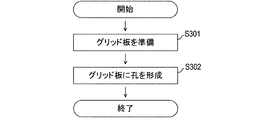
- FIG. 3 is a flowchart showing a method for manufacturing a grid using a carbon / carbon composite.
- a grid plate 201 as a material of the grid 200 is prepared.
- a carbon / carbon composite plate processed to have a predetermined thickness and a predetermined size according to the design of the ion beam etching apparatus 100 is used. Although details will be described later, the carbon / carbon composite used in this step has carbon fibers of a chop material.
- a plurality of holes 202 are formed in the grid plate 201.
- the performance of the ion beam etching apparatus 100 such as the etching rate and the straightness of the beam changes. Therefore, in the processing of the grid 200 for the ion beam processing apparatus, it is required that a large number of holes 202 can be stably formed with a predetermined pitch and dimensions.
- a processing tool that performs cutting by a rotary motion such as a drill or an end mill.
- a carbon / carbon composite is a composite material in which carbon fibers as a reinforcing material are arranged in a carbon matrix (base material) as a support material.
- cloth materials and chop materials can be cited as examples of carbon fibers used in the production of carbon / carbon composites.
- the cloth material is a woven fabric obtained by regularly knitting a bundle of charcoal fiber in the vertical and horizontal directions.
- a carbon / carbon composite using a cloth material is manufactured by impregnating a cloth material containing a carbon such as a thermosetting resin into a cloth material and heating and carbonizing the material. Therefore, a carbon / carbon composite using a cloth material includes carbon fibers extending in two directions, ie, a vertical direction and a horizontal direction perpendicular to each other.
- chopped material is a material shortened by chopping a filamentous carbon fiber to a predetermined length (cut into chopped shapes).
- a carbon / carbon composite using a chop material is manufactured by impregnating a resin into a chop material processed into a mat shape and heat-treating it. At this time, the fibers of the chop material are not aligned in a specific direction, and are randomly or three-dimensionally random with respect to the two-dimensional direction (plane direction). Therefore, the carbon / carbon composite using the chop material includes carbon fibers that are randomly oriented in a plane direction or three-dimensionally.
- random orientation refers to a disordered state in which the carbon fibers as a whole do not have a certain order such as a periodic structure or symmetry in the grid. For example, a region where carbon fibers are partially parallel is included, but the state in which the carbon fiber orientation is not in a certain order as a whole also includes carbon fibers in a “random orientation”. Shall be included.
- a carbon / carbon composite using a chop material is used as a material of the grid 200 instead of the cloth material described above.
- the reason why it is preferable to use the chopping material will be described in comparison with the case where the cloth material is used.
- the carbon fiber may protrude from the hole after processing.
- a grid 200 is applied to the ion beam etching apparatus 100, abnormal discharge starting from the carbon fiber protrusions 601 and 602 may occur during the operation of the ion beam etching apparatus 100.
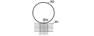
- FIG. 8A is a diagram showing the relationship between the holes formed in the carbon / carbon composite using the cloth material and the arrangement of the carbon fibers.
- FIG. 8B is a diagram showing the relationship between the holes formed in the carbon / carbon composite using the chopping material and the arrangement of the carbon fibers.
- the carbon fiber is depicted only on the lower side of the hole, but in reality, the carbon fiber is similarly disposed around the entire hole.
- the orientations of the carbon fibers 401 are aligned in the vertical direction and the horizontal direction in the figure. Therefore, there is a portion on the circumference of the hole 202 that is difficult to cut the carbon fiber 401 such as the hole lower end 202a. Therefore, the first problem that the carbon fiber protrudes from the wall surface of the hole 202 may occur.
- the orientations of the carbon fibers 401 are random and are not aligned in a specific direction. Therefore, a specific portion on the circumference of the hole 202 is not particularly difficult to cut. Therefore, by using the carbon / carbon composite using the chop material, the protrusion of the carbon fiber on the wall surface of the hole in the processing of the carbon / carbon composite using the cloth material is suppressed.
- FIG. 9 is an enlarged view showing the fiber direction of the cloth material.
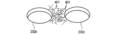
- FIG. 10A is a conceptual diagram when a grid hole is formed using a cloth material
- FIG. 10B is a conceptual diagram when a grid hole is formed using a chop material.
- the orientations of the carbon fibers 401 are aligned in the vertical direction and the horizontal direction in the figure.
- the cloth material has a structure in which a bundle 401a of carbon fibers in the vertical direction and a bundle 401b of carbon fibers in the horizontal direction are woven so as to have a constant interval W. Therefore, when the left hole 202b and the right hole 202c are formed in the grid plate 201 at an interval smaller than the interval W, the vertical carbon fiber bundle 401a between the left hole 202b and the right hole 202c as shown in FIG. The portion where the horizontal carbon fiber 401b is woven may be lost.
- a part of the carbon fibers 401 may be detached and a step 402 may be generated.
- a step 402 is generated in a part of the surface of the grid plate 201 between the left hole 202b and the right hole 202c, and the shape of the hole 202 is changed by the step 402. The problem may occur.
- the horizontal carbon fiber bundle 401b of the first layer remains on the surface, and no step is generated.
- the first layer of horizontal carbon fiber bundles 401b located between the center right side of the left hole 202b and the center left side of the right hole 202c in FIG. It is cut into 401c and 401d.
- the first-layer horizontal carbon fiber bundles 401d cut and isolated by the left hole 202b and the right hole 202c are separated together. Thereby, a bundle 401a of carbon fibers in the vertical direction of the second layer appears on the surface.
- a step 402 is generated between the right circumference of the left hole 202b and the left circumference of the right hole 202c. Due to the step 402, the right side of the center of the left hole 202b and the vicinity of the left side of the center of the right hole 202c are cut and change in shape, resulting in the second problem described above.
- the shape of the grid hole 202 changes, the shape of the ion beam becomes distorted.
- the ion beam shape is distorted, it affects the scattering angle of the ion beam, and processing accuracy (for example, an ion beam etching apparatus has an etching cross-sectional shape, and an ion beam film forming apparatus forms a film on a substrate) This causes a problem that the film thickness distribution) decreases.
- an object to be processed flies and adheres to the grid from the substrate.
- the grid using the cloth material of FIG. 8A there may be a third problem that the processed material attached to the grid peels off the grid and adheres to the substrate.
- the grid using the chopping material of FIG. 8B is used in the ion beam processing apparatus, it is possible to solve the third problem that the object to be processed attached to the grid peels off the grid and adheres to the substrate. It is.
- the uneven pattern formed on the surface of the grid has regularity.
- the force for holding the deposit is weak. Therefore, when the grid using the cloth material of FIG. 8A is used in an ion beam processing apparatus, the object to be processed attached to the grid may peel from the grid and adhere to the substrate, which is a third problem. Cannot be resolved.
- the uneven pattern formed on the surface of the grid has an irregular shape and the ends of the carbon fibers are partially exposed. strong. Therefore, when the grid using the cloth material of FIG. 8B is used in the ion beam processing apparatus, the object to be processed attached to the grid is held by the carbon fiber, so that the third problem can be solved.
- FIG. 11A to FIG. 11D show first micrographs near the holes of the grid using the carbon / carbon composite.
- FIG. 11A is a photomicrograph of a hole in a carbon / carbon composite using a cloth material.
- FIG. 11B is an enlarged view of one of the holes illustrated in FIG. 11A. Referring particularly to FIG. 11B, it can be confirmed that there is a first problem that a plurality of fibrous protrusions are formed from the wall surface of the hole.
- FIG. 11C is a photomicrograph of the vicinity of a grid hole to which a carbon / carbon composite using a chop material is applied.
- FIG. 11D is an enlarged view of one of the holes illustrated in FIG. 11C. Referring specifically to FIG. 11D, it can be confirmed that there are no fibrous protrusions as seen in FIG. 11B. Therefore, it was confirmed that by applying a carbon / carbon composite using a chopping material as a grid plate material, the protrusion of carbon fibers on the wall surface of the hole is suppressed.
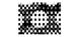
- FIG. 12A is a photomicrograph of a hole in a carbon / carbon composite using a cloth material.
- the carbon fibers of the first layer are cut by the formation of the holes at the center right side of the left hole and the center left side of the right hole, and the carbon fibers are collectively detached.
- the carbon fiber of the 2nd layer has appeared on the surface (in the case of the micrograph of FIG. 12A, the part which looks white in the center part), and on the right circumference of the left hole and the right hole It can be confirmed that there is a second problem that a step occurs on the left circle.
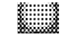
- FIG. 12B is a photomicrograph of the vicinity of a grid hole to which a carbon / carbon composite using a chop material is applied. Referring to FIG. 12B, the second problem described above does not occur, and the hole shape of the left hole and the right hole does not change (in the case of the micrograph of FIG. 12B, the portion that appears white in the center portion) Has not been confirmed).
- a grid for an ion beam etching apparatus using a carbon / carbon composite having high rigidity can be manufactured by using a chopping material as a carbon fiber material. Since the carbon fibers are randomly arranged, it is not necessary to position the hole forming portion with respect to the position of the carbon fibers. Moreover, since the protrusion of the carbon fiber in the hole is suppressed, abnormal discharge that can be generated from the protrusion during the operation of the ion beam etching apparatus 100 is suppressed. Therefore, the process for removing the protruding carbon fibers can be reduced or eliminated. For these reasons, the grid can be manufactured easily and at low cost. Therefore, it is possible to provide a grid having high rigidity and easy processing.
- the grid 200 of the present embodiment may be coated at least partially with a material different from carbon which is the main component of the carbon / carbon composite.
- a material different from carbon which is the main component of the carbon / carbon composite.
- a carbon coating such as metal, vapor-grown carbon, and glassy carbon, or an insulator can be used as the coating material.
- the grid 200 of this embodiment can be used not only for the ion beam etching apparatus shown in FIG. 1 but also for an ion beam processing apparatus such as an ion beam film forming apparatus.
- an ion beam processing apparatus such as an ion beam film forming apparatus.
- a well-known ion beam film-forming apparatus is used.
Landscapes
- Chemical & Material Sciences (AREA)
- Engineering & Computer Science (AREA)
- Analytical Chemistry (AREA)
- Physics & Mathematics (AREA)
- Plasma & Fusion (AREA)
- Combustion & Propulsion (AREA)
- Manufacturing & Machinery (AREA)
- Power Engineering (AREA)
- Optics & Photonics (AREA)
- Plasma Technology (AREA)
- Carbon And Carbon Compounds (AREA)
Abstract
Description
イオンビーム処理装置の一例として、本発明の一実施形態に係るグリッドが用いられるイオンビームエッチング装置の構造図を図1に示す。イオンビームエッチング装置100は、プラズマを発生させるためのプラズマ発生室102とエッチング処理が行われる処理室101とを備える。プラズマ発生室102には、プラズマを形成するためのプラズマ形成手段として、ベルジャ(放電容器)104、ガス導入部105、アンテナ106及びファラデーシールド118が設置されている。ベルジャ104は、プラズマ発生室102の放電空間を画成するとともに内部を真空に保つチャンバ外壁の一部である。ガス導入部105はプラズマの発生に必要なアルゴン(Ar)などのプロセスガスを導入する部分であり、不図示のボンベ等に接続される。アンテナ106は、導電性配線等により構成される電力印加手段であり、ベルジャ104内にプラズマを発生させるために用いられる。ファラデーシールド118は、ベルジャ104の内壁面に設置される金属製の格子状電極であり、アンテナから放射される高周波電場を均一化させる機能を有する。
図11Aから図11Dに、カーボン/カーボンコンポジットを用いたグリッドの孔付近の第1の顕微鏡写真を示す。図11Aは、クロス材を用いたカーボン/カーボンコンポジットの孔の顕微鏡写真である。図11Bは、図11Aに図示された孔の1つを拡大したものである。特に図11Bを参照すると、孔の壁面から複数の繊維状の突起が形成されているという第1の問題点があることが確認できる。
図12A及び図12Bに、カーボン/カーボンコンポジットを用いたグリッドの孔付近の第2の顕微鏡写真を示す。図12Aは、クロス材を用いたカーボン/カーボンコンポジットの孔の顕微鏡写真である。図12Aを参照すると、左側の孔の中央右側と右側の孔の中央左側において、第1層の炭素繊維が、孔の形成によって切断され、炭素繊維がまとまって脱離している。これにより、当該箇所では、第2層の炭素繊維が表面(図12Aの顕微鏡写真の場合は、中央部の白く見える部分)に現れており、左側の孔の右円周上と右側の孔の左円周上に段差が発生するというという第2の問題点があることが確認できる。
本実施形態のグリッド200には、少なくとも一部にカーボン/カーボンコンポジットの主成分である炭素とは異なる材料による被覆が施されていてもよい。例えば金属や気相成長炭素、ガラス状炭素等の炭素コート、または絶縁体を被覆材として用いることができる。孔202の形成後に被覆を行うことにより、炭素繊維の突出をより確実に抑制することができる。
Claims (5)
- 孔を有する板状のグリッドであって、
前記グリッドは、前記グリッドの面方向にランダムな向きに配置された炭素繊維を含むカーボン/カーボンコンポジットを材料とするものであり、
前記グリッドの孔は、前記炭素繊維を切断するように形成されていることを特徴とするグリッド。 - 前記カーボン/カーボンコンポジットに含まれる炭素繊維はチョップド炭素繊維であることを特徴とする請求項1に記載のグリッド。
- 前記グリッドは、カーボン/カーボンコンポジットとは異なる材料により、カーボン/カーボンコンポジットの少なくとも一部が被覆されていることを特徴とする請求項1に記載のグリッド。
- プラズマ発生手段と、
処理室と、
前記プラズマ発生手段で発生されたプラズマから前記処理室にイオンを引き出すための、請求項1に記載のグリッドを含むグリッドアセンブリと
を備えることを特徴とするイオンビーム処理装置。 - 面方向にランダムな向きに配置された炭素繊維を含む、板状のカーボン/カーボンコンポジットを準備する工程と、
回転運動による切削加工を行う加工工具を用いて、前記炭素繊維を切断するように前記カーボン/カーボンコンポジットに孔を形成する工程と
を備えることを特徴とするグリッドの製造方法。
Priority Applications (4)
| Application Number | Priority Date | Filing Date | Title |
|---|---|---|---|
| KR1020167036134A KR101893810B1 (ko) | 2015-03-16 | 2015-11-25 | 그리드 및 그 제조 방법 그리고 이온빔 처리 장치 |
| SG11201610529QA SG11201610529QA (en) | 2015-03-16 | 2015-11-25 | Grid, method of manufacturing the same, and ion beam processing apparatus |
| JP2016508887A JP5970143B1 (ja) | 2015-03-16 | 2015-11-25 | グリッド及びその製造方法並びにイオンビーム処理装置 |
| US15/366,660 US9721747B2 (en) | 2015-03-16 | 2016-12-01 | Grid, method of manufacturing the same, and ion beam processing apparatus |
Applications Claiming Priority (2)
| Application Number | Priority Date | Filing Date | Title |
|---|---|---|---|
| JP2015052363 | 2015-03-16 | ||
| JP2015-052363 | 2015-03-16 |
Related Child Applications (1)
| Application Number | Title | Priority Date | Filing Date |
|---|---|---|---|
| US15/366,660 Continuation US9721747B2 (en) | 2015-03-16 | 2016-12-01 | Grid, method of manufacturing the same, and ion beam processing apparatus |
Publications (1)
| Publication Number | Publication Date |
|---|---|
| WO2016147232A1 true WO2016147232A1 (ja) | 2016-09-22 |
Family
ID=56918553
Family Applications (1)
| Application Number | Title | Priority Date | Filing Date |
|---|---|---|---|
| PCT/JP2015/005851 Ceased WO2016147232A1 (ja) | 2015-03-16 | 2015-11-25 | グリッド及びその製造方法並びにイオンビーム処理装置 |
Country Status (5)
| Country | Link |
|---|---|
| US (1) | US9721747B2 (ja) |
| KR (1) | KR101893810B1 (ja) |
| SG (1) | SG11201610529QA (ja) |
| TW (1) | TWI588860B (ja) |
| WO (1) | WO2016147232A1 (ja) |
Cited By (2)
| Publication number | Priority date | Publication date | Assignee | Title |
|---|---|---|---|---|
| US9721747B2 (en) | 2015-03-16 | 2017-08-01 | Canon Anelva Corporation | Grid, method of manufacturing the same, and ion beam processing apparatus |
| CN115241032A (zh) * | 2021-04-23 | 2022-10-25 | 日新离子机器株式会社 | 离子源 |
Families Citing this family (3)
| Publication number | Priority date | Publication date | Assignee | Title |
|---|---|---|---|---|
| JP6810391B2 (ja) * | 2018-05-18 | 2021-01-06 | 日新イオン機器株式会社 | イオン源 |
| KR102125063B1 (ko) * | 2019-02-22 | 2020-06-19 | 박흥균 | 빔 조절 기능을 갖는 반도체 공정 시스템용 그리드 장치 및, 이를 이용한 반도체 박막 공정 방법 |
| US20230031722A1 (en) * | 2021-07-23 | 2023-02-02 | Taiwan Semiconductor Manufacturing Co., Ltd. | Voltage Control for Etching Systems |
Citations (1)
| Publication number | Priority date | Publication date | Assignee | Title |
|---|---|---|---|---|
| US5548953A (en) * | 1993-02-26 | 1996-08-27 | The Boeing Company | Carbon-carbon grid elements for ion thruster ion optics |
Family Cites Families (20)
| Publication number | Priority date | Publication date | Assignee | Title |
|---|---|---|---|---|
| KR910016054A (ko) | 1990-02-23 | 1991-09-30 | 미다 가쓰시게 | 마이크로 전자 장치용 표면 처리 장치 및 그 방법 |
| US5448883A (en) * | 1993-02-26 | 1995-09-12 | The Boeing Company | Ion thruster with ion optics having carbon-carbon composite elements |
| US5465023A (en) * | 1993-07-01 | 1995-11-07 | The United States Of America As Represented By The Administrator Of The National Aeronautics And Space Administration | Carbon-carbon grid for ion engines |
| US6885010B1 (en) * | 2003-11-12 | 2005-04-26 | Thermo Electron Corporation | Carbon nanotube electron ionization sources |
| US7834530B2 (en) * | 2004-05-27 | 2010-11-16 | California Institute Of Technology | Carbon nanotube high-current-density field emitters |
| US7129513B2 (en) * | 2004-06-02 | 2006-10-31 | Xintek, Inc. | Field emission ion source based on nanostructure-containing material |
| US7034290B2 (en) * | 2004-09-24 | 2006-04-25 | Agilent Technologies, Inc. | Target support with pattern recognition sites |
| US7075067B2 (en) * | 2004-10-15 | 2006-07-11 | Agilent Technologies, Inc. | Ionization chambers for mass spectrometry |
| JP4434963B2 (ja) * | 2005-01-06 | 2010-03-17 | パイオニア株式会社 | 磁気記録装置用磁気ヘッド |
| US7507972B2 (en) * | 2005-10-10 | 2009-03-24 | Owlstone Nanotech, Inc. | Compact ionization source |
| US7750297B1 (en) * | 2007-03-09 | 2010-07-06 | University Of Central Florida Research Foundation, Inc. | Carbon nanotube collimator fabrication and application |
| CN101276724B (zh) * | 2007-03-30 | 2011-06-22 | 北京富纳特创新科技有限公司 | 透射电镜微栅及其制备方法 |
| US8294098B2 (en) * | 2007-03-30 | 2012-10-23 | Tsinghua University | Transmission electron microscope micro-grid |
| CN101848564B (zh) * | 2009-03-27 | 2012-06-20 | 清华大学 | 加热器件 |
| CN101998706B (zh) * | 2009-08-14 | 2015-07-01 | 清华大学 | 碳纳米管织物及应用该碳纳米管织物的发热体 |
| JP2013115012A (ja) * | 2011-11-30 | 2013-06-10 | Ulvac Japan Ltd | 荷電粒子引出照射機構 |
| WO2013099372A1 (ja) * | 2011-12-27 | 2013-07-04 | キヤノンアネルバ株式会社 | 放電容器及びプラズマ処理装置 |
| US9230772B2 (en) * | 2011-12-28 | 2016-01-05 | Schlumberger Technology Corporation | Device and method for ion generation |
| SG11201610529QA (en) | 2015-03-16 | 2017-01-27 | Canon Anelva Corp | Grid, method of manufacturing the same, and ion beam processing apparatus |
| JP6184441B2 (ja) * | 2015-06-01 | 2017-08-23 | キヤノンアネルバ株式会社 | イオンビームエッチング装置、およびイオンビーム発生装置 |
-
2015
- 2015-11-25 SG SG11201610529QA patent/SG11201610529QA/en unknown
- 2015-11-25 KR KR1020167036134A patent/KR101893810B1/ko active Active
- 2015-11-25 WO PCT/JP2015/005851 patent/WO2016147232A1/ja not_active Ceased
-
2016
- 2016-03-02 TW TW105106337A patent/TWI588860B/zh active
- 2016-12-01 US US15/366,660 patent/US9721747B2/en active Active
Patent Citations (1)
| Publication number | Priority date | Publication date | Assignee | Title |
|---|---|---|---|---|
| US5548953A (en) * | 1993-02-26 | 1996-08-27 | The Boeing Company | Carbon-carbon grid elements for ion thruster ion optics |
Cited By (4)
| Publication number | Priority date | Publication date | Assignee | Title |
|---|---|---|---|---|
| US9721747B2 (en) | 2015-03-16 | 2017-08-01 | Canon Anelva Corporation | Grid, method of manufacturing the same, and ion beam processing apparatus |
| CN115241032A (zh) * | 2021-04-23 | 2022-10-25 | 日新离子机器株式会社 | 离子源 |
| JP2022167278A (ja) * | 2021-04-23 | 2022-11-04 | 日新イオン機器株式会社 | イオン源 |
| JP7543970B2 (ja) | 2021-04-23 | 2024-09-03 | 日新イオン機器株式会社 | イオン源 |
Also Published As
| Publication number | Publication date |
|---|---|
| SG11201610529QA (en) | 2017-01-27 |
| US20170084419A1 (en) | 2017-03-23 |
| TW201643926A (zh) | 2016-12-16 |
| KR20170012395A (ko) | 2017-02-02 |
| US9721747B2 (en) | 2017-08-01 |
| TWI588860B (zh) | 2017-06-21 |
| KR101893810B1 (ko) | 2018-09-04 |
Similar Documents
| Publication | Publication Date | Title |
|---|---|---|
| WO2016147232A1 (ja) | グリッド及びその製造方法並びにイオンビーム処理装置 | |
| US12505979B2 (en) | Ion beam processing apparatus, electrode assembly, and method of cleaning electrode assembly | |
| TWI428953B (zh) | 藉由電子迴旋共振使用基本電漿源以處理至少一零件的表面之方法及裝置 | |
| KR101048057B1 (ko) | 플라즈마 잠입 이온을 이용한 가공 장치 및 방법 | |
| JP6220749B2 (ja) | イオンガン及びイオンミリング装置、イオンミリング方法 | |
| JP6539414B2 (ja) | イオン注入器用リペラー、カソード、チャンバーウォール、スリット部材、及びこれを含むイオン発生装置 | |
| CN1871685A (zh) | 具有局部有效电感等离子体耦合的等离子体处理系统 | |
| JP6465892B2 (ja) | 基板処理システム及び基板処理方法 | |
| US20080164427A1 (en) | Ion implanters | |
| JP2008186806A (ja) | イオンビーム装置 | |
| JP2017523562A (ja) | 織目加工された内面を有するイオン注入源 | |
| JP5212820B2 (ja) | 汚染物収集面を備えたイオン注入装置 | |
| JP5970143B1 (ja) | グリッド及びその製造方法並びにイオンビーム処理装置 | |
| JP2013139642A (ja) | スパッタ成膜応用のためのプラズマ処理装置 | |
| JP2009545101A (ja) | プラズマ源 | |
| GB2534021A (en) | Metal coated fibre forming apparatus and method of forming a metal coated fibre | |
| JP2008223112A (ja) | プラズマ処理装置 | |
| JP6509553B2 (ja) | スパッタリング装置 | |
| TWI449077B (zh) | 用以製造工件之方法及離子蝕刻設備 | |
| JP2010153096A (ja) | イオンガン及びイオンビームの引出し方法 | |
| KR102908511B1 (ko) | 하전 입자 제어를 기반으로 한 원자층 식각 장치 및 방법 | |
| JPWO2017221832A1 (ja) | プラズマ源及びプラズマ処理装置 | |
| KR20240022110A (ko) | 고분자 재료의 표면 전기전도도 향상 방법 | |
| KR101368573B1 (ko) | 선형 이온빔 발생장치를 이용한 융복합 표면처리장치 | |
| JP2013173973A (ja) | 成膜装置、および成膜方法 |
Legal Events
| Date | Code | Title | Description |
|---|---|---|---|
| ENP | Entry into the national phase |
Ref document number: 2016508887 Country of ref document: JP Kind code of ref document: A |
|
| 121 | Ep: the epo has been informed by wipo that ep was designated in this application |
Ref document number: 15885330 Country of ref document: EP Kind code of ref document: A1 |
|
| ENP | Entry into the national phase |
Ref document number: 20167036134 Country of ref document: KR Kind code of ref document: A |
|
| WWE | Wipo information: entry into national phase |
Ref document number: 1020167036134 Country of ref document: KR |
|
| NENP | Non-entry into the national phase |
Ref country code: DE |
|
| 122 | Ep: pct application non-entry in european phase |
Ref document number: 15885330 Country of ref document: EP Kind code of ref document: A1 |