WO2016143712A1 - ディスクロータの製造方法 - Google Patents
ディスクロータの製造方法 Download PDFInfo
- Publication number
- WO2016143712A1 WO2016143712A1 PCT/JP2016/056882 JP2016056882W WO2016143712A1 WO 2016143712 A1 WO2016143712 A1 WO 2016143712A1 JP 2016056882 W JP2016056882 W JP 2016056882W WO 2016143712 A1 WO2016143712 A1 WO 2016143712A1
- Authority
- WO
- WIPO (PCT)
- Prior art keywords
- disk rotor
- layer
- oxynitride layer
- graphite
- manufacturing
- Prior art date
- Legal status (The legal status is an assumption and is not a legal conclusion. Google has not performed a legal analysis and makes no representation as to the accuracy of the status listed.)
- Ceased
Links
Images





Classifications
-
- C—CHEMISTRY; METALLURGY
- C23—COATING METALLIC MATERIAL; COATING MATERIAL WITH METALLIC MATERIAL; CHEMICAL SURFACE TREATMENT; DIFFUSION TREATMENT OF METALLIC MATERIAL; COATING BY VACUUM EVAPORATION, BY SPUTTERING, BY ION IMPLANTATION OR BY CHEMICAL VAPOUR DEPOSITION, IN GENERAL; INHIBITING CORROSION OF METALLIC MATERIAL OR INCRUSTATION IN GENERAL
- C23C—COATING METALLIC MATERIAL; COATING MATERIAL WITH METALLIC MATERIAL; SURFACE TREATMENT OF METALLIC MATERIAL BY DIFFUSION INTO THE SURFACE, BY CHEMICAL CONVERSION OR SUBSTITUTION; COATING BY VACUUM EVAPORATION, BY SPUTTERING, BY ION IMPLANTATION OR BY CHEMICAL VAPOUR DEPOSITION, IN GENERAL
- C23C8/00—Solid state diffusion of only non-metal elements into metallic material surfaces; Chemical surface treatment of metallic material by reaction of the surface with a reactive gas, leaving reaction products of surface material in the coating, e.g. conversion coatings, passivation of metals
- C23C8/02—Pretreatment of the material to be coated
-
- C—CHEMISTRY; METALLURGY
- C23—COATING METALLIC MATERIAL; COATING MATERIAL WITH METALLIC MATERIAL; CHEMICAL SURFACE TREATMENT; DIFFUSION TREATMENT OF METALLIC MATERIAL; COATING BY VACUUM EVAPORATION, BY SPUTTERING, BY ION IMPLANTATION OR BY CHEMICAL VAPOUR DEPOSITION, IN GENERAL; INHIBITING CORROSION OF METALLIC MATERIAL OR INCRUSTATION IN GENERAL
- C23C—COATING METALLIC MATERIAL; COATING MATERIAL WITH METALLIC MATERIAL; SURFACE TREATMENT OF METALLIC MATERIAL BY DIFFUSION INTO THE SURFACE, BY CHEMICAL CONVERSION OR SUBSTITUTION; COATING BY VACUUM EVAPORATION, BY SPUTTERING, BY ION IMPLANTATION OR BY CHEMICAL VAPOUR DEPOSITION, IN GENERAL
- C23C10/00—Solid state diffusion of only metal elements or silicon into metallic material surfaces
- C23C10/60—After-treatment
-
- C—CHEMISTRY; METALLURGY
- C23—COATING METALLIC MATERIAL; COATING MATERIAL WITH METALLIC MATERIAL; CHEMICAL SURFACE TREATMENT; DIFFUSION TREATMENT OF METALLIC MATERIAL; COATING BY VACUUM EVAPORATION, BY SPUTTERING, BY ION IMPLANTATION OR BY CHEMICAL VAPOUR DEPOSITION, IN GENERAL; INHIBITING CORROSION OF METALLIC MATERIAL OR INCRUSTATION IN GENERAL
- C23C—COATING METALLIC MATERIAL; COATING MATERIAL WITH METALLIC MATERIAL; SURFACE TREATMENT OF METALLIC MATERIAL BY DIFFUSION INTO THE SURFACE, BY CHEMICAL CONVERSION OR SUBSTITUTION; COATING BY VACUUM EVAPORATION, BY SPUTTERING, BY ION IMPLANTATION OR BY CHEMICAL VAPOUR DEPOSITION, IN GENERAL
- C23C8/00—Solid state diffusion of only non-metal elements into metallic material surfaces; Chemical surface treatment of metallic material by reaction of the surface with a reactive gas, leaving reaction products of surface material in the coating, e.g. conversion coatings, passivation of metals
- C23C8/06—Solid state diffusion of only non-metal elements into metallic material surfaces; Chemical surface treatment of metallic material by reaction of the surface with a reactive gas, leaving reaction products of surface material in the coating, e.g. conversion coatings, passivation of metals using gases
- C23C8/08—Solid state diffusion of only non-metal elements into metallic material surfaces; Chemical surface treatment of metallic material by reaction of the surface with a reactive gas, leaving reaction products of surface material in the coating, e.g. conversion coatings, passivation of metals using gases only one element being applied
- C23C8/24—Nitriding
- C23C8/26—Nitriding of ferrous surfaces
-
- C—CHEMISTRY; METALLURGY
- C23—COATING METALLIC MATERIAL; COATING MATERIAL WITH METALLIC MATERIAL; CHEMICAL SURFACE TREATMENT; DIFFUSION TREATMENT OF METALLIC MATERIAL; COATING BY VACUUM EVAPORATION, BY SPUTTERING, BY ION IMPLANTATION OR BY CHEMICAL VAPOUR DEPOSITION, IN GENERAL; INHIBITING CORROSION OF METALLIC MATERIAL OR INCRUSTATION IN GENERAL
- C23C—COATING METALLIC MATERIAL; COATING MATERIAL WITH METALLIC MATERIAL; SURFACE TREATMENT OF METALLIC MATERIAL BY DIFFUSION INTO THE SURFACE, BY CHEMICAL CONVERSION OR SUBSTITUTION; COATING BY VACUUM EVAPORATION, BY SPUTTERING, BY ION IMPLANTATION OR BY CHEMICAL VAPOUR DEPOSITION, IN GENERAL
- C23C8/00—Solid state diffusion of only non-metal elements into metallic material surfaces; Chemical surface treatment of metallic material by reaction of the surface with a reactive gas, leaving reaction products of surface material in the coating, e.g. conversion coatings, passivation of metals
- C23C8/06—Solid state diffusion of only non-metal elements into metallic material surfaces; Chemical surface treatment of metallic material by reaction of the surface with a reactive gas, leaving reaction products of surface material in the coating, e.g. conversion coatings, passivation of metals using gases
- C23C8/28—Solid state diffusion of only non-metal elements into metallic material surfaces; Chemical surface treatment of metallic material by reaction of the surface with a reactive gas, leaving reaction products of surface material in the coating, e.g. conversion coatings, passivation of metals using gases more than one element being applied in one step
- C23C8/30—Carbo-nitriding
- C23C8/32—Carbo-nitriding of ferrous surfaces
-
- C—CHEMISTRY; METALLURGY
- C23—COATING METALLIC MATERIAL; COATING MATERIAL WITH METALLIC MATERIAL; CHEMICAL SURFACE TREATMENT; DIFFUSION TREATMENT OF METALLIC MATERIAL; COATING BY VACUUM EVAPORATION, BY SPUTTERING, BY ION IMPLANTATION OR BY CHEMICAL VAPOUR DEPOSITION, IN GENERAL; INHIBITING CORROSION OF METALLIC MATERIAL OR INCRUSTATION IN GENERAL
- C23G—CLEANING OR DE-GREASING OF METALLIC MATERIAL BY CHEMICAL METHODS OTHER THAN ELECTROLYSIS
- C23G1/00—Cleaning or pickling metallic material with solutions or molten salts
- C23G1/28—Cleaning or pickling metallic material with solutions or molten salts with molten salts
- C23G1/32—Heavy metals
-
- F—MECHANICAL ENGINEERING; LIGHTING; HEATING; WEAPONS; BLASTING
- F16—ENGINEERING ELEMENTS AND UNITS; GENERAL MEASURES FOR PRODUCING AND MAINTAINING EFFECTIVE FUNCTIONING OF MACHINES OR INSTALLATIONS; THERMAL INSULATION IN GENERAL
- F16D—COUPLINGS FOR TRANSMITTING ROTATION; CLUTCHES; BRAKES
- F16D65/00—Parts or details
- F16D65/02—Braking members; Mounting thereof
- F16D65/12—Discs; Drums for disc brakes
Definitions
- the present invention relates to a method for manufacturing a disc rotor used for a vehicle disc brake.
- a disk rotor (specifically, a casting material thereof) is formed by a casting method, and cast iron constituting the disk rotor contains graphite. And when using a disk rotor, it is known that a water
- a de-graphite treatment is performed on a material of a disk rotor according to a chemical cleaning method by immersion in molten salt. Through this degraphitization treatment, the graphite on the material surface is removed.
- the material of the disk rotor is subjected to gas soft nitriding according to a known gas soft nitriding method.
- gas soft nitriding treatment a nitride layer (compound layer) and an oxynitride layer (oxynitride layer) are sequentially formed on the surface of the material, and the compound layer and the oxynitride layer form the surface and surface layer of the material. The remaining graphite is coated.
- An object of the present invention is to provide a method of manufacturing a disk rotor that can provide high corrosion resistance.
- a disk rotor manufacturing method includes subjecting a disk rotor material to a de-graphite treatment according to a chemical cleaning method using molten salt immersion to remove graphite on the surface layer of the material, and softening the material.
- Nitriding treatment is performed to sequentially laminate a compound layer and an oxynitride layer on the surface of the same material, and the material on which the compound layer and the oxynitride layer are formed has a temperature of 300 to 500 degrees Celsius.
- Applying an oxidation bath treatment in which the material is immersed in a heated oxidation bath containing nitrate for 10 to 60 minutes.
- the surface of the material is covered with the compound layer and the oxynitride layer through the soft nitriding treatment. Therefore, it is possible to prevent moisture from penetrating into the graphite inside the disk rotor and to obtain an antirust effect.
- a dense oxide layer can be formed on the surface of the oxynitride layer formed by the soft nitriding treatment through the oxidation bath treatment. For this reason, the dense oxide layer can close the holes on the surface of the oxynitride layer and the holes on the inside thereof, and the penetration of moisture into the disk rotor can be suitably suppressed. Therefore, according to the manufacturing method, a disk rotor having high corrosion resistance can be manufactured.
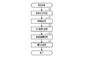
- the flowchart which shows the execution procedure of the manufacturing method of the embodiment.
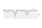
- the schematic diagram which shows typically the formation aspect of the oxide layer of the disc rotor of the embodiment.
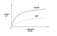
- the graph which shows the relationship between the presence or absence of execution of de-graphite processing, the processing time of gas soft nitriding, and the thickness of a compound layer.
- tissue photograph of the disk rotor of a 2nd comparative example (magnification 3000 times).
- the disk rotor 20 includes a bearing portion 21 that is a portion fixed to a vehicle and two sliding plates 22 and 23, and the bearing portion 21 and the sliding plates 22 and 23 It is integrally formed.
- the bearing portion 21 includes a cylindrical peripheral wall portion 21A and an annular lid portion 21B that covers one opening of the cylindrical shape.
- Each of the sliding plates 22 and 23 has an annular shape extending along the same central axis L as the peripheral wall portion 21A, and is arranged at an interval. Between the sliding plates 22 and 23, a plurality of ribs 24 having a radially extending shape around the central axis L are provided.
- the manufacturing method of the present embodiment is not limited to the above-described ventilated disk rotor 20, but can be applied to a solid disk rotor, a two-piece disk rotor, a drum-in-hat disk rotor, and the like. It is.
- the material M0 of the disk rotor 20 is formed (pre-process S0).
- the material M0 is formed by a procedure in which a casting material of the disk rotor 20 is molded by a casting method and the casting material is processed into a predetermined shape by machining.
- the raw material M0 is subjected to de-graphite treatment according to a chemical cleaning method using molten salt immersion (first step S1).
- a de-graphite treatment the material M0 is immersed in a salt bath (a tank containing molten salt) and subjected to an oxidation reaction by electrolysis to remove graphite (specifically, carbon) from the material M0.
- a process for performing (so-called Colleen process) is executed.
- the temperature of the salt bath is set to 400 to 500 degrees Celsius (in this embodiment, 450 degrees Celsius), and the treatment time is set to 60 to 120 minutes (in this embodiment, 60 minutes).
- the alkaline salt of the US KOLENE company is used, for example.
- the material M1 is subjected to gas soft nitriding (second step S2).
- gas soft nitriding treatment a reaction gas based on nitrogen and mixed with ammonia or carbon dioxide is used, and the reaction gas temperature is 550 to 650 degrees Celsius (in this embodiment, 580 degrees Celsius).
- the processing time is set to 30 minutes to 240 minutes (in this embodiment, 120 minutes).
- a nitride layer (compound layer) having a thickness of 5 ⁇ m to 50 ⁇ m is formed on the surface of the material M1, and further, an oxynitride having a thickness of 1 ⁇ m to 10 ⁇ m is formed on the surface of the compound layer.
- An object layer oxynitride layer
- the material M2 in a state where the compound layer and the oxynitride layer are formed on the surface of the material M1 is obtained.
- the surface roughness adjustment process is performed (third step S3).
- the average particle diameter of the glass beads is set to 50 ⁇ m to 400 ⁇ m (75 ⁇ m in this embodiment)
- the injection pressure is set to 1 kg pressure to 4 kg pressure (2 kg pressure in this embodiment)
- the injection is performed.
- the time is set to 180 seconds or less (90 seconds in this embodiment).
- the material M3 is subjected to an oxidation bath treatment (fourth step S4).
- the oxidation bath treatment is performed such that the material M3 is immersed in an oxidation bath containing nitrate for a predetermined time and then cooled with water.
- the temperature of the oxidation bath is set to 300 to 500 degrees Celsius (in this embodiment, 470 degrees Celsius), and the treatment time is set to 10 to 60 minutes (in this embodiment, 20 minutes).
- a dense oxide layer (oxide layer) having a thickness of several micrometers is formed on the surface of the material M3.
- the disk rotor 20 in a state in which the compound layer, the oxynitride layer, and the oxide layer are formed on the surface of the material M0 in order from the lower layer side is obtained.
- FIG. 4 show scanning electron micrographs obtained by photographing the cross-sectional structure of the disk rotor 20. Note that the cross-sectional structure photograph shown in FIG. 4 is a photograph with a higher magnification than the cross-sectional structure photograph shown in FIG.
- the graphite that causes rust is removed from the surface layer of the material M1 of the disk rotor 20 through the degraphitization process in the first step.
- the surface of the material M1 from which the graphite has been removed from the surface layer is covered with the compound layer 25 and the oxynitride layer 26 through the gas soft nitriding process in the second step. For this reason, when the disk rotor 20 is used, it is possible to prevent moisture from penetrating into the graphite inside the disk rotor 20 and to obtain an antirust effect.
- FIG. 5, FIG. 6 and FIG. 7 show scanning electron micrographs of the disc rotor of the first comparative example manufactured by omitting the fourth step (oxidation bath treatment) of this embodiment.
- 5 and 6 are images obtained by photographing the cross-sectional structure of the disk rotor
- FIG. 7 is an image obtained by photographing the surface of the disk rotor.
- the cross-sectional structure photograph shown in FIG. 6 shows a photograph at a higher magnification than the cross-sectional structure photograph shown in FIG.
- the compound layer 35 and the oxynitride layer 36 are formed on the surface of the material M1, but the oxide layer (the oxide layer of FIG. 4). 27), the surface of the disk rotor 30 is constituted by the oxynitride layer 36. As apparent from FIGS. 6 and 7, the oxynitride layer 36 is porous. For this reason, in the disk rotor 30 of the first comparative example, there is a possibility that moisture enters the inside of the disk rotor 30 from the outside through the hole of the oxynitride layer 36. And when this moisture reaches
- the oxynitride layer 26 is subjected to the surface roughness adjusting process in the third step.
- the surface roughness of the oxynitride layer 26 is adjusted, and further, an oxide layer 27 is formed on the surface of the oxynitride layer 26 through an oxidation bath treatment in the fourth step.
- the oxide layer 27 is a dense layer although it is thinner than the oxynitride layer 26.
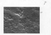
- FIG. 8 schematically shows how the oxide layer 27 is formed on the surface of the oxynitride layer 26, and FIG. 9 shows a photograph of the surface structure obtained by photographing the surface of the disk rotor 20.
- the surface of the oxynitride layer 26 (specifically, the surface of the oxynitride layer 26 facing the oxide layer 27) is formed by the oxide layer 27 formed on the surface of the disk rotor 20.
- the internal holes are narrowed or blocked. Therefore, such an oxide layer 27 can suitably suppress the intrusion of moisture into the oxynitride layer 26, and consequently the intrusion of moisture into the disc rotor 20, and the corrosion resistance of the disc rotor 20 is improved.
- the opposing surfaces and outer peripheral surfaces of the two sliding plates 22 and 23, the ribs 24 and the like may be rusted and chipped, so that the thickness of each part is set to be thick to ensure strength.
- the disk rotor 20 of this embodiment since the generation of rust is suppressed by the oxide layer 27 formed through the oxidation bath process, it is not necessary to anticipate the chipping of each part due to the rust generation, and the thickness of each part is reduced. Thus, the weight can be reduced.
- FIG. 10 shows the relationship between the presence / absence of degraphite treatment, the gas soft nitriding treatment time, and the thickness of the compound layer.
- the manufacturing method shown by a solid line in the drawing
- the degraphitization treatment is performed before the gas soft nitriding treatment
- the thick compound layer 25 can be formed on the surface of the material M1 in the gas soft nitriding treatment. Therefore, according to the manufacturing method of this embodiment, compared with the manufacturing method of a comparative example, the layer which covers the surface of the raw material M1 can be thickened, and the corrosion resistance performance of the disk rotor 20 can be improved.
- the material M1 is formed in a shorter processing time in the gas soft nitriding process than in the manufacturing method of the comparative example indicated by the alternate long and short dash line.
- a thick compound layer 25 can be formed on the surface. Therefore, according to the manufacturing method of this embodiment, the processing time of gas soft nitriding can be shortened compared with the manufacturing method of a comparative example.
- the compound layer 25 can be formed thick in a short processing time because the surface of the material M1 is activated by performing the degraphitization process, and then on the surface of the material M1 when performing the gas soft nitriding process. It is thought that this is because the nitride easily adheres.
- FIG. 11 and 12 are images obtained by photographing the cross-sectional structure of the disk rotor
- FIG. 13 is an image obtained by photographing the surface of the disk rotor.
- the cross-sectional structure photograph shown in FIG. 12 shows a photograph at a higher magnification than the cross-sectional structure photograph shown in FIG.
- the black dyeing process is performed such that the disk rotor material is immersed in an alkaline bath containing caustic soda for a predetermined time.
- the temperature of the alkaline bath is set to 125 to 140 degrees Celsius, and the processing time is set to 10 to 20 minutes.
- an oxide layer (oxide layer 47) having iron oxide as a main component with a thickness of several ⁇ m is formed on the surface thereof through the black dyeing process. ) Is formed. Thereby, the disk rotor 40 in a state in which the compound layer 45, the oxynitride layer 46, and the oxide layer 47 are formed on the surface of the material M1 in order from the lower layer side is obtained.
- the oxide layer 47 of the disk rotor 40 of the second comparative example is rougher than the oxide layer 27 (see FIG. 4) of the disk rotor 20 of the present embodiment.
- oxide crystals partially protrude from the surface or cracks are present. Therefore, it can be said that the disk rotor 40 of the second comparative example has a structure in which voids (oxide gaps) are easily formed inside the oxide layer 47.
- the oxynitride layer 46 of the disk rotor 40 of the second comparative example is porous, the disk rotor 40 is interposed via the gap of the oxide layer 47, the surface holes of the oxynitride layer 46, and the internal holes. It is a structure in which moisture easily penetrates into the interior.
- a dense oxide layer 27 is formed on the surface, and holes on the surface of the oxynitride layer 26 and internal holes are formed. Since it is blocked, the intrusion of moisture into the disk rotor 20 is suitably suppressed, and the corrosion resistance of the disk rotor 20 is improved.
- the disk rotor 20 of the present embodiment is compared with the disk rotor 30 of the first comparative example (see FIG. 6) and the disk rotor 40 of the second comparative example (see FIG. 12).
- the oxynitride layer 26 has a dense structure with small internal holes. The reason why the oxynitride layer 26 becomes dense may be as follows.
- an oxidation bath process is performed.
- This oxidation bath process is performed in a temperature range (400 degrees Celsius or higher) in which oxygen easily diffuses in the disk rotor 20. Therefore, during the execution of the oxidation bath process, part of oxygen in the oxide layer 27 formed in the process diffuses and penetrates into the oxynitride layer 26 constituting the lower layer. As a result, the holes in the oxynitride layer 26 are narrowed, and the oxynitride layer 26 has a dense structure.
- the oxidation bath process is not performed after the formation of the oxynitride layer 46, but the black dyeing process is performed. Therefore, the disk rotor 40 having the oxynitride layer 46 is heated. Become so.
- the black dyeing process has a lower temperature range than the oxidation bath process, and the diffusion and penetration of oxygen in the disk rotor 40 hardly occurs. Therefore, although the disk rotor 40 having the oxynitride layer 46 is heated during the black dyeing process, the effect that the oxynitride layer 46 changes to a dense structure is hardly obtained.
- the oxidation bath process and the black dyeing process are not performed after the oxynitride layer 36 is formed, so that the oxynitride layer 36 formed through the gas soft nitridation process changes to a dense structure. The effect of doing is not obtained.
- the surface oxynitride layer 26 and the internal holes become smaller and the oxynitride layer 26 changes to a dense structure. Becomes difficult to penetrate, and the rust prevention effect is improved.
- the disk rotor 20 is manufactured through de-graphite treatment, gas soft nitriding treatment, and oxidation bath treatment.
- the oxide layer 27 formed through the oxidation bath treatment suitably suppresses the intrusion of moisture into the oxynitride layer 26, and consequently the intrusion of moisture into the disc rotor 20, so that the disk with high corrosion resistance is provided.
- the rotor 20 can be manufactured.
- the above embodiment may be modified as follows.
- the material of the disc rotor 20 is not limited to being formed by a casting method, and can be formed by an arbitrary forming method. In short, any forming method that can appropriately form a material made of an iron-based metal material containing graphite may be used.
- the surface roughness adjusting process is a polishing process that does not unnecessarily scrape the oxynitride layer 26
- any process may be employed without being limited to the process according to the bead shot method. If the surface roughness of the oxynitride layer 26 formed through the gas soft nitriding process is moderately fine, the surface roughness adjusting process may be omitted.
- salt bath soft nitriding may be performed instead of performing gas soft nitriding.
Landscapes
- Chemical & Material Sciences (AREA)
- Engineering & Computer Science (AREA)
- Mechanical Engineering (AREA)
- Materials Engineering (AREA)
- Chemical Kinetics & Catalysis (AREA)
- Metallurgy (AREA)
- Organic Chemistry (AREA)
- General Engineering & Computer Science (AREA)
- General Chemical & Material Sciences (AREA)
- Braking Arrangements (AREA)
- Solid-Phase Diffusion Into Metallic Material Surfaces (AREA)
- Other Surface Treatments For Metallic Materials (AREA)
- Cleaning And De-Greasing Of Metallic Materials By Chemical Methods (AREA)
Abstract
ディスクロータの製造方法は、ディスクロータの素材に溶融塩浸漬による化学洗浄法に従って脱黒鉛処理を施して、同素材の表層の黒鉛を除去することと、素材に軟窒化処理を施して、同素材の表面に化合物層および酸窒化層を順に積層して形成することと、化合物層および酸窒化層が形成された素材に、摂氏300度~500度に加温した硝酸塩を含む酸化浴に10分間~60分間にわたり素材を浸漬する酸化浴処理を施すことと、を含む。
Description
本発明は、車両用ディスクブレーキに使用するディスクロータの製造方法に関する。
自動車などの車両に搭載されるブレーキ装置としては、ディスクロータを備えたディスクブレーキが多用されている。ディスクロータ(詳しくは、その鋳物素材)は鋳造法により形成されており、同ディスクロータを構成する鋳鉄は黒鉛を含有している。そして、ディスクロータの使用に際して、その表面付近の黒鉛に水分が浸透することが、錆の発生原因になることが知られている。
従来、ディスクロータの耐食性能を高くするために、ディスクロータの表層付近の黒鉛を除去したうえで、表面を覆う保護層を形成することが提案されている(特許文献1参照)。
特許文献1に記載の製造方法では、先ず、ディスクロータの素材に、溶融塩浸漬による化学的洗浄法に従って脱黒鉛処理が施される。この脱黒鉛処理を通じて、素材表面の黒鉛が除去される。次に、ディスクロータの素材に、公知のガス軟窒化法に従ってガス軟窒化処理が施される。このガス軟窒化処理によって、素材表面に窒化物の層(化合物層)と酸窒化物の層(酸窒化層)とが順に形成され、それら化合物層および酸窒化層によって上記素材の表面や表層に残った黒鉛が被覆される。
特許文献1に記載の製造方法によってディスクロータを製造することにより、ある程度の防錆効果が得られるようになり、ディスクロータの耐食性能が向上するようになる。ただし、ガス軟窒化処理によって形成される酸窒化層は多孔質状であるため、同酸窒化層の表面の孔や内部の孔を介してディスクロータの内部に水分が侵入する可能性は残る。そして、そのようにして内部に侵入した水分がディスクロータ内の黒鉛に到達して浸透するようなことがあると、これが錆の発生原因になるおそれがある。この点において、特許文献1に記載の製造方法は、改善の余地がある。
本発明の目的は、高い耐食性能が得られるディスクロータの製造方法を提供することにある。
上記課題を達成するためのディスクロータの製造方法は、ディスクロータの素材に溶融塩浸漬による化学洗浄法に従って脱黒鉛処理を施して、同素材の表層の黒鉛を除去することと、前記素材に軟窒化処理を施して、同素材の表面に化合物層および酸窒化層を順に積層して形成することと、前記化合物層および前記酸窒化層が形成された前記素材に、摂氏300度~500度に加温した硝酸塩を含む酸化浴に10分間~60分間にわたり前記素材を浸漬する酸化浴処理を施すことと、を含んでいる。
上記製造方法では、脱黒鉛処理を通じて素材表層の黒鉛が除去された後に、軟窒化処理を通じて素材表面が化合物層と酸窒化層とによって覆われる。そのため、ディスクロータ内部の黒鉛に水分が浸透することが抑えられ、防錆効果が得られる。しかも、上記製造方法によれば、軟窒化処理によって形成された酸窒化層の表面に、酸化浴処理を通じて緻密な酸化物層を形成することができる。そのため、この緻密な酸化物層によって、酸窒化層の表面の孔や内部の孔を塞ぐことが可能になり、ディスクロータ内部への水分の侵入が好適に抑えられるようになる。したがって上記製造方法によれば、高い耐食性能のディスクロータを製造することができるようになる。
以下、ディスクロータの製造方法の一実施形態について説明する。
ここでは先ず、本実施形態の製造方法が適用されるディスクロータの構造について説明する。
ここでは先ず、本実施形態の製造方法が適用されるディスクロータの構造について説明する。
図1に示すように、ディスクロータ20は車両に固定される部分である軸受部21と2枚の摺動プレート22,23とを備えており、それら軸受部21および摺動プレート22,23が一体に形成されている。軸受部21は、円筒形状の周壁部21Aと、同円筒形状の一方の開口を覆う円環形状の蓋部21Bとを有している。各摺動プレート22,23は、上記周壁部21Aと同一の中心軸Lで伸びる円環形状であり、間隔をおいて配置されている。それら摺動プレート22,23の間には、中心軸Lを中心とする放射状に延びる形状のリブ24が複数設けられている。なお、本実施形態の製造方法は、上述したベンチレーテッド型のディスクロータ20に限らず、ソリッド型のディスクロータや、2ピース型のディスクロータ、ドラムインハット型のディスクロータなどにも適用可能である。
次に、ディスクロータ20の製造方法について、図2を参照しつつ説明する。
図2に示すように、ディスクロータ20の製造に際しては先ず、ディスクロータ20の素材M0が形成される(前工程S0)。この素材M0は、鋳造法によってディスクロータ20の鋳物素材を成型するとともに、この鋳物素材を機械加工によって所定の形状に加工するといった手順で形成される。
図2に示すように、ディスクロータ20の製造に際しては先ず、ディスクロータ20の素材M0が形成される(前工程S0)。この素材M0は、鋳造法によってディスクロータ20の鋳物素材を成型するとともに、この鋳物素材を機械加工によって所定の形状に加工するといった手順で形成される。
次に、素材M0に、溶融塩浸漬による化学洗浄法に従って脱黒鉛処理が施される(第1工程S1)。この脱黒鉛処理としては、塩浴(溶融塩が収容された槽)の中に素材M0を浸漬し、電気分解によって酸化反応を行わせて、素材M0からの黒鉛(詳しくは、炭素)の除去を行う処理(いわゆるコリーン処理)が実行される。脱黒鉛処理では、塩浴の温度が摂氏400度~500度(本実施形態では、摂氏450度)に設定され、処理時間が60分~120分(本実施形態では、60分)に設定される。また、上記溶融塩としては、例えば米国コリーン(KOLENE)社のアルカリ系ソルトが用いられる。こうした脱黒鉛処理を通じて、表層の黒鉛が除去された状態の素材M1が得られる。
その後、素材M1に、ガス軟窒化処理が施される(第2工程S2)。このガス軟窒化処理では、反応ガスとして、窒素をベースとしたものにアンモニアや二酸化炭素を混合したものが使用され、反応ガスの温度が摂氏550度~650度(本実施形態では、摂氏580度)に設定され、処理時間が30分~240分(本実施形態では、120分)に設定される。このガス軟窒化処理を通じて、素材M1の表面には厚さが5μm~50μmの窒化物の層(化合物層)が形成され、さらには同化合物層の表面には厚さが1μm~10μmの酸窒化物の層(酸窒化層)が形成される。これにより、素材M1の表面に化合物層と酸窒化層とが形成された状態の素材M2が得られる。
次に、素材M2の表面(詳しくは、表層を構成する酸窒化層の表面)に、ビーズ状ガラスの粒(ガラスビーズ)を高速で吹き付けることによって表面を滑らかにする方法(いわゆるビーズショット法)に従って面粗度調整処理が施される(第3工程S3)。この面粗度調整処理では、ガラスビーズの平均粒径が50μm~400μm(本実施形態では75μm)に設定され、噴射圧力が1kg圧~4kg圧(本実施形態では2kg圧)に設定され、噴射時間が180秒以下(本実施形態では90秒)に設定される。こうした面粗度調整処理を通じて、酸窒化層の表面粗さが適度に細かくなった状態の素材M3が得られる。
その後、素材M3に酸化浴処理が施される(第4工程S4)。酸化浴処理は、硝酸塩を含む酸化浴に素材M3を所定時間にわたって浸漬した後に、水冷するといったように実行される。この酸化浴処理では、酸化浴の温度が摂氏300度~500度(本実施形態では、摂氏470度)に設定され、処理時間が10分~60分(本実施形態では20分)に設定される。こうした酸化浴処理を通じて、素材M3の表面に厚さが数μmの緻密な酸化物(酸化鉄を主成分とする)の層(酸化物層)が形成される。これにより、前記素材M0の表面に、下層側から順に、化合物層、酸窒化層、および酸化物層が形成された状態のディスクロータ20が得られる。
以下、このようにしてディスクロータ20を製造することによる作用について説明する。
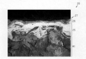
図3および図4に、ディスクロータ20の断面組織を撮影した走査型電子顕微鏡写真を示す。なお、図4に示す断面組織写真は、図3に示す断面組織写真よりも高倍率の写真を示している。
図3および図4に、ディスクロータ20の断面組織を撮影した走査型電子顕微鏡写真を示す。なお、図4に示す断面組織写真は、図3に示す断面組織写真よりも高倍率の写真を示している。
図3および図4に示すように、本実施形態では、第1工程における脱黒鉛処理を通じて、ディスクロータ20の素材M1の表層から、錆発生の原因になる黒鉛が除去される。しかも、そのようにして表層から黒鉛が除去された素材M1の表面が、第2工程におけるガス軟窒化処理を通じて、化合物層25と酸窒化層26とによって覆われるようになる。そのため、ディスクロータ20の使用に際して同ディスクロータ20の内部の黒鉛に水分が浸透することが抑えられて、防錆効果が得られるようになる。
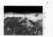
図5、図6および図7に、本実施形態の第4工程(酸化浴処理)を省略して製造した第1比較例のディスクロータを撮影した走査型電子顕微鏡写真を示す。なお、図5および図6はディスクロータの断面組織を撮影した画像であり、図7はディスクロータの表面を撮影した画像である。また、図6に示す断面組織写真は、図5に示す断面組織写真よりも高倍率の写真を示している。
図5および図6に示すように、第1比較例のディスクロータ30では、素材M1の表面に化合物層35と酸窒化層36とが形成されるものの、酸化物層(図4の酸化物層27を参照)が形成されないため、同ディスクロータ30の表面が酸窒化層36によって構成されている。この酸窒化層36は、図6および図7から明らかなように、多孔質状である。そのため、第1比較例のディスクロータ30では、酸窒化層36の孔を介して同ディスクロータ30の外部から内部に水分が侵入する可能性が残る。そして、この水分が、酸窒化層36や化合物層35、並びに素材M1の表層内部に残った黒鉛に到達して浸透するようなことがあると、これが錆発生の原因になるおそれがある。
本実施形態では、図3および図4に示すように、素材M1の表面に化合物層25と酸窒化層26とが形成された後に、第3工程における面粗度調整処理を通じて同酸窒化層26の表面粗さが調節され、さらには、この酸窒化層26の表面に、第4工程における酸化浴処理を通じて酸化物層27が形成される。この酸化物層27は、酸窒化層26と比較して、薄いとはいえ緻密な層である。
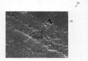
図8に酸窒化層26の表面における酸化物層27の形成態様を模式的に示し、図9にディスクロータ20の表面を撮影した表面組織写真を示す。
図8および図9に示すように、ディスクロータ20の表面に形成された酸化物層27によって、同酸窒化層26の表面(詳しくは、酸化物層27と対向する酸窒化層26の面)の孔や内部の孔が狭められたり塞がれたりするようになる。したがって、こうした酸化物層27により、酸窒化層26内部への水分の侵入、ひいてはディスクロータ20内部への水分の侵入が好適に抑えられるようになり、同ディスクロータ20の耐食性能が高くなる。
図8および図9に示すように、ディスクロータ20の表面に形成された酸化物層27によって、同酸窒化層26の表面(詳しくは、酸化物層27と対向する酸窒化層26の面)の孔や内部の孔が狭められたり塞がれたりするようになる。したがって、こうした酸化物層27により、酸窒化層26内部への水分の侵入、ひいてはディスクロータ20内部への水分の侵入が好適に抑えられるようになり、同ディスクロータ20の耐食性能が高くなる。
通常、ディスクロータ20では、2枚の摺動プレート22,23の対向面や外周面、リブ24等が錆びて欠けることがあるため、強度確保のために各部の肉厚が厚く設定されている。本実施形態のディスクロータ20によれば、酸化浴処理を通じて形成される酸化物層27によって錆の発生が抑えられるため、錆発生による各部の欠けを見込む必要が無くなって、各部の肉厚を薄く形成することが可能になり、その分だけ軽量化を図ることができる。
図10に、脱黒鉛処理の実行の有無とガス軟窒化処理の処理時間と化合物層の厚さとの関係を示す。
図10から明らかなように、ガス軟窒化処理を実施する前に脱黒鉛処理を実施する本実施形態の製造方法(図中に実線で示す)によれば、脱黒鉛処理を実施しない比較例の製造方法と比較して(図中に一点鎖線で示す)、ガス軟窒化処理において、素材M1の表面に厚い化合物層25を形成することができる。したがって本実施形態の製造方法によれば、比較例の製造方法と比べて、素材M1の表面を覆う層を厚くすることができ、ディスクロータ20の耐食性能の向上を図ることができる。
図10から明らかなように、ガス軟窒化処理を実施する前に脱黒鉛処理を実施する本実施形態の製造方法(図中に実線で示す)によれば、脱黒鉛処理を実施しない比較例の製造方法と比較して(図中に一点鎖線で示す)、ガス軟窒化処理において、素材M1の表面に厚い化合物層25を形成することができる。したがって本実施形態の製造方法によれば、比較例の製造方法と比べて、素材M1の表面を覆う層を厚くすることができ、ディスクロータ20の耐食性能の向上を図ることができる。
また、これも図10から明らかなように、実線で示す本実施形態の製造方法では、一点鎖線で示す比較例の製造方法と比較して、ガス軟窒化処理において、短い処理時間で素材M1の表面に厚い化合物層25を形成することができる。したがって本実施形態の製造方法によれば、比較例の製造方法と比べて、ガス軟窒化処理の処理時間を短縮することができる。
なお、化合物層25を短い処理時間で厚く形成することが可能になるのは、脱黒鉛処理の実施によって素材M1の表面が活性化して、その後におけるガス軟窒化処理の実施に際して素材M1の表面に窒化物が付着し易くなるためであると考えられる。
図11、図12および図13に、本実施形態の第4工程(酸化浴処理)に代えて、黒染め処理を実施して製造した第2比較例のディスクロータを撮影した走査型電子顕微鏡写真を示す。なお、図11および図12はディスクロータの断面組織を撮影した画像であり、図13はディスクロータの表面を撮影した画像である。また、図12に示す断面組織写真は、図11に示す断面組織写真よりも高倍率の写真を示している。
黒染め処理は、ディスクロータの素材を、苛性ソーダを含むアルカリ浴に所定時間にわたって浸漬するといったように実施される。この黒染め処理では、アルカリ浴の温度が摂氏125度~140度に設定され、処理時間が10分~20分に設定される。
図11および図12に示すように、第2比較例のディスクロータ40では、黒染め処理を通じて、その表面に厚さが数μmの酸化鉄を主成分とする酸化物の層(酸化物層47)が形成される。これにより、前記素材M1の表面に、下層側から順に、化合物層45、酸窒化層46、および酸化物層47が形成された状態のディスクロータ40が得られる。
図12および図13から明らかなように、第2比較例のディスクロータ40の酸化物層47は、本実施形態のディスクロータ20の酸化物層27(図4参照)と比較して木目が粗い上に、その表面において部分的に酸化物の結晶が突出したり、ひび割れが存在したりしている。そのため、第2比較例のディスクロータ40は、酸化物層47の内部に空隙(酸化物の間隙)が形成され易い構造であると云える。しかも、第2比較例のディスクロータ40の酸窒化層46は多孔質状であるため、酸化物層47の空隙や、酸窒化層46の表面の孔、内部の孔を介して、ディスクロータ40の内部に水分が侵入し易い構造である。
この点、図4および図9に示すように、本実施形態のディスクロータ20によれば、表面に緻密な酸化物層27が形成されて同酸窒化層26の表面の孔や内部の孔が塞がれるため、ディスクロータ20内部への水分の侵入が好適に抑えられるようになり、同ディスクロータ20の耐食性能が高くなる。
また、図4から明らかなように、本実施形態のディスクロータ20では、第1比較例のディスクロータ30(図6参照)や第2比較例のディスクロータ40(図12参照)と比較して、酸窒化層26が、内部の孔の小さい緻密な構造になっている。酸窒化層26が緻密になる理由としては以下のようなことが考えられる。
本実施形態の製造方法では、酸化浴処理が実施されるが、この酸化浴処理はディスクロータ20内において酸素が拡散し易い温度域(摂氏400度以上)で実施される。そのため、酸化浴処理の実施中において、同処理において形成される酸化物層27内の酸素の一部が、その下層を構成する酸窒化層26に拡散して浸透するようになる。そして、これにより酸窒化層26内の孔が狭められて、同酸窒化層26が緻密な構造になる。
なお、第2比較例のディスクロータ40では、酸窒化層46の形成後において酸化浴処理は実施されないものの黒染め処理が実施されるために、酸窒化層46を有するディスクロータ40が加温されるようになる。ただし、黒染め処理は、酸化浴処理と比較して、実施温度域が低く、ディスクロータ40内における酸素の拡散浸透が生じ難い。そのため、黒染め処理の実施中に、酸窒化層46を有するディスクロータ40が加温されるようになるとはいえ、酸窒化層46が緻密な構造に変化するといった効果は殆ど得られない。また、第1比較例のディスクロータ30では、酸窒化層36の形成後に、酸化浴処理や黒染め処理が実施されないため、ガス軟窒化処理を通じて形成された酸窒化層36が緻密な構造に変化するといった効果は得られない。
そして、本実施形態のディスクロータ20のように、酸窒化層26の表面の孔や内部の孔が小さくなって同酸窒化層26が緻密な構造に変化することにより、酸窒化層26に水分が侵入し難くなり、防錆効果が向上するようになる。
以上説明したように、本実施形態によれば、以下に記載する利点が得られる。
(1)脱黒鉛処理、ガス軟窒化処理、および酸化浴処理を通じてディスクロータ20を製造するようにした。この酸化浴処理を通じて形成される酸化物層27により、酸窒化層26内部への水分の侵入、ひいてはディスクロータ20内部への水分の侵入が好適に抑えられるようになるため、高い耐食性能のディスクロータ20を製造することができる。
(1)脱黒鉛処理、ガス軟窒化処理、および酸化浴処理を通じてディスクロータ20を製造するようにした。この酸化浴処理を通じて形成される酸化物層27により、酸窒化層26内部への水分の侵入、ひいてはディスクロータ20内部への水分の侵入が好適に抑えられるようになるため、高い耐食性能のディスクロータ20を製造することができる。
なお、上記実施形態は、以下のように変更して実施してもよい。
・ディスクロータ20の素材は、鋳造法によって形成することに限らず、任意の形成方法で形成することができる。要は、黒鉛を含有する鉄系金属材料からなる素材を適切に形成することのできる形成方法であればよい。
・ディスクロータ20の素材は、鋳造法によって形成することに限らず、任意の形成方法で形成することができる。要は、黒鉛を含有する鉄系金属材料からなる素材を適切に形成することのできる形成方法であればよい。
・面粗度調整処理は、酸窒化層26を不要に削ってしまわない研磨処理であれば、ビーズショット法に従う処理に限らず、任意の処理を採用することができる。
・ガス軟窒化処理を通じて形成される酸窒化層26の表面粗さが適度に細かいのであれば、面粗度調整処理を省略してもよい。
・ガス軟窒化処理を通じて形成される酸窒化層26の表面粗さが適度に細かいのであれば、面粗度調整処理を省略してもよい。
・第2工程において、ガス軟窒化処理を実施することに代えて、塩浴軟窒化処理を実施するようにしてもよい。
Claims (1)
- ディスクロータの素材に溶融塩浸漬による化学洗浄法に従って脱黒鉛処理を施して、同素材の表層の黒鉛を除去することと、
前記素材に軟窒化処理を施して、同素材の表面に化合物層および酸窒化層を順に積層して形成することと、
前記化合物層および前記酸窒化層が形成された前記素材に、摂氏300度~500度に加温した硝酸塩を含む酸化浴に10分間~60分間にわたり前記素材を浸漬する酸化浴処理を施すことと、を含むディスクロータの製造方法。
Applications Claiming Priority (2)
| Application Number | Priority Date | Filing Date | Title |
|---|---|---|---|
| JP2015044815A JP2016164439A (ja) | 2015-03-06 | 2015-03-06 | ディスクロータの製造方法 |
| JP2015-044815 | 2015-03-06 |
Publications (1)
| Publication Number | Publication Date |
|---|---|
| WO2016143712A1 true WO2016143712A1 (ja) | 2016-09-15 |
Family
ID=56876583
Family Applications (1)
| Application Number | Title | Priority Date | Filing Date |
|---|---|---|---|
| PCT/JP2016/056882 Ceased WO2016143712A1 (ja) | 2015-03-06 | 2016-03-04 | ディスクロータの製造方法 |
Country Status (2)
| Country | Link |
|---|---|
| JP (1) | JP2016164439A (ja) |
| WO (1) | WO2016143712A1 (ja) |
Cited By (3)
| Publication number | Priority date | Publication date | Assignee | Title |
|---|---|---|---|---|
| JP2022551449A (ja) * | 2019-10-09 | 2022-12-09 | エリコン サーフェス ソリューションズ アーゲー、 プフェフィコン | 耐食性および耐摩耗性の高い鋳鉄ブレーキディスクの生成方法 |
| CN116075391A (zh) * | 2020-07-02 | 2023-05-05 | 欧瑞康表面处理解决方案股份公司普费菲孔 | 用于通过使用激光熔覆制造高耐蚀耐磨性铸铁部件的方法 |
| FR3133394A1 (fr) | 2022-03-14 | 2023-09-15 | Hydromecanique Et Frottement | Procede de traitement d’une piece en alliage de fer pour ameliorer sa resistance a la corrosion |
Citations (2)
| Publication number | Priority date | Publication date | Assignee | Title |
|---|---|---|---|---|
| JP2004091906A (ja) * | 2002-09-04 | 2004-03-25 | Parker Netsu Shori Kogyo Kk | 耐食性を強化された金属部材の塩浴窒化方法 |
| JP2013174261A (ja) * | 2012-02-23 | 2013-09-05 | Advics Co Ltd | ディスクロータ |
-
2015
- 2015-03-06 JP JP2015044815A patent/JP2016164439A/ja not_active Abandoned
-
2016
- 2016-03-04 WO PCT/JP2016/056882 patent/WO2016143712A1/ja not_active Ceased
Patent Citations (2)
| Publication number | Priority date | Publication date | Assignee | Title |
|---|---|---|---|---|
| JP2004091906A (ja) * | 2002-09-04 | 2004-03-25 | Parker Netsu Shori Kogyo Kk | 耐食性を強化された金属部材の塩浴窒化方法 |
| JP2013174261A (ja) * | 2012-02-23 | 2013-09-05 | Advics Co Ltd | ディスクロータ |
Cited By (5)
| Publication number | Priority date | Publication date | Assignee | Title |
|---|---|---|---|---|
| JP2022551449A (ja) * | 2019-10-09 | 2022-12-09 | エリコン サーフェス ソリューションズ アーゲー、 プフェフィコン | 耐食性および耐摩耗性の高い鋳鉄ブレーキディスクの生成方法 |
| JP7807625B2 (ja) | 2019-10-09 | 2026-01-28 | エリコン サーフェス ソリューションズ アーゲー、 プフェフィコン | 耐食性および耐摩耗性の高い鋳鉄ブレーキディスクの生成方法 |
| CN116075391A (zh) * | 2020-07-02 | 2023-05-05 | 欧瑞康表面处理解决方案股份公司普费菲孔 | 用于通过使用激光熔覆制造高耐蚀耐磨性铸铁部件的方法 |
| FR3133394A1 (fr) | 2022-03-14 | 2023-09-15 | Hydromecanique Et Frottement | Procede de traitement d’une piece en alliage de fer pour ameliorer sa resistance a la corrosion |
| WO2023175249A1 (fr) | 2022-03-14 | 2023-09-21 | Hydromecanique Et Frottement | Procede de traitement d'une piece en alliage de fer pour ameliorer sa resistance a la corrosion |
Also Published As
| Publication number | Publication date |
|---|---|
| JP2016164439A (ja) | 2016-09-08 |
Similar Documents
| Publication | Publication Date | Title |
|---|---|---|
| US9541144B2 (en) | Vehicular disc brake rotor and manufacturing method of vehicular disc brake rotor | |
| JP5897432B2 (ja) | 鋳鉄製摩擦部材の製造方法 | |
| WO2016143712A1 (ja) | ディスクロータの製造方法 | |
| JP5322001B2 (ja) | 鉄鋼材料及びその製造方法並びに高周波焼入れ部品 | |
| JP6104365B2 (ja) | 酸性溶液および接着剤の塗布を含む、Zn−Al−Mgコーティングを有する金属シートを製造する方法、ならびに対応する金属シートおよびアセンブリ | |
| CN114555853B (zh) | 用于制造具有高耐蚀耐磨性的铸铁制动盘的方法 | |
| CN106064446B (zh) | 将不锈钢嵌件注塑成型的方法及不锈钢嵌件 | |
| US20140360820A1 (en) | Disc rotor | |
| JP6013169B2 (ja) | 車両用ディスクブレーキロータとその製造方法 | |
| JP2008144268A (ja) | マグネシウム合金製部材およびその製造方法 | |
| JP6234803B2 (ja) | プレッシャプレートおよびこれを用いたブレーキパッド、並びにこれらの製造方法 | |
| JP4321677B2 (ja) | 密封部材およびこの密封部材を備えた転がり軸受 | |
| JPH11104560A (ja) | 樹脂塗装アルミニウム合金部材およびその製造方法 | |
| KR102235862B1 (ko) | 보호 피막을 구비한 알루미늄 부재의 제조 방법 | |
| JP6019850B2 (ja) | 可鍛鋳鉄の熱処理方法および鋳物の製造方法 | |
| KR101826999B1 (ko) | 주철부품의 열처리 방법 | |
| JP6327242B2 (ja) | アルミニウム成形品及びその製造方法 | |
| JP2011169399A (ja) | エンジン補機用転がり軸受 | |
| US11231079B2 (en) | Ferrous workpiece and method of manufacture | |
| JP2022074388A (ja) | 内燃機関用ピストン及びその製造方法 | |
| JP2010190272A (ja) | 転がり軸受用保持器 | |
| JP2006272352A (ja) | アルミニウム鋳造用仕切り板及びその製造方法 | |
| KR101872249B1 (ko) | 자동차용 유니버설 조인트의 파이프조인트 제조방법 | |
| JPWO2013035351A1 (ja) | アルミニウムダイキャスト金型用合金組成物およびその製造方法 | |
| JP2012207267A (ja) | 薄板状軸受部材の表面硬化処理方法 |
Legal Events
| Date | Code | Title | Description |
|---|---|---|---|
| 121 | Ep: the epo has been informed by wipo that ep was designated in this application |
Ref document number: 16761682 Country of ref document: EP Kind code of ref document: A1 |
|
| NENP | Non-entry into the national phase |
Ref country code: DE |
|
| 122 | Ep: pct application non-entry in european phase |
Ref document number: 16761682 Country of ref document: EP Kind code of ref document: A1 |