WO2016143455A1 - 空気吹出装置 - Google Patents
空気吹出装置 Download PDFInfo
- Publication number
- WO2016143455A1 WO2016143455A1 PCT/JP2016/054109 JP2016054109W WO2016143455A1 WO 2016143455 A1 WO2016143455 A1 WO 2016143455A1 JP 2016054109 W JP2016054109 W JP 2016054109W WO 2016143455 A1 WO2016143455 A1 WO 2016143455A1
- Authority
- WO
- WIPO (PCT)
- Prior art keywords
- air
- outlet
- blowing
- vehicle
- passage
- Prior art date
- Legal status (The legal status is an assumption and is not a legal conclusion. Google has not performed a legal analysis and makes no representation as to the accuracy of the status listed.)
- Ceased
Links
Images







Classifications
-
- B—PERFORMING OPERATIONS; TRANSPORTING
- B60—VEHICLES IN GENERAL
- B60H—ARRANGEMENTS OF HEATING, COOLING, VENTILATING OR OTHER AIR-TREATING DEVICES SPECIALLY ADAPTED FOR PASSENGER OR GOODS SPACES OF VEHICLES
- B60H1/00—Heating, cooling or ventilating devices
- B60H1/24—Ventilating devices where the heating or cooling is irrelevant
- B60H1/241—Ventilating devices where the heating or cooling is irrelevant characterised by the location of ventilation devices in the vehicle
- B60H1/242—Ventilating devices where the heating or cooling is irrelevant characterised by the location of ventilation devices in the vehicle located in the front area
-
- B—PERFORMING OPERATIONS; TRANSPORTING
- B60—VEHICLES IN GENERAL
- B60K—ARRANGEMENT OR MOUNTING OF PROPULSION UNITS OR OF TRANSMISSIONS IN VEHICLES; ARRANGEMENT OR MOUNTING OF PLURAL DIVERSE PRIME-MOVERS IN VEHICLES; AUXILIARY DRIVES FOR VEHICLES; INSTRUMENTATION OR DASHBOARDS FOR VEHICLES; ARRANGEMENTS IN CONNECTION WITH COOLING, AIR INTAKE, GAS EXHAUST OR FUEL SUPPLY OF PROPULSION UNITS IN VEHICLES
- B60K35/00—Instruments specially adapted for vehicles; Arrangement of instruments in or on vehicles
- B60K35/60—Instruments characterised by their location or relative disposition in or on vehicles
-
- B—PERFORMING OPERATIONS; TRANSPORTING
- B60—VEHICLES IN GENERAL
- B60H—ARRANGEMENTS OF HEATING, COOLING, VENTILATING OR OTHER AIR-TREATING DEVICES SPECIALLY ADAPTED FOR PASSENGER OR GOODS SPACES OF VEHICLES
- B60H1/00—Heating, cooling or ventilating devices
- B60H1/34—Nozzles; Air-diffusers
- B60H1/3414—Nozzles; Air-diffusers with means for adjusting the air stream direction
-
- B—PERFORMING OPERATIONS; TRANSPORTING
- B60—VEHICLES IN GENERAL
- B60K—ARRANGEMENT OR MOUNTING OF PROPULSION UNITS OR OF TRANSMISSIONS IN VEHICLES; ARRANGEMENT OR MOUNTING OF PLURAL DIVERSE PRIME-MOVERS IN VEHICLES; AUXILIARY DRIVES FOR VEHICLES; INSTRUMENTATION OR DASHBOARDS FOR VEHICLES; ARRANGEMENTS IN CONNECTION WITH COOLING, AIR INTAKE, GAS EXHAUST OR FUEL SUPPLY OF PROPULSION UNITS IN VEHICLES
- B60K35/00—Instruments specially adapted for vehicles; Arrangement of instruments in or on vehicles
- B60K35/20—Output arrangements, i.e. from vehicle to user, associated with vehicle functions or specially adapted therefor
- B60K35/21—Output arrangements, i.e. from vehicle to user, associated with vehicle functions or specially adapted therefor using visual output, e.g. blinking lights or matrix displays
- B60K35/23—Head-up displays [HUD]
-
- B—PERFORMING OPERATIONS; TRANSPORTING
- B60—VEHICLES IN GENERAL
- B60K—ARRANGEMENT OR MOUNTING OF PROPULSION UNITS OR OF TRANSMISSIONS IN VEHICLES; ARRANGEMENT OR MOUNTING OF PLURAL DIVERSE PRIME-MOVERS IN VEHICLES; AUXILIARY DRIVES FOR VEHICLES; INSTRUMENTATION OR DASHBOARDS FOR VEHICLES; ARRANGEMENTS IN CONNECTION WITH COOLING, AIR INTAKE, GAS EXHAUST OR FUEL SUPPLY OF PROPULSION UNITS IN VEHICLES
- B60K37/00—Dashboards
- B60K37/20—Dashboard panels
-
- B—PERFORMING OPERATIONS; TRANSPORTING
- B60—VEHICLES IN GENERAL
- B60H—ARRANGEMENTS OF HEATING, COOLING, VENTILATING OR OTHER AIR-TREATING DEVICES SPECIALLY ADAPTED FOR PASSENGER OR GOODS SPACES OF VEHICLES
- B60H1/00—Heating, cooling or ventilating devices
- B60H1/34—Nozzles; Air-diffusers
- B60H2001/3492—Manufacturing; Assembling
-
- B—PERFORMING OPERATIONS; TRANSPORTING
- B60—VEHICLES IN GENERAL
- B60K—ARRANGEMENT OR MOUNTING OF PROPULSION UNITS OR OF TRANSMISSIONS IN VEHICLES; ARRANGEMENT OR MOUNTING OF PLURAL DIVERSE PRIME-MOVERS IN VEHICLES; AUXILIARY DRIVES FOR VEHICLES; INSTRUMENTATION OR DASHBOARDS FOR VEHICLES; ARRANGEMENTS IN CONNECTION WITH COOLING, AIR INTAKE, GAS EXHAUST OR FUEL SUPPLY OF PROPULSION UNITS IN VEHICLES
- B60K2360/00—Indexing scheme associated with groups B60K35/00 or B60K37/00 relating to details of instruments or dashboards
- B60K2360/60—Structural details of dashboards or instruments
- B60K2360/65—Features of dashboards
- B60K2360/658—Dashboard parts used as air ducts
Definitions
- the present disclosure relates to an air blowing device that blows air into a vehicle interior.
- Patent Document 1 the display apparatus for vehicles including meters, such as a speedometer, is provided with the function as an air blowing apparatus.
- the vehicle display device of Patent Document 1 has a meter panel in which a meter and an air outlet are integrated.
- the meter in the meter panel includes a pointer rotation area having a character scale portion on the outer periphery, and a pointer having a rotation center inside the pointer rotation area. Furthermore, an air outlet is provided inside the pointer rotation area, and air is blown out from the air outlet.
- the center of rotation of the pointer exists in addition to the air outlet in the inside of the pointer rotation area where the air outlet is provided. Accordingly, a motor for rotating the pointer and an electronic board are mounted on the portion where the air outlet is provided, and the air outlet is substantially narrowed by the motor and the electronic board. It is done. Therefore, the amount of air blown out from the air outlet becomes very small, and it is difficult for the vehicle display device of Patent Document 1 to blow out a sufficient air volume to the driver.
- This disclosure is intended to provide an air blowing device that can blow out air with a sufficient air volume from the front of the driver.
- an air blowing device is provided on a portion of a meter panel disposed in front of a vehicle in a driver's seat in a vehicle interior except for a meter and above the meter panel.
- a meter peripheral region comprising a meter hood provided so as to extend in the vehicle width direction and projecting rearward of the meter panel.
- a blowout part formed with an A blowout opening that blows out air from the blower through the rear of the vehicle,
- a blowing direction adjusting device provided at the A blowing portion, having an A air guide surface along which air blown from the A blowing port flows, and adjusting the blowing direction of the air blowing from the A blowing port by changing the angle of the A air guiding surface And.
- the A outlet opening is formed in the area around the meter so as to blow out air from the blower device through the inside of the steering wheel to the rear of the vehicle, the A outlet is used as a large opening. Air can be blown from nearby. Therefore, it is possible to blow out air with a sufficient air volume from the front of the driver.
- the blowing direction adjustment apparatus provided in A blowing part adjusts the blowing direction of the air which blows off from A blower outlet by the angle change of A air guide surface, it ensures large air volume of the air which blows off from that A blower outlet. In addition, it is possible to adjust the air blowing direction. Therefore, it is possible to widen the air blowing range for blowing air from the A outlet to the driver.
- FIG. 2 is a detailed view of the air blowing device and the components in the vicinity thereof extracted from FIG. 1 and enlarged. It is the same side view as FIG. 1, and is the figure which showed the ventilation range of the air which an air blowing apparatus blows off into a vehicle interior.
- 1st Embodiment it is the figure which looked at the meter panel, the meter hood, and the steering wheel from the driver who took the driving posture. It is the figure which showed the flow of the air which the air blowing apparatus of 1st Embodiment blows off into a vehicle interior, Comprising: A mode that the 2nd air flow from B blower outlet is drawn near to the 1st air flow from A blower outlet is typical. It is the schematic diagram shown in. In 1st Embodiment, it is the schematic diagram which showed typically the air flow which an air blowing apparatus blows off into a vehicle interior at the time of cool-down.
- 1st Embodiment it is the schematic diagram which showed typically the air flow which an air blowing apparatus blows off into a vehicle interior at the time of steady operation.
- 1st Embodiment it is a figure when the meter panel, the meter hood, and the steering wheel are seen from a position below the steering wheel at the driver's seat.
- the schematic diagram which looked at the vehicle front part in the vehicle interior from the vehicle upper direction In 1st Embodiment, it is the schematic diagram which looked at the vehicle front part in the vehicle interior from the vehicle upper direction.
- FIG. 13 is a detailed view of the air blowing device and its neighboring components extracted from FIG. 12 and enlarged. It is the same side view as FIG. 12, and is the figure which showed the ventilation area of the air which an air blowing apparatus blows off into a vehicle interior.
- FIG. 13 is a side view similar to FIG. 12, schematically showing a range of a vehicle windshield where the driver is likely to have trouble driving. It is the figure shown about other embodiment. It is the figure shown about another embodiment.
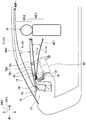
- FIG. 1 is a schematic diagram showing the arrangement of the air blowing device 10 of the present embodiment in the vehicle interior and the flow of air blown out by the air blowing device 10 into the vehicle interior.
- the air blowing device 10 is used, for example, as a part of an air outlet and a duct of an air conditioning unit 90 installed in front of a vehicle in a vehicle interior.
- the air blowing device 10 is provided on the instrument panel 70.
- the instrument panel 70 is disposed in front of the vehicle in the passenger compartment, and includes a driver seat 74 on which a driver 72 is seated and a passenger seat on which a passenger 73 (see FIG. 11) is seated. It arrange
- the driver's seat 74 is disposed on the right side toward the front of the vehicle, and the passenger seat is disposed on the left side toward the front of the vehicle (see FIG. 11).
- 1 indicates the vehicle longitudinal direction DR1
- arrow DR2 indicates the vehicle vertical direction (vehicle top-down direction) DR2, and arrow DR3 in FIG. 2 described later indicates the vehicle left-right direction DR3, that is, the vehicle width direction DR3. Yes.
- These three directions DR1, DR2, DR3 are directions orthogonal to each other.
- the instrument panel 70 has a meter panel 76 including a meter 761 such as a speedometer or a tachometer, and a meter hood 78 that covers the upper side of the meter panel 76.
- a meter 761 such as a speedometer or a tachometer
- a meter hood 78 that covers the upper side of the meter panel 76.
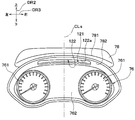
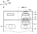
- FIG. 2 is a view of the meter panel 76 and the meter hood 78 as viewed from the driver 72 in the driving posture with the steering wheel 80 omitted.
- the meter panel 76 includes, in addition to the two meters 761, a meter peripheral portion 762 that constitutes the periphery of the meter 761.
- the meter panel 76 is arranged so that the two meters 761 and the meter peripheral portion 762 can be seen when the meter panel 76 is viewed from the driver's seat 74 side.
- the meter hood 78 is provided so as to extend in the vehicle width direction DR3 above the meter panel 76 (above the vehicle), and protrudes rearward of the meter panel 76. Since the meter hood 78 protrudes toward the rear of the vehicle, the meter hood 78 has a hood rear end 781 positioned most rearward of the meter hood 78.
- the meter hood 78 has a hood lower surface 782, and the hood lower surface 782 extends obliquely downward from the hood rear end 781 toward the front of the vehicle.
- the hood lower surface 782 may be a smooth curved surface or may have a step.
- the meter panel 76 and the meter hood 78 are disposed in the front of the driver's seat 74, in other words, in front of the vehicle with respect to the driver's seat 74 in the vehicle interior.
- a steering column 82 protrudes from the lower part of the instrument panel 70 relative to the meter panel 76 toward the driver's seat 74, and a steering wheel 80 is provided at the tip of the steering column 82.
- the steering wheel 80 is disposed between the meter panel 76 and the driver seat 74 in the vehicle longitudinal direction DR1. That is, the steering wheel 80 is disposed in front of the driver seat 74 at a position closer to the driver seat 74 than the meter panel 76 and the meter hood 78. Similar to a general vehicle steering wheel, the steering wheel 80 has a ring shape formed around the central axis of the steering column 82 that faces obliquely upward toward the rear of the vehicle. Further, the center position of the driver's seat 74, the center position of the meter panel 76, and the center position of the meter hood 78 coincide with the center position CLs (see FIG. 2) of the steering wheel 80 in the vehicle width direction DR3.
- FIG. 3 is an enlarged detail view of the air blowing device 10 and its neighboring components extracted from FIG.
- the air blowing device 10 and the steering wheel 80 in FIG. 3 are displayed in a cross section orthogonal to the vehicle width direction DR3 (see FIG. 2).
- the air blowing device 10 is a device that blows out blown air from the air conditioning unit 90.
- the air conditioning unit 90 functions as a blower that sends air to the air blowing device 10.
- the air conditioning unit 90 is a well-known device that is arranged in the instrument panel 70 (see FIG. 1) and blows out the conditioned air whose temperature is adjusted toward the passenger compartment.
- the air conditioning unit 90 is the same as the indoor air conditioning unit disclosed in Japanese Patent Application Laid-Open No. 2013-082398.
- the air blowing device 10 is configured to blow the blown air from the blowing unit 12, the first outlet door 14, the first duct unit 16, and the air conditioning unit 90 that blows the blown air from the air conditioning unit 90.
- the blowing part 12 includes a blowing part 18 that blows out in parallel, a second duct part 22, and an air volume adjusting door 24.
- the air outlet 12 is referred to as the A air outlet 12
- the air outlet 18 is referred to as the B air outlet 18
- the air volume adjusting door 24 is referred to as the A air volume adjusting door 24.
- the A outlet 12 is provided integrally with the meter hood 78, and the A outlet 12 is formed with an outlet 121 that opens to blow the air blown from the air conditioning unit 90 to the rear of the vehicle. .
- the air outlet 121 opens at the hood lower surface 782 of the meter hood 78.
- the blower outlet 121 is formed in the vehicle rear with respect to the upper end of the transparent meter window 84 arrange
- the air outlet 121 is referred to as an A air outlet 121.
- the A outlet 121 is opened so that the air blown from the air conditioning unit 90 is blown out to the rear of the vehicle through the inside of the steering wheel 80 as indicated by an arrow FL1.
- the arrow FL1 represents the main flow of the blown air blown out from the A outlet 121.
- the main flow of the blown air only needs to reach the driver through the inside of the steering wheel 80, and the entire blown air is the steering wheel. There is no need to go inside 80.
- the meter window 84 is, for example, a transparent acrylic plate, and is a so-called non-reflective plate that suppresses reflection to the driver 72 (see FIG. 1). Further, the meter window 84 is warped such that the lower end of the meter window 84 is located at the rear of the vehicle. The lowering of the meter window 84 improves the mountability of the A outlet 12.
- the A outlet 121 opens toward the rear of the vehicle at the hood lower surface 782 and is symmetrical in the vehicle width direction DR3 with respect to the center position CLs of the steering wheel 80. Is formed.
- the A outlet 121 is open so as to be thin in the vehicle vertical direction DR2 and to expand in the vehicle width direction DR3.
- the A blowing part 12 can blow toward the driver 72 a symmetric airflow in the vehicle width direction DR3 with the center position CLs of the steering wheel 80 as the center.
- a blowout air passage 123 extending from the A blower outlet 121 to the front of the vehicle is formed in the A blowout part 12.
- the blown air from the air conditioning unit 90 flows into the blown air passage 123, and the blown air passage 123 flows the blown air into the A outlet 121.
- the A outlet 12 has an outlet peripheral edge 122 that forms the periphery of the A outlet 121 and a passage inner wall surface 124 that surrounds the outlet air passage 123.
- the inner wall surface 124 of the passage extends from the outlet peripheral edge 122 to the front of the vehicle.
- the passage inner wall surface 124 is inclined so that the front side of the passage inner wall surface 124 in the vehicle longitudinal direction DR1 is lowered with respect to the rear side.
- the passage inner wall surface 124 is formed such that an upper portion 124a of the passage inner wall surface 124 extends obliquely downward from the upper portion 122a of the outlet peripheral portion 122 toward the front of the vehicle. .
- the passage inner wall surface 124 is formed so that the upper portion 124a of the passage inner wall surface 124 extends obliquely upward toward the rear of the vehicle toward the upper portion 122a of the outlet peripheral edge portion 122. Yes.
- the A outlet 12 has a plurality of thin plate-like outlet ribs 125.
- Each of the air outlet ribs 125 has an A air outlet that crosses the A air outlet 121 in the vehicle width direction DR3 with the direction perpendicular to the flow direction of air blown from the air outlet 121 (see arrow FL1) as the thickness direction. It is installed in 121.
- the blower outlet rib 125 prevents foreign matter intrusion from the A blower outlet 121 in the A blower part 12 while preventing the air flow blown out by the A blower outlet 121.
- the first air outlet door 14 is provided in the A air outlet 12 and is an air outlet direction adjusting device that adjusts the air outlet direction from the air outlet 121.
- the blowing direction of the air blowing from the A outlet 121 is, for example, the direction indicated by the arrow FL1 in FIG.
- the first air outlet door 14 has a flat air guide member 141, and the air guide member 141 is arranged so as to extend in the vehicle longitudinal direction DR1 and the vehicle width direction DR3. And the air guide member 141 has the front-end part 141a located in the vehicle forward in the air guide member 141.
- FIG. The first air outlet door 14 adjusts the blowing direction by the rotation operation of the air guide member 141, and the front end portion 141 a of the air guide member 141 is the rotation center of the air guide member 141.
- the air guide member 141 only slightly rotates with respect to the horizontal direction of the air guide member 141.
- the air guide member 141 is within the rotation range of the air guide member 141 from the upper position indicated by the solid line to the lower position indicated by the two-dot chain line in FIG. To rotate. Accordingly, the air guide member 141 rotates about the front end portion 141a, so that the rear end portion 141b opposite to the front end portion 141a in the vehicle front-rear direction DR1 moves up and down.
- the air guide member 141 is disposed on the upper side in the blown air passage 123.
- the air guide member 141 is disposed such that at least a part of the air guide member 141 is located in the upper region of the blown air passage 123.
- region of the blowing air path 123 means the area
- the air guide member 141 is in a state along the upper portion 124a of the passage inner wall surface 124 as shown in FIG. 3 at the upper position where the rear end portion 141b of the air guide member 141 is located on the uppermost side.
- the air guide member 141 is disposed so that the entire air guide member 141 is located in the upper region of the blowing air passage 123.
- the lower plane that is, the lower surface 141c of the air guide member 141 is an air guide surface 141c along which the air blown from the A outlet 121 flows. That is, the 1st blower outlet door 14 adjusts the blowing direction of the air which blows off from A blower outlet 121 by the angle change of the lower surface 141c as the air guide surface 141c. More specifically, the air guide member 141 rotates about the front end portion 141a to adjust the blowing direction of the air blown from the A outlet 121 up and down as indicated by an arrow AR1 in FIG. For example, the air from the A outlet 121 is blown into the wind direction range WD1 from the face of the driver 72 to the vicinity of the pigtail by adjusting the first outlet door 14.
- FIG. 4 is a side view similar to FIG. 1, and is a view showing a blowing range of air blown out by the air blowing device 10 into the vehicle interior.
- arrow FL1a shows the air flow which flows the uppermost side among the ventilation ranges (blowout range) of A blowing part 12
- arrow FL1b shows the air flow which flows the lowest side among the blowing ranges of A blowing part 12 ing.
- the air guide surface 141c is referred to as an A air guide surface 141c.
- the 1st blower outlet door 14 is the driver
- the A air outlet 121 and the first air outlet door 14 that rotates in the A air outlet 121 support the rear head of the driver 72 and are viewed from a headrest 741 (see FIG. 1) that constitutes the upper end portion of the driver seat 74.
- the wheel 80 and the meter hood 78 are disposed so as to be hidden.
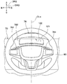
- FIG. 5 is a view of the meter panel 76, the meter hood 78, and the steering wheel 80 as viewed from the driver 72 in the driving posture.
- the B blowing unit 18 is an air blowing unit that blows air blown from the air conditioning unit 90 in parallel with the A blowing unit 12 as shown in FIG. 3.
- the B outlet 18 is provided integrally with the A outlet 12 and is disposed in front of the vehicle with respect to the A outlet 12. That is, the B outlet 18 is arranged in front of the vehicle with respect to the meter hood 78.
- the B outlet 18 is formed with an outlet 181 that blows out the air blown from the air conditioning unit 90 in parallel with the A outlet 121.
- This air outlet 181 opens upward and is disposed in front of the vehicle from the A air outlet 121.
- the air outlet 181 is formed symmetrically in the vehicle width direction DR3 with reference to the center position CLs of the steering wheel 80 (see FIG. 11).
- the B blowing part 18 can blow toward the driver 72 a symmetric airflow in the vehicle width direction DR3 with the center position CLs of the steering wheel 80 as the center.
- the air outlet 181 is referred to as a B air outlet 181.
- the B outlet 18 changes the direction of the air flow blown from the B outlet 181 on the same principle as that of the air blowing device described in Japanese Patent Application Laid-Open No. 2014-210564. That is, the B blowing unit 18 uses the Coanda effect to change the blown air flow toward the rear of the vehicle.
- the B outlet 18 has an air guide surface 182 in order to change the blown air flow toward the rear of the vehicle.
- the air guide surface 182 is an outlet rear surface that forms a portion of the B outlet 181 on the vehicle rear side.
- the air guide surface 182 is a curved surface having a convex shape in the cross-sectional shape viewed from the vehicle width direction DR3 (see FIG. 2), that is, the cross-sectional shape shown in FIG.
- the air guide surface 182 is curved so that the air flow downstream side of the air guide surface 182 warps rearward of the vehicle.
- the air guide surface 182 is smoothly connected to the upper surface 701 of the instrument panel 70 at the downstream end of the air flow of the air guide surface 182.
- the air guide surface 182 is referred to as a B air guide surface 182.
- the B outlet 18 has a second outlet door 183.
- the second air outlet door 183 is a flat door that is disposed inside the B air outlet 181 and rotates around a central axis 183a extending in the vehicle width direction DR3.
- the second outlet door 183 rotates by electrical control of the electronic control unit.
- the second air outlet door 183 has a passage cross-sectional area of the rear air passage 181 a formed between the second air outlet door 183 and the B air guide surface 182 in the B air outlet 181. Increase / decrease by rotating motion.
- the second air outlet door 183 increases the flow velocity of the air flow passing through the rear air passage 181a by restricting the rear air passage 181a in this way, and the air flow is made to the B air guide surface 182 by the Coanda effect.
- a high-speed airflow FLH1 that bends along.
- air also flows through the front air passage 181b formed in front of the vehicle from the second outlet door 183 in the B outlet 181.
- the air flow passing through the front air passage 181b becomes a low-speed air flow FLL1 that is slower than the high-speed air flow FLH1 passing through the rear-side air passage 181a, and is attracted to the high-speed air flow FLH1. Therefore, the air passing through the front air passage 181b flows to the rear of the vehicle as indicated by the arrow FL2 (see FIG. 1) together with the air passing through the rear air passage 181a.
- the B outlet 18 directs the air blown out from the B outlet 181 to the rear of the vehicle along the B air guide surface 182, and also directs the air flow toward the rear of the vehicle to the steering wheel.
- An upper side of 80 is formed as indicated by an arrow FL2.
- the blowing direction of the air blown out from the B blower outlet 181 depends on the flow rate of the air flowing into the B blower portion 18 and the rotation angle of the second blower outlet door 183 as indicated by an arrow AR2. Adjusted up and down.
- the air from the B outlet 181 is blown into the wind direction range WD2 by adding the face of the rear seat occupant to the range from the head of the driver 72 to the vicinity of the throat by adjusting the second outlet door 183. It has become so.
- FIG. 4 the blowing direction of the air blown out from the B blower outlet 181 depends on the flow rate of the air flowing into the B blower portion 18 and the rotation angle of the second blower outlet door 183 as indicated by an arrow AR2. Adjusted up and down.
- the air from the B outlet 181 is blown into the wind direction range WD2 by adding the face of the rear seat occupant to the range from the head of the driver 72 to the vicinity of the throat by adjusting the second outlet door 183. It has become so.
- an arrow FL ⁇ b> 2 a indicates an air flow that flows on the uppermost side in the blowing range of the B blowing unit 18
- an arrow FL ⁇ b> 2 b indicates an air flow that flows on the lowest side in the blowing range of the B blowing unit 18.
- the B blowing portion 18 reaches the rear seat where the air blown from the B blowing port 181 exceeds the head of the driver 72 within the blowing range of the B blowing portion 18. You can blow out air as you do.
- the B blowing unit 18 can cause the blown air to reach the rear seat by blowing air in the blowing direction indicated by the arrow FL2a.
- the first duct portion 16 is an intermediate duct portion interposed between the A blowout portion 12 and the A air volume adjusting door 24. That is, the first duct portion 16 is formed with a first duct passage 161 that is an air passage through which the air blown from the air conditioning unit 90 flows.
- the first duct passage 161 is provided on the upstream side of the air flow with respect to the blowing air passage 123 of the A blowing portion 12. As a result, the blown air from the air conditioning unit 90 flows into the first duct passage 161, and the first duct portion 16 flows the blown air that has flowed into the first duct passage 161 into the blown air passage 123.
- the second duct portion 22 is interposed between the B blowing portion 18 and the A air volume adjusting door 24.
- the second duct portion 22 is formed with a second duct passage 221 that is an air passage through which blown air from the air conditioning unit 90 flows.
- the air blown from the air conditioning unit 90 flows in as indicated by an arrow FLin, and two air flow downstream ends of the upstream duct portion 28 provided on the air flow upstream side of the A air volume adjusting door 24 are provided.
- Duct portions 16 and 22 are connected. One of the two duct portions 16 and 22 is the first duct portion 16 and the other is the second duct portion 22.
- the upstream air passage 281 formed in the upstream duct portion 28 branches into a first duct passage 161 and a second duct passage 221 at the position where the A air volume adjusting door 24 is disposed.
- first duct portion 16 and second duct portion 22 are both arranged to flow air from the bottom to the top, and are provided in front of the vehicle with respect to the meter panel 76.
- first duct portion 16 and the second duct portion 22 are provided so as to overlap the front of the vehicle with respect to the meter panel 76.
- the 1st duct part 16 and the 2nd duct part 22 will comprise one resin-made duct member, for example. .
- the second duct portion 22 is provided in front of the vehicle with respect to the first duct portion 16.
- the A air volume adjusting door 24 is an air volume adjusting device that adjusts the air volume ratio between the air volume blown from the A outlet 121 and the air volume blown from the B outlet 181. As shown in FIG. 3, the A air volume adjusting door 24 is disposed at a connection position between the upstream air passage 281, the first duct passage 161, and the second duct passage 221.
- the A air volume adjusting door 24 is a flat-plate-shaped rotating door that rotates around a central axis 24a extending in the vehicle width direction DR3.
- the A air volume adjusting door 24 is rotated by electrical control of the electronic control unit.
- the A air volume adjusting door 24 increases or decreases the opening area of the entrance of the first duct passage 161 and the opening area of the entrance of the second duct passage 221 according to the rotational position of the A air volume adjusting door 24.
- the A air volume adjusting door 24 adjusts the air volume ratio by increasing or decreasing the opening area.
- the A air volume adjustment door 24 continuously rotates within a rotation range from the first position DP1 to the second position DP2.
- the first position DP1 is a position where the inlet of the first duct passage 161 is set to the maximum opening, while the inlet of the second duct passage 221 is fully closed
- the second position DP2 is the second duct passage.
- the A air volume adjusting door 24 is positioned at an intermediate position between the first position DP ⁇ b> 1 and the second position DP ⁇ b> 2, thereby blowing out blown air from both the A blowing part 12 and the B blowing part 18.
- the A air volume adjusting door 24 calls the air flow FL1 (referred to as the first air flow FL1) blown from the A outlet 121 and the air flow FL2 (referred to as the second air flow FL2) blown from the B outlet 181. ) Can be changed.
- the A air volume adjusting door 24 is positioned at a predetermined position within the rotation range of the A air volume adjusting door 24, thereby realizing the air flows FL1 and FL2 as shown in FIG. That is, the A air volume adjustment door 24 has a difference in wind speed at which the wind speed of the second air flow FL2 is smaller than the wind speed of the first air flow FL1, and the second air flow FL2 is attracted to the first air flow FL1.
- FIG. 6 is a view showing one state of the air flow that the air blowing device 10 blows into the vehicle interior, and the second air flow FL2 from the B outlet 181 is the first air flow from the A outlet 121. It is the schematic diagram which showed a mode that it was drawn near to FL1.
- FIG. 7 is a schematic diagram schematically showing the air flow that the air blowing device 10 blows out into the vehicle compartment during cool-down
- FIG. 8 shows the air flow that the air blowing device 10 blows out into the vehicle compartment during steady operation. It is the schematic diagram shown typically.
- an A outlet 121 is formed in the A outlet 12, and the A outlet 121 passes air from the air conditioning unit 90 through the inside of the steering wheel 80 to the rear of the vehicle.
- the meter hood 78 is opened so as to blow out. Therefore, air can be blown out from the A outlet 121 which is large and opened near the driver 72 as shown in FIG. Therefore, it is possible to blow air from the front of the driver 72 to the driver 72 with a sufficient air volume.
- the 1st blower outlet door 14 adjusts the blowing direction of the air which blows off from A blower outlet 121 by the angle change of A air guide surface 141c, as shown in FIG. Therefore, it is possible to adjust the air blowing direction while ensuring a large amount of air blown from the A outlet 121.
- the air from the A outlet 121 is not blown out only to the local part in the driver 72, but the air from the A outlet 121 to the driver 72 in a wide range (for example, FIG. 4). In the wind direction range WD1).
- the air blown out from the A outlet 121 can be prevented from facing the eyes of the driver 72 by adjusting the first outlet door 14, the driver is prevented from deteriorating the comfort of the driver 72. It is possible to improve the immediate cooling of 72 face parts or head parts.
- the vehicle display device disclosed in Patent Document 1 does not have a function of adjusting the direction of the airflow blown from the inside of the meter. It is quite possible to collide with obstacles such as columns. In addition, the air current is bent due to the Coanda effect that is caused by the flow of the blown air current in the vicinity of the obstacles, and it is easily imagined that airflow control is difficult.
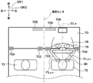
- FIG. 10 is a schematic view of the front portion of the vehicle in the passenger compartment as viewed from above the vehicle in a comparative example compared with the present embodiment.
- a defroster opening 705 and a HUD (head-up display) device 706 are provided in the instrument panel 70.
- FIG. 11 is a schematic view of the front part of the vehicle in the passenger compartment as viewed from above the vehicle in the present embodiment.
- the hood lower surface 782 of the meter hood 78 is formed below the hood rear end 781 and extends obliquely downward toward the front of the vehicle. ing.
- the A blower outlet 121 is opened in the hood lower surface 782 toward the vehicle rear. Therefore, the A outlet 121 can directly blow air toward the driver 72, and does not appear directly behind the steering wheel 80 and the meter hood 78 from the driver 72 taking the driving posture. It has become. Therefore, the air blowing device 10 of the present embodiment is superior in design as compared with the vehicle display device of Patent Document 1 in which the blowing opening is directly visible from the driver's 72 line of sight.
- FIG. 9 is a view of the meter panel 76, the meter hood 78, and the steering wheel 80 when viewed from a position below the steering wheel 80 in the driver's seat 74.
- the hood lower surface 782 in which the A outlet 121 is open is a surface extending obliquely downward toward the front of the vehicle below the hood rear end 781 as shown in FIG. Therefore, the A outlet 121 can be hidden behind the meter hood 78 from the line of sight of the driver 72 taking the driving posture, and, for example, compared to the configuration in which the A outlet 121 is open on the upward surface, There is a merit that foreign matter hardly enters the A outlet 121.
- the air guide member 141 of the first outlet door 14 is disposed closer to the upper side in the outlet air passage 123.
- the air guide member 141 is disposed such that at least a part of the air guide member 141 is located in the upper region of the blown air passage 123. Therefore, it is possible to adjust the blow-out direction of the air blown out from the A blower outlet 121 by the first blower outlet door 14 while making the first blower outlet door 14 invisible from the line of sight of the driver 72 taking the driving posture. is there.
- the air guide member 141 is disposed so that the entire air guide member 141 is located in the upper region of the blown air passage 123.
- the outlet door 14 is not particularly visible.
- the passage inner wall surface 124 of the A blowing portion 12 has the upper portion 124a of the passage inner wall surface 124 extended obliquely downward from the upper portion 122a of the outlet peripheral edge portion 122 toward the front of the vehicle. It is formed as follows. In other words, the passage inner wall surface 124 of the A blowing portion 12 has an upper portion 124 a of the passage inner wall surface 124 extending obliquely upward toward the vehicle rear toward the upper portion 122 a of the blower outlet peripheral portion 122. It is formed as follows. Accordingly, the A blowout portion 12 has an upper side in the air blowing range of the A blowout portion 12 (that is, the wind direction range WD1 in FIG. 4) as compared with a configuration in which the upper portion 124a of the passage inner wall surface 124 extends horizontally, for example. Can be raised upward. For example, in the present embodiment, the upper limit is raised to around the face of the driver 72.
- the A outlet portion 12 and the first duct portion 16 are configured integrally with the meter panel 76. Thus, it is easy to make them one unit.
- the blower outlet rib 125 is installed so as to cross the A blower outlet 121 without disturbing the air flow blown out by the A blower outlet 121. Prevent foreign material intrusion. Therefore, it is possible to prevent foreign matter from entering the inside of the air blowing device 10.
- the air outlet rib 125 is installed in the A air outlet 121, it is possible to prevent the intrusion of foreign matter so as not to affect the driver's 72 viewing the meter 761 and the like of the meter panel 76.
- the A outlet 121 and the B outlet 181 are formed symmetrically in the vehicle width direction DR3 with respect to the center position CLs of the steering wheel 80. Has been. Therefore, the left-right balance of the airflow blown from the air blowing device 10 can be kept symmetrical about the driver 72. Therefore, it is possible to blow air directly to the driver 72 while ensuring the comfort of the driver 72.
- the B outlet 18 forms an air flow toward the rear of the vehicle on the upper side of the steering wheel 80, so that the meter hood 78 is the boundary in the vehicle vertical direction DR ⁇ b> 2.
- a two-layer airflow overlapping the vehicle vertical direction DR2 is formed.
- the air from the B outlet 18 constituting the upper airflow of the two layers of airflow is mainly blown around the face of the driver 72. Further, the B outlet 18 can blow air to the rear seat beyond the head of the driver 72.
- the air from the A blowing section 12 constituting the lower airflow among the two layers of airflow can be blown to the face of the driver 72 and the entire chest, and mainly blown around the chest of the driver 72. Is done.
- the combined use of the A blowout unit 12 and the B blowout unit 18 as described above can cover the wind direction range that is necessary to blow air to the driver 72 during cooling, that is, the wind direction range from the head of the driver 72 to the pigeon tail. Is possible. In addition, it is possible to blow air to the face of the rear seat occupant. Therefore, compared with the comparative example of FIG. 10, for example, in this embodiment, the comfort in the passenger compartment can be significantly improved.
- the A air volume adjusting door 24 has an air volume ratio between the air volume blown from the A outlet 121 and the air volume blown from the B outlet 181 as shown in FIG. Adjust. Therefore, it is possible to change the wind speed of the air blown out from the A outlet 121 and the B outlet 181 by making a difference in the respective air volumes of the two-layer airflows. Thereby, it becomes easy to realize the air flow according to the preference of the driver 72.
- the A air volume adjusting door 24 is positioned at a predetermined position within the rotation range of the A air volume adjusting door 24, thereby realizing the air flows FL1 and FL2 as shown in FIG. . That is, the A air volume adjustment door 24 has a difference in wind speed at which the wind speed of the second air flow FL2 is smaller than the wind speed of the first air flow FL1, and the second air flow FL2 is attracted to the first air flow FL1.
- the air volume ratio between the air blown from the A outlet 121 and the air blown from the B outlet 181 is adjusted so as to be generated between the air flow FL1 and the second air flow FL2. Accordingly, when the upper second air flow FL2 is attracted to and merged with the lower first air flow FL1 as shown in FIG. 6, the direction of the first air flow FL1 is obliquely lower due to the influence of the second air flow FL2. Will turn to.
- the A air volume adjusting door 24 uses the second air flow FL2 to adjust the air volume ratio between the air volume from the A air outlet 121 and the air volume from the B air outlet 181, and thereby It is possible to expand the wind direction range of the air flow FL1 downward.
- the air blowing device 10 of the first embodiment is mainly configured to include a blowing unit 19. Since the rest is basically the same as that of the first embodiment, only the parts different from the first embodiment will be described. In the following, the blowing part 19 is referred to as a C blowing part 19.
- the air blowing device 10 includes a C blowing unit 19 that blows out the blown air from the air conditioning unit 90.
- the C blowout part 19 is provided integrally with the meter hood 78, and the C blowout part 19 is more than the A outlet 121 in the meter hood 78 so that the air from the air conditioning unit 90 is blown out rearward of the vehicle.
- An air outlet 191 that opens on the upper side is formed. Specifically, the air outlet 191 opens at a hood upper surface 783 located on the opposite side of the hood lower surface 782 across the hood rear end 781 of the meter hood 78.
- the air outlet 191 is open upward.
- the air outlet 191 is provided with a branch passage 192 formed so that the air from the air conditioning unit 90 is branched from the air outlet passage 123 and flows to the air outlet 191.
- the air outlet 191 is referred to as a C air outlet 191.
- the C outlet 19 is formed symmetrically in the vehicle width direction DR3 with respect to the center position CLs of the steering wheel 80.
- the B blowing part 18 can blow toward the driver 72 a symmetric airflow in the vehicle width direction DR3 with the center position CLs of the steering wheel 80 as the center.
- the C outlet 19 changes the direction of the air flow blown from the C outlet 191 on the same principle as that of the air blowing device described in JP-A-2014-210564. That is, the C blowing unit 19 uses the Coanda effect to change the blown air flow toward the rear of the vehicle.
- the C blowing unit 19 has an air guide surface 193 in order to change the blown air flow toward the rear of the vehicle.
- the air guide surface 193 is an outlet rear surface that forms a portion of the C outlet 19 on the vehicle rear side.
- the air guide surface 193 is a curved surface having a convex shape in the cross-sectional shape seen from the vehicle width direction DR3 shown in FIG. 2, that is, the cross-sectional shape shown in FIG.
- the cross-sectional shape seen from the vehicle width direction DR3 means the shape of a cross section orthogonal to the vehicle width direction DR3.
- the air guide surface 193 is referred to as a C air guide surface 193.
- the air guide surface 193 is curved so that the air flow downstream side of the air guide surface 193 warps rearward of the vehicle.
- the air guide surface 193 is smoothly connected to the hood upper surface 783 at the air flow downstream end of the air guide surface 193.
- the C outlet 19 has an outlet door 194.
- the outlet door 194 is a flat pivot door that is disposed inside the C outlet 19 and pivots about a central axis 194a extending in the vehicle width direction DR3.
- the air outlet door 194 rotates by electrical control of the electronic control unit.
- the air outlet door 194 is referred to as a third air outlet door 194.
- the third air outlet door 194 has a cross-sectional area of the rear air passage 191 a formed between the third air outlet door 194 and the C air guide surface 193 in the C air outlet 191. Increase / decrease by rotating motion.
- the third outlet door 194 increases the flow velocity of the air flow passing through the rear air passage 191a by restricting the rear air passage 191a in this way, and the air flow is transferred to the C air guide surface 193 by the Coanda effect.
- a high-speed airflow FLH2 that bends along.
- the air flow passing through the front air passage 191b becomes a low-speed air flow FLL2 that is slower than the high-speed air flow FLH2 passing through the rear-side air passage 191a, and is attracted to the high-speed air flow FLH2. Accordingly, as shown in FIG. 13, the air passing through the front air passage 191b flows to the rear of the vehicle as indicated by the arrow FL3 together with the air passing through the rear air passage 191a.
- the C outlet 19 directs the air blown from the C outlet 191 along the C air guide surface 193 to the rear of the vehicle, and the air flow toward the rear of the vehicle is directed to the steering wheel.
- An upper side of 80 is formed as indicated by an arrow FL3.
- the blowing direction of the air which blows off from C blower outlet 191 is as shown by arrow AR3 according to the flow rate of the air which flows into C blower part 19, and the rotation angle of the 3rd blower outlet door 194. Adjusted up and down.
- air from the C outlet 191 is blown into the wind direction range WD3 by adding the face of the rear seat occupant to the range from the head of the driver 72 to the vicinity of the throat by adjusting the third outlet door 194. It has become so.
- FIG. 14 the blowing direction of the air which blows off from C blower outlet 191 is as shown by arrow AR3 according to the flow rate of the air which flows into C blower part 19, and the rotation angle of the 3rd blower outlet door 194. Adjusted up and down.
- air from the C outlet 191 is blown into the wind direction range WD3 by adding the face of the rear seat occupant to the range from the head of the driver 72 to the vicinity of the throat by adjusting the third outlet door 194. It has become so.
- an arrow FL ⁇ b> 3 a indicates an air flow that flows on the uppermost side in the blowing range of the C blowing unit 19
- an arrow FL ⁇ b> 3 b indicates an air flow that flows on the lowest side in the blowing range of the C blowing unit 19.
- the air blown out from the C outlet 191 is increased as the flow sectional area of the rear air passage 191a is reduced by the third outlet door 194 and the flow velocity of the high-speed airflow FLH2 passing through the rear air passage 191a is increased.
- the blowing direction changes from the direction of the arrow FL3a to the direction of the arrow FL3b.
- the first duct portion 16 is configured to have a branch passage 192 that branches from the blowing air passage 123. That is, the first duct passage 161 is provided on the upstream side of the air flow with respect to the branch passage 192. Therefore, in the air blowing device 10 according to the present embodiment, the blown air from the air conditioning unit 90 flows into the first duct passage 161, and the first duct unit 16 uses the blown air that has flowed into the first duct passage 161 to the branch passage. Flow to 192.
- an air volume adjusting door 30 is arranged in the first duct portion 16 on the upstream side of the blown air passage 123. That is, the air passage in the first duct portion 16 is branched into the blowing air passage 123 and the branch passage 192 by the arrangement of the air volume adjusting door 30.
- the air volume adjusting door 30 is referred to as a B air volume adjusting door 30.
- the B air volume adjusting door 30 is an air volume adjusting device that adjusts the air volume ratio between the air volume blown from the A outlet 121 and the air volume blown from the C outlet 191.
- the B air volume adjustment door 30 is a flat-plate-like pivoting door that pivots about a central axis 30a extending in the vehicle width direction DR3.
- the B air volume adjusting door 30 is rotated by electrical control of the electronic control unit.
- a so-called cantilever door is adopted as the B air volume adjusting door 30, but the B air volume adjusting door 30 is not limited to this configuration, but a butterfly door or a sliding door is adopted. Also good.
- the B air volume adjusting door 30 increases or decreases the opening area of the inlet of the blowing air passage 123 and the opening area of the inlet of the branch passage 192 according to the rotation position of the B air volume adjusting door 30.
- the B air volume adjusting door 30 adjusts the air volume ratio by increasing or decreasing the opening area.
- the B air volume adjusting door 30 has a maximum opening degree at the inlet of the branch passage 192 from the first position DP3 where the inlet of the outlet passage 123 is fully closed while the inlet of the branch path 192 is fully closed. It rotates continuously within the rotation range up to the second position DP4 where the inlet of the blown air passage 123 is fully closed.
- the B air volume adjusting door 30 is positioned at an intermediate position between the first position DP3 and the second position DP4, and blows air from both the A blowing part 12 and the C blowing part 19.
- the B air volume adjusting door 30 changes the difference in wind speed generated between the first air flow FL1 blown from the A outlet 121 and the air flow FL3 blown from the B outlet 181 (referred to as the third air flow FL3). Can be made.
- the air flow FL3 is referred to as a third air flow FL3.
- FIG. 12 is a view showing one state of the air flow that the air blowing device 10 blows into the vehicle interior, and the third air flow FL3 from the C blower outlet 191 is the first air flow from the A blower outlet 121. It is the schematic diagram which showed typically a mode that it flowed without being attracted to FL1.
- the A outlet 121 is opened at the hood lower surface 782 of the meter hood 78, but the opening location is not limited thereto. It may be open at the meter peripheral portion 762 of the meter panel 76 instead of 782. In short, the A outlet 121 only needs to be open somewhere in the meter peripheral region including the meter peripheral portion 762 and the meter hood 78 which are portions of the meter panel 76 excluding the meter 761.
- the hood lower surface 782 of the meter hood 78 in which the A outlet 121 is open is configured with a smooth curved surface, but the hood lower surface 782 does not have to be smooth.
- a step may be provided on the hood lower surface 782.
- a plurality of outlet ribs 125 are provided in the A outlet 121, but the outlet ribs 125 may be omitted.
- a plurality of similar outlet ribs 125 may be provided in the C outlet 191. That is, each of the air outlet ribs 125 is formed in the C air outlet 191 so as to cross the C air outlet 191 in the vehicle width direction DR3 with the direction orthogonal to the flow direction FL3 of the air blown out from the C air outlet 191 as the thickness direction. It may be installed. Thereby, the foreign matter intrusion from the C outlet 191 can be prevented in the C outlet 19 while preventing the air flow blown out from the C outlet 191.
- the C outlet 191 is opened at the hood upper surface 783 of the meter hood 78.
- the opening location need not be limited thereto, and for example, the C outlet 191 may be opened at the hood lower surface 782 of the meter panel 76 instead of the hood upper surface 783.
- the C outlet 191 only needs to be opened somewhere in the meter peripheral region formed by the meter peripheral portion 762 and the meter hood 78 which are portions of the meter panel 76 excluding the meter 761.
- the B outlet 18 may be omitted.
- the air is blown out from the C outlet 191 due to the provision of the C outlet 19, the air is blown above the air blown out from the A outlet 121 without the B outlet 18.
- another part such as a head-up display can be provided at a position where the B outlet 18 is provided, that is, in front of the A outlet 121 and the C outlet 191.
- the B air outlet 181 is reflected on the windshield of the vehicle due to light reflection, which may cause trouble for the driver 72.
- the blow-out portion 18 is omitted, it is difficult to cause such trouble.
- the first air outlet door 14 is provided as an air outlet direction adjusting device that adjusts the air blowing direction from the air outlet 121 up and down.
- the A outlet 12 further includes air direction adjustment louvers 40 and 50 that adjust the blowing direction of the air blowing from the A outlet 121 in the vehicle width direction. Also good.
- the A wind direction adjusting louver 40 that adjusts the blowing direction of the air blown from the A blower outlet 121 provided in the A blower part 12, and the blowing direction of the air blown from the C blower outlet 191 provided in the C blower part 19. It is set as the structure which provided the B wind direction adjustment louver 50 to adjust.
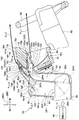
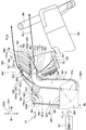
- the wind direction adjusting louvers 40 and 50 for example, a configuration that is driven by electrical control of an electronic control device and swings in the vehicle width direction to adjust the air blowing direction in the vehicle width direction can be adopted. More specifically, for example, as shown in FIG. 17, a configuration in which the wind direction adjusting louver 40 swings according to the rotation of the rotating shaft 40 a that is fixed to the A outlet 12 and rotates can be employed. Moreover, the structure which the wind direction adjustment louver 50 swings according to rotation of the rotating shaft 50a fixed to the C blowing part 19 and rotating can be employ
- a ventilation register 401 that adjusts the blowing direction of the air blown from the A outlet 121 up and down may be provided, and the ventilation register 401 that adjusts the blowing direction of the air blown from the C outlet 191 up and down.
- 501 may be provided in the C outlet 19.
- the ventilation registers 401 and 501 here mean ventilation holes whose flow rate can be adjusted.
- the present disclosure is not limited to the above-described embodiment, and can be changed as appropriate. Further, in the above-described embodiment, it is needless to say that elements constituting the embodiment are not necessarily indispensable except for the case where it is clearly indicated that the element is essential and the case where the element is clearly considered to be essential in principle. . Further, in the above embodiment, when numerical values such as the number, numerical value, quantity, range, etc. of the constituent elements of the embodiment are mentioned, it is particularly limited to a specific number when clearly indicated as essential and in principle. The number is not limited to a specific number except for cases. Further, in the above embodiment, when referring to the material, shape, positional relationship, etc. of the component, etc., unless otherwise specified and in principle limited to a specific material, shape, positional relationship, etc. The material, shape, positional relationship and the like are not limited.
Landscapes
- Engineering & Computer Science (AREA)
- Mechanical Engineering (AREA)
- Chemical & Material Sciences (AREA)
- Combustion & Propulsion (AREA)
- Transportation (AREA)
- Physics & Mathematics (AREA)
- Thermal Sciences (AREA)
- Air-Conditioning For Vehicles (AREA)
Abstract
Description
そのA吹出部に設けられ、A吹出口から吹き出る空気が沿って流れるA空気案内面を有し、A吹出口から吹き出る空気の吹出方向をA空気案内面の角度変化によって調節する吹出方向調節装置とを備えている。
図1は、本実施形態の空気吹出装置10の車室内における配置と空気吹出装置10が車室内へ吹き出す空気の流れを示した模式図である。空気吹出装置10は、例えば車室内のうちの車両前方に設置される空調ユニット90の吹出口およびダクトの一部として用いられるものである。
第2実施形態について図12~15を参照して説明する。本実施形態は、第1実施形態の空気吹出装置10に対して、主には吹出部19を備える構成としたものである。その他については基本的には第1実施形態と同様であるため、第1実施形態と異なる部分のみについて説明する。なお、以下において、吹出部19をC吹出部19と称する。
(1)上述の実施形態において、メータフード78に形成されたA吹出口121は1つであるが、複数のA吹出口121が形成されていても差し支えない。その場合には、その複数のA吹出口121の全体がステアリングホイール80の中心位置CLsを基準にして車両幅方向DR3に対称的に形成されていることが望ましい。
Claims (17)
- 車室内で運転席(74)の車両前方に配置されたメータパネル(76)のうちメータ(761)を除いた部分(762)と前記メータパネルの上側にて車両幅方向(DR3)へ拡がるように設けられ該メータパネルよりも車両後方へ突き出たメータフード(78)とから成るメータ周辺領域において、車両前後方向(DR1)で前記メータパネルと前記運転席との間に配置されたステアリングホイール(80)の内側を通して送風装置(90)からの空気を前記車両後方へ吹き出すように開口するA吹出口(121)が形成されたA吹出部(12)と、
該A吹出部に設けられ、前記A吹出口から吹き出る空気が沿って流れるA空気案内面(141c)を有し、前記A吹出口から吹き出る空気の吹出方向を前記A空気案内面の角度変化によって調節する吹出方向調節装置(14)とを備えている空気吹出装置。 - 前記メータフードは、該メータフードの中で最も前記車両後方に位置するフード後方端(781)と、該フード後方端よりも下側に形成され前記車両前方へ向かって斜め下向きに延設されたフード下面(782)とを有し、
前記A吹出口は、前記メータ周辺領域のうちの前記フード下面にて前記車両後方を向いて開口する請求項1に記載の空気吹出装置。 - 前記A吹出部には、前記A吹出口から前記車両前方へ延設され前記送風装置からの空気を前記A吹出口へ流す吹出空気通路(123)が形成され、
前記吹出方向調節装置は、前記A空気案内面が形成された板状の空気案内部材(141)を有し、
該空気案内部材は、前記吹出空気通路の中で上側寄りに配置される請求項1または2に記載の空気吹出装置。 - 前記A吹出部には、前記A吹出口から前記車両前方へ延設され前記送風装置からの空気を前記A吹出口へ流す吹出空気通路(123)が形成され、
前記吹出方向調節装置は、前記A空気案内面が形成された板状の空気案内部材(141)を有し、
前記吹出空気通路のうち前記吹出空気通路の上下方向幅の中心よりも上側の領域を前記吹出空気通路の上側領域としたとき、
前記空気案内部材は、前記空気案内部材の少なくとも一部が前記吹出空気通路の上側領域に位置するように配置される請求項1または2に記載の空気吹出装置。 - 前記A吹出部には、前記A吹出口から前記車両前方へ延設され前記送風装置からの空気を前記A吹出口へ流す吹出空気通路(123)が形成され、
前記吹出方向調節装置は、前記A空気案内面が形成された板状の空気案内部材(141)を有し、
前記吹出空気通路のうち前記吹出空気通路の上下方向幅の中心よりも上側の領域を前記吹出空気通路の上側領域としたとき、
前記空気案内部材は、前記空気案内部材の全体が前記吹出空気通路の上側領域に位置するように配置される請求項1または2に記載の空気吹出装置。 - 前記空気案内部材は、該空気案内部材の中で前記車両前方に位置する前端部(141a)を有し、該前端部を中心として回動することで、前記A吹出口から吹き出る空気の吹出方向を上下に調節する請求項3ないし5のいずれか1つに記載の空気吹出装置。
- 前記A吹出部は、前記A吹出口の周縁を形成する吹出口周縁部(122)と、前記吹出空気通路を囲んで形成する通路内壁面(124)とを有し、
該通路内壁面は、該通路内壁面のうちの上側部分(124a)が前記吹出口周縁部のうちの上側部分(122a)から前記車両前方へ斜め下向きに延設されるように形成されている請求項3ないし6のいずれか1つに記載の空気吹出装置。 - 前記A吹出部は、前記A吹出口の周縁を形成する吹出口周縁部(122)と、前記吹出空気通路を囲んで形成する通路内壁面(124)とを有し、
該通路内壁面は、該通路内壁面のうちの上側部分(124a)が、前記吹出口周縁部のうちの上側部分(122a)に向かって前記車両後方へ斜め上向きに延設されるように形成されている請求項3ないし6のいずれか1つに記載の空気吹出装置。 - 前記吹出空気通路よりも空気流れ上流側に設けられ前記送風装置からの空気を流す空気通路(161)が形成された中間ダクト部(16)を備え、
該中間ダクト部は前記メータパネルの車両前方に設けられる請求項3ないし8のいずれか1つに記載の空気吹出装置。 - 前記A吹出部は、前記A吹出口を横切るように設置され該A吹出口からの異物侵入を防止する吹出口リブ(125)を有している請求項1ないし9のいずれか1つに記載の空気吹出装置。
- 前記送風装置からの空気を前記第1吹出口と並列に吹き出すB吹出口(181)が形成されたB吹出部(18)を備え、
前記B吹出口は、上側を向いて開口し且つ前記A吹出口よりも前記車両前方に配置され、
前記B吹出部は、前記B吹出口のうち前記車両後方側の部位を形成する吹出口後方面(182)を有し、
該吹出口後方面は、該吹出口後方面の空気流れ上流側に対して空気流れ下流側が前記車両後方へ反るように湾曲し、
前記B吹出部は、前記第2吹出口から吹き出る空気を前記吹出口後方面に沿わせることで前記車両後方へ向けると共に、該車両後方へ向かう空気流れを前記ステアリングホイールの上側に形成する請求項1ないし10のいずれか1つに記載の空気吹出装置。 - 前記A吹出口から吹き出される空気の風量と前記B吹出口から吹き出される空気の風量との風量割合を調節するA風量調節装置(24)を備えている請求項11に記載の空気吹出装置。
- 前記A風量調節装置は、前記B吹出口から吹き出される空気流れの風速が前記A吹出口から吹き出される空気流れの風速に対して小さくなり、且つ、前記B吹出口からの空気流れが前記A吹出口からの空気流れに引き寄せられる風速差が前記A吹出口からの空気流れと前記B吹出口からの空気流れとの間に生じるように、前記風量割合を調節する請求項12に記載の空気吹出装置。
- 前記送風装置からの空気を前記車両後方へ吹き出すように前記メータフードのうち前記A吹出口よりも上側にて開口するC吹出口(191)が形成されたC吹出部(19)を備え、
前記A吹出部には、前記A吹出口から前記車両前方へ延設され前記送風装置からの空気を前記A吹出口へ流す吹出空気通路(123)が形成され、
前記C吹出部には、前記吹出空気通路から分岐して前記送風装置からの空気を前記C吹出口へ流すように形成された分岐通路(192)が形成されている請求項1、2、6ないし13のいずれか1つに記載の空気吹出装置。 - 前記分岐通路は、前記吹出空気通路のうち前記A空気案内面よりも空気流れ上流側から分岐している請求項14に記載の空気吹出装置。
- 前記A吹出口から吹き出される空気の風量と前記C吹出口から吹き出される空気の風量との風量割合を調節するB風量調節装置(30)を備えている請求項14または15に記載の空気吹出装置。
- 前記C吹出部には、前記C吹出口から吹き出される空気を壁面に沿わせて曲げるC空気案内面(193)が形成されている請求項14ないし16のいずれか1つに記載の空気吹出装置。
Priority Applications (3)
| Application Number | Priority Date | Filing Date | Title |
|---|---|---|---|
| DE112016001119.9T DE112016001119T5 (de) | 2015-03-11 | 2016-02-12 | Luftgebläsevorrichtung |
| JP2017504934A JP6365759B2 (ja) | 2015-03-11 | 2016-02-12 | 空気吹出装置 |
| US15/550,970 US10675947B2 (en) | 2015-03-11 | 2016-02-12 | Air blower device |
Applications Claiming Priority (2)
| Application Number | Priority Date | Filing Date | Title |
|---|---|---|---|
| JP2015048709 | 2015-03-11 | ||
| JP2015-048709 | 2015-03-11 |
Publications (1)
| Publication Number | Publication Date |
|---|---|
| WO2016143455A1 true WO2016143455A1 (ja) | 2016-09-15 |
Family
ID=56879545
Family Applications (1)
| Application Number | Title | Priority Date | Filing Date |
|---|---|---|---|
| PCT/JP2016/054109 Ceased WO2016143455A1 (ja) | 2015-03-11 | 2016-02-12 | 空気吹出装置 |
Country Status (4)
| Country | Link |
|---|---|
| US (1) | US10675947B2 (ja) |
| JP (1) | JP6365759B2 (ja) |
| DE (1) | DE112016001119T5 (ja) |
| WO (1) | WO2016143455A1 (ja) |
Cited By (3)
| Publication number | Priority date | Publication date | Assignee | Title |
|---|---|---|---|---|
| WO2019096572A1 (de) * | 2017-11-14 | 2019-05-23 | Bayerische Motoren Werke Aktiengesellschaft | Einstellbare lenkradbelüftung |
| US10538147B2 (en) | 2015-04-02 | 2020-01-21 | Denso Corporation | Vehicle air condition display device |
| US20220194166A1 (en) * | 2019-04-05 | 2022-06-23 | Dyson Technology Limited | Vehicle vent assembly |
Families Citing this family (12)
| Publication number | Priority date | Publication date | Assignee | Title |
|---|---|---|---|---|
| US10752082B1 (en) * | 2016-05-26 | 2020-08-25 | Apple Inc. | Climate control system with slit-vent fluid delivery |
| DE102018005436B4 (de) * | 2018-07-10 | 2023-01-05 | Psa Automobiles Sa | Armaturenbrett für ein Fahrzeug mit konkaver Schutzscheibe und integriertem Belüftungskanal |
| DE102019203680A1 (de) * | 2019-03-19 | 2020-09-24 | Audi Ag | Belüftungsanordnung für einen Fahrzeuginnenraum |
| WO2020189646A1 (ja) * | 2019-03-19 | 2020-09-24 | 株式会社小糸製作所 | 車両用ヘッドアップディスプレイおよび車両用ヘッドアップディスプレイシステム |
| GB2582818B (en) | 2019-04-05 | 2022-02-16 | Dyson Technology Ltd | Vehicle vent assembly |
| GB2582819B (en) | 2019-04-05 | 2024-01-03 | Dyson Technology Ltd | Vehicle vent assembly |
| DE102019110211A1 (de) * | 2019-04-17 | 2020-10-22 | Bayerische Motoren Werke Aktiengesellschaft | Frontscheibenentfroster für Fahrzeug |
| US11175054B2 (en) * | 2019-06-12 | 2021-11-16 | Haier Us Appliance Solutions, Inc. | Make-up air flow restrictor for a packaged terminal air conditioner unit |
| FR3105102B1 (fr) * | 2019-12-23 | 2022-04-08 | Faurecia Interieur Ind | Elément de garnissage de véhicule comprenant un élément fonctionnel et un aérateur |
| DE102021002173B4 (de) | 2021-04-26 | 2023-03-23 | Truma Gerätetechnik GmbH & Co. KG | Klimagerät |
| FR3130696B1 (fr) * | 2021-12-21 | 2025-01-17 | Renault Sas | Agencement d’une planche de bord équipée d’un écran d’affichage |
| DE102022003985A1 (de) | 2022-10-25 | 2024-04-25 | Mercedes-Benz Group AG | Luftdüseneinrichtung für einen Innenraum eines Kraftwagens |
Citations (6)
| Publication number | Priority date | Publication date | Assignee | Title |
|---|---|---|---|---|
| JPS56174310U (ja) * | 1980-05-28 | 1981-12-23 | ||
| JPS61105212A (ja) * | 1984-10-29 | 1986-05-23 | Mazda Motor Corp | 自動車の空調装置 |
| JPS61189820U (ja) * | 1985-05-17 | 1986-11-26 | ||
| JP2004148965A (ja) * | 2002-10-30 | 2004-05-27 | Denso Corp | 車両用空調装置 |
| JP2006206008A (ja) * | 2005-01-31 | 2006-08-10 | Nippon Plast Co Ltd | 吹出口装置 |
| JP2014210564A (ja) * | 2013-04-05 | 2014-11-13 | 株式会社デンソー | 空気吹出装置 |
Family Cites Families (15)
| Publication number | Priority date | Publication date | Assignee | Title |
|---|---|---|---|---|
| JPS61189820A (ja) * | 1985-02-15 | 1986-08-23 | Sumitomo Metal Ind Ltd | 管の矯正機 |
| DE3818666A1 (de) * | 1987-06-10 | 1988-12-29 | Volkswagen Ag | Luftkanal fuer ein kraftfahrzeug |
| JPH032801A (ja) | 1989-05-31 | 1991-01-09 | Fukui Pref Gov | 反射防止機能付与法 |
| US6019677A (en) * | 1997-08-22 | 2000-02-01 | York International Corporation | Modular integrated terminals and associated systems for heating and cooling |
| DE19852592C2 (de) * | 1998-11-14 | 2000-08-24 | Daimler Chrysler Ag | Belüftungsvorrichtung |
| FR2824297B1 (fr) * | 2001-05-04 | 2003-12-12 | Valeo Climatisation | Dispositif de diffusion d'air a l'avant d'un habitacle d'un vehicule |
| JP2005081966A (ja) | 2003-09-08 | 2005-03-31 | Calsonic Kansei Corp | 車両用表示装置 |
| JP2005207757A (ja) | 2004-01-20 | 2005-08-04 | Calsonic Kansei Corp | 車両用計器表示装置 |
| JP2005096639A (ja) | 2003-09-25 | 2005-04-14 | Calsonic Kansei Corp | 車両用物入装置 |
| JP2005096536A (ja) | 2003-09-24 | 2005-04-14 | Calsonic Kansei Corp | 車両用インストルメントパネル構造 |
| US7097316B2 (en) | 2003-08-29 | 2006-08-29 | Calsonic Kansei Corporation | Display unit for vehicle |
| JP2005207756A (ja) | 2004-01-20 | 2005-08-04 | Calsonic Kansei Corp | 光指針発生装置 |
| JP2005077204A (ja) | 2003-08-29 | 2005-03-24 | Calsonic Kansei Corp | 車両用表示装置 |
| ATE481256T1 (de) * | 2008-07-31 | 2010-10-15 | Fiat Ricerche | Motorfahrzeug-armaturenbrett mit hauptzentrale und ausgabeöffnungen für die belüftungsluft |
| JP2015020566A (ja) | 2013-07-18 | 2015-02-02 | トヨタ自動車株式会社 | 車両用空調装置の吹出口構造 |
-
2016
- 2016-02-12 DE DE112016001119.9T patent/DE112016001119T5/de not_active Ceased
- 2016-02-12 US US15/550,970 patent/US10675947B2/en not_active Expired - Fee Related
- 2016-02-12 JP JP2017504934A patent/JP6365759B2/ja not_active Expired - Fee Related
- 2016-02-12 WO PCT/JP2016/054109 patent/WO2016143455A1/ja not_active Ceased
Patent Citations (6)
| Publication number | Priority date | Publication date | Assignee | Title |
|---|---|---|---|---|
| JPS56174310U (ja) * | 1980-05-28 | 1981-12-23 | ||
| JPS61105212A (ja) * | 1984-10-29 | 1986-05-23 | Mazda Motor Corp | 自動車の空調装置 |
| JPS61189820U (ja) * | 1985-05-17 | 1986-11-26 | ||
| JP2004148965A (ja) * | 2002-10-30 | 2004-05-27 | Denso Corp | 車両用空調装置 |
| JP2006206008A (ja) * | 2005-01-31 | 2006-08-10 | Nippon Plast Co Ltd | 吹出口装置 |
| JP2014210564A (ja) * | 2013-04-05 | 2014-11-13 | 株式会社デンソー | 空気吹出装置 |
Cited By (6)
| Publication number | Priority date | Publication date | Assignee | Title |
|---|---|---|---|---|
| US10538147B2 (en) | 2015-04-02 | 2020-01-21 | Denso Corporation | Vehicle air condition display device |
| WO2019096572A1 (de) * | 2017-11-14 | 2019-05-23 | Bayerische Motoren Werke Aktiengesellschaft | Einstellbare lenkradbelüftung |
| CN111263704A (zh) * | 2017-11-14 | 2020-06-09 | 宝马股份公司 | 可调节的方向盘通风设备 |
| US12115834B2 (en) | 2017-11-14 | 2024-10-15 | Bayerische Motoren Werke Aktiengesellschaft | Adjustable steering-wheel ventilation |
| US20220194166A1 (en) * | 2019-04-05 | 2022-06-23 | Dyson Technology Limited | Vehicle vent assembly |
| US12263715B2 (en) * | 2019-04-05 | 2025-04-01 | Dyson Technology Limited | Vehicle vent assembly |
Also Published As
| Publication number | Publication date |
|---|---|
| JPWO2016143455A1 (ja) | 2017-07-20 |
| JP6365759B2 (ja) | 2018-08-01 |
| US20180043752A1 (en) | 2018-02-15 |
| US10675947B2 (en) | 2020-06-09 |
| DE112016001119T5 (de) | 2017-11-16 |
Similar Documents
| Publication | Publication Date | Title |
|---|---|---|
| JP6365759B2 (ja) | 空気吹出装置 | |
| JP6593061B2 (ja) | 空気吹出装置 | |
| JP6610784B2 (ja) | 空気吹出装置 | |
| JP6361221B2 (ja) | 空気吹出装置 | |
| JP5597423B2 (ja) | 空調用レジスタ | |
| CN105564193B (zh) | 车辆的除霜构造 | |
| JP2015016843A (ja) | 車両用空調装置 | |
| JP6318931B2 (ja) | 空気吹出装置 | |
| JP5827099B2 (ja) | レジスタ | |
| US20190168566A1 (en) | Air blowout apparatus | |
| US20200247217A1 (en) | Vehicle instrument panel structure | |
| JP6265302B2 (ja) | 空気吹出装置 | |
| JP6512302B2 (ja) | 空気吹出装置 | |
| JP2016088260A (ja) | 車室前部構造 | |
| WO2017221570A1 (ja) | 空気吹出装置 | |
| CN115362074B (zh) | 出风装置 | |
| WO2016103638A1 (ja) | 空気吹出装置 | |
| JP6394796B2 (ja) | 空気吹出装置 | |
| JP2023146679A (ja) | 風向調整装置 |
Legal Events
| Date | Code | Title | Description |
|---|---|---|---|
| 121 | Ep: the epo has been informed by wipo that ep was designated in this application |
Ref document number: 16761427 Country of ref document: EP Kind code of ref document: A1 |
|
| ENP | Entry into the national phase |
Ref document number: 2017504934 Country of ref document: JP Kind code of ref document: A |
|
| WWE | Wipo information: entry into national phase |
Ref document number: 15550970 Country of ref document: US |
|
| WWE | Wipo information: entry into national phase |
Ref document number: 112016001119 Country of ref document: DE |
|
| 122 | Ep: pct application non-entry in european phase |
Ref document number: 16761427 Country of ref document: EP Kind code of ref document: A1 |