WO2016143159A1 - 貯蔵容器の搬送台車及び搬入方法並びに放射性廃棄物の貯蔵容器 - Google Patents
貯蔵容器の搬送台車及び搬入方法並びに放射性廃棄物の貯蔵容器 Download PDFInfo
- Publication number
- WO2016143159A1 WO2016143159A1 PCT/JP2015/072293 JP2015072293W WO2016143159A1 WO 2016143159 A1 WO2016143159 A1 WO 2016143159A1 JP 2015072293 W JP2015072293 W JP 2015072293W WO 2016143159 A1 WO2016143159 A1 WO 2016143159A1
- Authority
- WO
- WIPO (PCT)
- Prior art keywords
- container
- storage container
- tank
- carrying
- area
- Prior art date
- Legal status (The legal status is an assumption and is not a legal conclusion. Google has not performed a legal analysis and makes no representation as to the accuracy of the status listed.)
- Ceased
Links
Images









Classifications
-
- B—PERFORMING OPERATIONS; TRANSPORTING
- B61—RAILWAYS
- B61B—RAILWAY SYSTEMS; EQUIPMENT THEREFOR NOT OTHERWISE PROVIDED FOR
- B61B13/00—Other railway systems
-
- B—PERFORMING OPERATIONS; TRANSPORTING
- B65—CONVEYING; PACKING; STORING; HANDLING THIN OR FILAMENTARY MATERIAL
- B65D—CONTAINERS FOR STORAGE OR TRANSPORT OF ARTICLES OR MATERIALS, e.g. BAGS, BARRELS, BOTTLES, BOXES, CANS, CARTONS, CRATES, DRUMS, JARS, TANKS, HOPPERS, FORWARDING CONTAINERS; ACCESSORIES, CLOSURES, OR FITTINGS THEREFOR; PACKAGING ELEMENTS; PACKAGES
- B65D90/00—Component parts, details or accessories for large containers
- B65D90/12—Supports
-
- B—PERFORMING OPERATIONS; TRANSPORTING
- B65—CONVEYING; PACKING; STORING; HANDLING THIN OR FILAMENTARY MATERIAL
- B65G—TRANSPORT OR STORAGE DEVICES, e.g. CONVEYORS FOR LOADING OR TIPPING, SHOP CONVEYOR SYSTEMS OR PNEUMATIC TUBE CONVEYORS
- B65G1/00—Storing articles, individually or in orderly arrangement, in warehouses or magazines
-
- B—PERFORMING OPERATIONS; TRANSPORTING
- B65—CONVEYING; PACKING; STORING; HANDLING THIN OR FILAMENTARY MATERIAL
- B65G—TRANSPORT OR STORAGE DEVICES, e.g. CONVEYORS FOR LOADING OR TIPPING, SHOP CONVEYOR SYSTEMS OR PNEUMATIC TUBE CONVEYORS
- B65G57/00—Stacking of articles
- B65G57/30—Stacking of articles by adding to the bottom of the stack
-
- G—PHYSICS
- G21—NUCLEAR PHYSICS; NUCLEAR ENGINEERING
- G21F—PROTECTION AGAINST X-RADIATION, GAMMA RADIATION, CORPUSCULAR RADIATION OR PARTICLE BOMBARDMENT; TREATING RADIOACTIVELY CONTAMINATED MATERIAL; DECONTAMINATION ARRANGEMENTS THEREFOR
- G21F9/00—Treating radioactively contaminated material; Decontamination arrangements therefor
- G21F9/28—Treating solids
- G21F9/34—Disposal of solid waste
- G21F9/36—Disposal of solid waste by packaging; by baling
Definitions
- the present invention relates to a transport cart for a storage container for carrying a radioactive waste storage container to a predetermined place in various plants, a method for transporting the storage container, and a storage container for radioactive waste.
- a radioactive waste storage facility is a storage facility for storing radioactive waste such as radioactive filter sludge and radioactive waste ion exchange resin in a water-containing state for a long period of time, and is stored in a tank for a certain period of time.
- the purpose is to remove the radioactive waste safely and easily.
- the storage facility has a tank installed in a space surrounded by radiation shielding walls.
- the tank is provided with a guide rail located on the vertical line.
- the upper radiation shielding wall in the space is provided with an upper end opening, and the opening is closed by a plug-like lid made of a radiation shielding material.
- the radioactive waste storage and transfer device described in Patent Document 1 has an open air container for storing radioactive waste, an agitation transfer pump placed in the shielded water of the container, and a transfer pipe connected to the pump. The radioactive waste and the shielding water are stirred and mixed and then discharged from the transfer pipe.
- the radioactive waste storage container described in Patent Document 2 is configured by joining a cylindrical upper container and a lower container by welding.
- Patent Document 2 as a method for carrying in a storage container, a storage container for carrying in a predetermined area a radioactive waste storage container having an opening at the top of the main body and capable of storing radioactive waste inside is disclosed.
- the method includes a step of horizontally transferring an upper container from a side inlet portion and carrying it into the area, a step of transferring the upper container carried into the area upward, and a lower container as the side inlet.
- Patent Document 3 listed below is a storage container transport cart for carrying a radioactive waste storage container into a predetermined area having an opening at the top of the main body and storing radioactive waste therein. It is shown that a carriage main body movable along the floor surface and a support member having one end connected to the carriage main body and the other end supporting the side of the storage container.
- the radioactive waste storage tank stores radioactive resin, it needs to be installed in a room shielded by a concrete wall in the basement of the building.
- the radioactive waste storage tank is a large container, it is difficult to carry it into the basement of the building.
- the present invention solves the above-described problems, and an object thereof is to provide a storage container transport cart, a storage container transport method, and a radioactive waste storage container that can be easily carried into a predetermined position. .
- a transport container cart carries a radioactive waste storage container into a predetermined area having an opening at the top of the main body and capable of storing radioactive waste therein.
- a storage container transport cart comprising: a cart body movable along a floor surface; and a moving device that allows the cart body to move.
- the transport carriage is movably provided by the moving device, a large storage container can be easily carried into a predetermined position.
- the moving device pulls the cart main body, and the cart main body is provided with an attachment member capable of connecting a cable member for towing in the moving device. It is characterized by being.
- the transport cart is movable with the cable member of the moving device attached, the large storage container can be easily carried into a predetermined position.
- the moving device pushes out the cart main body, and the cart main body is provided with an attachment member capable of connecting an extrusion mechanism in the moving device.
- the transfer cart is movable by being attached with the pushing mechanism of the moving device, it is possible to easily carry a large storage container into a predetermined position.
- the moving device travels the cart main body, and the cart main body is provided with a guide roller that is rolled by a drive mechanism in the moving device. It is characterized by.
- the transport cart is movable by attaching the drive mechanism of the moving device and rolling the guide roller, so that a large storage container can be easily carried into a predetermined position.
- the storage container transport cart according to the present invention is characterized in that one end portion is connected to the cart body and the other end portion includes a support member capable of supporting the side portion of the storage container.
- the cart body supports the side portion of the storage container via the support member, the storage container can be transported in a low posture, and a large storage container can be easily carried into a predetermined position. Can do.
- the cart body has a frame on which the storage container can be arranged on the inside by connecting ends of a pair of horizontal beams and a pair of horizontal beams.
- the support member is connected to the frame body.
- the storage container can be transported with a small gap from the floor surface regardless of the height of the cart body, and the storage container is installed.
- the storage container can be easily carried in and installed even when the side entrance is small relative to the area to be operated.
- the storage container transport cart according to the present invention is characterized in that the support members are connected to the longitudinal intermediate portions of the vertical beams and the horizontal beams, respectively.
- the length of the support member can be shortened, and the support member can be reduced in size and weight.
- the storage container has a plurality of support pads fixed at equal intervals in a circumferential direction on a side portion of the storage container, and an end portion of the support member passes through the support pad. It is characterized in that it is detachably connected to the side portion.
- the storage container can be easily supported by connecting the support member and the support pad by fixing the support pad to the side of the storage container in advance.
- the support pad has a female screw portion into which a fixing bolt for fixing the support member is screwed.
- connection work between the support member and the support pad can be simplified.
- a storage container carrying-in method of the present invention carries a radioactive waste storage container having an opening at the top of a main body and capable of storing radioactive waste into a predetermined area.
- a method for carrying in a storage container the step of horizontally transferring the upper container from the side entrance along the floor surface and carrying it into the area, and the step of transferring the upper container carried into the area upward
- a step of horizontally transferring the lower container along the floor surface from the side entrance portion and carrying the lower container below the upper container in the area and positioning the lower container at a predetermined position below the upper container.
- the lower container is carried from the side inlet to the lower side of the upper container, and the upper container is placed on the lower container.
- the storage container can be easily carried in and installed even if the side entrance is small relative to the area where the storage container is installed.
- the lower container can be installed at a predetermined position in the area where the storage container is installed.
- the step of positioning the lower container at a predetermined position below the upper container includes a positioning pin that is disposed with the tip facing downward and transferred together with the lower container, and the floor A positioning hole provided on a surface side so that a tip of the positioning pin can be inserted, and the positioning hole when the lower container is transferred to a predetermined position below the upper container The tip of the positioning pin is inserted into the.
- the lower container can be positioned at a predetermined position below the upper container, and the lower container can be installed at a predetermined position in the area where the storage container is installed.
- the step of horizontally transferring the lower container from the side entrance and carrying it below the upper container in the area is attached to a transport carriage on which the lower container is mounted.
- the transporting carriage is horizontally transported by pulling the cable member between the fixed side and the fixed side.
- the lower container is mounted on a transport cart, and the transport cart is transported on the floor surface so that it is transported into the area and disposed on the floor surface. After the transport cart is unloaded from the area, the transport cart is lowered by the lifting device and installed on a foundation provided on the floor surface.
- the lower container is supported on the side surface by the transport carriage, and is carried into the area by traveling of the transport carriage.
- the transport cart by carrying the transport cart to the area where the side surface portion of the lower container is supported, the height of the lower container supported by the transport cart can be kept low, and the transportability of the lower container can be improved. Can do.
- the lower container is installed on the foundation, then fixed to the foundation with a plurality of foundation bolts, and then the upper container is placed.
- the lower container can be fixed at an appropriate position in a lightweight state, and the lower container is displaced due to the placement work of the upper container. Can be prevented.
- the storage container carrying-in method of the present invention is characterized in that after the upper container and the lower container are joined, a guide rail for the discharge pump is attached so as to continue from the opening to the inside.
- the upper container has a roof plate having the opening and a plurality of trunk plates having a ring shape
- the lower container has a plurality of trunk plates having a ring shape.
- a bottom plate having a dish shape, and a skirt that supports the bottom plate, and the roof plate, the plurality of trunk plates, the bottom plate, and the skirt are carried to the front of the area through a passage from the entrance of the building.
- the roof plate and the plurality of trunk plates are joined to form the upper container, and the plurality of trunk plates, the bottom plate, and the skirt are joined to constitute the lower container, It carries in to the said area in order of the said upper container and the said lower container.
- the storage container from a plurality of parts such as a roof plate, a trunk plate, a bottom plate, and a skirt, even a narrow passage can be easily transported to the area where it is installed, and the assembly is improved. Can do.
- the side entrance to the area is set lower than the total height of the storage container and higher than the heights of the upper container and the lower container. It is characterized by that.
- the storage container can be easily carried into this area and installed.
- the radioactive waste storage container of the present invention has an opening in the upper part of a cylindrical main body, the lower part has a dish shape, and can store radioactive waste inside.
- a radioactive waste storage container wherein a cylindrical upper container and a lower container are joined together by welding, and the lower container is transferred below the upper container while the upper container is transferred upward.
- the lower container is provided with a positioning pin arranged with the tip facing downward, and is transferred to a predetermined position below the upper container. Further, the tip of the positioning pin is inserted into a positioning hole provided on the floor surface side.
- the positioning pin is inserted into the positioning hole, so that the lower container can be positioned at a predetermined position below the upper container, and the lower container can be installed at a predetermined position in the area where the storage container is installed. .
- the radioactive waste storage container includes a roof plate having the opening, a plurality of ring plates, a bottom plate having a dish shape, and a skirt for supporting the bottom plate,
- the roof plate, the plurality of trunk plates, the bottom plate, and the skirt are combined and joined in this order.
- a guide rail for the discharge pump is provided so as to continue from the opening to the inside. It is characterized by being mounted.
- one end portion of the support member is connected to the cart body movable along the floor surface, and the side portion of the storage container can be supported by the other end portion. Can be transported in a low posture state, and a large storage container can be easily carried into a predetermined position.
- the storage container is divided into upper and lower parts, brought into the area where the upper container is installed and raised, and then the lower container is carried in, Since the container is placed on the lower container and joined together, the storage container can be easily carried in and installed even when the side entrance is small relative to the area where the storage container is installed. .
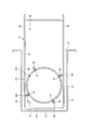
- FIG. 1 is a schematic front view showing a storage tank as a radioactive waste storage container according to an embodiment of the present invention.
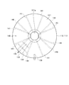
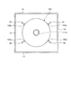
- FIG. 2 is a top view of the storage tank of this embodiment.
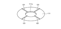
- FIG. 3A is a schematic view of a roof plate constituting the storage tank of the present embodiment.
- FIG. 3-2 is a schematic view of a body plate constituting the storage tank of the present embodiment.
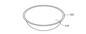
- FIG. 3-3 is a schematic view of the bottom plate constituting the storage tank of this embodiment.
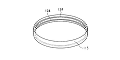
- FIG. 3-4 is a schematic view of the upper part of the skirt constituting the storage tank of the present embodiment.
- FIG. 3-5 is a schematic view of the lower part of the skirt constituting the storage tank of the present embodiment.
- FIG. 4 is a side view showing the first and second steps in the storage tank carry-in method of the present embodiment.
- FIG. 5 is a front view showing the first and second steps.
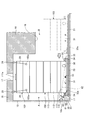
- FIG. 6A is a top view illustrating the first step.
- FIG. 6B is a top view illustrating the first step.
- FIG. 6-3 is a schematic diagram illustrating the first step.
- FIG. 7 is a top view illustrating the second step.
- FIG. 8 is a side view showing a third step in the storage tank carrying-in method of the present embodiment.
- FIG. 9 is a front view illustrating the third step.
- FIG. 10A is a top view illustrating the third step.
- FIG. 10B is a top view illustrating the third step.
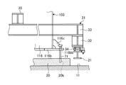
- FIG. 11 is a schematic diagram illustrating the leg portion of the transport carriage and the fourth step.
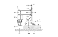
- FIG. 12 is a schematic diagram illustrating the lower tank support portion and the fourth step in the transport carriage.
- FIG. 13 is a side view showing the carrying-out step of the transport carriage in the storage tank carrying-in method of the present embodiment.
- FIG. 14 is a top view illustrating the lower tank installation process.
- FIG. 15 is a schematic diagram illustrating an elevating device for a transport cart.
- FIG. 16 is a side view showing the installation process of the lower tank in the storage tank carrying-in method of the present embodiment.
- FIG. 17 is a side view showing the fifth and sixth steps in the storage tank carrying-in method of the present embodiment.
- FIG. 1 is a schematic front view showing a storage tank as a radioactive waste storage container according to an embodiment of the present invention
- FIG. 2 is a top view of the storage tank of this embodiment
- FIG. Fig. 3-2 is a schematic view of a roof plate constituting the storage tank of this embodiment
- Fig. 3-3 is a bottom plate constituting the storage tank of this embodiment
- 3-4 is a schematic view of the upper part of the skirt constituting the storage tank of the present embodiment
- FIG. 3-5 is a schematic view of the lower part of the skirt constituting the storage tank of the present embodiment
- FIG. 5 is the front view showing the 1st, 2nd process
- FIG. 6-1 is the top view showing the 1st process
- 6B is a top view illustrating the first step
- FIG. 6-3 is a schematic diagram illustrating the first step
- FIG. 7 is a top view illustrating the second step.
- FIG. 8 is a side view showing the third step in the storage tank loading method of the present embodiment
- FIG. 9 is a front view showing the third step
- FIG. 10-1 is a top view showing the third step
- FIG. -2 is a top view showing the third step
- FIG. 11 is a schematic view showing the legs of the transfer carriage and the fourth step
- FIG. 12 is a schematic view showing the support portion of the lower tank and the fourth step in the transfer carriage.
- FIG. 12 is a schematic view showing the support portion of the lower tank and the fourth step in the transfer carriage.
- FIG. 13 is a side view showing the transporting cart unloading process in the storage tank loading method of the present embodiment
- FIG. 14 is a top view showing the lower tank installing process
- FIG. 15 is a schematic diagram showing the transporting cart lifting device.
- FIG. 16 is a side view showing a lower tank installation step in the storage tank carrying-in method of the present embodiment
- FIG. 17 is a side view showing fifth and sixth steps in the storage tank carrying-in method of the present embodiment. It is.
- a storage tank as a radioactive waste storage container of the present embodiment will be described.
- a storage tank (storage container) 101 has an opening in the upper part of a cylindrical main body, the lower part has a dish shape, and can store radioactive waste therein. Is.
- the storage tank 101 is configured by welding an upper tank (upper container) 102 having a cylindrical shape and a lower tank (lower container) 103 having a cylindrical shape by welding.
- the storage tank 101 is configured by joining a roof plate 111, a plurality of trunk plates 112 and 113, a bottom plate 114, and skirts 115 and 116 in order from above.
- the roof plate 111 has a disk shape, and a circular opening 111a is formed at the center. Further, the roof plate 111 has four deflection preventing beams 121 temporarily fixed to the upper surface portion thereof by spot welding, and the deformation during transportation is prevented by the respective deflection preventing beams 121. The deflection preventing beam 121 is removed at the time of assembly.
- the body plates 112 and 113 are one body plate 112 and five body plates 113, and the body plate 112 and the body plate 113 have the same ring shape.
- two round rings 122 are temporarily fixed to the inner peripheral surface portion of the body plates 112 and 113 by spot welding, and the round rings 122 prevent deformation during transportation. The perfect circle ring 122 is removed at the time of assembly.
- the bottom plate 114 has a dish shape as shown in FIG.
- a perfect circle ring 123 is temporarily fixed to the outer peripheral edge portion of the bottom plate 114 by spot welding, and the perfect circle ring 123 prevents deformation during conveyance. The perfect ring 123 is removed at the time of assembly.
- the skirts 115 and 116 are an upper skirt 115 and a lower skirt 116.
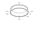
- the skirt upper portion 115 has a ring shape as shown in FIG. 3-4.
- the skirt upper portion 115 has two perfect circle rings 124 temporarily fixed to the inner peripheral surface portion thereof by spot welding, and each perfect circle ring 124 prevents deformation during conveyance.
- the perfect circle ring 124 is removed at the time of assembly.
- the skirt lower portion 116 has a disk-shaped flange portion 116b fixed to the lower portion of the ring-shaped main body 116a by welding, and reinforcing members 116c are welded at equal intervals in the circumferential direction. It is fixed and configured.
- the skirt lower portion 116 has a perfect circle ring 125 temporarily fixed to the inner peripheral surface portion by spot welding, and the perfect circle ring 125 prevents deformation during conveyance. The perfect ring 125 is removed at the time of assembly.
- the storage tank 101 is constructed by joining the roof plate 111, the trunk plates 112 and 113, the bottom plate 114, the skirts 115 and 116, etc. by welding. Then, after these members are joined to form the main body, a discharge pump guide rail 145 (see FIG. 1), which will be described later, is mounted so as to be continuous from the opening 111a.
- one trunk plate 112 and five trunk plates 113 are joined so as to be continuous vertically, and the roof plate 111 is joined to the upper part thereof, and the position of the opening 111a.
- the pump carry-in nozzle 131 is fixed to the base.
- a resin discharge nozzle 133 is attached to the trunk plate 112 via a resin inlet nozzle 132, and the resin discharge nozzle 133 is supported by a support member 134 that is suspended from the roof plate 111.
- the body plate 112 is attached with a cleaning water pipe 136 via a cleaning water inlet nozzle 135, and the cleaning water pipe 136 is supported by a support member 137 suspended from the roof plate 111.
- a nozzle screen 139 is attached to the body plate 112 via an overflow nozzle 138.
- the vent pedestal 140 is attached to the roof plate 111 so as to open to the outside.
- the roof plate 111 has a plurality of support members 141 that radiate on the lower surface and are fixed at equal intervals in the circumferential direction. Further, the roof plate 111 has a top angle 143 fixed thereto.
- the skirt upper portion 115 and the skirt lower portion 116 are joined to each other, and the skirt upper portion 115 is joined to the lower end portion of the body plate 113 and the outer peripheral edge portion of the bottom plate 114 is joined.
- the skirt lower part 116 is provided with a manhole 144.
- a pair of guide rails 145 are arranged along the axial centers of the roof plate 111, the trunk plates 112 and 113, the bottom plate 114, and the skirts 115 and 116, and are continuous with the opening 111a, and a plurality of support members. 146 is supported by the body plate 113.
- a storage tank installation area is provided in an underground portion of the building. For this reason, after manufacturing a component that divides the storage tank at a factory on another site, it is transported to the building by a truck, etc., and the multiple members are carried from the entrance of the building and pass through a predetermined passage or opening. To the storage tank installation area.
- the roof plate 111, the plurality of trunk plates 112, 113, the bottom plate 114, the skirts 115, 116, and the like constituting the storage tank 101 are transported to the carry-in area before the installation area, and the roof plate 111 and the trunk plate 112 are conveyed.
- the upper tank 102 is manufactured by joining the three body plates 113
- the lower tank 103 is manufactured by joining the two body plates 113, the bottom plate 114, and the skirts 115 and 116. And it carries in to an installation area in order of the upper tank 102 and the lower tank 103, and joins both.
- the lower tank 103 is manufactured by joining the body plate 113, the bottom plate 114, and the skirts 115, 116 while carrying in the area where the upper tank 102 is installed.
- the carry-in port 16 to the installation area A is set to be lower than the total height of the storage tank 101 (the height at which the upper tank 102 and the lower tank 103 are joined), and the upper tank 102 and the lower tank 103 It is set higher than each height. That is, in the installation area A, vertical walls 12, 13, and 14 are erected on three sides, and a vertical wall 18 is also provided on the carry-in entrance 16 side.
- a loading area B is provided adjacent to the loading port 16 side in the installation area A.
- the method for carrying in the radioactive waste storage tank is a method for carrying the storage tank 101 from the loading area B into the installation area A, and the upper tank 102 is horizontally disposed along the floor surface 11 from the loading port 16.
- a first step of transferring and carrying into the installation area A a second step of transferring the upper tank 102 carried into the installation area A upward, and a lower tank 103 horizontally from the carry-in entrance 16 along the floor surface 11
- the lower tank 103 is mounted on a transport cart, and the transport cart travels on the floor surface 11 so that the lower tank 103 is carried into the installation area A, and is lifted and lowered by the lifting device disposed on the floor surface 11. After being lifted and transported from the installation area A, it is lowered by the lifting device and installed on the foundation.
- the side surface of the lower tank 103 is supported by the transport cart, and is carried into the installation area A by the travel of the transport cart.
- the lower tank 103 is positioned by a positioning device at a predetermined position below the upper tank 102.
- the lower tank 103 is installed on the foundation and then fixed to the foundation with foundation bolts, and then the upper tank 102 is placed.
- a guide rail 145 for the discharge pump is attached so as to continue from the opening 111a.
- the first transport carriage 22 which is a transport carriage carries the upper tank 102 from the carry-in area B to the installation area A.
- the first transport carriage 22 includes two vertical beams 23 having two I-shaped cross sections parallel to the guide rail 21 and four horizontal beams 24 connecting the vertical beams 23 orthogonal to the guide rail 21 and having two I-shaped cross sections. It consists of and.
- Each vertical beam 23 has an upper surface portion connected to an end portion of the horizontal beam 24 and a lower surface portion mounted with a plurality of guide rollers 25 that roll on the guide rail 21.
- the vertical beam 23 and the horizontal beam 24 constitute a frame
- the vertical beam 23, the horizontal beam 24, and the guide roller 25 constitute a cart body. Accordingly, the first transport carriage 22 can mount the upper tank 102 on each cross beam 24, and moves from the loading area B to the installation area A along the guide rail 21, so that the upper tank 102 is brought into the carry-in port. 16 can be carried into installation area A.
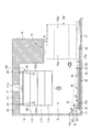
- the first transport carriage 22 is movably provided by a moving device 61 as shown in FIGS.
- the moving device 61 pulls the bogie main body, and includes a cable member 62 and a pulling mechanism 63.
- the rope member 62 is hung between the carriage main body on the moving side and the vertical wall 12 on the fixed side, and includes, for example, a chain.
- the cable member 62 is connected at one end to a support piece 23a as an attachment member provided on the side of the longitudinal beam 23 of the carriage body, and is attached to the wall 12 as a support piece as an attachment member. The other end is connected to 12a.
- the traction mechanism 63 shortens or extends the length of the rope member 62 and is configured as a so-called lever block (registered trademark), and shortens the length of the rope member 62 by operating the lever.
- the moving device 61 is provided on both sides of the carriage main body corresponding to each vertical beam 23 of the carriage main body, and the first conveying carriage 22 is installed by operating both simultaneously to shorten the length of each cord member 62. Tow to area A side.
- the other end of the rope member 62 is connected to a support piece (not shown) as an attachment member provided on the floor surface 11 on the carry-in area B side. By shortening, the 1st conveyance trolley 22 is pulled to the area B for carrying in.
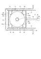
- the first transport carriage 22 may be provided so as to be movable by a moving device 65 as shown in FIG. 6-2.
- the moving device 65 pushes out the main body of the carriage and has an extrusion mechanism.
- the push-out mechanism is configured as, for example, a hydraulic actuator, and is disposed between the carriage main body on the moving side and the floor surface 11 on the fixed side.
- the push-out mechanism as a hydraulic actuator has a hydraulic cylinder 66 and a rod 67 connected to a piston in the hydraulic cylinder 66.
- the mounting member is provided on the side of the transverse beam 24 of the carriage body.
- the tip of the rod 67 is connected to the support piece 24a as a support, and the hydraulic cylinder 66 is connected to a support piece (not shown) as an attachment member provided on the floor surface 11.
- the moving device 65 pushes the first transport carriage 22 to the installation area A side when hydraulic oil is sent to the hydraulic cylinder 66 and the rod 67 extends.
- the moving device 65 sends the hydraulic oil to the hydraulic cylinder 66 and shortens the rod 67 so that the first transport carriage 22 is pulled back to the loading area B side.
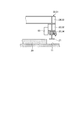
- the first transport carriage 22 may be provided so as to be movable by a moving device 69 as shown in FIG. 6-3.
- the moving device 69 travels the carriage body and has a drive mechanism.
- the drive mechanism is configured as a rotational drive mechanism such as a motor, for example, and is coupled to the guide roller 25 to roll the guide roller 25.
- the moving apparatus 69 moves the 1st conveyance trolley 22 to the installation area A side by rolling the guide roller 25 to one direction with the drive mechanism of the moving apparatus 69.
- the moving device 69 moves the first transport carriage 22 to the loading area B side by rolling the guide roller 25 in the other direction by the drive mechanism of the moving device 69.
- the upper tank 102 has four suspension pieces 102a fixed to the outer peripheral portion at equal intervals in the circumferential direction in advance. Accordingly, the four suspension chains 29 are locked from the suspension pieces 28 to the suspension pieces 102a of the upper tank 102, and the suspension chain 29 is pulled by a chain block (not shown), whereby the upper tank 102 is passed through the suspension chain 29. Can be lifted and transferred upward.
- the second transport cart 31 as a transport cart carries the lower tank 103 from the carry-in area B to the installation area A.
- the second transport carriage 31 has two I-shaped cross sections orthogonal to the guide rail 21 and vertical beams 32 having two I-shaped cross sections parallel to the guide rail 21 in substantially the same manner as the first transport carriage 22. It consists of two horizontal beams 33 that connect the vertical beams 32.
- Each vertical beam 32 has an end portion of the horizontal beam 33 connected to the upper surface portion of each end portion, and a plurality of guide rollers 34 that roll on the guide rail 21 are mounted on the lower surface portion.
- the vertical beam 32 and the horizontal beam 33 constitute a frame
- the vertical beam 32, the horizontal beam 33, and the guide roller 34 constitute a cart body.
- the second transport cart 31 is provided so as to be movable by a moving device 61.
- the moving device 61 pulls the bogie main body, and includes a cable member 62 and a pulling mechanism 63.
- the rope member 62 is hung between the carriage main body on the moving side and the vertical wall 12 on the fixed side, and includes, for example, a chain.
- the cable member 62 is connected at one end to a support piece 32a as an attachment member provided on the side of the longitudinal beam 32 of the carriage body, and is attached to the wall 12 as a support piece as an attachment member. The other end is connected to 12a.
- the traction mechanism 63 shortens or extends the length of the rope member 62 and is configured as a so-called lever block (registered trademark), and shortens the length of the rope member 62 by operating the lever.
- the moving device 61 is provided on both sides of the carriage main body corresponding to each vertical beam 32 of the carriage main body, and the second transport carriage 31 is installed by operating both simultaneously to shorten the length of each cord member 62. Tow to area A side.
- the other end of the rope member 62 is connected to a support piece (not shown) as an attachment member provided on the floor surface 11 on the carry-in area B side. By shortening, the 2nd conveyance trolley 31 is pulled to the area B for carrying in.
- the second transport carriage 31 may be provided so as to be movable by a moving device 65.
- the moving device 65 pushes out the main body of the carriage and has an extrusion mechanism.
- the push-out mechanism is configured as, for example, a hydraulic actuator, and is disposed between the carriage main body on the moving side and the floor surface 11 on the fixed side.
- the push-out mechanism as a hydraulic actuator has a hydraulic cylinder 66 and a rod 67 connected to a piston in the hydraulic cylinder 66.
- the mounting member is provided on the side of the transverse beam 33 of the carriage body.
- the tip of the rod 67 is connected to the support piece 33 a as a support, and the hydraulic cylinder 66 is connected to a support piece (not shown) as an attachment member provided on the floor surface 11.
- the moving device 65 pushes the second transport carriage 31 to the installation area A side when hydraulic oil is sent to the hydraulic cylinder 66 and the rod 67 extends.
- the moving device 65 pulls back the second transport carriage 31 to the loading area B side when the hydraulic oil is sent to the hydraulic cylinder 66 and the rod 67 expands and contracts.
- the second transport carriage 31 may be provided so as to be movable by a moving device 69 as shown in FIG. 6-3.
- the moving device 69 travels the carriage body and has a drive mechanism.
- the drive mechanism is configured as a rotation drive mechanism such as a motor, for example, and is connected to the guide roller 34 to roll the guide roller 34.
- the moving apparatus 69 moves the 2nd conveyance trolley 31 to the installation area A side by rolling the guide roller 34 to one direction with the drive mechanism of the moving apparatus 69.
- the moving device 69 moves the second transport carriage 31 to the loading area B side by rolling the guide roller 34 in the other direction by the drive mechanism of the moving device 69.
- the second transport carriage 31 is provided with a first support member 35 capable of supporting the side portion of the lower tank 103 at the middle portion of each longitudinal beam 32 and each transverse beam 33 in the longitudinal direction.
- the first support member 35 has an I-shaped cross section, and is disposed along a horizontal direction orthogonal to each vertical beam 32 and each horizontal beam 33, and one end portion is bolted to the upper surface of each vertical beam 32 and each horizontal beam 33. It is connected and the other end is extended toward the inside of the frame.
- the mounting height of the first support member 35 is different between the vertical beam 32 and the horizontal beam 33.
- the first support member 35 provided on the vertical beam 32 is connected on the vertical beam 32 and mounted at the same height as the horizontal beam 33.
- the first support member 35 provided on the cross beam 33 is connected to the cross beam 33.
- the second transport carriage 31 has a plurality of first support pads 36 fixed to the side of the lower tank 103 at equal intervals in the circumferential direction.
- the first support pad 36 has a curved surface such that one surface is in close contact with the outer peripheral surface of the lower tank 103, the other surface is a horizontal surface, and is in close contact with the outer peripheral surface of the lower tank 103.
- welding or , Bolts
- each first support pad 36 is a lower portion corresponding to the mounting height of each first support member 35. It is fixed at the position of the tank 103.
- each first support member 35 has a plurality of mounting through holes formed in a support plate 35a integrally formed at the end, while each first support pad 36 has a mounting plate.
- a plurality of female screw portions are formed.
- the second transport carriage 31 has the lower tank 103 disposed inside the frame body, and the support plates 35a of the first support members 35 are placed in the lower tanks 103 at positions raised from the floor 11 by a predetermined amount.
- the lower tank 103 can be detachably supported by being in close contact with the first support pad 36 and attaching the first support members 35 to the first support pads 36 with a plurality of fixing bolts 37.
- this 2nd conveyance trolley 31 can support the lower tank 103 by each vertical beam 32 and each horizontal beam 33, and it moves to the installation area A from the carrying-in area B along the guide rail 21,
- the lower tank 103 can be carried into the installation area A from the carry-in port 16.
- the lower tank 103 is provided with an insertion hole 116bb in the flange portion 116b.
- the positioning pin 71 is inserted with the tip directed downward.
- the positioning hole 20b is formed in the foundation 20.
- the positioning hole portion 20 b is inserted with the tip of the positioning pin 71 when the lower tank 103 is transferred to a predetermined position below the upper tank 102.
- the predetermined position below the upper tank 102 is the installation area A, and is a position where the lower tank 103 is fixed to the foundation with a foundation bolt.
- the positioning hole portion 20b is formed at the base of the position vertically below the insertion hole 116bb provided in the flange portion 116b of the lower tank 103. Therefore, when the lower tank 103 is transferred to a predetermined position below the upper tank 102, the tip of the positioning pin 71 inserted through the insertion hole 116bb is inserted into the positioning hole portion 20b. Therefore, when the tip of the positioning pin 71 is inserted into the positioning hole 20b, the lower tank 103 is positioned at a position where it is fixed to the foundation with the foundation bolt.
- the insertion hole 116bb, the positioning pin 71, and the positioning hole portion 20b constitute a positioning device.
- the foundation bolt 51 is used as the positioning pin 71
- the attachment bolt 116ba through which the foundation bolt 51 penetrates the flange portion 116b of the lower tank 103 is used as the insertion hole 116bb
- the foundation bolt 51 is screwed together.
- the positioning device may be configured with the female screw portion 20a of the foundation 20 as the positioning hole portion 20b.
- the lower tank 103 is provided with a plurality of second support pads 41 at equal intervals in the circumferential direction on the side, and the second support pads 41 are provided with second support members. 42 is detachably attached by a fixing bolt 43. That is, the second support pad 41 has a curved surface such that one surface is in close contact with the outer peripheral surface of the lower tank 103, the other surface is a horizontal surface, and is in close contact with the outer peripheral surface of the lower tank 103. Or, it is fixed by bolts).
- the second support pad 41 is fixed at a position that is substantially the same height as the first support pad 36 fixed to the vertical beam 32 described above and is shifted by about 30 degrees in the circumferential direction of the lower tank 103. Yes.
- Each second support member 42 has an I-shaped cross section, is disposed along the radial direction of the lower tank 103, and a support plate 42 a provided at one end is in close contact with each second support pad 41 of the lower tank 103.
- the plurality of fixing bolts 43 pass through the support plate 42 a and are screwed into the second support pads 41, so that the second support members 42 are attached to the lower tank 103 via the second support pads 41. .
- the jack 44 as a lifting device has a piston 44 a that can be lifted and lowered by electric power (or hydraulic pressure), and is disposed on the floor surface 11 corresponding to the other end of each second support member 42. Therefore, each second support member 42 is fixed at a predetermined position with respect to the lower tank 103 carried into the installation area A from the carry-in area B by the second transport carriage 31, and the second support members 42
- the lower tank 103 can be raised through the second support members 42 by disposing the jacks 44 below and operating the jacks 44 to advance the pistons 44a.
- the load of the lower tank 103 is received by inserting the several liner plate 45 between the foundation 20 and the flange part 116b of the lower tank 103.
- the transport cart 31 can be carried out from the installation area A to the carrying-in area B. Then, after raising the lower tank 103 using the jack 44, the liner plate 45 is removed, and the lower tank 103 is lowered via each second support member 42 by operating the jack 44 and retracting each piston. And can be placed on the foundation 20.
- the roof plate 111, the plurality of trunk plates 112, 113, the bottom plate 114, the skirts 115, 116, and the like constituting the storage tank 101 are manufactured in a factory and conveyed to a building by a truck, As shown in FIGS. 4 to 7, the building is transported from the entrance of the building to a loading area B before the installation area A through a predetermined passage. And in this carrying-in area B, the upper tank 102 is manufactured by joining the roof board 111, the trunk board 112, and the three trunk boards 113.
- FIG. 1 the roof plate 111, the plurality of trunk plates 112, 113, the bottom plate 114, the skirts 115, 116, and the like constituting the storage tank 101 are manufactured in a factory and conveyed to a building by a truck, As shown in FIGS. 4 to 7, the building is transported from the entrance of the building to a loading area B before the installation area A through a predetermined passage. And in this carrying-in area B, the upper tank 102 is manufactured by joining
- the upper tank 102 When the upper tank 102 is manufactured, the upper tank 102 is placed on the first transport carriage 22 supported by the guide rail 21 in the loading area B. And it moves to the installation area A from the carrying-in area B by advancing the 1st conveyance trolley 22 with the moving apparatus 61 (65,69). In this case, even if the height of the carry-in port 16 is not sufficient, first, only the upper tank 102 is carried into the installation area A from the carry-in port 16 by the first transfer carriage 22, so that the work for carrying in the upper tank 102 is performed. Becomes easy.
- each suspension chain 29 suspended from each suspension piece 28 provided on the ceiling 15 is connected to each suspension piece 102 a of the upper tank 102.
- the upper tank 102 is lifted and transferred upward by pulling the suspension chain 29 by the chain block.
- the two body plates 113, the bottom plate 114, and the skirts 115 and 116 are joined in the carrying-in area B during the operation of transferring the upper tank 102 upward.
- the lower tank 103 is manufactured.
- the second transport carriage 31 is prepared in the carry-in area B, and the lower tank 103 is placed inside the frame. Is fixed to each first support pad 36 of the lower tank 103 at a position where it is raised by a predetermined amount from the floor surface 11, so that the second transport cart 31 is attached to the first support pad 36 of the lower tank 103.
- the lower tank 103 is supported. Then, the supported lower tank 103 is installed from the carry-in entrance 16 by moving the second transport carriage 31 from the carry-in area B to the installation area A along the guide rail 21 by the moving device 61 (65, 69). Can be brought into Zone A.
- the lower tank 103 is positioned below the upper tank 102, and a predetermined gap is secured between them.
- the position determination is made so as to be inserted into the insertion hole 116bb provided in the flange portion 116b of the lower tank 103.
- the pin 71 moves together with the lower tank 103 while contacting the upper surface of the foundation 20. Then, when the lower tank 103 is transferred to a predetermined position fixed to the foundation by the foundation bolt, the positioning pin 71 is inserted into the positioning hole 20b provided in the foundation 20, and the lower tank 103 is positioned.
- the lower tank 103 When the lower tank 103 is carried into the installation area A together with the second transfer carriage 31, the lower tank 103 is supported by the second transfer carriage 31 in the installation area A as shown in FIGS.
- the second support members 42 are fixed to the second support pads 41 of the lower tank 103, and the jacks 44 are arranged below the second support members 42. Then, by operating each jack 44, the lower tank 103 is raised via each second support member 42. At this time, the load of the lower tank 103 is received by inserting a plurality of liner plates 45 between the foundation 20 and the flange portion 116 b of the lower tank 103.
- the first support pads 36 are removed from the first support members 35 of the lower tank 103 by loosening the fixing bolts 37. Subsequently, after removing only the lateral beam 33 on the wall 12 side from the second transport carriage 31, the second transport carriage 31 is moved to be carried out from the installation area A to the loading area B.
- the lower tank 103 when the lower tank 103 is supported by the second transport carriage 31 in the carry-in area B, the lower tank 103 is raised.
- the lower tank 103 may be raised using the jack 44, and at this time, the second support member 42 is fixed to each second support pad 41 of the lower tank 103, and each jack 44 The lower tank 103 may be raised through the second support members 42.
- you may prepare a suspension chain, a lifting equipment, etc. separately.
- the jack 44 is operated to raise the lower tank 103 via the second support member 42, and in this state, the connection between the lower tank 103 and the first support member 35 is released and the second transport carriage 31 is carried out. To do. In this case, the jack 44 is actuated a little to support the lower tank 103 via the second support member 42 at the position where the second transport carriage 31 supports the lower tank 103. The lower tank 103 is supported, and the connection between the lower tank 103 and the first support member 35 may be released.
- the lower tank 103 When the second transport carriage 31 is unloaded from the installation area A to the loading area B, as shown in FIG. 16, the lower tank 103 is then lifted using the jack 44, and then the liner plate 45 is removed. Then, the lower tank 103 is lowered via the second support members 42 and placed on the foundation 20 by operating the jacks 44 to retract the pistons 44a.
- positioning of the lower tank 103 in the horizontal direction is performed on the foundation 20, and as shown in FIG. 15, the foundation bolt 51 is inserted into the plurality of mounting holes 116 ba provided in the flange portion 116 b of the lower tank 103 from above.
- the lower tank 103 is fixed on the foundation 20 by passing through and screwing into a female screw portion 20a configured by arranging a nut on the foundation 20 in advance.
- the upper chain 102 is suspended and moved downward by moving the suspension chain 29 by the chain block, and the upper tank 102 is placed on the lower tank 103. And the lower edge part of the upper tank 102 and the upper edge part of the lower tank 103 are welded and joined (welded part J). Then, the suspension chain 29 is removed from the upper tank 102.
- the guide rails 145 for the discharge pump are arranged so as to continue to the inside from the opening 111a, and are supported on the body plate 113 by the plurality of support members 146.
- the radioactive waste storage tank 101 having the opening 111a at the top of the main body and storing radioactive waste therein is carried into the installation area A.
- the first transfer carriage 22 and the second transfer carriage 31 are provided so as to be movable by the moving devices 61, 65, 69, the large storage tank 101 can be easily carried into a predetermined position.
- the moving device 61 pulls the first transport cart 22 and the second transport cart 31, and the first transport cart 22 and the second transport cart 31 are Supporting pieces 23 a and 32 a capable of connecting the cable member 62 for towing in the moving device 61 are provided. Accordingly, the first transport cart 22 and the second transport cart 31 can be moved by the cable member 62 of the moving device 61 being attached, so that the large storage tank 101 can be easily carried into a predetermined position.
- the moving device 65 pushes out the first transport cart 22 and the second transport cart 31, and the first transport cart 22 and the second transport cart 31 move.
- An attachment member capable of connecting the extrusion mechanism in the device 65 is provided. Accordingly, since the first transfer carriage 22 and the second transfer carriage 31 are movable with the push-out mechanism of the moving device 65 attached, the large storage tank 101 can be easily carried into a predetermined position.
- the moving device 69 causes the first transport cart 22 and the second transport cart 31 to travel, and the first transport cart 22 and the second transport cart 31 are: Guide rollers 25 and 34 that are rolled by a driving mechanism in the moving device 69 are provided. Accordingly, the first transport carriage 22 and the second transport carriage 31 can be moved when the drive mechanism of the moving device 69 is attached and the guide rollers 25 and 34 are rolled. Can be easily brought into position.
- the first support member is connected to the second transport cart 31 at one end and can support the side of the lower tank 103 constituting the storage tank 101 at the other end. 35 is provided. Therefore, since the second transport carriage 31 supports the side portion of the lower tank 103 via the plurality of first support members 35, the lower tank 103 can be transported in a low posture, and a large storage tank 101 can be easily installed at a predetermined position.
- the ends of the pair of horizontal beams 32 and the beams 33 are connected to form a frame on which the lower tank 103 can be arranged.
- a second transport cart 31 is formed, and a first support member 35 is connected to the vertical beam 32 and the horizontal beam 33. Therefore, by disposing the lower tank 103 inside the frame and supporting it by the first support member 35, the lower tank 103 is transported from the floor 11 with a minute gap regardless of the height of the second transport carriage 31. Even when the carry-in port 16 is small with respect to the installation area A, the lower tank 103 can be easily carried in and installed.
- the first support member 35 is connected to the longitudinal intermediate portions of the vertical beams 32 and the horizontal beams 33, respectively. Therefore, the length of the first support member 35 can be shortened by reducing the distance between each vertical beam 32 and each horizontal beam 33 and the lower tank 103, and the load acting on the first support member 35 can be reduced. The first support member 35 can be reduced in size and weight.
- a plurality of first support pads 36 fixed at equal intervals in the circumferential direction are provided on the side of the lower tank 103, and the end of the first support member 35 is connected to the first support member 35. 1 is detachably connected to the side of the lower tank 103 via a support pad 36. Therefore, by fixing the first support pad 36 to the side of the lower tank 103 in advance, the first support member 35 and the first support pad 36 are connected to support the lower tank 103 easily. Can do.
- the storage container transport cart of the present embodiment is provided with a female screw portion into which a fixing bolt 37 for fixing the first support member 35 is screwed to the first support pad 36. Therefore, it is possible to simplify the connection work between the first support member 35 and the first support pad 36.
- the storage tank 101 of the radioactive waste which has the opening part 111a in the upper part of a main body and can store radioactive waste inside is carried in to the installation area A.
- the storage container loading method includes a first step of horizontally transferring the upper tank 102 from the carry-in entrance 16 along the floor surface 11 and carrying it into the installation area A, and an upper tank 102 carried into the installation area A.
- a second step of transferring upward a third step of transferring the lower tank 103 horizontally from the carry-in entrance 16 along the floor 11 and carrying it below the upper tank 102 in the installation area A, and the lower tank 103 as the upper tank
- a fourth step of positioning at a predetermined position below 102 a fifth step of transferring the upper tank 102 downward and placing it on the lower tank 103, and joining the upper tank 102 and the lower tank 103 together
- a sixth step is
- the lower tank 103 is carried from the carry-in port 16 below the upper tank 102, and the upper tank 102 is placed on the lower tank 103. Even when the carry-in port 16 is small with respect to the installation area A where the storage tank 101 is installed, the storage tank 101 can be easily carried in and installed by mounting and joining the two. Moreover, by positioning the lower tank 103 at a predetermined position below the upper tank 102, the lower tank 103 can be installed at a predetermined position in the installation area A.
- the step of positioning the lower tank 103 at a predetermined position below the upper tank 102 is a positioning pin that is disposed with the tip facing downward and transferred together with the lower tank 103. 71 and a positioning hole 20b provided on the floor surface 11 side so that the tip of the positioning pin 71 can be inserted, and when the lower tank 103 is transferred to a predetermined position below the upper tank 102 The tip of the positioning pin 71 is inserted into the positioning hole 20b. Accordingly, by inserting the positioning pin 71 into the positioning hole 20b, the lower tank 103 can be positioned at a predetermined position below the upper tank 102, and the lower tank 103 is installed at a predetermined position in the installation area A. Can do.
- the step of horizontally transferring the lower tank 103 from the side entrance portion along the floor surface 11 and loading it below the upper tank 102 in the installation area A is performed by the lower tank 103.
- the second transport carriage 31 is horizontally transferred along the floor surface 11 by pulling the cable member 62 attached to the second transport carriage 31 on which the stool is mounted between the fixed member and the cable member 62. Therefore, by providing the second transport carriage 31 so as to be movable, the large storage tank 101 can be easily carried into a predetermined position.
- the lower tank 103 is mounted on the second transport carriage 31 and travels along the guide rail 21 so as to be carried into the installation area A and disposed on the floor surface 11. After being lifted by the jack 44 and unloading the second transport carriage 31 from the installation area A, it is lowered by the jack 44 and installed on the foundation 20. Therefore, the second transfer carriage 31 can be easily carried out by placing the lower tank 103 on the second transfer carriage 31 and carrying the lower tank 103 into the installation area A and raising the lower tank 103 by the jack 44.
- the side surface portion of the lower tank 103 is supported by the second transport carriage 31 and carried into the installation area A by the travel of the second transport carriage 31. Accordingly, the second transport cart 31 supports the side surface of the lower tank 103 and carries it into the installation area A, so that the height of the lower tank 103 supported by the second transport cart 31 can be kept low. The transportability of the tank 103 can be improved.
- the lower tank 103 is installed on the foundation 20 and then fixed to the foundation 20 with a plurality of foundation bolts 51, and then the upper tank 102 is placed on the lower tank 103. is doing. Accordingly, by mounting the upper tank 102 after fixing the lower tank 103 to the foundation 20, the lower tank 103 can be fixed at an appropriate position in a lightweight state, and by the mounting work of the upper tank 102. The position shift of the lower tank 103 can be prevented.
- the upper tank 102 and the lower tank 103 are joined, they are mounted on the guide rail 145 for the discharge pump so as to continue from the opening 111a. Therefore, by attaching the guide rail 145 after the assembly of the main body, it is possible to improve the assembling performance without dividing the guide rail 145.
- the upper tank 102 is constituted by a roof plate 111 and a plurality of trunk plates 112 and 113
- the lower tank 103 is constituted by a plurality of trunk plates 113, a bottom plate 114, and skirts 115 and 116.
- the roof plate 111, the plurality of trunk plates 112, 113, the bottom plate 114, and the skirts 115, 116 are carried to the loading area B through the passage from the entrance of the building.
- the roof plate 111 and the plurality of trunk plates 112, 113 are joined to form the upper tank 102, and a plurality of body plates 113, a bottom plate 114, and skirts 115, 116 are joined to constitute the lower tank 103, and the upper tank 102 and the lower tank 103 are arranged in this order.
- the storage tank 101 is composed of a plurality of parts including the roof plate 111, the trunk plates 112 and 113, the bottom plate 114, and the skirts 115 and 116, so that the storage tank 101 can be easily transported even in a narrow passage. Can be improved.
- the carry-in port 16 to the installation area A is set to be lower than the total height of the storage tank 101 (the height at which the upper tank 102 and the lower tank 103 are joined), In addition, the height of each of the upper tank 102 and the lower tank 103 is set higher. Therefore, even when the height of the carry-in port 16 with respect to the installation area A where the storage tank 101 is installed is defined, the storage tank 101 can be easily carried into the installation area A and installed.
- the cylindrical body has an opening 111a in the upper part, the lower part has a dish shape, and the radioactive waste can be stored therein.
- a waste storage tank 101 is formed by joining a cylindrical upper tank 102 and a lower tank 103 by welding.
- the radioactive waste storage container of the present embodiment is one in which the upper tank 102 and the lower tank 103 are joined by transferring the lower tank 103 below the upper tank 102 while the upper tank 102 is transferred upward.
- the lower tank 103 is provided with a positioning pin 71 arranged with its tip facing downward, and when it is transferred to a predetermined position below the upper tank 102, a positioning hole is provided on the floor 11 side. The tip of the positioning pin 71 is inserted into the portion 20b.
- the storage tank 101 is formed by bringing the tank into the installation area A in the state of the small upper tank 102 and the lower tank 103, and the upper tank 102 and the lower tank 103 are joined to form a large storage tank. 101 can be carried in easily.
- the positioning pin 71 into the positioning hole 20b, the lower tank 103 can be positioned at a predetermined position below the upper tank 102, and the lower tank 103 is installed at a predetermined position in the installation area A. Can do.
- the roof plate 111 having the opening 111a, the plurality of ring-shaped trunk plates 112 and 113, the bottom plate 114 having a dish shape, and the bottom plate 114 are supported.
- the storage tank 101 is configured by combining and joining the skirts 115 and 116 to be sequentially combined. Therefore, by comprising a plurality of parts including the roof plate 111, the trunk plates 112 and 113, the bottom plate 114, and the skirts 115 and 116, even a narrow passage can be easily transported and the assemblability can be improved. Can do.
- each part is formed in a ring shape and transported so as not to be deformed, thereby facilitating assembly work in the carry-in area B, and can be easily carried into the installation area A and joined in a short period of time.
- the roof plate 111, the plurality of trunk plates 112, 113, the bottom plate 114, and the skirts 115, 116 are joined to each other so as to continue from the opening 111a.
- a guide rail 145 for the discharge pump is mounted. Therefore, by attaching the guide rail 145 after the assembly of the main body, it is possible to improve the assembling performance without dividing the guide rail 145.
- the storage tank 101 is configured by joining ten parts such as the roof plate 111, the plurality of trunk plates 112 and 113, the bottom plate 114, and the skirts 115 and 116. Is not limited to the examples.
- the storage tank 101 is an upper tank 102 and a lower tank 103, and is sequentially carried into the installation area A.
- the number of divisions at this time is not limited to two, and an upper tank, a middle tank, a lower tank, etc. It may be divided into three or four or more.
- the storage tank 101 is carried into the installation area A.
- the storage tank 101 is carried out from the installation area A to the carrying-in area B.
- the storage tank 101 is divided into an upper tank 102 and a lower tank 103, and the storage tank 101 is carried out in the reverse procedure.
- the 1st conveyance trolley 22 and the 2nd conveyance trolley 31 are transferred to the area B for carrying in from the installation area A by the moving apparatus 61 (65,69).
Landscapes
- Engineering & Computer Science (AREA)
- Mechanical Engineering (AREA)
- Environmental & Geological Engineering (AREA)
- Physics & Mathematics (AREA)
- General Engineering & Computer Science (AREA)
- High Energy & Nuclear Physics (AREA)
- Transportation (AREA)
- Platform Screen Doors And Railroad Systems (AREA)
- Processing Of Solid Wastes (AREA)
Abstract
貯蔵容器の搬送台車において、所定の位置に容易に搬入可能とする。 本体の上部に開口部(111a)を有して内部に放射性廃棄物を貯留可能な放射性廃棄物の貯蔵タンク(101)を設置区域(A)に搬入する貯蔵容器の搬送台車であって、床面(11)に沿って移動自在な第1搬送台車(22)及び第2搬送台車(31)と、第1搬送台車(22)及び第2搬送台車(31)を移動可能にする移動装置(61)とを備える。
Description
本発明は、各種プラントにて、放射性廃棄物の貯蔵容器を所定の場所に搬入する貯蔵容器の搬送台車及び貯蔵容器の搬入方法並びに放射性廃棄物の貯蔵容器に関するものである。
従来、例えば、放射性廃棄物の貯蔵設備は、放射性フィルタスラッジや放射性廃棄イオン交換樹脂などの放射性廃棄物を、含水状態で長期間貯蔵するための貯蔵設備であって、タンク内に一定期間貯蔵された放射性廃棄物を安全かつ容易に取り出すことを目的としている。貯蔵設備は、放射線遮蔽壁で囲まれた空間内にタンクが設置されている。タンクは、その内部に、鉛直線上に位置するガイドレールが設けられている。前記空間における天上側の放射線遮蔽壁は、上端開口部が設けられ、当該開口部が放射線遮蔽材で作られたプラグ状の蓋によって閉じられている。
このような放射性廃棄物を貯蔵する貯蔵タンクとしては、下記特許文献1及び特許文献2に記載されたものがある。この特許文献1に記載された放射性廃棄物の貯蔵・移送装置は、放射性廃棄物を貯える大気開放容器と、この容器の遮蔽水中に入れられる攪拌移送ポンプと、ポンプに接続した移送管とを有し、放射性廃棄物と遮蔽水とを攪拌混合した後に移送管より排出するものである。また、特許文献2に記載された放射性廃棄物の貯蔵容器は、円筒形状をなす上部容器と下部容器が溶接により接合されて構成されるものである。
なお、特許文献2には、貯蔵容器の搬入方法として本体の上部に開口部を有して内部に放射性廃棄物を貯留可能な放射性廃棄物の貯蔵容器を所定の区域に搬入する貯蔵容器の搬入方法であって、上部容器を側方入口部から水平移送して前記区域に搬入する工程と、前記区域内に搬入された前記上部容器を上方に移送する工程と、下部容器を前記側方入口部から水平移送して前記区域における前記上部容器の下方に搬入する工程と、前記上部容器を下方に移送して前記下部容器の上に載置する工程と、前記上部容器と前記下部容器を接合する工程と、を有することが示されている。
また、下記特許文献3には、本体の上部に開口部を有して内部に放射性廃棄物を貯留可能な放射性廃棄物の貯蔵容器を所定の区域に搬入する貯蔵容器の搬送台車であって、床面に沿って移動自在な台車本体と、一端部が前記台車本体に連結されて他端部が前記貯蔵容器の側部を支持可能なサポート部材と、を備えることが示されている。
ところで、放射性廃棄物の貯蔵タンクは、放射能を帯びている樹脂を貯蔵するものであることから、建屋の地下で、コンクリート壁により遮蔽された部屋内に設置する必要がある。しかし、この放射性廃棄物の貯蔵タンクは、大型の容器であることから、建屋の地下室に搬入することが困難である。
本発明は、上述した課題を解決するものであり、所定の位置に容易に搬入可能とする貯蔵容器の搬送台車及び貯蔵容器の搬入方法並びに放射性廃棄物の貯蔵容器を提供することを目的とする。
上記の目的を達成するための本発明の貯蔵容器の搬送台車は、本体の上部に開口部を有して内部に放射性廃棄物を貯留可能な放射性廃棄物の貯蔵容器を所定の区域に搬入する貯蔵容器の搬送台車であって、床面に沿って移動自在な台車本体と、前記台車本体を移動可能にする移動装置と、を備えることを特徴とする。
従って、搬送台車が移動装置により移動可能に設けられていることで、大型の貯蔵容器を所定の位置に容易に搬入することができる。
本発明の貯蔵容器の搬送台車では、前記移動装置は、前記台車本体を牽引するものであって、前記台車本体は、前記移動装置における牽引用の索部材を連結可能な取付部材が設けられていることを特徴とする。
従って、搬送台車は、移動装置の索部材が取付けられて移動可能となるため、大型の貯蔵容器を所定の位置に容易に搬入することができる。
本発明の貯蔵容器の搬送台車では、前記移動装置は、前記台車本体を押し出すものであって、前記台車本体は、前記移動装置における押出機構を連結可能な取付部材が設けられていることを特徴とする。
従って、搬送台車は、移動装置の押出機構が取付けられて移動可能となるため、大型の貯蔵容器を所定の位置に容易に搬入することができる。
本発明の貯蔵容器の搬送台車では、前記移動装置は、前記台車本体を走行させるものであって、前記台車本体は、前記移動装置における駆動機構により転動されるガイドローラが設けられていることを特徴とする。
従って、搬送台車は、移動装置の駆動機構が取付けられガイドローラが転動されることで移動可能となるため、大型の貯蔵容器を所定の位置に容易に搬入することができる。
本発明の貯蔵容器の搬送台車では、一端部が前記台車本体に連結されて他端部が前記貯蔵容器の側部を支持可能なサポート部材を備えることを特徴とする。
従って、台車本体がサポート部材を介して貯蔵容器の側部を支持することで、貯蔵容器を低姿勢の状態で搬送することが可能となり、大型の貯蔵容器を所定の位置に容易に搬入することができる。
本発明の貯蔵容器の搬送台車では、前記台車本体は、水平な一対の縦梁と一対の横梁との各端部が連結されることで、内側に前記貯蔵容器が配置可能な枠体をなし、該枠体に前記サポート部材が連結されることを特徴としている。
従って、貯蔵容器を枠体の内側に配置してサポート部材により支持することで、台車本体の高さにかかわらず、貯蔵容器を床面と微小の隙間をもって搬送することができ、貯蔵容器を設置する区域に対して側方入口部が小さい場合であっても、貯蔵容器を容易に搬入して設置することができる。
本発明の貯蔵容器の搬送台車では、前記サポート部材は、前記各縦梁と前記各横梁における長手方向の中間部にそれぞれ連結されることを特徴としている。
従って、各縦梁及び各横梁と貯蔵容器との距離を短くすることで、サポート部材の長さを短くすることができ、このサポート部材の小型軽量化を可能とすることができる。
本発明の貯蔵容器の搬送台車では、前記貯蔵容器の側部に周方向に等間隔で固定される複数のサポートパッドを有し、前記サポート部材の端部が前記サポートパッドを介して前記貯蔵容器の側部に着脱自在に連結されることを特徴としている。
従って、予めサポートパッドを貯蔵容器の側部に固定しておくことで、サポート部材とサポートパッドを連結することで、この貯蔵容器を容易に支持することができる。
本発明の貯蔵容器の搬送台車では、前記サポートパッドは、前記サポート部材を固定するための固定ボルトが螺合する雌ねじ部を有することを特徴としている。
従って、サポート部材とサポートパッドとの連結作業の簡素化を可能とすることができる。
上記の目的を達成するための本発明の貯蔵容器の搬入方法は、本体の上部に開口部を有して内部に放射性廃棄物を貯留可能な放射性廃棄物の貯蔵容器を所定の区域に搬入する貯蔵容器の搬入方法であって、上部容器を側方入口部から床面に沿って水平移送して前記区域に搬入する工程と、前記区域内に搬入された前記上部容器を上方に移送する工程と、下部容器を前記側方入口部から前記床面に沿って水平移送して前記区域における前記上部容器の下方に搬入する工程と、前記下部容器を前記上部容器の下方の所定位置で位置決めする工程と、前記上部容器を下方に移送して前記下部容器の上に載置する工程と、前記上部容器と前記下部容器を接合する工程と、を有することを特徴とする。
従って、上部容器を側方入口部から区域に搬入して上方に移送した後に、下部容器を側方入口部からこの上部容器の下方に搬入し、上部容器を下部容器上に載置して両者を接合することで、貯蔵容器を設置する区域に対して側方入口部が小さい場合であっても、貯蔵容器を容易に搬入して設置することができる。しかも、下部容器を上部容器の下方の所定位置で位置決めすることで、貯蔵容器を設置する区域の所定位置に対して下部容器を設置することができる。
本発明の貯蔵容器の搬入方法では、前記下部容器を前記上部容器の下方の所定位置で位置決めする工程は、下方に先端を向けて配置されて前記下部容器と共に移送される位置決ピンと、前記床面側に設けられて前記位置決ピンの先端が挿入可能に設けられた位置決穴部とを設け、前記下部容器が前記上部容器の下方の所定位置に移送された際に前記位置決穴部に前記位置決ピンの先端が挿入されることを特徴とする。
従って、位置決ピンが位置決穴部に挿入することで、下部容器を上部容器の下方の所定位置で位置決めでき、貯蔵容器を設置する区域の所定位置に対して下部容器を設置することができる。
本発明の貯蔵容器の搬入方法では、前記下部容器を前記側方入口部から水平移送して前記区域における前記上部容器の下方に搬入する工程は、前記下部容器が搭載される搬送台車に取付けられた索部材を固定側との間に掛け渡して引くことで前記搬送台車を水平移送させることを特徴とする。
従って、搬送台車が移動可能に設けられることで、大型の貯蔵容器を所定の位置に容易に搬入することができる。
本発明の貯蔵容器の搬入方法では、前記下部容器は、搬送台車に搭載されて該搬送台車が前記床面上を走行することで前記区域に搬入され、前記床面上に配置された昇降装置により上昇され、前記搬送台車が前記区域から搬出された後、前記昇降装置により下降されて前記床面上に設けられる基礎上に設置されることを特徴としている。
従って、搬送台車に載せて下部容器を設置する区域に搬入し、昇降装置により下部容器を上昇させることで、搬送台車を容易に搬出することができる。
本発明の貯蔵容器の搬入方法では、前記下部容器は、側面部が前記搬送台車に支持され、該搬送台車の走行により前記区域に搬入されることを特徴としている。
従って、搬送台車は下部容器の側面部を支持して設置する区域に搬入することで、搬送台車に支持された下部容器の高さを低く抑えることができ、下部容器の搬入性を向上することができる。
本発明の貯蔵容器の搬入方法では、前記下部容器は、前記基礎に設置された後、複数の基礎ボルトにより前記基礎に固定され、その後、前記上部容器が載置されることを特徴としている。
従って、下部容器を基礎に固定してから上部容器を載置することで、軽量な状態で下部容器を適正な位置に固定することができると共に、上部容器の載置作業による下部容器の位置ずれを防止することができる。
本発明の貯蔵容器の搬入方法では、前記上部容器と前記下部容器とが接合された後、前記開口部から内部に連続するように排出ポンプ用のガイドレールが装着されることを特徴としている。
従って、容器本体の組立後にガイドレールを装着することで、このガイドレールまでも分割せずに組付性を向上することができる。
本発明の貯蔵容器の搬入方法では、前記上部容器は、前記開口部を有する屋根板と、リング形状をなす複数の胴板とを有し、前記下部容器は、リング形状をなす複数の胴板と、皿型形状をなす底板と、該底板を支持するスカートとを有し、建屋の入口から通路を通して、前記屋根板、前記複数の胴板、前記底板、前記スカートを前記区域の手前まで搬入し、ここで、前記屋根板と前記複数の胴板とを接合して前記上部容器を構成すると共に、前記複数の胴板と前記底板と前記スカートとを接合して前記下部容器を構成し、前記上部容器、前記下部容器の順に前記区域に搬入することを特徴としている。
従って、貯蔵容器を、屋根板、胴板、底板、スカートの複数の部品から構成することで、狭い通路であっても容易に設置する区域まで搬送することができ、組付性を向上することができる。
本発明の貯蔵容器の搬入方法では、前記区域への前記側方入口部は、前記貯蔵容器の総高さよりも低く設定され、且つ、前記上部容器及び前記下部容器の各高さより高く設定されることを特徴としている。
従って、貯蔵容器を設置する区域に対する側方入口部の高さが規定されている場合であっても、貯蔵容器を容易にこの区域に搬入して設置することができる。
上記の目的を達成するための本発明の放射性廃棄物の貯蔵容器は、円筒形状をなす本体の上部に開口部を有して下部が皿型形状をなし、内部に放射性廃棄物を貯留可能な放射性廃棄物の貯蔵容器であって、円筒形状をなす上部容器と下部容器が溶接により接合されて構成され、前記上部容器を上方に移送させた状態で前記下部容器を前記上部容器の下方に移送して前記上部容器と前記下部容器が接合されるもので、前記下部容器は、下方に先端を向けて配置された位置決ピンが設けられ、前記上部容器の下方の所定位置に移送された際に、床面側に設けられた位置決穴部に前記位置決ピンの先端が挿入されることを特徴とする。
従って、小型である上部容器と下部容器の状態で所定の位置に搬入し、ここで、上部容器と下部容器とを接合して構成することで、大型の貯蔵容器を所定の位置に容易に搬入することができる。しかも、位置決ピンが位置決穴部に挿入することで、下部容器を上部容器の下方の所定位置で位置決めでき、貯蔵容器を設置する区域の所定位置に対して下部容器を設置することができる。
本発明の放射性廃棄物の貯蔵容器では、前記開口部を有する屋根板と、リング形状をなす複数の胴板と、皿型形状をなす底板と、該底板を支持するスカートとを有し、上方から、前記屋根板、前記複数の胴板、前記底板、前記スカートの順に組み合わされて接合して構成されることを特徴としている。
従って、屋根板、胴板、底板、スカートの複数の部品から構成することで、狭い通路であっても容易に搬送することができ、組付性を向上することができる。
本発明の放射性廃棄物の貯蔵容器では、前記屋根板と前記複数の胴板と前記底板と前記スカートとが接合された後に、前記開口部から内部に連続するように排出ポンプ用のガイドレールが装着されることを特徴としている。
従って、容器本体の組立後にガイドレールを装着することで、このガイドレールまでも分割せずに組付性を向上することができる。
本発明の貯蔵容器の搬送台車によれば、床面に沿って移動自在な台車本体にサポート部材の一端部を連結して他端部により貯蔵容器の側部を支持可能とするので、貯蔵容器を低姿勢の状態で搬送することが可能となり、大型の貯蔵容器を所定の位置に容易に搬入することができる。
また、本発明の貯蔵容器の搬入方法及び放射性廃棄物の貯蔵容器によれば、貯蔵容器を上下分割構造とし、上部容器を設置する区域に搬入して上昇させてから下部容器を搬入し、上部容器を下部容器上に載置して両者を接合するので、貯蔵容器を設置する区域に対して側方入口部が小さい場合であっても、貯蔵容器を容易に搬入して設置することができる。
また、本発明の貯蔵容器の搬入方法及び放射性廃棄物の貯蔵容器によれば、貯蔵容器を上下分割構造とし、上部容器を設置する区域に搬入して上昇させてから下部容器を搬入し、上部容器を下部容器上に載置して両者を接合するので、貯蔵容器を設置する区域に対して側方入口部が小さい場合であっても、貯蔵容器を容易に搬入して設置することができる。
以下に添付図面を参照して、本発明に係る貯蔵容器の搬送台車の好適な実施例を詳細に説明する。なお、この実施例により本発明が限定されるものではなく、また、実施例が複数ある場合には、各実施例を組み合わせて構成するものも含むものである。
図1は、本発明の一実施例に係る放射性廃棄物の貯蔵容器としての貯蔵タンクを表す正面概略図、図2は、本実施例の貯蔵タンクの上面図、図3-1は、本実施例の貯蔵タンクを構成する屋根板の概略図、図3-2は、本実施例の貯蔵タンクを構成する胴板の概略図、図3-3は、本実施例の貯蔵タンクを構成する底板の概略図、図3-4は、本実施例の貯蔵タンクを構成するスカート上部の概略図、図3-5は、本実施例の貯蔵タンクを構成するスカート下部の概略図、図4は、本実施例の貯蔵タンクの搬入方法における第1、第2工程を表す側面図、図5は、第1、第2工程を表す正面図、図6-1は、第1工程を表す上面図、図6-2は、第1工程を表す上面図、図6-3は、第1工程を表す概略図、図7は、第2工程を表す上面図、図8は、本実施例の貯蔵タンクの搬入方法における第3工程を表す側面図、図9は、第3工程を表す正面図、図10-1は、第3工程を表す上面図、図10-2は、第3工程を表す上面図、図11は、搬送台車の脚部及び第4工程を表す概略図、図12は、搬送台車における下部タンクの支持部及び第4工程を表す概略図、図13は、本実施例の貯蔵タンクの搬入方法における搬送台車の搬出工程を表す側面図、図14は、下部タンク設置工程を表す上面図、図15は、搬送台車の昇降装置を表す概略図、図16は、本実施例の貯蔵タンクの搬入方法における下部タンクの設置工程を表す側面図、図17は、本実施例の貯蔵タンクの搬入方法における第5、第6工程を表す側面図である。
本実施例において、まず、本実施例の放射性廃棄物の貯蔵容器としての貯蔵タンクについて説明する。図1及び図2に示すように、貯蔵タンク(貯蔵容器)101は、円筒形状をなす本体の上部に開口部を有して下部が皿型形状をなし、内部に放射性廃棄物を貯留可能なものである。この貯蔵タンク101は、円筒形状をなす上部タンク(上部容器)102と、円筒形状をなす下部タンク(下部容器)103とが溶接により接合されて構成されている。
即ち、この貯蔵タンク101は、屋根板111と、複数の胴板112,113と、底板114と、スカート115,116とが、上方から順に組み合わされて接合されることで構成されている。
屋根板111は、図3-1に示すように、円盤形状をなし、中央部に円形の開口部111aが形成されている。また、屋根板111は、上面部に4つのたわみ防止梁121が点溶接により仮固定されており、この各たわみ防止梁121により搬送時の変形が防止される。なお、このたわみ防止梁121は、組付時に取り外される。
胴板112,113は、図3-2に示すように、1つの胴板112と5つの胴板113であって、胴板112と胴板113は、同じリング形状をなすものである。また、胴板112,113は、内周面部に2つの真円リング122が点溶接により仮固定されており、この各真円リング122により搬送時の変形が防止される。なお、この真円リング122は、組付時に取り外される。
底板114は、図3-3に示すように、皿型形状をなしている。また、底板114は、外周縁部に真円リング123が点溶接により仮固定されており、この真円リング123により搬送時の変形が防止される。なお、この真円リング123は、組付時に取り外される。
スカート115,116は、スカート上部115とスカート下部116である。スカート上部115は、図3-4に示すように、リング形状をなしている。また、スカート上部115は、内周面部に2つの真円リング124が点溶接により仮固定されており、この各真円リング124により搬送時の変形が防止される。なお、この真円リング124は、組付時に取り外される。スカート下部116は、図3-5に示すように、リング形状をなす本体116aの下部に円盤形状をなすフランジ部116bが溶接により固定されると共に、周方向に等間隔で補強材116cが溶接により固定されて構成されている。また、スカート下部116は、内周面部に真円リング125が点溶接により仮固定されており、この真円リング125により搬送時の変形が防止される。なお、この真円リング125は、組付時に取り外される。
貯蔵タンク101は、この屋根板111、胴板112,113、底板114、スカート115,116などが溶接により接合されて構成される。そして、これらの部材が接合されて本体が構成された後に、開口部111aから内部に連続するように後述する排出ポンプ用のガイドレール145(図1参照)が装着される。
即ち、図1及び図2に示すように、1つの胴板112と5つの胴板113が上下に連続するように接合されており、その上部に屋根板111が接合され、開口部111aの位置にポンプ搬入管台131が固定されている。また、胴板112は、樹脂入口管台132を介して樹脂吐出ノズル133が取付けられており、この樹脂吐出ノズル133は、屋根板111から垂下された支持部材134により支持されている。また、胴板112は、洗浄水入口管台135を介して洗浄水配管136が取付けられており、この洗浄水配管136は、屋根板111から垂下された支持部材137により支持されている。更に、胴板112は、オーバーフロー管台138を介してノズルスクリーン139が取付けられている。また、屋根板111は、外部に開放するようにベント管台140が取付けられている。
また、屋根板111は、下面に放射状をなす複数のサポート部材141が周方向に均等間隔で固定されている。また、屋根板111は、トップアングル143が固定されている。
スカート上部115とスカート下部116は、互いに接合され、スカート上部115は、胴板113の下端部に接合されると共に、底板114の外周縁部が接合されている。そして、スカート下部116は、マンホール144が装着されている。そして、屋根板111、胴板112,113、底板114、スカート115,116の軸心に沿って、且つ、開口部111aに連続するように、一対のガイドレール145が配置され、複数のサポート部材146により胴板113に支持されている。
次に、本実施例の放射性廃棄物の貯蔵タンクの搬入方法について説明する。本実施例では、例えば、原子力発電プラントや再処理プラント等の各種プラントにて、建屋の地下部分に貯蔵タンクの設置区域が設けられている。そのため、別の敷地にある工場で、貯蔵タンクを分割した部材を製作した後、トラックなどにより建屋まで搬送し、この複数の部材を建屋の入口から搬入し、所定の通路や開口部などを通って貯蔵タンクの設置区域まで搬送する。
この場合、貯蔵タンク101を構成する屋根板111、複数の胴板112,113、底板114と、スカート115,116などを設置区域の手前の搬入用区域まで搬送し、屋根板111と胴板112と3つの胴板113を接合して上部タンク102を製作すると共に、2つの胴板113と底板114とスカート115,116を接合して下部タンク103を製作する。そして、上部タンク102、下部タンク103の順に設置区域に搬入して両者を接合する。なお、実際には、上部タンク102を設置する区域に搬入している間に、胴板113と底板114とスカート115,116を接合して下部タンク103を製作している。
この建屋において、図4乃至図7に示すように、設置区域Aは、床面11に対して3つの側方に鉛直な壁12,13,14が立設され、上方に天井15が形成されて構成され、鉛直な壁12,13,14を除く1つの側方に搬入口(側方入口部)16が設けられると共に、天井15に開口17が設けられている。この場合、設置区域Aへの搬入口16は、貯蔵タンク101の総高さ(上部タンク102及び下部タンク103を接合した高さ)よりも低く設定され、且つ、上部タンク102及び下部タンク103の各高さより高く設定されている。つまり、設置区域Aは、3つの側方に鉛直な壁12,13,14が立設されると共に、搬入口16側にもその上方に鉛直な壁18が設けられている。そして、設置区域Aにおける搬入口16側に隣接して搬入用区域Bが設けられている。
本実施例の放射性廃棄物の貯蔵タンクの搬入方法は、貯蔵タンク101を搬入用区域Bから設置区域Aに搬入する方法であって、上部タンク102を搬入口16から床面11に沿って水平移送して設置区域Aに搬入する第1工程と、設置区域A内に搬入された上部タンク102を上方に移送する第2工程と、下部タンク103を搬入口16から床面11に沿って水平移送して設置区域Aにおける上部タンク102の下方に搬入する第3工程と、下部タンク103を上部タンク102の下方の所定位置で位置決めする第4工程と、上部タンク102を下方に移送して下部タンク103の上に載置する第5工程と、上部タンク102と下部タンク103を接合する第6工程とを有している。
また、第3工程にて、下部タンク103は、搬送台車に搭載されてこの搬送台車が床面11上を走行することで設置区域Aに搬入され、床面11上に配置された昇降装置により上昇され、搬送台車が設置区域Aから搬出された後、昇降装置により下降されて基礎上に設置される。この場合、下部タンク103は、側面部が搬送台車に支持され、搬送台車の走行により設置区域Aに搬入される。
また、第4工程にて、下部タンク103は、上部タンク102の下方の所定位置で位置決装置により位置決めされる。
また、第5工程にて、下部タンク103は、基礎に設置された後、基礎ボルトにより基礎に固定され、その後、上部タンク102が載置される。
なお、第6工程にて、上部タンク102と下部タンク103とが接合された後、開口部111aから内部に連続するように排出ポンプ用のガイドレール145が装着される。
以下、本実施例の放射性廃棄物の貯蔵タンクの搬入方法を実現するための構成について詳細に説明する。
設置区域Aは、床面11に貯蔵タンク101を設置するための基礎20が敷設されている。搬入用区域Bから設置区域Aにかけて、床面11には、この基礎20の両側に位置して一対のI形断面をなすガイドレール21が固定されている。図4乃至図6-3に示すように、搬送台車である第1搬送台車22は、上部タンク102を搬入用区域Bから設置区域Aに搬入するものである。この第1搬送台車22は、ガイドレール21と平行な2つのI形断面をなす縦梁23と、ガイドレール21と直交して2つのI形断面をなす縦梁23を連結する4つの横梁24とから構成されている。そして、各縦梁23は、その上面部に横梁24の端部が連結され、下面部にガイドレール21上を転動する複数のガイドローラ25が装着されている。この場合、縦梁23と横梁24とで枠体が構成され、縦梁23と横梁24とガイドローラ25から台車本体が構成される。従って、この第1搬送台車22は、各横梁24上に上部タンク102を搭載可能であり、ガイドレール21に沿って搬入用区域Bから設置区域Aに移動することで、上部タンク102を搬入口16から設置区域Aに搬入することができる。
第1搬送台車22は、図4及び図6-1に示すように、移動装置61により移動可能に設けられている。移動装置61は、台車本体を牽引するものであって、索部材62と、牽引機構63とを有している。索部材62は、移動側である台車本体と固定側である鉛直な壁12との間に掛け渡されるもので、例えば、チェーンがある。索部材62は、本実施例では、台車本体の縦梁23の側部に設けられた取付部材としての台付ピース23aに一端が連結され、壁12に設けられた取付部材としての台付ピース12aに他端が連結される。牽引機構63は、索部材62の長さを短縮したり延長したりするもので、いわゆるレバーブロック(登録商標)として構成され、レバーの操作により索部材62の長さを短縮する。この移動装置61は、台車本体の各縦梁23に対応して台車本体の両側に設けられ、双方が同時に操作されて各索部材62の長さを短縮させることで第1搬送台車22を設置区域A側に牽引する。なお、移動装置61は、索部材62の他端が搬入用区域B側の床面11に設けられた取付部材としての台付ピース(図示せず)に連結され、索部材62の長さを短縮させることで第1搬送台車22を搬入用区域B側に牽引する。
また、第1搬送台車22は、図6-2に示すように、移動装置65により移動可能に設けられていてもよい。移動装置65は、台車本体を押し出すものであって、押出機構を有している。押出機構は、例えば、油圧アクチュエータとして構成され、移動側である台車本体と固定側である床面11との間に配置される。油圧アクチュエータとしての押出機構は、油圧シリンダ66と、該油圧シリンダ66内のピストンに連結されるロッド67とを有し、本実施例では、台車本体の横梁24の側部に設けられた取付部材としての台付ピース24aにロッド67の先端が連結され、床面11に設けられた取付部材としての台付ピース(図示せず)に油圧シリンダ66が連結される。この移動装置65は、油圧シリンダ66に作動油が送られてロッド67が伸長することで第1搬送台車22を設置区域A側に押し出す。一方、移動装置65は、油圧シリンダ66に作動油が送られてロッド67が短縮することで第1搬送台車22を搬入用区域B側に引き戻す。
また、第1搬送台車22は、図6-3に示すように、移動装置69により移動可能に設けられていてもよい。移動装置69は、台車本体を走行させるものであって、駆動機構を有している。駆動機構は、例えば、モータ等の回転駆動機構として構成され、ガイドローラ25に連結されて該ガイドローラ25を転動させる。そして、移動装置69は、移動装置69の駆動機構によりガイドローラ25を一方向に転動させることで第1搬送台車22を設置区域A側に移動させる。また、移動装置69は、移動装置69の駆動機構によりガイドローラ25を他方向に転動させることで第1搬送台車22を搬入用区域B側に移動させる。
設置区域Aは、天井15に4つの吊りピース28が取付けられている。一方、上部タンク102は、予め外周部に4つの吊りピース102aが周方向で等間隔に固定されている。従って、4つの吊りチェーン29を各吊りピース28から上部タンク102の各吊りピース102aに係止し、図示しないチェーンブロックにより吊りチェーン29を牽引することで、この吊りチェーン29を介して上部タンク102を吊り上げて上方に移送することができる。
一方、図8乃至図12に示すように、搬送台車である第2搬送台車31は、下部タンク103を搬入用区域Bから設置区域Aに搬入するものである。この第2搬送台車31は、第1搬送台車22とほぼ同様に、ガイドレール21と平行な2つのI形断面をなす縦梁32と、ガイドレール21と直交して2つのI形断面をなす縦梁32を連結する2つの横梁33とから構成されている。そして、各縦梁32は、各端部の上面部に横梁33の端部が連結され、下面部にガイドレール21上を転動する複数のガイドローラ34が装着されている。この場合、縦梁32と横梁33とで枠体が構成され、縦梁32と横梁33とガイドローラ34から台車本体が構成される。
第2搬送台車31は、図8及び図10-1に示すように、移動装置61により移動可能に設けられている。移動装置61は、台車本体を牽引するものであって、索部材62と、牽引機構63とを有している。索部材62は、移動側である台車本体と固定側である鉛直な壁12との間に掛け渡されるもので、例えば、チェーンがある。索部材62は、本実施例では、台車本体の縦梁32の側部に設けられた取付部材としての台付ピース32aに一端が連結され、壁12に設けられた取付部材としての台付ピース12aに他端が連結される。牽引機構63は、索部材62の長さを短縮したり延長したりするもので、いわゆるレバーブロック(登録商標)として構成され、レバーの操作により索部材62の長さを短縮する。この移動装置61は、台車本体の各縦梁32に対応して台車本体の両側に設けられ、双方が同時に操作されて各索部材62の長さを短縮させることで第2搬送台車31を設置区域A側に牽引する。なお、移動装置61は、索部材62の他端が搬入用区域B側の床面11に設けられた取付部材としての台付ピース(図示せず)に連結され、索部材62の長さを短縮させることで第2搬送台車31を搬入用区域B側に牽引する。
また、第2搬送台車31は、図10-2に示すように、移動装置65により移動可能に設けられていてもよい。移動装置65は、台車本体を押し出すものであって、押出機構を有している。押出機構は、例えば、油圧アクチュエータとして構成され、移動側である台車本体と固定側である床面11との間に配置される。油圧アクチュエータとしての押出機構は、油圧シリンダ66と、該油圧シリンダ66内のピストンに連結されるロッド67とを有し、本実施例では、台車本体の横梁33の側部に設けられた取付部材としての台付ピース33aにロッド67の先端が連結され、床面11に設けられた取付部材としての台付ピース(図示せず)に油圧シリンダ66が連結される。この移動装置65は、油圧シリンダ66に作動油が送られてロッド67が伸長することで第2搬送台車31を設置区域A側に押し出す。一方、移動装置65は、油圧シリンダ66に作動油が送られてロッド67が伸縮することで第2搬送台車31を搬入用区域B側に引き戻す。
また、第2搬送台車31は、図6-3に示すように、移動装置69により移動可能に設けられていてもよい。移動装置69は、台車本体を走行させるものであって、駆動機構を有している。駆動機構は、例えば、モータ等の回転駆動機構として構成され、ガイドローラ34に連結されて該ガイドローラ34を転動させる。そして、移動装置69は、移動装置69の駆動機構によりガイドローラ34を一方向に転動させることで第2搬送台車31を設置区域A側に移動させる。また、移動装置69は、移動装置69の駆動機構によりガイドローラ34を他方向に転動させることで第2搬送台車31を搬入用区域B側に移動させる。
また、第2搬送台車31は、各縦梁32及び各横梁33におけるそれぞれの長手方向の中間部に下部タンク103の側部を支持可能な第1サポート部材35が設けられている。この第1サポート部材35は、I形断面をなし、各縦梁32及び各横梁33と直交する水平方向に沿って配置され、一端部が各縦梁32及び各横梁33の上面部にボルトにより連結され、他端部が枠体の内側に向けて延出されている。この場合、縦梁32と横梁33では、第1サポート部材35の装着高さが相違している。具体的に、図12に示すように、縦梁32に設けられた第1サポート部材35は、縦梁32上に連結されて横梁33と同高さに装着され、図11に示すように、横梁33に設けられた第1サポート部材35は、横梁33上に連結されている。第2搬送台車31は、下部タンク103の側部に周方向に等間隔で固定される複数の第1サポートパッド36を有している。この第1サポートパッド36は、一面が下部タンク103の外周面に密着するような湾曲面をなし、他面が水平面となっており、下部タンク103の外周面に密着し、例えば、溶接(または、ボルト)により固定されている。この場合、縦梁32と横梁33では、第1サポート部材35の装着高さが相違していることから、各第1サポートパッド36は、各第1サポート部材35の装着高さに応じた下部タンク103の位置に固定されている。
この場合、第1サポート部材35の個数と第1サポートパッド36の個数が同数となっている。そして、図示しないが、各第1サポート部材35は、端部に一体に形成された支持プレート35aに取付用の複数の貫通孔が形成される一方、各第1サポートパッド36は、取付用の複数の雌ねじ部が形成されている。
従って、この第2搬送台車31は、枠体の内側に下部タンク103を配置し、床面11から所定量上昇させた位置で、各第1サポート部材35の支持プレート35aを下部タンク103の各第1サポートパッド36に密着し、複数の固定ボルト37により各第1サポート部材35を各第1サポートパッド36に取付けることで、この下部タンク103を着脱自在に支持することができる。そして、この第2搬送台車31は、各縦梁32及び各横梁33により下部タンク103を支持可能であり、ガイドレール21に沿って搬入用区域Bから設置区域Aに移動することで、下部タンク103を搬入口16から設置区域Aに搬入することができる。
また、図11及び図12に示すように、下部タンク103は、フランジ部116bに挿通穴116bbが設けられている。挿通穴116bbは、位置決ピン71が先端を下方に向けて挿通される。一方、基礎20は、位置決穴部20bが形成されている。位置決穴部20bは、下部タンク103が上部タンク102の下方の所定位置に移送された場合に位置決ピン71の先端が挿入される。上部タンク102の下方の所定位置とは、設置区域Aであって、下部タンク103が基礎ボルトで基礎に固定される位置である。即ち、下部タンク103が上部タンク102の下方の所定位置に移送された場合、下部タンク103のフランジ部116bに設けられた挿通穴116bbの鉛直下の位置の基礎に位置決穴部20bが形成されているため、下部タンク103が上部タンク102の下方の所定位置に移送されたときに、挿通穴116bbに挿通されている位置決ピン71の先端が位置決穴部20bに挿入される。従って、位置決ピン71の先端が位置決穴部20bに挿入されたとき、下部タンク103が基礎ボルトで基礎に固定される位置に位置決めされたことになる。この挿通穴116bb、位置決ピン71、及び位置決穴部20bが位置決装置を構成する。なお、図15に示すように、基礎ボルト51を位置決ピン71とし、基礎ボルト51が下部タンク103のフランジ部116bに貫通される取付穴116baを挿通穴116bbとし、基礎ボルト51が螺合される基礎20の雌ねじ部20aを位置決穴部20bとして位置決装置を構成してもよい。
また、図13乃至図15に示すように、下部タンク103は、側部に周方向に等間隔で複数の第2サポートパッド41が設けられており、この第2サポートパッド41に第2サポート部材42が固定ボルト43により着脱自在に取付けられている。即ち、第2サポートパッド41は、一面が下部タンク103の外周面に密着するような湾曲面をなし、他面が水平面となっており、下部タンク103の外周面に密着し、例えば、溶接(または、ボルト)により固定されている。なお、この第2サポートパッド41は、上述した縦梁32に固定された第1サポートパッド36とほぼ同じ高さで、且つ、下部タンク103の周方向に約30度ずれた位置に固定されている。各第2サポート部材42は、I形断面をなし、下部タンク103の径方向に沿って配置され、一端部に設けられた支持プレート42aが下部タンク103の各第2サポートパッド41に密着した状態で、複数の固定ボルト43が支持プレート42aを貫通して各第2サポートパッド41に螺合することで、各第2サポート部材42が各第2サポートパッド41を介して下部タンク103に取付けられる。
昇降装置としてのジャッキ44は、電動(または、油圧)により昇降可能なピストン44aを有し、各第2サポート部材42の他端部に対応する床面11に配置されている。従って、第2搬送台車31により搬入用区域Bから設置区域Aに搬入された下部タンク103に対して、所定の位置に各第2サポート部材42を固定すると共に、この各第2サポート部材42の下方に各ジャッキ44を配置し、この各ジャッキ44を作動して各ピストン44aを前進することで、各第2サポート部材42を介して下部タンク103を上昇させることができる。なお、ジャッキ44により下部タンク103を上昇させた後、基礎20と下部タンク103のフランジ部116bとの間に複数のライナプレート45を挿入することで、下部タンク103の荷重を受け止める。
そして、下部タンク103がライナプレート45により基礎20上に支持された状態で、固定ボルト37を弛緩することで、各第1サポート部材35と各第1サポートパッド36との連結を解除し、第2搬送台車31を設置区域Aから搬入用区域Bに搬出することができる。その後、ジャッキ44を用いて下部タンク103を上昇させた後、ライナプレート45を取り外し、ジャッキ44を作動して各ピストンを後退することで、各第2サポート部材42を介して下部タンク103を下降し、基礎20上に載置することができる。
ここで、本実施例の放射性廃棄物の貯蔵タンクの搬入方法について詳細に説明する。
図1に示すように、貯蔵タンク101を構成する屋根板111、複数の胴板112,113、底板114と、スカート115,116などは、工場にて製作され、トラックなどにより建屋まで搬送され、この建屋の入口から所定の通路を通して、図4乃至図7に示すように、設置区域Aの手前の搬入用区域Bまで搬送する。そして、この搬入用区域Bにて、屋根板111と胴板112と3つの胴板113を接合することで、上部タンク102を製作する。
上部タンク102が製作されると、搬入用区域Bのガイドレール21に支持された第1搬送台車22上にこの上部タンク102を載せる。そして、移動装置61(65,69)により第1搬送台車22を前進させることで、搬入用区域Bから設置区域Aに移動する。この場合、搬入口16の高さが十分でなくても、まず、第1搬送台車22により上部タンク102だけをこの搬入口16から設置区域Aに搬入することで、この上部タンク102の搬入作業が容易となる。
第1搬送台車22と共に上部タンク102が設置区域Aに搬入されると、天井15に設けられた各吊りピース28から吊り下げられた各吊りチェーン29の端部を上部タンク102の各吊りピース102aに係止し、チェーンブロックにより吊りチェーン29を牽引することで、上部タンク102を吊り上げて上方に移送する。
一方、図8乃至図12に示すように、上部タンク102を上方に移送する作業を行っている間、搬入用区域Bにて、2つの胴板113と底板114とスカート115,116を接合して下部タンク103を製作する。
上部タンク102が所定の上方位置まで移送され、搬入用区域Bで下部タンク103が製作されると、この搬入用区域Bに第2搬送台車31を用意し、その枠体の内側に下部タンク103を配置し、床面11から所定量だけ上昇させた位置で、各第1サポート部材35の支持プレート35aを下部タンク103の各第1サポートパッド36に固定することで、第2搬送台車31に下部タンク103を支持させる。そして、この第2搬送台車31を移動装置61(65,69)によりガイドレール21に沿って、搬入用区域Bから設置区域Aに移動することで、支持した下部タンク103を搬入口16から設置区域Aに搬入することができる。ここで、下部タンク103は、上部タンク102の下方に位置することとなり、両者の間には所定の隙間が確保されている。
第2搬送台車31と共に下部タンク103が設置区域Aに搬入されるとき、図11及び図12に示すように、下部タンク103におけるフランジ部116bに設けられた挿通穴116bbに挿通されている位置決ピン71が、基礎20の上面に接触しながら下部タンク103と共に移動する。そして、下部タンク103が基礎ボルトにより基礎に固定される所定位置に移送されたとき、位置決ピン71が基礎20に設けられた位置決穴部20bに挿入されて下部タンク103が位置決めされる。
第2搬送台車31と共に下部タンク103が設置区域Aに搬入されると、図13乃至図15に示すように、設置区域Aにて、第2搬送台車31により下部タンク103が支持された状態で、各第2サポート部材42を下部タンク103の各第2サポートパッド41に固定すると共に、この各第2サポート部材42の下方に各ジャッキ44を配置する。そして、各ジャッキ44を作動することで、各第2サポート部材42を介して下部タンク103を上昇させる。このとき、基礎20と下部タンク103のフランジ部116bとの間に複数のライナプレート45を挿入することで、下部タンク103の荷重を受け止める。
そして、下部タンク103がライナプレート45により基礎20上に支持された状態で、固定ボルト37を弛緩することで、下部タンク103の各第1サポート部材35から各第1サポートパッド36を取り外す。続いて、第2搬送台車31から壁12側の横梁33だけを取り外した後、第2搬送台車31を移動することで、設置区域Aから搬入用区域Bに搬出する。
なお、搬入用区域Bにて、第2搬送台車31に下部タンク103を支持させるとき、この下部タンク103を上昇させている。この場合、ジャッキ44を用いて下部タンク103を上昇させてもよいし、また、このときに第2サポート部材42を下部タンク103の各第2サポートパッド41に固定しておき、各ジャッキ44によりこの各第2サポート部材42を介して下部タンク103を上昇させてもよい。また、別途、吊りチェーンや揚重設備等を用意してもよい。
また、ジャッキ44を作動して第2サポート部材42を介して下部タンク103を上昇させ、この状態で、下部タンク103と第1サポート部材35との連結を解除して第2搬送台車31を搬出する。この場合、ジャッキ44を少し作動して第2搬送台車31が下部タンク103を支持した位置で、第2サポート部材42を介して下部タンク103を支持し、ここでライナプレート45により基礎20上に下部タンク103を支持し、下部タンク103と第1サポート部材35との連結を解除するとよい。
そして、第2搬送台車31が設置区域Aから搬入用区域Bに搬出されると、図16に示すように、その後、ジャッキ44を用いて下部タンク103を上昇させた後、ライナプレート45を取り外してから、ジャッキ44を作動して各ピストン44aを後退することで、各第2サポート部材42を介して下部タンク103を下降し、基礎20上に載置する。ここで、基礎20上にて、下部タンク103の水平方向における位置決めを行い、図15に示すように、上方から基礎ボルト51を下部タンク103のフランジ部116bに設けられた複数の取付穴116baに貫通し、基礎20にナットを予め配置して構成した雌ねじ部20aに螺合することで、下部タンク103を基礎20上に固定する。
その後、図17に示すように、チェーンブロックにより吊りチェーン29を移動することで、上部タンク102を吊り下げて下方に移し、上部タンク102を下部タンク103上に載置する。そして、上部タンク102の下縁部と下部タンク103の上縁部とを溶接して接合(溶接部J)する。そして、上部タンク102から吊りチェーン29を取り外す。
なお、上部タンク102と下部タンク103とが接合された後、開口部111aから内部に連続するように排出ポンプ用のガイドレール145を配置し、複数のサポート部材146により胴板113に支持する。
このように本実施例の貯蔵容器の搬送台車にあっては、本体の上部に開口部111aを有して内部に放射性廃棄物を貯留可能な放射性廃棄物の貯蔵タンク101を設置区域Aに搬入する貯蔵容器の搬送台車であって、床面11に沿って移動自在な第1搬送台車22及び第2搬送台車31と、第1搬送台車22及び第2搬送台車31を移動可能にする移動装置61,65,69とを備える。
従って、第1搬送台車22及び第2搬送台車31が移動装置61,65,69により移動可能に設けられていることで、大型の貯蔵タンク101を所定の位置に容易に搬入することができる。
また、本実施例の貯蔵容器の搬送台車では、移動装置61は、第1搬送台車22及び第2搬送台車31を牽引するものであって、第1搬送台車22及び第2搬送台車31は、移動装置61における牽引用の索部材62を連結可能な台付ピース23a,32aが設けられている。従って、第1搬送台車22及び第2搬送台車31は、移動装置61の索部材62が取付けられて移動可能となるため、大型の貯蔵タンク101を所定の位置に容易に搬入することができる。
また、本実施例の貯蔵容器の搬送台車では、移動装置65は、第1搬送台車22及び第2搬送台車31を押し出すものであって、第1搬送台車22及び第2搬送台車31は、移動装置65における押出機構を連結可能な取付部材が設けられている。従って、第1搬送台車22及び第2搬送台車31は、移動装置65の押出機構が取付けられて移動可能となるため、大型の貯蔵タンク101を所定の位置に容易に搬入することができる。
また、本実施例の貯蔵容器の搬送台車では、移動装置69は、第1搬送台車22及び第2搬送台車31を走行させるものであって、第1搬送台車22及び第2搬送台車31は、移動装置69における駆動機構により転動されるガイドローラ25,34が設けられている。従って、第1搬送台車22及び第2搬送台車31は、移動装置69の駆動機構が取付けられガイドローラ25,34が転動されることで移動可能となるため、大型の貯蔵タンク101を所定の位置に容易に搬入することができる。
また、本実施例の貯蔵容器の搬送台車では、一端部がこの第2搬送台車31に連結されて他端部が貯蔵タンク101を構成する下部タンク103の側部を支持可能な第1サポート部材35を設けている。従って、第2搬送台車31が複数の第1サポート部材35を介して下部タンク103の側部を支持することで、下部タンク103を低姿勢の状態で搬送することが可能となり、大型の貯蔵タンク101を所定の位置に容易に設置することができる。
また、本実施例の貯蔵容器の搬送台車では、水平な一対の縦梁32と一対の横梁33との各端部を連結することで、内側に下部タンク103が配置可能な枠体をなすように第2搬送台車31を構成し、この縦梁32と横梁33に第1サポート部材35を連結している。従って、下部タンク103を枠体の内側に配置して第1サポート部材35により支持することで、第2搬送台車31の高さにかかわらず、下部タンク103を床面11と微小の隙間をもって搬送することができ、設置区域Aに対して搬入口16が小さい場合であっても、下部タンク103を容易に搬入して設置することができる。
また、本実施例の貯蔵容器の搬送台車では、第1サポート部材35を各縦梁32と各横梁33における長手方向の中間部にそれぞれ連結している。従って、各縦梁32及び各横梁33と下部タンク103との距離を短くすることで、第1サポート部材35の長さを短くすることができ、第1サポート部材35に作用する荷重を低減し、この第1サポート部材35の小型軽量化を可能とすることができる。
また、本実施例の貯蔵容器の搬送台車では、下部タンク103の側部に周方向に等間隔で固定される複数の第1サポートパッド36を設け、この第1サポート部材35の端部を第1サポートパッド36を介して下部タンク103の側部に着脱自在に連結している。従って、予め第1サポートパッド36を下部タンク103の側部に固定しておくことで、第1サポート部材35と第1サポートパッド36を連結することで、この下部タンク103を容易に支持することができる。
また、本実施例の貯蔵容器の搬送台車では、第1サポートパッド36に第1サポート部材35を固定するための固定ボルト37が螺合する雌ねじ部を設けている。従って、第1サポート部材35と第1サポートパッド36との連結作業の簡素化を可能とすることができる。
また、本実施例の貯蔵容器の搬入方法にあっては、本体の上部に開口部111aを有して内部に放射性廃棄物を貯留可能な放射性廃棄物の貯蔵タンク101を設置区域Aに搬入する貯蔵容器の搬入方法であって、上部タンク102を搬入口16から床面11に沿って水平移送して設置区域Aに搬入する第1工程と、設置区域A内に搬入された上部タンク102を上方に移送する第2工程と、下部タンク103を搬入口16から床面11に沿って水平移送して設置区域Aにおける上部タンク102の下方に搬入する第3工程と、下部タンク103を上部タンク102の下方の所定位置で位置決めする第4工程と、上部タンク102を下方に移送して下部タンク103の上に載置する第5工程と、上部タンク102と下部タンク103を接合する第6工程とを有している。
従って、上部タンク102を搬入口16から設置区域Aに搬入して上方に移送した後に、下部タンク103を搬入口16からこの上部タンク102の下方に搬入し、上部タンク102を下部タンク103上に載置して両者を接合することで、貯蔵タンク101を設置する設置区域Aに対して搬入口16が小さい場合であっても、貯蔵タンク101を容易に搬入して設置することができる。しかも、下部タンク103を上部タンク102の下方の所定位置で位置決めすることで、設置区域Aの所定位置に対して下部タンク103を設置することができる。
また、本実施例の貯蔵容器の搬入方法では、下部タンク103を上部タンク102の下方の所定位置で位置決めする工程は、下方に先端を向けて配置されて下部タンク103と共に移送される位置決ピン71と、床面11側に設けられて位置決ピン71の先端が挿入可能に設けられた位置決穴部20bとを設け、下部タンク103が上部タンク102の下方の所定位置に移送された際に位置決穴部20bに位置決ピン71の先端が挿入される。従って、位置決ピン71が位置決穴部20bに挿入することで、下部タンク103を上部タンク102の下方の所定位置で位置決めでき、設置区域Aの所定位置に対して下部タンク103を設置することができる。
また、本実施例の貯蔵容器の搬入方法では、下部タンク103を側方入口部から床面11に沿って水平移送して設置区域Aにおける上部タンク102の下方に搬入する工程は、下部タンク103が搭載される第2搬送台車31に取付けられた索部材62を固定側との間に掛け渡して引くことで第2搬送台車31を床面11に沿って水平移送させる。従って、第2搬送台車31が移動可能に設けられることで、大型の貯蔵タンク101を所定の位置に容易に搬入することができる。
また、本実施例の貯蔵容器の搬入方法では、下部タンク103を第2搬送台車31に搭載してガイドレール21に沿って走行することで設置区域Aに搬入し、床面11上に配置されたジャッキ44により上昇し、第2搬送台車31を設置区域Aから搬出した後、ジャッキ44により下降して基礎20上に設置している。従って、第2搬送台車31に載せて下部タンク103を設置区域Aに搬入し、ジャッキ44により下部タンク103を上昇させることで、第2搬送台車31を容易に搬出することができる。
また、本実施例の貯蔵容器の搬入方法では、下部タンク103の側面部を第2搬送台車31に支持し、この第2搬送台車31の走行により設置区域Aに搬入している。従って、第2搬送台車31は下部タンク103の側面部を支持して設置区域Aに搬入することで、第2搬送台車31に支持された下部タンク103の高さを低く抑えることができ、下部タンク103の搬入性を向上することができる。
また、本実施例の貯蔵容器の搬入方法では、下部タンク103を基礎20に設置した後、複数の基礎ボルト51により基礎20に固定し、その後、上部タンク102を下部タンク103の上に載置している。従って、下部タンク103を基礎20に固定してから上部タンク102を載置することで、軽量な状態で下部タンク103を適正な位置に固定することができると共に、上部タンク102の載置作業による下部タンク103の位置ずれを防止することができる。
また、本実施例の貯蔵容器の搬入方法では、上部タンク102と下部タンク103とを接合した後、開口部111aから内部に連続するように排出ポンプ用のガイドレール145に装着している。従って、本体の組立後にガイドレール145を装着することで、このガイドレール145までも分割せずに組付性を向上することができる。
また、本実施例の貯蔵容器の搬入方法では、上部タンク102を屋根板111と複数の胴板112,113とで構成し、下部タンク103を複数の胴板113と底板114とスカート115,116とで構成し、建屋の入口から通路を通して屋根板111、複数の胴板112,113、底板114、スカート115,116を搬入用区域Bまで搬入し、ここで、屋根板111と複数の胴板112,113とを接合して上部タンク102を構成すると共に、複数の胴板113と底板114とスカート115,116とを接合して下部タンク103を構成し、上部タンク102、下部タンク103の順に設置区域Aに搬入している。従って、貯蔵タンク101を屋根板111、胴板112,113、底板114、スカート115,116の複数の部品から構成することで、狭い通路であっても容易に搬送することができ、組付性を向上することができる。
また、本実施例の貯蔵容器の搬入方法では、設置区域Aへの搬入口16は、貯蔵タンク101の総高さ(上部タンク102及び下部タンク103を接合した高さ)よりも低く設定され、且つ、上部タンク102及び下部タンク103の各高さより高く設定されている。従って、貯蔵タンク101を設置する設置区域Aに対する搬入口16の高さが規定されている場合であっても、貯蔵タンク101を容易にこの設置区域Aに搬入して設置することができる。
また、本実施例の放射性廃棄物の貯蔵容器にあっては、円筒形状をなす本体の上部に開口部111aを有して下部が皿型形状をなし、内部に放射性廃棄物を貯留可能な放射性廃棄物の貯蔵タンク101であって、円筒形状をなす上部タンク102と下部タンク103とを溶接により接合して構成している。さらに、本実施例の放射性廃棄物の貯蔵容器は、上部タンク102を上方に移送させた状態で下部タンク103を上部タンク102の下方に移送して上部タンク102と下部タンク103が接合されるもので、下部タンク103は、下方に先端を向けて配置された位置決ピン71が設けられ、上部タンク102の下方の所定位置に移送された際に、床面11側に設けられた位置決穴部20bに位置決ピン71の先端が挿入される。
従って、小型である上部タンク102と下部タンク103の状態で、設置区域Aに搬入し、ここで、上部タンク102と下部タンク103を接合して貯蔵タンク101を構成することで、大型の貯蔵タンク101を容易に搬入することができる。しかも、位置決ピン71が位置決穴部20bに挿入することで、下部タンク103を上部タンク102の下方の所定位置で位置決めでき、設置区域Aの所定位置に対して下部タンク103を設置することができる。
また、本実施例の放射性廃棄物の貯蔵容器では、開口部111aを有する屋根板111と、リング形状をなす複数の胴板112,113と、皿型形状をなす底板114と、底板114を支持するスカート115,116とを順に組み合わして接合することで、貯蔵タンク101を構成している。従って、屋根板111、胴板112,113、底板114、スカート115,116の複数の部品から構成することで、狭い通路であっても容易に搬送することができ、組付性を向上することができる。また、各部品をリング形状とし、且つ、変形しないように搬送することで、搬入用区域Bでの組立作業を容易とし、短期間で容易に設置区域Aに搬入して接合することができる。
また、本実施例の放射性廃棄物の貯蔵容器では、屋根板111と複数の胴板112,113と底板114とスカート115,116とが接合された後に、開口部111aから内部に連続するように排出ポンプ用のガイドレール145が装着されている。従って、本体の組立後にガイドレール145を装着することで、このガイドレール145までも分割せずに組付性を向上することができる。
なお、上述した実施例にて、貯蔵タンク101を屋根板111、複数の胴板112,113、底板114、スカート115,116など10個の部品を接合して構成したが、分割個数や分割位置は実施例に限定されるものではない。また、貯蔵タンク101を上部タンク102と下部タンク103とし、順番に設置区域Aに搬入したが、このときの分割数も2個に限定されるものではなく、上部タンク、中部タンク、下部タンクなど、3分割、または、4分割以上であってもよい。
なお、上述した実施例は、貯蔵タンク101を設置区域Aに搬入することについて説明した。その他、貯蔵タンク101を交換したり、プラントを解体したりするとき、貯蔵タンク101を設置区域Aから搬入用区域Bに搬出することになる。このような場合、貯蔵タンク101を上部タンク102と下部タンク103とに分割し、上記の逆の手順にて貯蔵タンク101を搬出する。そして、第1搬送台車22や第2搬送台車31は、移動装置61(65,69)により設置区域Aから搬入用区域Bに移送される。
11 床面
16 搬入口(側方入口部)
20 基礎
20b 位置決穴部
21 ガイドレール
22 第1搬送台車(搬送台車)
29 吊りチェーン
31 第2搬送台車(搬送台車)
32 縦梁
33 横梁
35 第1サポート部材
36 第1サポートパッド
37 固定ボルト
41 第2サポートパッド
42 第2サポート部材
44 ジャッキ(昇降装置)
51 基礎ボルト
61,65,69 移動装置
62 索部材
63 牽引機構
66 油圧シリンダ
67 ロッド
71 位置決ピン
101 貯蔵タンク(貯蔵容器)
102 上部タンク(上部容器)
103 下部タンク(下部容器)
111 屋根板
112,113 胴板
114 底板
115,116 スカート
A 設置区域
B 搬入用区域
16 搬入口(側方入口部)
20 基礎
20b 位置決穴部
21 ガイドレール
22 第1搬送台車(搬送台車)
29 吊りチェーン
31 第2搬送台車(搬送台車)
32 縦梁
33 横梁
35 第1サポート部材
36 第1サポートパッド
37 固定ボルト
41 第2サポートパッド
42 第2サポート部材
44 ジャッキ(昇降装置)
51 基礎ボルト
61,65,69 移動装置
62 索部材
63 牽引機構
66 油圧シリンダ
67 ロッド
71 位置決ピン
101 貯蔵タンク(貯蔵容器)
102 上部タンク(上部容器)
103 下部タンク(下部容器)
111 屋根板
112,113 胴板
114 底板
115,116 スカート
A 設置区域
B 搬入用区域
Claims (21)
- 本体の上部に開口部を有して内部に放射性廃棄物を貯留可能な放射性廃棄物の貯蔵容器を所定の区域に搬入する貯蔵容器の搬送台車であって、
床面に沿って移動自在な台車本体と、
前記台車本体を移動可能にする移動装置と、
を備えることを特徴とする貯蔵容器の搬送台車。 - 前記移動装置は、前記台車本体を牽引するものであって、前記台車本体は、前記移動装置における牽引用の索部材を連結可能な取付部材が設けられていることを特徴とする請求項1に記載の貯蔵容器の搬送台車。
- 前記移動装置は、前記台車本体を押し出すものであって、前記台車本体は、前記移動装置における押出機構を連結可能な取付部材が設けられていることを特徴とする請求項1に記載の貯蔵容器の搬送台車。
- 前記移動装置は、前記台車本体を走行させるものであって、前記台車本体は、前記移動装置における駆動機構により転動されるガイドローラが設けられていることを特徴とする請求項1に記載の貯蔵容器の搬送台車。
- 一端部が前記台車本体に連結されて他端部が前記貯蔵容器の側部を支持可能なサポート部材を備えることを特徴とする請求項1から4のいずれか一つに記載の貯蔵容器の搬送台車。
- 前記台車本体は、水平な一対の縦梁と一対の横梁との各端部が連結されることで、内側に前記貯蔵容器が配置可能な枠体をなし、該枠体に前記サポート部材が連結されることを特徴とする請求項5に記載の貯蔵容器の搬送台車。
- 前記サポート部材は、前記各縦梁と前記各横梁における長手方向の中間部にそれぞれ連結されることを特徴とする請求項6に記載の貯蔵容器の搬送台車。
- 前記貯蔵容器の側部に周方向に等間隔で固定される複数のサポートパッドを有し、前記サポート部材の端部が前記サポートパッドを介して前記貯蔵容器の側部に着脱自在に連結されることを特徴とする請求項6または7に記載の貯蔵容器の搬送台車。
- 前記サポートパッドは、前記サポート部材を固定するための固定ボルトが螺合する雌ねじ部を有することを特徴とする請求項8に記載の貯蔵容器の搬送台車。
- 本体の上部に開口部を有して内部に放射性廃棄物を貯留可能な放射性廃棄物の貯蔵容器を所定の区域に搬入する貯蔵容器の搬入方法であって、
上部容器を側方入口部から床面に沿って水平移送して前記区域に搬入する工程と、
前記区域内に搬入された前記上部容器を上方に移送する工程と、
下部容器を前記側方入口部から前記床面に沿って水平移送して前記区域における前記上部容器の下方に搬入する工程と、
前記下部容器を前記上部容器の下方の所定位置で位置決めする工程と、
前記上部容器を下方に移送して前記下部容器の上に載置する工程と、
前記上部容器と前記下部容器を接合する工程と、
を有することを特徴とする貯蔵容器の搬入方法。 - 前記下部容器を前記上部容器の下方の所定位置で位置決めする工程は、下方に先端を向けて配置されて前記下部容器と共に移送される位置決ピンと、前記床面側に設けられて前記位置決ピンの先端が挿入可能に設けられた位置決穴部とを設け、前記下部容器が前記上部容器の下方の所定位置に移送された際に前記位置決穴部に前記位置決ピンの先端が挿入されることを特徴とする請求項10に記載の貯蔵容器の搬入方法。
- 前記下部容器を前記側方入口部から水平移送して前記区域における前記上部容器の下方に搬入する工程は、前記下部容器が搭載される搬送台車に取付けられた索部材を固定側との間に掛け渡して引くことで前記搬送台車を水平移送させることを特徴とする請求項10または11に記載の貯蔵容器の搬入方法。
- 前記下部容器は、搬送台車に搭載されて該搬送台車が前記床面上を走行することで前記区域に搬入され、前記床面上に配置された昇降装置により上昇され、前記搬送台車が前記区域から搬出された後、前記昇降装置により下降されて前記床面上に設けられる基礎上に設置されることを特徴とする請求項10から12のいずれか一つに記載の貯蔵容器の搬入方法。
- 前記下部容器は、側面部が前記搬送台車に支持され、該搬送台車の走行により前記区域に搬入されることを特徴とする請求項13に記載の貯蔵容器の搬入方法。
- 前記下部容器は、前記基礎に設置された後、複数の基礎ボルトにより前記基礎に固定され、その後、前記上部容器が載置されることを特徴とする請求項13または14に記載の貯蔵容器の搬入方法。
- 前記上部容器と前記下部容器とが接合された後、前記開口部から内部に連続するように排出ポンプ用のガイドレールが装着されることを特徴とする請求項10から15のいずれか一つに記載の貯蔵容器の搬入方法。
- 前記上部容器は、前記開口部を有する屋根板と、リング形状をなす複数の胴板とを有し、前記下部容器は、リング形状をなす複数の胴板と、皿型形状をなす底板と、該底板を支持するスカートとを有し、建屋の入口から通路を通して、前記屋根板、前記複数の胴板、前記底板、前記スカートを前記区域の手前まで搬入し、ここで、前記屋根板と前記複数の胴板とを接合して前記上部容器を構成すると共に、前記複数の胴板と前記底板と前記スカートとを接合して前記下部容器を構成し、前記上部容器、前記下部容器の順に前記区域に搬入することを特徴とする請求項10から16のいずれか一つに記載の貯蔵容器の搬入方法。
- 前記区域への前記側方入口部は、前記貯蔵容器の総高さよりも低く設定され、且つ、前記上部容器及び前記下部容器の各高さより高く設定されることを特徴とする請求項10から17のいずれか一つに記載の貯蔵容器の搬入方法。
- 円筒形状をなす本体の上部に開口部を有して下部が皿型形状をなし、内部に放射性廃棄物を貯留可能な放射性廃棄物の貯蔵容器であって、
円筒形状をなす上部容器と下部容器が溶接により接合されて構成され、前記上部容器を上方に移送させた状態で前記下部容器を前記上部容器の下方に移送して前記上部容器と前記下部容器が接合されるもので、
前記下部容器は、下方に先端を向けて配置された位置決ピンが設けられ、前記上部容器の下方の所定位置に移送された際に、床面側に設けられた位置決穴部に前記位置決ピンの先端が挿入されることを特徴とする放射性廃棄物の貯蔵容器。 - 前記開口部を有する屋根板と、リング形状をなす複数の胴板と、皿型形状をなす底板と、該底板を支持するスカートとを有し、上方から、前記屋根板、前記複数の胴板、前記底板、前記スカートの順に組み合わされて接合して構成されることを特徴とする請求項19に記載の放射性廃棄物の貯蔵容器。
- 前記屋根板と前記複数の胴板と前記底板と前記スカートとが接合された後に、前記開口部から内部に連続するように排出ポンプ用のガイドレールが装着されることを特徴とする請求項20に記載の放射性廃棄物の貯蔵容器。
Applications Claiming Priority (2)
| Application Number | Priority Date | Filing Date | Title |
|---|---|---|---|
| JP2015046166A JP6647789B2 (ja) | 2015-03-09 | 2015-03-09 | 貯蔵容器の搬入方法 |
| JP2015-046166 | 2015-03-09 |
Publications (1)
| Publication Number | Publication Date |
|---|---|
| WO2016143159A1 true WO2016143159A1 (ja) | 2016-09-15 |
Family
ID=56880267
Family Applications (1)
| Application Number | Title | Priority Date | Filing Date |
|---|---|---|---|
| PCT/JP2015/072293 Ceased WO2016143159A1 (ja) | 2015-03-09 | 2015-08-05 | 貯蔵容器の搬送台車及び搬入方法並びに放射性廃棄物の貯蔵容器 |
Country Status (2)
| Country | Link |
|---|---|
| JP (1) | JP6647789B2 (ja) |
| WO (1) | WO2016143159A1 (ja) |
Cited By (1)
| Publication number | Priority date | Publication date | Assignee | Title |
|---|---|---|---|---|
| CN114084608A (zh) * | 2021-11-27 | 2022-02-25 | 南华大学 | 放射性核废金属熔炼上料总成 |
Citations (5)
| Publication number | Priority date | Publication date | Assignee | Title |
|---|---|---|---|---|
| JPS5141886U (ja) * | 1974-09-24 | 1976-03-27 | ||
| JP2004069591A (ja) * | 2002-08-08 | 2004-03-04 | Mitsubishi Heavy Ind Ltd | 密閉容器の貯蔵システム |
| JP2007248068A (ja) * | 2006-03-13 | 2007-09-27 | Hitachi Ltd | 使用済燃料貯蔵用キャスク搬送システム |
| JP2012154745A (ja) * | 2011-01-25 | 2012-08-16 | Mitsubishi Heavy Ind Ltd | 放射性廃棄物の貯蔵容器及び貯蔵容器の搬入方法 |
| JP2012154746A (ja) * | 2011-01-25 | 2012-08-16 | Mitsubishi Heavy Ind Ltd | 貯蔵容器の搬送台車 |
Family Cites Families (1)
| Publication number | Priority date | Publication date | Assignee | Title |
|---|---|---|---|---|
| JPS6029080B2 (ja) * | 1981-05-22 | 1985-07-08 | 日本原子力発電株式会社 | 放射性廃棄物貯蔵容器中の廃棄物排出装置 |
-
2015
- 2015-03-09 JP JP2015046166A patent/JP6647789B2/ja active Active
- 2015-08-05 WO PCT/JP2015/072293 patent/WO2016143159A1/ja not_active Ceased
Patent Citations (5)
| Publication number | Priority date | Publication date | Assignee | Title |
|---|---|---|---|---|
| JPS5141886U (ja) * | 1974-09-24 | 1976-03-27 | ||
| JP2004069591A (ja) * | 2002-08-08 | 2004-03-04 | Mitsubishi Heavy Ind Ltd | 密閉容器の貯蔵システム |
| JP2007248068A (ja) * | 2006-03-13 | 2007-09-27 | Hitachi Ltd | 使用済燃料貯蔵用キャスク搬送システム |
| JP2012154745A (ja) * | 2011-01-25 | 2012-08-16 | Mitsubishi Heavy Ind Ltd | 放射性廃棄物の貯蔵容器及び貯蔵容器の搬入方法 |
| JP2012154746A (ja) * | 2011-01-25 | 2012-08-16 | Mitsubishi Heavy Ind Ltd | 貯蔵容器の搬送台車 |
Cited By (1)
| Publication number | Priority date | Publication date | Assignee | Title |
|---|---|---|---|---|
| CN114084608A (zh) * | 2021-11-27 | 2022-02-25 | 南华大学 | 放射性核废金属熔炼上料总成 |
Also Published As
| Publication number | Publication date |
|---|---|
| JP2016166778A (ja) | 2016-09-15 |
| JP6647789B2 (ja) | 2020-02-14 |
Similar Documents
| Publication | Publication Date | Title |
|---|---|---|
| JP6024898B2 (ja) | 球形タンクの搬送方法及びこれに使用する球形タンクの搬送装置 | |
| JP6484443B2 (ja) | 重量物の輸送及び昇降システム | |
| CN107381343A (zh) | 一种自行走式龙门升降装置 | |
| JP4237445B2 (ja) | 構造物の取扱方法 | |
| JP6349652B2 (ja) | 円筒型タンクの構築方法、側板搬送装置 | |
| KR102018247B1 (ko) | 초중량급 중량물 운반장치 | |
| US20110164956A1 (en) | Lifting system and method for lifting bulk sized, high weight objects | |
| CN102661033B (zh) | 抽屉式建筑受料平台 | |
| JP2012154745A (ja) | 放射性廃棄物の貯蔵容器及び貯蔵容器の搬入方法 | |
| JP6647789B2 (ja) | 貯蔵容器の搬入方法 | |
| JP2019210109A (ja) | 重量物の揚重装置、および、揚重運搬方法 | |
| CN110550544B (zh) | 起重机及使用该起重机的重物的起重搬运方法 | |
| JP2012154746A (ja) | 貯蔵容器の搬送台車 | |
| JP3539885B2 (ja) | 炉体リングブロックの移動式吊換装置及び高炉炉体解体方法並びに高炉炉体構築方法 | |
| US20250019986A1 (en) | Load dispersion-type indoor lifting apparatus for prefabricated steel structure and method of installing prefabricated steel structure by using same | |
| JP6379122B2 (ja) | 昇降支柱および昇降装置 | |
| JP6129130B2 (ja) | ジャッキ装置およびそれを使用する重量物の搬送方法 | |
| JP2006071323A (ja) | 原子炉圧力容器搬出方法および原子炉圧力容器搬入方法 | |
| US11248388B2 (en) | Commercial hopper grain bin assembly method | |
| KR101549032B1 (ko) | 격자보형 클린룸 시공용 h-빔 구조물의 반입 장치 및 방법, 그리고 그 설치 방법 | |
| KR20190102038A (ko) | 이송, 저장 및 취급을 위한 시스템과 방법 | |
| US3384285A (en) | Coordinated system for laying parallel pipes | |
| KR20230015789A (ko) | 지상기기 운반용 레일리프트 및 이를 이용한 지상기기 운반 방법 | |
| RU2765227C1 (ru) | Мобильный козловой кран | |
| CN119589336B (zh) | 一种洞内大直径主驱动拆解装置及拆解方法 |
Legal Events
| Date | Code | Title | Description |
|---|---|---|---|
| 121 | Ep: the epo has been informed by wipo that ep was designated in this application |
Ref document number: 15884645 Country of ref document: EP Kind code of ref document: A1 |
|
| NENP | Non-entry into the national phase |
Ref country code: DE |
|
| 122 | Ep: pct application non-entry in european phase |
Ref document number: 15884645 Country of ref document: EP Kind code of ref document: A1 |