WO2016142979A1 - Station sans fil, dispositif terminal sans fil et procédé associés - Google Patents
Station sans fil, dispositif terminal sans fil et procédé associés Download PDFInfo
- Publication number
- WO2016142979A1 WO2016142979A1 PCT/JP2015/006441 JP2015006441W WO2016142979A1 WO 2016142979 A1 WO2016142979 A1 WO 2016142979A1 JP 2015006441 W JP2015006441 W JP 2015006441W WO 2016142979 A1 WO2016142979 A1 WO 2016142979A1
- Authority
- WO
- WIPO (PCT)
- Prior art keywords
- time
- duration
- frequency resources
- subframe
- tti
- Prior art date
Links
Images


Classifications
-
- H—ELECTRICITY
- H04—ELECTRIC COMMUNICATION TECHNIQUE
- H04W—WIRELESS COMMUNICATION NETWORKS
- H04W72/00—Local resource management
- H04W72/04—Wireless resource allocation
- H04W72/044—Wireless resource allocation based on the type of the allocated resource
- H04W72/0453—Resources in frequency domain, e.g. a carrier in FDMA
-
- H—ELECTRICITY
- H04—ELECTRIC COMMUNICATION TECHNIQUE
- H04L—TRANSMISSION OF DIGITAL INFORMATION, e.g. TELEGRAPHIC COMMUNICATION
- H04L1/00—Arrangements for detecting or preventing errors in the information received
- H04L1/004—Arrangements for detecting or preventing errors in the information received by using forward error control
- H04L1/0041—Arrangements at the transmitter end
-
- H—ELECTRICITY
- H04—ELECTRIC COMMUNICATION TECHNIQUE
- H04L—TRANSMISSION OF DIGITAL INFORMATION, e.g. TELEGRAPHIC COMMUNICATION
- H04L5/00—Arrangements affording multiple use of the transmission path
- H04L5/003—Arrangements for allocating sub-channels of the transmission path
- H04L5/0044—Arrangements for allocating sub-channels of the transmission path allocation of payload
-
- H—ELECTRICITY
- H04—ELECTRIC COMMUNICATION TECHNIQUE
- H04W—WIRELESS COMMUNICATION NETWORKS
- H04W72/00—Local resource management
- H04W72/04—Wireless resource allocation
-
- H—ELECTRICITY
- H04—ELECTRIC COMMUNICATION TECHNIQUE
- H04W—WIRELESS COMMUNICATION NETWORKS
- H04W72/00—Local resource management
- H04W72/04—Wireless resource allocation
- H04W72/044—Wireless resource allocation based on the type of the allocated resource
- H04W72/0446—Resources in time domain, e.g. slots or frames
-
- H—ELECTRICITY
- H04—ELECTRIC COMMUNICATION TECHNIQUE
- H04W—WIRELESS COMMUNICATION NETWORKS
- H04W72/00—Local resource management
- H04W72/12—Wireless traffic scheduling
-
- H—ELECTRICITY
- H04—ELECTRIC COMMUNICATION TECHNIQUE
- H04W—WIRELESS COMMUNICATION NETWORKS
- H04W72/00—Local resource management
- H04W72/20—Control channels or signalling for resource management
- H04W72/23—Control channels or signalling for resource management in the downlink direction of a wireless link, i.e. towards a terminal
-
- H—ELECTRICITY
- H04—ELECTRIC COMMUNICATION TECHNIQUE
- H04L—TRANSMISSION OF DIGITAL INFORMATION, e.g. TELEGRAPHIC COMMUNICATION
- H04L1/00—Arrangements for detecting or preventing errors in the information received
- H04L1/004—Arrangements for detecting or preventing errors in the information received by using forward error control
- H04L1/0056—Systems characterized by the type of code used
- H04L1/0061—Error detection codes
Definitions
- the present disclosure relates to wireless communication, and more particularly to allocation and use of multiple time-frequency resources.
- 5G Long Term Evolution (LTE) -Advanced
- LTE Long Term Evolution
- 5G is attracting attention as the next generation wireless communication technology.
- Various studies for 5G such as use cases and requirements for 5G have been started.
- the access delay is, for example, the time required for the wireless terminal (User Equipment (UE)) to finish sending data to the wireless base station (eNodeB (eNB)), and the UE sends the data to the external network (eg application server)
- the time required for completion, the time required for the UE to finish transmitting data to another UE, the time required for the UE to establish preparation for transmitting data, and the like are various.
- the time required from when the wireless terminal (UE) requests transmission of uplink (UL) data to the wireless base station (eNB) until transmission of the UL data to the wireless base station (eNB) is completed.
- access delay Used as an example of access delay.
- wireless communication in which some access delay is reduced as compared with existing wireless communication e.g., LTE and LTE-Advanced
- low latency access is collectively referred to as low latency access.
- Non-Patent Document 1 discloses a Time Division Duplex (TDD) system (hereinafter referred to as B4G TDD) in which uplink (UL) and downlink (DL) are mixed in one subframe (subframe) in order to realize low-latency access. Is called).
- B4G TDD for example, UL radio resource request by UE (ie, Scheduling Request (SR)), UL radio resource allocation information by eNB responding to the request (ie, Scheduling Grant (SG)), and further according to the SG UL data transmission is performed in one subframe.
- SR Scheduling Request
- SG Scheduling Grant
- Non-Patent Document 1 discloses that a subframe length (e.g., 0.25 ms) shorter than the LTE and LTE-Advanced subframe length (i.e., 1 ms) is used. This further reduces the access delay.
- the B4G TDD shown in Non-Patent Document 1 has a problem that there is no backward compatibility with existing LTE and LTE-Advanced systems. 5G systems are required to communicate not only with new UEs that support low-latency access, but also with legacy UEs that do not support low-latency access (eg, support only existing LTE and LTE-Advanced). It may be. Since the subframe structure of B4G TDD is different from existing LTE and LTE-Advanced subframes, it is difficult for the B4G TDD system to communicate with legacy UEs.
- a subframe is composed of a plurality of time-frequency resources and has a predetermined duration.
- the duration of a subframe means the length of time (length of time) that the subframe continues or lasts.
- the duration of the subframe is generally the same as Transmission Time Interval (TTI) that the UE data transmission and reception should follow.
- TTI is defined as a time length (length of time (time length)) in which one transport block and an error detection bit group added thereto are transmitted.
- the transport block is a data unit (i.e., “MAC Protocol Protocol Data Unit (PDU)) passed from the Medium Access Control (MAC) layer to the physical layer.
- PDU Medium Access Control
- the entire transport block is used to compute error detection bits (bits), eg, Cyclic Redundancy Check (CRC) parity bits, and the calculated error detection Bit groups are added to the transport block.
- error detection bits eg, Cyclic Redundancy Check (CRC) parity bits
- CRC Cyclic Redundancy Check
- Channel coding in the physical layer is performed on the transport block to which the error detection bit group is added.
- interleaving is performed on the encoded bit sequence generated from one transport block. Therefore, in order to be able to perform deinterleaving and decoding, the receiver needs to receive at least one TTI data (that is, data corresponding to a transport block to which an error detection bit group is added). There is.
- Patent Document 1 assigns a first plurality of time-frequency resources having a duration of 1 ⁇ ⁇ ms in one 1 ms subframe to the first UE, and at the same time a duration of 0.5 ⁇ ⁇ ms in the subframe. Allocating a second plurality of time-frequency resources that are to the second UE.
- the duration of the first (or second) time-frequency resource is the length of time (length of time) that the first (or second) time-frequency resource continues or lasts. (Time length)).
- the first and second UEs of Patent Document 1 only follow the same TTI (1 ms).
- One of the objectives that the embodiments disclosed herein attempt to achieve is to enable a wireless base station to communicate with both wireless terminals that support low-latency access and legacy wireless terminals that do not support it. It is to provide a contributing device, method and program. It should be noted that this objective is only one of several objectives that the embodiments disclosed herein intend to achieve. Other objects or problems and novel features will become apparent from the description of the present specification or the accompanying drawings.
- a wireless station includes at least one wireless transceiver and at least one processor.
- the at least one processor is configured to allocate a first plurality of time-frequency resources and a second plurality of time-frequency resources to at least one wireless terminal.
- the first plurality of time-frequency resources are used to transmit or receive a first transport block at a first transmission time interval (TTI).
- TTI transmission time interval
- the first TTI is equal to the duration of one subframe.
- the duration of the first plurality of time-frequency resources corresponds to the duration of the subframe.
- the second plurality of time-frequency resources are used to transmit or receive a second transport block in a second TTI.
- the second TTI is shorter than the duration of the subframe.
- the duration of the second plurality of time-frequency resources is shorter than the duration of the subframe.
- the wireless terminal includes at least one wireless transceiver and at least one processor.
- the at least one processor is configured to selectively perform a first access operation and a second access operation utilizing the at least one wireless transceiver.
- the first access operation includes transmitting or receiving a first transport block at a first transmission time interval (TTI).
- TTI transmission time interval
- the first transport block is transmitted using a first plurality of time-frequency resources in the subframe.
- the duration of the first plurality of time-frequency resources corresponds to the duration of the subframe.
- the second access operation includes transmitting or receiving a second transport block in a second TTI.
- the second TTI is shorter than the duration of the subframe.
- the second transport block is transmitted using a second plurality of time-frequency resources in the subframe.
- the duration of the second plurality of time-frequency resources is shorter than the duration of the subframe.
- a method performed by a wireless station includes allocating a first plurality of time-frequency resources and a second plurality of time-frequency resources to at least one wireless terminal.
- the first plurality of time-frequency resources are used to transmit or receive a first transport block at a first transmission time interval (TTI).
- TTI transmission time interval
- the first TTI is equal to the duration of one subframe.
- the duration of the first plurality of time-frequency resources corresponds to the duration of the subframe.
- the second plurality of time-frequency resources are used to transmit or receive a second transport block in a second TTI.
- the second TTI is shorter than the duration of the subframe.
- the duration of the second plurality of time-frequency resources is shorter than the duration of the subframe.
- the method performed by the wireless terminal includes selectively performing the first access operation and the second access operation.
- the first access operation includes transmitting or receiving a first transport block at a first transmission time interval (TTI).
- TTI transmission time interval
- the first transport block is transmitted using a first plurality of time-frequency resources in the subframe.
- the duration of the first plurality of time-frequency resources corresponds to the duration of the subframe.
- the second access operation includes transmitting or receiving a second transport block in a second TTI.
- the second TTI is shorter than the duration of the subframe.
- the second transport block is transmitted using a second plurality of time-frequency resources in the subframe.
- the duration of the second plurality of time-frequency resources is shorter than the duration of the subframe.
- the program includes a group of instructions (software code) for causing the computer to perform the method according to the third or fourth aspect described above when read by the computer.
- FIG. 2 is a diagram illustrating a radio frame structure and a subframe structure according to some embodiments.
- FIG. 3 illustrates a detailed structure of a downlink time-frequency resource according to some embodiments.
- FIG. 4 is a diagram illustrating a detailed structure of uplink time-frequency resources according to some embodiments. It is a figure which shows an example of allocation of the time-frequency resource with respect to the legacy UE which concerns on 1st Embodiment. It is a figure which shows an example of allocation of the time-frequency resource with respect to non-legacy UE which concerns on 1st Embodiment.
- FIG. 1 shows a configuration example of a wireless communication system according to some embodiments including this embodiment.
- the wireless communication system includes a legacy wireless terminal (UE) 1, a non-legacy wireless terminal (UE) 2, and a wireless base station (Base Station (BS)) 3.
- BS 3 communicates with legacy UE 1 and non-legacy UE 2 in cell 31.
- the BS 3 transmits a downlink (DL) signal 101 using the downlink (DL) frequency band (DL system band) of the cell 31.
- DL downlink
- DL system band downlink system band
- BS3 corresponds to eNB.
- BS3 is a control node having a radio resource management function (eg, Radio Network Controller (RNC) in Universal Mobile Telecommunications System (UMTS) or Base Station Controller (BSC) in Global System for Mobile communications (GSM (registered trademark)) system. ) And wireless transmission nodes (eg, NodeB in UMTS, or Base transceiver station (BTS) in GSM system).
- RNC Radio Network Controller
- UMTS Universal Mobile Telecommunications System
- BSC Base Station Controller
- GSM Global System for Mobile communications
- wireless transmission nodes eg, NodeB in UMTS, or Base transceiver station (BTS) in GSM system.
- the BS 3 according to the present embodiment can also be called a radio station.
- the legacy UE 1 transmits the uplink signal 103 to the BS 3 using the uplink (UL) frequency band (UL system band) of the cell 31.
- Non-legacy UE2 also transmits uplink (UL) signal 104 to BS3 using the same UL system band.
- FDD Frequency Division Duplex
- a plurality of embodiments including this embodiment may be applied to TDD.
- low-latency access means wireless communication in which some access delay is reduced compared to existing wireless communication (that is, normal access).
- a first access corresponding to normal access and a second access corresponding to low-latency access are used.
- the first access is defined as data transmission and reception according to the first TTI (eg, 1 ms)
- the second access is defined as data transmission and reception according to the second TTI (eg, 0.5 ms).
- the first TTI is equal to the duration of subframes (DL subframe and UL subframe) used for transmission of DL signal 101 and transmission of UL signals 103 and 104.
- the second TTI is shorter than the first TTI and shorter than the duration of the subframe.
- the second TTI may be equal to, for example, the duration of one time slot among a plurality of time slots constituting the subframe, or may be an integer multiple of the symbol length (but not longer than the subframe duration). May be.
- the first TTI may be the smallest unit of transmission time allocated by a single scheduling grant for UEs following the first access.
- the second TTI may be a minimum unit of transmission time allocated by one scheduling grant for a UE that follows the second access.
- Legacy UE1 does not support the second access and performs the first access.
- the non-legacy UE2 supports the second access.
- the non-legacy UE 2 may support only the second access, or may support both the first access and the second access.
- the non-legacy UE 2 may use the second access, for example, when performing data transmission or reception requiring low delay. .
- the first access (ie, UL UL data transmission or DL data reception according to the first TTI) and the second access (ie, UL UL data transmission or DL data reception according to the second TTI) are 1 It may be performed within one subframe.
- the BS 3 performs both DL data transmission (or UL data reception) according to the first TTI and DL data transmission (or UL data reception) according to the second TTI within one subframe.
- the legacy UE 1 may perform the first access
- the non-legacy UE 2 may perform the second access.
- a certain non-legacy UE 2 may perform the first access, and the same or different legacy UE 2 may perform the second access.
- the first access may be performed in a subframe and the second access may be performed in another subframe.
- BS3 performs either DL data transmission (or UL data reception) according to the first TTI or DL data transmission (or UL data reception) according to the second TTI in each subframe.
- the legacy UE1 or both the legacy UE1 and the non-legacy UE2 perform UL data transmission or DL data reception.
- the non-legacy UE 2 performs UL data transmission or DL data reception.
- a subframe is composed of a plurality of time-frequency resources and has a predetermined duration.
- the duration of a subframe means a length of time (length of time (time length)) that a subframe continues or lasts.
- TTI is defined as a time length (length of time (time length)) during which one transport block is transmitted.
- the transport block is a data unit (i.e., “MAC” PDU) passed from the MAC layer to the physical layer.
- MAC data unit
- an entire transport block is used to calculate error detection bits (bits), eg CRC parity bits, and the calculated error detection bits are transported. Appended to the block.
- Channel coding in the physical layer is performed on the transport block to which the error detection bit group is added.
- the receiver needs to receive at least one TTI data (that is, data corresponding to a transport block to which an error detection bit group is added).
- TTI data that is, data corresponding to a transport block to which an error detection bit group is added.
- the transmitters are BS3 for DL transmission and legacy UE1 and non-legacy UE2 for UL transmission.
- the receivers are legacy UE1 and non-legacy UE2 in the case of DL reception, and BS3 in the case of UL reception.
- the UE when Multiple Input / Multiple Output (MIMO) spatial multiplexing is used, the UE (legacy UE1 or non-legacy UE2) can transmit a plurality of transport blocks per subframe. For example, in LTE, the UE can transmit up to 2 transport blocks per subframe. That is, the UE can perform transmission or reception of a plurality of layers at a plurality of antenna ports using MIMO spatial multiplexing.
- MIMO spatial multiplexing is performed, the TTI length of the transport block of each layer is the same as the TTI when MIMO spatial multiplexing is not performed. is there.
- CA Carrier Aggregation
- a UE legacy UE1 or non-legacy UE2
- CA Component Carrier
- the transport block is every (that is, every Cell). Generated.
- the length of the TTI of the transport block transmitted in each CC is the same as the TTI when CA is not performed.
- the transport block transmitted by the first access and the second access is a data radio bearer (Data Radio Bearer (DRB)) or a signaling radio bearer (Signaling Radio Radio Bearer (SRB)) or both
- DRB Data Radio Bearer
- SRB Signaling Radio Bearer
- the transport block is used to transmit user data (eg, “user Internet” protocol (IP) packet) or dedicated control signaling (eg, “radio resource control (RRC) signaling) or both.
- IP Internet
- RRC radio resource control
- the transport block transmitted by the first access and the second access is an LTE-LTE-Advanced Uplink-Shared-Channel (UL-SCH) transport block or Downlink-Shared-Channel (DL-SCH) transport.
- UL-SCH LTE-LTE-Advanced Uplink-Shared-Channel
- DL-SCH Downlink-Shared-Channel
- the UL-SCH transport block is used for transmission of UL user data (i.e., “Dedicated Traffic Channel (DTCH)) and RRC signaling messages (i.e.,“ Common Control Channel (CCCH) and Dedicated Control Channel (DCCH)).
- DL-SCH transport block transmits DL user data (ie, DTCH), RRC signaling messages (ie, CCCH and DCCH), and System Information Blocks (SIBs) (ie, part of Broadcast Control Channel (BCCH)) Used for.
- DL user data i.e., “Dedicated Traffic Channel (DTCH)
- RRC signaling messages i.e.,“ Common Control Channel (CCCH) and Dedicated Control Channel (DCCH)
- SIBs System Information Blocks
- the subframe according to the present embodiment may be the same as that of LTE and LTE-Advanced.
- LTE time-frequency resources (radio resources) will be described with reference to FIG. 2, FIG. 3A, and FIG. 3B.
- FIG. 2 shows LTE and LTE-Advanced radio frame structures.
- 3GPP 3rd Generation Generation Partnership Project
- two types of radio frame structures are prepared.
- One is called frame structure type 1 and can be applied to frequency division duplex (FDD).
- the other is called frame structure type 2 and can be applied to Time division duplex (TDD).
- FDD frequency division duplex
- TDD Time division duplex
- the duration of one radio frame is 10 ms
- one radio frame is composed of 10 subframes.
- the duration of one subframe is 1 ms.
- one subframe is broken down into two slots, each of 0.5 ⁇ ms.
- FIG. 3A shows details of LTE and LTE-Advanced downlink time-frequency resources.
- One downlink slot (0.5 ms) contains N DL SYMB Orthogonal Frequency Division Multiplexing (OFDM) symbols in the time domain.
- a radio resource defined by one OFDM symbol in the time domain and one subcarrier in the frequency domain is called a “resource element”.
- the resource element is a minimum unit of radio resources in the LTE and LTE-Advanced downlink employing ODFM.
- a resource unit defined by N DL SYMB OFDM symbols consecutive in the time domain and N RB SC subcarriers consecutive in the frequency domain is called a “resource block”.
- N DL SYMB 7 and the value of N RB SC is 12, so that one downlink resource block consists of 84 resource elements.
- the occupied bandwidth depends on the downlink channel bandwidth (channel bandwidth (BW Channel )). For example, the maximum of the maximum number of downlink resource blocks when the channel bandwidth is 1.4 MHz (N DL RB) is 6, downlink resource block when the channel bandwidth is 20 MHz (N DL RB) The number is 100.
- a physical control channel Physical Downlink Control Channel (PDCCH) for transmitting control information is assigned to a plurality of OFDM symbols (eg, 1, 2, or 3) at the head of a subframe. Therefore, the number of OFDM symbols normally used for transmission of downlink user data differs between the first slot and the second slot.
- PDCCH Physical Downlink Control Channel
- FIG. 3B shows details of LTE and LTE-Advanced uplink time-frequency resources.
- One uplink slot (0.5 ms) contains N UL SYMB Single-Carrier Frequency Division Multiple Access (SC-FDMA) symbols in the time domain.
- SC-FDMA Frequency Division Multiple Access
- a radio resource defined by one SC-FDMA symbol in the time domain and one subcarrier in the frequency domain is called a “resource element”.
- the resource element is a minimum unit of radio resources in the LTE and LTE-Advanced uplink employing SC-FDMA.
- a resource unit defined by N UL SYMB SC-FDMA symbols continuous in the time domain and N RB SC subcarriers continuous in the frequency domain is called a “resource block”.
- N UL SYMB is 7 and the value of N RB SC is 12, so one uplink resource block consists of 84 resource elements.
- the occupied bandwidth depends on the uplink channel bandwidth (channel bandwidth (BW Channel )). For example, the maximum of the maximum number of uplink resource blocks when the channel bandwidth is 1.4 MHz (N UL RB) is 6, when the channel bandwidth is 20 MHz uplink resource blocks (N UL RB) The number is 100.
- the BS 3 transmits the first plurality of time-frequency resources and the second plurality of time-frequency resources to at least one wireless terminal (ie, non-legacy UE2 or legacy UE1 and non-legacy UE2).
- Each time-frequency resource included in the first plurality of time-frequency resources and the second plurality of time-frequency resources is a minimum resource unit.
- Each time-frequency resource may be, for example, a radio resource (e.g., LTE / LTE-Advanced resource element) defined by one symbol in the time domain and one subcarrier in the frequency domain.
- BS3 may allocate the first plurality of time-frequency resources and the second plurality of time-frequency resources to different UEs. For example, BS3 may assign a first plurality of time-frequency resources to legacy UE1 and a second plurality of time-frequency resources to non-legacy UE2. Additionally or alternatively, the BS 3 may allocate the first plurality of time-frequency resources and the second plurality of time-frequency resources to the same UE (non-legacy UE 2).
- the first plurality of time-frequency resources are used for transmitting or receiving the first transport block in the first TTI (e.g., 1 ms).
- the second plurality of time-frequency resources are used to transmit or receive the second transport block in the second TTI (e.g., 0.5 ms).
- the entire first transport block is used to calculate the first error detection bit group (eg, CRC parity bit group (bits)), and the first error detection bit group is added. Is done.
- the second transport block is used in its entirety to calculate the second error detection bit group (eg, CRC parity bit group), and the second error detection bit group is added. . Therefore, more precisely, the first plurality of time-frequency resources transmit the first transport block to which the first error detection bit group is added in the first TTI (eg, 1 ms) or Used to receive.
- the second plurality of time-frequency resources are used to transmit or receive the second transport block to which the second error detection bit group is added in the second TTI (e.g., 1 ms).
- the first TTI is equal to the duration of one subframe. Accordingly, the duration of the first plurality of time-frequency resources corresponds to the duration of one subframe. Note that the duration of the first plurality of time-frequency resources is the total time length (length of (time (time length)) that the plurality of time-frequency resources continue or lasts. Means. Here, the duration of the first plurality of time-frequency resources need not exactly match the duration of one subframe (e.g., 1 ms).
- time-frequency resources in a subframe include a synchronization signal (SynchronizationSynSignals (SS)), a reference signal (Reference Signals (RS)), a control information channel (eg, LTE and LTE-Advanced Physical Downlink). Reserved for Control Channel (PDCCH), Enhanced PDCCH (EPDCCH), or Physical Uplink Control Channel (PUCCH)) or broadcast information channel (eg, LTE and LTE-Advanced Physical Broadcast Channel (PBCH)) Because. Specifically, considering the case of LTE and LTE-Advanced downlink subframes, the resource elements for the first to third symbols of the subframe are used for PDCCH, and a plurality of distributed elements within 4 to 14 symbols are used.
- the expression “corresponding to” the duration of the first plurality of time-frequency resources corresponds to the duration of one subframe means that the duration of the first plurality of time-frequency resources is other than PDCCH, etc. Is equal to the duration of one subframe excluding the symbol time used for the application. In other words, the duration of the first plurality of time-frequency resources is equal to the duration of one subframe minus the symbol duration used for other applications such as PDCCH.
- the first plurality of time-frequency resources may not be continuous in the time-frequency space.
- the first plurality of time-frequency resources indicate that a frequency resource (eg, subcarrier or resource block (RB)) is changed during the duration for frequency hopping or distributed mapping. Allow.
- the duration of the first plurality of time-frequency resources is two resource blocks (pair of resource pairs that are continuous in time). blocks)).
- One of the two resource blocks (RBs) is arranged in the first slot (0.5 ms), and the other is arranged in the second slot (0.5 ms). Therefore, the duration of these two RBs corresponds to 1 ms subframe.
- the two RBs may be assigned apart in frequency.
- the second TTI is shorter than the duration of one subframe. Accordingly, the duration of the second plurality of time-frequency resources is also shorter than the duration of one subframe. That is, the duration of the second plurality of time-frequency resources is shorter than the duration of the first plurality of time-frequency resources corresponding to the duration of one subframe.
- the second multiple time-frequency resources also allow the frequency resources (eg, subcarriers or resource blocks (RB)) to be changed during the duration for frequency hopping or distributed mapping. To do.
- the subframe according to this embodiment may consist of a plurality of time slots.
- Each of the plurality of time slots includes a plurality of time-frequency resources.
- the second TTI may be equal to at least one duration of the plurality of time slots.
- the duration of the second plurality of time-frequency resources may correspond to the second TTI.
- the duration of the second plurality of time-frequency resources may correspond to the duration of at least one time slot.
- the expression “corresponding” to the duration of the second plurality of time-frequency resources corresponds to at least one time slot means that the duration of the second plurality of time-frequency resources is other than PDCCH, etc. Means equal to the duration of at least one time slot excluding the symbol time used for the application.
- the 1 ms subframe includes two slots of 0.5 ms each.
- the second TTI is equal to the duration of one slot (0.5 ms), and the duration of the second plurality of time-frequency resources also corresponds to the duration of one slot (0.5 ms). Good.
- the non-legacy UE 2 is configured to perform at least the second access operation.
- the non-legacy UE2 may be configured to selectively perform the first access operation and the second access operation.
- the first access operation includes transmitting or receiving the first transport block at the first TTI.
- the second access operation includes transmitting or receiving the second transport block at the second TTI.
- the first transport block is transmitted using the first plurality of time-frequency resources in one subframe.
- the second transport block is transmitted using a second plurality of time-frequency resources in one subframe.
- the first and second accesses may be performed within one subframe.
- the first and second transport blocks may be transmitted in the same radio frame.
- the second plurality of time-frequency resources may be allocated from within the same subframe as the first plurality of time-frequency resources.
- at least some of the second plurality of time-frequency resources may overlap with at least some of the first plurality of time-frequency resources.
- the transport block for the first access and the transport block for the second access may be multiplexed on a common time-frequency resource using Code Division Multiplexing (CDM).
- CDM Code Division Multiplexing
- a plurality of second accesses may be performed by one or a plurality of non-legacy UEs 2 in one subframe.
- the multiple second accesses may be performed using different time-frequency resources.
- a plurality of second access transport blocks may be multiplexed onto a common time-frequency resource using Code Division Multiplexing (CDM).
- CDM Code Division Multiplexing
- the setting related to the second access may be performed semi-statically or dynamically.
- BS3 may notify the setting to non-legacy UE2 using broadcast information (eg, BSIB) or set to non-legacy UE2 using dedicated signaling (eg, RRC signaling) May be notified.
- the BS 3 may notify the non-legacy UE 2 of the setting using the control information of the MAC layer or the physical layer.
- the non-legacy UE 2 and BS 3 have the second shorter than the first TTI in the subframe having a duration equal to the first TTI followed by the first access. Configured to perform the second access according to the TTI. Therefore, the radio
- FIG. 4 is a diagram illustrating an example of allocation of a first plurality of time-frequency resources for a first access.
- FIG. 4 shows two subframes 410 and 420 that are continuous in time.
- Subframes 410 and 420 may be UL subframes or DL subframes.
- the duration of each of subframes 410 and 420 is equal to the first TTI (e.g., 1 ms).
- Subframe 410 is comprised of slots 411 and 412 that each have a half duration of subframe 410.
- the subframe 420 includes slots 421 and 422.
- the time-frequency resource 430 in the subframe 410 is allocated for the first access.
- the time-frequency resource 430 includes a plurality of time-frequency resources (e.g., resource elements or resource blocks).
- the duration of time-frequency resource 430 corresponds to the duration of subframe 412 (ie, the first TTI).
- the time-frequency resource 430 is used to transmit or receive the transport block 460 to which the CRC parity bits are added in the legacy UE1 (or non-legacy UE2).
- the transport block 460 to which the CRC parity bit group is added includes a transport block 461 and a CRC parity bit group 462.
- transport block 461 As already described, physical layer processing including error detection bit calculation, transmission path coding, and interleaving in the transmitter is performed on one transport block (MAC PDU) 461. Therefore, in order to recover the transport block 461 by performing deinterleaving, decoding, and error detection in a legacy UE1 (or non-legacy UE2) or BS3 receiver, all of the corresponding time-frequency resources 430 are It is necessary to receive. In other words, in the example of FIG. 4, the transport block 461 can be restored in the legacy UE1 (or non-legacy UE2) or BS3 receiver by receiving until the end of the subframe 410 corresponding to the first TTI. .
- the time-frequency resource 440 includes a time-frequency resource 441 and a time-frequency resource 442, each of 0.5 ms.
- the time-frequency resource 441 and the time-frequency resource 442 are allocated separately in frequency.
- time-frequency resources in the subframe shown in FIG. 4 may be used for other uses such as a control channel and a synchronization signal.
- the first to third symbols of the subframe are used as a PDCCH region. Therefore, when the subframes 410 and 420 shown in FIG. 4 are LTE / LTE-Advanced DL subframes, the time-frequency resources 430 and 440 allocated for the first access are This is a time-frequency resource excluding the first 1 to 3 symbols.
- the duration of the first time-frequency resource 430 (440) “corresponds to” the duration of the subframe 410 (420) (ie, the first TTI) means that the first plurality This means that the duration of the time-frequency resource 430 (440) is equal to the duration of one subframe excluding the symbol time used for other uses such as PDCCH.
- FIG. 5 is a diagram illustrating an example of allocation of a second plurality of time-frequency resources for the second access by the non-legacy UE 2.
- FIG. 5 shows two subframes 510 and 520 that are continuous in time.
- Subframes 510 and 520 may be UL subframes or DL subframes.
- Subframe 510 consists of slots 511 and 512 each having a duration that is half that of subframe 510.
- the subframe 520 includes slots 521 and 522.
- the second TTI is half the duration of the subframe (eg, 1 ms) and is equal to the duration of each of slots 511, 512, 521, and 522 (eg, 0.5 ms). .
- the time-frequency resource 530 in the subframe 510 is allocated for the second access of the non-legacy UE 2.
- the time-frequency resource 530 includes a plurality of time-frequency resources (e.g., resource elements or resource blocks).
- the duration of time-frequency resource 530 corresponds to the duration of slot 511 (ie, the second TTI).
- the time-frequency resource 530 is used to transmit or receive the transport block 560 to which the CRC parity bits are added in the non-legacy UE2.
- the transport block 560 to which the CRC parity bit group is added includes a transport block 561 and a CRC parity bit group 562.
- the time-frequency resource 530 corresponding thereto needs to be received. That is, comparing FIG. 4 with FIG. 5, the second TTI of FIG. 5 is half the length of the first TTI of FIG. 4, so the non-legacy UE 2 uses one slot of time-frequency resource 530. If received, reception processing including deinterleaving, decoding, and error detection can be performed, and the transport block 561 can be restored.
- the time-frequency resource 540 in the first slot 521 is used to transmit or receive the transport block 570 to which the CRC parity bits are added in the non-legacy UE2.
- the time-frequency resource 550 in the second slot 522 is used to transmit or receive the transport block 580 to which the CRC parity bit group is added in the non-legacy UE2.
- the time-frequency resources 540 and 550 may be assigned to the same non-legacy UE 2 or may be assigned to different non-legacy UEs 2.
- the non-legacy UE 2 When the non-legacy UE 2 receives the time-frequency resource 540, the non-legacy UE 2 can perform a reception process including deinterleaving, decoding, and error detection based on the CRC parity bit group 572 to restore the transport block 571. Similarly, if the non-legacy UE 2 receives the time-frequency resource 550, the non-legacy UE 2 can perform a reception process including deinterleaving, decoding, and error detection based on the CRC parity bit group 582 to restore the transport block 581. .
- time-frequency resources in the subframe shown in FIG. 5 may be used for other uses such as a control channel and a synchronization signal.
- the subframes 510 and 520 shown in FIG. 5 are LTE / LTE-Advanced DL subframes
- each of the time-frequency resources 530, 540, and 550 allocated for the first access is subframes. This is a time-frequency resource excluding the first 1 to 3 symbols.
- the duration of the second time-frequency resource 530 “corresponds” to the duration of the slot 511 (521, 522) (ie, the second TTI) It means that the duration of two multiple time-frequency resources 530 (540, 550) is equal to the duration of one subframe excluding the symbol time used for other applications such as PDCCH.
- frequency hopping or distributed mapping may be performed in each slot.
- the time-frequency resource 530 may include two or more resource segments that are spaced apart in frequency.
- one subframe may be composed of three or more time slots.
- the duration of each of the time-frequency resources 530, 540, 550 may correspond to the duration of one or more time slots.
- the non-legacy UE 2 may send a scheduling request (SR) to request BS 3 to allocate UL transmission resources. Further, the non-legacy UE 2 may transmit the SR for the second access using a plurality of time-frequency resources having a short duration compared to the SR transmission for the first access.
- SR scheduling request
- the non-legacy UE 2 may receive uplink control information (Uplink Control Information (UCI)) including SR and a third plurality of time-frequency resources in the subframe for the first access. May be used. The duration of the third plurality of time-frequency resources corresponds to the duration of one subframe.
- the non-legacy UE 2 transmits uplink control information (Uplink Control Information (UCI)) including the SR using the fourth plurality of time-frequency resources in the subframe. May be.
- the duration of the fourth plurality of time-frequency resources is shorter than the duration of one subframe. For example, the duration of the fourth plurality of time-frequency resources may be the same as or shorter than the duration of the second TTI.
- FIG. 6 is a diagram illustrating an example of allocation of a third plurality of time-frequency resources for transmission of SR regarding the first access.
- FIG. 6 shows two UL subframes 610 and 620 that are consecutive in time.
- UL subframe 610 consists of slots 611 and 612, each having a half duration of subframe 610.
- the subframe 620 includes slots 621 and 622.
- SR 660 is transmitted using time-frequency resources 631 and 632 in subframe 610.
- the duration of the pair of time-frequency resources 631 and 632 assigned to one UE (UE1 or UE2) is equal to the duration of one subframe.
- a pair of time-frequency resources 631 and 632 is called a control channel region (e.g., PUCCH region).
- the pair of time-frequency resources 641 and 642 in subframe 620 is also one control channel region and can be utilized for transmission of SR.
- FIG. 7 is a diagram showing an example of allocation of a fourth plurality of time-frequency resources for transmission of SR related to the second access.
- FIG. 7 shows two UL subframes 710 and 720 that are consecutive in time.
- UL subframe 710 consists of slots 711 and 712 each having a duration that is half that of subframe 710.
- the subframe 720 includes slots 721 and 722.
- SR 760 is transmitted using time-frequency resources 731 and 732 in one slot 711.
- the duration of the pair of time-frequency resources 731 and 732 assigned to one non-legacy UE 2 is equal to the duration of one slot. Therefore, in the example of FIG. 7, the transmission of the SR can be completed in a shorter time than the example of FIG.
- the duration of the time-frequency resource 731 may be the same as or different from that of the time-frequency resource 732.
- the number of resource elements in one slot is an odd number (eg, 7 symbols) as in LTE and LTE-Advanced slots
- a plurality of segments (731 and 732) obtained by dividing this into even numbers The duration may be different from each other.
- the SR may be transmitted in a time shorter than a half of the duration of one subframe.
- SR770 is transmitted using time-frequency resource 741.
- the time-frequency resources 731, 732, and 741 allocated to the non-legacy UE2 for the second access are the time-frequency resources 631, 632, 641, and 642 allocated to the legacy UE1 for the first access, and Time multiplexing (Time Division Division Multiplexing (TDM)) may be performed in units of subframes. That is, in one subframe, a specific time-frequency resource is allocated to the non-legacy UE 2 for the second access, and in the other subframe, the specific time-frequency resource is assigned to the legacy UE 1 for the first access. May be assigned.
- TDM Time Division Division Multiplexing
- the time-frequency resources 731, 732, and 741 allocated to the non-legacy UE 2 for the second access are the time-frequency resources 631, 632, 741 allocated to the legacy UE 1 for the first access.
- 641 and 642 may be frequency multiplexed (FDM) within the subframe.
- FIGS. 8A and 8B are diagrams illustrating an example of allocation of a plurality of downlink time-frequency resources for transmission of a UL grant for the second access.
- LTE-Advanced defines two types of EPDCCH transmission methods, Localized Local transmission (mapping) and Distributed transmission (mapping).
- FIG. 8A shows two subframes 810 and 820 that are temporally continuous with respect to Localized mapping.
- DCI Downlink Control Information
- TDM in the subframe in the EPDCCH subjected to Localized mapping is used.
- the time-frequency resource 831 (841) having a duration of 2 symbols in the EPDCCH region is allocated to a certain non-legacy UE 2 and is used for UL grant transmission.
- the remaining resources 832 (842) in the same EPDCCH region as the resource 831 (841) may be assigned to the same non-legacy UE2 as the resource 831 (841), or may be assigned to another non-legacy UE2.
- FIG. 8B relates to Distributed transmission (mapping). Also in the example of FIG. 8B, in order to enable transmission of DCI including UL grant or the like in a shorter time than the existing LTE-Advanced, TDM in a subframe is performed in the distributed-mapped EPDCCH. That is, a time-frequency resource 851 (861) having a duration of 2 symbols in the EPDCCH region is allocated to a certain non-legacy UE 2 and used for UL grant transmission. The remaining resources 852 (862) in the same EPDCCH region as the resource 851 (861) may be assigned to the same non-legacy UE2 as the resource 851 (861), or may be assigned to another non-legacy UE2.
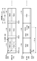
- FIG. 9 shows a first example of UL data transmission in the second access.
- DL radio frame 900 includes consecutive DL subframes 910, 920, and 930.
- UL radio frame 940 includes successive UL subframes 950, 960 and 970.
- the duration of each UL sub-frame and DL sub-frame is 1 ms.
- the PDCCH is mapped to the PDCCH resource 911 of the first two symbols, and the PDSCH is mapped to the remaining PDSCH region 912.
- the resource mapping of the other DL subframes 920 and 930 is the same as that of the DL subframe 910.
- PUCCH is mapped to PUCCH areas 951 and 952 at both ends of the UL system band, and PUSCH is mapped to the remaining PUSCH area 953.
- the resource mapping of the other UL subframes 960 and 970 is the same as that of the UL subframe 950.
- the non-legacy UE 2 transmits SR 982 using the first few symbols (e.g., 3 symbols) of the PUCCH region 951 of the UL subframe 950. Instead, the SR 982 may be transmitted using the resources of both PUSCH regions 951 and 952 as in the case of transmission of SR in the existing PUCCH region.
- BS 3 determines UL resource allocation to non-legacy UE 2, and transmits UL scheduling grant (UL grant) 984 in PDCCH region 921 of DL subframe 920.
- UL grant 984 indicates the allocation of time-frequency resources (here resource blocks) in the next UL subframe 970.
- non-legacy UE 2 transmits UL data 986 using the allocated resource block in PUSCH region 973 of UL subframe 970.
- the required time (access delay) from the transmission of SR to the completion of UL data transmission is about 2.5 ms.
- the UE receives a UL grant on the PDCCH of subframe #n, it is defined that user data is transmitted on the PUSCH of subframe # n + k.
- k 4
- a value from 4 to 7 is defined according to TDD UL / DL configuration.
- the value of the second TTI may be a fixed value, or may be set by RRC signaling or the like. In the case of TDD, it may be a value uniquely determined by a combination of the second TTI value and the timing of receiving UL grant (subframe #), or may be set by RRC signaling or the like.
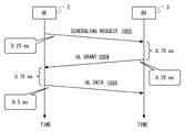
- FIG. 10 shows an example of the transmission timing in the example of FIG.
- the scheduling request 1002 corresponds to the SR 982 in FIG. 9, the UL grant 1004 corresponds to the UL grant 984 in FIG. 9, and the UL data 1006 corresponds to the UL data 986 in FIG.
- the transmission of SR1002 (982) requires about 0.25 ms.
- BS3 transmits UL grant 1004 (984) at the head of the next DL subframe (920) about 0.75 ms after receiving SR1002 (982).
- Transmission of UL grant 1004 (984) requires approximately 0.25 ms.
- UE2 transmits UL data 1006 (986) in a UL subframe (970) starting about 0.75 ms after receiving UL grant 1004 (984).
- the required time (access delay) from the transmission of the SR 1002 (982) to the completion of the transmission of the UL data 1006 (986) is about 2.5 ms.
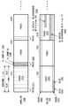
- FIG. 11 shows a second example of UL data transmission in the second access.
- the same radio frame structure as LTE and LTE-Advanced is used. That is, DL radio frame 1100 includes consecutive DL subframes 1110, 1120, and 1130.
- UL radio frame 1140 includes successive UL subframes 1150, 1160, and 1170. The duration of each UL sub-frame and DL sub-frame is 1 ms.
- DL subframe 1110 PDCCH is mapped to PDCCH resource 1111 of the first two symbols. Furthermore, the DL subframe 1110 includes an EPDCCH region 1114. PDSCH is mapped to the remaining PDSCH region 1112. The resource mapping of the other DL subframes 1120 and 1130 is the same as that of the DL subframe 1110.
- UL subframe 1150 PUCCH is mapped to PUCCH areas 1151 and 1152 at both ends of the UL system band, and PUSCH is mapped to the remaining PUSCH area 1153.
- the resource mapping of the other UL subframes 1160 and 1170 is the same as that of the UL subframe 1150.
- the non-legacy UE 2 transmits SR 1182 using the first few symbols (e.g., 3 symbols) in the PUCCH region 1151 of the UL subframe 1150. Instead, the SR 1182 may be transmitted using both the resources of the PUSCH regions 1151 and 1152 at both ends, similarly to the SR transmission in the existing PUCCH region.
- BS 3 determines UL resource allocation to non-legacy UE 2 and transmits UL grant 1184 in EPDCCH region 1114 of DL subframe 1110.
- UL grant 1184 indicates time-frequency resource allocation in the next UL subframe 1160.
- non-legacy UE 2 transmits UL data 1186 using the assigned time-frequency resources in PDSCH region 1163 of UL subframe 1160. Therefore, in the example of FIG. 11, the required time (access delay) from the transmission of SR to the completion of UL data transmission is about 1.75 ms.
- FIG. 12 shows an example of transmission timing in the example of FIG.
- the scheduling request 1202 corresponds to the SR 1182 in FIG. 11, the UL grant 1204 corresponds to the UL grant 1184 in FIG. 11, and the UL data 1206 corresponds to the UL data 1186 in FIG.
- the transmission of SR 1202 (1182) requires about 0.25 ⁇ ms.
- BS3 transmits UL grant 1204 (1184) in the second slot of the DL subframe (1120) about 0.5 ⁇ ms after receiving SR1202 (1182). Transmission of UL grant 1204 (1184) requires approximately 0.25 ms.
- the UE2 transmits UL data 1206 (1186) in the second slot of the UL subframe (1170) starting about 0.5 ⁇ ms after receiving UL grant 1204 (1184).
- the required time (access delay) from the transmission of SR 1202 (1182) to the completion of the transmission of UL data 1206 (1186) is approximately 7.75 ms.
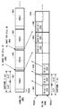
- FIG. 13 shows a third example of UL data transmission in the second access.
- the same radio frame structure as that of LTE and LTE-Advanced is used. That is, DL radio frame 1300 includes consecutive DL subframes 1310, 1320, and 1330.
- UL radio frame 1340 includes successive UL subframes 1350, 1360, and 1370. The duration of each UL sub-frame and DL sub-frame is 1 ms.
- the PDCCH is mapped to the PDCCH resource 1311 of the first two symbols, and the PDSCH is mapped to the remaining PDSCH region 1312.
- the resource mapping of the other DL subframes 1320 and 1330 is the same as that of the DL subframe 1210.
- PUCCH is mapped to PUCCH areas 1351 and 1352 at both ends of the UL system band, and PUSCH is mapped to the remaining PUSCH area 1353.
- the resource mapping of the other UL subframes 1360 and 1370 is the same as that of the UL subframe 1250.
- the second access of two non-legacy UEs 2 (referred to as UE 2A and UE 2B) is performed in parallel.
- the non-legacy UE 2A transmits SR 1382 using the first few symbols (e.g., 3 symbols) of the PUCCH area 1351 of the UL subframe 1350.
- the non-legacy UE 2B transmits SR 1392 using the resource in the PUCCH area 1351 immediately after SR 1382.
- SR 1382 and SR 1392 may be multiplexed onto a common time-frequency resource using Code Division Multiplexing (CDM).
- CDM Code Division Multiplexing
- SR 1382 may be transmitted using both resources of PUCCH regions 1351 and 1352 at both ends, similar to transmission of SR in existing PUCCH region.
- BS3 responds to the reception of SR 1382 from UE 2A, determines UL resource allocation to non-legacy UE 2A, and transmits UL grant 1384 in PDCCH region 1321 of DL subframe 1320. Similarly, BS 3 determines UL resource allocation to non-legacy UE 2 B in response to receiving SR 1392 from UE 2 B, and transmits UL grant 1394 in PDCCH region 1321. In the example of FIG. 13, transmission of UL grant 1384 is performed using the first symbol in PDCCH region 1321, and transmission of UL grant 1394 is performed using the second symbol in PDCCH region 1321.
- non-legacy UE 2A transmits UL data 1386 using the allocated resource block in PDSCH region 1373 of UL subframe 1370. Transmission of UL data 1386 is performed according to a second TTI (0.5 ms) equal to one half of the subframe duration (1 ms).
- non-legacy UE 2B transmits UL data 1396 using the allocated resource block in PUSCH region 1373 of UL subframe 1370.
- transmission of UL data by the UE 2B in the UL subframe 1370 is performed according to a first TTI (1 ms) equal to the duration of the subframe (1 ms).
- UL data transmission by the UE 2B in the UL subframe 1370 may also be performed in accordance with the second TTI (0.5 ms). That is, the transmission in the second TTI by the UE 2B may be continuously performed twice in the UL subframe 1370.
- the UL grant may include scheduling information based on the second TTI, and may include information (e.g., flag) indicating that the scheduling information is valid for 2 TTI (1.0 ms).
- SR e.g., PUCCH
- UL data transmission e.g., PUSCH
- BS3 transmits a UE grant in response to an SR from non-legacy UE2, and non-legacy UE2 transmits UL data using UL radio resources specified by the UL grant.
- the buffer status report (Buffer Status Report (BSR) is added to the UL radio resource in addition to the data.
- BSR Buffer Status Report
- the BS 3 transmits a UL grant indicating further UL radio resource allocation to the non-legacy UE 2.
- non-legacy UE2 and BS3 may operate as follows.
- the DL radio frame 1400 includes consecutive subframes 1401, 1402, 1403, and 1404.
- UL radio frame 1440 includes consecutive UL subframes 1441, 1442, 1443, and 1444.
- BS3 allocates separate time-frequency resources for two SR transmissions in one subframe (1 ms) to one non-legacy UE2.
- the duration of each of the two individual radio resources is half the duration of the subframe (0.5 ms) and is equal to the duration of one slot.
- the non-legacy UE 2 When the UL data to be transmitted is in the buffer, the non-legacy UE 2 first transmits SR # 1-1 (1482) using the first individual radio resource (the first slot of the UL subframe 1441).
- the non-legacy UE 2 determines that there is (possibly) data that cannot be transmitted in one data transmission (eg, 0.5 ms)
- the second individual radio resource (the first of the UL subframe 1441) SR # 1-2 (1483) is transmitted in 2 slots).
- the minimum data size eg, transport block size
- the non-legacy UE 2 may determine whether or not transmission of the second SR is necessary based on the setting of the minimum data size.
- BS3 When BS3 receives SR # 1-1 (1482), it transmits UL grant # 1 (1484) in DL subframe 1402. On the other hand, BS3 does not transmit an explicit UL grant to SR # 1-2 (1483). However, when BS3 receives SR # 1-2 (1483) following SR # 1-1 (1482), the same layer 1 format (eg, Modulation) as specified by UL grant # 1 (1484) is received. and Coding Scheme (MCS), resource block (subcarrier)) is implicitly permitted.
- MCS Coding Scheme
- the third individual radio resource (the first of the UL subframe 1442) Another SR # 2-1 (1492) is transmitted in one slot).
- non-legacy UE2 does not transmit SR # 2-2 in the slot immediately after SR # 2-1 (1492) (second slot of UL subframe 1442). This is because, for example, there is no more data to be transmitted, that is, transmission is expected to be completed with UL grants for SR # 1-1, SR # 1-2, and SR # 2-1.
- Non-legacy UE2 transmits UL data # 1-1 (1486) in the first slot of UL subframe 1443 using the UL radio resource specified by UL grant # 1 (1484).
- the non-legacy UE 2 may transmit a BSR in the data transmission.
- UL data # 1-1 (1487) is transmitted in the same layer 1 format (eg, MCS, resource block (subcarrier)) as UL data # 1-1 (1486).
- layer 1 format eg, MCS, resource block (subcarrier)
- BS3 When BS3 receives SR # 2-1 (1492), it transmits UL grant # 2 (1494) in DL subframe 1403. Since BS3 has not received the fourth SR # 2-2, implicit transmission permission is not performed.
- Non-legacy UE2 transmits UL data # 2-1 (1496) in the first slot of UL subframe 1444 using the UL radio resource specified by UL grant # 2 (1494). Since the non-legacy UE 2 does not transmit the SR # 2-2, the non-legacy UE2 does not transmit the radio resource 1450 in the slot immediately after transmitting the UL data # 2-1 (1496).
- BS3 may allocate the radio resource 1450 after UL data # 2-1 (1496) to another UE when the second SR # 2-2 is not received from the non-legacy UE2.
- the non-legacy UE 2 determines whether or not a condition for permitting the second access is satisfied, and performs data transmission or reception by the second access when the condition is satisfied. If the non-legacy UE2 does not satisfy the condition, the non-legacy UE2 may perform data transmission or reception by the first access, or move to another cell (eg, cell reselection) and try the second access. Also good.
- the condition for allowing the second access may be preset in the non-legacy UE2. Instead, at least part of the condition may be notified from the BS 3 to the non-legacy UE 2.
- the non-legacy UE 2 when triggered by UL data transmission, determines whether or not the second access condition is permitted, and if the condition is satisfied, the non-legacy UE 2 You may carry out according to 2nd TTI.
- the non-legacy UE 2 determines whether the second access condition is allowed when triggered by receiving a DL message that requires a response, and if the condition is met The transmission for the response may be performed according to the second TTI.
- the DL message that requires a response is, for example, paging or DL grant.
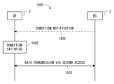
- FIG. 15 is a sequence diagram illustrating an example of the second access start procedure (processing 1500).
- BS3 notifies UE2 of at least a part of the conditions for which the second access is permitted (condition (notification).
- condition notification
- the non-legacy UE 2 determines whether or not a condition for allowing the second access is satisfied. When the condition is satisfied, the non-legacy UE 2 performs data transmission or reception by the second access (1503).
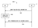
- FIG. 16 is a sequence diagram showing another example (process 1600) of the second access start procedure.
- BS3 transmits information related to the condition for which the second access is permitted (condition related information) to the non-legacy UE 2.
- BS3 transmits information about conditions under which second access is permitted in the cell managed by BS3 in RRC message (eg, RRC Connection Reconfiguration) or system information (eg, System Information Block (SIB)). May be.
- BS3 receives information about the conditions from the upper network device (eg, Mobility Management Entity (MME), Serving Gateway (S-GW), Packet Data Network Gateway (P-GW), or Application server). It may be transferred to UE2 (transparently).
- MME Mobility Management Entity
- S-GW Serving Gateway
- P-GW Packet Data Network Gateway
- Application server Application server
- the non-legacy UE 2 determines whether or not a condition defined based on the information notified from the BS 3 is satisfied. When the condition is satisfied, the UE 2 performs data transmission or reception by the second access (1603).
- condition under which the second access is permitted in the determination by the non-legacy UE 2 may be, for example, any one or any combination of the following conditions 1 to 8.
- Condition 1 Data transmission that requires second access depends on the higher layer (eg, Non-Access Stratum (NAS) or The UE 2 may be notified from the application layer.
- the non-legacy UE2 does not always require a low delay. For example, when the non-legacy UE 2 is a vehicle-mounted terminal, it can be assumed that the data transmission or reception in an emergency at the time of automatic driving (autonomous driving) has a severe delay requirement compared to normal data transmission or reception. That is, the second access may be permitted only when the non-legacy UE 2 executes a specific application or service.
- Second access to non-legacy UE 2 is permitted (or approved) in advance. Whether or not the second access is permitted in advance may be notified to UE2 from an upper layer (eg, NAS or application layer).
- the Access Stratum (AS) layer of the non-legacy UE 2 performs the second access when notified by the upper layer (or notified in advance) that the second access is permitted (or approved). You may make it perform. For example, when an upper layer is notified of permission (or approval) of second access from a wireless network (eg, MME, Home Subscriber Server (HSS), or application server), the second access is permitted in advance. You may recognize that.
- a wireless network eg, MME, Home Subscriber Server (HSS), or application server
- the upper layer may have the intended application or service in advance as a contract operator or a wireless network (eg, registered Public Land Mobile It may be determined whether or not the second access in the network (PLMN) is permitted (or approved).
- a wireless network eg, registered Public Land Mobile It may be determined whether or not the second access in the network (PLMN) is permitted (or approved).
- the second access is permitted (or possible) in the serving cell to which the non-legacy UE 2 is connected.
- the non-legacy UE 2 receives broadcast information (SIB) or individual control information (RRC signaling such as RRC Connection Reconfiguration) and determines whether or not the second access is permitted or not.
- SIB broadcast information
- RRC signaling such as RRC Connection Reconfiguration
- the serving cell may be a Carrier Aggregation SCell, or a Dual Connectivity PSCell or SCell.
- the type of the second access is permitted in the serving cell to which the non-legacy UE 2 is connected.
- the non-legacy UE 2 receives broadcast information or dedicated control information, and an intended application or service is received in the serving cell. It is determined whether the type is permitted (access type), purpose (access cause), or use (use case).
- the serving cell may be a Carrier Aggregation SCell, or a Dual Connectivity PSCell or SCell.
- the non-legacy UE 2 has configuration information (configuration) related to the second access.
- the non-legacy UE 2 (a) sets the configuration information (D-SR configuration ( D-SR2)), (b) auxiliary information of radio resources in data transmission by the second access (eg, truncated MCS set, candidate PRB set, candidate TTI length set, or maximum transport block (TB) size), or ( c)
- D-SR configuration D-SR2
- auxiliary information of radio resources in data transmission by the second access eg, truncated MCS set, candidate PRB set, candidate TTI length set, or maximum transport block (TB) size
- radio resource setting information eg, MCS, PRB, and TTI length
- the second access is preferable to the first access.
- the non-legacy UE 2 performs the first access when radio resources are already allocated, and the second access otherwise. Access may be made.
- the non-legacy UE 2 may perform the first access when the conventional D-SR is already transmitted, and may perform the second access otherwise.
- Condition 7 Data transmission is possible (completed) in the second access.
- the non-legacy UE 2 performs the second access if the radio quality is equal to or higher than the determination quality for performing the second access.
- the first access may be performed.
- the non-legacy UE 2 may perform the second access if the TB size is equal to or smaller than the determination size that can be transmitted by the second access, and may perform the first access otherwise.
- Condition 8 A signal (DL signal) to be responded to in the second access has been received.
- the non-legacy UE 2 has received a paging or DL grant corresponding to the second access (requesting the second access).
- the second access may be performed.
- the non-legacy UE 2 may apply the second access only to Radio Link Control (RLC) Unacknowledged Mode (UM). Further, the non-legacy UE 2 may invalidate (not apply) segmentation and re-segmentation in the second access.
- RLC Radio Link Control
- UM Unacknowledged Mode
- the non-legacy UE 2 determines whether or not the second access is permitted, and the second access is performed only when the second access is permitted. I do. Thereby, for example, the non-legacy UE 2 can be controlled so that the second access is performed only in a situation where the second access is suitable. Therefore, the non-legacy UE 2 that performs the second access can be efficiently accommodated in the wireless communication system together with the legacy UE 1 that does not perform the second access.
- BS3 determines whether or not the condition for permitting the second access with respect to the non-legacy UE2 is satisfied, and determines that the UE2 is permitted (or allowed to perform) the second access when the condition is satisfied.
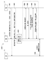
- FIG. 17 is a sequence diagram showing an example of the second access start procedure (process 1700).
- the non-legacy UE2 transmits access related information (Access Related Information) to the BS3.
- the non-legacy UE 2 may transmit the access related information in a radio connection establishment completion message (RRC Connection Setup Complete), a radio connection setup completion message (RRC Connection Reconfiguration Complete), or another RRC message.
- the BS 3 determines whether or not a condition for permitting the second access for the non-legacy UE 2 is satisfied. If the condition is satisfied, the BS 3 performs the second access with the UE 2 (1703). If UE2 does not satisfy the condition, BS3 may cause UE2 to perform data transmission or reception by the first access or move UE2 to another cell (eg, handover, redirection, for example). to other frequency cell). UE2 may try the second access in the other cell.
- a condition for permitting the second access for the non-legacy UE 2 is satisfied. If the condition is satisfied, the BS 3 performs the second access with the UE 2 (1703). If UE2 does not satisfy the condition, BS3 may cause UE2 to perform data transmission or reception by the first access or move UE2 to another cell (eg, handover, redirection, for example). to other frequency cell). UE2 may try the second access in the other cell.
- FIG. 18 is a sequence diagram showing an example of the second access start procedure (process 1800).
- the non-legacy UE 2 transmits access related information (Access Related Information) to the MME 4.
- access related information Access Related Information
- MME4 access-related information
- UE2 may transmit this to BS3 as NAS layer information, and BS3 may transfer the information to MME4 by a terminal message (Initial UE Message).
- the MME 4 transmits access control information (Access control information) including at least part of the access related information or authorization information (Access control information) for the second access to the BS 3.
- the MME 4 may transmit access control information using a terminal context setup request (Initial Context Setup Request).
- the BS 3 determines whether or not the condition for permitting the second access for the non-legacy UE 2 is satisfied. If the condition is satisfied, the BS 3 performs the second access with the UE 2 (1804). If UE2 does not satisfy the condition, BS3 may cause UE2 to perform data transmission or reception by the first access or move UE2 to another cell (eg, handover, redirection, for example). to other frequency cell). UE2 may try the second access in the other cell.
- another cell eg, handover, redirection, for example.
- the access related information (Access Related Information) related to the second access may be any one of the following (1) to (3) or any combination.
- Radio terminal capability information (UE radio access capability, eg, UE-EUTRA-Capability) Information indicating that the UE has a function (capability) of data transmission or reception by the second access may be newly added to the existing wireless terminal capability information. For example, set a value such as “low latency access”, “lower latency access”, “short TTI”, “TTI shortening”, “critical access”, or “mission critical access” to “supported” for the UE radio access capability. May be.
- Access purpose (Access cause, eg, EstablishmentCause) Information indicating that data transmission or reception by the second access is performed may be newly added for the existing access purpose. For example, a value such as “low latency access”, “lower latency access”, “short TTI access”, “TTI shortening access”, “critical access”, or “mission critical access” may be added to the Access cause.
- the information may be information indicating what application or service is intended (desired).
- the non-legacy UE 2 may select and report an intended (desired) type from preset application / service types (eg, type, category).
- the access control information (Access control information) sent from the MME 4 to the BS 3 may be any of the following (1) to (3) or any combination.
- the MME 4 may determine whether or not to permit the second access by the UE 2 and transmit the result to the BS 3.
- MME4 receives the second by UE2 from another network node (eg, HSS or application server). An inquiry may be made as to whether or not access is approved, and the result may be transmitted to the BS 3.
- another network node eg, HSS or application server.
- the condition under which the second access is permitted in the determination by the BS 3 may be, for example, any one of the following conditions 1 to 6 or any combination thereof.
- Condition 1 Data transmission that requires the second access BS3 determines whether the data transmission requires the second access based on the access-related information received from the non-legacy UE2. May be. Alternatively, the BS 3 may determine whether or not the data transmission requires the second access based on the access control information received from the upper network device (eg, MME or application server). .
- the upper network device eg, MME or application server.
- Second access to non-legacy UE 2 is permitted (or approved) in advance. Whether the second access is permitted in advance may be notified to the BS 3 from a higher-level network device (eg, MME or application server).
- a higher-level network device eg, MME or application server.
- the host network device is notified of permission (or approval) of the second access from another network node (eg, HSS or application server)
- the higher-level network device can either have the intended application or service in advance as a contract operator or a wireless network (eg, registered PLMN) It may be determined whether or not the second access is permitted (or approved).
- Condition 3 The second access is permitted (or possible) in the serving cell to which the non-legacy UE 2 is connected.
- Condition 4 The type of second access permitted by the serving cell to which the non-legacy UE 2 is connected
- Condition 5 Data transmission is possible (completed) by the second access BS3 performs the second access if the wireless quality is equal to or higher than the determination quality for performing the second access, for example, otherwise the first access 1 access may be performed. Instead, the BS 3 may perform the second access if the TB size is equal to or smaller than the determination size that can be transmitted by the second access, and may perform the first access otherwise.
- Condition 6 A signal to be responded to by the second access is received.
- BS3 desires non-legacy UE2 to transmit data in response to paging corresponding to the second access (requesting the second access).
- the second access may be permitted to the UE2.
- BS3 may apply the second access only to RLCRLUM. Further, BS3 may invalidate (not apply) segmentation and re-segmentation in the second access.
- the BS 3 determines whether or not to permit the second access. Thereby, for example, the BS 3 can control the non-legacy UE 2 to perform the second access only in a situation where the second access is suitable. Therefore, the non-legacy UE 2 that performs the second access can be efficiently accommodated in the wireless communication system together with the legacy UE 1 that does not perform the second access.
- D2D communication Device-to-Device communication
- D2D discovery Device discovery
- Proximity based Service ProSe
- the direct interface between UEs for Direct communication and Direct discovery is called sidelink (sidelink (SL)) or PC5 interface.
- the side link uses the uplink frequency as described above. Therefore, the UE is used on the side link corresponding to a part of the existing uplink radio resources of LTE to perform ProSe, that is, to perform side link communication (Direct discovery and / or Direct communication). It is necessary to acquire information on the wireless resources to be acquired.
- the UE acquires SL control information in System information (e.g., SIB18 for Direct communication, SIB19 for Direct discovery).
- System information e.g., SIB18 for Direct communication, SIB19 for Direct discovery.
- a common SL radio resource (Resource pool) that is commonly allocated among a plurality of UEs is notified.
- the UE for which ProSe is permitted arbitrarily selects a radio resource from the common SL radio resources, and performs side link communication (that is, at least one of Direct discovery and Direct communication).
- the UE acquires SL control information in dedicated signaling (e.g., RRC, MAC).
- dedicated signaling a common SL radio resource or an individual SL radio resource (Dedicated resource) allocated individually (for example, for each group) is sent from the eNB to the UE.
- the UE receives the common SL radio resource by dedicated signaling, the UE overwrites the information on the common SL radio resource notified by System information.
- the dedicated SL radio resource is received by dedicated signaling, the UE performs side link communication using the dedicated SL radio resource.
- the information indicating the individual SL radio resource for Direct communication is also referred to as Sidelink grant (SL grant).
- the method using common SL radio resources is called (UE) autonomous resource selection method, and the method using individual SL radio resources is called Scheduled resource allocation (by eNB) method.
- the method and procedure for acquiring SL control information for Direct discovery may be different from or common to the method and procedure for acquiring SL control information for Direct communication.
- FIG. 19 is a diagram showing an example of a communication procedure (process 1900) according to the present embodiment.
- Non-legacy UE2 receives ProSe configuration from BS3 in SIB (1901) or dedicated signaling (1902).
- the non-legacy UE 2 When the non-legacy UE 2 is triggered by Direct communication and satisfies a predetermined condition (block 1903), the non-legacy UE 2 transmits an SR to the BS 3 (1904).
- the non-legacy UE2 receives the UL grant from BS3.
- the non-legacy UE2 sends a ProSe BSR using the assigned UL resource (PUSCH) to request resource assignment for Direct communication.
- the non-legacy UE2 receives a scheduling grant (SL ⁇ ⁇ ⁇ grant) from BS3 indicating resource allocation for side link communication (Direct communication).
- UE2 performs direct communication with UE5 using the radio resource allocated from BS3.
- At least part of the transmission / reception of the blocks 1904 to 1907 may be performed according to the second access described in the above embodiment.
- the UL data transmission at block 1906 may be performed according to a second access according to a second TTI.
- the SR of block 1904 may be transmitted in a format or timing defined for the second access (ie, low latency access).
- transmission / reception of blocks 1904 to 1907 may be performed according to the first access (existing access).
- the non-legacy UE 2 may perform direct communication using the radio resource selected from the resource pool without performing blocks 1904 to 1907. .
- FIG. 20 is a block diagram illustrating a configuration example of the non-legacy UE 2.
- the Radio-Frequency (RF) transceiver 2001 performs analog RF signal processing to communicate with the BS 3.
- the RF transceiver 2001 may also be used for side link communication (Direct discovery and Direct communication) with other UEs.
- the RF transceiver 2001 may include a first transceiver used for communication with the BS 3 and a second transceiver used for side link communication with other UEs.
- Analog RF signal processing performed by the RF transceiver 2001 includes frequency up-conversion, frequency down-conversion, and amplification.
- RF transceiver 2001 is coupled to antenna 2002 and baseband processor 2003. That is, the RF transceiver 2001 receives modulation symbol data (or OFDM symbol data) from the baseband processor 2003, generates a transmission RF signal, and supplies the transmission RF signal to the antenna 2002. Further, the RF transceiver 2001 generates a baseband received signal based on the received RF signal received by the antenna 2002 and supplies this to the baseband processor 2003.
- modulation symbol data or OFDM symbol data
- the baseband processor 2003 performs digital baseband signal processing (data plane processing) and control plane processing for wireless communication.
- Digital baseband signal processing consists of (a) data compression / decompression, (b) data segmentation / concatenation, (c) ⁇ transmission format (transmission frame) generation / decomposition, and (d) transmission path encoding / decoding. , (E) modulation (symbol mapping) / demodulation, and (f) generation of OFDM symbol data (baseband OFDM signal) by Inverse Fast Fourier Transform (IFFT).
- control plane processing includes layer 1 (eg, transmission power control), layer 2 (eg, radio resource management, hybrid automatic repeat request (HARQ) processing), and layer 3 (eg, attach, mobility, and call management). Communication management).
- the digital baseband signal processing by the baseband processor 2003 may include signal processing of a Packet Data Convergence Protocol (PDCP) layer, an RLC layer, a MAC layer, and a PHY layer.
- PDCP Packet Data Convergence Protocol
- the control plane processing by the baseband processor 2003 may include processing of NAS protocol and RRC protocol.
- the baseband processor 2003 includes a modem processor (eg, Digital Signal Processor (DSP)) that performs digital baseband signal processing and a protocol stack processor (eg, Central Processing Unit (CPU) that performs control plane processing, or Micro Processing Unit. (MPU)).
- DSP Digital Signal Processor
- protocol stack processor eg, Central Processing Unit (CPU) that performs control plane processing, or Micro Processing Unit. (MPU)
- CPU Central Processing Unit
- MPU Micro Processing Unit.
- a protocol stack processor that performs control plane processing may be shared with an application processor 2004 described later.
- the application processor 1904 is also called a CPU, MPU, microprocessor, or processor core.
- the application processor 2004 may include a plurality of processors (a plurality of processor cores).
- the application processor 2004 is a system software program (Operating System (OS)) read from the memory 2006 or a memory (not shown) and various application programs (for example, a call application, a web browser, a mailer, a camera operation application, music playback)
- OS Operating System
- the baseband processor 2003 and the application processor 2004 may be integrated on a single chip, as indicated by the dashed line (2005) in FIG.
- the baseband processor 2003 and the application processor 2004 may be implemented as one System on Chip (SoC) device 2005.
- SoC System on Chip
- An SoC device is sometimes called a system Large Scale Integration (LSI) or chipset.
- the memory 2006 is a volatile memory, a nonvolatile memory, or a combination thereof.
- the memory 2006 may include a plurality of physically independent memory devices.
- the volatile memory is, for example, Static Random Access Memory (SRAM), Dynamic RAM (DRAM), or a combination thereof.
- the non-volatile memory is a mask Read Only Memory (MROM), Electrically Erasable Programmable ROM (EEPROM), flash memory, hard disk drive, or any combination thereof.
- the memory 2006 may include an external memory device accessible from the baseband processor 2003, the application processor 2004, and the SoC 2005.
- Memory 2006 may include an embedded memory device integrated within baseband processor 2003, application processor 2004, or SoC 2005.
- the memory 2006 may include a memory in a Universal Integrated Circuit Card (UICC).
- UICC Universal Integrated Circuit Card
- the memory 2006 may store a software module (computer program) including an instruction group and data for performing processing by the non-legacy UE 2 described in the plurality of embodiments described above.
- the baseband processor 2003 or the application processor 2004 may be configured to perform the processing of the non-legacy UE 2 described in the above-described embodiment by reading the software module from the memory 2006 and executing the software module. Good.
- FIG. 21 is a block diagram illustrating a configuration example of the BS 3 according to the above-described embodiment.
- BS 3 includes an RF transceiver 2101, a network interface 2103, a processor 2104, and a memory 2105.
- RF transceiver 2101 performs analog RF signal processing to communicate with legacy UE1 and non-legacy UE2.
- the RF transceiver 2101 may include a plurality of transceivers.
- RF transceiver 2101 is coupled to antenna 2102 and processor 2104.
- the RF transceiver 2101 receives modulation symbol data (or OFDM symbol data) from the processor 2104, generates a transmission RF signal, and supplies the transmission RF signal to the antenna 2102. Further, the RF transceiver 2101 generates a baseband received signal based on the received RF signal received by the antenna 2102, and supplies this to the processor 2104.
- the network interface 2103 is used to communicate with network nodes (e.g., MME and S / P-GW).
- the network interface 2103 may include, for example, a network interface card (NIC) compliant with IEEE 802.3 series.
- NIC network interface card
- the processor 2104 performs digital baseband signal processing (data plane processing) and control plane processing for wireless communication.
- the digital baseband signal processing by the processor 2104 may include signal processing of a PDCP layer, an RLC layer, a MAC layer, and a PHY layer.
- the control plane processing by the processor 2104 may include processing of the S1 protocol and the RRC protocol.
- the processor 2104 may include a plurality of processors.
- the processor 2104 may include a modem processor (e.g., DSP) that performs digital baseband signal processing and a protocol stack processor (e.g., CPU or MPU) that performs control plane processing.
- DSP digital baseband signal processing
- protocol stack processor e.g., CPU or MPU
- the memory 2105 is configured by a combination of a volatile memory and a nonvolatile memory.
- the volatile memory is, for example, SRAM or DRAM or a combination thereof.
- the non-volatile memory is, for example, an MROM, PROM, flash memory, hard disk drive, or a combination thereof.
- Memory 2105 may include storage located remotely from processor 2104. In this case, the processor 2104 may access the memory 2105 via the network interface 2103 or an I / O interface not shown.
- the memory 2105 may store a software module (computer program) including an instruction group and data for performing processing by the BS 3 described in the plurality of embodiments.
- the processor 2104 may be configured to read the software module from the memory 2105 and execute the software module to perform the process of BS3 described in the above-described embodiment.
- each of the processors included in the non-legacy UE 2 and BS 3 includes a group of instructions for causing a computer to execute the algorithm described with reference to the drawings.
- One or more programs are executed.
- the program can be stored and supplied to a computer using various types of non-transitory computer readable media.
- Non-transitory computer readable media include various types of tangible storage media (tangible storage medium).
- non-transitory computer-readable media are magnetic recording media (eg flexible disks, magnetic tapes, hard disk drives), magneto-optical recording media (eg magneto-optical discs), Compact Disc Read Only Memory (CD-ROM), CD-ROM R, CD-R / W, semiconductor memory (for example, mask ROM, Programmable ROM (PROM), Erasable PROM (EPROM), flash ROM, Random Access Memory (RAM)).
- the program may also be supplied to the computer by various types of temporary computer-readable media. Examples of transitory computer readable media include electrical signals, optical signals, and electromagnetic waves.
- the temporary computer-readable medium can supply the program to the computer via a wired communication path such as an electric wire and an optical fiber, or a wireless communication path.
Landscapes
- Engineering & Computer Science (AREA)
- Signal Processing (AREA)
- Computer Networks & Wireless Communication (AREA)
- Mobile Radio Communication Systems (AREA)
Abstract
L'invention concerne une station sans fil (3) qui attribue à au moins un terminal sans fil (1, 2) une pluralité de premières ressources temps-fréquence (430) et une pluralité de deuxièmes ressources temps-fréquence (530). La pluralité de premières ressources temps-fréquence (430) est utilisée pour transmettre ou recevoir un premier bloc de transport (460) dans un premier intervalle de temps de transmission (TTI). Le premier TTI est identique à la durée de la sous-trame (410, 510). La pluralité de deuxièmes ressources temps-fréquence (530) est utilisée pour transmettre ou recevoir un deuxième bloc de transport (560) dans un deuxième TTI. Le deuxième TTI est plus court que la durée de la sous-trame (410, 510).
Priority Applications (6)
| Application Number | Priority Date | Filing Date | Title |
|---|---|---|---|
| EP15884477.9A EP3267747B1 (fr) | 2015-03-06 | 2015-12-24 | Latence réduite de la transmission d'une demande de programmation à la transmission de données ul |
| EP20205877.2A EP3793294A1 (fr) | 2015-03-06 | 2015-12-24 | Configuration pour intervalle de temps de transmission court |
| US15/552,642 US10342016B2 (en) | 2015-03-06 | 2015-12-24 | Radio station, radio terminal apparatus, and method for these |
| JP2017504307A JP6658729B2 (ja) | 2015-03-06 | 2015-12-24 | 無線局、無線端末装置、及びこれらの方法 |
| US16/428,659 US20190289605A1 (en) | 2015-03-06 | 2019-05-31 | Radio station, radio terminal apparatus, and method for these |
| US17/731,477 US11974261B2 (en) | 2015-03-06 | 2022-04-28 | Method, user equipment and access network node allocating resources in accordance with transmission time intervals |
Applications Claiming Priority (2)
| Application Number | Priority Date | Filing Date | Title |
|---|---|---|---|
| JP2015045124 | 2015-03-06 | ||
| JP2015-045124 | 2015-03-06 |
Related Child Applications (2)
| Application Number | Title | Priority Date | Filing Date |
|---|---|---|---|
| US15/552,642 A-371-Of-International US10342016B2 (en) | 2015-03-06 | 2015-12-24 | Radio station, radio terminal apparatus, and method for these |
| US16/428,659 Continuation US20190289605A1 (en) | 2015-03-06 | 2019-05-31 | Radio station, radio terminal apparatus, and method for these |
Publications (1)
| Publication Number | Publication Date |
|---|---|
| WO2016142979A1 true WO2016142979A1 (fr) | 2016-09-15 |
Family
ID=56880021
Family Applications (1)
| Application Number | Title | Priority Date | Filing Date |
|---|---|---|---|
| PCT/JP2015/006441 WO2016142979A1 (fr) | 2015-03-06 | 2015-12-24 | Station sans fil, dispositif terminal sans fil et procédé associés |
Country Status (4)
| Country | Link |
|---|---|
| US (3) | US10342016B2 (fr) |
| EP (2) | EP3267747B1 (fr) |
| JP (2) | JP6658729B2 (fr) |
| WO (1) | WO2016142979A1 (fr) |
Cited By (4)
| Publication number | Priority date | Publication date | Assignee | Title |
|---|---|---|---|---|
| WO2018203396A1 (fr) * | 2017-05-02 | 2018-11-08 | 株式会社Nttドコモ | Terminal utilisateur et procédé de communication sans fil |
| CN111247822A (zh) * | 2017-11-17 | 2020-06-05 | 松下电器(美国)知识产权公司 | 用户设备、基站及其通信 |
| US11388746B2 (en) | 2017-02-03 | 2022-07-12 | Telefonaktiebolaget Lm Ericsson (Publ) | Methods and apparatus for utilizing short transmission time intervals in a wireless communications network |
| CN115243379A (zh) * | 2017-11-07 | 2022-10-25 | Oppo广东移动通信有限公司 | 一种传输时刻确定方法及装置、计算机存储介质 |
Families Citing this family (23)
| Publication number | Priority date | Publication date | Assignee | Title |
|---|---|---|---|---|
| US10887793B2 (en) * | 2015-03-06 | 2021-01-05 | Nec Corporation | Radio station, radio terminal apparatus, and method for these |
| US9936519B2 (en) | 2015-03-15 | 2018-04-03 | Qualcomm Incorporated | Self-contained time division duplex (TDD) subframe structure for wireless communications |
| US10075970B2 (en) * | 2015-03-15 | 2018-09-11 | Qualcomm Incorporated | Mission critical data support in self-contained time division duplex (TDD) subframe structure |
| US9814058B2 (en) | 2015-05-15 | 2017-11-07 | Qualcomm Incorporated | Scaled symbols for a self-contained time division duplex (TDD) subframe structure |
| US10863492B2 (en) * | 2015-07-16 | 2020-12-08 | Qualcomm Incorporated | Low latency device-to-device communication |
| US9992790B2 (en) | 2015-07-20 | 2018-06-05 | Qualcomm Incorporated | Time division duplex (TDD) subframe structure supporting single and multiple interlace modes |
| CN106413106B (zh) * | 2015-07-28 | 2019-09-17 | 电信科学技术研究院 | 一种上行数据的传输方法及装置 |
| US10506623B2 (en) | 2015-08-21 | 2019-12-10 | Lg Electronics Inc. | Method for triggering a BSR for sidelink data in a D2D communication system and device therefor |
| KR20200020011A (ko) * | 2015-08-21 | 2020-02-25 | 후아웨이 테크놀러지 컴퍼니 리미티드 | 무선 통신 방법, 네트워크 디바이스, 사용자 장비 및 시스템 |
| US10868645B2 (en) * | 2015-11-06 | 2020-12-15 | Huawei Technologies Co., Ltd. | Method and base station for transmitting downlink data |
| CN108702345B (zh) * | 2015-12-18 | 2022-04-05 | 弗劳恩霍夫应用研究促进协会 | 无线通信系统中具有缩短的端到端延时的数据信号传输 |
| US10225041B2 (en) * | 2016-01-15 | 2019-03-05 | Qualcomm Incorporated | Methods and apparatus for higher modulation support in LTE |
| CN107040347B (zh) | 2016-02-03 | 2021-05-25 | 电信科学技术研究院 | 一种上行传输方法及装置 |
| EP3399683A4 (fr) * | 2016-02-05 | 2019-05-01 | Huawei Technologies Co., Ltd. | Procédé et appareil d'envoi d'informations de retour |
| US10791571B2 (en) * | 2016-04-26 | 2020-09-29 | Lg Electronics Inc. | Downlink signal receiving method and user equipment, and downlink signal transmission method and base station |
| JP2018026703A (ja) * | 2016-08-10 | 2018-02-15 | ソニー株式会社 | 通信装置、通信方法及び記録媒体 |
| KR102114940B1 (ko) * | 2016-10-31 | 2020-05-26 | 주식회사 케이티 | 차세대 무선 액세스망을 위한 데이터 채널 자원 할당 방법 및 장치 |
| CN110114997B (zh) | 2016-10-31 | 2021-12-10 | 株式会社Kt | 针对下一代无线接入网络分配数据信道资源的方法和设备 |
| US10602498B2 (en) * | 2016-11-04 | 2020-03-24 | Asustek Computer Inc. | Method and apparatus for signaling different short TTI (transmission time interval) band in shortened TTI in a wireless communication system |
| CN111512684B (zh) * | 2018-02-05 | 2023-04-18 | Oppo广东移动通信有限公司 | 用户设备及其无线通信方法 |
| JP7116179B6 (ja) * | 2018-04-04 | 2022-10-03 | オッポ広東移動通信有限公司 | アップリンク制御情報の伝送方法及び端末 |
| CN110959300B (zh) * | 2018-07-27 | 2023-12-05 | 北京小米移动软件有限公司 | 数据传输方法、装置、设备、系统及存储介质 |
| US20220338169A1 (en) * | 2021-04-16 | 2022-10-20 | Qualcomm Incorporated | Resource allocations to source user equipment from a user equipment in a hop |
Citations (3)
| Publication number | Priority date | Publication date | Assignee | Title |
|---|---|---|---|---|
| JP2009506679A (ja) * | 2005-08-24 | 2009-02-12 | クゥアルコム・インコーポレイテッド | 無線通信システムに関する可変送信時間間隔 |
| WO2014040531A1 (fr) * | 2012-09-12 | 2014-03-20 | Huawei Technologies Co., Ltd. | Système et procédé pour structure d'intervalle de temps de transmission (tti) adaptatif |
| EP2816858A1 (fr) * | 2013-06-17 | 2014-12-24 | Alcatel Lucent | Station de base et son procédé de fonctionnement |
Family Cites Families (28)
| Publication number | Priority date | Publication date | Assignee | Title |
|---|---|---|---|---|
| JP4732808B2 (ja) | 2005-06-14 | 2011-07-27 | 株式会社エヌ・ティ・ティ・ドコモ | 無線パラメータ群を生成する装置 |
| US8644292B2 (en) | 2005-08-24 | 2014-02-04 | Qualcomm Incorporated | Varied transmission time intervals for wireless communication system |
| US8400998B2 (en) | 2006-08-23 | 2013-03-19 | Motorola Mobility Llc | Downlink control channel signaling in wireless communication systems |
| ATE502447T1 (de) * | 2006-11-02 | 2011-04-15 | Interdigital Tech Corp | Verfahren und vorrichtung zur optimierung von e- tfc-beschränkung für hsupa-kanäle |
| US8437332B2 (en) | 2009-06-22 | 2013-05-07 | Qualcomm Incorporated | Low complexity unified control channel processing |
| KR101643025B1 (ko) | 2009-08-12 | 2016-07-27 | 엘지전자 주식회사 | 중계국 및 중계국의 백홀 상향링크 신호 전송 방법 |
| EP2670065A4 (fr) * | 2011-01-26 | 2015-10-14 | Lg Electronics Inc | Procédé pour transmettre et recevoir des données de contrôle sur la liaison descendante dans un système de communication sans fil, et dispositif correspondant |
| EP2509373A1 (fr) * | 2011-04-01 | 2012-10-10 | Panasonic Corporation | Rapport de marge d'alimentation étendue efficace pour programmation semi-persistante |
| CN102158978B (zh) | 2011-04-22 | 2017-03-01 | 中兴通讯股份有限公司 | 一种下行控制信息的处理方法和系统 |
| JP5620884B2 (ja) | 2011-05-27 | 2014-11-05 | 京セラ株式会社 | 基地局及び通信方法 |
| JP5898205B2 (ja) | 2011-08-12 | 2016-04-06 | パナソニック インテレクチュアル プロパティ コーポレーション オブアメリカPanasonic Intellectual Property Corporation of America | 通信装置及び再送制御方法 |
| TWI646812B (zh) | 2012-01-24 | 2019-01-01 | 內數位專利控股公司 | 無線傳輸/接收單元、在無線傳輸/接收單元中實施的方法以及網路節點 |
| US9544884B2 (en) | 2012-04-24 | 2017-01-10 | Lg Electronics Inc. | Method for configuring resource block for search region of downlink control channel in wireless communication system, and apparatus therefor |
| KR20150013458A (ko) | 2012-05-25 | 2015-02-05 | 엘지전자 주식회사 | 신호 송수신 방법 및 이를 위한 장치 |
| US8935775B2 (en) | 2012-06-28 | 2015-01-13 | Intel Corporation | Method and apparatus for dishonest hardware policies |
| US9397735B2 (en) | 2012-08-13 | 2016-07-19 | Telefonaktiebolaget Lm Ericsson (Publ) | Retransmission methods including discontinuous transmission and related devices |
| GB2509070B (en) | 2012-12-19 | 2018-04-11 | Sony Corp | Telecommunications apparatus and methods |
| CN104919772B (zh) * | 2013-01-11 | 2018-10-12 | 交互数字专利控股公司 | 用于适应性调制的系统和方法 |
| US10305626B2 (en) * | 2013-04-05 | 2019-05-28 | Qualcomm Incorporated | Enhanced transmission time interval bundling design for machine type communications |
| US9642140B2 (en) * | 2013-06-18 | 2017-05-02 | Samsung Electronics Co., Ltd. | Methods of UL TDM for inter-enodeb carrier aggregation |
| US9184880B2 (en) * | 2013-08-01 | 2015-11-10 | Sierra Wireless, Inc. | Method and device enabling a dynamic bundle size HARQ mechanism |
| JP6210538B2 (ja) | 2013-08-27 | 2017-10-11 | 東京地下鉄株式会社 | 結合装置 |
| EP3119025A4 (fr) | 2014-03-13 | 2017-10-25 | LG Electronics Inc. | Procédé pour émettre et recevoir un signal de faible latence dans un système de communication sans fil et appareil à cet effet |
| US9942881B2 (en) | 2014-03-14 | 2018-04-10 | Telefonaktiebolaget Lm Ericsson (Publ) | Uplink multi-TTI scheduling in TDD system |
| US11019620B2 (en) | 2014-05-19 | 2021-05-25 | Qualcomm Incorporated | Apparatus and method for inter-band pairing of carriers for time division duplex transmit- and receive-switching and its application to multiplexing of different transmission time intervals |
| US11432305B2 (en) * | 2014-05-19 | 2022-08-30 | Qualcomm Incorporated | Apparatus and method for synchronous multiplexing and multiple access for different latency targets utilizing thin control |
| WO2016040290A1 (fr) | 2014-09-08 | 2016-03-17 | Interdigital Patent Holdings, Inc. | Systèmes et procédés de commande avec différentes durées d'intervalles de temps de transmission (tti) |
| US10887793B2 (en) | 2015-03-06 | 2021-01-05 | Nec Corporation | Radio station, radio terminal apparatus, and method for these |
-
2015
- 2015-12-24 EP EP15884477.9A patent/EP3267747B1/fr active Active
- 2015-12-24 US US15/552,642 patent/US10342016B2/en active Active
- 2015-12-24 WO PCT/JP2015/006441 patent/WO2016142979A1/fr active Application Filing
- 2015-12-24 JP JP2017504307A patent/JP6658729B2/ja active Active
- 2015-12-24 EP EP20205877.2A patent/EP3793294A1/fr active Pending
-
2019
- 2019-05-31 US US16/428,659 patent/US20190289605A1/en not_active Abandoned
-
2020
- 2020-02-05 JP JP2020017825A patent/JP6977794B2/ja active Active
-
2022
- 2022-04-28 US US17/731,477 patent/US11974261B2/en active Active
Patent Citations (3)
| Publication number | Priority date | Publication date | Assignee | Title |
|---|---|---|---|---|
| JP2009506679A (ja) * | 2005-08-24 | 2009-02-12 | クゥアルコム・インコーポレイテッド | 無線通信システムに関する可変送信時間間隔 |
| WO2014040531A1 (fr) * | 2012-09-12 | 2014-03-20 | Huawei Technologies Co., Ltd. | Système et procédé pour structure d'intervalle de temps de transmission (tti) adaptatif |
| EP2816858A1 (fr) * | 2013-06-17 | 2014-12-24 | Alcatel Lucent | Station de base et son procédé de fonctionnement |
Non-Patent Citations (5)
| Title |
|---|
| "Feasibility study for evolved Universal Terrestrial Radio Access (UTRA) and Universal Terrestrial Radio Access Network (UTRAN) (Release 12)", 3GPP TR 25.912 V12.0.0, September 2014 (2014-09-01), pages 16, XP050906907, Retrieved from the Internet <URL:http://www.3gpp.org/ftp/Specs/archive/25_series/25.912/25912-c00.zip> * |
| ERICSSON: "New SI proposal: Study on Latency reduction techniques for LTE", 3GPP TSG RAN MEETING #67 RP-150309, 3 March 2015 (2015-03-03), pages 4, XP050932080, Retrieved from the Internet <URL:http://www.3gpp.org/ftp/tsg_Ran/tsg_Ran/TSGR_67/Docs/RP-150309.zip> * |
| ERICSSON: "Study on Latency reduction techniques For LTE", 3GPP RP-150310 - MOTIVATION FOR NEW PROPOSED SI, 3 March 2015 (2015-03-03), XP050932081, Retrieved from the Internet <URL:http://www.3gpp.org/ftp/tsg_Ran/tsg_Ran/TSGR_67/Docs/RP-150310.zip> * |
| HUAWEI ET AL.: "Motivation of New SI Proposal Latency Reduction", 3GPP TSG RAN MEETING #67 RP-150238, 3 March 2015 (2015-03-03), XP050932028, Retrieved from the Internet <URL:http://www.3gpp.org/ftp/tsg_Ran/tsg_Ran/TSGR_67/Docs/RP-150238.zip> * |
| See also references of EP3267747A4 * |
Cited By (10)
| Publication number | Priority date | Publication date | Assignee | Title |
|---|---|---|---|---|
| US11388746B2 (en) | 2017-02-03 | 2022-07-12 | Telefonaktiebolaget Lm Ericsson (Publ) | Methods and apparatus for utilizing short transmission time intervals in a wireless communications network |
| WO2018203396A1 (fr) * | 2017-05-02 | 2018-11-08 | 株式会社Nttドコモ | Terminal utilisateur et procédé de communication sans fil |
| US11212046B2 (en) | 2017-05-02 | 2021-12-28 | Ntt Docomo, Inc. | User terminal and radio communication method |
| CN115243379A (zh) * | 2017-11-07 | 2022-10-25 | Oppo广东移动通信有限公司 | 一种传输时刻确定方法及装置、计算机存储介质 |
| CN115243379B (zh) * | 2017-11-07 | 2024-02-27 | Oppo广东移动通信有限公司 | 一种传输时刻确定方法及装置、计算机存储介质 |
| CN111247822A (zh) * | 2017-11-17 | 2020-06-05 | 松下电器(美国)知识产权公司 | 用户设备、基站及其通信 |
| JP2021503188A (ja) * | 2017-11-17 | 2021-02-04 | パナソニック インテレクチュアル プロパティ コーポレーション オブ アメリカPanasonic Intellectual Property Corporation of America | ユーザ機器、基地局、およびそれらの通信 |
| US11626956B2 (en) | 2017-11-17 | 2023-04-11 | Panasonic Intellectual Property Corporation Of America | User equipment, base station, and communication thereof |
| CN111247822B (zh) * | 2017-11-17 | 2023-06-13 | 松下电器(美国)知识产权公司 | 用户设备、基站及其通信 |
| US11916839B2 (en) | 2017-11-17 | 2024-02-27 | Panasonic Intellectual Property Corporation Of America | User equipment, base station, and communication thereof |
Also Published As
| Publication number | Publication date |
|---|---|
| JP6658729B2 (ja) | 2020-03-04 |
| JPWO2016142979A1 (ja) | 2017-12-28 |
| US20220256542A1 (en) | 2022-08-11 |
| JP6977794B2 (ja) | 2021-12-08 |
| EP3267747A1 (fr) | 2018-01-10 |
| JP2020074634A (ja) | 2020-05-14 |
| US11974261B2 (en) | 2024-04-30 |
| US20190289605A1 (en) | 2019-09-19 |
| EP3267747B1 (fr) | 2020-12-16 |
| EP3793294A1 (fr) | 2021-03-17 |
| EP3267747A4 (fr) | 2018-10-10 |
| US10342016B2 (en) | 2019-07-02 |
| US20180035430A1 (en) | 2018-02-01 |
Similar Documents
| Publication | Publication Date | Title |
|---|---|---|
| JP6977794B2 (ja) | 無線局、無線端末、及びこれらにより行われる方法 | |
| JP6988934B2 (ja) | 無線局、無線端末、及びこれらにより行われる方法 | |
| JP7414650B2 (ja) | User Equipment(UE)及びその方法 | |
| EP3275280B1 (fr) | Dispositif d'accès multiples quasi orthogonaux | |
| US11101911B2 (en) | User terminal, radio base station, and radio communication method | |
| JP7197660B2 (ja) | 端末、無線通信方法、基地局及びシステム | |
| WO2017110959A1 (fr) | Terminal utilisateur, station de base sans fil et procédé de communication sans fil | |
| KR20190080850A (ko) | 무선 통신 시스템에서 자원 할당 방법 및 상기 방법을 이용하는 장치 | |
| WO2017110956A1 (fr) | Terminal d'utilisateur, station de base sans fil et procédé de communication sans fil | |
| TW201737656A (zh) | 用於擴展的上行鏈路引導頻時槽中的通訊的技術 | |
| JP6747441B2 (ja) | 無線通信のための方法及び装置 | |
| JP6680299B2 (ja) | 無線通信のための方法及び装置 | |
| WO2023013548A1 (fr) | Appareil de communication et procédé de commande de communication | |
| WO2023013547A1 (fr) | Dispositif de communication, station de base et procédé de communication | |
| OA18894A (en) | User terminal, wireless base station, and wireless communication method |
Legal Events
| Date | Code | Title | Description |
|---|---|---|---|
| 121 | Ep: the epo has been informed by wipo that ep was designated in this application |
Ref document number: 15884477 Country of ref document: EP Kind code of ref document: A1 |
|
| ENP | Entry into the national phase |
Ref document number: 2017504307 Country of ref document: JP Kind code of ref document: A |
|
| NENP | Non-entry into the national phase |
Ref country code: DE |
|
| REEP | Request for entry into the european phase |
Ref document number: 2015884477 Country of ref document: EP |