WO2016139832A1 - Dispositif de suivi de mouvement in vivo - Google Patents
Dispositif de suivi de mouvement in vivo Download PDFInfo
- Publication number
- WO2016139832A1 WO2016139832A1 PCT/JP2015/075132 JP2015075132W WO2016139832A1 WO 2016139832 A1 WO2016139832 A1 WO 2016139832A1 JP 2015075132 W JP2015075132 W JP 2015075132W WO 2016139832 A1 WO2016139832 A1 WO 2016139832A1
- Authority
- WO
- WIPO (PCT)
- Prior art keywords
- feature information
- tracking
- interest
- region
- image
- Prior art date
Links
Images


Classifications
-
- A—HUMAN NECESSITIES
- A61—MEDICAL OR VETERINARY SCIENCE; HYGIENE
- A61B—DIAGNOSIS; SURGERY; IDENTIFICATION
- A61B8/00—Diagnosis using ultrasonic, sonic or infrasonic waves
- A61B8/08—Detecting organic movements or changes, e.g. tumours, cysts, swellings
Definitions
- the present invention relates to an in-vivo motion tracking device that tracks a region of interest that moves in a living body.
- High-intensity ultrasound is known in which powerful ultrasound is focused on cancer, tumors, etc., and cauterized to treat them (see Patent Document 1).
- treatment apparatuses for stones, prostate cancer, and liver cancer using HIFU have been developed and used.
- HIFU treatment it is desirable to grasp the position of the treatment site and focus a strong ultrasonic wave at that location so as not to damage normal tissues other than the treatment site such as cancer and tumor. For this reason, a system that focuses the therapeutic ultrasound on the position of the treatment site while confirming the position of the treatment site using a magnetic resonance image (Magnetic Resonance Imaging) or diagnostic ultrasound image has been used. Has been.
- the organs in the body can move by breathing or heartbeat.
- the liver can move 10 to 20 mm or more at a maximum speed of 15 to 20 mm / second with breathing, and can move 100 mm or more by deep breathing.
- the kidney moves on average 5 to 9 mm by respiration.
- HIFU such as kidney and liver, it is difficult to accurately irradiate ultrasonic waves following the movement of the organ in the living body, which is a barrier in treatment.
- the movement of the kidneys and liver causes changes in the relative position of the ribs, lungs, heart, gallbladder, and fascia around the organ and the deformation of the organ itself, thereby capturing the organ to be tracked
- Large changes occur in the image, eg, the ultrasound image pattern.
- the change in the image causes, for example, a failure in tracking by reducing the similarity between the template of the organ set as a tracking target in tracking by template matching and the image.
- the movement of organs in a living body is a problem in the treatment methods other than HIFU.
- HIFU cardiac surgery and lung cancer radiation therapy.
- the present invention has been made to solve the above-described problem, and an object thereof is to provide an in-vivo motion tracking device that suitably tracks a target region that moves in a living body.
- An in-vivo motion tracking apparatus is an apparatus that tracks a target region that moves in a living body in a periodic manner in a biological image obtained by imaging a living body structure, and the attention that precedes the main tracking process
- a feature information learning unit that learns about feature information representing features of the living body image in the attention area corresponding to the attention region using the living body image in the motion cycle of the portion and generates feature information for tracking, and changes with time
- a tracking processing unit that searches the region of interest based on the tracking feature information and obtains the position of the site of interest in the living body image, wherein the feature information learning unit includes a trajectory of the site of interest.
- Reference setting means for setting a reference region of interest at a position as the upper reference position, and reference feature information that is the feature information in the reference region of interest is extracted, and the region of interest is tracked based on the reference feature information Said With obtaining the road, using the feature information extracted from the region of interest was traced, having a feature information generating means for obtaining the tracking feature information in association with the position on the track.
- the feature information generation unit divides the trajectory into a plurality of sections, and the attention area at a predetermined representative point in the section in each section.
- Representative feature information is extracted from the reference feature information, the similarity between each of the reference feature information and the representative feature information and the feature information in the section of the attention area is calculated, and the similarity with respect to the representative feature information is the reference feature. If the similarity regarding the information is equal to or greater than the similarity, the representative feature information is the tracking feature information of the section, and if the similarity regarding the representative feature information is less than the similarity regarding the reference feature information, As the tracking feature information of the section, the tracking feature information of the adjacent section preceding the section can be used.
- the feature information generation unit divides the trajectory into a plurality of sections, and the attention area at a predetermined representative point in the section in each section.
- Representative feature information is extracted from the reference feature information and the representative feature information, and a feature having a higher similarity to the feature information in the section of the region of interest is used as the tracking feature information in the section. it can.
- the tracking processing unit has the tracking feature corresponding to the estimated position at the estimated position on the trajectory of the site of interest.
- a new estimated position may be obtained by searching the attention area based on information.
- the feature information generation unit tracks the region of interest based on the reference feature information for a plurality of motion cycles while acquiring heart beat information of the living body.
- the feature information at a plurality of different heartbeat phases is extracted from the region of interest in association with the position on the trajectory, and the tracking is associated with the position on the trajectory using the feature information.
- Feature information is obtained for each of the plurality of heartbeat phases, and the tracking processing unit searches the attention region based on the tracking feature information corresponding to the heartbeat phase at the time of acquiring the biological image, and the attention site. The position can be obtained.
- the feature information generation unit extracts the reference feature information at each of the plurality of heartbeat phases, and uses the reference feature information used for tracking the region of interest. You may switch according to the said heartbeat phase at the time of acquisition of the said biological image.
- the in-vivo motion tracking apparatus further includes an imaging unit that captures ultrasonic images on a plurality of cross-sectional planes that intersect each other as the biological image, and the region of interest includes the A drive unit that moves the imaging unit in accordance with the movement of the region of interest so as to appear at a predetermined position of each ultrasonic image, and the feature information is stored in the region of interest in each ultrasonic image. It can be configured as an image.
- the imaging unit can change a direction of the tomographic plane with respect to the living body, and the feature information learning unit changes the direction of the tomographic plane. Tracking feature information is generated, and the in-vivo motion tracking device includes means for detecting a change in the direction of the tomographic plane, and the tracking processing unit corresponds to the change in the direction of the tomographic plane in response to the change in the direction of the tomographic plane.
- the feature information can be switched to search for the region of interest.
- the present invention it is possible to suitably track a site of interest that moves approximately periodically in a living body in a living body image obtained by photographing a living body structure.
- FIG. 1 is a block diagram showing a schematic configuration of an ultrasonic diagnosis and treatment integration system according to a first embodiment of the present invention. It is a typical perspective view of the end effector used for the ultrasonic diagnostic treatment integrated system concerning a 1st embodiment of the present invention.
- 1 is a schematic diagram of an integrated system for ultrasonic diagnosis and treatment according to a first embodiment of the present invention. It is a processing flow figure of an outline of learning operation in an ultrasonic diagnostic treatment integrated system concerning a 1st embodiment of the present invention. It is a schematic diagram of the locus
- FIG. 3 is a schematic process flow diagram of the tracking operation in the ultrasonic diagnostic treatment integrated system according to the first embodiment of the present invention.
- the in-vivo motion tracking device is a device that tracks a region of interest that moves approximately periodically in a living body in a living body image obtained by photographing a living body structure.
- FIG. 1 is a block diagram showing a schematic configuration of an ultrasonic diagnosis and treatment integration system 1 according to the first embodiment.
- the ultrasonic diagnostic treatment integrated system 1 includes an end effector 2, a moving mechanism 4, and a main body 6, and includes an in-vivo motion tracking apparatus according to the present invention.
- the end effector 2 includes an ultrasonic probe 10 and a HIFU transducer 12, and is arranged toward a region of interest.
- the ultrasonic diagnostic treatment integrated system 1 can take an ultrasonic image as a living body image in real time by the ultrasonic probe 10, and the main body 6 tracks the position of the site of interest using the ultrasonic image.
- the moving mechanism 4 is controlled by the main body 6 and moves the end effector 2 three-dimensionally following the position of the target region.
- the ultrasonic diagnostic treatment integrated system 1 enables diagnosis of a site of interest using an ultrasonic image obtained by the ultrasonic probe 10, and can treat the affected part non-invasively by the HIFU method using the HIFU transducer 12.
- the attention site is, for example, a kidney or a liver. As described above, the kidney and liver move approximately periodically according to the respiration of a living body such as a patient.
- FIG. 2 is a schematic perspective view of the end effector 2.
- the ultrasonic probe 10 transmits ultrasonic pulses and receives echoes.
- the ultrasonic probe 10 has a transducer array, and an ultrasonic beam is formed by the transducer array and transmitted to the patient's body.
- the ultrasonic beam is electronically scanned in the array direction.
- the ultrasonic beam is transmitted in pulses, and the transducer array receives an echo from the body after the ultrasonic beam is transmitted.
- the two ultrasonic probes 10a and 10b basically make the scanning surfaces 13a and 13b orthogonal to each other so that the three-dimensional information of the target region can be acquired and the three-dimensional movement of the target region in the body can be handled.
- an ultrasonic biplane image is acquired as a living body image in which a structure of an internal organ or the like of the living body appears.
- the HIFU transducer 12 generates focused ultrasound for HIFU treatment.
- the HIFU transducer 12 includes a transducer array arranged so as to surround the ultrasonic probe 10a in an annular shape, and the transducer array forms a concave surface when viewed from the transmission direction of the ultrasonic waves.
- the positional relationship between the ultrasonic probes 10a and 10b and the HIFU transducer 12 is basically the intersection line 14 between the two scanning surfaces 13a and 13b of the ultrasonic probe 10 and the central axis 15 of the ring of the transducer array of the HIFU transducer 12. Is set so that the focal point of the focused ultrasonic wave is located at the intersection point P.
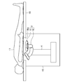
- FIG. 3 is a schematic diagram of the ultrasonic diagnostic treatment integrated system 1 and shows an example of a device configuration for diagnosing and treating a patient's trunk and the like.
- the figure is a schematic vertical sectional view, in which a water tank 19 is arranged under a bed 18 on which a patient 17 lies.
- the skin of the site to be diagnosed and treated by the patient 17 is in contact with the water surface of the water tank 19 through an opening 18 w provided in the bed 18, while the end effector 2 is disposed in the water of the water tank 19.
- the patient 17 and the end effector 2 are acoustically coupled with water.
- the end effector 2 can be moved three-dimensionally in the water by the moving mechanism 4.
- the ultrasonic probe 10 and the HIFU transducer 12 send out an ultrasonic wave according to a drive signal from the main body 6, and a reception signal of the ultrasonic probe 10 is sent to the main body 6. Note that transmission / reception of the two ultrasonic probes 10a and 10b and ultrasonic irradiation of the HIFU transducer 12 are performed in a time-sharing manner by the control unit 40, thereby avoiding mutual interference of ultrasonic waves.
- the main body 6 includes a transmission / reception circuit 20, a frame memory 22, a pulse generation circuit 24, a moving mechanism control unit 26, an arithmetic processing unit 28, a display unit 30, an input unit 32, and a storage unit 34.
- the main body 6 and each part thereof do not have to be a single device, and may be configured by being divided into a plurality of devices.
- the arithmetic processing unit 28 includes, for example, a processor such as a CPU (Central Processing Unit) and its peripheral circuits, and operates based on a program stored in the storage unit 34, and includes a control unit 40, an ultrasonic image generation unit 42, It functions as a learning unit 44 and a tracking processing unit 46.
- the learning unit 44 has functions as a reference setting unit 50 and a template generation unit 52.
- the transmission / reception circuit 20 performs transmission of ultrasonic waves from the ultrasonic probe 10 into the body and processing of echo signals received by the ultrasonic probe 10 according to control by the control unit 40. At the time of transmission, the transmission / reception circuit 20 generates a transmission pulse for exciting and driving each transducer of the transducer array and outputs the transmission pulse to the ultrasonic probe 10. The transmission / reception circuit 20 adjusts the amount of delay given to the transmission pulse for each transducer so that the ultrasound transmitted from the ultrasound probe 10 forms a transmission beam in a desired direction, and sets the excitation timing of each transducer. Control.
- the transmission / reception circuit 20 receives a reception signal for each of a plurality of transducers constituting the transducer array from the ultrasonic probe 10.
- the transmission / reception circuit 20 amplifies the reception signal of each transducer and then adjusts the phase difference of the reception signals between the transducers and performs a phasing addition process for adding together to form a reception beam.
- the transmission / reception circuit 20 converts the reception signal from an analog signal to a digital signal, and outputs the reception signal as an echo data string along the direction of the ultrasonic beam.
- An ultrasonic beam is electronically scanned by electronic scanning of the transducer array to form one scanning plane, and one frame of echo data is acquired from this scanning plane.
- the frame memory 22 stores an echo data string along the ultrasonic beam output from the transmission / reception circuit 20.
- the ultrasonic image generation unit 42 displays a tomographic image display from a transmission / reception coordinate system (circular coordinate system) specified by a scanning direction of an ultrasonic beam and a depth in the beam direction, from a spatial coordinate system in which echo data is defined.
- a B-mode image is generated as an ultrasonic image corresponding to the scanning surface of each of the ultrasonic probes 10a and 10b by converting into a two-dimensional orthogonal coordinate system suitable for the scanning method of the display unit 30 to be performed.
- the ultrasonic image generation unit 42 may generate an ultrasonic image of another expression method such as an M-mode image.
- the pulse generation circuit 24 generates and outputs a drive signal to the HIFU transducer 12 under the control of the control unit 40.
- the moving mechanism control unit 26 can control the moving mechanism 4 based on a control amount input from the outside, and performs, for example, three-dimensional position control. For example, error information between the tracking target position obtained from the ultrasonic image and the HIFU focus is input to the movement mechanism control unit 26.
- the moving mechanism control unit 26 grasps the current position of the end effector 2 from the value of the encoder of the motor of the moving mechanism 4 and determines the control amount to the motor together with the received error information.
- the control can be performed by, for example, proportional control (P control).
- the control unit 40 controls the operation of each unit of the system 1. For example, the control unit 40 controls the transmission / reception circuit 20 and the pulse generation circuit 24. Further, the control unit 40 can input the position of the site of interest obtained by the learning unit 44 or the tracking processing unit 46 to the movement mechanism control unit 26, and can move the end effector 2 according to the motion of the affected part, for example.
- the learning unit 44 corresponds to a feature information learning unit in the in-vivo motion tracking device according to the present invention. That is, the learning unit 44 uses the biological image in the motion cycle of the target region preceding the tracking process, learns the feature information representing the feature of the biological image in the target region corresponding to the target region, and generates the tracking feature information. .
- the attention area is an area set in the living body image corresponding to the attention area.
- the attention area corresponds to a region in which an operator such as a doctor or a laboratory technician is interested in observation or tracking, that is, a ROI (region of interest).
- the attention area can be designated by first operating the input section 32 by looking at the living body image displayed on the display section 30, for example, when the attention area is tracked.
- the area is the reference attention area, and the feature information in the reference attention area is the reference feature information.
- the reference setting unit 50 (or the reference setting unit 50, the display unit 30, and the input unit 32) functions as a reference setting unit that sets a reference attention area at a position that is a reference position on the trajectory of the attention portion. Specifically, when the operator designates an area on the biological image using the display unit 30 and the input unit 32, the reference setting unit 50 sets information for designating the area as information indicating the reference attention area. Further, the reference setting unit 50 determines the three-dimensional position in the living body of the designated area (or a point representing the designated area) according to the position of the end effector 2 and the position of the designated area in the ultrasonic image at that time. Is identified. This is set as a reference position on the orbit of the approximately periodic motion of the target region.
- the reference attention area can be set so as to include all of the attention areas such as the kidney and the liver, or can be set so as to include only a part thereof.
- the reference region of interest can be set so as to include the affected area and its surrounding tissue. Since the reference feature information is information serving as a reference for tracking, it is preferable that the reference attention area is set so that a anatomy suitable for tracking appears there.
- the template generation unit 52 is a feature information generation unit, and has a function of extracting reference feature information that is feature information in the reference attention area.
- the biological image is an ultrasonic image obtained by each of the ultrasonic probes 10a and 10b
- the feature information is an image pattern of an ultrasonic image cut out from the region of interest.
- the image pattern that is the feature information is referred to as a template.
- the target region is the kidney
- an image pattern in which the outline of the renal pelvis and the intravascular kidney and the kidney can be set as the reference feature information, that is, the reference template.
- the reference template that is, the reference template.
- the intravascular liver vessel, digestive tract An image pattern in which the diaphragm is reflected can be set.
- the template generation unit 52 tracks the attention area based on the reference feature information to obtain the trajectory of the attention site, and uses the feature information extracted from the tracked attention area to associate the tracking feature with the position on the trajectory. It has a function for obtaining information, that is, a tracking template. This function will be described later.
- the tracking processor 46 corresponds to the tracking processor in the in-vivo motion tracking device according to the present invention. That is, the tracking processing unit 46 searches the attention area based on the tracking feature information with the biological image that changes with time, and obtains the position of the attention area.
- the display unit 30 is an image display device such as a liquid crystal display, and displays a biological image such as an ultrasonic image, or displays a frame indicating a region of interest on the biological image.
- the input unit 32 is an input device such as a keyboard or a pointing device, and is used, for example, when an operator specifies a reference region of interest on a biological image.
- the storage unit 34 stores various programs and various data, and inputs / outputs such information to / from the arithmetic processing unit 28. For example, the position of the site of interest in the trajectory and the tracking template are associated with each other and stored in the storage unit 34, and read out and used in the region of interest tracking process.
- the periodicity of the movement of an organ such as an organ is not accurate but approximate, that is, approximately periodic.
- the repetition cycle of organ movement may fluctuate or a period of expansion and contraction may occur within the cycle, the above problem should be solved based on the premise that the organ will be at the same position every certain cycle. Has its limits.
- the shape of the organ and the surroundings of the organ are basically affected only by the position of the organ in the body. Therefore, if the organ position in the body is the same, the shape of the organ and the surroundings of the organ are also the same.
- the image pattern of an organ that moves approximately periodically is determined by the position on the orbit of the movement, and it can be expected that an image pattern with a high degree of similarity is obtained at the same position.
- the present invention makes use of this feature to learn an image pattern corresponding to the position at a plurality of positions on the trajectory of the movement of the target region prior to the organ tracking for the original diagnosis / treatment purpose.
- the image pattern is utilized to improve tracking accuracy and robustness.
- the learning of the image pattern in the present invention is based on the meaning that the image pattern for tracking is prepared in advance prior to the main tracking and the repeatability of the similar image pattern at the same position.
- the meaning of improving reliability is included.
- the ultrasonic image pattern basically changes continuously. Therefore, when obtaining the image pattern for tracking, in addition to the feature that the above-mentioned image pattern is determined by the organ position, the feature that the change of the image pattern is continuous is considered.
- the ultrasound diagnostic treatment integrated system 1 first obtains reference feature information from a reference attention area set by an operator for a diagnosis / treatment target person, and uses the reference feature information to draw attention of the subject.
- the learning operation for generating the tracking feature information of the part is executed, and then the main tracking operation of the attention site using the tracking feature information is started.
- the attention site is tracked using the reference feature information.
- the operator can select the reference feature information suitable for tracking when the feature of the attention site appears favorably, so that a certain degree of accuracy and robustness can be obtained even during tracking based on the reference feature information. The possibility of lost is reduced.
- the main tracking using the tracking feature information can improve accuracy and robustness compared with the tracking at the time of learning, and the operator can preferably perform diagnosis and treatment by the main tracking.
- FIG. 4 is a schematic processing flow diagram of the learning operation.
- the ultrasonic diagnostic treatment integrated system 1 When the ultrasonic diagnostic treatment integrated system 1 is activated, it starts generating an ultrasonic image by the ultrasonic probe 10 as a biological image.
- the operator can adjust the position of the target person or the position of the end effector 2 so that the region of interest can be tracked while monitoring the ultrasonic image obtained in real time.
- the operator sets an image area including the image pattern as a reference attention area at a timing at which an image pattern suitable for tracking the attention area appears in the ultrasonic image.
- the setting of the reference region of interest may be performed using an ultrasonic image obtained in real time or may be performed using a recorded ultrasonic image. Since the target region can basically move three-dimensionally, the reference target region is set for each of the ultrasonic images of the ultrasonic probes 10a and 10b so that the movement can be suitably tracked.
- the learning unit 44 sets the image pattern in the reference attention area as the reference template T 0 by the reference setting unit 50 (step S5), and the template generation unit 52 uses the reference template to recognize the attention area.
- the tracking process is started (step S10).
- the set reference template T 0 is stored in the storage unit 34 together with the position of the end effector 2, for example.
- Reference template T 0 tracking processing using is performed by template matching processing in the ultrasound image obtained sequentially F (t).
- t is time and F (t) is an ultrasonic image at time t.
- F (t) is updated at about 50 Hz.
- the i-th update time t referred to as t i.
- the template matching process the template is overlaid on the image to be searched for comparison and collation, and the similarity between the two is examined. Specifically moved by the learning portion 44 of the search target template T 0 ultrasound image F (t) above to detect the position of the most similarity is higher template defines the position and area of interest.
- the similarity evaluation scale includes the sum of absolute values of differences in luminance values (Sum of Absolute Difference: SAD), the sum of squares of differences in luminance values (Sum of Squared Difference: SSD), and the normalized correlation coefficient. Etc. are used.
- SAD Sum of Absolute Difference
- SSD Sum of Squared Difference
- Etc. a normalized correlation coefficient that is robust to linear conversion of the luminance value of an image is employed.
- the normalized correlation coefficient is 1 when the correlation degree of the image is the highest and -1 when the correlation degree is the lowest.
- the template generation unit 52 controls the moving mechanism 4 in accordance with the difference between the position of the attention area determined in the image F (t i ) and the position of the attention area determined at the previous time t i ⁇ 1.
- the effector 2 is moved following the region of interest.
- the template generation unit 52 calculates the shift of the center Q of the region of interest with respect to the focal point P of the focused ultrasonic wave shown in FIG. 2, and the control unit 40 drives the moving mechanism 4 by feedback control using the shift as an error, and ends.
- the effector 2 is moved.
- the template generation unit 52 tracks the attention area based on the reference template while moving the end effector 2.
- the template generation unit 52 obtains the trajectory of the attention site from the track of the tracked attention area.
- the trajectory can be defined based on the trajectory of the focal point P or the position of the end effector 2.
- the template generation unit 52 divides the trajectory of the site of interest observed by the system 1 into a plurality of sections, and extracts a section representative template as representative feature information from the attention area at a predetermined representative point in the section. To do.
- the trajectory is divided into m sections, and the j-th section is represented as S j .
- the intervals can be set at equal intervals or unequal intervals.
- a section is set on the trajectory within the range captured by the system 1. Further, since the region of interest moves approximately periodically, for example, it moves away from a certain position and returns to the original position. At that time, when the trajectory can be regarded as common for going and returning, a round trip section may be set in common.
- the body axis direction is defined as the x-axis
- the body left-right direction is defined as the y-axis
- the body front-rear direction is defined as the z-axis.
- the amount of movement of the kidney and liver in the x-axis direction is significantly larger than the amount of movement in the y- and z-axis directions.
- the image pattern of the site of interest is determined only by the amount of movement in the x-axis direction.
- the sections for the kidney and liver trajectories are set to be equally spaced in the x-axis direction.
- FIG. 5 is a schematic diagram of the trajectory 60 of the site of interest in the patient 17 on the bed 18. Since the movement along the trajectory 60 shown in the drawing is exclusively in the x-axis direction, an example is shown in which the trajectory 60 is divided into m sections S 1 to S m at equal intervals along the x-axis.
- the template generation unit 52 monitors whether or not the position of the region of interest being tracked reaches the boundary of the section (step S15), and when the section boundary is reached, the index j of the section is switched to the value of the section to enter from now on (step S15). S20). Then, it extracts the image pattern of the detected region of interest in the captured ultrasonic image newly entered segment S j as section representative template T * j (step S25). For example, T * j can be extracted from the ultrasonic image first taken in the section Sj .
- the template generation unit 52 performs the process of acquiring the section representative template for all sections, that is, for all indexes j (step S30).
- FIG. 6 is a schematic diagram of ultrasonic images in a plurality of sections.
- Ultrasound image 70a in FIG. 6 (a) shows an image of the organ 74 at the time set the reference region of interest 72 in section S alpha
- ultrasound image 70b in FIG. 6 (b) ultrasound image the 70a is an image of the organ 74 at different intervals S beta.
- Template generating unit 52 performs the template matching process in an ultrasound image 70b the image pattern of the reference target area 72 as a reference template T 0. Thereby, the attention area 76 is set in the ultrasonic image 70b, and the image pattern in the area is extracted as the section representative template T * ⁇ .
- the reliability of the section representative templates with an image pattern obtained in the section is higher it can be expected.
- the similarity between the observed ultrasound image pattern and the reference template T 0 becomes so low that stable template matching cannot be performed, and organ estimation based on the reference template T 0 is performed.
- a large error may occur in the position.
- the section representative template based on the image pattern obtained in the section has a low reliability.
- the template generation unit 52 continues to track the attention area using the reference template, and evaluates the reliability of the section representative template using the ultrasonic image pattern obtained a plurality of times in each section. Specifically, the template generation unit 52 determines which section S j the position where the ultrasonic image is taken belongs to (step S35), and uses the image pattern in the region of interest tracked in the ultrasonic image as a reference. template and compared to the respective section representative template of the segment S j, calculates a status value function Vold j and Vnew j for each m sections S j (step S40).
- the state value function Vold j is a value indicating the similarity between the image pattern of the attention area obtained in the section S j and T 0
- the state value function Vnew j is the image of the attention area obtained in the section S j . It is a value indicating the similarity between the pattern and T * j, and is defined by the following equations.
- ⁇ old j k is a correlation coefficient between the image pattern of the attention area obtained in the section S j and T 0
- ⁇ new j k is the image pattern of the attention area obtained in the section S j and T * j. Is the correlation coefficient.
- Each subscript k is an index for identifying a plurality of attention areas obtained in the section S j .
- the stay period in the section Sj of the target region may occur a plurality of times due to the approximately periodic motion of the target region.
- a plurality (n j ) of attention areas obtained in the section S j used for calculating Vold j and Vnew j are attention areas in all the ultrasonic images obtained in the stay period of the plurality of sections S j. be able to. As a result, an improvement in accuracy of Vold j and Vnew j can be expected. Further, in order to reduce the calculation load, Vold j and Vnew j are calculated by selecting the image pattern of the attention area by a predetermined number, for example, one by one in each of the stay periods of the plurality of sections S j. May be.
- the learning tracking operation by the learning unit 44 is terminated, for example, with the passage of a predetermined time (step S45).
- the time can be set to 30 seconds as an example.
- the end timing of the learning tracking operation is in the middle of the motion cycle of the target region, and the number of repetitions and the number nj of the sections may be different between the sections.
- the period of the learning tracking operation may be set with the movement cycle of the target region as a unit, and the number of repetitions in each section may be the same.
- the template generating unit 52 refers to the Vold j and Vnew j, define a tracing template T j for each section S j (S50).
- the template generation unit 52 uses the value Vnew j , which is a value indicating the similarity between the image pattern of the attention area in the section S j and the section representative template T * j , as the image pattern of the attention area in the section S j and the reference template T 0 . for at Vold j or a value indicating a degree of similarity of the section representative template T * j and tracking template T j of segment S j, if Vnew j is less than Vold j, tracking templates T j A tracking template for an adjacent section preceding the section S j is used.
- the tracking template can be defined by the following equation (3).
- Reference template T 0 is an image pattern you choose make sure that the person has appeared features of the site of interest, has received a direct check by the people. Therefore, suitable tracking can also be expected for the configuration in which tracking is performed by returning to the reference template outside the interval in which Vnew j is high.
- Vnew j and Vold j are equal, a predetermined one of T 0 or T * j is set as a tracking template T j .
- FIG. 7 is a schematic process flow diagram of the tracking operation.
- the tracking processing unit 46 starts the tracking operation.
- the tracking processor 46 searches the attention area based on the tracking template corresponding to the estimated position at the estimated position on the trajectory of the attention site, and obtains a new estimated position.
- the tracking processing unit 46 drives the moving mechanism 4 to move the end effector 2 so that the focus P of the focused ultrasound is adjusted to the estimated position of the attention area determined at time t i ⁇ 1 , and the time t Take an ultrasound image at i .
- the tracking processing unit 46 uses the tracking template corresponding to the position W (t i-1 ) on the trajectory of the attention area determined at the time t i-1 , and performs template matching processing using the new ultrasonic image. To search for a region of interest at time t i and find its new estimated position. That is, it is determined whether the position W (t i-1) is in which section of the track (step S100), if it is within the interval S j, the time based on the tracking template T j of segment S j t position W on the trajectory of the region of interest in the i seek (t i) (step S105).
- the tracking processing unit 46 repeatedly estimates the position of the region of interest using the tracking template corresponding to the position of the region of interest on the trajectory (S110), thereby tracking the region of interest moving in the living body.
- the feature information generation means in the present invention is different from the attention region in association with the position on the orbit by repeating tracking of the attention region based on the reference feature information for a plurality of motion cycles while acquiring the heartbeat information of the living body.
- Feature information at a plurality of heartbeat phases is extracted, and using the feature information, tracking feature information associated with a position on the trajectory is obtained for each of the plurality of heartbeat phases.
- the tracking processing unit searches the attention area based on the tracking feature information corresponding to the heartbeat phase at the time of acquiring the biological image, and obtains the position of the attention site.
- the template generation unit 52 acquires heart rate information obtained from a living body, and uses the heart rate information for the above-described tracking template learning operation.
- the heartbeat information is, for example, an output signal of an electrocardiograph, and includes information on the heartbeat phase ⁇ that changes with time t.
- This heart rate information may be input from the outside of the ultrasound diagnostic treatment integrated system 1, or a heart rate information acquisition device such as an electrocardiograph may be provided as a part of the ultrasound diagnostic treatment integrated system 1.
- the template generation unit 52 performs the learning tracking operation basically in the same manner as in the first embodiment by the template matching process using the reference template T 0 acquired at a certain heartbeat phase ⁇ 0 , and A section representative template is extracted in section Sj .
- the template generation unit 52 extracts section representative templates at a plurality of points (n ⁇ ) of heartbeat phases in each section S j .
- n ⁇ number of cardiac phase ⁇ ⁇ ( ⁇ 1,2,3, ... n ⁇ ) section representative template T * j of section S j at each, to extract the ⁇ . This corresponds to the processing up to step S30 in FIG. 4 in the first embodiment.
- the template generation unit 52 performs processing corresponding to steps S35 to S45 of FIG. 4 in the first embodiment.
- the subscript k is an index for identifying a plurality of attention areas obtained in the section S j as in the first embodiment.
- ⁇ new j by calculating the sum of k of lambda k, this state value at cardiac phase phi lambda to the interval S j function Vnew j, and lambda.
- ⁇ old j by calculating the sum of k of lambda k, the state value function Vold j in cardiac phase phi lambda this in the section S j, and lambda.
- the template generation unit 52 refers to Vold j, ⁇ and Vnew j, ⁇ by basically the same method as described in step S50 of FIG. 4 in the first embodiment, For each section S j , tracking templates T j and ⁇ are defined for each heartbeat phase ⁇ ⁇ .
- the obtained tracking template T j, ⁇ is stored in, for example, the storage unit 34 in association with the section in which it is obtained and the heartbeat phase.
- the tracking processing unit 46 performs this tracking operation basically in the same manner as the processing described with reference to FIG. 7 in the first embodiment.
- the tracking template T j, ⁇ is used.
- the tracking processing unit 46 reads a tracking template corresponding to the estimated position and the heartbeat phase from the storage unit 34 at the estimated position on the trajectory of the target region, and pays attention based on the tracking template.
- the region is searched and a new estimated position is obtained.
- the tracking processing unit 46 moves the end effector 2 following the estimated position of the attention area determined at time t i ⁇ 1 , and captures an ultrasonic image at time t i at that position.
- tracking processing unit 46 in the ultrasound image corresponding to the cardiac phase phi lambda at time t i-1 at the position on the trajectory of the attention area defined W (t i-1) at time t i
- a region of interest at time t i is searched for and a new estimated position is obtained. That is, it is determined whether the position W (t i-1) are in which zone the track, if it is within the interval S j, segment S j and cardiac phase ⁇ tracking templates corresponding to lambda T j, lambda Based on the above, the position W (t i ) of the region of interest on the trajectory at time t i is obtained.
- the tracking processing unit 46 repeatedly estimates the position of the region of interest using the tracking template corresponding to the position of the region of interest on the trajectory and the heartbeat phase at the time of imaging the ultrasonic image. Track the area of interest that moves.
- the difference between t i-1 and t i so basically small, the tracking templates using the ultrasound image at time t i instead corresponds to a cardiac phase at time t i the time
- the one corresponding to the heartbeat phase at t i ⁇ 1 that is, the one corresponding to the position of the region of interest and the heartbeat phase obtained at time t i ⁇ 1 can also be used.
- the present embodiment for example, it is possible to perform robust tracking not only with respect to a change in the image pattern due to the movement of the region of interest accompanying respiration, but also against a change in the image pattern due to the heartbeat.
- the kidney and the liver move in response to respiration, but the blood vessels in the liver also deform in response to the heartbeat. That is, the liver image may change under the influence of respiration and heartbeat.
- This embodiment is effective when such an organ is used as a site of interest.
- the reference template T 0 were those obtained at a certain cardiac phase.
- the operator may select a heartbeat phase at which a representative image pattern within the heartbeat cycle appears.
- the feature information generation unit extracts the reference feature information at each of a plurality of heartbeat phases, and switches the reference feature information used for tracking the attention area according to the heartbeat phase at the time of acquiring the biological image. Also good.
- the reference template is set in each n phi number of cardiac phases phi lambda.
- the operator sets a reference attention area at a certain heartbeat phase
- the template generation unit 52 extracts a reference template from the reference attention area of the ultrasonic image of the heartbeat phase, grasps the heartbeat phase from the heartbeat information, from cardiac phases are different ultrasound images to extract the reference template at the same reference region of interest n phi number of reference templates T 0, we obtain a lambda.
- the image pattern changes greatly with breathing while extracting the reference template at a plurality of heartbeat phases, for example, the subject temporarily stops breathing, and n ⁇ references in the meantime.
- Template generating unit 52 n phi number of reference templates T 0, performs the tracking behavior learning using lambda.
- the template generation unit 52 tracks the target site performs template matching by switching in accordance with the reference template cardiac phase at the time of acquisition of the ultrasound images at each interval S j of the track n phi number of cardiac phases phi ⁇ section representative template T * j for each, to extract the ⁇ .
- the template generation unit 52 uses T 0, Use ⁇ .
- the method of calculating ⁇ new j, ⁇ k , Vold j, ⁇ and Vnew j, ⁇ , and the method of defining the tracking template T j, ⁇ are as described above, and the operation of the tracking processing unit 46 is the same. is there.
- the accuracy of the reference template is increased, so that the accuracy of the section representative template is improved, and consequently the accuracy of the tracking template is increased. Therefore, tracking accuracy and robustness are further improved when the image pattern changes due to respiration and heartbeat.
- the living body image is a two-dimensional image using ultrasonic echoes.
- the living body image is not limited to this.
- the biological image may be a three-dimensional image, that is, a three-dimensional image.
- Various techniques for exploring the anatomy and forming an image can be used, such as X-ray fluoroscopy, computed tomography (CT), MRI, and positron emission tomography (Positron Emission).
- CT computed tomography
- MRI positron emission tomography
- PET positron emission tomography
- the image quality in the ultrasound image is generally not uniform, the focus position is optimal (or optimal), the resolution is high due to the high sound ray density, and the area where the image quality is high and the influence of noise and artifacts is low.
- Artifacts particularly when assuming HIFU treatment include acoustic shadows by the ribs and shielding by the lungs.
- the driving unit such as the moving mechanism 4 of the above-described embodiment is provided, and the imaging unit such as the ultrasonic probe 10 provided in the end effector 2 is moved along with the movement of the attention region, and the attention region is ultrasonic.
- a configuration in which an image is captured at a predetermined position where the image quality is relatively high is effective.
- a driving unit such as the moving mechanism 4 described above is provided, and an imaging unit such as the ultrasonic probe 10 provided in the end effector 2 is moved along with the movement of the region of interest.
- an imaging unit such as the ultrasonic probe 10 provided in the end effector 2 is moved along with the movement of the region of interest.
- an electronic follow-up such as image processing of biological image data without providing a mechanical follower like the moving mechanism 4.
- Follow-up can be performed by processing.
- the feature information representing the feature of the biological image of the region of interest may be a biological image as in the above-described embodiment, may be a feature amount extracted from the biological image, or the like in the tracking process.
- the identification of the region is not limited to the template matching method, and other methods such as an optical flow method and a neural network method may be used.
- the present invention is characterized by the tracking of tissues and organs that move approximately periodically in a living body, and it is not limited to which diagnostic device or therapeutic device this technology is used.
- the doctor manually changes the posture (or position) of the ultrasound probe manually in order to obtain information on the affected area outside the scan surface of the ultrasound probe. Observe the condition of the affected area. At this time, since the image of the affected part changes due to the change in the posture of the probe, the template becomes inappropriate and the possibility of failure in tracking increases.
- the present invention may be used as a means for solving this problem.
- the learning unit 44 generates a tracking template when the orientation of the probe changes due to the change in the orientation of the probe. Then, the posture (or position) in the posture (or position) orbit is detected by the posture (or position) sensor in the almost periodic posture (or position) change of the probe, and the organ movement is based on this information. As with the position in the orbit, switching robustness can be expected by switching the tracking template.
- the means for detecting the probe posture (or position) may be a robot encoder, or other posture (or position) measuring means such as a gyro sensor, an optical or magnetic posture (or position) sensor. Also good. Further, the above-mentioned change in the posture (or position) of the probe may be performed manually by a doctor or by a robot. Further, if the tracking template is switched by using the position in the motion trajectory of the organ and the posture (or position) in the posture (or position) orbit described above, an effect of further improving the robustness of the tracking can be expected.
- a treatment system for irradiating radiation following the movement of the affected area can be constructed.
- a system similar to the above can also be constructed in state-of-the-art cancer treatments such as proton beams, heavy particle beams, and neutron beams.
- the present invention when the present invention is applied to percutaneous ablation treatment, it is possible to construct a system for comparing and contrasting an ultrasonic image during treatment (or after treatment) and an ultrasonic image before treatment, and a coagulation margin is reduced. Since more accurate determination is possible, it is possible to more efficiently determine the end condition of treatment, and it is possible to improve treatment efficiency and low invasiveness.
- Other diagnostic imaging modalities X-ray, CT, MR, PET, etc.
- a master / slave manipulator system and incorporating the motion compensation of the site of interest according to the present invention into the drive control on the slave side, percutaneous ethanol injection treatment, percutaneous ablation treatment, puncture biopsy, etc.
- An apparatus that can be stably performed with high accuracy is realized.
- the above motion compensation can be expected to increase the autonomy of the slave manipulator with respect to the master manipulator.
- the above treatment can be stably and highly accurately performed on a local patient. In particular, it can be expected that the effect of increasing the autonomy of the slave manipulator will be relatively enhanced in an environment where communication time delay and signal waveform change between the master and slave are large.
- the detector is moved following the attention region, or electronic movement compensation of the obtained biological image data that changes with time is performed. By doing so, it is possible to acquire a biological image in which shaking is suppressed.
- the tracking template is stored in the storage unit 34 in association with the position on the trajectory by the learning operation.
- the treatment control information is further stored in association with the position on the trajectory, and control is performed in this tracking operation.
- the unit 40 can perform treatment control such as changing the intensity of the HIFU in conjunction with the follow-up of the treatment site.
- the treatment control information associated with the position can be set by the operator looking at the biological image obtained by the learning operation.
- the trajectory is actually divided into some sections, and the tracking feature information for each section
- the present invention is not essentially limited to the form in which the trajectory is divided into sections, and for example, the tracking feature information may be defined corresponding to the continuous position of the trajectory. .
Abstract
Grâce à la présente invention, il est possible d'améliorer la précision et la robustesse de suivi d'une partie d'intérêt qui se déplace à travers un corps vivant presque périodiquement. Une unité d'apprentissage (44) apprend des informations de caractéristiques indiquant une caractéristique d'une image de corps vivant dans une région d'intérêt correspondant à une partie d'intérêt, et génère des informations de caractéristique de suivi à l'aide d'une image de corps vivant dans une période de mouvement de la partie d'intérêt qui précède un traitement de suivi principal. Une unité de traitement de suivi (46) recherche la région d'intérêt sur la base des informations de caractéristique de suivi, dans l'image de corps vivant changeant au cours du temps, et détermine la position de la partie d'intérêt. L'unité d'apprentissage (44) établit une région d'intérêt de référence dans une position sur la base de la trajectoire de la partie d'intérêt. Une unité de génération de modèle (52) extrait des informations de caractéristique de référence qui sont des informations de caractéristique dans la région d'intérêt de référence, suit la région d'intérêt sur la base des informations de caractéristique de référence, et détermine une trajectoire et, à l'aide des informations de caractéristique extraites à partir de la région d'intérêt suivie, associe les informations de caractéristique avec une position sur la trajectoire et détermine des informations de caractéristique de suivi.
Applications Claiming Priority (2)
| Application Number | Priority Date | Filing Date | Title |
|---|---|---|---|
| JP2015040453A JP6489637B2 (ja) | 2015-03-02 | 2015-03-02 | 生体内運動追跡装置 |
| JP2015-040453 | 2015-03-02 |
Publications (1)
| Publication Number | Publication Date |
|---|---|
| WO2016139832A1 true WO2016139832A1 (fr) | 2016-09-09 |
Family
ID=56843708
Family Applications (1)
| Application Number | Title | Priority Date | Filing Date |
|---|---|---|---|
| PCT/JP2015/075132 WO2016139832A1 (fr) | 2015-03-02 | 2015-09-03 | Dispositif de suivi de mouvement in vivo |
Country Status (2)
| Country | Link |
|---|---|
| JP (1) | JP6489637B2 (fr) |
| WO (1) | WO2016139832A1 (fr) |
Cited By (2)
| Publication number | Priority date | Publication date | Assignee | Title |
|---|---|---|---|---|
| CN109963506A (zh) * | 2016-11-22 | 2019-07-02 | 西达-赛奈医疗中心 | 一种新型的转染和药物递送装置 |
| US10535159B2 (en) * | 2017-08-18 | 2020-01-14 | The University Of Electro-Communications | In vivo motion tracking device and in vivo motion tracking method |
Families Citing this family (4)
| Publication number | Priority date | Publication date | Assignee | Title |
|---|---|---|---|---|
| JP2018042900A (ja) * | 2016-09-16 | 2018-03-22 | 株式会社デンソー | ロボット装置 |
| US11083913B2 (en) | 2018-10-25 | 2021-08-10 | Elekta, Inc. | Machine learning approach to real-time patient motion monitoring |
| US10803987B2 (en) * | 2018-11-16 | 2020-10-13 | Elekta, Inc. | Real-time motion monitoring using deep neural network |
| JP7246952B2 (ja) * | 2019-02-12 | 2023-03-28 | キヤノンメディカルシステムズ株式会社 | 医用情報処理装置、x線診断装置及びプログラム |
Citations (5)
| Publication number | Priority date | Publication date | Assignee | Title |
|---|---|---|---|---|
| JP2007125152A (ja) * | 2005-11-02 | 2007-05-24 | Hitachi Medical Corp | 超音波診断装置 |
| WO2008044572A1 (fr) * | 2006-10-04 | 2008-04-17 | Hitachi Medical Corporation | dispositif de diagnostic d'images médicales |
| JP2010207427A (ja) * | 2009-03-11 | 2010-09-24 | Univ Of Tokyo | 生体内結石検出装置 |
| JP2010227603A (ja) * | 2010-06-16 | 2010-10-14 | Aloka Co Ltd | 超音波診断装置 |
| JP2011000470A (ja) * | 2010-10-01 | 2011-01-06 | Toshiba Corp | 超音波診断装置 |
-
2015
- 2015-03-02 JP JP2015040453A patent/JP6489637B2/ja active Active
- 2015-09-03 WO PCT/JP2015/075132 patent/WO2016139832A1/fr active Application Filing
Patent Citations (5)
| Publication number | Priority date | Publication date | Assignee | Title |
|---|---|---|---|---|
| JP2007125152A (ja) * | 2005-11-02 | 2007-05-24 | Hitachi Medical Corp | 超音波診断装置 |
| WO2008044572A1 (fr) * | 2006-10-04 | 2008-04-17 | Hitachi Medical Corporation | dispositif de diagnostic d'images médicales |
| JP2010207427A (ja) * | 2009-03-11 | 2010-09-24 | Univ Of Tokyo | 生体内結石検出装置 |
| JP2010227603A (ja) * | 2010-06-16 | 2010-10-14 | Aloka Co Ltd | 超音波診断装置 |
| JP2011000470A (ja) * | 2010-10-01 | 2011-01-06 | Toshiba Corp | 超音波診断装置 |
Cited By (5)
| Publication number | Priority date | Publication date | Assignee | Title |
|---|---|---|---|---|
| CN109963506A (zh) * | 2016-11-22 | 2019-07-02 | 西达-赛奈医疗中心 | 一种新型的转染和药物递送装置 |
| JP2020510452A (ja) * | 2016-11-22 | 2020-04-09 | シーダーズ−サイナイ メディカル センター | トランスフェクションおよび薬剤送達用の新規デバイス |
| US11413477B2 (en) | 2016-11-22 | 2022-08-16 | Cedars-Sinai Medical Center | Transfection and drug delivery |
| CN109963506B (zh) * | 2016-11-22 | 2024-05-07 | 西达-赛奈医疗中心 | 一种新型的转染和药物递送装置 |
| US10535159B2 (en) * | 2017-08-18 | 2020-01-14 | The University Of Electro-Communications | In vivo motion tracking device and in vivo motion tracking method |
Also Published As
| Publication number | Publication date |
|---|---|
| JP2016158890A (ja) | 2016-09-05 |
| JP6489637B2 (ja) | 2019-03-27 |
Similar Documents
| Publication | Publication Date | Title |
|---|---|---|
| JP6489637B2 (ja) | 生体内運動追跡装置 | |
| JP6675305B2 (ja) | エラストグラフィ測定システム及びその方法 | |
| JP5284123B2 (ja) | 超音波診断装置および位置情報取得プログラム | |
| JP6906113B2 (ja) | 周期的に動く生体構造を視覚化する装置、システム及び方法 | |
| US9747689B2 (en) | Image processing system, X-ray diagnostic apparatus, and image processing method | |
| US8882671B2 (en) | Ultrasonic diagnostic device, ultrasonic image processing apparatus, ultrasonic image acquiring method and ultrasonic diagnosis display method | |
| US20060241461A1 (en) | System and method for 3-D visualization of vascular structures using ultrasound | |
| US20160095573A1 (en) | Ultrasonic diagnostic apparatus | |
| CN109310399B (zh) | 医学超声图像处理设备 | |
| US20100198072A1 (en) | Ultrasonic diagnostic apparatus, ultrasonic image processing apparatus, medical image diagnostic apparatus, medical image processing apparatus, ultrasonic image processing method, and medical image processing method | |
| JP2010068904A (ja) | 超音波診断装置および画像表示プログラム | |
| KR20060112240A (ko) | 초음파를 사용하여 미리―획득한 이미지를 갖는전기해부학적 맵의 기록 | |
| JP7392093B2 (ja) | 超音波診断装置、及び制御プログラム | |
| KR20160076868A (ko) | 의료영상 장치, 영상 처리 장치 및 영상 융합 방법 | |
| US20100324420A1 (en) | Method and System for Imaging | |
| JP4468432B2 (ja) | 超音波診断装置 | |
| CN110868939A (zh) | 超声系统和方法 | |
| CN111225617A (zh) | 超声成像系统和方法 | |
| JP2010094181A (ja) | 超音波診断装置および超音波診断装置のデータ処理プログラム | |
| JP2008073423A (ja) | 超音波診断装置、診断パラメータ計測装置及び診断パラメータ計測方法 | |
| US10573009B2 (en) | In vivo movement tracking apparatus | |
| JP2011050625A (ja) | 処置支援システム | |
| JP5366372B2 (ja) | 超音波診断装置及び超音波画像データ生成プログラム | |
| JP2006146863A (ja) | 治療システム | |
| JP2009066409A (ja) | 位置情報に基づいて関心対象ボリュームを収集するための方法及びシステム |
Legal Events
| Date | Code | Title | Description |
|---|---|---|---|
| 121 | Ep: the epo has been informed by wipo that ep was designated in this application |
Ref document number: 15883998 Country of ref document: EP Kind code of ref document: A1 |
|
| NENP | Non-entry into the national phase |
Ref country code: DE |
|
| 122 | Ep: pct application non-entry in european phase |
Ref document number: 15883998 Country of ref document: EP Kind code of ref document: A1 |