WO2016139832A1 - In vivo movement tracking device - Google Patents
In vivo movement tracking device Download PDFInfo
- Publication number
- WO2016139832A1 WO2016139832A1 PCT/JP2015/075132 JP2015075132W WO2016139832A1 WO 2016139832 A1 WO2016139832 A1 WO 2016139832A1 JP 2015075132 W JP2015075132 W JP 2015075132W WO 2016139832 A1 WO2016139832 A1 WO 2016139832A1
- Authority
- WO
- WIPO (PCT)
- Prior art keywords
- feature information
- tracking
- interest
- region
- image
- Prior art date
Links
Images


Classifications
-
- A—HUMAN NECESSITIES
- A61—MEDICAL OR VETERINARY SCIENCE; HYGIENE
- A61B—DIAGNOSIS; SURGERY; IDENTIFICATION
- A61B8/00—Diagnosis using ultrasonic, sonic or infrasonic waves
- A61B8/08—Detecting organic movements or changes, e.g. tumours, cysts, swellings
Definitions
- the present invention relates to an in-vivo motion tracking device that tracks a region of interest that moves in a living body.
- High-intensity ultrasound is known in which powerful ultrasound is focused on cancer, tumors, etc., and cauterized to treat them (see Patent Document 1).
- treatment apparatuses for stones, prostate cancer, and liver cancer using HIFU have been developed and used.
- HIFU treatment it is desirable to grasp the position of the treatment site and focus a strong ultrasonic wave at that location so as not to damage normal tissues other than the treatment site such as cancer and tumor. For this reason, a system that focuses the therapeutic ultrasound on the position of the treatment site while confirming the position of the treatment site using a magnetic resonance image (Magnetic Resonance Imaging) or diagnostic ultrasound image has been used. Has been.
- the organs in the body can move by breathing or heartbeat.
- the liver can move 10 to 20 mm or more at a maximum speed of 15 to 20 mm / second with breathing, and can move 100 mm or more by deep breathing.
- the kidney moves on average 5 to 9 mm by respiration.
- HIFU such as kidney and liver, it is difficult to accurately irradiate ultrasonic waves following the movement of the organ in the living body, which is a barrier in treatment.
- the movement of the kidneys and liver causes changes in the relative position of the ribs, lungs, heart, gallbladder, and fascia around the organ and the deformation of the organ itself, thereby capturing the organ to be tracked
- Large changes occur in the image, eg, the ultrasound image pattern.
- the change in the image causes, for example, a failure in tracking by reducing the similarity between the template of the organ set as a tracking target in tracking by template matching and the image.
- the movement of organs in a living body is a problem in the treatment methods other than HIFU.
- HIFU cardiac surgery and lung cancer radiation therapy.
- the present invention has been made to solve the above-described problem, and an object thereof is to provide an in-vivo motion tracking device that suitably tracks a target region that moves in a living body.
- An in-vivo motion tracking apparatus is an apparatus that tracks a target region that moves in a living body in a periodic manner in a biological image obtained by imaging a living body structure, and the attention that precedes the main tracking process
- a feature information learning unit that learns about feature information representing features of the living body image in the attention area corresponding to the attention region using the living body image in the motion cycle of the portion and generates feature information for tracking, and changes with time
- a tracking processing unit that searches the region of interest based on the tracking feature information and obtains the position of the site of interest in the living body image, wherein the feature information learning unit includes a trajectory of the site of interest.
- Reference setting means for setting a reference region of interest at a position as the upper reference position, and reference feature information that is the feature information in the reference region of interest is extracted, and the region of interest is tracked based on the reference feature information Said With obtaining the road, using the feature information extracted from the region of interest was traced, having a feature information generating means for obtaining the tracking feature information in association with the position on the track.
- the feature information generation unit divides the trajectory into a plurality of sections, and the attention area at a predetermined representative point in the section in each section.
- Representative feature information is extracted from the reference feature information, the similarity between each of the reference feature information and the representative feature information and the feature information in the section of the attention area is calculated, and the similarity with respect to the representative feature information is the reference feature. If the similarity regarding the information is equal to or greater than the similarity, the representative feature information is the tracking feature information of the section, and if the similarity regarding the representative feature information is less than the similarity regarding the reference feature information, As the tracking feature information of the section, the tracking feature information of the adjacent section preceding the section can be used.
- the feature information generation unit divides the trajectory into a plurality of sections, and the attention area at a predetermined representative point in the section in each section.
- Representative feature information is extracted from the reference feature information and the representative feature information, and a feature having a higher similarity to the feature information in the section of the region of interest is used as the tracking feature information in the section. it can.
- the tracking processing unit has the tracking feature corresponding to the estimated position at the estimated position on the trajectory of the site of interest.
- a new estimated position may be obtained by searching the attention area based on information.
- the feature information generation unit tracks the region of interest based on the reference feature information for a plurality of motion cycles while acquiring heart beat information of the living body.
- the feature information at a plurality of different heartbeat phases is extracted from the region of interest in association with the position on the trajectory, and the tracking is associated with the position on the trajectory using the feature information.
- Feature information is obtained for each of the plurality of heartbeat phases, and the tracking processing unit searches the attention region based on the tracking feature information corresponding to the heartbeat phase at the time of acquiring the biological image, and the attention site. The position can be obtained.
- the feature information generation unit extracts the reference feature information at each of the plurality of heartbeat phases, and uses the reference feature information used for tracking the region of interest. You may switch according to the said heartbeat phase at the time of acquisition of the said biological image.
- the in-vivo motion tracking apparatus further includes an imaging unit that captures ultrasonic images on a plurality of cross-sectional planes that intersect each other as the biological image, and the region of interest includes the A drive unit that moves the imaging unit in accordance with the movement of the region of interest so as to appear at a predetermined position of each ultrasonic image, and the feature information is stored in the region of interest in each ultrasonic image. It can be configured as an image.
- the imaging unit can change a direction of the tomographic plane with respect to the living body, and the feature information learning unit changes the direction of the tomographic plane. Tracking feature information is generated, and the in-vivo motion tracking device includes means for detecting a change in the direction of the tomographic plane, and the tracking processing unit corresponds to the change in the direction of the tomographic plane in response to the change in the direction of the tomographic plane.
- the feature information can be switched to search for the region of interest.
- the present invention it is possible to suitably track a site of interest that moves approximately periodically in a living body in a living body image obtained by photographing a living body structure.
- FIG. 1 is a block diagram showing a schematic configuration of an ultrasonic diagnosis and treatment integration system according to a first embodiment of the present invention. It is a typical perspective view of the end effector used for the ultrasonic diagnostic treatment integrated system concerning a 1st embodiment of the present invention.
- 1 is a schematic diagram of an integrated system for ultrasonic diagnosis and treatment according to a first embodiment of the present invention. It is a processing flow figure of an outline of learning operation in an ultrasonic diagnostic treatment integrated system concerning a 1st embodiment of the present invention. It is a schematic diagram of the locus
- FIG. 3 is a schematic process flow diagram of the tracking operation in the ultrasonic diagnostic treatment integrated system according to the first embodiment of the present invention.
- the in-vivo motion tracking device is a device that tracks a region of interest that moves approximately periodically in a living body in a living body image obtained by photographing a living body structure.
- FIG. 1 is a block diagram showing a schematic configuration of an ultrasonic diagnosis and treatment integration system 1 according to the first embodiment.
- the ultrasonic diagnostic treatment integrated system 1 includes an end effector 2, a moving mechanism 4, and a main body 6, and includes an in-vivo motion tracking apparatus according to the present invention.
- the end effector 2 includes an ultrasonic probe 10 and a HIFU transducer 12, and is arranged toward a region of interest.
- the ultrasonic diagnostic treatment integrated system 1 can take an ultrasonic image as a living body image in real time by the ultrasonic probe 10, and the main body 6 tracks the position of the site of interest using the ultrasonic image.
- the moving mechanism 4 is controlled by the main body 6 and moves the end effector 2 three-dimensionally following the position of the target region.
- the ultrasonic diagnostic treatment integrated system 1 enables diagnosis of a site of interest using an ultrasonic image obtained by the ultrasonic probe 10, and can treat the affected part non-invasively by the HIFU method using the HIFU transducer 12.
- the attention site is, for example, a kidney or a liver. As described above, the kidney and liver move approximately periodically according to the respiration of a living body such as a patient.
- FIG. 2 is a schematic perspective view of the end effector 2.
- the ultrasonic probe 10 transmits ultrasonic pulses and receives echoes.
- the ultrasonic probe 10 has a transducer array, and an ultrasonic beam is formed by the transducer array and transmitted to the patient's body.
- the ultrasonic beam is electronically scanned in the array direction.
- the ultrasonic beam is transmitted in pulses, and the transducer array receives an echo from the body after the ultrasonic beam is transmitted.
- the two ultrasonic probes 10a and 10b basically make the scanning surfaces 13a and 13b orthogonal to each other so that the three-dimensional information of the target region can be acquired and the three-dimensional movement of the target region in the body can be handled.
- an ultrasonic biplane image is acquired as a living body image in which a structure of an internal organ or the like of the living body appears.
- the HIFU transducer 12 generates focused ultrasound for HIFU treatment.
- the HIFU transducer 12 includes a transducer array arranged so as to surround the ultrasonic probe 10a in an annular shape, and the transducer array forms a concave surface when viewed from the transmission direction of the ultrasonic waves.
- the positional relationship between the ultrasonic probes 10a and 10b and the HIFU transducer 12 is basically the intersection line 14 between the two scanning surfaces 13a and 13b of the ultrasonic probe 10 and the central axis 15 of the ring of the transducer array of the HIFU transducer 12. Is set so that the focal point of the focused ultrasonic wave is located at the intersection point P.
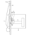
- FIG. 3 is a schematic diagram of the ultrasonic diagnostic treatment integrated system 1 and shows an example of a device configuration for diagnosing and treating a patient's trunk and the like.
- the figure is a schematic vertical sectional view, in which a water tank 19 is arranged under a bed 18 on which a patient 17 lies.
- the skin of the site to be diagnosed and treated by the patient 17 is in contact with the water surface of the water tank 19 through an opening 18 w provided in the bed 18, while the end effector 2 is disposed in the water of the water tank 19.
- the patient 17 and the end effector 2 are acoustically coupled with water.
- the end effector 2 can be moved three-dimensionally in the water by the moving mechanism 4.
- the ultrasonic probe 10 and the HIFU transducer 12 send out an ultrasonic wave according to a drive signal from the main body 6, and a reception signal of the ultrasonic probe 10 is sent to the main body 6. Note that transmission / reception of the two ultrasonic probes 10a and 10b and ultrasonic irradiation of the HIFU transducer 12 are performed in a time-sharing manner by the control unit 40, thereby avoiding mutual interference of ultrasonic waves.
- the main body 6 includes a transmission / reception circuit 20, a frame memory 22, a pulse generation circuit 24, a moving mechanism control unit 26, an arithmetic processing unit 28, a display unit 30, an input unit 32, and a storage unit 34.
- the main body 6 and each part thereof do not have to be a single device, and may be configured by being divided into a plurality of devices.
- the arithmetic processing unit 28 includes, for example, a processor such as a CPU (Central Processing Unit) and its peripheral circuits, and operates based on a program stored in the storage unit 34, and includes a control unit 40, an ultrasonic image generation unit 42, It functions as a learning unit 44 and a tracking processing unit 46.
- the learning unit 44 has functions as a reference setting unit 50 and a template generation unit 52.
- the transmission / reception circuit 20 performs transmission of ultrasonic waves from the ultrasonic probe 10 into the body and processing of echo signals received by the ultrasonic probe 10 according to control by the control unit 40. At the time of transmission, the transmission / reception circuit 20 generates a transmission pulse for exciting and driving each transducer of the transducer array and outputs the transmission pulse to the ultrasonic probe 10. The transmission / reception circuit 20 adjusts the amount of delay given to the transmission pulse for each transducer so that the ultrasound transmitted from the ultrasound probe 10 forms a transmission beam in a desired direction, and sets the excitation timing of each transducer. Control.
- the transmission / reception circuit 20 receives a reception signal for each of a plurality of transducers constituting the transducer array from the ultrasonic probe 10.
- the transmission / reception circuit 20 amplifies the reception signal of each transducer and then adjusts the phase difference of the reception signals between the transducers and performs a phasing addition process for adding together to form a reception beam.
- the transmission / reception circuit 20 converts the reception signal from an analog signal to a digital signal, and outputs the reception signal as an echo data string along the direction of the ultrasonic beam.
- An ultrasonic beam is electronically scanned by electronic scanning of the transducer array to form one scanning plane, and one frame of echo data is acquired from this scanning plane.
- the frame memory 22 stores an echo data string along the ultrasonic beam output from the transmission / reception circuit 20.
- the ultrasonic image generation unit 42 displays a tomographic image display from a transmission / reception coordinate system (circular coordinate system) specified by a scanning direction of an ultrasonic beam and a depth in the beam direction, from a spatial coordinate system in which echo data is defined.
- a B-mode image is generated as an ultrasonic image corresponding to the scanning surface of each of the ultrasonic probes 10a and 10b by converting into a two-dimensional orthogonal coordinate system suitable for the scanning method of the display unit 30 to be performed.
- the ultrasonic image generation unit 42 may generate an ultrasonic image of another expression method such as an M-mode image.
- the pulse generation circuit 24 generates and outputs a drive signal to the HIFU transducer 12 under the control of the control unit 40.
- the moving mechanism control unit 26 can control the moving mechanism 4 based on a control amount input from the outside, and performs, for example, three-dimensional position control. For example, error information between the tracking target position obtained from the ultrasonic image and the HIFU focus is input to the movement mechanism control unit 26.
- the moving mechanism control unit 26 grasps the current position of the end effector 2 from the value of the encoder of the motor of the moving mechanism 4 and determines the control amount to the motor together with the received error information.
- the control can be performed by, for example, proportional control (P control).
- the control unit 40 controls the operation of each unit of the system 1. For example, the control unit 40 controls the transmission / reception circuit 20 and the pulse generation circuit 24. Further, the control unit 40 can input the position of the site of interest obtained by the learning unit 44 or the tracking processing unit 46 to the movement mechanism control unit 26, and can move the end effector 2 according to the motion of the affected part, for example.
- the learning unit 44 corresponds to a feature information learning unit in the in-vivo motion tracking device according to the present invention. That is, the learning unit 44 uses the biological image in the motion cycle of the target region preceding the tracking process, learns the feature information representing the feature of the biological image in the target region corresponding to the target region, and generates the tracking feature information. .
- the attention area is an area set in the living body image corresponding to the attention area.
- the attention area corresponds to a region in which an operator such as a doctor or a laboratory technician is interested in observation or tracking, that is, a ROI (region of interest).
- the attention area can be designated by first operating the input section 32 by looking at the living body image displayed on the display section 30, for example, when the attention area is tracked.
- the area is the reference attention area, and the feature information in the reference attention area is the reference feature information.
- the reference setting unit 50 (or the reference setting unit 50, the display unit 30, and the input unit 32) functions as a reference setting unit that sets a reference attention area at a position that is a reference position on the trajectory of the attention portion. Specifically, when the operator designates an area on the biological image using the display unit 30 and the input unit 32, the reference setting unit 50 sets information for designating the area as information indicating the reference attention area. Further, the reference setting unit 50 determines the three-dimensional position in the living body of the designated area (or a point representing the designated area) according to the position of the end effector 2 and the position of the designated area in the ultrasonic image at that time. Is identified. This is set as a reference position on the orbit of the approximately periodic motion of the target region.
- the reference attention area can be set so as to include all of the attention areas such as the kidney and the liver, or can be set so as to include only a part thereof.
- the reference region of interest can be set so as to include the affected area and its surrounding tissue. Since the reference feature information is information serving as a reference for tracking, it is preferable that the reference attention area is set so that a anatomy suitable for tracking appears there.
- the template generation unit 52 is a feature information generation unit, and has a function of extracting reference feature information that is feature information in the reference attention area.
- the biological image is an ultrasonic image obtained by each of the ultrasonic probes 10a and 10b
- the feature information is an image pattern of an ultrasonic image cut out from the region of interest.
- the image pattern that is the feature information is referred to as a template.
- the target region is the kidney
- an image pattern in which the outline of the renal pelvis and the intravascular kidney and the kidney can be set as the reference feature information, that is, the reference template.
- the reference template that is, the reference template.
- the intravascular liver vessel, digestive tract An image pattern in which the diaphragm is reflected can be set.
- the template generation unit 52 tracks the attention area based on the reference feature information to obtain the trajectory of the attention site, and uses the feature information extracted from the tracked attention area to associate the tracking feature with the position on the trajectory. It has a function for obtaining information, that is, a tracking template. This function will be described later.
- the tracking processor 46 corresponds to the tracking processor in the in-vivo motion tracking device according to the present invention. That is, the tracking processing unit 46 searches the attention area based on the tracking feature information with the biological image that changes with time, and obtains the position of the attention area.
- the display unit 30 is an image display device such as a liquid crystal display, and displays a biological image such as an ultrasonic image, or displays a frame indicating a region of interest on the biological image.
- the input unit 32 is an input device such as a keyboard or a pointing device, and is used, for example, when an operator specifies a reference region of interest on a biological image.
- the storage unit 34 stores various programs and various data, and inputs / outputs such information to / from the arithmetic processing unit 28. For example, the position of the site of interest in the trajectory and the tracking template are associated with each other and stored in the storage unit 34, and read out and used in the region of interest tracking process.
- the periodicity of the movement of an organ such as an organ is not accurate but approximate, that is, approximately periodic.
- the repetition cycle of organ movement may fluctuate or a period of expansion and contraction may occur within the cycle, the above problem should be solved based on the premise that the organ will be at the same position every certain cycle. Has its limits.
- the shape of the organ and the surroundings of the organ are basically affected only by the position of the organ in the body. Therefore, if the organ position in the body is the same, the shape of the organ and the surroundings of the organ are also the same.
- the image pattern of an organ that moves approximately periodically is determined by the position on the orbit of the movement, and it can be expected that an image pattern with a high degree of similarity is obtained at the same position.
- the present invention makes use of this feature to learn an image pattern corresponding to the position at a plurality of positions on the trajectory of the movement of the target region prior to the organ tracking for the original diagnosis / treatment purpose.
- the image pattern is utilized to improve tracking accuracy and robustness.
- the learning of the image pattern in the present invention is based on the meaning that the image pattern for tracking is prepared in advance prior to the main tracking and the repeatability of the similar image pattern at the same position.
- the meaning of improving reliability is included.
- the ultrasonic image pattern basically changes continuously. Therefore, when obtaining the image pattern for tracking, in addition to the feature that the above-mentioned image pattern is determined by the organ position, the feature that the change of the image pattern is continuous is considered.
- the ultrasound diagnostic treatment integrated system 1 first obtains reference feature information from a reference attention area set by an operator for a diagnosis / treatment target person, and uses the reference feature information to draw attention of the subject.
- the learning operation for generating the tracking feature information of the part is executed, and then the main tracking operation of the attention site using the tracking feature information is started.
- the attention site is tracked using the reference feature information.
- the operator can select the reference feature information suitable for tracking when the feature of the attention site appears favorably, so that a certain degree of accuracy and robustness can be obtained even during tracking based on the reference feature information. The possibility of lost is reduced.
- the main tracking using the tracking feature information can improve accuracy and robustness compared with the tracking at the time of learning, and the operator can preferably perform diagnosis and treatment by the main tracking.
- FIG. 4 is a schematic processing flow diagram of the learning operation.
- the ultrasonic diagnostic treatment integrated system 1 When the ultrasonic diagnostic treatment integrated system 1 is activated, it starts generating an ultrasonic image by the ultrasonic probe 10 as a biological image.
- the operator can adjust the position of the target person or the position of the end effector 2 so that the region of interest can be tracked while monitoring the ultrasonic image obtained in real time.
- the operator sets an image area including the image pattern as a reference attention area at a timing at which an image pattern suitable for tracking the attention area appears in the ultrasonic image.
- the setting of the reference region of interest may be performed using an ultrasonic image obtained in real time or may be performed using a recorded ultrasonic image. Since the target region can basically move three-dimensionally, the reference target region is set for each of the ultrasonic images of the ultrasonic probes 10a and 10b so that the movement can be suitably tracked.
- the learning unit 44 sets the image pattern in the reference attention area as the reference template T 0 by the reference setting unit 50 (step S5), and the template generation unit 52 uses the reference template to recognize the attention area.
- the tracking process is started (step S10).
- the set reference template T 0 is stored in the storage unit 34 together with the position of the end effector 2, for example.
- Reference template T 0 tracking processing using is performed by template matching processing in the ultrasound image obtained sequentially F (t).
- t is time and F (t) is an ultrasonic image at time t.
- F (t) is updated at about 50 Hz.
- the i-th update time t referred to as t i.
- the template matching process the template is overlaid on the image to be searched for comparison and collation, and the similarity between the two is examined. Specifically moved by the learning portion 44 of the search target template T 0 ultrasound image F (t) above to detect the position of the most similarity is higher template defines the position and area of interest.
- the similarity evaluation scale includes the sum of absolute values of differences in luminance values (Sum of Absolute Difference: SAD), the sum of squares of differences in luminance values (Sum of Squared Difference: SSD), and the normalized correlation coefficient. Etc. are used.
- SAD Sum of Absolute Difference
- SSD Sum of Squared Difference
- Etc. a normalized correlation coefficient that is robust to linear conversion of the luminance value of an image is employed.
- the normalized correlation coefficient is 1 when the correlation degree of the image is the highest and -1 when the correlation degree is the lowest.
- the template generation unit 52 controls the moving mechanism 4 in accordance with the difference between the position of the attention area determined in the image F (t i ) and the position of the attention area determined at the previous time t i ⁇ 1.
- the effector 2 is moved following the region of interest.
- the template generation unit 52 calculates the shift of the center Q of the region of interest with respect to the focal point P of the focused ultrasonic wave shown in FIG. 2, and the control unit 40 drives the moving mechanism 4 by feedback control using the shift as an error, and ends.
- the effector 2 is moved.
- the template generation unit 52 tracks the attention area based on the reference template while moving the end effector 2.
- the template generation unit 52 obtains the trajectory of the attention site from the track of the tracked attention area.
- the trajectory can be defined based on the trajectory of the focal point P or the position of the end effector 2.
- the template generation unit 52 divides the trajectory of the site of interest observed by the system 1 into a plurality of sections, and extracts a section representative template as representative feature information from the attention area at a predetermined representative point in the section. To do.
- the trajectory is divided into m sections, and the j-th section is represented as S j .
- the intervals can be set at equal intervals or unequal intervals.
- a section is set on the trajectory within the range captured by the system 1. Further, since the region of interest moves approximately periodically, for example, it moves away from a certain position and returns to the original position. At that time, when the trajectory can be regarded as common for going and returning, a round trip section may be set in common.
- the body axis direction is defined as the x-axis
- the body left-right direction is defined as the y-axis
- the body front-rear direction is defined as the z-axis.
- the amount of movement of the kidney and liver in the x-axis direction is significantly larger than the amount of movement in the y- and z-axis directions.
- the image pattern of the site of interest is determined only by the amount of movement in the x-axis direction.
- the sections for the kidney and liver trajectories are set to be equally spaced in the x-axis direction.
- FIG. 5 is a schematic diagram of the trajectory 60 of the site of interest in the patient 17 on the bed 18. Since the movement along the trajectory 60 shown in the drawing is exclusively in the x-axis direction, an example is shown in which the trajectory 60 is divided into m sections S 1 to S m at equal intervals along the x-axis.
- the template generation unit 52 monitors whether or not the position of the region of interest being tracked reaches the boundary of the section (step S15), and when the section boundary is reached, the index j of the section is switched to the value of the section to enter from now on (step S15). S20). Then, it extracts the image pattern of the detected region of interest in the captured ultrasonic image newly entered segment S j as section representative template T * j (step S25). For example, T * j can be extracted from the ultrasonic image first taken in the section Sj .
- the template generation unit 52 performs the process of acquiring the section representative template for all sections, that is, for all indexes j (step S30).
- FIG. 6 is a schematic diagram of ultrasonic images in a plurality of sections.
- Ultrasound image 70a in FIG. 6 (a) shows an image of the organ 74 at the time set the reference region of interest 72 in section S alpha
- ultrasound image 70b in FIG. 6 (b) ultrasound image the 70a is an image of the organ 74 at different intervals S beta.
- Template generating unit 52 performs the template matching process in an ultrasound image 70b the image pattern of the reference target area 72 as a reference template T 0. Thereby, the attention area 76 is set in the ultrasonic image 70b, and the image pattern in the area is extracted as the section representative template T * ⁇ .
- the reliability of the section representative templates with an image pattern obtained in the section is higher it can be expected.
- the similarity between the observed ultrasound image pattern and the reference template T 0 becomes so low that stable template matching cannot be performed, and organ estimation based on the reference template T 0 is performed.
- a large error may occur in the position.
- the section representative template based on the image pattern obtained in the section has a low reliability.
- the template generation unit 52 continues to track the attention area using the reference template, and evaluates the reliability of the section representative template using the ultrasonic image pattern obtained a plurality of times in each section. Specifically, the template generation unit 52 determines which section S j the position where the ultrasonic image is taken belongs to (step S35), and uses the image pattern in the region of interest tracked in the ultrasonic image as a reference. template and compared to the respective section representative template of the segment S j, calculates a status value function Vold j and Vnew j for each m sections S j (step S40).
- the state value function Vold j is a value indicating the similarity between the image pattern of the attention area obtained in the section S j and T 0
- the state value function Vnew j is the image of the attention area obtained in the section S j . It is a value indicating the similarity between the pattern and T * j, and is defined by the following equations.
- ⁇ old j k is a correlation coefficient between the image pattern of the attention area obtained in the section S j and T 0
- ⁇ new j k is the image pattern of the attention area obtained in the section S j and T * j. Is the correlation coefficient.
- Each subscript k is an index for identifying a plurality of attention areas obtained in the section S j .
- the stay period in the section Sj of the target region may occur a plurality of times due to the approximately periodic motion of the target region.
- a plurality (n j ) of attention areas obtained in the section S j used for calculating Vold j and Vnew j are attention areas in all the ultrasonic images obtained in the stay period of the plurality of sections S j. be able to. As a result, an improvement in accuracy of Vold j and Vnew j can be expected. Further, in order to reduce the calculation load, Vold j and Vnew j are calculated by selecting the image pattern of the attention area by a predetermined number, for example, one by one in each of the stay periods of the plurality of sections S j. May be.
- the learning tracking operation by the learning unit 44 is terminated, for example, with the passage of a predetermined time (step S45).
- the time can be set to 30 seconds as an example.
- the end timing of the learning tracking operation is in the middle of the motion cycle of the target region, and the number of repetitions and the number nj of the sections may be different between the sections.
- the period of the learning tracking operation may be set with the movement cycle of the target region as a unit, and the number of repetitions in each section may be the same.
- the template generating unit 52 refers to the Vold j and Vnew j, define a tracing template T j for each section S j (S50).
- the template generation unit 52 uses the value Vnew j , which is a value indicating the similarity between the image pattern of the attention area in the section S j and the section representative template T * j , as the image pattern of the attention area in the section S j and the reference template T 0 . for at Vold j or a value indicating a degree of similarity of the section representative template T * j and tracking template T j of segment S j, if Vnew j is less than Vold j, tracking templates T j A tracking template for an adjacent section preceding the section S j is used.
- the tracking template can be defined by the following equation (3).
- Reference template T 0 is an image pattern you choose make sure that the person has appeared features of the site of interest, has received a direct check by the people. Therefore, suitable tracking can also be expected for the configuration in which tracking is performed by returning to the reference template outside the interval in which Vnew j is high.
- Vnew j and Vold j are equal, a predetermined one of T 0 or T * j is set as a tracking template T j .
- FIG. 7 is a schematic process flow diagram of the tracking operation.
- the tracking processing unit 46 starts the tracking operation.
- the tracking processor 46 searches the attention area based on the tracking template corresponding to the estimated position at the estimated position on the trajectory of the attention site, and obtains a new estimated position.
- the tracking processing unit 46 drives the moving mechanism 4 to move the end effector 2 so that the focus P of the focused ultrasound is adjusted to the estimated position of the attention area determined at time t i ⁇ 1 , and the time t Take an ultrasound image at i .
- the tracking processing unit 46 uses the tracking template corresponding to the position W (t i-1 ) on the trajectory of the attention area determined at the time t i-1 , and performs template matching processing using the new ultrasonic image. To search for a region of interest at time t i and find its new estimated position. That is, it is determined whether the position W (t i-1) is in which section of the track (step S100), if it is within the interval S j, the time based on the tracking template T j of segment S j t position W on the trajectory of the region of interest in the i seek (t i) (step S105).
- the tracking processing unit 46 repeatedly estimates the position of the region of interest using the tracking template corresponding to the position of the region of interest on the trajectory (S110), thereby tracking the region of interest moving in the living body.
- the feature information generation means in the present invention is different from the attention region in association with the position on the orbit by repeating tracking of the attention region based on the reference feature information for a plurality of motion cycles while acquiring the heartbeat information of the living body.
- Feature information at a plurality of heartbeat phases is extracted, and using the feature information, tracking feature information associated with a position on the trajectory is obtained for each of the plurality of heartbeat phases.
- the tracking processing unit searches the attention area based on the tracking feature information corresponding to the heartbeat phase at the time of acquiring the biological image, and obtains the position of the attention site.
- the template generation unit 52 acquires heart rate information obtained from a living body, and uses the heart rate information for the above-described tracking template learning operation.
- the heartbeat information is, for example, an output signal of an electrocardiograph, and includes information on the heartbeat phase ⁇ that changes with time t.
- This heart rate information may be input from the outside of the ultrasound diagnostic treatment integrated system 1, or a heart rate information acquisition device such as an electrocardiograph may be provided as a part of the ultrasound diagnostic treatment integrated system 1.
- the template generation unit 52 performs the learning tracking operation basically in the same manner as in the first embodiment by the template matching process using the reference template T 0 acquired at a certain heartbeat phase ⁇ 0 , and A section representative template is extracted in section Sj .
- the template generation unit 52 extracts section representative templates at a plurality of points (n ⁇ ) of heartbeat phases in each section S j .
- n ⁇ number of cardiac phase ⁇ ⁇ ( ⁇ 1,2,3, ... n ⁇ ) section representative template T * j of section S j at each, to extract the ⁇ . This corresponds to the processing up to step S30 in FIG. 4 in the first embodiment.
- the template generation unit 52 performs processing corresponding to steps S35 to S45 of FIG. 4 in the first embodiment.
- the subscript k is an index for identifying a plurality of attention areas obtained in the section S j as in the first embodiment.
- ⁇ new j by calculating the sum of k of lambda k, this state value at cardiac phase phi lambda to the interval S j function Vnew j, and lambda.
- ⁇ old j by calculating the sum of k of lambda k, the state value function Vold j in cardiac phase phi lambda this in the section S j, and lambda.
- the template generation unit 52 refers to Vold j, ⁇ and Vnew j, ⁇ by basically the same method as described in step S50 of FIG. 4 in the first embodiment, For each section S j , tracking templates T j and ⁇ are defined for each heartbeat phase ⁇ ⁇ .
- the obtained tracking template T j, ⁇ is stored in, for example, the storage unit 34 in association with the section in which it is obtained and the heartbeat phase.
- the tracking processing unit 46 performs this tracking operation basically in the same manner as the processing described with reference to FIG. 7 in the first embodiment.
- the tracking template T j, ⁇ is used.
- the tracking processing unit 46 reads a tracking template corresponding to the estimated position and the heartbeat phase from the storage unit 34 at the estimated position on the trajectory of the target region, and pays attention based on the tracking template.
- the region is searched and a new estimated position is obtained.
- the tracking processing unit 46 moves the end effector 2 following the estimated position of the attention area determined at time t i ⁇ 1 , and captures an ultrasonic image at time t i at that position.
- tracking processing unit 46 in the ultrasound image corresponding to the cardiac phase phi lambda at time t i-1 at the position on the trajectory of the attention area defined W (t i-1) at time t i
- a region of interest at time t i is searched for and a new estimated position is obtained. That is, it is determined whether the position W (t i-1) are in which zone the track, if it is within the interval S j, segment S j and cardiac phase ⁇ tracking templates corresponding to lambda T j, lambda Based on the above, the position W (t i ) of the region of interest on the trajectory at time t i is obtained.
- the tracking processing unit 46 repeatedly estimates the position of the region of interest using the tracking template corresponding to the position of the region of interest on the trajectory and the heartbeat phase at the time of imaging the ultrasonic image. Track the area of interest that moves.
- the difference between t i-1 and t i so basically small, the tracking templates using the ultrasound image at time t i instead corresponds to a cardiac phase at time t i the time
- the one corresponding to the heartbeat phase at t i ⁇ 1 that is, the one corresponding to the position of the region of interest and the heartbeat phase obtained at time t i ⁇ 1 can also be used.
- the present embodiment for example, it is possible to perform robust tracking not only with respect to a change in the image pattern due to the movement of the region of interest accompanying respiration, but also against a change in the image pattern due to the heartbeat.
- the kidney and the liver move in response to respiration, but the blood vessels in the liver also deform in response to the heartbeat. That is, the liver image may change under the influence of respiration and heartbeat.
- This embodiment is effective when such an organ is used as a site of interest.
- the reference template T 0 were those obtained at a certain cardiac phase.
- the operator may select a heartbeat phase at which a representative image pattern within the heartbeat cycle appears.
- the feature information generation unit extracts the reference feature information at each of a plurality of heartbeat phases, and switches the reference feature information used for tracking the attention area according to the heartbeat phase at the time of acquiring the biological image. Also good.
- the reference template is set in each n phi number of cardiac phases phi lambda.
- the operator sets a reference attention area at a certain heartbeat phase
- the template generation unit 52 extracts a reference template from the reference attention area of the ultrasonic image of the heartbeat phase, grasps the heartbeat phase from the heartbeat information, from cardiac phases are different ultrasound images to extract the reference template at the same reference region of interest n phi number of reference templates T 0, we obtain a lambda.
- the image pattern changes greatly with breathing while extracting the reference template at a plurality of heartbeat phases, for example, the subject temporarily stops breathing, and n ⁇ references in the meantime.
- Template generating unit 52 n phi number of reference templates T 0, performs the tracking behavior learning using lambda.
- the template generation unit 52 tracks the target site performs template matching by switching in accordance with the reference template cardiac phase at the time of acquisition of the ultrasound images at each interval S j of the track n phi number of cardiac phases phi ⁇ section representative template T * j for each, to extract the ⁇ .
- the template generation unit 52 uses T 0, Use ⁇ .
- the method of calculating ⁇ new j, ⁇ k , Vold j, ⁇ and Vnew j, ⁇ , and the method of defining the tracking template T j, ⁇ are as described above, and the operation of the tracking processing unit 46 is the same. is there.
- the accuracy of the reference template is increased, so that the accuracy of the section representative template is improved, and consequently the accuracy of the tracking template is increased. Therefore, tracking accuracy and robustness are further improved when the image pattern changes due to respiration and heartbeat.
- the living body image is a two-dimensional image using ultrasonic echoes.
- the living body image is not limited to this.
- the biological image may be a three-dimensional image, that is, a three-dimensional image.
- Various techniques for exploring the anatomy and forming an image can be used, such as X-ray fluoroscopy, computed tomography (CT), MRI, and positron emission tomography (Positron Emission).
- CT computed tomography
- MRI positron emission tomography
- PET positron emission tomography
- the image quality in the ultrasound image is generally not uniform, the focus position is optimal (or optimal), the resolution is high due to the high sound ray density, and the area where the image quality is high and the influence of noise and artifacts is low.
- Artifacts particularly when assuming HIFU treatment include acoustic shadows by the ribs and shielding by the lungs.
- the driving unit such as the moving mechanism 4 of the above-described embodiment is provided, and the imaging unit such as the ultrasonic probe 10 provided in the end effector 2 is moved along with the movement of the attention region, and the attention region is ultrasonic.
- a configuration in which an image is captured at a predetermined position where the image quality is relatively high is effective.
- a driving unit such as the moving mechanism 4 described above is provided, and an imaging unit such as the ultrasonic probe 10 provided in the end effector 2 is moved along with the movement of the region of interest.
- an imaging unit such as the ultrasonic probe 10 provided in the end effector 2 is moved along with the movement of the region of interest.
- an electronic follow-up such as image processing of biological image data without providing a mechanical follower like the moving mechanism 4.
- Follow-up can be performed by processing.
- the feature information representing the feature of the biological image of the region of interest may be a biological image as in the above-described embodiment, may be a feature amount extracted from the biological image, or the like in the tracking process.
- the identification of the region is not limited to the template matching method, and other methods such as an optical flow method and a neural network method may be used.
- the present invention is characterized by the tracking of tissues and organs that move approximately periodically in a living body, and it is not limited to which diagnostic device or therapeutic device this technology is used.
- the doctor manually changes the posture (or position) of the ultrasound probe manually in order to obtain information on the affected area outside the scan surface of the ultrasound probe. Observe the condition of the affected area. At this time, since the image of the affected part changes due to the change in the posture of the probe, the template becomes inappropriate and the possibility of failure in tracking increases.
- the present invention may be used as a means for solving this problem.
- the learning unit 44 generates a tracking template when the orientation of the probe changes due to the change in the orientation of the probe. Then, the posture (or position) in the posture (or position) orbit is detected by the posture (or position) sensor in the almost periodic posture (or position) change of the probe, and the organ movement is based on this information. As with the position in the orbit, switching robustness can be expected by switching the tracking template.
- the means for detecting the probe posture (or position) may be a robot encoder, or other posture (or position) measuring means such as a gyro sensor, an optical or magnetic posture (or position) sensor. Also good. Further, the above-mentioned change in the posture (or position) of the probe may be performed manually by a doctor or by a robot. Further, if the tracking template is switched by using the position in the motion trajectory of the organ and the posture (or position) in the posture (or position) orbit described above, an effect of further improving the robustness of the tracking can be expected.
- a treatment system for irradiating radiation following the movement of the affected area can be constructed.
- a system similar to the above can also be constructed in state-of-the-art cancer treatments such as proton beams, heavy particle beams, and neutron beams.
- the present invention when the present invention is applied to percutaneous ablation treatment, it is possible to construct a system for comparing and contrasting an ultrasonic image during treatment (or after treatment) and an ultrasonic image before treatment, and a coagulation margin is reduced. Since more accurate determination is possible, it is possible to more efficiently determine the end condition of treatment, and it is possible to improve treatment efficiency and low invasiveness.
- Other diagnostic imaging modalities X-ray, CT, MR, PET, etc.
- a master / slave manipulator system and incorporating the motion compensation of the site of interest according to the present invention into the drive control on the slave side, percutaneous ethanol injection treatment, percutaneous ablation treatment, puncture biopsy, etc.
- An apparatus that can be stably performed with high accuracy is realized.
- the above motion compensation can be expected to increase the autonomy of the slave manipulator with respect to the master manipulator.
- the above treatment can be stably and highly accurately performed on a local patient. In particular, it can be expected that the effect of increasing the autonomy of the slave manipulator will be relatively enhanced in an environment where communication time delay and signal waveform change between the master and slave are large.
- the detector is moved following the attention region, or electronic movement compensation of the obtained biological image data that changes with time is performed. By doing so, it is possible to acquire a biological image in which shaking is suppressed.
- the tracking template is stored in the storage unit 34 in association with the position on the trajectory by the learning operation.
- the treatment control information is further stored in association with the position on the trajectory, and control is performed in this tracking operation.
- the unit 40 can perform treatment control such as changing the intensity of the HIFU in conjunction with the follow-up of the treatment site.
- the treatment control information associated with the position can be set by the operator looking at the biological image obtained by the learning operation.
- the trajectory is actually divided into some sections, and the tracking feature information for each section
- the present invention is not essentially limited to the form in which the trajectory is divided into sections, and for example, the tracking feature information may be defined corresponding to the continuous position of the trajectory. .
Landscapes
- Life Sciences & Earth Sciences (AREA)
- Health & Medical Sciences (AREA)
- Medical Informatics (AREA)
- Biophysics (AREA)
- Nuclear Medicine, Radiotherapy & Molecular Imaging (AREA)
- Pathology (AREA)
- Radiology & Medical Imaging (AREA)
- Engineering & Computer Science (AREA)
- Biomedical Technology (AREA)
- Heart & Thoracic Surgery (AREA)
- Physics & Mathematics (AREA)
- Molecular Biology (AREA)
- Surgery (AREA)
- Animal Behavior & Ethology (AREA)
- General Health & Medical Sciences (AREA)
- Public Health (AREA)
- Veterinary Medicine (AREA)
- Ultra Sonic Daignosis Equipment (AREA)
- Image Analysis (AREA)
- Surgical Instruments (AREA)
Abstract
Through the present invention, it is possible to enhance the precision and robustness of tracking of a part of interest which moves through a living body almost periodically. A learning unit (44) learns feature information indicating a feature of a living body image in a region of interest corresponding to a part of interest and generates tracking feature information, using a living body image in a movement period of the part of interest which precedes main tracking processing. A tracking processing unit (46) searches the region of interest on the basis of the tracking feature information, in the living body image changing over time, and determines the position of the part of interest. The learning unit (44) sets a reference region of interest in a position based on the trajectory of the part of interest. A template generating unit (52) extracts reference feature information which is feature information in the reference region of interest, tracks the region of interest on the basis of the reference feature information and determines a trajectory, and, using the feature information extracted from the tracked region of interest, associates the feature information with a position on the trajectory and determines tracking feature information.
Description
本発明は生体内を運動する注目部位を追跡する生体内運動追跡装置に関する。
The present invention relates to an in-vivo motion tracking device that tracks a region of interest that moves in a living body.
癌や腫瘍などに強力な超音波を集束させてそれらを焼灼して治療する強力集束超音波(High Intensity Focused Ultrasound:HIFU)が知られている(特許文献1参照)。例えば、HIFUを採用した結石、前立腺癌、肝臓癌の治療用装置が開発され利用されている。
High-intensity ultrasound (HIFU) is known in which powerful ultrasound is focused on cancer, tumors, etc., and cauterized to treat them (see Patent Document 1). For example, treatment apparatuses for stones, prostate cancer, and liver cancer using HIFU have been developed and used.
HIFU治療では、癌や腫瘍などの治療箇所以外の正常な組織等を傷めないように、治療箇所の位置を把握してその位置に強力な超音波を集束させることが望ましい。そのため、従来から、核磁気共鳴画像(Magnetic Resonance Imaging:MRI)や診断用の超音波画像を利用して治療箇所の位置を確認しつつその位置に治療用の超音波を集束させるシステムなどが利用されている。
In HIFU treatment, it is desirable to grasp the position of the treatment site and focus a strong ultrasonic wave at that location so as not to damage normal tissues other than the treatment site such as cancer and tumor. For this reason, a system that focuses the therapeutic ultrasound on the position of the treatment site while confirming the position of the treatment site using a magnetic resonance image (Magnetic Resonance Imaging) or diagnostic ultrasound image has been used. Has been.
しかし、生体内の器官の多くは呼吸や心拍動により移動し得る。特に、肝臓は呼吸に伴い、最大15~20mm/秒の速度で10~20mm以上移動することや、深呼吸により100mm以上動き得ることが報告されている。また、腎臓は呼吸により平均で5~9mm移動すると報告されている。腎臓や肝臓などのHIFU治療ではこの生体内での臓器の運動に追従して正確に超音波を照射することが難しく、治療における障壁となっている。具体的には、腎臓や肝臓の運動は当該臓器周りの肋骨、肺、心臓、胆嚢、筋膜との相対位置関係の変化と臓器そのものの変形の原因となり、これによって追跡対象の臓器を捉えた像、例えば超音波画像パターンに大きな変化が生じる。当該像の変化は、例えば、テンプレートマッチングによる追跡に際して追跡対象として設定した臓器のテンプレートと当該像との類似度を減少させ、追跡失敗の原因となる。
However, many of the organs in the body can move by breathing or heartbeat. In particular, it has been reported that the liver can move 10 to 20 mm or more at a maximum speed of 15 to 20 mm / second with breathing, and can move 100 mm or more by deep breathing. It is also reported that the kidney moves on average 5 to 9 mm by respiration. In the treatment of HIFU such as kidney and liver, it is difficult to accurately irradiate ultrasonic waves following the movement of the organ in the living body, which is a barrier in treatment. Specifically, the movement of the kidneys and liver causes changes in the relative position of the ribs, lungs, heart, gallbladder, and fascia around the organ and the deformation of the organ itself, thereby capturing the organ to be tracked Large changes occur in the image, eg, the ultrasound image pattern. The change in the image causes, for example, a failure in tracking by reducing the similarity between the template of the organ set as a tracking target in tracking by template matching and the image.
また、生体内での器官の運動はHIFU以外の治療法においても問題となっている。例えば、心臓の外科手術や肺癌の放射線治療などである。
In addition, the movement of organs in a living body is a problem in the treatment methods other than HIFU. For example, cardiac surgery and lung cancer radiation therapy.
本発明は上記問題を解決するためになされたものであり、生体内を運動する注目部位を好適に追跡する生体内運動追跡装置を提供することを目的とする。
The present invention has been made to solve the above-described problem, and an object thereof is to provide an in-vivo motion tracking device that suitably tracks a target region that moves in a living body.
(1)本発明に係る生体内運動追跡装置は、生体内を概周期的に運動する注目部位を、生体構造を撮影した生体像において追跡する装置であって、本追跡処理に先行する前記注目部位の運動周期における前記生体像を用い、前記注目部位に対応する注目領域内の前記生体像の特徴を表す特徴情報について学習し追跡用特徴情報を生成する特徴情報学習部と、時間的に変化する前記生体像にて、前記追跡用特徴情報に基づいて前記注目領域を探索し前記注目部位の位置を求める本追跡処理部と、を有し、前記特徴情報学習部は、前記注目部位の軌道上の基準位置とする位置にて基準注目領域を設定する基準設定手段と、前記基準注目領域内の前記特徴情報である基準特徴情報を抽出し、当該基準特徴情報に基づき前記注目領域を追跡して前記軌道を求めると共に、追跡した前記注目領域から抽出した前記特徴情報を用いて、前記軌道上の位置に対応づけて前記追跡用特徴情報を求める特徴情報生成手段と、を有する。
(1) An in-vivo motion tracking apparatus according to the present invention is an apparatus that tracks a target region that moves in a living body in a periodic manner in a biological image obtained by imaging a living body structure, and the attention that precedes the main tracking process A feature information learning unit that learns about feature information representing features of the living body image in the attention area corresponding to the attention region using the living body image in the motion cycle of the portion and generates feature information for tracking, and changes with time A tracking processing unit that searches the region of interest based on the tracking feature information and obtains the position of the site of interest in the living body image, wherein the feature information learning unit includes a trajectory of the site of interest. Reference setting means for setting a reference region of interest at a position as the upper reference position, and reference feature information that is the feature information in the reference region of interest is extracted, and the region of interest is tracked based on the reference feature information Said With obtaining the road, using the feature information extracted from the region of interest was traced, having a feature information generating means for obtaining the tracking feature information in association with the position on the track.
(2)上記(1)の生体内運動追跡装置において、前記特徴情報生成手段は、前記軌道を複数の区間に区切り、当該各区間にて、当該区間における予め定めた代表点での前記注目領域から代表特徴情報を抽出し、前記基準特徴情報及び前記代表特徴情報のそれぞれと前記注目領域の当該区間における前記特徴情報との類似度を算出し、前記代表特徴情報に関する当該類似度が前記基準特徴情報に関する当該類似度以上である場合は、前記代表特徴情報を当該区間の前記追跡用特徴情報とし、前記代表特徴情報に関する当該類似度が前記基準特徴情報に関する当該類似度未満である場合は、当該区間の前記追跡用特徴情報として当該区間に先行する隣接区間の前記追跡用特徴情報を用いることができる。
(2) In the in-vivo motion tracking device according to (1), the feature information generation unit divides the trajectory into a plurality of sections, and the attention area at a predetermined representative point in the section in each section. Representative feature information is extracted from the reference feature information, the similarity between each of the reference feature information and the representative feature information and the feature information in the section of the attention area is calculated, and the similarity with respect to the representative feature information is the reference feature. If the similarity regarding the information is equal to or greater than the similarity, the representative feature information is the tracking feature information of the section, and if the similarity regarding the representative feature information is less than the similarity regarding the reference feature information, As the tracking feature information of the section, the tracking feature information of the adjacent section preceding the section can be used.
(3)上記(1)の生体内運動追跡装置において、前記特徴情報生成手段は、前記軌道を複数の区間に区切り、当該各区間にて、当該区間における予め定めた代表点での前記注目領域から代表特徴情報を抽出し、前記基準特徴情報と前記代表特徴情報とのうち前記注目領域の当該区間における前記特徴情報との類似度が高い方を当該区間の前記追跡用特徴情報とすることができる。
(3) In the in-vivo motion tracking device according to (1), the feature information generation unit divides the trajectory into a plurality of sections, and the attention area at a predetermined representative point in the section in each section. Representative feature information is extracted from the reference feature information and the representative feature information, and a feature having a higher similarity to the feature information in the section of the region of interest is used as the tracking feature information in the section. it can.
(4)上記(1)から(3)の生体内運動追跡装置において、前記本追跡処理部は、前記注目部位の前記軌道上での推定位置にて、当該推定位置に対応した前記追跡用特徴情報に基づいて前記注目領域を探索し新たな推定位置を求めてもよい。
(4) In the in-vivo motion tracking device according to (1) to (3), the tracking processing unit has the tracking feature corresponding to the estimated position at the estimated position on the trajectory of the site of interest. A new estimated position may be obtained by searching the attention area based on information.
(5)上記(1)の生体内運動追跡装置において、前記特徴情報生成手段は、前記生体の心拍情報を取得しつつ前記基準特徴情報に基づく前記注目領域の追跡を複数回の前記運動周期について繰り返すことによって、前記軌道上の位置に対応づけて前記注目領域から互いに異なる複数の心拍位相での前記特徴情報を抽出し、当該特徴情報を用いて、前記軌道上の位置に対応づけられる前記追跡用特徴情報を前記複数の心拍位相それぞれについて求め、前記本追跡処理部は、前記生体像の取得時の前記心拍位相に対応した前記追跡用特徴情報に基づいて前記注目領域を探索し前記注目部位の位置を求める構成とすることができる。
(5) In the in-vivo motion tracking device according to (1), the feature information generation unit tracks the region of interest based on the reference feature information for a plurality of motion cycles while acquiring heart beat information of the living body. By repeating, the feature information at a plurality of different heartbeat phases is extracted from the region of interest in association with the position on the trajectory, and the tracking is associated with the position on the trajectory using the feature information. Feature information is obtained for each of the plurality of heartbeat phases, and the tracking processing unit searches the attention region based on the tracking feature information corresponding to the heartbeat phase at the time of acquiring the biological image, and the attention site. The position can be obtained.
(6)上記(5)の生体内運動追跡装置において、前記特徴情報生成手段は、前記複数の心拍位相それぞれにて前記基準特徴情報を抽出し、前記注目領域の追跡に用いる前記基準特徴情報を前記生体像の取得時の前記心拍位相に応じて切り替えてもよい。
(6) In the in-vivo motion tracking device according to (5), the feature information generation unit extracts the reference feature information at each of the plurality of heartbeat phases, and uses the reference feature information used for tracking the region of interest. You may switch according to the said heartbeat phase at the time of acquisition of the said biological image.
(7)上記(1)から(6)の生体内運動追跡装置は、さらに、前記生体像として、互いに交差する複数の断層面での超音波画像を撮影する撮像部と、前記注目領域が前記各超音波画像の所定位置に写るように、前記注目領域の移動に伴って前記撮像部を移動させる駆動部と、を有し、前記特徴情報は、前記各超音波画像における前記注目領域内の画像である構成とすることができる。
(7) The in-vivo motion tracking apparatus according to (1) to (6) further includes an imaging unit that captures ultrasonic images on a plurality of cross-sectional planes that intersect each other as the biological image, and the region of interest includes the A drive unit that moves the imaging unit in accordance with the movement of the region of interest so as to appear at a predetermined position of each ultrasonic image, and the feature information is stored in the region of interest in each ultrasonic image. It can be configured as an image.
(8)上記(7)の生体内運動追跡装置において、前記撮像部は前記生体に対する前記断層面の向きを変えることができ、前記特徴情報学習部は前記断層面の向きを変えたときの前記追跡用特徴情報を生成し、当該生体内運動追跡装置は前記断層面の向きの変化を検知する手段を備え、前記本追跡処理部は、前記断層面の向きの変化に対応して前記追跡用特徴情報を切り替えて前記注目領域を探索する構成とすることができる。
(8) In the in-vivo motion tracking device according to (7), the imaging unit can change a direction of the tomographic plane with respect to the living body, and the feature information learning unit changes the direction of the tomographic plane. Tracking feature information is generated, and the in-vivo motion tracking device includes means for detecting a change in the direction of the tomographic plane, and the tracking processing unit corresponds to the change in the direction of the tomographic plane in response to the change in the direction of the tomographic plane. The feature information can be switched to search for the region of interest.
本発明によれば、生体内を概周期的に運動する注目部位を、生体構造を撮影した生体像において好適に追跡することが可能となる。
According to the present invention, it is possible to suitably track a site of interest that moves approximately periodically in a living body in a living body image obtained by photographing a living body structure.
以下、本発明に係る生体内運動追跡装置の実施の形態(以下実施形態という)について、図面に基づいて説明する。当該生体内運動追跡装置は、生体内を概周期的に運動する注目部位を、生体構造を撮影した生体像において追跡する装置である。
Hereinafter, an embodiment (hereinafter referred to as an embodiment) of an in-vivo motion tracking apparatus according to the present invention will be described based on the drawings. The in-vivo motion tracking device is a device that tracks a region of interest that moves approximately periodically in a living body in a living body image obtained by photographing a living body structure.
[第1の実施形態]
図1は第1の実施形態に係る超音波診断治療統合システム1の概略の構成を示すブロック図である。超音波診断治療統合システム1はエンドエフェクタ2、移動機構4及び本体6からなり、また本発明に係る生体内運動追跡装置を含んで構成される。エンドエフェクタ2は超音波プローブ10とHIFUトランスデューサ12とを備え、注目部位に向けて配置される。超音波診断治療統合システム1は超音波プローブ10により生体像として超音波画像をリアルタイムに撮影することができ、本体6は当該超音波画像を用いて注目部位の位置を追跡する。移動機構4は本体6により制御され、注目部位の位置に追従してエンドエフェクタ2を3次元的に移動させる。超音波診断治療統合システム1は超音波プローブ10により得られる超音波画像を用いて注目部位の診断を可能とし、また、HIFUトランスデューサ12により患部をHIFU法により非侵襲に治療することができる。ここでは注目部位は例えば腎臓や肝臓であるとする。腎臓や肝臓は既に述べたように、患者等、生体の呼吸に応じて概周期的に運動する。 [First Embodiment]
FIG. 1 is a block diagram showing a schematic configuration of an ultrasonic diagnosis andtreatment integration system 1 according to the first embodiment. The ultrasonic diagnostic treatment integrated system 1 includes an end effector 2, a moving mechanism 4, and a main body 6, and includes an in-vivo motion tracking apparatus according to the present invention. The end effector 2 includes an ultrasonic probe 10 and a HIFU transducer 12, and is arranged toward a region of interest. The ultrasonic diagnostic treatment integrated system 1 can take an ultrasonic image as a living body image in real time by the ultrasonic probe 10, and the main body 6 tracks the position of the site of interest using the ultrasonic image. The moving mechanism 4 is controlled by the main body 6 and moves the end effector 2 three-dimensionally following the position of the target region. The ultrasonic diagnostic treatment integrated system 1 enables diagnosis of a site of interest using an ultrasonic image obtained by the ultrasonic probe 10, and can treat the affected part non-invasively by the HIFU method using the HIFU transducer 12. Here, it is assumed that the attention site is, for example, a kidney or a liver. As described above, the kidney and liver move approximately periodically according to the respiration of a living body such as a patient.
図1は第1の実施形態に係る超音波診断治療統合システム1の概略の構成を示すブロック図である。超音波診断治療統合システム1はエンドエフェクタ2、移動機構4及び本体6からなり、また本発明に係る生体内運動追跡装置を含んで構成される。エンドエフェクタ2は超音波プローブ10とHIFUトランスデューサ12とを備え、注目部位に向けて配置される。超音波診断治療統合システム1は超音波プローブ10により生体像として超音波画像をリアルタイムに撮影することができ、本体6は当該超音波画像を用いて注目部位の位置を追跡する。移動機構4は本体6により制御され、注目部位の位置に追従してエンドエフェクタ2を3次元的に移動させる。超音波診断治療統合システム1は超音波プローブ10により得られる超音波画像を用いて注目部位の診断を可能とし、また、HIFUトランスデューサ12により患部をHIFU法により非侵襲に治療することができる。ここでは注目部位は例えば腎臓や肝臓であるとする。腎臓や肝臓は既に述べたように、患者等、生体の呼吸に応じて概周期的に運動する。 [First Embodiment]
FIG. 1 is a block diagram showing a schematic configuration of an ultrasonic diagnosis and
図2はエンドエフェクタ2の模式的な斜視図である。超音波プローブ10は超音波パルスの送出及びエコーの受波を行う。具体的には超音波プローブ10は振動子アレイを有し、振動子アレイにより超音波ビームを形成し患者の体内へ送出する。超音波ビームは電子的にアレイ方向に走査される。超音波ビームの送出はパルス状に行われ、振動子アレイは超音波ビームの送出後、体内からのエコーを受波する。注目部位の3次元情報を取得し、また体内での注目部位の3次元的な移動に対応できるように、2つの超音波プローブ10a,10bが互いの走査面13a,13bを基本的に直交させてエンドエフェクタ2に配置される。よって、生体の体内の器官等の構造が現れる生体像として超音波のバイプレーン画像が取得される。
FIG. 2 is a schematic perspective view of the end effector 2. The ultrasonic probe 10 transmits ultrasonic pulses and receives echoes. Specifically, the ultrasonic probe 10 has a transducer array, and an ultrasonic beam is formed by the transducer array and transmitted to the patient's body. The ultrasonic beam is electronically scanned in the array direction. The ultrasonic beam is transmitted in pulses, and the transducer array receives an echo from the body after the ultrasonic beam is transmitted. The two ultrasonic probes 10a and 10b basically make the scanning surfaces 13a and 13b orthogonal to each other so that the three-dimensional information of the target region can be acquired and the three-dimensional movement of the target region in the body can be handled. To the end effector 2. Therefore, an ultrasonic biplane image is acquired as a living body image in which a structure of an internal organ or the like of the living body appears.
HIFUトランスデューサ12はHIFU治療のための集束超音波を発生する。例えば、HIFUトランスデューサ12は超音波プローブ10aを円環状に取り囲むように配列された振動子アレイを備え、その振動子アレイは超音波の送出方向から見て凹面を形成する。超音波プローブ10a,10b及びHIFUトランスデューサ12の位置関係は基本的には超音波プローブ10の2つの走査面13a,13bの交線14と、HIFUトランスデューサ12の振動子アレイの円環の中心軸15との交点Pに集束超音波の焦点が位置するように設定されている。
HIFU transducer 12 generates focused ultrasound for HIFU treatment. For example, the HIFU transducer 12 includes a transducer array arranged so as to surround the ultrasonic probe 10a in an annular shape, and the transducer array forms a concave surface when viewed from the transmission direction of the ultrasonic waves. The positional relationship between the ultrasonic probes 10a and 10b and the HIFU transducer 12 is basically the intersection line 14 between the two scanning surfaces 13a and 13b of the ultrasonic probe 10 and the central axis 15 of the ring of the transducer array of the HIFU transducer 12. Is set so that the focal point of the focused ultrasonic wave is located at the intersection point P.
図3は超音波診断治療統合システム1の模式図であり、患者の体幹部等の診断・治療を行う装置構成の例を示している。図は模式的な垂直断面図であり、患者17が横たわるベッド18の下に水槽19が配置される。患者17の診断・治療対象の部位の皮膚はベッド18に設けられた開口部18wにて水槽19の水面に接し、一方、エンドエフェクタ2は水槽19の水中内に配置される。これにより患者17とエンドエフェクタ2との間が水で音響的にカップリングされる。エンドエフェクタ2は移動機構4により水中内を3次元的に移動可能である。
FIG. 3 is a schematic diagram of the ultrasonic diagnostic treatment integrated system 1 and shows an example of a device configuration for diagnosing and treating a patient's trunk and the like. The figure is a schematic vertical sectional view, in which a water tank 19 is arranged under a bed 18 on which a patient 17 lies. The skin of the site to be diagnosed and treated by the patient 17 is in contact with the water surface of the water tank 19 through an opening 18 w provided in the bed 18, while the end effector 2 is disposed in the water of the water tank 19. As a result, the patient 17 and the end effector 2 are acoustically coupled with water. The end effector 2 can be moved three-dimensionally in the water by the moving mechanism 4.
超音波プローブ10及びHIFUトランスデューサ12は、本体6からの駆動信号に応じて超音波を送出し、また超音波プローブ10の受信信号は本体6へ送られる。なお、2つの超音波プローブ10a,10bの送受波及びHIFUトランスデューサ12の超音波照射は制御部40により時分割で行われ、これにより互いの超音波の干渉を避けることができる。
The ultrasonic probe 10 and the HIFU transducer 12 send out an ultrasonic wave according to a drive signal from the main body 6, and a reception signal of the ultrasonic probe 10 is sent to the main body 6. Note that transmission / reception of the two ultrasonic probes 10a and 10b and ultrasonic irradiation of the HIFU transducer 12 are performed in a time-sharing manner by the control unit 40, thereby avoiding mutual interference of ultrasonic waves.
本体6は送受波回路20、フレームメモリ22、パルス発生回路24、移動機構制御部26、演算処理部28、表示部30、入力部32、記憶部34を含んで構成されている。ちなみに、本体6及びその各部は単一の装置である必要はなく、複数の装置に分かれて構成されていてもよい。
The main body 6 includes a transmission / reception circuit 20, a frame memory 22, a pulse generation circuit 24, a moving mechanism control unit 26, an arithmetic processing unit 28, a display unit 30, an input unit 32, and a storage unit 34. Incidentally, the main body 6 and each part thereof do not have to be a single device, and may be configured by being divided into a plurality of devices.
演算処理部28は例えば、CPU(Central Processing Unit)等のプロセッサ及びその周辺回路で構成され、記憶部34に格納されたプログラム等に基づいて動作し、制御部40、超音波画像生成部42、学習部44、追跡処理部46として機能する。学習部44は基準設定部50及びテンプレート生成部52としての機能を有する。
The arithmetic processing unit 28 includes, for example, a processor such as a CPU (Central Processing Unit) and its peripheral circuits, and operates based on a program stored in the storage unit 34, and includes a control unit 40, an ultrasonic image generation unit 42, It functions as a learning unit 44 and a tracking processing unit 46. The learning unit 44 has functions as a reference setting unit 50 and a template generation unit 52.
送受波回路20は制御部40による制御に従って、超音波プローブ10から体内への超音波の送信、及び超音波プローブ10が受信したエコー信号の処理を行う。送信時には、送受波回路20は、振動子アレイの各振動子を励振駆動するための送信パルスを生成し超音波プローブ10へ出力する。送受波回路20は、超音波プローブ10から送信される超音波が所望の方向に送信ビームを形成するように、送信パルスに与える遅延量を振動子ごとに調整して各振動子の励振タイミングを制御する。
The transmission / reception circuit 20 performs transmission of ultrasonic waves from the ultrasonic probe 10 into the body and processing of echo signals received by the ultrasonic probe 10 according to control by the control unit 40. At the time of transmission, the transmission / reception circuit 20 generates a transmission pulse for exciting and driving each transducer of the transducer array and outputs the transmission pulse to the ultrasonic probe 10. The transmission / reception circuit 20 adjusts the amount of delay given to the transmission pulse for each transducer so that the ultrasound transmitted from the ultrasound probe 10 forms a transmission beam in a desired direction, and sets the excitation timing of each transducer. Control.
一方、受信時には、送受波回路20は超音波プローブ10から振動子アレイを構成する複数の振動子ごとの受信信号を入力される。送受波回路20は各振動子の受信信号を増幅した後、振動子間の受信信号の位相差を調整して互いに加算する整相加算処理を行って受信ビームを形成する。また、送受波回路20は、受信信号をアナログ信号からデジタル信号に変換し、受信信号を超音波ビームの方向に沿ったエコーデータ列として出力する。
On the other hand, at the time of reception, the transmission / reception circuit 20 receives a reception signal for each of a plurality of transducers constituting the transducer array from the ultrasonic probe 10. The transmission / reception circuit 20 amplifies the reception signal of each transducer and then adjusts the phase difference of the reception signals between the transducers and performs a phasing addition process for adding together to form a reception beam. The transmission / reception circuit 20 converts the reception signal from an analog signal to a digital signal, and outputs the reception signal as an echo data string along the direction of the ultrasonic beam.
振動子アレイの電子走査によって超音波ビームが電子的に走査されることによって一つの走査面が形成され、この走査面から1フレームのエコーデータが取得される。フレームメモリ22は送受波回路20から出力される超音波ビームに沿ったエコーデータ列を格納する。
An ultrasonic beam is electronically scanned by electronic scanning of the transducer array to form one scanning plane, and one frame of echo data is acquired from this scanning plane. The frame memory 22 stores an echo data string along the ultrasonic beam output from the transmission / reception circuit 20.
超音波画像生成部42は、エコーデータが定義される空間座標系を、超音波ビームの走査方向とビーム方向の深さとで指定される送受波座標系(円座標系)から、断層画像表示を行う表示部30の走査方式に適合した2次元直交座標系に変換し、これにより超音波プローブ10a,10bそれぞれの走査面に対応した超音波画像として例えばBモード画像を生成する。なお、超音波画像生成部42はMモード画像など他の表現方式の超音波画像を生成してもよい。
The ultrasonic image generation unit 42 displays a tomographic image display from a transmission / reception coordinate system (circular coordinate system) specified by a scanning direction of an ultrasonic beam and a depth in the beam direction, from a spatial coordinate system in which echo data is defined. For example, a B-mode image is generated as an ultrasonic image corresponding to the scanning surface of each of the ultrasonic probes 10a and 10b by converting into a two-dimensional orthogonal coordinate system suitable for the scanning method of the display unit 30 to be performed. Note that the ultrasonic image generation unit 42 may generate an ultrasonic image of another expression method such as an M-mode image.
パルス発生回路24は制御部40の制御に従い、HIFUトランスデューサ12への駆動信号を生成し出力する。
The pulse generation circuit 24 generates and outputs a drive signal to the HIFU transducer 12 under the control of the control unit 40.
移動機構制御部26は外部から入力される制御量に基づいて移動機構4を制御することができ、例えば、3次元の位置制御を行う。例えば、超音波画像から得られる追従対象の位置とHIFU焦点との誤差情報が移動機構制御部26に入力される。移動機構制御部26は移動機構4のモータのエンコーダの値から現在のエンドエフェクタ2の位置を把握し、受け取った誤差情報と併せてモータへの制御量を決定する。当該制御は例えば、比例制御(P制御)で行うことができる。
The moving mechanism control unit 26 can control the moving mechanism 4 based on a control amount input from the outside, and performs, for example, three-dimensional position control. For example, error information between the tracking target position obtained from the ultrasonic image and the HIFU focus is input to the movement mechanism control unit 26. The moving mechanism control unit 26 grasps the current position of the end effector 2 from the value of the encoder of the motor of the moving mechanism 4 and determines the control amount to the motor together with the received error information. The control can be performed by, for example, proportional control (P control).
制御部40は本システム1の各部の動作を制御する。例えば、制御部40は送受波回路20やパルス発生回路24を制御する。また制御部40は、学習部44や追跡処理部46により得られる注目部位の位置を移動機構制御部26に入力し、例えば、患部の運動に応じてエンドエフェクタ2を移動させることができる。
The control unit 40 controls the operation of each unit of the system 1. For example, the control unit 40 controls the transmission / reception circuit 20 and the pulse generation circuit 24. Further, the control unit 40 can input the position of the site of interest obtained by the learning unit 44 or the tracking processing unit 46 to the movement mechanism control unit 26, and can move the end effector 2 according to the motion of the affected part, for example.
学習部44は本発明に係る生体内運動追跡装置における特徴情報学習部に相当する。すなわち、学習部44は本追跡処理に先行する注目部位の運動周期における生体像を用い、注目部位に対応する注目領域内の生体像の特徴を表す特徴情報について学習し追跡用特徴情報を生成する。
The learning unit 44 corresponds to a feature information learning unit in the in-vivo motion tracking device according to the present invention. That is, the learning unit 44 uses the biological image in the motion cycle of the target region preceding the tracking process, learns the feature information representing the feature of the biological image in the target region corresponding to the target region, and generates the tracking feature information. .
注目領域は注目部位に対応して生体像内に設定される領域であり、例えば、医師や検査技師等の操作者が観察や追跡の対象として関心を持つ領域、つまりROI(region of interest)に当たる。この注目領域は注目部位の追跡を行う際に最初に操作者が例えば表示部30に表示される生体像を見て入力部32を操作して指定することができ、この最初に指定される注目領域が基準注目領域であり、また基準注目領域内の特徴情報が基準特徴情報である。
The attention area is an area set in the living body image corresponding to the attention area. For example, the attention area corresponds to a region in which an operator such as a doctor or a laboratory technician is interested in observation or tracking, that is, a ROI (region of interest). . The attention area can be designated by first operating the input section 32 by looking at the living body image displayed on the display section 30, for example, when the attention area is tracked. The area is the reference attention area, and the feature information in the reference attention area is the reference feature information.
基準設定部50(又は基準設定部50、表示部30及び入力部32)は注目部位の軌道上の基準位置とする位置にて基準注目領域を設定する基準設定手段として機能する。具体的には、操作者が表示部30及び入力部32を用いて生体像上に領域を指定すると、基準設定部50は当該領域を指定する情報を基準注目領域を表す情報とする。また基準設定部50はそのときのエンドエフェクタ2の位置及び超音波画像内での指定領域の位置により、当該指定領域(又は当該指定領域を代表する点)の生体内での3次元的な位置を特定する。これが注目部位の概周期的な運動の軌道上の基準位置として設定される。
The reference setting unit 50 (or the reference setting unit 50, the display unit 30, and the input unit 32) functions as a reference setting unit that sets a reference attention area at a position that is a reference position on the trajectory of the attention portion. Specifically, when the operator designates an area on the biological image using the display unit 30 and the input unit 32, the reference setting unit 50 sets information for designating the area as information indicating the reference attention area. Further, the reference setting unit 50 determines the three-dimensional position in the living body of the designated area (or a point representing the designated area) according to the position of the end effector 2 and the position of the designated area in the ultrasonic image at that time. Is identified. This is set as a reference position on the orbit of the approximately periodic motion of the target region.
基準注目領域は腎臓や肝臓などの注目部位の全部を含むように設定することもできるし、その一部のみを含むように設定することもできる。例えば、治療時には患部を追尾する必要があることから基準注目領域は患部とその周辺組織を含むように設定することができる。基準特徴情報は追跡の基準となる情報であるから、基準注目領域はそこに追跡に好適な生体構造が現れるように設定するのがよい。
The reference attention area can be set so as to include all of the attention areas such as the kidney and the liver, or can be set so as to include only a part thereof. For example, since it is necessary to track the affected area at the time of treatment, the reference region of interest can be set so as to include the affected area and its surrounding tissue. Since the reference feature information is information serving as a reference for tracking, it is preferable that the reference attention area is set so that a anatomy suitable for tracking appears there.
テンプレート生成部52は特徴情報生成手段であり、まず基準注目領域内の特徴情報である基準特徴情報を抽出する機能を有する。本実施形態では、生体像は超音波プローブ10a,10bそれぞれにより得られる超音波画像であり、特徴情報は注目領域から切り出される超音波画像の画像パターンである。この特徴情報である画像パターンをテンプレートと称する。例えば、注目部位を腎臓とする場合、基準特徴情報、つまり基準テンプレートとして腎盂と腎臓内血管、腎臓の輪郭が写る画像パターンを設定することができ、また肝臓の場合、肝臓内血管、消化管、横隔膜が写る画像パターンを設定することができる。
The template generation unit 52 is a feature information generation unit, and has a function of extracting reference feature information that is feature information in the reference attention area. In the present embodiment, the biological image is an ultrasonic image obtained by each of the ultrasonic probes 10a and 10b, and the feature information is an image pattern of an ultrasonic image cut out from the region of interest. The image pattern that is the feature information is referred to as a template. For example, when the target region is the kidney, an image pattern in which the outline of the renal pelvis and the intravascular kidney and the kidney can be set as the reference feature information, that is, the reference template. In the case of the liver, the intravascular liver vessel, digestive tract, An image pattern in which the diaphragm is reflected can be set.
また、テンプレート生成部52は基準特徴情報に基づき注目領域を追跡して注目部位の軌道を求めると共に、追跡した注目領域から抽出した特徴情報を用いて、軌道上の位置に対応づけて追跡用特徴情報、つまり追跡用テンプレートを求める機能を有する。当該機能については後述する。
Further, the template generation unit 52 tracks the attention area based on the reference feature information to obtain the trajectory of the attention site, and uses the feature information extracted from the tracked attention area to associate the tracking feature with the position on the trajectory. It has a function for obtaining information, that is, a tracking template. This function will be described later.
追跡処理部46は本発明に係る生体内運動追跡装置における本追跡処理部に相当する。すなわち、追跡処理部46は時間的に変化する生体像にて、追跡用特徴情報に基づいて注目領域を探索し注目部位の位置を求める。
The tracking processor 46 corresponds to the tracking processor in the in-vivo motion tracking device according to the present invention. That is, the tracking processing unit 46 searches the attention area based on the tracking feature information with the biological image that changes with time, and obtains the position of the attention area.
表示部30は液晶ディスプレイ等の画像表示装置であり、超音波画像などの生体像を表示したり、当該生体像上にて注目領域を示す枠を表示したりする。
The display unit 30 is an image display device such as a liquid crystal display, and displays a biological image such as an ultrasonic image, or displays a frame indicating a region of interest on the biological image.
入力部32はキーボード、ポインティングデバイス等の入力装置であり、例えば、操作者が生体像上にて基準注目領域を指定する際に用いられる。
The input unit 32 is an input device such as a keyboard or a pointing device, and is used, for example, when an operator specifies a reference region of interest on a biological image.
記憶部34は各種プログラムや各種データを記憶し、演算処理部28との間でこれらの情報を入出力する。例えば、注目部位の軌道上の位置と追跡用テンプレートとが対応づけられて記憶部34に格納され、注目領域の追跡処理にて読み出されて利用される。
The storage unit 34 stores various programs and various data, and inputs / outputs such information to / from the arithmetic processing unit 28. For example, the position of the site of interest in the trajectory and the tracking template are associated with each other and stored in the storage unit 34, and read out and used in the region of interest tracking process.
さて上述したように臓器等を追跡する従来技術において、臓器の移動に伴う生体像の変化が追跡の精度やロバスト性の低下をもたらすという問題があった。ここで、臓器等の器官の運動の周期性は正確ではなく、近似的なもの、すなわち概周期的である。つまり臓器の運動の繰り返し周期は変動したり周期内に伸縮する期間が生じたりし得るため、一定の周期ごとに臓器が同じ位置に来るとの前提に基づいて、上述の問題の解決を図ることには限界がある。
As described above, in the conventional technique for tracking an organ or the like, there has been a problem that a change in a biological image accompanying the movement of the organ causes a decrease in tracking accuracy and robustness. Here, the periodicity of the movement of an organ such as an organ is not accurate but approximate, that is, approximately periodic. In other words, since the repetition cycle of organ movement may fluctuate or a period of expansion and contraction may occur within the cycle, the above problem should be solved based on the premise that the organ will be at the same position every certain cycle. Has its limits.
一方、基本的に臓器と臓器周りの形状は体内での臓器位置のみに影響されると考えることができる。よって、体内での臓器位置が同じであれば、臓器と臓器周りの形状も同じである。言い換えると概周期的に運動する臓器の画像パターンはその運動の軌道上の位置によって定まり、同じ位置では類似度の高い画像パターンが得られることが期待できる。本発明はこの特徴を利用し、注目部位の運動の軌道上の複数の位置にて、本来の診断・治療目的での臓器追跡に先立って当該位置に対応した画像パターンを学習し、本追跡にて当該画像パターンを活用して追跡精度やロバスト性の向上を図るものである。
On the other hand, it can be considered that the shape of the organ and the surroundings of the organ are basically affected only by the position of the organ in the body. Therefore, if the organ position in the body is the same, the shape of the organ and the surroundings of the organ are also the same. In other words, the image pattern of an organ that moves approximately periodically is determined by the position on the orbit of the movement, and it can be expected that an image pattern with a high degree of similarity is obtained at the same position. The present invention makes use of this feature to learn an image pattern corresponding to the position at a plurality of positions on the trajectory of the movement of the target region prior to the organ tracking for the original diagnosis / treatment purpose. The image pattern is utilized to improve tracking accuracy and robustness.
ちなみに本発明における画像パターンの学習には、追跡用の画像パターンを本追跡に先立って事前準備するという意味と、同じ位置での類似した画像パターンの反復性を利用して追跡用の画像パターンの信頼度を向上させるという意味とが含まれている。
By the way, the learning of the image pattern in the present invention is based on the meaning that the image pattern for tracking is prepared in advance prior to the main tracking and the repeatability of the similar image pattern at the same position. The meaning of improving reliability is included.
また、臓器位置は体内で連続的に変化するため、基本的に超音波画像パターンも連続的に変化する。よって追跡用の画像パターンを求めるに際し、上述の画像パターンは臓器位置によって定まるという特徴に加え、画像パターンの変化は連続的であるという特徴を考慮する。
Also, since the organ position changes continuously in the body, the ultrasonic image pattern basically changes continuously. Therefore, when obtaining the image pattern for tracking, in addition to the feature that the above-mentioned image pattern is determined by the organ position, the feature that the change of the image pattern is continuous is considered.
以下、超音波診断治療統合システム1の動作について説明する。超音波診断治療統合システム1は診断・治療の開始に際して、まず診断・治療の対象者について操作者が設定した基準注目領域から基準特徴情報を得て、当該基準特徴情報を用いて対象者の注目部位の追跡用特徴情報を生成する学習動作を実行し、その後、当該追跡用特徴情報を用いた注目部位の本追跡動作を開始する。学習動作では基準特徴情報を用いて注目部位の追跡が行われる。操作者は注目部位の特徴が好適に現れ追跡に適した基準特徴情報を選ぶことができるので、基準特徴情報に基づく学習時の追跡でも或る程度の精度、ロバスト性は得られ、誤追跡やロストを生じる可能性は抑えられる。しかし、追跡用特徴情報を用いた本追跡は学習時の追跡より精度やロバスト性の向上を図ることができ、操作者は本追跡にて診断・治療を好適に行うことができる。
Hereinafter, the operation of the ultrasonic diagnostic treatment integrated system 1 will be described. At the start of diagnosis / treatment, the ultrasound diagnostic treatment integrated system 1 first obtains reference feature information from a reference attention area set by an operator for a diagnosis / treatment target person, and uses the reference feature information to draw attention of the subject. The learning operation for generating the tracking feature information of the part is executed, and then the main tracking operation of the attention site using the tracking feature information is started. In the learning operation, the attention site is tracked using the reference feature information. The operator can select the reference feature information suitable for tracking when the feature of the attention site appears favorably, so that a certain degree of accuracy and robustness can be obtained even during tracking based on the reference feature information. The possibility of lost is reduced. However, the main tracking using the tracking feature information can improve accuracy and robustness compared with the tracking at the time of learning, and the operator can preferably perform diagnosis and treatment by the main tracking.
図4は学習動作の概略の処理フロー図である。超音波診断治療統合システム1は起動されると、生体像として超音波プローブ10による超音波画像の生成を開始する。例えば、操作者はリアルタイムで得られる超音波画像をモニタしながら、注目部位の追跡が可能なように対象者の位置、またはエンドエフェクタ2の位置を調整することができる。操作者は超音波画像に注目部位の追跡に好適な画像パターンが現れるタイミングにて、当該画像パターンを含む画像領域を基準注目領域として設定する。この基準注目領域の設定は、リアルタイムで得られる超音波画像にて行ってもよいし、録画した超音波画像にて行ってもよい。なお、基本的に注目部位は3次元的に移動し得るので、当該移動を好適に追跡できるように基準注目領域は超音波プローブ10a,10bそれぞれの超音波画像について設定される。
FIG. 4 is a schematic processing flow diagram of the learning operation. When the ultrasonic diagnostic treatment integrated system 1 is activated, it starts generating an ultrasonic image by the ultrasonic probe 10 as a biological image. For example, the operator can adjust the position of the target person or the position of the end effector 2 so that the region of interest can be tracked while monitoring the ultrasonic image obtained in real time. The operator sets an image area including the image pattern as a reference attention area at a timing at which an image pattern suitable for tracking the attention area appears in the ultrasonic image. The setting of the reference region of interest may be performed using an ultrasonic image obtained in real time or may be performed using a recorded ultrasonic image. Since the target region can basically move three-dimensionally, the reference target region is set for each of the ultrasonic images of the ultrasonic probes 10a and 10b so that the movement can be suitably tracked.
基準注目領域が設定されると、学習部44は基準設定部50により基準注目領域内の画像パターンを基準テンプレートT0として設定し(ステップS5)、テンプレート生成部52が基準テンプレートを用いて注目領域の追跡処理を開始する(ステップS10)。ちなみに、設定された基準テンプレートT0は例えばエンドエフェクタ2の位置と共に記憶部34に記憶される。
When the reference attention area is set, the learning unit 44 sets the image pattern in the reference attention area as the reference template T 0 by the reference setting unit 50 (step S5), and the template generation unit 52 uses the reference template to recognize the attention area. The tracking process is started (step S10). Incidentally, the set reference template T 0 is stored in the storage unit 34 together with the position of the end effector 2, for example.
基準テンプレートT0を用いた追跡処理は、順次得られる超音波画像F(t)とのテンプレートマッチング処理により行われる。ここで、tは時刻でありF(t)は時刻tでの超音波画像である。例えば、F(t)は50Hz程度で更新される。i番目の更新時刻tをtiと記す。テンプレートマッチング処理ではテンプレートを検索対象の画像に重ね合わせて比較照合し両者の類似度を調べる。具体的には学習部44はテンプレートT0を検索対象の超音波画像F(t)上にて移動させて、最も類似度が高くなるテンプレートの位置を検出し、当該位置を注目領域と定める。なお、類似度の評価尺度としては、輝度値の差の絶対値の和(Sum of Absolute Difference:SAD)や輝度値の差の2乗和(Sum of Squared Difference :SSD)、正規化相関係数などが用いられる。本実施形態では、画像の輝度値の線形変換に対してロバストな正規化相関係数を採用する。正規化相関係数は画像の相関度が最も高いときに1、最も低いときに-1となる。
Reference template T 0 tracking processing using is performed by template matching processing in the ultrasound image obtained sequentially F (t). Here, t is time and F (t) is an ultrasonic image at time t. For example, F (t) is updated at about 50 Hz. the i-th update time t referred to as t i. In the template matching process, the template is overlaid on the image to be searched for comparison and collation, and the similarity between the two is examined. Specifically moved by the learning portion 44 of the search target template T 0 ultrasound image F (t) above to detect the position of the most similarity is higher template defines the position and area of interest. The similarity evaluation scale includes the sum of absolute values of differences in luminance values (Sum of Absolute Difference: SAD), the sum of squares of differences in luminance values (Sum of Squared Difference: SSD), and the normalized correlation coefficient. Etc. are used. In the present embodiment, a normalized correlation coefficient that is robust to linear conversion of the luminance value of an image is employed. The normalized correlation coefficient is 1 when the correlation degree of the image is the highest and -1 when the correlation degree is the lowest.
テンプレート生成部52は、画像F(ti)にて定められた注目領域の位置と前時刻ti-1で定められた注目領域の位置との差に応じて移動機構4を制御し、エンドエフェクタ2を注目領域に追従させて移動させる。例えば、テンプレート生成部52は図2に示した集束超音波の焦点Pに対する注目領域の中心Qのずれを算出し、制御部40は当該ずれを誤差とするフィードバック制御により移動機構4を駆動させエンドエフェクタ2を移動させる。
The template generation unit 52 controls the moving mechanism 4 in accordance with the difference between the position of the attention area determined in the image F (t i ) and the position of the attention area determined at the previous time t i−1. The effector 2 is moved following the region of interest. For example, the template generation unit 52 calculates the shift of the center Q of the region of interest with respect to the focal point P of the focused ultrasonic wave shown in FIG. 2, and the control unit 40 drives the moving mechanism 4 by feedback control using the shift as an error, and ends. The effector 2 is moved.
このようにテンプレート生成部52はエンドエフェクタ2を移動させつつ、基準テンプレートに基づき注目領域を追跡する。テンプレート生成部52は、追跡した注目領域の軌跡から注目部位の軌道を求める。なお、焦点Pを注目領域の中心Qに追従させる上述の構成では、焦点Pやエンドエフェクタ2の位置の軌跡に基づいて軌道を定義することもできる。
Thus, the template generation unit 52 tracks the attention area based on the reference template while moving the end effector 2. The template generation unit 52 obtains the trajectory of the attention site from the track of the tracked attention area. In the above-described configuration in which the focal point P follows the center Q of the region of interest, the trajectory can be defined based on the trajectory of the focal point P or the position of the end effector 2.
テンプレート生成部52は本システム1により観察される注目部位の軌道を複数の区間に区切り、各区間にて、当該区間における予め定めた代表点での注目領域から代表特徴情報として区間代表テンプレートを抽出する。例えば、軌道はm個の区間に分割され、j番目の区間をSjと表す。区間は例えば等間隔、不等間隔のいずれにも設定することができる。
The template generation unit 52 divides the trajectory of the site of interest observed by the system 1 into a plurality of sections, and extracts a section representative template as representative feature information from the attention area at a predetermined representative point in the section. To do. For example, the trajectory is divided into m sections, and the j-th section is represented as S j . For example, the intervals can be set at equal intervals or unequal intervals.
なお、注目部位の移動範囲が移動機構4の可動範囲を超えるような場合には、本システム1で捉えられる範囲内の軌道に区間が設定される。また、注目部位は概周期的に運動するため、例えば或る位置から遠ざかって、また元の位置に戻るような運動をする。その際、行きと帰りで軌道が共通と見なせるような場合には、往復での区間を共通に設定してもよい。
In addition, when the moving range of the target region exceeds the movable range of the moving mechanism 4, a section is set on the trajectory within the range captured by the system 1. Further, since the region of interest moves approximately periodically, for example, it moves away from a certain position and returns to the original position. At that time, when the trajectory can be regarded as common for going and returning, a round trip section may be set in common.
ここで、体軸方向をx軸、体の左右方向をy軸、体の前後方向をz軸と定義する。腎臓及び肝臓のx軸方向の移動量はy,z軸方向の移動量に比べ著しく大きいとの知見がある。このような場合には、注目部位の画像パターンはx軸方向の移動量だけで決まると考えることができる。本実施形態では、この腎臓、肝臓の軌道についての区間をx軸方向に関して等間隔となるように設定する。また往復での区間を共通とし、例えば、軌道のx座標の小さい側から大きい側に向けてS1~Smの区間を設定する。図5はベッド18上の患者17における注目部位の軌道60の模式図である。図に示す軌道60に沿った移動はもっぱらx軸方向であるので、軌道60をx軸に沿って等間隔のm個の区間S1~Smに区切る例を示している。
Here, the body axis direction is defined as the x-axis, the body left-right direction is defined as the y-axis, and the body front-rear direction is defined as the z-axis. It is known that the amount of movement of the kidney and liver in the x-axis direction is significantly larger than the amount of movement in the y- and z-axis directions. In such a case, it can be considered that the image pattern of the site of interest is determined only by the amount of movement in the x-axis direction. In this embodiment, the sections for the kidney and liver trajectories are set to be equally spaced in the x-axis direction. Further, a round trip section is made common, and, for example, sections S 1 to S m are set from the smaller side of the x-coordinate of the trajectory toward the larger side. FIG. 5 is a schematic diagram of the trajectory 60 of the site of interest in the patient 17 on the bed 18. Since the movement along the trajectory 60 shown in the drawing is exclusively in the x-axis direction, an example is shown in which the trajectory 60 is divided into m sections S 1 to S m at equal intervals along the x-axis.
テンプレート生成部52は追跡している注目領域の位置が区間の境界に達するか否かを監視し(ステップS15)、区間境界に達すると区間のインデックスjをこれから進入する区間の値に切り替える(ステップS20)。そして、新たに入った区間Sjで撮影された超音波画像にて検出された注目領域の画像パターンを区間代表テンプレートT*
jとして抽出する(ステップS25)。例えば、T*
jは区間Sjにて最初に撮影される超音波画像から取り出すことができる。
The template generation unit 52 monitors whether or not the position of the region of interest being tracked reaches the boundary of the section (step S15), and when the section boundary is reached, the index j of the section is switched to the value of the section to enter from now on (step S15). S20). Then, it extracts the image pattern of the detected region of interest in the captured ultrasonic image newly entered segment S j as section representative template T * j (step S25). For example, T * j can be extracted from the ultrasonic image first taken in the section Sj .
テンプレート生成部52は区間代表テンプレートを取得する処理を、全ての区間について、つまり全てのインデックスjについて行う(ステップS30)。
The template generation unit 52 performs the process of acquiring the section representative template for all sections, that is, for all indexes j (step S30).
図6は複数の区間における超音波画像の模式図である。図6(a)の超音波画像70aは区間Sαにて基準注目領域72を設定された時刻での臓器74の画像を示しており、図6(b)の超音波画像70bは超音波画像70aとは別の区間Sβでの臓器74の画像である。テンプレート生成部52は、基準注目領域72内の画像パターンを基準テンプレートT0として超音波画像70bにてテンプレートマッチング処理を行う。これにより超音波画像70bには注目領域76が設定され、当該領域内の画像パターンが区間代表テンプレートT*
βとして抽出される。
FIG. 6 is a schematic diagram of ultrasonic images in a plurality of sections. Ultrasound image 70a in FIG. 6 (a) shows an image of the organ 74 at the time set the reference region of interest 72 in section S alpha, ultrasound image 70b in FIG. 6 (b) ultrasound image the 70a is an image of the organ 74 at different intervals S beta. Template generating unit 52 performs the template matching process in an ultrasound image 70b the image pattern of the reference target area 72 as a reference template T 0. Thereby, the attention area 76 is set in the ultrasonic image 70b, and the image pattern in the area is extracted as the section representative template T * β .
さて、基準テンプレートT0を用いたテンプレートマッチングにより得られる臓器の推定位置が正しい場合は、その区間で得られる画像パターンによる区間代表テンプレートの信頼度は高いことが期待できる。しかし、例えば、呼吸による超音波画像パターンの変化により、観測された超音波画像パターンと基準テンプレートT0との類似度が安定なテンプレートマッチングができないほど低くなり、基準テンプレートT0に基づく臓器の推定位置に大きな誤差が生じる場合がある。この場合、その区間で得られる画像パターンによる区間代表テンプレートは信頼度が低いものとなる。
Now, if the estimated position of an organ obtained by template matching using a reference template T 0 is correct, the reliability of the section representative templates with an image pattern obtained in the section is higher it can be expected. However, for example, due to changes in the ultrasound image pattern due to respiration, the similarity between the observed ultrasound image pattern and the reference template T 0 becomes so low that stable template matching cannot be performed, and organ estimation based on the reference template T 0 is performed. A large error may occur in the position. In this case, the section representative template based on the image pattern obtained in the section has a low reliability.
このような信頼度の低いテンプレートを本追跡に用いると注目部位の追従に失敗する可能性が高くなる。そこで、テンプレート生成部52は基準テンプレートを用いた注目領域の追跡を継続し、各区間にて複数回得られる超音波画像パターンを用いて区間代表テンプレートの信頼度を評価する。具体的には、テンプレート生成部52は超音波画像が撮影された位置がどの区間Sjに属するかを判定し(ステップS35)、当該超音波画像にて追跡された注目領域における画像パターンを基準テンプレート及び当該区間Sjの区間代表テンプレートのそれぞれと比較し、m個の区間Sjそれぞれについて状態価値関数Voldj及びVnewjを算出する(ステップS40)。
If such a low-reliability template is used for the main tracking, there is a high possibility that the tracking of the attention site will fail. Therefore, the template generation unit 52 continues to track the attention area using the reference template, and evaluates the reliability of the section representative template using the ultrasonic image pattern obtained a plurality of times in each section. Specifically, the template generation unit 52 determines which section S j the position where the ultrasonic image is taken belongs to (step S35), and uses the image pattern in the region of interest tracked in the ultrasonic image as a reference. template and compared to the respective section representative template of the segment S j, calculates a status value function Vold j and Vnew j for each m sections S j (step S40).
ここで状態価値関数Voldjは区間Sjにて得られる注目領域の画像パターンとT0との類似度を示す値であり、状態価値関数Vnewjは区間Sjにて得られる注目領域の画像パターンとT*
jとの類似度を示す値であり、それぞれ次式で定義する。

Here, the state value function Vold j is a value indicating the similarity between the image pattern of the attention area obtained in the section S j and T 0 , and the state value function Vnew j is the image of the attention area obtained in the section S j . It is a value indicating the similarity between the pattern and T * j, and is defined by the following equations.
ここで、θoldj
kは区間Sjにて得られる注目領域の画像パターンとT0との相関係数であり、θnewj
kは区間Sjにて得られる注目領域の画像パターンとT*
jとの相関係数である。それぞれの添字kは区間Sjにて得られる複数の注目領域を識別するインデックスである。
Here, θold j k is a correlation coefficient between the image pattern of the attention area obtained in the section S j and T 0, and θnew j k is the image pattern of the attention area obtained in the section S j and T * j. Is the correlation coefficient. Each subscript k is an index for identifying a plurality of attention areas obtained in the section S j .
注目部位の区間Sjにおける滞在期間は、注目部位の概周期的な運動により複数回生じ得る。Voldj及びVnewjの計算に用いる、区間Sjにて得られる複数(nj個)の注目領域は、複数回の区間Sjの滞在期間に得られる全ての超音波画像における注目領域とすることができる。これによりVoldj及びVnewjの精度向上が期待できる。また、計算負荷の軽減などのために、複数回の区間Sjの滞在期間のそれぞれにて所定個数ずつ、例えば1つずつ、注目領域の画像パターンを選択してVoldj及びVnewjを算出してもよい。
The stay period in the section Sj of the target region may occur a plurality of times due to the approximately periodic motion of the target region. A plurality (n j ) of attention areas obtained in the section S j used for calculating Vold j and Vnew j are attention areas in all the ultrasonic images obtained in the stay period of the plurality of sections S j. be able to. As a result, an improvement in accuracy of Vold j and Vnew j can be expected. Further, in order to reduce the calculation load, Vold j and Vnew j are calculated by selecting the image pattern of the attention area by a predetermined number, for example, one by one in each of the stay periods of the plurality of sections S j. May be.
学習部44による学習用の追跡動作は例えば、予め定めた時間の経過に伴い終了される(ステップS45)。当該時間は一例として30秒とすることができる。このように時間で制限する場合、学習用追跡動作の終了タイミングは注目部位の運動周期の途中となり、区間の反復回数や個数njが区間間で異なり得る。これに対して、学習用追跡動作の期間を注目部位の運動周期を単位として設定し、各区間の反復回数が同じになるようにしてもよい。
The learning tracking operation by the learning unit 44 is terminated, for example, with the passage of a predetermined time (step S45). The time can be set to 30 seconds as an example. When the time limit is thus set, the end timing of the learning tracking operation is in the middle of the motion cycle of the target region, and the number of repetitions and the number nj of the sections may be different between the sections. On the other hand, the period of the learning tracking operation may be set with the movement cycle of the target region as a unit, and the number of repetitions in each section may be the same.
学習用追跡動作が終了すると、テンプレート生成部52はVoldj及びVnewjを参照して、各区間Sjについて追跡用テンプレートTjを定義する(S50)。
When tracking operation is completed for learning, the template generating unit 52 refers to the Vold j and Vnew j, define a tracing template T j for each section S j (S50).
その際、上述した画像パターンの変化の連続性の要件から、隣接する区間同士にて追跡用テンプレートの画像パターンにずれがないように定義される。ちなみにもし、隣接区間の追跡用テンプレートの画像パターンにずれが存在すると、システムは区間の切り替わり箇所で臓器が動いてない場合でも臓器が動いたと判断し、画像パターン同士のずれ分、追跡位置がずれ、また移動機構4が駆動されエンドエフェクタ2が動いてしまう。この点、各区間代表テンプレートは、基準テンプレートによるテンプレートマッチングで得られるので、各区間代表テンプレートは基準テンプレートとずれなく選択することができると期待される。これにより上述した画像パターンの変化の連続性が担保され得る。
At that time, it is defined so that there is no deviation in the image pattern of the tracking template between adjacent sections because of the requirement for the continuity of the change of the image pattern described above. By the way, if there is a shift in the image pattern of the tracking template in the adjacent section, the system will determine that the organ has moved even if the organ has not moved at the switching point of the section, and the tracking position will be shifted by the difference between the image patterns. The moving mechanism 4 is driven and the end effector 2 moves. In this respect, since each section representative template is obtained by template matching using a reference template, it is expected that each section representative template can be selected without deviation from the reference template. Thereby, the continuity of the change of the image pattern mentioned above can be ensured.
テンプレート生成部52は、区間Sjにおける注目領域の画像パターンと区間代表テンプレートT*
jとの類似度を示す値であるVnewjが、区間Sjにおける注目領域の画像パターンと基準テンプレートT0との類似度を示す値であるVoldj以上である場合は、区間代表テンプレートT*
jを区間Sjの追跡用テンプレートTjとし、VnewjがVoldj未満である場合は、追跡用テンプレートTjとして区間Sjに先行する隣接区間の追跡用テンプレートを用いる。具体的には、現在の区間のインデックスをnow、先行区間のインデックスをprevとし、また基準テンプレートT0を設定した区間のインデックスをstartとし区間Sstartから学習動作の追跡処理を開始したとすると、追跡用テンプレートは次の式(3)で定義することができる。

The template generation unit 52 uses the value Vnew j , which is a value indicating the similarity between the image pattern of the attention area in the section S j and the section representative template T * j , as the image pattern of the attention area in the section S j and the reference template T 0 . for at Vold j or a value indicating a degree of similarity of the section representative template T * j and tracking template T j of segment S j, if Vnew j is less than Vold j, tracking templates T j A tracking template for an adjacent section preceding the section S j is used. Specifically, assuming that the index of the current section is now, the index of the preceding section is prev, the index of the section in which the reference template T 0 is set is start, and the tracking operation of the learning operation is started from the section S start , The tracking template can be defined by the following equation (3).
この構成ではVnewj<Voldjの場合に追跡用テンプレートTjは先行する隣接区間と同じとする。これにより、誤った追跡を起こしにくくなる、つまり追従ロバスト性が高くなることが期待できる。
In this configuration, when Vnew j <Vold j , the tracking template T j is the same as the preceding adjacent section. Thereby, it can be expected that erroneous tracking is less likely to occur, that is, the tracking robustness is increased.
また、追跡用テンプレートの定義の別の例として、区間Sjにてテンプレート生成部52は、VoldjがVnewjより大きければ、基準テンプレートT0を追跡用テンプレートTjとし、VnewjがVoldjより大きければ、区間代表テンプレートT*
jを追跡用テンプレートTjとする。基準テンプレートT0は人が注目部位の特徴が現れていることを確認して選択した画像パターンであり、人による直接のチェックを受けている。よって、Vnewjが高くなる区間以外では基準テンプレートに戻して追跡を行う当該構成も好適な追跡が期待できる。なお、VnewjとVoldjとが等しい場合には、T0又はT*
jのうち所定の一方を追跡用テンプレートTjとする。
As another example of a definition of the tracking template, the template generating unit 52 at intervals S j, if Vold j is greater than Vnew j, the reference template T 0 and tracking template T j, Vnew j is Vold j If larger, the section representative template T * j is set as the tracking template Tj . Reference template T 0 is an image pattern you choose make sure that the person has appeared features of the site of interest, has received a direct check by the people. Therefore, suitable tracking can also be expected for the configuration in which tracking is performed by returning to the reference template outside the interval in which Vnew j is high. When Vnew j and Vold j are equal, a predetermined one of T 0 or T * j is set as a tracking template T j .
図7は本追跡動作の概略の処理フロー図である。テンプレート生成部52による追跡用テンプレートの学習動作が完了すると、追跡処理部46は本追跡動作を開始する。追跡処理部46は、注目部位の軌道上での推定位置にて、当該推定位置に対応した追跡用テンプレートに基づいて注目領域を探索し新たな推定位置を求める。例えば、追跡処理部46は時刻ti-1で定められた注目領域の推定位置に集束超音波の焦点Pを合わせるように移動機構4を駆動させエンドエフェクタ2を移動させ、当該位置で時刻tiにおける超音波画像を撮影する。そして、追跡処理部46は時刻ti-1で定められた注目領域の軌道上の位置W(ti-1)に対応する追跡用テンプレートを用い、当該新たな超音波画像にてテンプレートマッチング処理を行い、時刻tiでの注目領域を探索しその新たな推定位置を求める。つまり、位置W(ti-1)が軌道におけるどの区間にあるかを判定し(ステップS100)、それが区間Sj内であれば、区間Sjの追跡用テンプレートTjに基づいて時刻tiでの注目領域の軌道上での位置W(ti)を求める(ステップS105)。ちなみに位置W(ti)に基づく位置W(ti+1)の推定に際しては、位置W(ti)が区間Sj内であれば追跡用テンプレートTjを用い、一方、例えば位置W(ti)が隣の区間Sj+1に入った場合は追跡用テンプレートTj+1を用いる。このように追跡処理部46は注目部位の軌道上での位置に応じた追跡用テンプレートを用いて注目領域の位置の推定を繰り返すことにより(S110)、生体内を運動する注目部位を追跡する。
FIG. 7 is a schematic process flow diagram of the tracking operation. When the tracking template learning operation by the template generation unit 52 is completed, the tracking processing unit 46 starts the tracking operation. The tracking processor 46 searches the attention area based on the tracking template corresponding to the estimated position at the estimated position on the trajectory of the attention site, and obtains a new estimated position. For example, the tracking processing unit 46 drives the moving mechanism 4 to move the end effector 2 so that the focus P of the focused ultrasound is adjusted to the estimated position of the attention area determined at time t i−1 , and the time t Take an ultrasound image at i . Then, the tracking processing unit 46 uses the tracking template corresponding to the position W (t i-1 ) on the trajectory of the attention area determined at the time t i-1 , and performs template matching processing using the new ultrasonic image. To search for a region of interest at time t i and find its new estimated position. That is, it is determined whether the position W (t i-1) is in which section of the track (step S100), if it is within the interval S j, the time based on the tracking template T j of segment S j t position W on the trajectory of the region of interest in the i seek (t i) (step S105). Incidentally upon the estimated position W (t i) on based position W (t i + 1) is used tracking template T j if position W (t i) is within the interval S j, whereas, for example, the position W (t i ) Enters the adjacent section S j + 1 , the tracking template T j + 1 is used. In this way, the tracking processing unit 46 repeatedly estimates the position of the region of interest using the tracking template corresponding to the position of the region of interest on the trajectory (S110), thereby tracking the region of interest moving in the living body.
[第2の実施形態]
本発明の第2の実施形態に係る超音波診断治療統合システム1について、上記第1の実施形態と共通の構成要素には同一の符号を付して基本的に説明を省略し、以下、第1の実施形態との相違点を中心に説明する。 [Second Embodiment]
Regarding the ultrasonic diagnosis and treatment integratedsystem 1 according to the second embodiment of the present invention, the same components as those in the first embodiment are denoted by the same reference numerals, and the description thereof is basically omitted. A description will be given centering on differences from the first embodiment.
本発明の第2の実施形態に係る超音波診断治療統合システム1について、上記第1の実施形態と共通の構成要素には同一の符号を付して基本的に説明を省略し、以下、第1の実施形態との相違点を中心に説明する。 [Second Embodiment]
Regarding the ultrasonic diagnosis and treatment integrated
本発明における特徴情報生成手段は、生体の心拍情報を取得しつつ基準特徴情報に基づく注目領域の追跡を複数回の運動周期について繰り返すことによって、軌道上の位置に対応づけて注目領域から互いに異なる複数の心拍位相での特徴情報を抽出し、当該特徴情報を用いて、軌道上の位置に対応づけられる追跡用特徴情報を複数の心拍位相それぞれについて求める。そして、本追跡処理部は、生体像の取得時の心拍位相に対応した追跡用特徴情報に基づいて注目領域を探索し注目部位の位置を求める。
The feature information generation means in the present invention is different from the attention region in association with the position on the orbit by repeating tracking of the attention region based on the reference feature information for a plurality of motion cycles while acquiring the heartbeat information of the living body. Feature information at a plurality of heartbeat phases is extracted, and using the feature information, tracking feature information associated with a position on the trajectory is obtained for each of the plurality of heartbeat phases. Then, the tracking processing unit searches the attention area based on the tracking feature information corresponding to the heartbeat phase at the time of acquiring the biological image, and obtains the position of the attention site.
具体的には、テンプレート生成部52は生体から得られる心拍情報を取得し、心拍情報を上述した追跡用テンプレートの学習動作に用いる。心拍情報は例えば、心電計の出力信号などであり、時間tに伴い変化する心拍位相φの情報を含む。この心拍情報は超音波診断治療統合システム1の外部から入力してもよいし、超音波診断治療統合システム1の一部として心電計などの心拍情報取得装置を備えてもよい。
Specifically, the template generation unit 52 acquires heart rate information obtained from a living body, and uses the heart rate information for the above-described tracking template learning operation. The heartbeat information is, for example, an output signal of an electrocardiograph, and includes information on the heartbeat phase φ that changes with time t. This heart rate information may be input from the outside of the ultrasound diagnostic treatment integrated system 1, or a heart rate information acquisition device such as an electrocardiograph may be provided as a part of the ultrasound diagnostic treatment integrated system 1.
テンプレート生成部52は、或る心拍位相φ0で取得した基準テンプレートT0を用いたテンプレートマッチング処理により、第1の実施形態と基本的には同様にして学習用追跡動作を行い、軌道の各区間Sjにて区間代表テンプレートを抽出する。但し、テンプレート生成部52は各区間Sjにて心拍位相の複数点(nφ個とする)での区間代表テンプレートを抽出する。例えば、nφ個の心拍位相φλ(λ=1,2,3,…nφ)それぞれにて区間Sjの区間代表テンプレートT*
j,λを抽出する。これは第1の実施形態における図4のステップS30までの処理に相当する。
The template generation unit 52 performs the learning tracking operation basically in the same manner as in the first embodiment by the template matching process using the reference template T 0 acquired at a certain heartbeat phase φ 0 , and A section representative template is extracted in section Sj . However, the template generation unit 52 extracts section representative templates at a plurality of points (n φ ) of heartbeat phases in each section S j . For example, n φ number of cardiac phase φ λ (λ = 1,2,3, ... n φ) section representative template T * j of section S j at each, to extract the λ. This corresponds to the processing up to step S30 in FIG. 4 in the first embodiment.
ここで、各区間の滞在期間は心拍周期より短く設定され得るので、1回の区間Sjでは全ての心拍位相φλの区間代表テンプレートT*
j,λが得られない場合がある。しかしその場合でも、複数回の運動周期に亘って区間代表テンプレート取得処理を継続することで、複数回の区間Sjから全てのφλに対応してT*
j,λを得ることができる。
Here, stay for each section so be shorter than the cardiac cycle, one segment S j in all cardiac phases φ section lambda representative template T * j, lambda may not be obtained. However, even in this case, by continuing the plurality of motion period section representative template acquisition process over, it is possible to obtain multiple sections S j corresponding to all phi lambda from T * j, a lambda.
次にテンプレート生成部52は第1の実施形態における図4のステップS35~S45に相当する処理を行う。具体的には、複数回の運動周期に亘る学習動作により、第1の実施形態のθnewj
kに代えて、T*
j,λと区間Sjにて得られる注目領域の心拍位相φλでの画像パターンとの相関係数θnewj,λ
kを計算する。添字kは第1の実施形態と同じく区間Sjにて得られる複数の注目領域を識別するインデックスである。式(2)と同様に、θnewj,λ
kのkについての総和を計算して、これを区間Sjにおける心拍位相φλでの状態価値関数Vnewj,λとする。
Next, the template generation unit 52 performs processing corresponding to steps S35 to S45 of FIG. 4 in the first embodiment. Specifically, the learning operation over a plurality of times of exercise periods, in place of the θnew j k of the first embodiment, T * j, cardiac phases of the region of interest obtained by the lambda and the section S j phi lambda correlation coefficient Shitanew j with the image pattern, calculating the lambda k. The subscript k is an index for identifying a plurality of attention areas obtained in the section S j as in the first embodiment. As for formula (2), θnew j, by calculating the sum of k of lambda k, this state value at cardiac phase phi lambda to the interval S j function Vnew j, and lambda.
また、第1の実施形態のθoldj
kに代えて、基準テンプレートT0と区間Sjにて得られる注目領域の心拍位相φλでの画像パターンとの相関係数θoldj,λ
kを計算する。そして式(1)と同様に、θoldj,λ
kのkについての総和を計算して、これを区間Sjにおける心拍位相φλでの状態価値関数Voldj,λとする。
In place of the θold j k of the first embodiment, the correlation coefficient Shitaold j with the image pattern in the cardiac phases phi lambda region of interest obtained by the reference template T 0 and the section S j, a lambda k calculated To do. And as for formula (1), θold j, by calculating the sum of k of lambda k, the state value function Vold j in cardiac phase phi lambda this in the section S j, and lambda.
学習用追跡動作が終了すると、テンプレート生成部52は第1の実施形態における図4のステップS50について説明した方法と基本的に同じ方法により、Voldj,λ及びVnewj,λを参照して、各区間Sjについて心拍位相φλごとに追跡用テンプレートTj,λを定義する。
When the tracking operation for learning is completed, the template generation unit 52 refers to Vold j, λ and Vnew j, λ by basically the same method as described in step S50 of FIG. 4 in the first embodiment, For each section S j , tracking templates T j and λ are defined for each heartbeat phase φ λ .
得られた追跡用テンプレートTj,λはそれが得られた区間及び心拍位相と対応付けて例えば、記憶部34に記憶される。
The obtained tracking template T j, λ is stored in, for example, the storage unit 34 in association with the section in which it is obtained and the heartbeat phase.
一方、追跡処理部46は第1の実施形態にて図7を用いて説明した処理と基本的に同様にして本追跡動作を行う。但し、その際、追跡用テンプレートTj,λが用いられる。具体的には、追跡処理部46は、注目部位の軌道上での推定位置にて、当該推定位置と心拍位相に対応した追跡用テンプレートを記憶部34から読み出し、当該追跡用テンプレートに基づいて注目領域を探索し新たな推定位置を求める。例えば、追跡処理部46は時刻ti-1で定められた注目領域の推定位置に追従させてエンドエフェクタ2を移動させ、当該位置で時刻tiにおける超音波画像を撮影する。そして、追跡処理部46は当該超音波画像にて、時刻ti-1で定められた注目領域の軌道上の位置W(ti-1)と時刻tiでの心拍位相φλに対応する追跡用テンプレートを用い、時刻tiでの注目領域を探索しその新たな推定位置を求める。つまり、位置W(ti-1)が軌道におけるどの区間にあるかを判定し、それが区間Sj内であれば、区間Sjと心拍位相φλに対応する追跡用テンプレートTj,λに基づいて時刻tiでの注目領域の軌道上での位置W(ti)を求める。このように追跡処理部46は注目部位の軌道上での位置と超音波画像の撮影時の心拍位相とに応じた追跡用テンプレートを用いて注目領域の位置の推定を繰り返すことにより、生体内を運動する注目部位を追跡する。なお、ti-1とtiとの差は基本的には小さいので、時刻tiにおける超音波画像に対して用いる追跡用テンプレートは時刻tiでの心拍位相に対応するものに代えて時刻ti-1での心拍位相に対応するもの、つまり、時刻ti-1にて得られる注目領域の位置及び心拍位相に対応するものを用いることもできる。
On the other hand, the tracking processing unit 46 performs this tracking operation basically in the same manner as the processing described with reference to FIG. 7 in the first embodiment. However, in this case, the tracking template T j, λ is used. Specifically, the tracking processing unit 46 reads a tracking template corresponding to the estimated position and the heartbeat phase from the storage unit 34 at the estimated position on the trajectory of the target region, and pays attention based on the tracking template. The region is searched and a new estimated position is obtained. For example, the tracking processing unit 46 moves the end effector 2 following the estimated position of the attention area determined at time t i−1 , and captures an ultrasonic image at time t i at that position. Then, tracking processing unit 46 in the ultrasound image, corresponding to the cardiac phase phi lambda at time t i-1 at the position on the trajectory of the attention area defined W (t i-1) at time t i Using the tracking template, a region of interest at time t i is searched for and a new estimated position is obtained. That is, it is determined whether the position W (t i-1) are in which zone the track, if it is within the interval S j, segment S j and cardiac phase φ tracking templates corresponding to lambda T j, lambda Based on the above, the position W (t i ) of the region of interest on the trajectory at time t i is obtained. In this way, the tracking processing unit 46 repeatedly estimates the position of the region of interest using the tracking template corresponding to the position of the region of interest on the trajectory and the heartbeat phase at the time of imaging the ultrasonic image. Track the area of interest that moves. Incidentally, the difference between t i-1 and t i, so basically small, the tracking templates using the ultrasound image at time t i instead corresponds to a cardiac phase at time t i the time The one corresponding to the heartbeat phase at t i−1 , that is, the one corresponding to the position of the region of interest and the heartbeat phase obtained at time t i−1 can also be used.
本実施形態によれば、例えば、呼吸に伴う注目部位の運動による画像パターンの変化だけでなく、心拍による画像パターンの変化に対してもロバストな追跡を行うことが可能となる。例えば、腎臓と肝臓は既に述べたように呼吸に応じて運動するが、さらに肝臓内の血管は心拍に応じて変形する。つまり、肝臓の画像は呼吸及び心拍動の影響を受けて変化し得る。このような器官を注目部位とする際に本実施形態は有効である。
According to the present embodiment, for example, it is possible to perform robust tracking not only with respect to a change in the image pattern due to the movement of the region of interest accompanying respiration, but also against a change in the image pattern due to the heartbeat. For example, as described above, the kidney and the liver move in response to respiration, but the blood vessels in the liver also deform in response to the heartbeat. That is, the liver image may change under the influence of respiration and heartbeat. This embodiment is effective when such an organ is used as a site of interest.
上述した第2の実施形態の構成では、基準テンプレートT0は或る心拍位相にて求められたものであった。操作者は基準テンプレートを設定する際に、心拍周期内における代表的な画像パターンが現れる心拍位相を選択するとよい。
In the configuration of the second embodiment described above, the reference template T 0 were those obtained at a certain cardiac phase. When setting the reference template, the operator may select a heartbeat phase at which a representative image pattern within the heartbeat cycle appears.
また、本実施形態において、特徴情報生成手段は、複数の心拍位相それぞれにて基準特徴情報を抽出し、注目領域の追跡に用いる基準特徴情報を生体像の取得時の心拍位相に応じて切り替えてもよい。
Further, in the present embodiment, the feature information generation unit extracts the reference feature information at each of a plurality of heartbeat phases, and switches the reference feature information used for tracking the attention area according to the heartbeat phase at the time of acquiring the biological image. Also good.
すなわちこの構成では、基準テンプレートをnφ個の心拍位相φλそれぞれにて設定する。例えば、操作者は或る心拍位相で基準注目領域を設定し、テンプレート生成部52は当該心拍位相の超音波画像の基準注目領域から基準テンプレートを抽出すると共に、心拍情報から心拍位相を把握し、心拍位相が異なる超音波画像からも同じ基準注目領域にて基準テンプレートを抽出しnφ個の基準テンプレートT0,λを取得する。ここで複数の心拍位相にて基準テンプレートを抽出する間に呼吸に伴って画像パターンが大きく変化するような場合は、例えば、対象者に一時的に呼吸を止めてもらいその間にnφ個の基準テンプレートT0,λを採取することで呼吸による変動を受けなくすることができる。ちなみに、診断や治療の間、対象者に呼吸を止めてもらうことは負担が大きいが、基準テンプレートを抽出する期間は比較的短時間であるので、その間の呼吸止めはそれほど負担とはならない。
That is, in this configuration, the reference template is set in each n phi number of cardiac phases phi lambda. For example, the operator sets a reference attention area at a certain heartbeat phase, and the template generation unit 52 extracts a reference template from the reference attention area of the ultrasonic image of the heartbeat phase, grasps the heartbeat phase from the heartbeat information, from cardiac phases are different ultrasound images to extract the reference template at the same reference region of interest n phi number of reference templates T 0, we obtain a lambda. Here, if the image pattern changes greatly with breathing while extracting the reference template at a plurality of heartbeat phases, for example, the subject temporarily stops breathing, and n φ references in the meantime. By taking the template T 0, λ , it is possible to avoid fluctuation due to respiration. Incidentally, during the diagnosis and treatment, it is burdensome for the subject to stop breathing. However, since the period for extracting the reference template is relatively short, breathing during that period is not so burdensome.
テンプレート生成部52はnφ個の基準テンプレートT0,λを用いて学習用追跡動作を行う。つまり、テンプレート生成部52は基準テンプレートを超音波画像の取得時の心拍位相に応じて切り替えてテンプレートマッチング処理を行い注目部位を追跡し、軌道の各区間Sjにてnφ個の心拍位相φλそれぞれについての区間代表テンプレートT*
j,λを抽出する。また、テンプレート生成部52は基準テンプレートと区間Sjにて得られる注目領域の心拍位相φλでの画像パターンとの相関係数θoldj,λ
kを計算する際に、基準テンプレートとしてT0,λを用いる。なお、θnewj,λ
k、Voldj,λ及びVnewj,λの算出の仕方、並びに追跡用テンプレートTj,λの定義の仕方は上述した通りであり、追跡処理部46の動作も同様である。
Template generating unit 52 n phi number of reference templates T 0, performs the tracking behavior learning using lambda. In other words, the template generation unit 52 tracks the target site performs template matching by switching in accordance with the reference template cardiac phase at the time of acquisition of the ultrasound images at each interval S j of the track n phi number of cardiac phases phi λ section representative template T * j for each, to extract the λ. Further, when calculating the correlation coefficient θold j, λ k between the reference template and the image pattern at the heartbeat phase φ λ of the region of interest obtained in the section S j , the template generation unit 52 uses T 0, Use λ . The method of calculating θnew j, λ k , Vold j, λ and Vnew j, λ , and the method of defining the tracking template T j, λ are as described above, and the operation of the tracking processing unit 46 is the same. is there.
この構成によれば基準テンプレートの精度が上がることにより、区間代表テンプレートの精度が上がり、ひいては追跡用テンプレートの精度が上がる。よって、呼吸及び心拍動により画像パターンが変化する場合にて追跡の精度及びロバスト性が一層向上する。
According to this configuration, the accuracy of the reference template is increased, so that the accuracy of the section representative template is improved, and consequently the accuracy of the tracking template is increased. Therefore, tracking accuracy and robustness are further improved when the image pattern changes due to respiration and heartbeat.
[変形例]
上記各実施形態では生体像が超音波エコーによる2次元の画像である場合を説明したが、生体像はこれに限定されない。例えば、生体像は立体像、つまり3次元像であってもよい。また生体構造を探査し像を形成する手法も各種のものを用いることができ、例えば、X線透視撮影法、コンピュータ断層撮影法(Computed Tomography:CT)、MRI及び陽電子放出断層撮影法(Positron Emission Tomography:PET)により形成される画像・立体像を生体像として本発明を適用することもできる。 [Modification]
In each of the above-described embodiments, the case where the living body image is a two-dimensional image using ultrasonic echoes has been described. However, the living body image is not limited to this. For example, the biological image may be a three-dimensional image, that is, a three-dimensional image. Various techniques for exploring the anatomy and forming an image can be used, such as X-ray fluoroscopy, computed tomography (CT), MRI, and positron emission tomography (Positron Emission). The present invention can also be applied using an image / stereoscopic image formed by Tomography (PET) as a biological image.
超音波画像内の画質は概して均一ではなく、フォーカスポジションが至適(もしくは最適)、又は音線密度が高いため分解能が高い、又はノイズやアーチファクトの影響が少ないといった画質が高い領域と、そうでない領域とが存在する。とりわけHIFU治療を想定した際のアーチファクトとしては肋骨による音響陰影(acoustic shadow)や肺による遮蔽等が挙げられる。診断や治療には高画質の領域に注目部位を捕捉することが好適である。この点、上述した実施形態の移動機構4のような駆動部を備え、エンドエフェクタ2に設けられる超音波プローブ10のような撮像部を注目領域の移動に伴って移動させ、注目領域が超音波画像の画質が比較的高い所定位置に写るような構成が有効である。
The image quality in the ultrasound image is generally not uniform, the focus position is optimal (or optimal), the resolution is high due to the high sound ray density, and the area where the image quality is high and the influence of noise and artifacts is low. An area exists. Artifacts particularly when assuming HIFU treatment include acoustic shadows by the ribs and shielding by the lungs. For diagnosis and treatment, it is preferable to capture a site of interest in a high-quality area. In this regard, the driving unit such as the moving mechanism 4 of the above-described embodiment is provided, and the imaging unit such as the ultrasonic probe 10 provided in the end effector 2 is moved along with the movement of the attention region, and the attention region is ultrasonic. A configuration in which an image is captured at a predetermined position where the image quality is relatively high is effective.
上記の移動機構4のような駆動部を備え、エンドエフェクタ2に設けられる超音波プローブ10のような撮像部を注目領域の移動に伴って移動させ、注目領域が超音波画像の画質が比較的高い所定位置に写るような構成の効果として例えば、超音波検査において用いられるパルスドプラ法と併用することにより、変形をともなって運動する臓器(たとえば血管や腎臓)におけるさまざまな流れ(たとえば血流)をあたかも静止する臓器内の流れのように観察することができる。上記において変形をともなって運動する臓器自身が追跡のためのテンプレートになりうる。
A driving unit such as the moving mechanism 4 described above is provided, and an imaging unit such as the ultrasonic probe 10 provided in the end effector 2 is moved along with the movement of the region of interest. As an effect of a configuration that is reflected in a high predetermined position, for example, by using in combination with the pulse Doppler method used in ultrasonic examination, various flows (for example, blood flow) in an organ (for example, a blood vessel or a kidney) that moves with deformation can be obtained. It can be observed as if it were flowing in a stationary organ. In the above, an organ itself that moves with deformation can be a template for tracking.
上記の移動機構4のような駆動部を備え、エンドエフェクタ2に設けられる超音波プローブ10のような撮像部を注目領域の移動に伴って移動させ、注目領域が超音波画像の画質が比較的高い所定位置に写るような構成の効果として例えば、超音波検査において用いられるエラストグラフィ法と併用することにより、変形をともなって運動する臓器のさまざまな粘弾性をあたかも静止する臓器の粘弾性のように観察することができる。これにより粘弾性計測の際の体動によるノイズを大きく軽減することができる。上記において変形をともなって運動する臓器自身が追跡のためのテンプレートになりうる。
A driving unit such as the moving mechanism 4 described above is provided, and an imaging unit such as the ultrasonic probe 10 provided in the end effector 2 is moved along with the movement of the region of interest. As an effect of a configuration that is reflected in a high predetermined position, for example, by using it together with the elastography method used in ultrasonic examination, various viscoelasticity of an organ that moves with deformation is as if it were viscoelasticity of a stationary organ Can be observed. As a result, noise due to body movement during viscoelasticity measurement can be greatly reduced. In the above, an organ itself that moves with deformation can be a template for tracking.
一方、例えば、生体像が比較的均一で時間的に変化する立体像である場合には、移動機構4のような機械的な追従手段を設けずに、生体像データの画像処理など電子的な処理で追従を行うことができる。
On the other hand, for example, when the biological image is a relatively uniform and temporally changing three-dimensional image, an electronic follow-up such as image processing of biological image data without providing a mechanical follower like the moving mechanism 4. Follow-up can be performed by processing.
注目領域の生体像の特徴を表す特徴情報は、上述した実施形態のように生体像であってもよいし、生体像から抽出される特徴量などであってもよく、また、追跡処理における注目領域の特定はテンプレートマッチング法に限られず、オプティカルフロー法、ニューラルネットワーク法など他の手法でもよい。
The feature information representing the feature of the biological image of the region of interest may be a biological image as in the above-described embodiment, may be a feature amount extracted from the biological image, or the like in the tracking process. The identification of the region is not limited to the template matching method, and other methods such as an optical flow method and a neural network method may be used.
本発明は生体内を概周期的に運動する組織・器官の追跡に特徴があり、この技術をいかなる診断装置、治療装置に用いるかは限定されない。
The present invention is characterized by the tracking of tissues and organs that move approximately periodically in a living body, and it is not limited to which diagnostic device or therapeutic device this technology is used.
例えば、RFAやHIFU治療におけるアブレーション治療効果判定の際には、超音波プローブのスキャン面外の患部の情報を得るために医師がマニュアルで超音波プローブの姿勢(あるいは位置)を概周期的に変化させながら患部の状態を観察することを行なう。このとき、プローブの姿勢変化により、患部の画像は変化してしまうため、テンプレートが適切でなくなり、追跡に失敗する可能性が高まる。
For example, when determining the effect of ablation treatment in RFA or HIFU treatment, the doctor manually changes the posture (or position) of the ultrasound probe manually in order to obtain information on the affected area outside the scan surface of the ultrasound probe. Observe the condition of the affected area. At this time, since the image of the affected part changes due to the change in the posture of the probe, the template becomes inappropriate and the possibility of failure in tracking increases.
この問題を解決する手段として本発明を用いても良い。具体的には、学習部44により、プローブの姿勢が変化して断層面の向きが変わった場合についての追跡用テンプレートを生成する。そして、上記のプローブの概周期的な姿勢(あるいは位置)変化において、姿勢(あるいは位置)軌道中の姿勢(あるいは位置)を姿勢(あるいは位置)センサによって検出し、この情報にもとづいて、臓器運動軌道中の位置の場合と同様に追跡用テンプレートを切り替えることで追跡のロバスト性を高めることが期待できる。
The present invention may be used as a means for solving this problem. Specifically, the learning unit 44 generates a tracking template when the orientation of the probe changes due to the change in the orientation of the probe. Then, the posture (or position) in the posture (or position) orbit is detected by the posture (or position) sensor in the almost periodic posture (or position) change of the probe, and the organ movement is based on this information. As with the position in the orbit, switching robustness can be expected by switching the tracking template.
上記のプローブ姿勢(あるいは位置)を検出する手段はロボットのエンコーダであってもよいし、ジャイロセンサ、光学式あるいは磁気式姿勢(あるいは位置)センサなど他の姿勢(あるいは位置)計測手段であってもよい。また、上記のプローブの概周期的な姿勢(あるいは位置)変化は医師がマニュアルで行っても良いし、ロボットが行っても良い。また、臓器の運動軌道中の位置および上記の姿勢(あるいは位置)軌道中の姿勢(あるいは位置)を併用して追跡用テンプレートを切替えれば追跡のロバスト性がさらに向上する効果が期待できる。
The means for detecting the probe posture (or position) may be a robot encoder, or other posture (or position) measuring means such as a gyro sensor, an optical or magnetic posture (or position) sensor. Also good. Further, the above-mentioned change in the posture (or position) of the probe may be performed manually by a doctor or by a robot. Further, if the tracking template is switched by using the position in the motion trajectory of the organ and the posture (or position) in the posture (or position) orbit described above, an effect of further improving the robustness of the tracking can be expected.
例えば、上述したHIFU治療以外の他の非侵襲性治療法の1つである放射線の外部治療に本発明を適用した場合、患部の運動に追従して放射線を照射する治療システムを構築することができ、患部への限局照射が可能となることで少ない副作用で治療効果を高めることができる。陽子線、重粒子線、並びに中性子線といった、最先端のがん治療においても上記と同様のシステムを構築することができる。
For example, when the present invention is applied to external treatment of radiation, which is one of the other non-invasive treatment methods other than the above-described HIFU treatment, a treatment system for irradiating radiation following the movement of the affected area can be constructed. In addition, it is possible to enhance the therapeutic effect with few side effects by enabling localized irradiation to the affected area. A system similar to the above can also be constructed in state-of-the-art cancer treatments such as proton beams, heavy particle beams, and neutron beams.
また、例えば経皮的アブレーション治療に本発明を適用した場合、治療中(あるいは治療後)の超音波画像と治療前の超音波画像を比較、対照するシステムを構築することができ、凝固マージンのより精確な判定が可能となることで、治療の終端条件をより効率よく判定することができ、治療効率および低侵襲性を高めることができる。上記の治療効果判定には他の画像診断モダリティ(X線、CT、MR、PET等)を用いても良い。また、治療前あるいは治療後の診断画像における経時的な患部の変化(例えば、腫瘍領域の成長あるいは縮小)を、観察する手段として用いても良い。
For example, when the present invention is applied to percutaneous ablation treatment, it is possible to construct a system for comparing and contrasting an ultrasonic image during treatment (or after treatment) and an ultrasonic image before treatment, and a coagulation margin is reduced. Since more accurate determination is possible, it is possible to more efficiently determine the end condition of treatment, and it is possible to improve treatment efficiency and low invasiveness. Other diagnostic imaging modalities (X-ray, CT, MR, PET, etc.) may be used for the determination of the therapeutic effect. Moreover, you may use as a means to observe the change (for example, growth or shrinkage | contraction of a tumor area | region) of an affected part with time in the diagnostic image before a treatment or after a treatment.
また、マスター・スレーブ型マニピュレータ・システムを構成し、スレーブ側の駆動制御に本発明による注目部位の運動補償を組み込むことで、経皮的エタノール注入治療、経皮的アブレーション治療、穿刺生検などを安定して高精度に行うことができる装置が実現される。また、治療におけるスレーブ・マニピュレータを患者側に、マスタ・マニピュレータを医療専門家側にそれぞれ配置した場合、上記の運動補償はマスタ・マニピュレータに対するスレーブ・マニピュレータの自律性を高める効果が期待できるため、遠隔地の患者に対しても上記の治療を安定して高精度に行なうことが可能になる。とりわけ、マスタ-スレーブ間で通信時間遅れや信号波形の変化が大きい環境下において、上記のスレーブ・マニピュレータの自律性を高める効果は相対的に高まることが期待できる。
In addition, by constructing a master / slave manipulator system and incorporating the motion compensation of the site of interest according to the present invention into the drive control on the slave side, percutaneous ethanol injection treatment, percutaneous ablation treatment, puncture biopsy, etc. An apparatus that can be stably performed with high accuracy is realized. In addition, when the slave manipulator in the treatment is placed on the patient side and the master manipulator is placed on the medical specialist side, the above motion compensation can be expected to increase the autonomy of the slave manipulator with respect to the master manipulator. The above treatment can be stably and highly accurately performed on a local patient. In particular, it can be expected that the effect of increasing the autonomy of the slave manipulator will be relatively enhanced in an environment where communication time delay and signal waveform change between the master and slave are large.
また、マスター・スレーブ型マニピュレータ・システムを構成し、スレーブ側の駆動制御に本発明による注目部位の自律的な運動補償を組み込むことで、一般の超音波診断においても上記と同様の効果を得ることが期待できる。
In addition, by constructing a master / slave type manipulator system and incorporating autonomous motion compensation of the region of interest according to the present invention into the drive control on the slave side, the same effects as described above can be obtained even in general ultrasonic diagnosis Can be expected.
さらに、PETなどにおいて生体から検知される信号が微弱である場合、長時間撮像が行われる。このような場合に、本発明による注目部位の追跡技術を用いて、検出器を注目部位に追従して移動させたり、得られた時間的に変化する生体像データの電子的な移動補償を行ったりすることで、ぶれの抑制された生体像を取得することができる。
Furthermore, when a signal detected from a living body in a PET or the like is weak, imaging is performed for a long time. In such a case, using the attention site tracking technique according to the present invention, the detector is moved following the attention region, or electronic movement compensation of the obtained biological image data that changes with time is performed. By doing so, it is possible to acquire a biological image in which shaking is suppressed.
さて、例えば、患部に追従してHIFUを照射する場合、患部臓器が肋骨の裏側を通過する際にHIFUが肋骨に当たると患者に疼痛が生じるという問題がある。本発明では患部の追従精度が向上するので、患部が肋骨に隠れるタイミングではHIFUを弱めたり、肋骨を避けるように照射したりする治療制御を好適に行うことが容易となる。また、誤差1mmの照射精度が要求されるような主要血管、横隔膜、消化管に近い場所ではそれら器官の損傷を避けるために、HIFUの強度を弱め焦点領域を狭める治療制御が好適である。本発明による高精度の追跡はこれを可能とする。例えば、学習動作により記憶部34には、軌道上の位置に対応づけて追跡用テンプレートが記憶されるが、軌道上の位置に対応づけてさらに治療制御の情報を記憶させ、本追跡動作では制御部40は治療部位の追従に連動させてHIFUの強度を変えるといった治療制御を行うことができる。ちなみに、位置に対応づけられる治療制御情報は、学習動作で得られる生体像を操作者が見て設定することができる。
Now, for example, when HIFU is irradiated following the affected area, there is a problem that pain occurs in the patient if the HIFU hits the rib when the affected organ passes through the back of the rib. In the present invention, since the follow-up accuracy of the affected area is improved, it is easy to suitably perform treatment control in which the HIFU is weakened or irradiated so as to avoid the rib at the timing when the affected area is hidden by the rib. Further, in a place close to the main blood vessel, the diaphragm, and the digestive tract where an irradiation accuracy of 1 mm error is required, treatment control for reducing the intensity of the HIFU and narrowing the focal region is preferable. The high accuracy tracking according to the invention makes this possible. For example, the tracking template is stored in the storage unit 34 in association with the position on the trajectory by the learning operation. However, the treatment control information is further stored in association with the position on the trajectory, and control is performed in this tracking operation. The unit 40 can perform treatment control such as changing the intensity of the HIFU in conjunction with the follow-up of the treatment site. Incidentally, the treatment control information associated with the position can be set by the operator looking at the biological image obtained by the learning operation.
なお、制御部40の処理負荷や移動機構4やエンドエフェクタ2の制御が或る時間間隔で行われることを考えると、現実的には軌道を何らかの区間に区切って、区間ごとに追跡用特徴情報を定義することになると思われるが、本発明は本質的には軌道を区間に区切る形態に限定されず、例えば、軌道の連続的な位置に対応して追跡用特徴情報を定義してもよい。
Considering that the processing load of the control unit 40 and the control of the moving mechanism 4 and the end effector 2 are performed at certain time intervals, the trajectory is actually divided into some sections, and the tracking feature information for each section However, the present invention is not essentially limited to the form in which the trajectory is divided into sections, and for example, the tracking feature information may be defined corresponding to the continuous position of the trajectory. .
Claims (10)
- 生体内を概周期的に運動する注目部位を、生体構造を撮影した生体像において追跡する装置であって、
本追跡処理に先行する前記注目部位の運動周期における前記生体像を用い、前記注目部位に対応する注目領域内の前記生体像の特徴を表す特徴情報について学習し追跡用特徴情報を生成する特徴情報学習部と、
時間的に変化する前記生体像にて、前記追跡用特徴情報に基づいて前記注目領域を探索し前記注目部位の位置を求める本追跡処理部と、を有し、
前記特徴情報学習部は、
前記注目部位の軌道上の基準位置とする位置にて基準注目領域を設定する基準設定手段と、
前記基準注目領域内の前記特徴情報である基準特徴情報を抽出し、当該基準特徴情報に基づき前記注目領域を追跡して前記軌道を求めると共に、追跡した前記注目領域から抽出した前記特徴情報を用いて、前記軌道上の位置に対応づけて前記追跡用特徴情報を求める特徴情報生成手段と、
を有することを特徴とする生体内運動追跡装置。 A device for tracking a region of interest that moves approximately periodically in a living body in a living body image obtained by photographing a living body structure,
Feature information for learning feature information representing features of the biological image in the region of interest corresponding to the region of interest and generating feature information for tracking using the biological image in the motion cycle of the region of interest preceding the tracking process The learning department,
A tracking processing unit that searches the region of interest based on the tracking feature information and obtains the position of the region of interest in the biological image that changes over time;
The feature information learning unit
A reference setting means for setting a reference region of interest at a position as a reference position on the trajectory of the target region;
The reference feature information which is the feature information in the reference attention area is extracted, the attention area is tracked based on the reference feature information to obtain the trajectory, and the feature information extracted from the tracked attention area is used. And feature information generating means for obtaining the tracking feature information in association with the position on the orbit,
An in-vivo motion tracking device comprising: - 請求項1に記載の生体内運動追跡装置において、
前記特徴情報生成手段は、前記軌道を複数の区間に区切り、当該各区間にて、当該区間における予め定めた代表点での前記注目領域から代表特徴情報を抽出し、前記基準特徴情報及び前記代表特徴情報のそれぞれと前記注目領域の当該区間における前記特徴情報との類似度を算出し、前記代表特徴情報に関する当該類似度が前記基準特徴情報に関する当該類似度以上である場合は、前記代表特徴情報を当該区間の前記追跡用特徴情報とし、前記代表特徴情報に関する当該類似度が前記基準特徴情報に関する当該類似度未満である場合は、当該区間の前記追跡用特徴情報として当該区間に先行する隣接区間の前記追跡用特徴情報を用いること、を特徴とする生体内運動追跡装置。 The in-vivo motion tracking device according to claim 1,
The feature information generation unit divides the trajectory into a plurality of sections, extracts representative feature information from the attention area at a predetermined representative point in the section, and extracts the reference feature information and the representative The similarity between each feature information and the feature information in the section of the region of interest is calculated, and when the similarity related to the representative feature information is equal to or higher than the similarity related to the reference feature information, the representative feature information Is the tracking feature information of the section, and the similarity regarding the representative feature information is less than the similarity regarding the reference feature information, the adjacent section preceding the section as the tracking feature information of the section An in-vivo motion tracking device using the tracking feature information. - 請求項1に記載の生体内運動追跡装置において、
前記特徴情報生成手段は、前記軌道を複数の区間に区切り、当該各区間にて、当該区間における予め定めた代表点での前記注目領域から代表特徴情報を抽出し、前記基準特徴情報と前記代表特徴情報とのうち前記注目領域の当該区間における前記特徴情報との類似度が高い方を当該区間の前記追跡用特徴情報とすること、を特徴とする生体内運動追跡装置。 The in-vivo motion tracking device according to claim 1,
The feature information generating unit divides the trajectory into a plurality of sections, extracts representative feature information from the attention area at a predetermined representative point in the section, and extracts the reference feature information and the representative The in-vivo motion tracking device characterized in that the feature information having a higher similarity to the feature information in the section of the region of interest is used as the tracking feature information in the section. - 請求項1から請求項3のいずれか1つに記載の生体内運動追跡装置において、
前記本追跡処理部は、前記注目部位の前記軌道上での推定位置にて、当該推定位置に対応した前記追跡用特徴情報に基づいて前記注目領域を探索し新たな推定位置を求めること、を特徴とする生体内運動追跡装置。 The in-vivo motion tracking device according to any one of claims 1 to 3,
The main tracking processing unit searches the attention area based on the tracking feature information corresponding to the estimated position at the estimated position on the trajectory of the attention site to obtain a new estimated position; An in-vivo motion tracking device. - 請求項1に記載の生体内運動追跡装置において、
前記特徴情報生成手段は、前記生体の心拍情報を取得しつつ前記基準特徴情報に基づく前記注目領域の追跡を複数回の前記運動周期について繰り返すことによって、前記軌道上の位置に対応づけて前記注目領域から互いに異なる複数の心拍位相での前記特徴情報を抽出し、当該特徴情報を用いて、前記軌道上の位置に対応づけられる前記追跡用特徴情報を前記複数の心拍位相それぞれについて求め、
前記本追跡処理部は、前記生体像の取得時の前記心拍位相に対応した前記追跡用特徴情報に基づいて前記注目領域を探索し前記注目部位の位置を求めること、
を特徴とする生体内運動追跡装置。 The in-vivo motion tracking device according to claim 1,
The feature information generation unit is configured to acquire the heartbeat information of the living body and repeat the tracking of the region of interest based on the reference feature information for a plurality of motion cycles, thereby associating the attention region with the position on the orbit. Extracting the feature information at a plurality of different heartbeat phases from each other from the region, and using the feature information, obtaining the tracking feature information associated with the position on the orbit for each of the plurality of heartbeat phases;
The main tracking processing unit searches the attention area based on the tracking feature information corresponding to the heartbeat phase at the time of acquiring the biological image, and obtains the position of the attention area.
An in-vivo motion tracking device. - 請求項5に記載の生体内運動追跡装置において、
前記特徴情報生成手段は、前記複数の心拍位相それぞれにて前記基準特徴情報を抽出し、前記注目領域の追跡に用いる前記基準特徴情報を前記生体像の取得時の前記心拍位相に応じて切り替えること、を特徴とする生体内運動追跡装置。 The in-vivo motion tracking device according to claim 5,
The feature information generation means extracts the reference feature information at each of the plurality of heartbeat phases, and switches the reference feature information used for tracking the region of interest according to the heartbeat phase at the time of acquiring the biological image. An in-vivo motion tracking device characterized by the above. - 請求項1から請求項3、請求項5、及び請求項6のいずれか1つに記載の生体内運動追跡装置において、
前記生体像として、互いに交差する複数の断層面での超音波画像を撮影する撮像部と、
前記注目領域が前記各超音波画像の所定位置に写るように、前記注目領域の移動に伴って前記撮像部を移動させる駆動部と、を有し、
前記特徴情報は、前記各超音波画像における前記注目領域内の画像であること、
を特徴とする生体内運動追跡装置。 In the in-vivo motion tracking device according to any one of claims 1 to 3, claim 5, and claim 6,
As the biological image, an imaging unit that captures ultrasonic images at a plurality of tomographic planes that intersect each other;
A drive unit that moves the imaging unit in accordance with the movement of the region of interest so that the region of interest is captured at a predetermined position of each ultrasonic image;
The feature information is an image in the region of interest in each of the ultrasonic images;
An in-vivo motion tracking device. - 請求項7に記載の生体内運動追跡装置において、
前記撮像部は、前記生体に対する前記断層面の向きを変えることができ、
前記特徴情報学習部は、前記断層面の向きを変えたときの前記追跡用特徴情報を生成し、
当該生体内運動追跡装置は、前記断層面の向きの変化を検知する手段を備え、
前記本追跡処理部は、前記断層面の向きの変化に対応して前記追跡用特徴情報を切り替えて前記注目領域を探索すること、
を特徴とする生体内運動追跡装置。 The in-vivo motion tracking device according to claim 7,
The imaging unit can change the direction of the tomographic plane relative to the living body,
The feature information learning unit generates the tracking feature information when the orientation of the tomographic plane is changed,
The in-vivo motion tracking apparatus includes means for detecting a change in the direction of the tomographic plane,
The tracking processing unit searches the attention area by switching the tracking feature information in response to a change in the orientation of the tomographic plane;
An in-vivo motion tracking device. - 請求項4に記載の生体内運動追跡装置において、
前記生体像として、互いに交差する複数の断層面での超音波画像を撮影する撮像部と、
前記注目領域が前記各超音波画像の所定位置に写るように、前記注目領域の移動に伴って前記撮像部を移動させる駆動部と、を有し、
前記特徴情報は、前記各超音波画像における前記注目領域内の画像であること、
を特徴とする生体内運動追跡装置。 The in-vivo motion tracking device according to claim 4,
As the biological image, an imaging unit that captures ultrasonic images at a plurality of tomographic planes that intersect each other;
A drive unit that moves the imaging unit in accordance with the movement of the region of interest so that the region of interest is captured at a predetermined position of each ultrasonic image;
The feature information is an image in the region of interest in each of the ultrasonic images;
An in-vivo motion tracking device. - 請求項9に記載の生体内運動追跡装置において、
前記撮像部は、前記生体に対する前記断層面の向きを変えることができ、
前記特徴情報学習部は、前記断層面の向きを変えたときの前記追跡用特徴情報を生成し、
当該生体内運動追跡装置は、前記断層面の向きの変化を検知する手段を備え、
前記本追跡処理部は、前記断層面の向きの変化に対応して前記追跡用特徴情報を切り替えて前記注目領域を探索すること、
を特徴とする生体内運動追跡装置。 The in-vivo motion tracking device according to claim 9,
The imaging unit can change the direction of the tomographic plane relative to the living body,
The feature information learning unit generates the tracking feature information when the orientation of the tomographic plane is changed,
The in-vivo motion tracking apparatus includes means for detecting a change in the direction of the tomographic plane,
The tracking processing unit searches the attention area by switching the tracking feature information in response to a change in the orientation of the tomographic plane;
An in-vivo motion tracking device.
Applications Claiming Priority (2)
| Application Number | Priority Date | Filing Date | Title |
|---|---|---|---|
| JP2015040453A JP6489637B2 (en) | 2015-03-02 | 2015-03-02 | In vivo motion tracking device |
| JP2015-040453 | 2015-03-02 |
Publications (1)
| Publication Number | Publication Date |
|---|---|
| WO2016139832A1 true WO2016139832A1 (en) | 2016-09-09 |
Family
ID=56843708
Family Applications (1)
| Application Number | Title | Priority Date | Filing Date |
|---|---|---|---|
| PCT/JP2015/075132 WO2016139832A1 (en) | 2015-03-02 | 2015-09-03 | In vivo movement tracking device |
Country Status (2)
| Country | Link |
|---|---|
| JP (1) | JP6489637B2 (en) |
| WO (1) | WO2016139832A1 (en) |
Cited By (2)
| Publication number | Priority date | Publication date | Assignee | Title |
|---|---|---|---|---|
| CN109963506A (en) * | 2016-11-22 | 2019-07-02 | 西达-赛奈医疗中心 | A kind of novel transfection and drug delivery device |
| US10535159B2 (en) * | 2017-08-18 | 2020-01-14 | The University Of Electro-Communications | In vivo motion tracking device and in vivo motion tracking method |
Families Citing this family (4)
| Publication number | Priority date | Publication date | Assignee | Title |
|---|---|---|---|---|
| JP2018042900A (en) * | 2016-09-16 | 2018-03-22 | 株式会社デンソー | Robot device |
| US11083913B2 (en) | 2018-10-25 | 2021-08-10 | Elekta, Inc. | Machine learning approach to real-time patient motion monitoring |
| US10803987B2 (en) * | 2018-11-16 | 2020-10-13 | Elekta, Inc. | Real-time motion monitoring using deep neural network |
| JP7246952B2 (en) * | 2019-02-12 | 2023-03-28 | キヤノンメディカルシステムズ株式会社 | Medical information processing device, X-ray diagnostic device and program |
Citations (5)
| Publication number | Priority date | Publication date | Assignee | Title |
|---|---|---|---|---|
| JP2007125152A (en) * | 2005-11-02 | 2007-05-24 | Hitachi Medical Corp | Ultrasonic diagnostic apparatus |
| WO2008044572A1 (en) * | 2006-10-04 | 2008-04-17 | Hitachi Medical Corporation | Medical image diagnostic device |
| JP2010207427A (en) * | 2009-03-11 | 2010-09-24 | Univ Of Tokyo | In vivo calculus detection device |
| JP2010227603A (en) * | 2010-06-16 | 2010-10-14 | Aloka Co Ltd | Ultrasonic diagnostic apparatus |
| JP2011000470A (en) * | 2010-10-01 | 2011-01-06 | Toshiba Corp | Ultrasonic diagnostic apparatus |
-
2015
- 2015-03-02 JP JP2015040453A patent/JP6489637B2/en active Active
- 2015-09-03 WO PCT/JP2015/075132 patent/WO2016139832A1/en active Application Filing
Patent Citations (5)
| Publication number | Priority date | Publication date | Assignee | Title |
|---|---|---|---|---|
| JP2007125152A (en) * | 2005-11-02 | 2007-05-24 | Hitachi Medical Corp | Ultrasonic diagnostic apparatus |
| WO2008044572A1 (en) * | 2006-10-04 | 2008-04-17 | Hitachi Medical Corporation | Medical image diagnostic device |
| JP2010207427A (en) * | 2009-03-11 | 2010-09-24 | Univ Of Tokyo | In vivo calculus detection device |
| JP2010227603A (en) * | 2010-06-16 | 2010-10-14 | Aloka Co Ltd | Ultrasonic diagnostic apparatus |
| JP2011000470A (en) * | 2010-10-01 | 2011-01-06 | Toshiba Corp | Ultrasonic diagnostic apparatus |
Cited By (4)
| Publication number | Priority date | Publication date | Assignee | Title |
|---|---|---|---|---|
| CN109963506A (en) * | 2016-11-22 | 2019-07-02 | 西达-赛奈医疗中心 | A kind of novel transfection and drug delivery device |
| JP2020510452A (en) * | 2016-11-22 | 2020-04-09 | シーダーズ−サイナイ メディカル センター | New devices for transfection and drug delivery |
| US11413477B2 (en) | 2016-11-22 | 2022-08-16 | Cedars-Sinai Medical Center | Transfection and drug delivery |
| US10535159B2 (en) * | 2017-08-18 | 2020-01-14 | The University Of Electro-Communications | In vivo motion tracking device and in vivo motion tracking method |
Also Published As
| Publication number | Publication date |
|---|---|
| JP6489637B2 (en) | 2019-03-27 |
| JP2016158890A (en) | 2016-09-05 |
Similar Documents
| Publication | Publication Date | Title |
|---|---|---|
| JP6489637B2 (en) | In vivo motion tracking device | |
| JP6675305B2 (en) | Elastography measurement system and method | |
| JP5284123B2 (en) | Ultrasonic diagnostic apparatus and position information acquisition program | |
| JP6906113B2 (en) | Devices, systems and methods for visualizing cyclically moving biological structures | |
| US9747689B2 (en) | Image processing system, X-ray diagnostic apparatus, and image processing method | |
| US8882671B2 (en) | Ultrasonic diagnostic device, ultrasonic image processing apparatus, ultrasonic image acquiring method and ultrasonic diagnosis display method | |
| US20060241461A1 (en) | System and method for 3-D visualization of vascular structures using ultrasound | |
| US20160095573A1 (en) | Ultrasonic diagnostic apparatus | |
| CN109310399B (en) | Medical ultrasonic image processing apparatus | |
| US20100198072A1 (en) | Ultrasonic diagnostic apparatus, ultrasonic image processing apparatus, medical image diagnostic apparatus, medical image processing apparatus, ultrasonic image processing method, and medical image processing method | |
| JP2010068904A (en) | Ultrasonic diagnosing apparatus and image display program | |
| KR20060112240A (en) | Registration of electro-anatomical map with pre-acquired imaging using ultrasound | |
| JP7392093B2 (en) | Ultrasonic diagnostic equipment and control program | |
| KR20160076868A (en) | Image processing apparatus, medical image apparatus and processing method for the medical image | |
| US20100324420A1 (en) | Method and System for Imaging | |
| JP4468432B2 (en) | Ultrasonic diagnostic equipment | |
| CN110868939A (en) | Ultrasound system and method | |
| CN111225617A (en) | Ultrasound imaging system and method | |
| JP2010094181A (en) | Ultrasonic diagnostic apparatus and data processing program of the same | |
| JP2008073423A (en) | Ultrasonic diagnostic apparatus, diagnostic parameter measuring device, and diagnostic parameter measuring method | |
| US10573009B2 (en) | In vivo movement tracking apparatus | |
| JP2011050625A (en) | Treatment support system | |
| JP5366372B2 (en) | Ultrasonic diagnostic apparatus and ultrasonic image data generation program | |
| JP2006146863A (en) | Treatment system | |
| JP2009066409A (en) | Method and system for acquiring volume of interest based on positional information |
Legal Events
| Date | Code | Title | Description |
|---|---|---|---|
| 121 | Ep: the epo has been informed by wipo that ep was designated in this application |
Ref document number: 15883998 Country of ref document: EP Kind code of ref document: A1 |
|
| NENP | Non-entry into the national phase |
Ref country code: DE |
|
| 122 | Ep: pct application non-entry in european phase |
Ref document number: 15883998 Country of ref document: EP Kind code of ref document: A1 |