JP6906113B2 - Devices, systems and methods for visualizing cyclically moving biological structures - Google Patents
Devices, systems and methods for visualizing cyclically moving biological structures Download PDFInfo
- Publication number
- JP6906113B2 JP6906113B2 JP2020551380A JP2020551380A JP6906113B2 JP 6906113 B2 JP6906113 B2 JP 6906113B2 JP 2020551380 A JP2020551380 A JP 2020551380A JP 2020551380 A JP2020551380 A JP 2020551380A JP 6906113 B2 JP6906113 B2 JP 6906113B2
- Authority
- JP
- Japan
- Prior art keywords
- temporal information
- distal portion
- biological structure
- cyclically moving
- intervention device
- Prior art date
- Legal status (The legal status is an assumption and is not a legal conclusion. Google has not performed a legal analysis and makes no representation as to the accuracy of the status listed.)
- Active
Links
Images


Classifications
-
- A—HUMAN NECESSITIES
- A61—MEDICAL OR VETERINARY SCIENCE; HYGIENE
- A61B—DIAGNOSIS; SURGERY; IDENTIFICATION
- A61B8/00—Diagnosis using ultrasonic, sonic or infrasonic waves
- A61B8/08—Detecting organic movements or changes, e.g. tumours, cysts, swellings
- A61B8/0883—Detecting organic movements or changes, e.g. tumours, cysts, swellings for diagnosis of the heart
-
- A—HUMAN NECESSITIES
- A61—MEDICAL OR VETERINARY SCIENCE; HYGIENE
- A61B—DIAGNOSIS; SURGERY; IDENTIFICATION
- A61B8/00—Diagnosis using ultrasonic, sonic or infrasonic waves
- A61B8/52—Devices using data or image processing specially adapted for diagnosis using ultrasonic, sonic or infrasonic waves
- A61B8/5284—Devices using data or image processing specially adapted for diagnosis using ultrasonic, sonic or infrasonic waves involving retrospective matching to a physiological signal
-
- A—HUMAN NECESSITIES
- A61—MEDICAL OR VETERINARY SCIENCE; HYGIENE
- A61B—DIAGNOSIS; SURGERY; IDENTIFICATION
- A61B5/00—Measuring for diagnostic purposes; Identification of persons
- A61B5/0059—Measuring for diagnostic purposes; Identification of persons using light, e.g. diagnosis by transillumination, diascopy, fluorescence
- A61B5/0062—Arrangements for scanning
- A61B5/0066—Optical coherence imaging
-
- A—HUMAN NECESSITIES
- A61—MEDICAL OR VETERINARY SCIENCE; HYGIENE
- A61B—DIAGNOSIS; SURGERY; IDENTIFICATION
- A61B5/00—Measuring for diagnostic purposes; Identification of persons
- A61B5/72—Signal processing specially adapted for physiological signals or for diagnostic purposes
- A61B5/7271—Specific aspects of physiological measurement analysis
- A61B5/7285—Specific aspects of physiological measurement analysis for synchronising or triggering a physiological measurement or image acquisition with a physiological event or waveform, e.g. an ECG signal
- A61B5/7289—Retrospective gating, i.e. associating measured signals or images with a physiological event after the actual measurement or image acquisition, e.g. by simultaneously recording an additional physiological signal during the measurement or image acquisition
-
- A—HUMAN NECESSITIES
- A61—MEDICAL OR VETERINARY SCIENCE; HYGIENE
- A61B—DIAGNOSIS; SURGERY; IDENTIFICATION
- A61B5/00—Measuring for diagnostic purposes; Identification of persons
- A61B5/74—Details of notification to user or communication with user or patient ; user input means
- A61B5/742—Details of notification to user or communication with user or patient ; user input means using visual displays
-
- A—HUMAN NECESSITIES
- A61—MEDICAL OR VETERINARY SCIENCE; HYGIENE
- A61B—DIAGNOSIS; SURGERY; IDENTIFICATION
- A61B8/00—Diagnosis using ultrasonic, sonic or infrasonic waves
- A61B8/08—Detecting organic movements or changes, e.g. tumours, cysts, swellings
- A61B8/0833—Detecting organic movements or changes, e.g. tumours, cysts, swellings involving detecting or locating foreign bodies or organic structures
- A61B8/0841—Detecting organic movements or changes, e.g. tumours, cysts, swellings involving detecting or locating foreign bodies or organic structures for locating instruments
-
- A—HUMAN NECESSITIES
- A61—MEDICAL OR VETERINARY SCIENCE; HYGIENE
- A61B—DIAGNOSIS; SURGERY; IDENTIFICATION
- A61B8/00—Diagnosis using ultrasonic, sonic or infrasonic waves
- A61B8/46—Ultrasonic, sonic or infrasonic diagnostic devices with special arrangements for interfacing with the operator or the patient
- A61B8/461—Displaying means of special interest
-
- A—HUMAN NECESSITIES
- A61—MEDICAL OR VETERINARY SCIENCE; HYGIENE
- A61B—DIAGNOSIS; SURGERY; IDENTIFICATION
- A61B8/00—Diagnosis using ultrasonic, sonic or infrasonic waves
- A61B8/48—Diagnostic techniques
- A61B8/483—Diagnostic techniques involving the acquisition of a 3D volume of data
-
- A—HUMAN NECESSITIES
- A61—MEDICAL OR VETERINARY SCIENCE; HYGIENE
- A61B—DIAGNOSIS; SURGERY; IDENTIFICATION
- A61B8/00—Diagnosis using ultrasonic, sonic or infrasonic waves
- A61B8/48—Diagnostic techniques
- A61B8/486—Diagnostic techniques involving arbitrary m-mode
-
- G—PHYSICS
- G16—INFORMATION AND COMMUNICATION TECHNOLOGY [ICT] SPECIALLY ADAPTED FOR SPECIFIC APPLICATION FIELDS
- G16H—HEALTHCARE INFORMATICS, i.e. INFORMATION AND COMMUNICATION TECHNOLOGY [ICT] SPECIALLY ADAPTED FOR THE HANDLING OR PROCESSING OF MEDICAL OR HEALTHCARE DATA
- G16H30/00—ICT specially adapted for the handling or processing of medical images
- G16H30/40—ICT specially adapted for the handling or processing of medical images for processing medical images, e.g. editing
-
- A—HUMAN NECESSITIES
- A61—MEDICAL OR VETERINARY SCIENCE; HYGIENE
- A61B—DIAGNOSIS; SURGERY; IDENTIFICATION
- A61B2576/00—Medical imaging apparatus involving image processing or analysis
- A61B2576/02—Medical imaging apparatus involving image processing or analysis specially adapted for a particular organ or body part
- A61B2576/023—Medical imaging apparatus involving image processing or analysis specially adapted for a particular organ or body part for the heart
Description
本発明は、周期的に動く生体構造を視覚化する装置、システム及び方法に関する。 The present invention relates to devices, systems and methods for visualizing cyclically moving biological structures.
US2015/0038842は、心臓アブレーション処置を監視するために心臓のような周期的に動く対象を撮像する撮像システムを開示している。割り当てユニットは、提供される位相信号に基づいてAラインのような超音波信号を運動位相に割り当て、超音波画像生成ユニットは、それぞれの運動位相に割り当てられた超音波信号に基づいて異なる運動位相に対するゲーティングされたMモード画像のような複数の超音波画像を生成する。選択ユニットは、生成された超音波画像から1つの超音波画像を選択するのに使用され、表示ユニットは、選択された超音波画像を表示する。選択された超音波画像は、したがって、単一の運動位相に対応し、表示される超音波画像内の動きアーチファクトは減少される。 US2015 / 0038842 discloses an imaging system that images a cyclically moving object, such as the heart, to monitor cardiac ablation procedures. The assignment unit assigns an ultrasonic signal such as the A line to the motion phase based on the provided phase signal, and the ultrasonic image generation unit has a different motion phase based on the ultrasonic signal assigned to each motion phase. Generates multiple ultrasound images, such as a gated M-mode image for. The selection unit is used to select one ultrasound image from the generated ultrasound images, and the display unit displays the selected ultrasound image. The selected ultrasound image therefore corresponds to a single motion phase and the motion artifacts in the displayed ultrasound image are reduced.
本発明の目的は、周期的に動く生体構造の改善された視覚化に対する装置、システム及び方法を提供することである。 An object of the present invention is to provide devices, systems and methods for improved visualization of cyclically moving biological structures.
本発明の第1の態様において、周期的に動く生体構造の測定情報を視覚化する装置が、提供され、前記装置は、
介入機器の遠位部分の移動に関する経時的(temporal)情報及び前記周期的に動く生体構造の経時的情報を有する経時的測定信号を受信し、
前記介入機器の遠位部分の移動に関する経時的情報が周期的であるか又は非周期的であるかを確認し、
周期性が確認される場合に前記周期的に動く生体構造の経時的情報をゲーティングし、
前記介入機器の前記遠位部分の移動に関する経時的情報が非周期的であると確認される場合に、受信されたままで前記周期的に動く生体構造の経時的情報を出力し、
前記介入機器の前記遠位部分の移動に関する経時的情報が周期的であると確認される場合に、前記周期的に動く生体構造のゲーティングされた経時的情報を出力する、
ように構成されたプロセッサを有する。
In the first aspect of the present invention, a device for visualizing measurement information of a cyclically moving biological structure is provided, and the device is described.
Receives a temporal measurement signal with temporal information regarding the movement of the distal portion of the intervention device and temporal information of the cyclically moving biological structure.
Check if the temporal information regarding the movement of the distal portion of the intervention device is periodic or aperiodic.
When periodicity is confirmed, the time-dependent information of the cyclically moving biological structure is gated.
When it is confirmed that the temporal information regarding the movement of the distal portion of the intervention device is aperiodic, the temporal information of the cyclically moving biological structure as received is output.
When it is confirmed that the temporal information regarding the movement of the distal portion of the intervention device is periodic, the gated temporal information of the cyclically moving biological structure is output.
It has a processor configured to.
前記装置は、前記介入機器の前記遠位部分の移動に関する経時的情報が非周期的である場合に、受信されたままで前記周期的に動く生体構造の経時的情報を自動的に出力し、前記介入機器の前記遠位部分の移動に関する経時的情報が周期的である場合に、前記周期的に動く生体構造のゲーティングされた経時的情報を出力するように自動的に切り替わる。前記周期的に動く生体構造のゲーティングされた経時的情報から受信された経時的情報に戻る切り替えも、自動化される。 The device automatically outputs the temporal information of the cyclically moving biological structure as it is received when the temporal information regarding the movement of the distal portion of the intervention device is aperiodic. When the temporal information regarding the movement of the distal portion of the intervention device is periodic, it automatically switches to output the gated temporal information of the cyclically moving biological structure. Switching back from the gated temporal information of the cyclically moving biological structure to the received temporal information is also automated.
医師又は補助人は、例えば心臓の血管における、臨床処置において前記介入機器を目標場所にナビゲートする場合にリアルタイムの解剖学的情報に関心がある。前記介入機器の遠位部分が不所望な経路を取る場合に軌道を修正するのに迅速な反応が要求されるので、医師又は補助人が、前記介入機器を前記目標場所に操作する場合に彼らのアクションに関するリアルタイムフィードバックを必要とするので、前記周期的に動く生体構造の経時的測定情報は、受信されたままで出力される。一度前記目標場所が前記介入機器の遠位部分により到達されると、医師又は補助人の関心は、安定した測定又は画像を取得することである。発明者は、前記介入機器の遠位部分が前記周期的に動く生体構造内の目標場所から前進又は後退されない場合に、前記介入機器の遠位部分が、前記周期的に動く生体構造、例えば心臓の組織と接触していない場合でさえも、前記生体構造の周期的運動に少なくとも部分的に従うという洞察を得た。加えて、前記介入機器が、前記組織と接触している場合、前記組織の従順な性質のため、前記介入機器の遠位部分に一体化されたセンサにより取得された形態学的情報は、前記生体構造の周期的運動中の前記組織の収縮及び緩和による周期的パターンを有する。結果として、前記介入機器の遠位部分の移動に関する経時的情報は、組織形態に対する前記センサの相対的位置から抽出されることができる。その結果、前記介入機器の遠位部分の移動に関する経時的情報は、前記介入機器のユーザが前記周期的に動く生体構造の中の目標場所に向けた医療処置のナビゲーション段階であるか、又は前記介入機器の遠位部分が前記目標場所に到達されたかの優秀なインジケータである。なぜならユーザは、体内への前記介入機器の入口に対する前記介入機器の前進又は後退を停止したからである。したがって、前記介入機器の遠位部分の移動に関する経時的情報は、前記介入機器の遠位部分の移動に関する経時的情報が非周期的であるか又は周期的であるかに基づいて、リアルタイム撮像又はゲーティング撮像の間の自動的な切り替えに対して使用されることができる。 Physicians or assistants are interested in real-time anatomical information when navigating the intervention device to a target location in a clinical procedure, eg, in the blood vessels of the heart. When a physician or assistant operates the intervention device to the target location, they require a rapid response to correct the trajectory if the distal portion of the intervention device takes an undesired path. Since it requires real-time feedback on the action of the above, the temporal measurement information of the cyclically moving biological structure is output as it is received. Once the target location is reached by the distal portion of the intervention device, the interest of the physician or assistant is to obtain a stable measurement or image. The inventor states that if the distal portion of the intervention device is not advanced or retracted from a target location in the cyclically moving biological structure, the distal portion of the intervention device is moved by the cyclically moving biological structure, eg, the heart. We have gained the insight that it at least partially follows the periodic movements of said biostructure, even when it is not in contact with the tissues of the body. In addition, when the intervention device is in contact with the tissue, due to the obedient nature of the tissue, the morphological information acquired by the sensor integrated into the distal portion of the intervention device is said to be said. It has a periodic pattern due to the contraction and relaxation of the tissue during the periodic movement of the biological structure. As a result, temporal information about the movement of the distal portion of the intervention device can be extracted from the relative position of the sensor with respect to tissue morphology. As a result, the temporal information regarding the movement of the distal portion of the intervention device is either the navigation stage of the medical procedure towards a target location in the cyclically moving biological structure by the user of the intervention device, or said. It is an excellent indicator of whether the distal portion of the intervention device has reached the target location. This is because the user has stopped advancing or retreating the intervening device with respect to the entrance of the intervening device into the body. Therefore, the temporal information regarding the movement of the distal portion of the intervention device is real-time imaging or based on whether the temporal information regarding the movement of the distal portion of the intervention device is aperiodic or periodic. It can be used for automatic switching between gating imaging.
周期的に動く生体構造の情報を視覚化するシステムが、提供され、前記システムは、本発明による前記装置と、前記介入機器と、前記プロセッサにより出力される情報を表示するように構成されたディスプレイとを有する。前記システムは、前記目標場所に対する前記介入機器の遠位部分のナビゲーション中には受信されたままの前記周期的に動く生体構造の経時的情報を、及び前記介入機器の遠位部分が前記周期的に動く生体構造の中の前記目標場所に保たれる場合には前記周期的に動く生体構造のゲーティングされた経時的情報を自動的に表示する。結果として、医師又は補助人は、前記医療処置の関連する段階によって、関連する情報を自動的に受ける。前記介入機器は、カテーテル、ガイドワイヤ、介入針、シース、電気リードであってもよい。 A system for visualizing information on cyclically moving biological structures is provided, the system being configured to display information output by the device, the intervention device, and the processor according to the present invention. And have. The system provides temporal information of the cyclically moving biostructure as received during navigation of the distal portion of the intervention device to the target location, and the distal portion of the intervention device is said periodic. When kept at the target location in the moving biological structure, the gated temporal information of the cyclically moving biological structure is automatically displayed. As a result, the physician or assistant automatically receives relevant information depending on the relevant stage of the medical procedure. The intervention device may be a catheter, a guide wire, an intervention needle, a sheath, an electric lead.
一実施例において、前記システムは、前記介入機器の遠位部分の移動に関する経時的情報及び前記周期的に動く生体構造の経時的情報を提供するように構成された体外撮像ユニットを更に有する。前記体外撮像ユニットは、前記生体構造の形態学的情報の他に前記介入機器の遠位部分の移動に関する経時的情報をも提供する能力を持つ、臨床処置における確立した撮像モダリティ、例えば超音波、放射線血管造影及びコンピュータ断層撮影血管造影(RA)を含む放射線(X線)撮像、磁気共鳴血管造影を含む磁気共鳴(MR)の1つを使用してもよい。前記撮像モダリティの各々は、前記介入機器の遠位部分内に一体化される場合にそれぞれの撮像モダリティにおいて検出可能及び可視である、当技術分野において既知である特定のマーカ、例えば超音波撮像に対するエコー源性マーカ、MR撮像に対する電磁マーカ、X線撮像に対する放射線不透過マーカを持つ。したがって、確立した体外撮像モダリティは、本発明において使用可能である。 In one embodiment, the system further comprises an in vitro imaging unit configured to provide temporal information regarding the movement of the distal portion of the intervention device and temporal information of the cyclically moving biological structure. The in vitro imaging unit has the ability to provide morphological information of the biological structure as well as temporal information regarding the movement of the distal portion of the intervention device, an established imaging modality in clinical procedure, such as ultrasound. Radiation angiography and computed tomography One of radiation (X-ray) imaging including angiography (RA) and magnetic resonance (MR) including magnetic resonance angiography may be used. For certain markers known in the art, such as ultrasound imaging, each of the imaging modality is detectable and visible in each imaging modality when integrated within the distal portion of the intervention device. It has an echo source marker, an electromagnetic marker for MR imaging, and a radiation opaque marker for X-ray imaging. Therefore, the established in vitro imaging modality can be used in the present invention.
前記システムの他の実施例において、前記体外撮像ユニットは、前記周期的に動く生体構造の経時的情報を提供するように構成され、前記介入機器の遠位部分は、前記介入機器の遠位部分の移動に関する経時的情報を提供するように構成された少なくとも1つのセンサを有する。前記センサは、当技術分野において既知の追跡技術、すなわち、電磁、複素電気インピーダンス、光学形状感知、超音波追跡、全地球測位感知の1つを使用することにより取得されてもよい、位置に関する経時的情報を提供しうる。 In another embodiment of the system, the extracorporeal imaging unit is configured to provide temporal information on the cyclically moving biological structure, the distal portion of the intervention device being the distal portion of the intervention device. It has at least one sensor configured to provide temporal information about the movement of the. The sensor may be acquired by using one of the tracking techniques known in the art, namely electromagnetic, complex electrical impedance, optical shape sensing, ultrasonic tracking, global positioning sensing, with respect to position over time. Can provide information.
前記システムの代替的な実施例において、前記介入機器の遠位部分は、前記介入機器の遠位部分の移動に関する経時的情報及び前記周期的に動く生体構造の経時的情報を提供するように構成された少なくとも1つのセンサを有する。前記センサは、超音波トランスデューサ又は光コヒーレンス断層撮影(OCT)センサであってもよい。前記システムは、体外撮像ユニットの必要なしで、前記ユーザがナビゲーション段階であるか又は前記ユーザが解剖学的構造内の目標場所に到達したかに基づいて、受信されたままのリアルタイムの前記周期的に動く生体構造の経時的情報と前記周期的に動く生体構造のゲーティングされた経時的情報との間で自動的に切り替える。前記介入機器の遠位部分に一体化された前記センサにより取得された前記生体構造の形態学的情報は、前記生体構造の周期的運動の間の前記組織の収縮及び緩和による周期的パターンを有する。したがって、前記介入機器の遠位部分の移動に関する経時的情報は、組織形態に対する前記センサの相対的位置から抽出されることができる。 In an alternative embodiment of the system, the distal portion of the intervention device is configured to provide temporal information regarding the movement of the distal portion of the intervention device and temporal information of the cyclically moving biological structure. It has at least one sensor. The sensor may be an ultrasound transducer or an optical coherence tomography (OCT) sensor. The system is a real-time, periodic, as-received, based on whether the user is in the navigation stage or has reached a target location within the anatomy, without the need for an in vitro imaging unit. It automatically switches between the temporal information of the moving biological structure and the gated temporal information of the cyclically moving biological structure. The morphological information of the biostructure acquired by the sensor integrated into the distal portion of the intervention device has a periodic pattern due to contraction and relaxation of the tissue during the periodic movement of the biostructure. .. Thus, temporal information about the movement of the distal portion of the intervention device can be extracted from the relative position of the sensor with respect to tissue morphology.
前記システムの一実施例において、前記介入機器の遠位部分の移動に関する経時的情報及び前記周期的に動く生体構造の経時的情報は、超音波信号であり、前記介入機器の遠位部分の移動に関する経時的情報は、前記生体構造に対する前記センサの移動に基づく。前記組織の従順な性質により、前記介入機器が前記組織と接触している場合、センサにより取得された形態学的情報は、前記生体構造の周期的運動中の前記組織の収縮及び緩和による周期的パターンを有する。結果として、介入機器の遠位部分の移動に関する経時的情報は、前記組織、例えば血管壁、心室壁、隔膜の形態に対する前記センサの相対的位置から抽出されることができる。X線ベースの撮像による電離放射線の使用は、臨床処置において避けられ、造影剤のボーラスが使用される必要がない。前記生体構造は、超音波でリアルタイムで撮像され、解剖学的マップは、実行時に作成されることができるので、スクリーニング又は計画段階と介入との間の前記生体構造の潜在的な変化(例えば変形、変位)が、避けられる。更に、リアルタイムで作成される超音波マップは、スクリーニング/計画からの処置前解剖学的マップとリアルタイム医療処置との間の前記生体構造の任意の潜在的な変化を直ちに検出するのに使用されることができる。 In one embodiment of the system, the temporal information regarding the movement of the distal portion of the intervention device and the temporal information of the cyclically moving biological structure are ultrasonic signals and the movement of the distal portion of the intervention device. The information over time is based on the movement of the sensor with respect to the biological structure. Due to the obedient nature of the tissue, when the intervention device is in contact with the tissue, the morphological information acquired by the sensor is periodic due to the contraction and relaxation of the tissue during the periodic movement of the biological structure. Has a pattern. As a result, temporal information about the movement of the distal portion of the intervention device can be extracted from the relative position of the sensor with respect to the morphology of the tissue, eg, vessel wall, ventricular wall, diaphragm. The use of ionizing radiation by X-ray-based imaging is avoided in clinical procedures and does not require the use of a bolus of contrast medium. The biostructure is imaged in real time with ultrasound and the anatomical map can be created at run time, thus allowing potential changes (eg, deformation) of the biostructure between screening or planning steps and interventions. , Displacement) can be avoided. In addition, real-time ultrasound maps are used to immediately detect any potential changes in said biostructure between pretreatment anatomical maps from screening / planning and real-time medical procedures. be able to.
前記システムの一実施例において、前記少なくとも1つのセンサは、OCT信号を提供するように構成され、前記介入機器の遠位部分の移動に関する経時的情報は、前記生体構造に対する前記センサの移動に基づく。前の実施例と同様に、前記介入機器の遠位部分の移動に関する経時的情報は、前記組織の形態に対する前記センサの相対的位置から抽出されることができる。 In one embodiment of the system, the at least one sensor is configured to provide an OCT signal and the temporal information regarding the movement of the distal portion of the intervention device is based on the movement of the sensor relative to the biological structure. .. As in the previous embodiment, temporal information about the movement of the distal portion of the intervention device can be extracted from the relative position of the sensor with respect to the morphology of the tissue.
前記システムの一実施例において、前記プロセッサは、運動モード(Mモード)、二次元(2D)、三次元(3D)及びクロスプレーン(cross-plane)視覚化モダリティの少なくとも1つによって、前記周期的に動く生体構造の経時的情報を前記生体構造のOCT又は超音波画像にレンダリングするように構成される。 In one embodiment of the system, the processor is driven by at least one of motion mode (M mode), two-dimensional (2D), three-dimensional (3D) and cross-plane visualization modalities. It is configured to render the temporal information of the moving biological structure into an OCT or ultrasonic image of the biological structure.
前記システムの他の実施例において、周期性は、リアルタイムで前記画像の少なくとも一部からの平均又は中央値を導出することにより取得された経時的値ストリング(value-string)信号に基づいて確認される。 In another embodiment of the system, periodicity is confirmed based on a value-string signal obtained by deriving the mean or median from at least a portion of the image in real time. NS.
一実施例において、前記システムは、前記周期的に動く生体構造の経時的体外心電図信号の測定を前記プロセッサに提供するように構成されたユニットを更に有し、前記プロセッサは、前記測定された経時的体外心電図信号の周期の位相によって前記周期的に動く生体構造の経時的情報をゲーティングするように構成される。医療診断又は治療処置中に心電図を測定する心電計を使用することは、一般的慣行である。一度前記介入機器の遠位部分の移動に関する経時的情報が周期的であると確認される、換言すると周期性が確認されると、前記周期的に動く生体構造の経時的情報のゲーティングは、前記測定された経時的体外心電図信号の周期の所定の位相に基づいてトリガされることができる。したがって、前記介入機器の遠位部分の移動に関する前記受信された経時的情報は、周期的であるか又は非周期的であるかを確認するためだけに使用され、前記心電図信号は、ゲーティングに対して使用され、これは、処置中だけでなく、医療処置が開始する前でさえも、医師が前記周期の任意の位相を選択することを可能にする。 In one embodiment, the system further comprises a unit configured to provide the processor with a measurement of an extracorporeal electrocardiogram signal over time of the cyclically moving biological structure, the processor having the measured time lapse. It is configured to gate the temporal information of the cyclically moving biological structure according to the periodic phase of the extracorporeal electrocardiogram signal. It is common practice to use an electrocardiograph to measure an electrocardiogram during a medical diagnosis or treatment procedure. Once the temporal information regarding the movement of the distal portion of the intervention device is confirmed to be periodic, in other words, the periodicity is confirmed, the gating of the temporal information of the cyclically moving biological structure is performed. It can be triggered based on a predetermined phase of the period of the measured extracorporeal electrocardiogram signal over time. Therefore, the received temporal information regarding the movement of the distal portion of the intervention device is used only to confirm whether it is periodic or aperiodic, and the electrocardiogram signal is gating. Used against, this allows the physician to select any phase of the cycle, not only during the procedure, but even before the medical procedure begins.
前記システムの一実施例において、前記少なくとも1つのセンサは、前記プロセッサに、前記介入機器の遠位部分の移動に関する経時的情報として経時的空間的場所測定信号を提供するように構成され、これに基づいて前記プロセッサは、周期性を確認するように構成される。前記センサは、電磁追跡センサ、磁場センサ、インピーダンスに基づく追跡に対する電気的センサ、光学形状センサ、GPSセンサの1つであってもよい。 In one embodiment of the system, the at least one sensor is configured to provide the processor with a temporal spatial location measurement signal as temporal information regarding the movement of the distal portion of the intervention device. Based on this, the processor is configured to confirm periodicity. The sensor may be one of an electromagnetic tracking sensor, a magnetic field sensor, an electrical sensor for impedance-based tracking, an optical shape sensor, and a GPS sensor.
前記システムの一実施例において、前記少なくとも1つのセンサは、前記プロセッサに、前記生体構造の電気的活性化から生じる前記周期的に動く生体構造の経時的電気測定信号を提供するように構成され、これに基づいて前記プロセッサは、前記周期的に動く生体構造の経時的情報をゲーティングするように構成される。前記生体構造の周期的運動は、本来備わっているものであるが、電気的ペーシングの結果であってもよく、ペーシング信号は、前記少なくとも1つの電気的センサにより検出されることができるので、これは、前記周期的に動く生体構造の経時的情報のゲーティングに対して使用されることができる。 In one embodiment of the system, the at least one sensor is configured to provide the processor with a temporal electrical measurement signal of the cyclically moving biostructure resulting from the electrical activation of the biostructure. Based on this, the processor is configured to gate temporal information of the cyclically moving biological structure. The periodic movement of the biological structure is inherent, but may be the result of electrical pacing, as the pacing signal can be detected by the at least one electrical sensor. Can be used for gating information over time of the cyclically moving biological structure.
前記実施例のいずれかにおいて、前記システムは、前記周期の位相を選択するように構成されたユーザインタフェースを更に有してもよく、前記位相によって前記周期的に動く生体構造の経時的情報がゲーティングされる。医師又は補助人は、前記装置に結合されたポインティングデバイスのようなユーザインタフェースを用いて又はタッチスクリーンを有するディスプレイを用いて前記位相を選択してもよい。異なる位相が、特定の医療処置に対する関心の位相によって、処置中に選択されてもよい。例えば、医師は、診断中に心臓弁の状況を評価する、弁展開を決定する、及び心臓弁再配置の成功を評価するように異なる位相を選択することに関心があってもよい。他の例は、冠状血管が診断される場合であり、ステントが表示され、ステント配置が評価される。 In any of the above embodiments, the system may further have a user interface configured to select the phase of the period, and the temporal information of the cyclically moving biological structure according to the phase may be gamed. Be ted. The physician or assistant may select the phase using a user interface such as a pointing device coupled to the device or using a display with a touch screen. Different phases may be selected during the procedure depending on the phase of interest in the particular medical procedure. For example, the physician may be interested in assessing the condition of the heart valve during diagnosis, determining valve deployment, and selecting different phases to assess the success of valve repositioning. Another example is when a coronary vessel is diagnosed, the stent is displayed and the stent placement is evaluated.
前記システムの他の実施例において、前記少なくとも1つのセンサは、前記体外撮像ユニットにより提供された前記周期的に動く生体構造の経時的情報より高い解像及び小さい被写界深度を持つ前記周期的に動く生体構造の体内経時的情報を提供するように更に構成され、前記プロセッサは、
前記周期的に動く生体構造の体外情報及び体内情報を位置合わせし、
前記周期的に動く生体構造の前記体内情報により増強された前記周期的に動く生体構造の前記体外経時的情報を前記ディスプレイに出力する、
ように更に構成される。前記ディスプレイは、体外画像内の前記介入機器の遠位部分上の前記センサの場所に対応する位置において前記体外画像上に重ねられた体内画像を視覚化してもよい。代替的な実施例において、前記プロセッサは、前記周期的に動く生体構造の経時的体内情報の被写界深度を計算し、前記ディスプレイ上で体外画像をレンダリングするように構成されることができ、前記計算された被写界深度による情報は、前記体内画像により置き換えられる。この代替例は、前記体外及び体内画像の両方が同じ撮像モダリティから生じる場合、特に超音波情報が前記介入機器上の超音波トランスデューサ及び体外撮像プローブにより異なる超音波周波数において取得される場合に特定の利益を持つ。
In another embodiment of the system, the at least one sensor has a higher resolution and a smaller depth of field than the temporal information of the cyclically moving biological structure provided by the extracorporeal imaging unit. The processor is further configured to provide information over time in the body of a moving biostructure.
Align the extracorporeal and in-vivo information of the cyclically moving biological structure,
The extracorporeal temporal information of the periodically moving biological structure enhanced by the in-vivo information of the periodically moving biological structure is output to the display.
It is further configured as follows. The display may visualize an in-vivo image superimposed on the in-vitro image at a position corresponding to the location of the sensor on the distal portion of the intervention device in the in-vitro image. In an alternative embodiment, the processor can be configured to calculate the depth of field of information in the body over time of the cyclically moving biological structure and render an extracorporeal image on the display. The calculated depth of field information is replaced by the in-vivo image. This alternative is specific when both the extracorporeal and in-vivo images result from the same imaging modality, especially when the ultrasound information is acquired at different ultrasound frequencies by the ultrasound transducer and the extracorporeal imaging probe on the intervention device. Have a profit.
本発明の第3の態様において、周期的に動く生体構造の測定信号を視覚化する方法が、提供され、前記方法は、
介入機器の遠位部分の移動に関する経時的情報及び前記周期的に動く生体構造の経時的情報を有する経時的測定信号をプロセッサにより受信するステップと、
前記介入機器の遠位部分の移動に関する経時的情報が周期的であるか又は非周期的であるかを前記プロセッサにより確認するステップと、
周期性が確認される場合に前記周期的に動く生体構造の経時的情報をゲーティングするステップと、
前記介入機器の遠位部分の移動に関する経時的情報が非周期的であると確認される場合に、受信されたままで前記周期的に動く生体構造の経時的情報を出力するステップと、
前記介入機器の遠位部分の移動に関する経時的情報が周期的であると確認される場合に、前記周期的に動く生体構造のゲーティングされた経時的情報を出力するステップと、
を有する。
In a third aspect of the present invention, there is provided a method of visualizing a measurement signal of a cyclically moving biological structure, wherein the method is described.
A step of receiving by the processor a time-lapse measurement signal having time-dependent information on the movement of the distal portion of the intervention device and time-dependent information on the cyclically moving biological structure, and
A step of confirming by the processor whether the temporal information regarding the movement of the distal portion of the intervention device is periodic or aperiodic, and
When the periodicity is confirmed, the step of gating the temporal information of the biological structure that moves periodically, and
When it is confirmed that the temporal information regarding the movement of the distal portion of the intervention device is aperiodic, the step of outputting the temporal information of the cyclically moving biological structure as it is received, and
When it is confirmed that the temporal information regarding the movement of the distal portion of the intervention device is periodic, the step of outputting the gated temporal information of the cyclically moving biological structure, and
Have.
前記方法は、前記生体構造のリアルタイム撮像下の目標場所に向けた前記介入機器の遠位部分のナビゲーション、及びゲーティング撮像下の前記目標場所の診断又は治療を有する医療処置中に医師又は補助人に対する最適な視覚化を作成する。前記周期的に動く生体構造のゲーティングされた経時的情報から受信されたままの経時的情報への切り替えは、自動的に行われる。特定の例において、カテーテルの遠位部分は、鼠径部を通って下大静脈内に挿入され、心臓に向けて前進される。ナビゲーション中に、前記介入機器の遠位部分は、心臓の周期的運動パターンに従わず、前記カテーテルの遠位部分の移動に関する経時的情報は、非周期的であり、これは、ナビゲーション段階がリアルタイム撮像下で生じていることを意味する。前記カテーテルの遠位部分が心臓内であり、前記カテーテルの遠位部分を心臓内で更に移動することにより目標位置又はサイトが探されているときも、この場合である。一度心臓の診断測定(例えば心臓内エコー)又は治療が望まれる場所に前記カテーテルの遠位部分が到達したと医師が満足すると、体内への前記カテーテルの挿入の場所に近位の前記カテーテルの部分は、前記挿入の場所に対して固定される。これらの状況下で、前記カテーテルの遠位部分は、前記介入機器の遠位部分が前記組織と接触していない場合でさえも心臓組織の周期的運動に部分的に従う。したがって、前記カテーテルの遠位部分の移動に関する経時的情報は、前記カテーテルの遠位部分の移動に関する経時的情報が非周期的であるか又は周期的であるかに基づいて、リアルタイム撮像とゲーティング撮像との間で自動的に切り替えるのに使用されることができる。 The method is a physician or assistant during a medical procedure having navigation of the distal portion of the intervention device towards a target location under real-time imaging of the biological structure and diagnosis or treatment of the target location under gating imaging. Create the optimal visualization for. Switching from the gated temporal information of the cyclically moving biological structure to the received temporal information is automatically performed. In certain examples, the distal portion of the catheter is inserted into the inferior vena cava through the groin and advanced towards the heart. During navigation, the distal portion of the intervention device does not follow the periodic movement pattern of the heart, and the temporal information regarding the movement of the distal portion of the catheter is aperiodic, which means that the navigation phase is real-time. It means that it occurs under imaging. This is also the case when the distal portion of the catheter is within the heart and a target location or site is being sought by further moving the distal portion of the catheter within the heart. Once the physician is satisfied that the distal portion of the catheter has reached a location where diagnostic measurement (eg, intracardiac echo) or treatment of the heart is desired, the portion of the catheter proximal to the location of insertion of the catheter into the body. Is fixed relative to the location of the insertion. Under these circumstances, the distal portion of the catheter partially follows the periodic movement of the heart tissue even when the distal portion of the intervention device is not in contact with the tissue. Therefore, the temporal information regarding the movement of the distal portion of the catheter is based on real-time imaging and gating based on whether the temporal information regarding the movement of the distal portion of the catheter is aperiodic or periodic. It can be used to automatically switch between imaging.
加えて、前記組織の従順な性質により、前記カテーテルの遠位部分が心臓組織と接触している場合、前記カテーテルの遠位部分上に一体化されたセンサにより取得された形態学的情報は、前記生体構造の周期的運動中に心臓組織の収縮及び緩和による周期的パターンを有する。したがって、前記カテーテルの遠位部分の移動に関する経時的情報は、心臓組織の形態に対する前記センサの相対的位置から抽出されることができる。 In addition, due to the obedient nature of the tissue, if the distal portion of the catheter is in contact with cardiac tissue, the morphological information obtained by the sensor integrated on the distal portion of the catheter will be It has a periodic pattern due to contraction and relaxation of heart tissue during the periodic movement of the biological structure. Thus, temporal information about the movement of the distal portion of the catheter can be extracted from the relative position of the sensor with respect to the morphology of the heart tissue.
前記目標場所に向けたナビゲーション段階中に、前記ユーザが、前記介入機器の前進又は後退を停止し、前記介入機器の遠位部分の移動に関する経時的情報が、周期的になる場合、前記方法によると、前記周期的に動く生体構造のゲーティングされた経時的情報が、出力される。医師又は補助人は、安定した視覚化状況において、前記目標場所が到達されたか又は前記介入機器の遠位部分が更に前進又は後退される必要があるかを評価することができる。 When the user stops advancing or retreating the intervention device during the navigation stage toward the target location, and the temporal information regarding the movement of the distal portion of the intervention device becomes periodic, the method is used. Then, the gated temporal information of the cyclically moving biological structure is output. The physician or assistant can assess in a stable visualization situation whether the target location has been reached or whether the distal portion of the intervention device needs to be further advanced or retracted.
本発明のこれら及び他の態様は、以下に記載される実施例を参照して説明され、明らかになる。 These and other aspects of the invention will be described and demonstrated with reference to the examples described below.
図1において、生物4の解剖学的構造の特徴付け及び視覚化に対するシステム1の一実施例が、提示され、前記生物は、人間又は動物であってもよい。システム1は、装置2及び介入機器3を有し、前記介入機器は、患者4の解剖学的構造、例えば心臓41又は循環器系の血管内からの経時的測定信号を提供するように構成される。装置2は、前記経時的測定信号を処理し、前記解剖学的構造の特性を確認し、前記処理された信号に基づくデータをディスプレイに出力するように構成されたプロセッサ9を有する。装置2は、前記処理された信号に基づいてレンダリングされた前記解剖学的構造の画像を表示する一体化されたディスプレイ20を有してもよい。代わりに又は加えて、前記装置は、前記処理された信号を外部ディスプレイに提供するように構成されてもよい。
In FIG. 1, an embodiment of System 1 for characterization and visualization of the anatomical structure of Organism 4 is presented, said Organism may be human or animal. The system 1 comprises a device 2 and an
一実施例において、前記システムは、目標解剖学的構造内への造影剤ボーラスの注入後に又は造影剤の使用なしでのいずれかで、関心のある前記解剖学的構造の2D又は3D形態学的情報及び/又は前記解剖学的構造内の前記介入機器の場所を取得する体外撮像ユニット6を有してもよい。目標脈管構造内への造影剤ボーラスの注入は、介入機器3又は異なる医療器具のいずれかで実行される。前記生体構造の2D又は3D形態は、超音波、RAを含むX線、MRAを含むMRのような様々な確立した技術により取得されることができる。それぞれの撮像モダリティに対して、造影剤、例えばRAに対する放射線造影剤、MRAに対するガドリニウムベースの物質、体外若しくは体内超音波撮像に対するマイクロバブルを有するエコー源性造影剤が、利用可能である。
In one embodiment, the system is 2D or 3D morphological of the anatomy of interest, either after injection of the contrast bolus into the target anatomy or without the use of contrast. It may have an in
前記システムは、患者4の解剖学的構造内の介入機器3の遠位部分の場所に関する経時的測定情報を受信する追跡ユニット72を更に有してもよい。前記機器の場所の空間的位置追跡は、電磁、光学的、超音波、電気インピーダンス、全地球測位感知又は放射線原理の1つに基づいてもよい。介入機器の電磁追跡は、介入機器3の遠位部分内に一体化された電磁センサによる外部電磁場の検出に基づく。電磁場発生器71は、患者4の支持手段5又は撮像ユニット6のいずれかに固定して又は取り外し可能に取り付けられてもよい。介入機器3内に一体化された複数の電磁センサは、機器3に沿った複数の点の同時位置特定を可能にし、これに基づいて機器3の少なくとも遠位部部のセグメントの形状が、前記位置特定された点を接続することにより再構成されることができる。
The system may further include a
代替的な実施例において、前記器具の経時的場所の追跡は、レーザ放射から得られる。光学的追跡に対して、前記介入機器は、介入機器3の遠位部分から近位部分、例えば追跡ユニット72への光学的接続が容易化されるハンドグリップまで延在する複数の光ファイバ又はマルチコア光ファイバを有する。追跡ユニット72は、前記介入機器内に一体化された前記少なくとも1つの光ファイバ内にレーザ放射線を送信するように構成されたレーザ放射発生器、及び前記少なくとも1つの光ファイバ内から反射を受信するように構成された光検出器を有する。前記少なくとも1つの光ファイバの形状、したがって機器3の形状は、検出器により受信された、前記光ファイバ内からの光学的反射信号を処理することにより得られる。前記少なくとも1つの光ファイバ内からのレーザ放射の反射は、機器3が曲がりくねった血管枝にさらされる局所歪みを示す。光学形状感知に基づく医療器具の形状決定は、WO2008131303に詳細に記載されている。光学形状感知は、いかなる場合に対しても、介入機器3内に一体化された前記少なくとも1つの光ファイバに沿った任意の点の位置特定を可能にする。
In an alternative embodiment, tracking the location of the instrument over time is obtained from laser radiation. For optical tracking, the intervention device extends from a distal portion to a proximal portion of the
代替的な実施例において、前記器具の場所追跡技術は、電気インピーダンス測定に基づく。電気信号は、患者4の身体上に分配された複数の導電性パッチにより前記患者内に送信される。追跡可能な介入機器3の遠位部分は、空間的に分配された導電性電極を有する。前記受信された電気信号から得られる電気インピーダンスは、目標生体構造を有する関心領域内の前記導電性電極の場所を示す。
In an alternative embodiment, the instrument location tracking technique is based on electrical impedance measurements. The electrical signal is transmitted into the patient by a plurality of conductive patches distributed over the body of the patient 4. The distal portion of the
更なる代替的な実施例において、介入機器3の遠位部分の場所は、前記撮像ユニットにより追跡される。前記介入機器は、処置において使用される前記撮像ユニットのソースを感知する特定のセンサを有する。体外超音波撮像に対して、介入機器3の遠位部分は、超音波センサ又は空間的に分配された複数の超音波センサを有する。電気信号で前記体外超音波撮像ユニットを励起すると、発生された超音波信号は、患者4の身体内に送信され、前記超音波信号の一部は、介入機器3内に一体化された前記超音波センサにより受信される。前記超音波信号の飛行時間は、前記外部超音波撮像ユニットに対する機器3内に一体化された前記超音波センサの場所を示し、前記信号を処理することにより、前記超音波センサを有する前記介入機器の遠位部分の場所及び/又は形状は、再構成されることができる。代替的な実施例において、前記超音波信号は、機器3内に一体化された前記超音波センサにより送信され、前記外部超音波ユニットにより受信される。前記外部超音波撮像ユニットは、経胸壁超音波検査(TTE)に適した超音波プローブを持つシステムであってもよく、前記介入機器は、心臓内超音波検査(ICE)カテーテル、経食道心エコー機器(TEE)、超音波センサを有するガイドワイヤ又はアブレーションカテーテルの1つであってもよい。
In a further alternative embodiment, the location of the distal portion of the
更なる代替例において、機器3の遠位部分の場所は、前記外部撮像ユニットにより提供される前記測定信号から得られてもよい。特に、前記外部撮像ユニットが、X線撮像を使用する場合、前記介入機器の遠位部分は、放射線不透過マーカを有する。
In a further alternative example, the location of the distal portion of the
前記システムは、前記患者の身体の表面上で測定される、前記周期的に動く解剖学的構造の経時的体外心電図信号の測定を前記プロセッサに提供するように構成される電気信号測定ユニット8、例えば心電計を更に有してもよい。
An electrical
前記システムは、ユーザインタフェースを更に有してもよく、これを介して、医療診断又は治療プロセス中に医師及び/又は補助人により、様々なパラメータが調節可能である又は優先傾向が選択可能である。 The system may further have a user interface through which various parameters can be adjusted or priorities can be selected by the physician and / or assistant during the medical diagnosis or treatment process. ..
図2は、経時的体内測定信号を提供するのに使用可能な介入機器3の一実施例を概略的及び典型的に示す。前記介入機器は、ガイドカテーテル、シース、診断カテーテル、ガイドワイヤ、治療カテーテル、介入針の1つであってもよい。前記介入機器は、ナビゲーションに対して操縦可能であってもよく、前記介入機器の近位部分は、回転輪又はスライダのような、遠位部分の折り曲げを制御する手段を有する。介入機器3の遠位部分30は、プロセッサ9に送信される、前記周期的に動く解剖学的構造の経時的体内測定信号を取得するように構成されたセンサ31を有する。前記センサは、超音波トランスデューサ又はOCTセンサの1つであってもよい。前記介入機器の遠位部分は、追加的に、前記装置の前記プロセッサに送信される、前記患者の前記解剖学的構造内の前記介入機器の遠位部分の場所に関する経時的測定信号を取得するように構成されたセンサ32を有してもよい。センサ32は、図1に示されるシステムに関して、前記場所追跡技術の記載にリストされた前記センサの1つであってもよい。
FIG. 2 schematically and typically shows an embodiment of an
代わりに、センサ32は、電気的活性化、例えば心臓の本来備わっている電気的活性化信号又は追加電極により心臓に提供されるペーシング信号から生じる電気的活性化信号に対して前記周期的に動く解剖学的構造の経時的電気測定信号を前記プロセッサに提供するように構成された電気的センサであってもよい。
Instead, the
センサ31、32と前記プロセッサとの間の前記経時的体内測定信号の送信は、有線又は無線接続により実現されてもよい。
The transmission of the temporal measurement signal between the
いくつかの実施例において、1つのセンサ31が、前記生体構造内の前記介入機器の遠位部分の場所に関する経時的測定信号の取得と、前記周期的に動く生体構造の経時的体内測定信号の取得との両方の機能を持ってもよい。一例において、超音波センサは、前記生体構造の形態の経時的超音波情報を提供してもよく、これは、血流、血圧を測定してもよく、これは、外部超音波プローブに対する前記超音波センサの場所情報を提供してもよく、これは、解剖学的構造に対する前記超音波センサの移動に関する経時的情報を提供してもよい。このような超音波センサは、容量性マイクロマシン超音波トランスデューサ(CMUT)であることができる。第2の例において、電気的センサは、本来備わっているか又はペーシングにより誘導されるかのいずれかの心臓の電気的活性化信号を測定するように、外部電気的センサに対する前記電気的センサの場所情報を提供するのに使用されてもよく、これは、血圧を測定してもよい。第3の例において、光学的センサは、前記解剖学的構造の経時的光コヒーレンス断層撮影信号を提供してもよく、これは、血流、血圧を測定してもよく、これは、前記解剖学的構造に対する前記光学的センサの移動に関する経時的情報を提供してもよい。
In some embodiments, one
図3は、周期的に動く生体構造の測定信号の視覚化方法100の一実施例を典型的に示すフローチャートを示す。ステップ101において、プロセッサ9は、介入機器3の遠位部分の移動に関する経時的情報及び周期的に動く生体構造41の経時的情報を有する経時的測定信号を受信する。
FIG. 3 shows a flowchart typically showing an embodiment of a
第1の実施例において、体外撮像ユニット6は、介入機器3の遠位部分30の移動に関する経時的情報及び周期的に動く生体構造41の経時的情報の両方を提供するように構成される。前記体外撮像ユニットは、それぞれの撮像モダリティにおいて可視であるように構成された前記介入機器の遠位部分の領域と併せて超音波撮像、X線撮像又はMR撮像を使用してもよい。したがって、前記体外撮像ユニットは、前記生体構造の経時的測定信号、例えば形態学的情報を提供する。加えて、介入機器3の遠位部分30の移動に関する経時的情報は、前記介入機器の遠位部分の前記領域の可視性により前記経時的測定信号から導出されることができる。
In a first embodiment, the in vitro
第2の実施例において、体外撮像ユニット6は、周期的に動く生体構造41の経時的情報を提供するように構成され、介入機器3の遠位部分30は、介入機器3の遠位部分30の移動に関する経時的情報を提供するように構成された少なくとも1つのセンサ31、32を有する。前記体外撮像ユニットは、第1の実施例に対してリストされた撮像モダリティのいずれかにおいて前記周期的に動く生体構造の経時的情報を提供してもよい。
In the second embodiment, the in vitro
第3の実施例において、介入機器3の遠位部分30は、介入機器3の遠位部分30の移動に関する経時的情報及び前記周期的に動く生体構造の経時的情報を提供するように構成された少なくとも1つのセンサ31、32を有する。
In a third embodiment, the
第2及び第3の実施例における少なくとも1つのセンサ31、32は、図2を参照するセクションに記載されたセンサの1つであってもよく、介入機器3の遠位部分30の移動に関する経時的情報及び前記周期的に動く生体構造の経時的情報を同時に提供するようにスタンドアロンで又は別々に使用されてもよい。
At least one
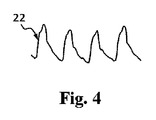
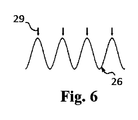
ステップ102において、プロセッサ9は、前記生体構造に対する介入機器3の遠位部分の移動に関する経時的情報を処理する。第1及び第2の実施例に対する代替例の1つにおいて、時間軸に沿った値ストリングが、介入機器3の遠位部分30の移動に関する経時的情報から得られ、前記体外撮像ユニットにより取得された前記介入機器の遠位部分の場所情報から、又は前記体外撮像ユニットに対する前記介入機器の遠位部分に一体化された前記センサの場所情報から導出される。第2及び第3の実施例に対する異なる代替例において、前記生体構造に対する介入機器3の遠位部分30の移動に関する経時的情報は、前記センサにより取得された経時的測定信号から得られ、Mモード、2D、3D及びクロスプレーン視覚化モダリティの少なくとも1つによって前記生体構造の画像をレンダリングするのに使用される。図4及び5に示される、周期的22又は非周期的23のいずれかの経時的値ストリング信号は、リアルタイムで前記画像の少なくとも一部から平均又は中央値を導出することにより得られる。例えば、前記経時的値ストリング信号は、元の画像シーケンスから各画像における(2D、クロスプレーンに対する)全ての画素又はボクセル(3D)の平均値を取ることにより、又は元の画像シーケンスから各画像における全ての画素(2D、クロスプレーン)又はボクセル(3D)の中央値を取ることにより、又は元の画像シーケンスから各画像における全ての画素(2D、クロスプレーン)又はボクセル(3D)から他の単一の統計的パラメータを取ることにより、前記2D、クロスプレーン又は3D超音波画像シーケンスの1つから導出される。前記センサが画像(例えば超音波又はOCT)を提供する他の代替例において、前記経時的値ストリング信号は、所定の方向又は所定の領域における解剖学的構造に対する前記センサの距離から導出される。図6、7において、値ストリング信号26が、典型的に示され、前記値ストリング信号は、時間間隔に対して前記距離の平均によりオフセットされる。例えば、Mモード画像は、特定の時間間隔において単一のラインに沿って取得された情報により構成されるので、前記センサに対する血管壁の距離は、前記Mモード画像から導出されることができる。同様に、2D又は3D画像から、前記センサに対する距離が、関心領域の血管壁に対する様々な角度に対する複数のラインに沿った平均又は中央値として導出されることができる。更に、経時的2D又は3D画像は、複数のMモード画像からなり、そのうち1つ又はいくつかが、前記経時的値ストリング信号を導出するのに選択されることができる。
In
代わりに、前記経時的値ストリング信号は、例えばUS8774906において図5A乃至5C及び図6を参照して第12欄の第3段落から第14欄の最後から3番目の段落の記載によると、心臓の周期的運動中の心臓組織の収縮及び緩和による周期的パターンを有する経時的Mモード画像から導出されるバイナリ信号であってもよい。 Instead, the temporal value string signal is, for example, in US8774906, with reference to FIGS. 5A-5C and 6, according to the description in the third to third paragraphs of columns 12 to 14, of the heart. It may be a binary signal derived from a temporal M-mode image having a periodic pattern due to contraction and relaxation of cardiac tissue during periodic exercise.
前記経時的値ストリング信号は、US8774906に記載されるように超音波Mモード画像から導出されてもよく、又はHuman Molecular Genetics, 2013, Vol. 22, No. 18, pages 3798-3806 (doi:10.1093/hmg/ddt230)内のAirong Li他による記事の3802頁の図3Aに示されるようにOCT Mモード画像から導出されてもよい。前記経時的値ストリング信号は、代わりに、前記Mモード画像がレンダリングされる前に、生又は処理された超音波又はOCT信号から直接的に導出されてもよい。 The temporal value string signal may be derived from an ultrasound M-mode image as described in US8774906, or Human Molecular Genetics, 2013, Vol. 22, No. 18, pages 3798-3806 (doi: 10.1093). It may be derived from OCTM mode images as shown in Figure 3A on page 3802 of the article by Airong Li et al. In / hmg / ddt230). The temporal value string signal may instead be derived directly from the raw or processed ultrasound or OCT signal before the M-mode image is rendered.
ステップ103において、前記プロセッサは、介入機器3の遠位部分30の移動に関する経時的情報が周期的であるか又は非周期的であるかを確認する。一例において、ステップ102からの経時的値ストリング信号22、23が周期的であるか又は非周期的であるかが、デジタルスペクトル解析により確認される。短時間フーリエスペクトルに基づいて、実行中の経時的値ストリング信号は、(時間において)窓関数をかけられ、複素高速フーリエ変換(FFT)結果の絶対値を使用する前記スペクトルの計算が後に続く。この後に、前記短時間フーリエスペクトルから、帯域幅及び中心周波数が各時間において計算される。前記帯域幅が、十分に小さい(固定の閾値より下)場合、前記信号が周期的であるという決定が行われ、そうでなければ前記信号は非周期的である。前記信号が周期的であると確認される場合、このサイクルの周期は、前記中心周波数の逆数から計算される。前記プロセッサのより少ない計算パワーを要求するので、経時的値ストリング信号22、23の周期性を確認する方が速いが、ステップ101に開示された3つの実施例のいずれかの代替例において、介入機器3の遠位部分30の移動に関する経時的情報の周期性は、それぞれの実施例に対して受信された経時的測定信号から直接的に確認されることができる。第1及び第2の実施例において、前記体外撮像ユニットに対する前記体外撮像ユニットにより又は前記介入機器の遠位部分内に一体化された前記センサにより取得された前記介入機器の遠位部分の場所情報は、前記場所情報が2D空間に関するか又は3D空間に関するかにかかわらず、周期性を確認するのに直接的に使用されてもよい。第2及び第3の実施例に関する他の代替例において、前記センサに対する前記解剖学的構造の距離は、それぞれ2D又は3D画像から導出され、それぞれ2D又は3D空間において前記解剖学的構造の座標又は前記センサに対する前記解剖学的構造の大きさ及び方向により規定されるベクトルを表す2D又は3Dマトリックスであってもよい。
In
図8において22で示されるように、介入機器3の遠位部分30の移動に関する経時的情報が周期的であることが確認される場合、前記プロセッサは、ステップ104において周期的に動く生体構造41の経時的情報のゲーティング24をトリガする。換言すると、周期性がステップ103において確認される場合、前記方法は、ゲーティングステップ104に進む。図9において、オプションとしてなくてもよいステップを有するゲーティングステップ104が、概略的に示される。ステップ107において、前記オプションは、前記ユーザインタフェースを介して医師又は補助人により調整されることができる、前記システムの所定の設定に依存して、2つの可能性に分岐する。ステップ107において、前記ゲーティングが、直接的に介入機器3の遠位部分30の移動に関する経時的情報に基づくか、又はステップ102において導出された経時的値ストリング信号22に基づくべきであるという選択肢が検出される場合、ステップ108において、前記ゲーティングは、その特定の信号に基づいて実行される。他方で、ステップ107において、前記ゲーティングが、介入機器3の遠位部分30の移動に関する経時的情報とは異なる信号に基づくべきであるという選択肢が検出される場合、ゲーティングに対する前記信号は、ステップ109においてユーザにより選択されることができる。ゲーティング信号は、電気的信号測定ユニット8、例えば心電計により提供される経時的体外心電図信号27(図10、11)、又は前記介入機器の遠位部分上に一体化された前記少なくとも1つのセンサにより提供される経時的体内電位図信号の1つであってもよい。
As shown by 22 in FIG. 8, if it is confirmed that the temporal information regarding the movement of the
ゲーティングに使用される周期的信号の位相は、前記システムの設定においてあらかじめ決定されてもよく、及び/又は前記ユーザインタフェースを介してユーザにより調整されてもよい。ステップ110において、周期Tの位相が前記ユーザにより選択28されるべきであることが決定される場合(図7、11)、ステップ111において、前記ユーザインタフェースは、前記ユーザから選択された位相を導入又は確認するように要求する。他の例において、前記プロセッサは、ステップ112において自動ピーク検出(図6、10)を使用する、又は自動的に検出されたピーク29から遅延される特定の所定の位相を使用する。一度周期Tの位相が、前記ユーザにより選択されるか、又は前記プロセッサにより自動的に検出されるかのいずれかであると、周期的に動く生体構造41の経時的情報のゲーティング24が、完了され、結果として周期的に動く生体構造41のゲーティングされた経時的情報25を生じる(図8)。周期的に動く生体構造41のゲーティングされた経時的情報25は、ゲーティングに使用される連続した周期の同じ位相に対応する画像フレームのシーケンス、又はゲーティングに使用される連続した周期の同じ位相に対応する周期的に動く生体構造41の他の経時的測定データであることができる。
The phase of the periodic signal used for gating may be predetermined in the settings of the system and / or may be adjusted by the user via the user interface. In
ステップ105において、前記プロセッサは、介入機器3の遠位部分30の移動に関する経時的情報が周期的であると確認される場合に、周期的に動く生体構造41のゲーティングされた経時的情報を出力し、ステップ106において、介入機器3の遠位部分30の移動に関する経時的情報が非周期的であると確認される場合に、受信されたままの周期的に動く生体構造41の経時的情報を出力する。結果として、第1乃至第3の実施例又はこれらの他の代替的な変形例のいずれかにおいて、前記プロセッサは、前記周期的に動く生体構造のゲーティングされた経時的情報、又は前記システムの動作中の任意の時点に受信された前記周期的に動く生体構造の経時的情報を出力する。前記周期的に動く生体構造のゲーティングされた経時的情報は、超音波、X線、OCT、MR撮像モダリティのいずれかのMモード、2D、クロスプレーン、3D視覚化モダリティの1つであってもよい。
In
臨床的な例において、前記生体構造は、心臓である。医師又は補助人が、前記目標場所を見つけるようにリアルタイムフィードバックを必要とし、前記介入機器の遠位部分が不所望な経路を取る場合に迅速に反応し、軌道を修正しなければならないという事実のため、心臓の心室又は心臓の血管内の目標場所までの介入機器のナビゲーションに対して、周期的に動く心臓の経時的測定信号が受信されたままで出力されることが好ましい。ナビゲーション中に、前記介入機器の遠位部分は、関心のある前記目標場所に対して前進又は後退される。他方で、前記目標場所が前記介入機器の遠位部分により到達される場合、前記医師又は補助人の関心は、安定した測定又は画像を取得することである。前記測定は、心臓の周期的運動により影響されるので、前記経時的測定信号のリアルタイム出力は、前記測定信号の速い周期的変化を引き起こし、これは、診断測定を取得する又は治療処置を実行するのに適した状況であるかどうか決定する医師又は補助人を混乱させるかもしれない。前記実施例のいずれかによると、周期的に動く心臓の経時的情報は、自動的にゲーティングされ、前記装置は、カテーテルが前記目標場所に対して前進又は後退されない場合にゲーティングされた情報のみを出力する。前記機器の遠位部分が、前記目標場所から移動される場合、前記装置は、受信されたままで周期的に動く心臓の経時的情報を出力するように自動的に切り替わり、これにより周期的に動く心臓のゲーティングされた経時的情報を出力することを自動的に終了する。典型的な視覚化は、図12に示され、心室41の3D超音波画像が、前記介入機器の遠位部分30の存在下で示されている。
In a clinical example, the biological structure is the heart. The fact that the physician or assistant needs real-time feedback to find the target location and must react quickly and correct the trajectory if the distal portion of the intervention device takes an undesired path. Therefore, it is preferable that the temporal measurement signal of the periodically moving heart is output as it is received for the navigation of the intervention device to the target location in the ventricle of the heart or the blood vessel of the heart. During navigation, the distal portion of the intervention device is advanced or retracted relative to the target location of interest. On the other hand, if the target location is reached by the distal portion of the intervention device, the interest of the physician or assistant is to obtain a stable measurement or image. Since the measurement is influenced by the periodic movement of the heart, the real-time output of the measurement signal over time causes a rapid periodic change of the measurement signal, which obtains a diagnostic measurement or performs a therapeutic procedure. It may confuse the doctor or assistant who decides if the situation is suitable for. According to any of the above embodiments, the temporal information of the cyclically moving heart is automatically gated, and the device is gated when the catheter is not advanced or retracted with respect to the target location. Output only. When the distal portion of the device is moved from the target location, the device automatically switches to output temporal information of the periodically moving heart as it is received, thereby moving periodically. Automatically terminates the output of the heart's gated temporal information. A typical visualization is shown in FIG. 12, where a 3D ultrasound image of the
前記画像は、空間的及び/又は時間的フィルタ処理を適用し、グレイレベルを調整することにより更に後処理されてもよい。前記後処理は、追加の計算パワーを要求してもよく、これは、撮像のリアルタイム実行に影響を与えてもよい。 The image may be further post-processed by applying spatial and / or temporal filtering and adjusting the gray level. The post-processing may require additional computational power, which may affect the real-time execution of imaging.
第2の実施例の他の代替例において、前記少なくとも1つのセンサ、例えば図2のセンサ31は、体外撮像ユニット6により提供される周期的に動く生体構造41の経時的情報より高い解像度及び小さい被写界深度を持つ周期的に動く生体構造41の体内経時的情報を提供するように更に構成される。特定の例において、前記生体構造は、心臓であり、心臓の体内経時的情報は、20乃至45MHzの間隔内の周波数において超音波トランスデューサ31により取得された超音波情報であり、心臓の体外経時的情報は、1乃至10MHzの間隔内の周波数において体外超音波プローブにより取得された超音波情報である。他の代替例において、心臓の血管の体外経時的情報は、超音波情報であり、心臓の血管の体内経時的情報は、OCT情報である。他の代替例において、心臓の体外経時的情報は、X線情報であり、心臓の血管の体内経時的情報は、OCT又は超音波情報である。前記プロセッサは、周期的に動く生体構造41の体外情報及び体内情報を位置合わせするように更に構成される。前記位置合わせは、前記体外撮像ユニットにより、図1に示される前記システムを参照する記載にリストされた他の追跡技術により、又は周期的に動く心臓の体内情報及び体外情報の両方における同一の形態フィーチャの自動セグメンテーション及び識別により、前記介入機器の遠位部分上に一体化された前記センサの追跡に基づいてもよい。代替例において、前記周期的に動く生体構造の体外及び体内情報の位置合わせは、前記ゲーティングステップの前に実行され、前記周期的に動く生体構造の経時的体内情報は、前記周期的に動く生体構造の経時的体外情報と同様にゲーティングされる。前記プロセッサは、周期的に動く生体構造41の体内情報により増強された周期的に動く生体構造41の体外経時的情報をディスプレイ20に出力するように更に構成される。代替例において、前記プロセッサは、体外画像内の前記介入機器の遠位部分上の前記センサの場所に対応する位置において前記体外画像上に重ねられた体内画像を前記ディスプレイ上でレンダリングするように構成される。異なる代替例において、前記プロセッサは、前記周期的に動く生体構造の経時的体外情報の被写界深度を計算し、前記計算された被写界深度による情報が前記体内画像により置き換えられる体外画像を前記ディスプレイ上でレンダリングするように構成される。この代替例は、前記体外及び体内画像の両方が、異なる超音波周波数で取得された超音波情報である場合に特に利益がある。
In another alternative of the second embodiment, the at least one sensor, eg, the
本発明の詳細な説明及び例において、前記周期的に動く生体構造の経時的情報は、前記生体構造の形態情報に関するが、本発明は、前記周期的に動く生体構造の経時的情報が、例えば心臓の血管又は心室において、センサ31及び32の1つにより測定可能である、前記生体構造内の血圧及び血流測定のような、経時的生理学的測定を有する場合に適用可能である。したがって、センサ31、32の少なくとも1つが前記介入機器の遠位部分上に一体化される前記システムのそれぞれの実施例において、ゲーティングされた経時的生理学的測定は、前記ゲーティングされた経時的形態情報に加えて又は代わりに前記ディスプレイに出力されることができる。
In the detailed description and examples of the present invention, the temporal information of the cyclically moving biological structure relates to the morphological information of the biological structure, but in the present invention, the temporal information of the cyclically moving biological structure is, for example, It is applicable when having physiological measurements over time, such as blood pressure and blood flow measurements in the biological structure, which can be measured by one of the
開示された実施例に対する他の変形例は、図面、開示及び添付の請求項の検討から、請求された発明を実施する当業者により理解及び達成されることができる。 Other modifications to the disclosed embodiments can be understood and achieved by those skilled in the art who practice the claimed invention from the drawings, disclosure and review of the accompanying claims.
請求項において、単語「有する」は、他の要素又はステップを除外せず、不定冠詞「a」又は「an」は、複数を除外しない。 In the claims, the word "have" does not exclude other elements or steps, and the indefinite article "a" or "an" does not exclude more than one.
単一のユニット又は機器が、請求項に記載された複数のアイテムの機能を満たしてもよい。特定の方策が相互に異なる従属請求項に記載されるという単なる事実は、これらの方策の組み合わせが有利に使用されることができないことを示さない。 A single unit or device may fulfill the functions of the plurality of items described in the claims. The mere fact that certain measures are described in different dependent claims does not indicate that a combination of these measures cannot be used in an advantageous manner.
装置2を制御するコンピュータ上で実行される場合に前記装置に方法100のステップを実行させるプログラムコード手段を有するコンピュータプログラムが、提供されてもよい。前記コンピュータプログラムは、他のハードウェアと一緒に又は一部として提供される、光記憶媒体又は半導体媒体のような、適切な媒体上に記憶及び/又は分配されてもよいが、インターネット又は他の有線若しくは無線電気通信システムを介するように他の形で分配されてもよい。
A computer program may be provided that has a program code means that causes the device to perform the steps of
請求項内のいかなる参照符号も、範囲を限定するように解釈されるべきではない。 No reference code in the claims should be construed to limit the scope.
Claims (15)
介入機器の遠位部分の移動に関する経時的情報及び前記周期的に動く生体構造の経時的情報を有する経時的測定信号を受信し、
前記介入機器の遠位部分の移動に関する経時的情報が周期的であるか又は非周期的であるかを確認し、
周期性が確認される場合に、前記周期的に動く生体構造の経時的情報をゲーティングし、
前記介入機器の遠位部分の移動に関する経時的情報が非周期的であると確認される場合に、受信されたままで前記周期的に動く生体構造の経時的情報を出力し、
前記介入機器の遠位部分の移動に関する経時的情報が周期的であると確認される場合に、前記周期的に動く生体構造のゲーティングされた経時的情報を出力する、
ように構成されたプロセッサを有する、
装置。 In a device for visualizing measurement information of a cyclically moving biological structure, the device is
Receives a temporal measurement signal with temporal information regarding the movement of the distal portion of the intervention device and temporal information of the cyclically moving biological structure.
Check if the temporal information regarding the movement of the distal portion of the intervention device is periodic or aperiodic.
When periodicity is confirmed, the temporal information of the cyclically moving biological structure is gated, and the information is gated.
When it is confirmed that the temporal information regarding the movement of the distal portion of the intervention device is aperiodic, the temporal information of the cyclically moving biological structure as received is output.
When it is confirmed that the temporal information regarding the movement of the distal portion of the intervention device is periodic, the gated temporal information of the cyclically moving biological structure is output.
Has a processor configured to
Device.
請求項1に記載の装置と、
前記介入機器と、
前記プロセッサにより出力された情報を表示するように構成されたディスプレイと、
を有するシステム。 In a system that visualizes information on cyclically moving biological structures
The device according to claim 1 and
With the intervention device
A display configured to display information output by the processor, and
System with.
前記プロセッサが、
前記周期的に動く生体構造の前記体外経時的情報及び前記体内経時的情報を位置合わせし、
前記周期的に動く生体構造の前記体内経時的情報により増強された前記周期的に動く生体構造の前記体外経時的情報を前記ディスプレイに出力する、
ように更に構成される、
請求項4に記載のシステム。 The at least one sensor provides in-vivo time information of the cyclically moving biological structure having a higher resolution and a smaller depth of field than the extracorporeal time-dependent information of the periodically moving biological structure provided by the extracorporeal imaging unit. Further configured to provide
The processor
Aligning the external time information and the internal time information of the periodically moving anatomy,
The extracorporeal temporal information of the cyclically moving biological structure enhanced by the in- vivo temporal information of the cyclically moving biological structure is output to the display.
Further configured,
The system according to claim 4.
前記装置のプロセッサが、介入機器の遠位部分の移動に関する経時的情報及び前記周期的に動く生体構造の経時的情報を有する経時的測定信号を受信するステップと、
前記プロセッサが、前記介入機器の遠位部分の移動に関する経時的情報が周期的であるか又は非周期的であるかを確認するステップと、
周期性が確認される場合に、前記プロセッサが、前記周期的に動く生体構造の経時的情報をゲーティングするステップと、
前記介入機器の遠位部分の移動に関する経時的情報が非周期的であると確認される場合に、前記プロセッサが、受信されたままで前記周期的に動く生体構造の経時的情報を出力するステップと、
前記介入機器の遠位部分の移動に関する経時的情報が周期的であると確認される場合に、前記プロセッサが、前記周期的に動く生体構造のゲーティングされた経時的情報を出力するステップと、
を有する方法。 In the method of operating the device that visualizes the measurement signal of the cyclically moving biological structure,
A step in which the processor of the device receives a temporal measurement signal having temporal information regarding the movement of the distal portion of the intervention device and temporal information of the cyclically moving biological structure.
Wherein the processor, the steps of temporal information about movement of the distal portion of the interventional device to confirm whether or aperiodic is periodic,
A step if the periodicity is confirmed, the processor, for gating the time information of the periodically moving anatomy,
When it is confirmed that the temporal information regarding the movement of the distal portion of the intervention device is aperiodic, the processor outputs the temporal information of the cyclically moving biological structure as it is received. ,
When it is confirmed that the temporal information regarding the movement of the distal portion of the intervention device is periodic, the processor outputs the gated temporal information of the cyclically moving biological structure.
Method to have.
Applications Claiming Priority (3)
| Application Number | Priority Date | Filing Date | Title |
|---|---|---|---|
| EP18164256.2 | 2018-03-27 | ||
| EP18164256.2A EP3545849A1 (en) | 2018-03-27 | 2018-03-27 | Apparatus, system and method for visualizing a periodically moving anatomy |
| PCT/EP2019/056643 WO2019185379A1 (en) | 2018-03-27 | 2019-03-18 | Apparatus, system and method for visualizing a periodically moving anatomy |
Publications (2)
| Publication Number | Publication Date |
|---|---|
| JP2021510601A JP2021510601A (en) | 2021-04-30 |
| JP6906113B2 true JP6906113B2 (en) | 2021-07-21 |
Family
ID=61827608
Family Applications (1)
| Application Number | Title | Priority Date | Filing Date |
|---|---|---|---|
| JP2020551380A Active JP6906113B2 (en) | 2018-03-27 | 2019-03-18 | Devices, systems and methods for visualizing cyclically moving biological structures |
Country Status (5)
| Country | Link |
|---|---|
| US (1) | US20210007715A1 (en) |
| EP (2) | EP3545849A1 (en) |
| JP (1) | JP6906113B2 (en) |
| CN (1) | CN111918613A (en) |
| WO (1) | WO2019185379A1 (en) |
Families Citing this family (11)
| Publication number | Priority date | Publication date | Assignee | Title |
|---|---|---|---|---|
| WO2019045144A1 (en) * | 2017-08-31 | 2019-03-07 | (주)레벨소프트 | Medical image processing apparatus and medical image processing method which are for medical navigation device |
| US11931112B2 (en) | 2019-08-12 | 2024-03-19 | Bard Access Systems, Inc. | Shape-sensing system and methods for medical devices |
| US11525670B2 (en) | 2019-11-25 | 2022-12-13 | Bard Access Systems, Inc. | Shape-sensing systems with filters and methods thereof |
| WO2021108697A1 (en) | 2019-11-25 | 2021-06-03 | Bard Access Systems, Inc. | Optical tip-tracking systems and methods thereof |
| EP4110175A1 (en) | 2020-02-28 | 2023-01-04 | Bard Access Systems, Inc. | Optical connection systems and methods thereof |
| EP4127798A1 (en) | 2020-03-30 | 2023-02-08 | Bard Access Systems, Inc. | Optical and electrical diagnostic systems and methods thereof |
| EP4171423A1 (en) | 2020-06-26 | 2023-05-03 | Bard Access Systems, Inc. | Malposition detection system |
| CN216136534U (en) | 2020-06-29 | 2022-03-29 | 巴德阿克塞斯系统股份有限公司 | Medical device system for placing a medical device into the body of a patient |
| CN216317552U (en) | 2020-07-10 | 2022-04-19 | 巴德阿克塞斯系统股份有限公司 | Medical device system for detecting damage and potential damage to optical fiber technology of medical devices |
| CN216675721U (en) * | 2020-08-03 | 2022-06-07 | 巴德阿克塞斯系统股份有限公司 | Bragg grating optical fiber fluctuation sensing and monitoring system |
| US11899249B2 (en) | 2020-10-13 | 2024-02-13 | Bard Access Systems, Inc. | Disinfecting covers for functional connectors of medical devices and methods thereof |
Family Cites Families (22)
| Publication number | Priority date | Publication date | Assignee | Title |
|---|---|---|---|---|
| US8442618B2 (en) * | 1999-05-18 | 2013-05-14 | Mediguide Ltd. | Method and system for delivering a medical device to a selected position within a lumen |
| US9572519B2 (en) * | 1999-05-18 | 2017-02-21 | Mediguide Ltd. | Method and apparatus for invasive device tracking using organ timing signal generated from MPS sensors |
| US7204798B2 (en) * | 2003-01-24 | 2007-04-17 | Proteus Biomedical, Inc. | Methods and systems for measuring cardiac parameters |
| DE102004011156A1 (en) * | 2004-03-08 | 2005-10-06 | Siemens Ag | Method for endoluminal imaging with movement correction |
| US7918793B2 (en) * | 2005-10-28 | 2011-04-05 | Biosense Webster, Inc. | Synchronization of ultrasound imaging data with electrical mapping |
| KR100961856B1 (en) * | 2007-03-08 | 2010-06-09 | 주식회사 메디슨 | Ultrasound system and method for forming ultrasound image |
| EP2129284A4 (en) * | 2007-03-08 | 2012-11-28 | Sync Rx Ltd | Imaging and tools for use with moving organs |
| US8050523B2 (en) | 2007-04-20 | 2011-11-01 | Koninklijke Philips Electronics N.V. | Optical fiber shape sensing systems |
| US8319770B2 (en) * | 2008-07-11 | 2012-11-27 | General Electric Company | Method and apparatus for automatically adjusting user input left ventricle points |
| US11627904B2 (en) * | 2008-10-23 | 2023-04-18 | Koninklijke Philips N.V. | Cardiac and or respiratory gated image acquisition system and method for virtual anatomy enriched real time 2D imaging in interventional radiofrequency ablation or pace maker replacement procecure |
| US8774906B2 (en) | 2009-05-15 | 2014-07-08 | Koninklijke Philips N.V. | Apparatus, method and computer program for determining a property of a heart |
| BR112012031421A2 (en) * | 2010-06-13 | 2016-11-08 | Angiometrix Corp | method for recovering a nutrient and nutrient recovery system, method for determining information about a vascular body lumen, method for determining information for a vascular body lumen, medical device adapted for determining information about a vascular body lumen, method for providing an elongated medical device for determining information about a vascular body lumen, method for determining an individual's lumen path in a 3d volume, lumen path system, method for determining the axial translation of a medical device within a body lumen vascular, method for obtaining a phase-dependent 3d lumen path for obtaining reference information for diagnostic guidance for in vivo medical processing, method for orienting an endo-lumen instrument in a lumen to a region of interest |
| JP6122096B2 (en) | 2012-03-23 | 2017-04-26 | コーニンクレッカ フィリップス エヌ ヴェKoninklijke Philips N.V. | Imaging system for imaging periodically moving objects |
| EP2827776B1 (en) * | 2012-03-23 | 2016-01-20 | Koninklijke Philips N.V. | Imaging system for imaging a periodically moving object |
| WO2014039589A1 (en) * | 2012-09-05 | 2014-03-13 | Boston Scientific Scimed Inc. | Characterization of tissue by ultrasound echography |
| US20140188440A1 (en) * | 2012-12-31 | 2014-07-03 | Intuitive Surgical Operations, Inc. | Systems And Methods For Interventional Procedure Planning |
| US10448860B2 (en) * | 2013-03-13 | 2019-10-22 | The Johns Hopkins University | System and method for bioelectric localization and navigation of interventional medical devices |
| US20150164605A1 (en) * | 2013-12-13 | 2015-06-18 | General Electric Company | Methods and systems for interventional imaging |
| US10912523B2 (en) * | 2014-03-24 | 2021-02-09 | Intuitive Surgical Operations, Inc. | Systems and methods for anatomic motion compensation |
| EP3181055A1 (en) * | 2015-12-16 | 2017-06-21 | Universitätsklinikum Hamburg-Eppendorf | Ultrasonic device for detecting the heartbeat of a patient |
| US10022101B2 (en) * | 2016-02-29 | 2018-07-17 | General Electric Company | X-ray/intravascular imaging colocation method and system |
| US11406352B2 (en) * | 2016-05-19 | 2022-08-09 | Acist Medical Systems, Inc. | Position sensing in intravascular processes |
-
2018
- 2018-03-27 EP EP18164256.2A patent/EP3545849A1/en not_active Withdrawn
-
2019
- 2019-03-18 EP EP19709975.7A patent/EP3773229A1/en active Pending
- 2019-03-18 CN CN201980022579.2A patent/CN111918613A/en active Pending
- 2019-03-18 WO PCT/EP2019/056643 patent/WO2019185379A1/en unknown
- 2019-03-18 JP JP2020551380A patent/JP6906113B2/en active Active
- 2019-03-18 US US17/041,207 patent/US20210007715A1/en not_active Abandoned
Also Published As
| Publication number | Publication date |
|---|---|
| EP3545849A1 (en) | 2019-10-02 |
| EP3773229A1 (en) | 2021-02-17 |
| JP2021510601A (en) | 2021-04-30 |
| US20210007715A1 (en) | 2021-01-14 |
| CN111918613A (en) | 2020-11-10 |
| WO2019185379A1 (en) | 2019-10-03 |
Similar Documents
| Publication | Publication Date | Title |
|---|---|---|
| JP6906113B2 (en) | Devices, systems and methods for visualizing cyclically moving biological structures | |
| US8126239B2 (en) | Registering 2D and 3D data using 3D ultrasound data | |
| EP1699361B1 (en) | System for guiding a medical instrument in a patient body | |
| RU2667617C2 (en) | System and method of elastographic measurements | |
| US9747689B2 (en) | Image processing system, X-ray diagnostic apparatus, and image processing method | |
| MXPA06004651A (en) | Display of a two-dimensional fan shaped ultrasound field. | |
| MXPA06004653A (en) | Ultrasound imaging catheter with registration of electro-anatomical map and pre-acquired image. | |
| MXPA06004654A (en) | Registration of ultrasound data with pre-acquired image. | |
| JP2005529701A (en) | Computer generated display of imaging pattern of imaging device | |
| KR20080106860A (en) | Cardiac mechanical assessment using ultrasound | |
| WO2010065786A1 (en) | System and method for determining the positioin of the tip of a medical catheter within the body of a patient | |
| MXPA06004656A (en) | Display of catheter tip with beam direction for ultrasound system. | |
| EP2411963A1 (en) | Improvements to medical imaging | |
| US20220240780A1 (en) | System and method for real-time creation of cardiac electro-physiology signals in the heart | |
| JP6489637B2 (en) | In vivo motion tracking device | |
| JP6938469B2 (en) | A device that characterizes blood vessels | |
| JP2020501865A (en) | Navigation platform for medical devices, especially cardiac catheters | |
| US20230338010A1 (en) | Automated control of intraluminal data acquisition and associated devices, systems, and methds | |
| EP3570756B1 (en) | System for imaging and tracking interventional devices | |
| US20220409180A1 (en) | Estimating strain on tissue using 4d ultrasound catheter | |
| WO2024006367A1 (en) | Ultrasound measurement interface systems and methods | |
| CN115919364A (en) | Ultrasound imaging of cardiac anatomy using Doppler analysis |
Legal Events
| Date | Code | Title | Description |
|---|---|---|---|
| A621 | Written request for application examination |
Free format text: JAPANESE INTERMEDIATE CODE: A621 Effective date: 20200923 |
|
| A871 | Explanation of circumstances concerning accelerated examination |
Free format text: JAPANESE INTERMEDIATE CODE: A871 Effective date: 20200923 |
|
| A975 | Report on accelerated examination |
Free format text: JAPANESE INTERMEDIATE CODE: A971005 Effective date: 20210305 |
|
| A131 | Notification of reasons for refusal |
Free format text: JAPANESE INTERMEDIATE CODE: A131 Effective date: 20210311 |
|
| A521 | Written amendment |
Free format text: JAPANESE INTERMEDIATE CODE: A523 Effective date: 20210604 |
|
| TRDD | Decision of grant or rejection written | ||
| A01 | Written decision to grant a patent or to grant a registration (utility model) |
Free format text: JAPANESE INTERMEDIATE CODE: A01 Effective date: 20210622 |
|
| A61 | First payment of annual fees (during grant procedure) |
Free format text: JAPANESE INTERMEDIATE CODE: A61 Effective date: 20210628 |
|
| R150 | Certificate of patent or registration of utility model |
Ref document number: 6906113 Country of ref document: JP Free format text: JAPANESE INTERMEDIATE CODE: R150 |