WO2016139793A1 - Mounting management device - Google Patents
Mounting management device Download PDFInfo
- Publication number
- WO2016139793A1 WO2016139793A1 PCT/JP2015/056471 JP2015056471W WO2016139793A1 WO 2016139793 A1 WO2016139793 A1 WO 2016139793A1 JP 2015056471 W JP2015056471 W JP 2015056471W WO 2016139793 A1 WO2016139793 A1 WO 2016139793A1
- Authority
- WO
- WIPO (PCT)
- Prior art keywords
- production
- jobs
- job
- mounting
- component
- Prior art date
Links
Images


Classifications
-
- H—ELECTRICITY
- H05—ELECTRIC TECHNIQUES NOT OTHERWISE PROVIDED FOR
- H05K—PRINTED CIRCUITS; CASINGS OR CONSTRUCTIONAL DETAILS OF ELECTRIC APPARATUS; MANUFACTURE OF ASSEMBLAGES OF ELECTRICAL COMPONENTS
- H05K13/00—Apparatus or processes specially adapted for manufacturing or adjusting assemblages of electric components
- H05K13/04—Mounting of components, e.g. of leadless components
-
- G—PHYSICS
- G06—COMPUTING; CALCULATING OR COUNTING
- G06Q—INFORMATION AND COMMUNICATION TECHNOLOGY [ICT] SPECIALLY ADAPTED FOR ADMINISTRATIVE, COMMERCIAL, FINANCIAL, MANAGERIAL OR SUPERVISORY PURPOSES; SYSTEMS OR METHODS SPECIALLY ADAPTED FOR ADMINISTRATIVE, COMMERCIAL, FINANCIAL, MANAGERIAL OR SUPERVISORY PURPOSES, NOT OTHERWISE PROVIDED FOR
- G06Q10/00—Administration; Management
-
- G—PHYSICS
- G06—COMPUTING; CALCULATING OR COUNTING
- G06Q—INFORMATION AND COMMUNICATION TECHNOLOGY [ICT] SPECIALLY ADAPTED FOR ADMINISTRATIVE, COMMERCIAL, FINANCIAL, MANAGERIAL OR SUPERVISORY PURPOSES; SYSTEMS OR METHODS SPECIALLY ADAPTED FOR ADMINISTRATIVE, COMMERCIAL, FINANCIAL, MANAGERIAL OR SUPERVISORY PURPOSES, NOT OTHERWISE PROVIDED FOR
- G06Q50/00—Systems or methods specially adapted for specific business sectors, e.g. utilities or tourism
- G06Q50/04—Manufacturing
-
- H—ELECTRICITY
- H05—ELECTRIC TECHNIQUES NOT OTHERWISE PROVIDED FOR
- H05K—PRINTED CIRCUITS; CASINGS OR CONSTRUCTIONAL DETAILS OF ELECTRIC APPARATUS; MANUFACTURE OF ASSEMBLAGES OF ELECTRICAL COMPONENTS
- H05K13/00—Apparatus or processes specially adapted for manufacturing or adjusting assemblages of electric components
- H05K13/0015—Orientation; Alignment; Positioning
-
- H—ELECTRICITY
- H05—ELECTRIC TECHNIQUES NOT OTHERWISE PROVIDED FOR
- H05K—PRINTED CIRCUITS; CASINGS OR CONSTRUCTIONAL DETAILS OF ELECTRIC APPARATUS; MANUFACTURE OF ASSEMBLAGES OF ELECTRICAL COMPONENTS
- H05K13/00—Apparatus or processes specially adapted for manufacturing or adjusting assemblages of electric components
- H05K13/02—Feeding of components
-
- H—ELECTRICITY
- H05—ELECTRIC TECHNIQUES NOT OTHERWISE PROVIDED FOR
- H05K—PRINTED CIRCUITS; CASINGS OR CONSTRUCTIONAL DETAILS OF ELECTRIC APPARATUS; MANUFACTURE OF ASSEMBLAGES OF ELECTRICAL COMPONENTS
- H05K13/00—Apparatus or processes specially adapted for manufacturing or adjusting assemblages of electric components
- H05K13/04—Mounting of components, e.g. of leadless components
- H05K13/0417—Feeding with belts or tapes
-
- H—ELECTRICITY
- H05—ELECTRIC TECHNIQUES NOT OTHERWISE PROVIDED FOR
- H05K—PRINTED CIRCUITS; CASINGS OR CONSTRUCTIONAL DETAILS OF ELECTRIC APPARATUS; MANUFACTURE OF ASSEMBLAGES OF ELECTRICAL COMPONENTS
- H05K13/00—Apparatus or processes specially adapted for manufacturing or adjusting assemblages of electric components
- H05K13/08—Monitoring manufacture of assemblages
- H05K13/085—Production planning, e.g. of allocation of products to machines, of mounting sequences at machine or facility level
- H05K13/0853—Determination of transport trajectories inside mounting machines
-
- H—ELECTRICITY
- H05—ELECTRIC TECHNIQUES NOT OTHERWISE PROVIDED FOR
- H05K—PRINTED CIRCUITS; CASINGS OR CONSTRUCTIONAL DETAILS OF ELECTRIC APPARATUS; MANUFACTURE OF ASSEMBLAGES OF ELECTRICAL COMPONENTS
- H05K13/00—Apparatus or processes specially adapted for manufacturing or adjusting assemblages of electric components
- H05K13/08—Monitoring manufacture of assemblages
- H05K13/086—Supply management, e.g. supply of components or of substrates
-
- H—ELECTRICITY
- H05—ELECTRIC TECHNIQUES NOT OTHERWISE PROVIDED FOR
- H05K—PRINTED CIRCUITS; CASINGS OR CONSTRUCTIONAL DETAILS OF ELECTRIC APPARATUS; MANUFACTURE OF ASSEMBLAGES OF ELECTRICAL COMPONENTS
- H05K13/00—Apparatus or processes specially adapted for manufacturing or adjusting assemblages of electric components
- H05K13/08—Monitoring manufacture of assemblages
- H05K13/0882—Control systems for mounting machines or assembly lines, e.g. centralized control, remote links, programming of apparatus and processes as such
Definitions
- the present invention relates to a mounting management apparatus.
- a component mounting apparatus that picks up a component from a component supply tape sent to a component supply position by a nozzle of a head and mounts the component on a substrate.
- the component supply tape is supplied to the component supply position by the tape feeder.
- the tape feeder is held in a state of being inserted into a slot on the pallet of the component mounting apparatus.
- a plurality of such component mounting apparatuses are arranged side by side to construct a mounting line, and various boards for high-mix low-volume production are produced.
- it has been proposed to use a grouping method For example, Patent Document 1 describes that grouping is performed by combining large and small orders (production jobs) of the number of lots (production number).
- Patent Document 1 describes a grouping that combines orders with large and small lot numbers, in that case, how is the time required to produce one substrate for an order with a large lot number? It was not considered. If the time required to produce one substrate for an order with a large number of lots becomes a little longer, the total time required for processing the orders in the group will become significantly longer as a result of the larger number of lots. Therefore, the problem that production efficiency becomes low arises.
- the present invention has been made to solve the above-described problems, and has as its main object to shorten the total time required for processing production jobs within a group.
- the mounting management apparatus of the present invention A mounting management device that manages a mounting line including at least one component mounting device that picks up a component from a component supply tape sequentially sent out by a tape feeder held on a pallet by a nozzle and mounts it on a substrate, Storage means for storing a plurality of production jobs including information on which types of components are mounted on the board and information on production volumes; Group number setting means for setting the number of groups to N (N is a natural number); From the largest production volume to the Nth largest production volume of the plurality of production jobs are set as N group reference jobs, and the production time required for processing the reference jobs is shortened based on the reference jobs.
- the placement position of the tape feeder on the pallet is determined, and the remaining production jobs obtained by removing the reference job from the plurality of production jobs are assigned to any of the N groups, and the remaining production jobs are performed.
- Feeder position determining means for determining an arrangement position of the tape feeder on the pallet based on a job; It is equipped with.
- the arrangement position of the tape feeder on the pallet is determined so that the production time of the production job with the largest production volume in the group is shortened. Since the production time of a production job having a large production volume accounts for a high percentage of the total production time required for processing the production job in the group, the total production time can be shortened as a result.
- the feeder position determination unit may perform either the process of determining the placement position of the tape feeder based on the reference job or the process of grouping the remaining production jobs first or in parallel. .
- the setting means sets the number of groups to N based on the total number of component types included in the plurality of production jobs and the total number of slots holding the tape feeder included in the mounting line. It may be set individually. In this way, the number of groups can be automatically set. However, the setting means may set the value input by the operator using the input device as the number of groups.
- the feeder position determination unit may perform grouping so that the remaining production jobs have the same group with priority given to parts having a high degree of commonality with the reference job. .
- the feeder position determination unit may perform grouping so that the remaining production jobs have the same group with priority given to parts having a high degree of commonality with the reference job. .
- the parts with a high degree of commonality in the parts are in the same group, the number of tape feeders can be reduced, the number of tape feeder placement operations can be reduced, and the production preparation time can be reduced.
- the feeder position determination may be performed again by incrementing the number of N by 1 when all of the plurality of production jobs cannot be finally grouped. In this way, when the set number of groups is insufficient, the number of groups can be automatically increased and the grouping can be terminated.
- the production volume of the board after the component mounting may be used as the production volume. Since the production time increases as the number of produced sheets increases, the total production time can be shortened by adopting the produced number as a production volume. Alternatively, a production time required for processing the production job may be used as the production volume. If the production time is adopted as the production volume, the total production time can be shortened.
- the production time can be obtained as a value obtained by multiplying the production time per substrate, for example, by obtaining the production time per substrate.
- FIG. 1 is a schematic explanatory diagram of a component mounting system 1.
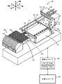
- FIG. The perspective view of the component mounting apparatus 10.
- FIG. The perspective view of the device pallet 42.
- FIG. FIG. 3 is a schematic explanatory diagram of a reel unit 40.
- FIG. The flowchart of a setup routine. Explanatory drawing showing the mode of grouping of the production job of this embodiment. Explanatory drawing showing the mode of grouping of the production job of a comparison form.
- FIG. 1 is a schematic explanatory diagram of the component mounting system 1
- FIG. 2 is a perspective view of the component mounting apparatus 10
- FIG. 3 is a perspective view of a device pallet 42
- FIG. 4 is a schematic explanatory diagram of a reel unit 40
- FIG. It is a perspective view.
- the left-right direction (X-axis), the front-rear direction (Y-axis), and the up-down direction (Z-axis) are as shown in FIGS.
- the component mounting system 1 includes a plurality of component mounting apparatuses 10 that form a mounting line 11, a reel unit 40 that supplies components to each component mounting apparatus 10, and a management that manages the production of the substrate S. And a computer 80.
- each component mounting apparatus 10 sequentially mounts components supplied from each reel unit 40 on the substrate S sent from the upstream side, and sends them out downstream after the mounting is completed.
- the component mounting apparatus 10 includes a board transfer device 12, a head 18, a nozzle 28, a parts camera 36, and a mounting controller 38 that executes various controls.
- the substrate transport device 12 transports the substrate S from the left to the right by the conveyor belts 16 and 16 (only one is shown in FIG. 2) attached to the pair of left and right support plates 14 and 14, respectively.
- the head 18 is movable on the XY plane. Specifically, the head 18 moves in the left-right direction as the X-axis slider 20 moves in the left-right direction along the guide rails 22, 22, and the Y-axis slider 24 moves along the guide rails 26, 26. It moves in the front-rear direction as it moves in the front-rear direction.
- the nozzle 28 uses pressure to adsorb components to the nozzle tip or release components adsorbed to the nozzle tip.
- a pressure adjusting device (not shown) is connected to the nozzle 28.
- the height of the nozzle 28 is adjusted by a Z-axis motor 30 built in the head 18 and a ball screw 32 extending along the Z-axis.
- the parts camera 36 is installed between the reel unit 40 and the substrate transport apparatus 12 so that the imaging direction is upward at the approximate center of the length in the left-right direction.
- the parts camera 36 images a part adsorbed by the nozzle 28 passing above, and outputs an image obtained by the imaging to the mounting controller 38.
- the mounting controller 38 is configured as a microprocessor centered on a CPU, and includes a ROM that stores processing programs, an HDD that stores various data, a RAM used as a work area, and the like. These are electrically connected via a bus (not shown).
- the mounting controller 38 is connected to the feeder controller 58 of the tape feeder 50 (hereinafter referred to as “feeder 50”) and the management computer 80 so as to be capable of bidirectional communication. Further, the mounting controller 38 is connected so as to be able to output a control signal to the substrate transfer device 12, the X-axis slider 20, the Y-axis slider 24, the Z-axis motor 30, the pressure adjustment device (not shown) of the nozzle 28, and the like. In addition, an image can be received from the parts camera 36.
- the reel unit 40 includes a device pallet 42, a feeder 50, and a reel 60, and is detachably attached to the component mounting apparatus 10.
- the device pallet 42 includes a pallet main body 43 on a flat plate and a standing wall 45 provided at the rear end of the pallet main body 43.
- a plurality of slots 44 formed as grooves extending in the front-rear direction are arranged in the pallet body 43 in the left-right direction.
- a plurality of pallet side connectors 46 are juxtaposed in the left-right direction corresponding to each slot 44 on the front surface of the standing wall 45.
- the feeder 50 is held on the device pallet 42 while being inserted into the slot 44.
- the feeder controller 58 built in the feeder 50 is capable of bidirectional communication with the mounting controller 38.
- the feeder 50 has a sprocket 54 that is rotationally driven by a feeder motor 56.
- the reel 60 is rotatably attached to the front portion of the feeder 50.
- a tape 62 is wound around the reel 60.
- the tape 62 is fed backward by a sprocket 54 built in the feeder 50.
- a plurality of recesses 64 are formed in the tape 62 so as to be aligned along the longitudinal direction of the tape 62.
- Each recess 64 accommodates a component P. These components P are protected by a film 65 that covers the surface of the tape 62.
- the feeder 50 has a component suction position (a position indicated by a white arrow in FIG. 4).
- the component suction position is a position determined by design in which the nozzle 28 sucks the component P.
- the component P that has reached the component suction position is mounted at a predetermined position on the substrate S by the nozzle 28, the component P is not accommodated in the concave portion 64 behind the component suction position.
- the component P is configured such that when the component P reaches the component suction position, the film 65 covering the surface is peeled off. Further, the tape 62 is cut at a position behind the recessed portion 64 that is empty, and the cut portion is discarded.
- the management computer 80 is a microprocessor centered on a CPU 81, and includes a ROM 82 that stores a processing program, an HDD 83 that stores a board production program, and a RAM 84 that is used as a work area. These are electrically connected via a bus (not shown).
- An input signal is input to the management computer 80 from an input device 85 such as a mouse or a keyboard, and an image signal to the display 86 is output from the management computer 80.
- the management computer 80 is connected to the mounting controller 38 of each component mounting apparatus 10 constituting the mounting line 11 so as to be capable of bidirectional communication.
- a production job is stored in the HDD 83 of the management computer 80. Therefore, the HDD 83 corresponds to the storage unit of the present invention.
- the “production job” includes component-related information on what kind of components are mounted on the board in what order, and information on the number of produced sheets on how many boards S so mounted are produced. Hereinafter, it is simply referred to as “job”.
- the mounting controller 38 of the component mounting apparatus 10 mounts components on the board S based on the job.
- the mounting controller 38 carries in the substrate S from the upstream side.
- the mounting controller 38 causes the nozzle 28 of the head 18 to attract the component supplied from the feeder 50 of the reel unit 40.
- the mounting controller 38 controls the X-axis slider 20 and the Y-axis slider 24 to move the nozzle 28 directly above the component suction position of a desired component.
- the mounting controller 38 controls the Z-axis motor 30 and a pressure adjusting device (not shown) of the nozzle 28 to lower the nozzle 28 and supply negative pressure to the nozzle 28. Thereby, a desired part is adsorbed to the tip of the nozzle 28.
- the mounting controller 38 raises the nozzle 28, controls the X-axis slider 20 and the Y-axis slider 24, and moves the nozzle 28, which has attracted components to the tip, above a predetermined position on the substrate S.
- the nozzle 28 that has picked up the component passes over the part camera 36 while moving, and is imaged by the part camera 36.
- the mounting controller 38 determines whether or not a component is attracted to the nozzle 28 based on an image captured by the parts camera 36, and determines the shape, size, suction position, and the like of the component.
- the mounting controller 38 controls the lowering of the nozzle 28 so that atmospheric pressure is supplied to the nozzle 28.
- the parts adsorbed by the nozzle 28 are separated and mounted at a predetermined position on the substrate S.
- Other components to be mounted on the substrate S are similarly mounted on the substrate S, and when the mounting of all the components is completed, the substrate S is sent to the downstream side.
- the mounting line 11 when the component mounting on the substrate S is completed by the upstream component mounting apparatus 10, the substrate S is sent to the downstream component mounting apparatus 10, and the component mounting apparatus 10 mounts the component S on the substrate S. Is done.
- the substrate S that has passed through all the component mounting apparatuses 10 from the uppermost stream to the lowermost stream of the mounting line 11 is the one in which the mounting of all the predetermined components has been completed.
- the nozzle 28 adsorbs the components supplied from the feeder 50 and then passes over the parts camera 36 before moving toward the substrate S. Considering this, the nozzle moving distance becomes shorter as the feeder 50 is closer to the parts camera 36. Further, the shorter the nozzle movement distance, the shorter the nozzle movement time. Therefore, the closer to the parts camera 36 among the feeders 50 arranged in the slot 44 (the closer to the center of the left and right length of the component mounting apparatus 10), the shorter the time required to mount one component.
- the number of jobs A produced is much larger than that of job B. In that case, two arrangement procedures are possible.
- One is a procedure in which a plurality of feeders 50 used for the job B are arranged in the slot 44 near the parts camera 36, and then a plurality of feeders 50 used for the job A are arranged in the remaining slot 44 (first). 1 procedure).
- the other is a procedure in which a plurality of feeders 50 used for job A are arranged in the slot 44 near the parts camera 36, and then a plurality of feeders 50 used for job B are arranged in the remaining slot 44 ( Second procedure).
- the production time per substrate for job B is shorter in the first procedure than in the second procedure, and the production time per substrate in job A is the first procedure in the second procedure. Shorter. However, since the production number of job A is much larger than that of job B, it is advantageous to select the second procedure in consideration of the entire production time.
- job A for mounting k types (k is an integer of 2 or more) on the substrate S job B for mounting m types (m is an integer of 2 or more) on the substrate S, and n types (n).
- job C for mounting a component of 2) is mounted on the substrate S is processed.
- device pallets 42 referred to as one set of device pallets 42 for convenience
- one set Jobs A to C can be processed only by setting up various types of feeders 50 once in the device pallet 42.
- (k + m + n) types of feeders 50 cannot be mounted even if one set of device pallets 42 is used, it is necessary to switch the setup in the middle. This operation is called “setup change”. For example, k types of feeders 50 are mounted on one set of device pallets 42, m types of feeders 50 are mounted on one set of device pallets 42, and n types of feeders 50 are mounted on one set of device pallets 42. Can be installed. In that case, first, k types of feeders 50 are set up in one set of device pallets 42 to process job A, and then m types of feeders 50 are set up again in one set of device pallets 42 to process job B.
- the management computer 80 determines how to arrange the feeders 50 necessary for a plurality of jobs in which slot 44 of the device pallet 42 of all the component mounting apparatuses 10 constituting the mounting line 11. The procedure for this will be described below with reference to the flowchart of the setup routine of FIG. Also refer to FIG. 7 as appropriate.
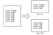
- FIG. 7 is an explanatory diagram showing a state of grouping production jobs.
- the CPU 81 of the management computer 80 starts the setup routine.
- the CPU 81 first reads all jobs to be processed this time from the HDD 83 (step S110).
- jobs 1 to 7 shown on the left side of FIG. 7 are read.
- Each job includes component-related information regarding what kind of components are mounted on the substrate in what order, and information on the number of productions regarding how many substrates S are mounted in that manner.
- FIG. 7 shows only the number of products produced.
- the CPU 81 of the management computer 80 sets the number of groups (step S120).
- a group refers to a job group set up in the device pallet 42 of the same set.
- the CPU 81 sets the number of groups to a number predicted by calculation. For example, the CPU 81 converts an integer value obtained by dividing the total number of component types included in all read jobs by the total number of slots 44 included in one set of device palettes 42 to the number of groups. Set. In the following, for convenience of explanation, it is assumed that the number of groups is set to N (N is a natural number, 2 in the example of FIG. 7).
- the CPU 81 of the management computer 80 sets a reference job for each group (step S130).
- the CPU 81 sets all the read jobs from the largest to the Nth largest to the reference jobs of the first group, the second group,..., The Nth group. Set.
- a job 1 with a production number of 1000 sheets is set as a reference job for the group 1
- a job 2 with a production number of 500 sheets is set as a reference job for the group 2.
- the CPU 81 of the management computer 80 optimizes each reference job (step S140).
- the CPU 81 sequentially determines the arrangement positions of the plurality of types of feeders 50 used for each reference job.
- the feeders in one set of device pallets 42 are set so that the production time of the reference job is as short as possible. 50 arrangement positions are determined.
- the CPU 81 places a plurality of types of feeders 50 used for the reference job in the slot 44 near the parts camera 36. The reason is as already described in the basic concept when determining the arrangement of the feeder 50.
- the parts of the same type that are mounted on the board are arranged closer to the parts camera 36.
- the job 1 is optimized in the group 1 and the job 2 is optimized in the group 2.
- the CPU 81 of the management computer 80 groups the remaining jobs (step S150).
- the CPU 81 performs grouping so that the remaining jobs are grouped in the same group with priority given to parts having a high degree of commonality with the reference job.
- the types of parts are not described.
- jobs 3 and 4 have a high degree of commonality between job 1 and the type of parts. Since job 2 and the types of parts have a high degree of commonality, jobs 3 and 4 are divided into group 1 and jobs 5 to 7 are divided into group 2.
- the CPU 81 of the management computer 80 optimizes jobs other than the reference job among the grouped jobs (step S160).
- the arrangement positions of the plurality of types of feeders 50 used in the reference job of each group have already been determined. Therefore, the CPU 81 determines the arrangement positions of the plurality of types of feeders 50 used in the remaining jobs in the vacant slot 44.
- the feeder 50 of the same type (that is, common) as the feeder 50 used in the reference job is not a target here because the arrangement position has already been determined.
- the CPU 81 optimizes these jobs so that the production times of the component mounting apparatuses 10 constituting the mounting line 11 are as uniform as possible.
- the feeders 50 used for the jobs may be arranged in order from the job with the largest production volume (for example, the number of production) among the remaining jobs.
- the CPU 81 of the management computer 80 outputs a setup result (step S170). For example, as shown in the right side of FIG. 7 as a result of the setup, the CPU 81 provides information that indicates which job is grouped in each of the groups 1, 2,..., N and information that indicates which job is the reference job. The information is displayed on the display 86 or output to each mounting controller 38. After executing step S170, the CPU 81 ends the setup routine.
- the management computer 80 of this embodiment corresponds to the mounting management apparatus of the present invention
- the HDD 83 corresponds to storage means
- the CPU 81 corresponds to group number setting means and feeder position determination means.
- the placement position of the feeder 50 on one set of device pallets 42 is determined so that the production time of the job with the largest production volume (in the present embodiment, the number of produced sheets) is shortened. To do. Since the production time of a job with a large production volume accounts for a high percentage of the total production time required for processing the jobs in the group, the total production time can be shortened as a result.
- FIG. On the other hand, when jobs 1 to 7 similar to those in FIG. 7 are grouped as shown in FIG. 8, the production efficiency is lowered. In other words, in group 1 in FIG.
- management computer 80 sets the number of groups based on the total number of component types included in a plurality of jobs and the total number of slots 44 included in the mounting line 11, it is possible to automatically set the number of groups.
- the management computer 80 performs grouping so that the remaining jobs other than the reference job among all jobs are preferentially grouped in the same group with the parts having a high degree of commonality with the reference job. Therefore, the total number of feeders 50 can be reduced, the number of feeder 50 placement operations can be reduced, and production preparation time can be reduced. Further, when the total number of feeders 50 is reduced, the configuration of the mounting line 11 can be made compact in the case of the same number of groups, and the number of groups can be reduced in the case of the mounting line 11 having the same configuration. If the number of groups is reduced, the number of setup changes is reduced, so the total production time is shortened.
- the number of boards produced after component mounting was used as the production volume.
- the production time increases as the number of produced boards increases, the total production time can be shortened by adopting the production quantity as the production volume. it can.
- the CPU 81 sets the number predicted by calculation to the number of groups when setting the number of groups, but is not particularly limited thereto.
- the relationship between the total number of component types and the number of groups is stored in advance in the HDD 83 as a table, and the CPU 81 reads the number of groups corresponding to the total number of component types this time from the table, and calculates the number of groups. May be set. Even in this way, the number of groups can be automatically set.
- the CPU 81 may set the number of groups input by the operator to the management computer 80 via the input device 85. In this case, the number of groups is manually set, but the operator can set any number of groups.
- step S150 if the number of groups is insufficient after step S150 and finally all the remaining jobs cannot be grouped, the number of groups is increased by 1 (that is, the number of N is incremented by 1).
- the processing after step S130 may be performed again. In this way, if the set number of groups is insufficient, the number of groups is automatically increased, so that all jobs can be grouped.
- the production number is adopted as the production volume, but it is not limited to the production number as long as it is a parameter representing the production volume.
- the production time required for job processing may be adopted as the production volume. If the production time required for job processing is adopted as the production volume, the total production time can be shortened.
- the production time required for job processing can be obtained by, for example, obtaining the production time per substrate by simulation (desktop calculation) and multiplying the production time per substrate by the number of products produced.
- the production time per sheet is obtained by simulation, it may be obtained on the assumption that a plurality of types of parts of the job are arranged in a predetermined part arrangement.
- the production time required for job processing may be obtained by simple calculation.
- the production time required for job processing may be obtained by a simple calculation of multiplying the time required for mounting one component (for example, a value determined by specifications such as catalog values) by the number of job mounting points.
- the CPU 81 of the management computer 80 sets the reference job (S130), the reference job optimization (S140), the remaining job grouping (S150), and the remaining job optimization.
- the processing is performed in the order of conversion (S160), but the order of S140 and S150 may be switched. Even if it does in this way, the effect similar to embodiment mentioned above is acquired.
- the mounting line 11 is configured by a plurality of component mounting apparatuses 10, but the mounting line 11 may be configured by a single component mounting apparatus 10.
- the present invention can be used for management of a component mounting apparatus that picks up a component from a component supply tape sequentially sent out by a tape feeder with a nozzle and mounts it on a substrate.
Abstract
Description
パレットに複数保持されたテープフィーダによって順次送り出される部品供給テープから部品をノズルによりピックアップして基板上に実装する部品実装装置を少なくとも1つ含む実装ラインを管理する実装管理装置であって、
基板にどの種類の部品を実装するかの情報及び生産ボリュームの情報を含む複数の生産ジョブを記憶する記憶手段と、
グループ数をN個(Nは自然数)に設定するグループ数設定手段と、
前記複数の生産ジョブの生産ボリュームの最も大きいものからN番目に大きいものまでをそれぞれN個のグループの基準ジョブとし、前記基準ジョブに基づいて該基準ジョブの処理に要する生産時間が短くなるように前記パレットでの前記テープフィーダの配置位置を決定すると共に、前記複数の生産ジョブから前記基準ジョブを除いた残りの生産ジョブを前記N個のグループのいずれかに割り振るグルーピングを行い、前記残りの生産ジョブに基づいて前記パレットでの前記テープフィーダの配置位置を決定するフィーダ位置決定手段と、
を備えたものである。 The mounting management apparatus of the present invention
A mounting management device that manages a mounting line including at least one component mounting device that picks up a component from a component supply tape sequentially sent out by a tape feeder held on a pallet by a nozzle and mounts it on a substrate,
Storage means for storing a plurality of production jobs including information on which types of components are mounted on the board and information on production volumes;
Group number setting means for setting the number of groups to N (N is a natural number);
From the largest production volume to the Nth largest production volume of the plurality of production jobs are set as N group reference jobs, and the production time required for processing the reference jobs is shortened based on the reference jobs. The placement position of the tape feeder on the pallet is determined, and the remaining production jobs obtained by removing the reference job from the plurality of production jobs are assigned to any of the N groups, and the remaining production jobs are performed. Feeder position determining means for determining an arrangement position of the tape feeder on the pallet based on a job;
It is equipped with.
Claims (6)
- パレットに複数保持されたテープフィーダによって順次送り出される部品供給テープから部品をノズルによりピックアップして基板上に実装する部品実装装置を少なくとも1つ含む実装ラインを管理する実装管理装置であって、
基板にどの種類の部品を実装するかの情報及び生産ボリュームの情報を含む複数の生産ジョブを記憶する記憶手段と、
グループ数をN個(Nは自然数)に設定するグループ数設定手段と、
前記複数の生産ジョブの生産ボリュームの最も大きいものからN番目に大きいものまでをそれぞれN個のグループの基準ジョブとし、前記基準ジョブに基づいて該基準ジョブの処理に要する生産時間が短くなるように前記パレットでの前記テープフィーダの配置位置を決定すると共に、前記複数の生産ジョブから前記基準ジョブを除いた残りの生産ジョブを前記N個のグループのいずれかに割り振るグルーピングを行い、前記残りの生産ジョブに基づいて前記パレットでの前記テープフィーダの配置位置を決定するフィーダ位置決定手段と、
を備えた実装管理装置。 A mounting management device that manages a mounting line including at least one component mounting device that picks up a component from a component supply tape sequentially sent out by a tape feeder held on a pallet by a nozzle and mounts it on a substrate,
Storage means for storing a plurality of production jobs including information on which types of components are mounted on the board and information on production volumes;
Group number setting means for setting the number of groups to N (N is a natural number);
From the largest production volume to the Nth largest production volume of the plurality of production jobs are set as N group reference jobs, and the production time required for processing the reference jobs is shortened based on the reference jobs. The placement position of the tape feeder on the pallet is determined, and the remaining production jobs obtained by removing the reference job from the plurality of production jobs are assigned to any of the N groups, and the remaining production jobs are performed. Feeder position determining means for determining an arrangement position of the tape feeder on the pallet based on a job;
A mounting management device. - 前記設定手段は、前記複数の生産ジョブに含まれる部品種類の総数と前記実装ラインに含まれる前記テープフィーダを保持するスロットの総数とに基づいて前記グループ数をN個に設定する、
請求項1に記載の実装管理装置。 The setting means sets the number of groups to N based on the total number of component types included in the plurality of production jobs and the total number of slots holding the tape feeder included in the mounting line;
The mounting management apparatus according to claim 1. - 前記フィーダ位置決定手段は、前記残りの生産ジョブにつき部品の種類が前記基準ジョブと共通度の高いものを優先して同じグループとなるようにグルーピングを行う、
請求項1又は2に記載の実装管理装置。 The feeder position determining means performs grouping so that the parts of the remaining production jobs have the same group in preference to those having a high degree of commonality with the reference job.
The mounting management apparatus according to claim 1 or 2. - 前記フィーダ位置決定手段は、最終的に前記複数の生産ジョブのすべてをグルーピングできなかった場合には、Nの数を1インクリメントして前記グルーピングを再度行う、
請求項1~3のいずれか1項に記載の実装管理装置。 The feeder position determining means, when all of the plurality of production jobs could not be finally grouped, increments the number of N by 1 and performs the grouping again.
The mounting management apparatus according to any one of claims 1 to 3. - 前記生産ボリュームとして、前記部品実装後の基板の生産枚数を用いる、
請求項1~4のいずれか1項に記載の実装管理装置。 As the production volume, the production number of boards after the component mounting is used,
The mounting management apparatus according to any one of claims 1 to 4. - 前記生産ボリュームとして、前記生産ジョブの処理に要する生産時間を用いる、
請求項1~4のいずれか1項に記載の実装管理装置。 As the production volume, the production time required for processing the production job is used.
The mounting management apparatus according to any one of claims 1 to 4.
Priority Applications (5)
| Application Number | Priority Date | Filing Date | Title |
|---|---|---|---|
| EP15883960.5A EP3267782B1 (en) | 2015-03-05 | 2015-03-05 | Mounting management device |
| PCT/JP2015/056471 WO2016139793A1 (en) | 2015-03-05 | 2015-03-05 | Mounting management device |
| JP2017503285A JP6445132B2 (en) | 2015-03-05 | 2015-03-05 | Mounting management device |
| CN201580077391.XA CN107409491B (en) | 2015-03-05 | 2015-03-05 | Installation management device |
| US15/554,255 US11006558B2 (en) | 2015-03-05 | 2015-03-05 | Mounting management device |
Applications Claiming Priority (1)
| Application Number | Priority Date | Filing Date | Title |
|---|---|---|---|
| PCT/JP2015/056471 WO2016139793A1 (en) | 2015-03-05 | 2015-03-05 | Mounting management device |
Publications (1)
| Publication Number | Publication Date |
|---|---|
| WO2016139793A1 true WO2016139793A1 (en) | 2016-09-09 |
Family
ID=56849226
Family Applications (1)
| Application Number | Title | Priority Date | Filing Date |
|---|---|---|---|
| PCT/JP2015/056471 WO2016139793A1 (en) | 2015-03-05 | 2015-03-05 | Mounting management device |
Country Status (5)
| Country | Link |
|---|---|
| US (1) | US11006558B2 (en) |
| EP (1) | EP3267782B1 (en) |
| JP (1) | JP6445132B2 (en) |
| CN (1) | CN107409491B (en) |
| WO (1) | WO2016139793A1 (en) |
Cited By (6)
| Publication number | Priority date | Publication date | Assignee | Title |
|---|---|---|---|---|
| JP2018037592A (en) * | 2016-09-02 | 2018-03-08 | 富士機械製造株式会社 | Mounting management device |
| JPWO2018092250A1 (en) * | 2016-11-17 | 2019-07-04 | 株式会社Fuji | Setup support device |
| JP2022060328A (en) * | 2016-11-17 | 2022-04-14 | 株式会社Fuji | Setup support device |
| JP2022090072A (en) * | 2019-02-15 | 2022-06-16 | 株式会社Fuji | Component mounting system |
| WO2022130594A1 (en) * | 2020-12-17 | 2022-06-23 | 株式会社Fuji | Management system |
| JP2022121466A (en) * | 2016-11-17 | 2022-08-19 | 株式会社Fuji | Setup support device |
Families Citing this family (5)
| Publication number | Priority date | Publication date | Assignee | Title |
|---|---|---|---|---|
| EP3267780B1 (en) * | 2015-03-06 | 2021-10-27 | FUJI Corporation | Method for optimizing arrangement of part types, and device for optimizing arrangement of part types |
| US20210227731A1 (en) * | 2018-05-28 | 2021-07-22 | Fuji Corporation | Unit exchanging device |
| DE112018007670T5 (en) * | 2018-05-30 | 2021-03-04 | Yamaha Hatsudoki Kabushiki Kaisha | COMPONENT REFILL MANAGEMENT SYSTEM AND COMPONENT ASSEMBLY SYSTEM |
| WO2019229924A1 (en) * | 2018-05-31 | 2019-12-05 | 株式会社Fuji | Component mounting system and method for instructing disposition of component supply unit |
| WO2020202737A1 (en) * | 2019-03-29 | 2020-10-08 | パナソニックIpマネジメント株式会社 | Carrier tape holding device, holder, and carrier tape package body |
Citations (4)
| Publication number | Priority date | Publication date | Assignee | Title |
|---|---|---|---|---|
| JP2003037398A (en) * | 2001-05-17 | 2003-02-07 | Matsushita Electric Ind Co Ltd | Method for optimizing component mounting order, its device and component mounter |
| JP2005159160A (en) * | 2003-11-27 | 2005-06-16 | Yamaha Motor Co Ltd | Surface-mounter and component mounting method thereof |
| JP2009111106A (en) * | 2007-10-30 | 2009-05-21 | Juki Corp | Feeder arrangement optimizing method for component mounting machine |
| WO2014068712A1 (en) * | 2012-10-31 | 2014-05-08 | 富士機械製造株式会社 | Set-up change method, and set-up change device |
Family Cites Families (21)
| Publication number | Priority date | Publication date | Assignee | Title |
|---|---|---|---|---|
| US5155679A (en) * | 1989-12-18 | 1992-10-13 | Hewlett-Packard Company | Set-up optimization for flexible manufacturing systems |
| US5170554A (en) | 1990-09-28 | 1992-12-15 | Hewlett-Packard Company | High mix printed circuit assembly technique |
| US5371940A (en) * | 1991-05-24 | 1994-12-13 | Fujitsu Limited | Pallet arranging system |
| JP3316605B2 (en) | 1994-03-18 | 2002-08-19 | 富士通株式会社 | Integrated manufacturing management system |
| US7127459B2 (en) * | 1996-01-26 | 2006-10-24 | Matsushita Electric Industrial Co., Ltd. | Component electronic catalog |
| JPH09252196A (en) * | 1996-03-14 | 1997-09-22 | Matsushita Electric Ind Co Ltd | Component mounting method |
| JP3728350B2 (en) * | 1996-06-11 | 2005-12-21 | 松下電器産業株式会社 | Component mounting method and component mounting apparatus |
| US6996440B2 (en) * | 2000-08-04 | 2006-02-07 | Matsushita Electric Industrial Co., Ltd. | Method for optimization of an order of component mounting, apparatus using the same, and mounter |
| EP1282350B1 (en) * | 2001-07-20 | 2006-04-26 | Hitachi High-Tech Instruments Co., Ltd. | Electronic component mounting apparatus |
| DE602004013122T2 (en) * | 2003-01-23 | 2009-07-02 | Panasonic Corp., Kadoma | METHOD FOR OPTIMIZING A SEQUENCE OF THE COMPONENT ASSEMBLY, DEVICE THEREFOR AND APPARATUS |
| JP2006171916A (en) * | 2004-12-13 | 2006-06-29 | Matsushita Electric Ind Co Ltd | Production planning method |
| JP2008135699A (en) * | 2006-10-26 | 2008-06-12 | Ricoh Co Ltd | Component mounting apparatus, and control method of same |
| JP5028991B2 (en) * | 2006-12-14 | 2012-09-19 | 富士電機株式会社 | Manufacturing plan creation system and manufacturing plan creation method |
| JP5299380B2 (en) * | 2010-08-17 | 2013-09-25 | パナソニック株式会社 | Component mounting apparatus and component detection method |
| JP5743747B2 (en) * | 2011-06-27 | 2015-07-01 | 富士機械製造株式会社 | Production management apparatus and production management method for component mounting line |
| JP5700694B2 (en) * | 2012-03-13 | 2015-04-15 | 富士通テレコムネットワークス株式会社 | Manufacturing support system |
| US10139813B2 (en) * | 2012-09-12 | 2018-11-27 | Fuji Corporation | Production sequence optimizing method and production sequence optimizing system |
| DE102012221258A1 (en) | 2012-11-21 | 2014-05-22 | Siemens Aktiengesellschaft | Optimization of setup families |
| JP2015082494A (en) * | 2013-10-24 | 2015-04-27 | 株式会社豊田自動織機 | Method of manufacturing electrode and electrode material |
| DE112015006584T5 (en) * | 2015-06-02 | 2018-05-24 | Yamaha Hatsudoki Kabushiki Kaisha | Component feeding apparatus, surface mounting apparatus and method for feeding components |
| WO2018073936A1 (en) * | 2016-10-20 | 2018-04-26 | 富士機械製造株式会社 | Production management device |
-
2015
- 2015-03-05 CN CN201580077391.XA patent/CN107409491B/en active Active
- 2015-03-05 JP JP2017503285A patent/JP6445132B2/en active Active
- 2015-03-05 EP EP15883960.5A patent/EP3267782B1/en active Active
- 2015-03-05 WO PCT/JP2015/056471 patent/WO2016139793A1/en active Application Filing
- 2015-03-05 US US15/554,255 patent/US11006558B2/en active Active
Patent Citations (4)
| Publication number | Priority date | Publication date | Assignee | Title |
|---|---|---|---|---|
| JP2003037398A (en) * | 2001-05-17 | 2003-02-07 | Matsushita Electric Ind Co Ltd | Method for optimizing component mounting order, its device and component mounter |
| JP2005159160A (en) * | 2003-11-27 | 2005-06-16 | Yamaha Motor Co Ltd | Surface-mounter and component mounting method thereof |
| JP2009111106A (en) * | 2007-10-30 | 2009-05-21 | Juki Corp | Feeder arrangement optimizing method for component mounting machine |
| WO2014068712A1 (en) * | 2012-10-31 | 2014-05-08 | 富士機械製造株式会社 | Set-up change method, and set-up change device |
Non-Patent Citations (1)
| Title |
|---|
| See also references of EP3267782A4 * |
Cited By (14)
| Publication number | Priority date | Publication date | Assignee | Title |
|---|---|---|---|---|
| JP2018037592A (en) * | 2016-09-02 | 2018-03-08 | 富士機械製造株式会社 | Mounting management device |
| JP2022060328A (en) * | 2016-11-17 | 2022-04-14 | 株式会社Fuji | Setup support device |
| EP3544400B1 (en) * | 2016-11-17 | 2021-04-21 | Fuji Corporation | Setup support device |
| US10993361B2 (en) | 2016-11-17 | 2021-04-27 | Fuji Corporation | Setup support device |
| JP2021166296A (en) * | 2016-11-17 | 2021-10-14 | 株式会社Fuji | Setup support device |
| JP7025584B2 (en) | 2016-11-17 | 2022-02-24 | 株式会社Fuji | Setup support device |
| JPWO2018092250A1 (en) * | 2016-11-17 | 2019-07-04 | 株式会社Fuji | Setup support device |
| JP7090823B2 (en) | 2016-11-17 | 2022-06-24 | 株式会社Fuji | Setup support device |
| JP2022121466A (en) * | 2016-11-17 | 2022-08-19 | 株式会社Fuji | Setup support device |
| JP7153822B2 (en) | 2016-11-17 | 2022-10-14 | 株式会社Fuji | Setup support device |
| JP2022090072A (en) * | 2019-02-15 | 2022-06-16 | 株式会社Fuji | Component mounting system |
| JP7351964B2 (en) | 2019-02-15 | 2023-09-27 | 株式会社Fuji | Component mounting system |
| WO2022130594A1 (en) * | 2020-12-17 | 2022-06-23 | 株式会社Fuji | Management system |
| JP7385062B2 (en) | 2020-12-17 | 2023-11-21 | 株式会社Fuji | management system |
Also Published As
| Publication number | Publication date |
|---|---|
| EP3267782B1 (en) | 2020-11-18 |
| EP3267782A1 (en) | 2018-01-10 |
| CN107409491B (en) | 2020-04-24 |
| JPWO2016139793A1 (en) | 2017-12-21 |
| US20180084684A1 (en) | 2018-03-22 |
| US11006558B2 (en) | 2021-05-11 |
| EP3267782A4 (en) | 2018-03-21 |
| CN107409491A (en) | 2017-11-28 |
| JP6445132B2 (en) | 2018-12-26 |
Similar Documents
| Publication | Publication Date | Title |
|---|---|---|
| JP6445132B2 (en) | Mounting management device | |
| JP6057359B2 (en) | Production control system for component mounters | |
| JP6355717B2 (en) | DIE MOUNTING SYSTEM AND DIE MOUNTING METHOD | |
| JP2016031959A (en) | Component mount device and component mount method | |
| JPWO2014097389A1 (en) | Component mounter | |
| CN112166660B (en) | Component mounting system and method for instructing placement of component supply unit | |
| WO2019176033A1 (en) | Production job processing method and production job processing device | |
| JP6653640B2 (en) | Setup navigation device, component mounting system, setup navigation method, setup navigation program | |
| JP6752086B2 (en) | Implementation management device | |
| JP2008159855A (en) | Apparatus for mounting electronic component | |
| CN107926152B (en) | Job distribution device | |
| WO2015097865A1 (en) | Component mounting device and component mounting method | |
| JP6526808B2 (en) | Mounting management device | |
| JP6556071B2 (en) | Suction nozzle setup method for surface mounting system and surface mounting system | |
| WO2014118929A1 (en) | Die supply device | |
| WO2016181439A1 (en) | Mounting device and mounting method | |
| WO2016151725A1 (en) | Mounting device and mounting method | |
| JPWO2018179033A1 (en) | Wireless power supply system | |
| CN107926151B (en) | Required precision setting device | |
| JP6604916B2 (en) | Surface mount machine | |
| WO2014038053A1 (en) | Control system and control method for component mounting machine | |
| JP6760790B2 (en) | Surface mounter | |
| WO2022269791A1 (en) | Management device, mounting system, and production method | |
| JP4383633B2 (en) | Component mounting method | |
| CN112602385B (en) | Control program inspection device |
Legal Events
| Date | Code | Title | Description |
|---|---|---|---|
| 121 | Ep: the epo has been informed by wipo that ep was designated in this application |
Ref document number: 15883960 Country of ref document: EP Kind code of ref document: A1 |
|
| ENP | Entry into the national phase |
Ref document number: 2017503285 Country of ref document: JP Kind code of ref document: A |
|
| REEP | Request for entry into the european phase |
Ref document number: 2015883960 Country of ref document: EP |
|
| WWE | Wipo information: entry into national phase |
Ref document number: 15554255 Country of ref document: US |
|
| NENP | Non-entry into the national phase |
Ref country code: DE |