WO2016139738A1 - ステアリングホイール - Google Patents
ステアリングホイール Download PDFInfo
- Publication number
- WO2016139738A1 WO2016139738A1 PCT/JP2015/056126 JP2015056126W WO2016139738A1 WO 2016139738 A1 WO2016139738 A1 WO 2016139738A1 JP 2015056126 W JP2015056126 W JP 2015056126W WO 2016139738 A1 WO2016139738 A1 WO 2016139738A1
- Authority
- WO
- WIPO (PCT)
- Prior art keywords
- steering wheel
- engagement protrusion
- engagement
- circumferential direction
- row
- Prior art date
- Legal status (The legal status is an assumption and is not a legal conclusion. Google has not performed a legal analysis and makes no representation as to the accuracy of the status listed.)
- Ceased
Links
Images







Classifications
-
- B—PERFORMING OPERATIONS; TRANSPORTING
- B62—LAND VEHICLES FOR TRAVELLING OTHERWISE THAN ON RAILS
- B62D—MOTOR VEHICLES; TRAILERS
- B62D1/00—Steering controls, i.e. means for initiating a change of direction of the vehicle
- B62D1/02—Steering controls, i.e. means for initiating a change of direction of the vehicle vehicle-mounted
- B62D1/04—Hand wheels
- B62D1/06—Rims, e.g. with heating means; Rim covers
Definitions
- This disclosure relates to a steering wheel.
- Patent Document 1 discloses a technique for fixing a flexible cover using an insertion piece to a recess of a rim of a steering wheel, as shown in FIGS.
- Patent Document 2 discloses a configuration in which a long groove is formed in the ring portion covering layer, a spring member is accommodated in the long groove, and a small piece member is press-fitted between the side walls of the spring member.
- the inventors of the present application have found the significance of providing a steering wheel annular portion having a novel structure.
- a steering wheel includes a steering wheel annular portion (100), and a steering wheel including an elastic member (300) for fixing a skin material (200) to the steering wheel annular portion (100).
- the first engagement protrusion row (110) includes a plurality of first engagement protrusions (140) arranged at a first interval (W1)
- the second engagement protrusion row (120) includes a plurality of second engagement protrusions (150) arranged at a second interval (W2)
- the first engagement protrusions (140) and the second engagement protrusions (150) are Arranged alternately along the circumferential direction
- the width (W140) of the first engagement protrusion (140) along the circumferential direction is equal to or smaller than the width of the second interval (W2) along the circumferential direction
- the second engagement protrusion (150) along the circumferential direction is equal to or smaller than the width of the first interval (W1) along the circumferential direction.
- the steering wheel annular portion (100) has a main surface (130) extending in the circumferential direction on which the first engagement protrusions (140) and the second engagement protrusions (150) are provided. Prepared, The first engagement protrusion (140) and the second engagement protrusion (150) are respectively recessed in opposite directions in the width direction of the main surface (130) to receive a part of the elastic member (300). It has a receiving recess (160).
- the side edge portion of the skin material (200) includes one or more enormous portions (210) having a thickness that is greater than the thickness of other portions of the skin material (200). .
- the first engagement protrusion row (110) is provided on the front side of the steering wheel (400), and the second engagement protrusion row (120) is provided on the steering wheel (400). Provided on the back side.
- the steering wheel annular portion (100) has a main surface (130) extending in the circumferential direction on which the first engagement protrusions (140) and the second engagement protrusions (150) are provided. Prepared, The major surface (130) is oriented so as to face radially inward of the steering wheel (400).
- a steering wheel annular portion having a novel structure including the first and second engaging protrusion rows.
- FIG. 1 is a schematic front view of a steering wheel according to a first embodiment of the present invention, showing a substantially circular steering wheel annular portion and a T-shaped portion in the steering wheel annular portion, and a central axis AX of the steering wheel annular portion. Is also shown schematically.
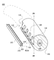
- FIG. 3 is a schematic partial exploded perspective view of a part of the steering wheel annular portion of the steering wheel according to the first embodiment of the present invention, showing a cross section of the steering wheel annular portion and a first engagement protrusion of the steering wheel annular portion.
- the elastic member which should be inserted between a row
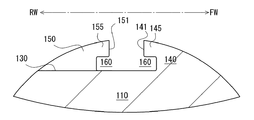
- FIG. 4 is a schematic partial cross-sectional schematic view of the steering wheel annular portion of the steering wheel according to the first embodiment of the present invention, schematically showing a partial cross-section along IV-IV in FIG. 3.
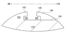
- FIG. 4 is a schematic partial cross-sectional schematic view of the steering wheel annular portion of the steering wheel according to the first embodiment of the present invention, schematically showing a partial cross-section along VV of FIG. 3.
- FIG. 4 is a schematic partial cross-sectional schematic view of the steering wheel annular portion of the steering wheel according to the first embodiment of the present invention, schematically showing a partial cross-section along VV of FIG. 3.
- FIG. 3 is a schematic partial cross-sectional view of the steering wheel according to the first embodiment of the present invention, in which an elastic member is inserted between the first engagement protrusion row and the second engagement protrusion row, and each engagement with the elastic member.
- a state in which the side edge portion of the skin material is held between the protrusion rows and the steering wheel annular portion is covered with the skin material is schematically shown.
- FIG. 3 is a schematic front schematic view of the first engagement protrusion row and the second engagement protrusion row of the steering wheel annular portion of the steering wheel according to the first embodiment of the present invention when viewed from the front; An elastic member is inserted between the second engaging protrusion rows, and a state in which the side edge portion of the skin material is held between the elastic member and each engaging protrusion row is schematically shown.
- 1 is a schematic cross-sectional schematic diagram of a mold used for manufacturing a steering wheel annular portion of a steering wheel according to a first embodiment of the present invention.
- FIG. 10 is a schematic partial cross-sectional schematic view of a steering wheel annular portion of a steering wheel according to a second embodiment of the present invention, schematically showing a partial cross-section along XX in FIG. 9.
- FIG. 10 is a schematic partial cross-sectional schematic view of a steering wheel annular portion of a steering wheel according to a second embodiment of the present invention, schematically showing a partial cross-section along XI-XI in FIG. 9.
- FIG. 10 is a schematic partial cross-sectional schematic view of a steering wheel annular portion of a steering wheel according to a second embodiment of the present invention, schematically showing a partial cross-section along XI-XI in FIG. 9.
- FIG. 10 is a schematic partial cross-sectional schematic view of a steering wheel annular portion of a steering wheel according to a second embodiment of the present invention, schematically showing a partial cross-section along XII-XII in FIG. 9. It is a partial cross section schematic diagram of the skin material which shows the structure of the side edge part of the skin material of the steering wheel which concerns on 3rd Embodiment of this invention. It is a partial section schematic diagram of a steering wheel concerning a 3rd embodiment of the present invention. It is a partial cross section schematic diagram of the skin material which shows the structure of the side edge part of the skin material of the steering wheel which concerns on 4th Embodiment of this invention.
- the circumferential direction is understood according to the shape of the steering wheel / steering wheel annular part.
- the circumferential direction is a direction around the central axis AX of the steering wheel annular portion.
- the radial direction is understood according to the shape of the steering wheel / steering wheel annulus.
- the radially inner side is a direction from the steering wheel annular portion toward the central axis AX of the steering wheel annular portion.
- the radially outer side is a direction toward the opposite side to the radially inner side.
- FIG. 1 is a schematic front view of a steering wheel.
- a substantially circular steering wheel annular portion and a T-shaped portion in the steering wheel annular portion are illustrated, and a central axis AX of the steering wheel annular portion is also schematically shown.
- FIG. 2 is a schematic partial exploded perspective view of a part of the steering wheel annular portion of the steering wheel, showing a cross section of the steering wheel annular portion, a first engagement protrusion row of the steering wheel annular portion, and a second engagement. The elastic member to be inserted between the mating protrusion rows is also illustrated.
- FIG. 1 is a schematic front view of a steering wheel.
- a substantially circular steering wheel annular portion and a T-shaped portion in the steering wheel annular portion are illustrated, and a central axis AX of the steering wheel annular portion is also schematically shown.
- FIG. 2 is a schematic partial exploded perspective view of a part of the steering wheel annular portion of the steering wheel, showing a cross section of the steering wheel annul
- FIG. 3 is a schematic front view of the first engagement protrusion row and the second engagement protrusion row of the steering wheel annular portion of the steering wheel as viewed from the front.
- FIG. 4 is a schematic partial cross-sectional schematic view of a steering wheel annular portion of the steering wheel, schematically showing a partial cross-section along IV-IV in FIG.
- FIG. 5 is a schematic partial cross-sectional schematic view of the steering wheel annular portion of the steering wheel, schematically showing a partial cross-section along VV of FIG.
- FIG. 6 is a schematic partial cross-sectional view of the steering wheel, in which an elastic member is inserted between the first engagement protrusion row and the second engagement protrusion row, and between the elastic member and each engagement protrusion row.
- FIG. 7 is a schematic front view of the first engagement projection row and the second engagement projection row of the steering wheel annular portion of the steering wheel as viewed from the front, and the first engagement projection row and the second engagement projection. An elastic member is inserted between the rows, and a state in which the side edge portion of the skin material is held between the elastic member and each engagement projection row is schematically shown.
- FIG. 8 is a schematic cross-sectional schematic view of a mold used for manufacturing the steering wheel annular portion of the steering wheel.
- the steering wheel 400 has an annular steering wheel annular portion 100 covered with the skin material 200.
- the steering wheel annular portion 100 is a ring having a perfect circular shape around the central axis AX. However, in other embodiments, any other shape such as an elliptical shape may be employed.
- the steering wheel 400 has a T-shaped portion 199 in the ring in addition to the steering wheel annular portion 100.
- the T-shaped portion 199 is provided for reinforcing the steering wheel annular portion 100 or arranging the operation portion.
- the operation unit is an input device for inputting various commands to a vehicle control unit (not shown) to which the steering wheel 400 is attached. In other embodiments, the configuration of the T-shaped part 199 is changed or omitted.
- the skin material 200 that is a covering material of the steering wheel annular portion 100 may be any one of natural leather, artificial leather, woven fabric, knitted fabric, and resin sheet, or any combination thereof.
- FIG. 2 illustrates the steering wheel annular portion 100 and an elastic member 300 for fixing the skin material 200 to the steering wheel annular portion 100.
- the steering wheel annular portion 100 has a substantially perfect circular or elliptical cross section, and has a smooth curved outer surface.
- the steering wheel annular portion 100 includes a core portion 180 and a shell portion 185 that covers the core portion 180.
- a core part 180 is embedded in the shell part 185.
- the core portion 180 is provided to ensure the strength of the steering wheel annular portion 100.
- the core part 180 is made of a high-strength material such as metal or fiber reinforced resin, for example.
- Shell portion 185 is made of a material having lower rigidity than core portion 180.
- the shell portion 185 is made of, for example, a material selected from synthetic rubber, urethane resin, polypropylene, and any combination thereof.
- the elastic member 300 is selected from resins having elasticity, for example, synthetic rubber, urethane resin, polypropylene, and any combination thereof.
- the steering wheel annular portion 100 includes a first engagement protrusion row 110 and a second engagement protrusion row that are provided adjacent to each other to hold the elastic member 300 and the side edge portion 210 of the skin material 200. 120.
- the steering wheel annular portion 100 has a flat surface 130 in a form formed by partial removal of the steering wheel annular portion 100.
- the flat surface 130 is provided with a first engagement projection row 110, each end is provided with a first engagement projection 140 described later, a second engagement projection row 120, and each end is provided with a second engagement projection 150 described later. It is one aspect
- the flat surface 130 does not need to be formed by partially removing the steering wheel annular portion 100, and can be formed by utilizing a mold apparatus as described later.
- the flat surface 130 does not necessarily have to be flat, and may be a non-flat surface in other embodiments.
- the first engagement protrusion row 110 has a plurality of first engagement protrusions 140 arranged with a first interval W1.
- the second engagement protrusion row 120 includes a plurality of second engagement protrusions 150 arranged with a second interval W2.
- each first engaging protrusion and each second engaging protrusion 150 are provided on a common flat surface 130.
- column 110 is provided along the circumferential direction.
- the second engagement protrusion row 120 is provided along the circumferential direction.
- column 120 exist in the aspect parallelly run in the circumferential direction.
- the first engagement protrusion row 110 and the second engagement protrusion row 120 are at different positions.
- Each of the first engagement protrusions 140 of the first engagement protrusion row 110 protrudes radially inward from the flat surface 130.
- Each second engagement protrusion 150 of the second engagement protrusion row 120 protrudes radially inward from the flat surface 130.
- each first engagement protrusion 140 forms the same curved surface as the smooth curved outer surface of the portion of the steering wheel annular portion 100 other than the first engagement protrusion 140.
- the outer surface of each second engagement projection 150 forms the same curved surface as the smooth curved outer surface of the portion of the steering wheel annular portion 100 other than the second engagement projection 150.
- Each first engagement protrusion 140 has a side surface 141 perpendicular to the flat surface 130.
- Each second engagement protrusion 150 has a side surface 151 perpendicular to the flat surface 130.
- the side surface 141 of the first engagement protrusion 140 and the side surface 151 of the second engagement protrusion 150 face each other in opposite directions.
- the side surfaces 141 of the first engagement projections 140 and the side surfaces 151 of the second engagement projections 150 are alternately arranged in the circumferential direction, whereby the first engagement projection row 110 and the second engagement projection row 120 are arranged. Holding of the elastic member 300 and each side edge 210 is achieved.
- the side surface 141 of the first engagement protrusion 140 is expected to be non-flat or non-perpendicular to the flat surface 130.
- the side surface 151 of the second engagement protrusion 150 is non-flat or non-perpendicular to the flat surface 130.
- the flat surface 130 is oriented so as to face the inside in the radial direction.
- the first engagement protrusion row 110 is provided on the front side of the steering wheel 400
- the second engagement protrusion row 120 is provided on the back side of the steering wheel 400.
- the near side of the steering wheel 400 is indicated by an arrow FW
- the far side of the steering wheel 400 is indicated by an arrow RW.
- the steering wheel 400 usually has a front side facing the driver side and a back side opposite to the front side.
- the flat surface 130 may be oriented to face radially outward.
- the first engagement protrusion row 110 is provided on the front side of the steering wheel 400
- the second engagement protrusion row 120 is provided on the back side of the steering wheel 400.
- the first engagement protrusion row 110 is provided on the back side of the steering wheel 400
- the second engagement protrusion row 120 is provided on the front side of the steering wheel 400.
- the flat surface 130 is oriented so as to face the front side or the back side of the steering wheel 400, and the first engagement projection row 110 / second engagement projection row 120 are radially inward / It can be arranged radially outward.
- the first engagement protrusions 140 and the second engagement protrusions 150 are arranged alternately / alternately along the circumferential direction. It can also be understood that the first engagement protrusions 140 and the second engagement protrusions 150 are arranged in a zigzag / zigzag shape in the circumferential direction. Such an arrangement of the engaging protrusions has higher visibility than the long grooves as in Patent Documents 1 and 2, and can contribute to the efficiency of the assembly work. Such an arrangement of the engaging protrusions is also preferable from the viewpoint of manufacturing the steering wheel annular portion 100. When a long groove like patent documents 1 and 2 is provided in steering wheel annular part 100, the composition of a metallic mold device may become complicated.
- the arrangement interval of the first engagement protrusions 140 in the circumferential direction need not be the same as the arrangement interval of the second engagement protrusions 150 in the circumferential direction, and in some embodiments, the first engagement protrusions 140 in the circumferential direction. Is different from the arrangement interval of the second engagement protrusions 150 in the circumferential direction.
- the interval between the first engagement protrusions 140 adjacent along the circumferential direction is the first interval W1
- the second engagement protrusion 150 adjacent along the circumferential direction is the same.
- the interval is the second interval W2.
- the first engagement protrusion 140 has a width W140 along the circumferential direction.
- the second engagement protrusion 150 has a width W150 along the circumferential direction.
- the width W140 of the first engagement protrusion 140 is equal to or less than the second interval W2, and the width W150 of the second engagement protrusion 150 is equal to or less than the first interval W1.
- the width W140 of the first engagement protrusion 140 is equal to the second interval W2, and the width W150 of the second engagement protrusion 150 is equal to the first interval W1.
- the elastic member 300 is inserted between the first engagement protrusion 140 and the second engagement protrusion row 120, whereby one side edge 210 of the skin material 200 having a short width is formed in the first engagement as shown in FIG. It is held between the mating protrusion 140 and the elastic member 300, and the other side edge portion 210 of the short-width skin material 200 is held between the second engagement protrusion row 120 and the elastic member 300. Based on the cooperation between the elastic member 300 and the first engagement protrusion 140 and the cooperation between the elastic member 300 and the second engagement protrusion row 120, the elastic force is generated between the first engagement protrusion row 110 and the second engagement protrusion row 120. The holding of the side edge portions 210 on both sides of the member 300 and the elastic member 300 is ensured.
- the skin material 200 is inserted between the first engagement protrusion 140 and the second engagement protrusion row 120 when the elastic member 300 is inserted between the first engagement protrusion 140 and the second engagement protrusion row 120. Entrained.
- the first engagement protrusion 140 and the second engagement protrusion are arranged in a state where the side edge portions 210 of the skin material 200 are disposed between the first engagement protrusion 140 and the second engagement protrusion row 120.
- the elastic member 300 is inserted between the rows 120. As the elastic member 300 enters between the first engagement protrusion 140 and the second engagement protrusion row 120, the skin material 200 is stretched on the outer surface of the steering wheel annular portion 100, and the skin is applied to the outer surface of the steering wheel annular portion 100.
- the material 200 adheres closely.
- the gap between the first engaging protrusions 140 adjacent in the circumferential direction is also covered by the skin material 200.
- the gap between the second engaging protrusions 150 adjacent in the circumferential direction is covered with the skin material 200.
- a filler is disposed in a gap between the first engagement protrusions 140 adjacent in the circumferential direction and a gap between the second engagement protrusions 150 adjacent in the circumferential direction.
- an adhesive layer is inserted between the outer surface of the steering wheel annular portion 100 and the skin material 200.
- a third gap W ⁇ b> 3 is provided between the first engagement protrusion row 110 and the second engagement protrusion row 120.
- the third interval W3 is narrower than the first interval W1 and the second interval W2. In another embodiment, the third interval W3 is larger than the first interval W1 and the second interval W2.
- Between the first engagement protrusion row 110 and the second engagement protrusion row 120 there is a passage extending linearly in the circumferential direction with a width of the third interval W3. Because of the gap between the first engaging protrusions 140 adjacent in the circumferential direction and the gap between the second engaging protrusions 150 adjacent in the circumferential direction, the width of the passage described above is along the circumferential direction. It can be understood that it fluctuates.
- the width of this passage is equal to the width of the flat surface 130 in the direction along the central axis AX of the steering wheel annular portion 100.
- the width of the flat surface 130 is alternately reduced along the circumferential direction by the first engagement protrusions 140 and the second engagement protrusions 150. That is, the flat surface 130 has a width that varies in the process of extending in the circumferential direction.
- the elastic member 300 is a long body extending long in the circumferential direction.
- the elastic member 300 is inserted / pressed into a passage having a width of the third interval W3 between the first engagement protrusion row 110 and the second engagement protrusion row 120.
- the elastic member 300 includes a wide head 310, a narrow body 320, and a pair of legs 330.
- Each leg portion 330 has a protrusion protruding in the width direction of the elastic member 300. A gap is allowed between the pair of legs 330, and relative displacement of each leg 330 is allowed.
- the first engaging protrusion 140 and the second engaging protrusion 150 are respectively formed on the flat surface 130 to receive a part of the elastic member 300, or in other words, the protrusion of the leg 330.
- the receiving recess 160 is recessed in the opposite direction in the width direction.
- the first engagement protrusion 140 is provided with a first receiving recess 160 that is recessed by a depth W4 on the front side of the steering wheel 400.
- the second engagement protrusion 150 is provided with a second receiving recess 160 that is recessed by a depth W4 on the back side of the steering wheel 400.
- Each engagement protrusion is provided with a receiving recess 160, thereby strengthening the engagement between each engagement protrusion and the elastic member 300, so that the elastic member 300 is inserted between the first engagement protrusion row 110 and the second engagement protrusion row 120. Disengagement is effectively suppressed.
- the flat surface 130 constitutes one side surface of the receiving recess 160, but this is not necessarily the case.
- the first engagement protrusion 140 includes a protrusion 145 that protrudes on the flat surface 130 and defines a receiving space between the first engagement protrusion 140 and the flat surface 130.
- the second engagement protrusion 150 includes a protrusion 155 that protrudes on the flat surface 130 and defines a receiving space between the second engagement protrusion 150 and the flat surface 130.
- the protrusion 145 of the first engagement protrusion 140 and the protrusion 155 of the second engagement protrusion 150 protrude in opposite directions in the width direction of the flat surface 130.
- FIG. 7 is a schematic cross-sectional view taken along the line VII-VII in FIG.
- the elastic member 300 and each side edge portion 210 of the skin material 200 disposed on both sides of the elastic member 300 are slightly meandering along the circumferential direction.
- a novel design effect can be obtained.
- the degree of the meandering mode can be adjusted by adjusting the arrangement interval of the first engagement protrusions 140 and the second engagement protrusion row 120 and / or the interval between the first engagement protrusion row 110 and the second engagement protrusion row 120. It is.
- the steering wheel annular portion 100 can be manufactured using a mold. As shown in FIG. 8, the steering wheel annular portion 100 can be formed using a set of molds. For example, the cross-sectional structure shown in FIG. 4 is formed by the mold or the mold part of FIG. For example, the cross-sectional structure shown in FIG. 5 is formed by the mold or mold part of FIG.
- the second mold 520 is provided with a semicircular recess.
- the first mold 510 is provided with a semicircular recess, and the first flat surface 511 for forming the above-described flat surface 130, the convex portion 512 for forming the above-described receiving recess 160, and the above-mentioned
- a second flat surface 513 for forming a side surface 141 perpendicular to the flat surface 130 is provided.
- the second flat surface 513 is flush with the split surfaces of the first mold 510 and the second mold 520.
- the convex portion 512 is a portion protruding from the second flat surface 513 into the cavity of the second mold 520.
- the first flat surface 511 is a flat surface perpendicular to the split surfaces of the first mold 510 and the second mold 520 and the second flat surface 513, and the semicircular shape of the convex portion 512 and the first mold 510.
- the curved surfaces defining the concave portions are connected.
- the first mold 510 is provided with a semicircular recess.
- the second mold 520 is provided with a semicircular recess, and the first flat surface 521 for forming the above-described flat surface 130, the convex portion 522 for forming the above-described receiving recess 160, and the above-mentioned
- a second flat surface 523 for forming a side surface 151 perpendicular to the flat surface 130 is provided.
- the second flat surface 523 is flush with the dividing surfaces of the first mold 510 and the second mold 520.
- the convex portion 522 is a portion protruding from the second flat surface 523 into the cavity of the first mold 510.
- the first flat surface 521 is a flat surface perpendicular to the split surfaces of the first mold 510 and the second mold 520 and the second flat surface 523, and the semicircle of the convex portion 522 and the second mold 520.
- the curved surfaces defining the concave portions are connected.
- FIG. 9 is a schematic front view of the first engagement protrusion row and the second engagement protrusion row of the steering wheel annular portion of the steering wheel as viewed from the front.
- FIG. 10 is a schematic partial cross-sectional schematic view of the steering wheel annular portion of the steering wheel, schematically showing a partial cross-section along XX in FIG.
- FIG. 11 is a schematic partial cross-sectional schematic view of the steering wheel annular portion of the steering wheel, schematically showing a partial cross-section along XI-XI in FIG.
- FIG. 12 is a schematic partial cross-sectional schematic view of the steering wheel annular portion of the steering wheel, schematically showing a partial cross-section along XII-XII in FIG.
- the width W140 of the first engagement protrusion 140 in the circumferential direction is small and the width W150 of the second engagement protrusion row 120 in the circumferential direction is small compared to that of the first embodiment, and the circumferential direction.
- interval of the 1st engagement protrusion 140 adjacent along the circumferential direction is large, and the value of the 1st space
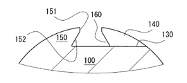
- the receiving recess 160 provided in the first engagement protrusion 140 and the second engagement protrusion 150 is configured by one inclined surface 142, 152 and a flat surface 130, unlike the first embodiment. The Even in such a case, the same effect as that of the first embodiment can be obtained.
- FIG. 13 is a partial cross-sectional schematic view of the skin material showing the configuration of the side edge portion of the skin material of the steering wheel.
- FIG. 14 is a schematic partial sectional view of the steering wheel.
- the side edge portion 210 of the skin material 200 has a huge portion 220 having a thickness increased as compared with the thickness of the skin material.
- the enormous portion 220 is held between the first engagement protrusion row 110 and the elastic member 300, and between the second engagement protrusion row 120 and the elastic member 300, and the outer skin member 200 to the steering wheel annular portion 100 is stronger. Mounting is ensured.
- the enormous portion 220 provided on the side edge portion 210 of the skin material 200 is formed by folding the skin material 200 so as to wrap the wire 221 and sewing it.
- the enormous portion 220 has a stitched portion 222 in which the skin material 200 is laminated and stitched together, and this portion is between the first engagement protrusion 140 and the elastic member 300 and between the second engagement protrusion 150 and the elastic member 300. It is possible to prevent the seam of the stitching portion 222 from being unraveled.
- the wire 221 is, for example, a flexible metal wire. In the state shown in FIG. 14, the wire 221 is disposed in the receiving recess 160. In order for the wire 221 to exit the receiving recess 160, it is necessary to overcome the step of the engaging protrusion.
- FIG. 15 is a partial cross-sectional schematic view of the skin material showing the configuration of the side edge portion of the skin material of the steering wheel.
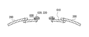
- the fastener stringer 600 is stitched to the side edge portion 210 of the skin material 200, and the fastener element 620 of the fastener stringer 600 functions as the enormous portion 220. Even in such a case, the same effect as the third embodiment can be obtained.
- the fastener stringer 600 has a fastener tape 610.
- One side edge of the fastener tape 610 is stitched to the side edge 210 of the skin material 200.
- a fastener element 620 is provided on the other side edge of the fastener tape 610.
- the fastener element 620 is a coil element, for example, and is stitched to the fastener tape 610.
- the fastener elements are metal or resin elements, and are arranged at regular intervals along the circumferential direction.
Landscapes
- Engineering & Computer Science (AREA)
- Chemical & Material Sciences (AREA)
- Combustion & Propulsion (AREA)
- Transportation (AREA)
- Mechanical Engineering (AREA)
- Steering Controls (AREA)
Abstract
ステアリングホイール環状部(100)が、第1係合突起列(110)及び第2係合突起列(120)を含む。第1係合突起列(110)が、第1間隔(W1)をあけて配列された複数の第1係合突起(140)を含む。第2係合突起列(120)が、第2間隔(W2)をあけて配列された複数の第2係合突起(150)を含む。第1係合突起(140)及び第2係合突起(150)が周方向に沿って互い違いに配列される。周方向に沿う第1係合突起(140)の幅(W140)が、周方向に沿う第2間隔(W2)の幅以下である。周方向に沿う第2係合突起(150)の幅(W150)が、周方向に沿う第1間隔(W1)の幅以下である。
Description
本開示は、ステアリングホイールに関する。
特許文献1には、同文献の図1乃至7に示すように、ステアリングホイールのリムの凹部に対して挿入片を用いて可撓性カバーを固定する技術が開示されている。
特許文献2は、リング部被覆層に長溝が形成され、長溝内にばね部材が収容され、バネ部材の側壁の間に小ピース部材が圧入される構成が開示されている。
本願発明者らは、新規な構造のステアリングホイール環状部の提供の意義を見出した。
本発明の一態様に係るステアリングホイールは、ステアリングホイール環状部(100)と、前記ステアリングホイール環状部(100)に対して表皮材(200)を止着するための弾性部材(300)を備えるステアリングホイール(400)であって、
前記ステアリングホイール環状部(100)が、前記弾性部材(300)及び前記表皮材(200)の側縁部を保持するべく設けられた第1係合突起列(110)及び第2係合突起列(120)を含み、前記第1係合突起列(110)が、第1間隔(W1)をあけて配列された複数の第1係合突起(140)を含み、前記第2係合突起列(120)が、第2間隔(W2)をあけて配列された複数の第2係合突起(150)を含み、前記第1係合突起(140)及び前記第2係合突起(150)が周方向に沿って互い違いに配列され、
周方向に沿う前記第1係合突起(140)の幅(W140)が、周方向に沿う前記第2間隔(W2)の幅以下であり、周方向に沿う前記第2係合突起(150)の幅(W150)が、周方向に沿う前記第1間隔(W1)の幅以下である。
前記ステアリングホイール環状部(100)が、前記弾性部材(300)及び前記表皮材(200)の側縁部を保持するべく設けられた第1係合突起列(110)及び第2係合突起列(120)を含み、前記第1係合突起列(110)が、第1間隔(W1)をあけて配列された複数の第1係合突起(140)を含み、前記第2係合突起列(120)が、第2間隔(W2)をあけて配列された複数の第2係合突起(150)を含み、前記第1係合突起(140)及び前記第2係合突起(150)が周方向に沿って互い違いに配列され、
周方向に沿う前記第1係合突起(140)の幅(W140)が、周方向に沿う前記第2間隔(W2)の幅以下であり、周方向に沿う前記第2係合突起(150)の幅(W150)が、周方向に沿う前記第1間隔(W1)の幅以下である。
幾つかの実施形態においては、前記ステアリングホイール環状部(100)が、各第1係合突起(140)及び各第2係合突起(150)が設けられる周方向に延びる主面(130)を備え、
前記第1係合突起(140)及び前記第2係合突起(150)は、各々、前記弾性部材(300)の一部を受け入れるべく前記主面(130)の幅方向において反対方向に窪んだ受入凹部(160)を有する。
前記第1係合突起(140)及び前記第2係合突起(150)は、各々、前記弾性部材(300)の一部を受け入れるべく前記主面(130)の幅方向において反対方向に窪んだ受入凹部(160)を有する。
幾つかの実施形態においては、前記表皮材(200)の前記側縁部は、前記表皮材(200)の他の部分の厚みに比べて大きい厚みを有する1以上の膨大部(210)を備える。
幾つかの実施形態においては、前記第1係合突起列(110)が前記ステアリングホイール(400)の手前側に設けられ、前記第2係合突起列(120)が前記ステアリングホイール(400)の奥手側に設けられる。
幾つかの実施形態においては、前記ステアリングホイール環状部(100)が、各第1係合突起(140)及び各第2係合突起(150)が設けられる周方向に延びる主面(130)を備え、
前記主面(130)が、前記ステアリングホイール(400)の半径方向内側を向くように配向される。
前記主面(130)が、前記ステアリングホイール(400)の半径方向内側を向くように配向される。
本発明の一態様によれば、第1及び第2係合突起列を備える新規な構造のステアリングホイール環状部を提供することができる。
以下、図面を参照しつつ、本発明の実施の形態について説明する。各実施形態は、個々に独立したものではなく、過剰説明をするまでもなく、当業者をすれば、適宜、組み合わせることが可能であり、この組み合わせによる相乗効果も把握可能である。実施形態間の重複説明は、原則的に省略する。参照図面は、発明説明を主目的とするものであり、適宜、簡略化されている。
周方向は、ステアリングホイール/ステアリングホイール環状部の形状に即して理解される。例えば、周方向は、ステアリングホイール環状部の中心軸AXを周囲する方向である。半径方向は、ステアリングホイール/ステアリングホイール環状部の形状に即して理解される。例えば、半径方向内側は、ステアリングホイール環状部からステアリングホイール環状部の中心軸AXに向かう方向である。半径方向外側は、半径方向内側とは反対側に向かう方向である。
<第1実施形態>
図1乃至図8を参照して第1実施形態について説明する。図1は、ステアリングホイールの概略的な正面図であり、略正円状のステアリングホイール環状部及びステアリングホイール環状部内のT字部が図示され、ステアリングホイール環状部の中心軸AXも模式的に示される。図2は、ステアリングホイールのステアリングホイール環状部の一部を取り出した概略的な部分分解斜視図であり、ステアリングホイール環状部の断面と、ステアリングホイール環状部の第1係合突起列と第2係合突起列の間に挿入されるべき弾性部材を併せて図示する。図3は、ステアリングホイールのステアリングホイール環状部の第1係合突起列と第2係合突起列を正面視した概略的な正面模式図である。図4は、ステアリングホイールのステアリングホイール環状部の概略的な部分断面模式図であり、図3のIV-IVに沿う部分断面を模式的に示す。図5は、ステアリングホイールのステアリングホイール環状部の概略的な部分断面模式図であり、図3のV-Vに沿う部分断面を模式的に示す。図6は、ステアリングホイールの概略的な部分断面模式図であり、第1係合突起列と第2係合突起列の間に弾性部材が挿入され、弾性部材と各係合突起列の間で表皮材の側縁部が保持され、ステアリングホイール環状部が表皮材により覆われた状態が模式的に示される。図7は、ステアリングホイールのステアリングホイール環状部の第1係合突起列と第2係合突起列を正面視した概略的な正面模式図であり、第1係合突起列と第2係合突起列の間に弾性部材が挿入され、弾性部材と各係合突起列の間で表皮材の側縁部が保持された状態が模式的に示される。図8は、ステアリングホイールのステアリングホイール環状部の製造に用いられる金型の概略的な断面模式図である。
図1乃至図8を参照して第1実施形態について説明する。図1は、ステアリングホイールの概略的な正面図であり、略正円状のステアリングホイール環状部及びステアリングホイール環状部内のT字部が図示され、ステアリングホイール環状部の中心軸AXも模式的に示される。図2は、ステアリングホイールのステアリングホイール環状部の一部を取り出した概略的な部分分解斜視図であり、ステアリングホイール環状部の断面と、ステアリングホイール環状部の第1係合突起列と第2係合突起列の間に挿入されるべき弾性部材を併せて図示する。図3は、ステアリングホイールのステアリングホイール環状部の第1係合突起列と第2係合突起列を正面視した概略的な正面模式図である。図4は、ステアリングホイールのステアリングホイール環状部の概略的な部分断面模式図であり、図3のIV-IVに沿う部分断面を模式的に示す。図5は、ステアリングホイールのステアリングホイール環状部の概略的な部分断面模式図であり、図3のV-Vに沿う部分断面を模式的に示す。図6は、ステアリングホイールの概略的な部分断面模式図であり、第1係合突起列と第2係合突起列の間に弾性部材が挿入され、弾性部材と各係合突起列の間で表皮材の側縁部が保持され、ステアリングホイール環状部が表皮材により覆われた状態が模式的に示される。図7は、ステアリングホイールのステアリングホイール環状部の第1係合突起列と第2係合突起列を正面視した概略的な正面模式図であり、第1係合突起列と第2係合突起列の間に弾性部材が挿入され、弾性部材と各係合突起列の間で表皮材の側縁部が保持された状態が模式的に示される。図8は、ステアリングホイールのステアリングホイール環状部の製造に用いられる金型の概略的な断面模式図である。
図1乃至図8から理解されるように、ステアリングホイール400は、表皮材200により被覆される環状のステアリングホイール環状部100を有する。ステアリングホイール環状部100は、中心軸AX周りに正円状のリング体であるが、他の実施形態においては、楕円形状等の任意の他の形状も採用され得る。ステアリングホイール400は、ステアリングホイール環状部100に加えて環内のT字部199を有する。T字部199は、ステアリングホイール環状部100の補強若しくは操作部の配置のために設けられる。操作部は、ステアリングホイール400が取り付けられる不図示の車両制御部に対する各種の指令を入力するための入力装置である。他の実施形態においては、T字部199の構成が変更又は省略される。
ステアリングホイール環状部100の被覆材である表皮材200は、天然皮革、人工皮革、織物、編み物、及び樹脂シートのいずれか一つ又はこれらの任意の組み合わせが例示できる。
図2には、ステアリングホイール環状部100と、ステアリングホイール環状部100に対して表皮材200を止着するための弾性部材300が図示される。ステアリングホイール環状部100は、略正円若しくは楕円形の断面を有し、また滑らかな曲面の外面を有する。ステアリングホイール環状部100は、その断面図から理解できるように、コア部180、及びコア部180を被覆するシェル部185を有する。シェル部185内にはコア部180が埋め込まれる。コア部180は、ステアリングホイール環状部100の強度確保のために設けられる。コア部180は、例えば、金属製若しくは繊維強化樹脂などの高強度材料から成る。シェル部185は、コア部180と比較して剛性が低い材料から成る。シェル部185は、例えば、合成ゴム、ウレタン樹脂、ポリプロピレン及びこれらの任意の組み合わせから選択される材料から成る。弾性部材300は、弾性を有する樹脂、例えば、合成ゴム、ウレタン樹脂、ポリプロピレン及びこれらの任意の組み合わせから選択される。
図2に示すように、ステアリングホイール環状部100は、弾性部材300及び表皮材200の側縁部210を保持するべく隣接して設けられた第1係合突起列110及び第2係合突起列120を有する。ステアリングホイール環状部100は、ステアリングホイール環状部100の部分的除去により形成された態様の平坦面130を有する。平坦面130は、第1係合突起列110、端的には後述の各第1係合突起140と、第2係合突起列120、端的には後述の各第2係合突起150が設けられた周方向に延びる主面130の一態様である。平坦面130は、ステアリングホイール環状部100を部分的に除去することにより形成される必要はなく、後述のような金型装置に活用して成形することができる。平坦面130は必ずしも平坦である必要はなく、他の実施形態においては非平坦面であり得る。
第1係合突起列110は、第1間隔W1をあけて配列された複数の第1係合突起140を有する。他方、第2係合突起列120は、第2間隔W2をあけて配列された複数の第2係合突起150を含む。図示例においては各第1係合突起及び各第2係合突起150が共通の平坦面130上に設けられる。
第1係合突起列110が周方向に沿って設けられる。第2係合突起列120が周方向に沿って設けられる。第1係合突起列110及び第2係合突起列120は、周方向に並走する態様にある。ステアリングホイール環状部100の中心軸AXに沿う方向において第1係合突起列110と第2係合突起列120がお互いに異なる位置にある。第1係合突起列110の各第1係合突起140は、平坦面130から半径方向内側へ突出する態様にある。第2係合突起列120の各第2係合突起150は、平坦面130から半径方向内側へ突出する態様にある。各第1係合突起140の外面は、第1係合突起140以外のステアリングホイール環状部100の部分の滑らかな曲面の外面と同一の曲面を形成する。各第2係合突起150の外面は、第2係合突起150以外のステアリングホイール環状部100の部分の滑らかな曲面の外面と同一の曲面を形成する。
各第1係合突起140は、平坦面130に対して垂直な側面141を有する。各第2係合突起150は、平坦面130に対して垂直な側面151を有する。ステアリングホイール環状部100の中心軸AXに沿う方向において第1係合突起140の側面141と第2係合突起150の側面151がお互いに反対方向に臨む。第1係合突起140の側面141と第2係合突起150の側面151が、周方向において互い違いに配置され、これにより第1係合突起列110と第2係合突起列120の間での弾性部材300及び各側縁部210の保持が達成される。なお、他の実施形態においては、第1係合突起140の側面141が非平坦であり、若しくは平坦面130に対して非垂直であることが予期される。同様に、第2係合突起150の側面151が非平坦であり、若しくは平坦面130に対して非垂直であることが予期される。
図2に示す非限定の例示形態では、平坦面130が半径方向内側を臨むように配向される。また、第1係合突起列110が、ステアリングホイール400の手前側に設けられ、第2係合突起列120が、ステアリングホイール400の奥手側に設けられる。ステアリングホイール400の手前側が矢印FWにより示され、ステアリングホイール400の奥手側が矢印RWにより示される。ステアリングホイール400は、通常、運転手側に向く手前側と、この反対側の奥手側を有する。
他の実施形態においては、平坦面130が半径方向外側を臨むように配向され得る。この場合においても、第1係合突起列110が、ステアリングホイール400の手前側に設けられ、第2係合突起列120が、ステアリングホイール400の奥手側に設けられる。若しくは、第1係合突起列110が、ステアリングホイール400の奥手側に設けられ、第2係合突起列120が、ステアリングホイール400の手前側に設けられる。他の更なる実施形態においては、平坦面130が、ステアリングホイール400の手前側若しくは奥手側を臨むように配向され、第1係合突起列110/第2係合突起列120が半径方向内側/半径方向外側に配置され得る。
第1係合突起140及び第2係合突起150が周方向に沿って互い違い/交互に配列される。第1係合突起140及び第2係合突起150が周方向において千鳥状/ジグザグ状に配列されるとも理解できる。かかる各係合突起の配列は、特許文献1及び2のような長溝よりも視認性が高く、組み立て作業の効率化に貢献し得る。かかる各係合突起の配列がステアリングホイール環状部100の製造の観点からも好ましい。ステアリングホイール環状部100に特許文献1及び2のような長溝を設ける場合、金型装置の構成が複雑化し得る。
周方向における第1係合突起140の配置間隔が周方向における第2係合突起150の配置間隔と同一である必要はなく、幾つかの実施形態においては、周方向における第1係合突起140の配置間隔が周方向における第2係合突起150の配置間隔とは異なる。
図3に示すように、非限定の例示形態においては、周方向沿いに隣接する第1係合突起140の間隔が第1間隔W1であり、周方向沿いに隣接する第2係合突起150の間隔が第2間隔W2である。第1係合突起140は、周方向沿いの幅W140を有する。第2係合突起150は、周方向沿いの幅W150を有する。
本実施形態においては、第1係合突起140の幅W140が第2間隔W2以下であり、第2係合突起150の幅W150が第1間隔W1以下である。図3の非限定の例示形態においては、第1係合突起140の幅W140が第2間隔W2に等しく、第2係合突起150の幅W150が第1間隔W1に等しい。このような寸法関係を満足することでステアリングホイール環状部100を比較的に簡単な構成の金型で製造することが許容される。
なお、図3に示す時、第1係合突起140の幅W140が第2係合突起150の幅W150に等しい。従って、W140=W150=W1=W2の関係が満足する。他の実施形態においては、必ずしも、この関係が満足されない。
弾性部材300が第1係合突起140と第2係合突起列120の間に挿入され、これにより、図6に示すように短幅の表皮材200の一方の側縁部210が第1係合突起140と弾性部材300の間で保持され、短幅の表皮材200の他方の側縁部210が第2係合突起列120と弾性部材300の間で保持される。弾性部材300と第1係合突起140の協力及び弾性部材300と第2係合突起列120の協力に基づいて、第1係合突起列110と第2係合突起列120の間で、弾性部材300及び弾性部材300の両側の側縁部210の保持が確保される。
ある方法においては、第1係合突起140と第2係合突起列120の間への弾性部材300の挿入時に第1係合突起140と第2係合突起列120の間へ表皮材200を連行させる。他の方法においては、第1係合突起140と第2係合突起列120の間に表皮材200の各側縁部210を配置した状態で、第1係合突起140と第2係合突起列120の間へ弾性部材300を挿入する。第1係合突起140と第2係合突起列120の間に弾性部材300が進入するに従い、ステアリングホイール環状部100の外面上で表皮材200が張られ、ステアリングホイール環状部100の外面に表皮材200が密着する。表皮材200により周方向に隣接する第1係合突起140の間の隙間も被覆される。同様に、表皮材200により周方向に隣接する第2係合突起150の間の隙間も被覆される。ステアリングホイール環状部100を表皮材200で被覆することで、ステアリングホイール400の把持感触の改善、ステアリングホイール400の意匠性の改善等が促進される。
幾つかの実施形態においては、周方向に隣接する第1係合突起140の間の隙間と周方向に隣接する第2係合突起150の間の隙間に充填剤が配される。幾つかの実施形態においては、ステアリングホイール環状部100の外面と表皮材200の間に接着層が挿入される。
図3に示すように、第1係合突起列110と第2係合突起列120の間には第3間隔W3が設けられる。第3間隔W3は、第1間隔W1や第2間隔W2よりも狭い。他の実施形態においては、第3間隔W3が、第1間隔W1や第2間隔W2よりも大きい。第1係合突起列110と第2係合突起列120の間には第3間隔W3の幅で周方向に直線的に延びる通路が存在する。周方向にて隣接する第1係合突起140の間の隙間のため、また周方向にて隣接する第2係合突起150の間の隙間のため、上述の通路の幅が周方向に沿って変動するとも理解できる。この通路の幅は、ステアリングホイール環状部100の中心軸AXに沿う方向の平坦面130の幅に等しい。平坦面130は、第1係合突起140及び第2係合突起150により周方向に沿って交互に幅が減じられる。つまり、平坦面130は、周方向に延びる過程で変動する幅を有する。
弾性部材300は、周方向に長く延びる長尺体である。弾性部材300は、第1係合突起列110と第2係合突起列120の間の第3間隔W3の幅の通路へ挿入/圧入される。弾性部材300は、図2に示すように、幅広の頭部310、幅狭の胴部320、及び一対の脚部330を有する。各脚部330は、弾性部材300の幅方向に突出する突起を有する。一対の脚部330の間には隙間が、各脚部330の相対変位が許容される。
図4乃至6に示すように、第1係合突起140と第2係合突起150は、各々、弾性部材300の一部、端的には、その脚部330の突起を受け入れるべく平坦面130の幅方向において反対方向に窪んだ受入凹部160を有する。第1係合突起140にはステアリングホイール400の手前側に深さW4だけ窪んだ第1受入凹部160が設けられる。第2係合突起150にはステアリングホイール400の奥手側に深さW4だけ窪んだ第2受入凹部160が設けられる。各係合突起に受入凹部160を設け、これにより各係合突起と弾性部材300の係合を強化し、第1係合突起列110と第2係合突起列120の間から弾性部材300が外れることが効果的に抑制される。図示例においては、平坦面130が受入凹部160の一側面を構成するが、必ずしもこの限りではない。
第1係合突起140には平坦面130上に突出し、平坦面130との間に受入空間を定める突出部145が含まれる。第2係合突起150には平坦面130上に突出し、平坦面130との間に受入空間を定める突出部155が含まれる。第1係合突起140の突出部145と第2係合突起150の突出部155は、平坦面130の幅方向において反対方向に突出する。
受入凹部160が深さW4の凹部を有し、これにより上述の通路の幅が、第3間隔W3+深さW4=幅W5に増加されるものと理解できる。ステアリングホイール環状部100には、周方向においてステアリングホイール400の手前側と奥手側に交互にシフトしながら進む幅W5の空間が存在すると理解できる。
図7は、図6のVII-VIIに沿う断面模式図が示される。図7に示すように、弾性部材300と弾性部材300の両隣に配される表皮材200の各側縁部210は、周方向に沿って僅かに蛇行して進む。斬新な意匠的効果が得られる。この蛇行態様の程度は、第1係合突起140や第2係合突起列120の配置間隔、及び/又は第1係合突起列110と第2係合突起列120の間隔の調整により調整可能である。
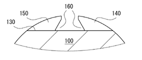
ステアリングホイール環状部100は、金型を用いて製造可能である。図8に示すように、一組の金型を用いてステアリングホイール環状部100が成形可能である。例えば、図8(a)の金型若しくは金型部分により図4に示す断面構造が成形される。例えば、図8(b)の金型若しくは金型部分により図5に示す断面構造が成形される。
図8(a)に示すように、第2金型520には半円状凹部が設けられる。第1金型510には、半円状凹部が設けられ、また上述の平坦面130を形成するための第1平坦面511、上述の受入凹部160を形成するための凸部512、及び上述の平坦面130に対して垂直な側面141を形成するための第2平坦面513が設けられる。第2平坦面513は、第1金型510と第2金型520の型割面と面一である。凸部512は、第2平坦面513から第2金型520のキャビティー内に突出する部分である。第1平坦面511は、第1金型510と第2金型520の型割面や第2平坦面513に対して垂直な平坦面であり、凸部512と第1金型510の半円状凹部を規定する曲面の間を接続する。
図8(b)に示すように、第1金型510には半円状凹部が設けられる。第2金型520には、半円状凹部が設けられ、また上述の平坦面130を形成するための第1平坦面521、上述の受入凹部160を形成するための凸部522、及び上述の平坦面130に対して垂直な側面151を形成するための第2平坦面523が設けられる。第2平坦面523は、第1金型510と第2金型520の型割面と面一である。凸部522は、第2平坦面523から第1金型510のキャビティー内に突出する部分である。第1平坦面521は、第1金型510と第2金型520の型割面や第2平坦面523に対して垂直な平坦面であり、凸部522と第2金型520の半円状凹部を規定する曲面の間を接続する。
図8(a)、(b)においては、ステアリングホイール環状部100のコア部180の図示が省略されている。
<第2実施形態>
図9乃至図12を参照して第2実施形態について説明する。図9は、ステアリングホイールのステアリングホイール環状部の第1係合突起列と第2係合突起列を正面視した概略的な正面模式図である。図10は、ステアリングホイールのステアリングホイール環状部の概略的な部分断面模式図であり、図9のX-Xに沿う部分断面を模式的に示す。図11は、ステアリングホイールのステアリングホイール環状部の概略的な部分断面模式図であり、図9のXI-XIに沿う部分断面を模式的に示す。図12は、ステアリングホイールのステアリングホイール環状部の概略的な部分断面模式図であり、図9のXII-XIIに沿う部分断面を模式的に示す。
図9乃至図12を参照して第2実施形態について説明する。図9は、ステアリングホイールのステアリングホイール環状部の第1係合突起列と第2係合突起列を正面視した概略的な正面模式図である。図10は、ステアリングホイールのステアリングホイール環状部の概略的な部分断面模式図であり、図9のX-Xに沿う部分断面を模式的に示す。図11は、ステアリングホイールのステアリングホイール環状部の概略的な部分断面模式図であり、図9のXI-XIに沿う部分断面を模式的に示す。図12は、ステアリングホイールのステアリングホイール環状部の概略的な部分断面模式図であり、図9のXII-XIIに沿う部分断面を模式的に示す。
本実施形態においては、第1実施形態のものと比較して、周方向における第1係合突起140の幅W140が小さく、周方向における第2係合突起列120の幅W150が小さく、周方向沿いに隣接する第1係合突起140の第1間隔の値が大きく、同様に、周方向沿いに隣接する第1係合突起140の第1間隔の値が大きい。W140=W150,W1=W2,W140<W1、W140<W2、W150<W1、W150<W2の関係が満足される。このような実施形態においても第1実施形態のものと同様の効果を得ることができる。
本実施形態においては、第1係合突起140や第2係合突起150に設けられる受入凹部160が、第1実施形態のものとは異なり、一つの斜面142、152と平坦面130により構成される。このような場合においても第1実施形態のものと同様の効果を得ることができる。
<第3実施形態>
図13及び図14を参照して第3実施形態について説明する。図13は、ステアリングホイールの表皮材の側縁部の構成を示す表皮材の部分断面模式図である。図14は、ステアリングホイールの部分断面模式図である。
図13及び図14を参照して第3実施形態について説明する。図13は、ステアリングホイールの表皮材の側縁部の構成を示す表皮材の部分断面模式図である。図14は、ステアリングホイールの部分断面模式図である。
本実施形態においては、表皮材200の側縁部210が表皮材の厚みに比して増加した厚みの膨大部220を有する。第1係合突起列110と弾性部材300の間、及び第2係合突起列120と弾性部材300の間で膨大部220が保持され、ステアリングホイール環状部100への表皮材200のより強固な取付が確保される。
図13及び図14に示すように、表皮材200の側縁部210に設けられた膨大部220は、線材221を包むように表皮材200が折り返されて縫われて成る。膨大部220は、表皮材200が積層されて縫い合わされた縫合部222を有し、この部分が、第1係合突起140と弾性部材300の間及び第2係合突起150と弾性部材300の間に挟み込まれ、縫合部222の縫い目が解けることが抑制される。
線材221は、例えば、可撓性を有する金属線である。図14に示す状態の時、線材221が受入凹部160内に配される。線材221が受入凹部160から出るためには係合突起の段差を乗り越える必要がある。
<第4実施形態>
図15を参照して第4実施形態について説明する。図15は、ステアリングホイールの表皮材の側縁部の構成を示す表皮材の部分断面模式図である。
図15を参照して第4実施形態について説明する。図15は、ステアリングホイールの表皮材の側縁部の構成を示す表皮材の部分断面模式図である。
本実施形態においては、表皮材200の側縁部210にファスナーストリンガー600が縫合され、ファスナーストリンガー600のファスナーエレメント620が膨大部220として機能する。このような場合においても第3実施形態と同様な効果を得ることができる。
なお、ファスナーストリンガー600は、ファスナーテープ610を有する。ファスナーテープ610の一方の側縁部が、表皮材200の側縁部210に縫合される。ファスナーテープ610の他方の側縁部にはファスナーエレメント620が設けられる。ファスナーエレメント620は、例えば、コイルエレメントであり、ファスナーテープ610に対して縫合される。他の実施形態においては、ファスナーエレメントが、金属製又は樹脂製のエレメントであり、周方向に沿って一定間隔で配列される。
上述の教示を踏まえると、当業者をすれば、各実施形態に対して様々な変更を加えることができる。請求の範囲に盛り込まれた符号は、参考のためであり、請求の範囲を限定解釈する目的で参照されるべきものではない。
400 ステアリングホイール
100 ステアリングホイール環状部
200 表皮材
300 弾性部材
110 第1係合突起列
120 第2係合突起列
130 平坦面
140 第1係合突起
150 第2係合突起
160 受入凹部
100 ステアリングホイール環状部
200 表皮材
300 弾性部材
110 第1係合突起列
120 第2係合突起列
130 平坦面
140 第1係合突起
150 第2係合突起
160 受入凹部
Claims (5)
- ステアリングホイール環状部(100)と、前記ステアリングホイール環状部(100)に対して表皮材(200)を止着するための弾性部材(300)を備えるステアリングホイール(400)であって、
前記ステアリングホイール環状部(100)が、前記弾性部材(300)及び前記表皮材(200)の側縁部を保持するべく設けられた第1係合突起列(110)及び第2係合突起列(120)を含み、前記第1係合突起列(110)が、第1間隔(W1)をあけて配列された複数の第1係合突起(140)を含み、前記第2係合突起列(120)が、第2間隔(W2)をあけて配列された複数の第2係合突起(150)を含み、前記第1係合突起(140)及び前記第2係合突起(150)が周方向に沿って互い違いに配列され、
周方向に沿う前記第1係合突起(140)の幅(W140)が、周方向に沿う前記第2間隔(W2)の幅以下であり、周方向に沿う前記第2係合突起(150)の幅(W150)が、周方向に沿う前記第1間隔(W1)の幅以下である、ステアリングホイール。 - 前記ステアリングホイール環状部(100)が、各第1係合突起(140)及び各第2係合突起(150)が設けられる周方向に延びる主面(130)を備え、
前記第1係合突起(140)及び前記第2係合突起(150)は、各々、前記弾性部材(300)の一部を受け入れるべく前記主面(130)の幅方向において反対方向に窪んだ受入凹部(160)を有する、請求項1に記載のステアリングホイール。 - 前記表皮材(200)の前記側縁部は、前記表皮材(200)の他の部分の厚みに比べて大きい厚みを有する1以上の膨大部(220)を備える、請求項1又は2に記載のステアリングホイール。
- 前記第1係合突起列(110)が前記ステアリングホイール(400)の手前側に設けられ、前記第2係合突起列(120)が前記ステアリングホイール(400)の奥手側に設けられる、請求項1乃至3のいずれか一項に記載のステアリングホイール。
- 前記ステアリングホイール環状部(100)が、各第1係合突起(140)及び各第2係合突起(150)が設けられる周方向に延びる主面(130)を備え、
前記主面(130)が、前記ステアリングホイール(400)の半径方向内側を向くように配向される、請求項1乃至4のいずれか一項に記載のステアリングホイール。
Priority Applications (1)
| Application Number | Priority Date | Filing Date | Title |
|---|---|---|---|
| PCT/JP2015/056126 WO2016139738A1 (ja) | 2015-03-02 | 2015-03-02 | ステアリングホイール |
Applications Claiming Priority (1)
| Application Number | Priority Date | Filing Date | Title |
|---|---|---|---|
| PCT/JP2015/056126 WO2016139738A1 (ja) | 2015-03-02 | 2015-03-02 | ステアリングホイール |
Publications (1)
| Publication Number | Publication Date |
|---|---|
| WO2016139738A1 true WO2016139738A1 (ja) | 2016-09-09 |
Family
ID=56849274
Family Applications (1)
| Application Number | Title | Priority Date | Filing Date |
|---|---|---|---|
| PCT/JP2015/056126 Ceased WO2016139738A1 (ja) | 2015-03-02 | 2015-03-02 | ステアリングホイール |
Country Status (1)
| Country | Link |
|---|---|
| WO (1) | WO2016139738A1 (ja) |
Citations (5)
| Publication number | Priority date | Publication date | Assignee | Title |
|---|---|---|---|---|
| JPS5739921A (en) * | 1980-08-23 | 1982-03-05 | Sumitomo Electric Ind Ltd | Half split type heat-shrinkable tube |
| JPS61132463A (ja) * | 1984-11-30 | 1986-06-19 | Toyoda Gosei Co Ltd | ステアリングホイ−ル |
| JPS63165268U (ja) * | 1986-06-27 | 1988-10-27 | ||
| WO2013029727A1 (de) * | 2011-09-01 | 2013-03-07 | Audi Ag | Anordnung zum verkleiden eines bauteils, bauteil und kraftfahrzeug |
| JP2014151776A (ja) * | 2013-02-08 | 2014-08-25 | Toyoda Gosei Co Ltd | ステアリングホイール |
-
2015
- 2015-03-02 WO PCT/JP2015/056126 patent/WO2016139738A1/ja not_active Ceased
Patent Citations (5)
| Publication number | Priority date | Publication date | Assignee | Title |
|---|---|---|---|---|
| JPS5739921A (en) * | 1980-08-23 | 1982-03-05 | Sumitomo Electric Ind Ltd | Half split type heat-shrinkable tube |
| JPS61132463A (ja) * | 1984-11-30 | 1986-06-19 | Toyoda Gosei Co Ltd | ステアリングホイ−ル |
| JPS63165268U (ja) * | 1986-06-27 | 1988-10-27 | ||
| WO2013029727A1 (de) * | 2011-09-01 | 2013-03-07 | Audi Ag | Anordnung zum verkleiden eines bauteils, bauteil und kraftfahrzeug |
| JP2014151776A (ja) * | 2013-02-08 | 2014-08-25 | Toyoda Gosei Co Ltd | ステアリングホイール |
Similar Documents
| Publication | Publication Date | Title |
|---|---|---|
| US11713802B2 (en) | Alternating tooth chain ring | |
| US10933781B2 (en) | Trim cover for a seat belt buckle hole | |
| WO2016139739A1 (ja) | ステアリングホイール及びその製造方法 | |
| US12053418B2 (en) | Goggle strap retention system | |
| JP2016514525A (ja) | 三次元の凸部を備える収納具 | |
| JP2008222038A (ja) | 非空気式タイヤ | |
| JP5959333B2 (ja) | かつらベース、及び、かつら | |
| KR101884053B1 (ko) | 랙 및 랙의 제조 방법 | |
| JP6002367B2 (ja) | 合体ワイヤハーネス | |
| JP2016175600A (ja) | 車両用内装部品 | |
| EP3476621B1 (en) | Joining element for bicycle rims, bicycle rim incorporating such a joining element and method for producing a respective rim | |
| JP4929245B2 (ja) | 工具類のグリップ | |
| US20170267072A1 (en) | Trim panel assemblies of a vehicle and methods of assembling the same | |
| JP2018070192A (ja) | 結束バンド及び外装部材付ワイヤーハーネス | |
| JP2008254689A (ja) | ステアリングホイール | |
| JP5949198B2 (ja) | リングブラシ及びブラシロール、ブラシ式路面清掃車 | |
| JP6017864B2 (ja) | 釣竿用筒状部材とその製法 | |
| JP6114801B1 (ja) | かつら取付具、及び、かつら | |
| JP6664289B2 (ja) | 弾性クローラ | |
| JP6404085B2 (ja) | 更生管用部材 | |
| JP5913769B2 (ja) | 車両用グリップ構造 | |
| JP7848031B2 (ja) | 表皮材、軸部材ユニットおよび表皮材の巻付け方法 | |
| JP6298733B2 (ja) | 切欠き補強部材 | |
| JP5946148B2 (ja) | 板状部材の連結構造、板状部材の連結方法、および板状部材 | |
| JP2014151863A (ja) | ステアリングホイール |
Legal Events
| Date | Code | Title | Description |
|---|---|---|---|
| 121 | Ep: the epo has been informed by wipo that ep was designated in this application |
Ref document number: 15883906 Country of ref document: EP Kind code of ref document: A1 |
|
| NENP | Non-entry into the national phase |
Ref country code: DE |
|
| NENP | Non-entry into the national phase |
Ref country code: JP |
|
| 122 | Ep: pct application non-entry in european phase |
Ref document number: 15883906 Country of ref document: EP Kind code of ref document: A1 |