WO2016136994A1 - すべり軸受の製造方法及びすべり軸受 - Google Patents
すべり軸受の製造方法及びすべり軸受 Download PDFInfo
- Publication number
- WO2016136994A1 WO2016136994A1 PCT/JP2016/055949 JP2016055949W WO2016136994A1 WO 2016136994 A1 WO2016136994 A1 WO 2016136994A1 JP 2016055949 W JP2016055949 W JP 2016055949W WO 2016136994 A1 WO2016136994 A1 WO 2016136994A1
- Authority
- WO
- WIPO (PCT)
- Prior art keywords
- narrow groove
- lining layer
- manufacturing
- depth
- thickness
- Prior art date
- Legal status (The legal status is an assumption and is not a legal conclusion. Google has not performed a legal analysis and makes no representation as to the accuracy of the status listed.)
- Ceased
Links
Images

Classifications
-
- F—MECHANICAL ENGINEERING; LIGHTING; HEATING; WEAPONS; BLASTING
- F16—ENGINEERING ELEMENTS AND UNITS; GENERAL MEASURES FOR PRODUCING AND MAINTAINING EFFECTIVE FUNCTIONING OF MACHINES OR INSTALLATIONS; THERMAL INSULATION IN GENERAL
- F16C—SHAFTS; FLEXIBLE SHAFTS; ELEMENTS OR CRANKSHAFT MECHANISMS; ROTARY BODIES OTHER THAN GEARING ELEMENTS; BEARINGS
- F16C9/00—Bearings for crankshafts or connecting-rods; Attachment of connecting-rods
- F16C9/02—Crankshaft bearings
-
- F—MECHANICAL ENGINEERING; LIGHTING; HEATING; WEAPONS; BLASTING
- F16—ENGINEERING ELEMENTS AND UNITS; GENERAL MEASURES FOR PRODUCING AND MAINTAINING EFFECTIVE FUNCTIONING OF MACHINES OR INSTALLATIONS; THERMAL INSULATION IN GENERAL
- F16C—SHAFTS; FLEXIBLE SHAFTS; ELEMENTS OR CRANKSHAFT MECHANISMS; ROTARY BODIES OTHER THAN GEARING ELEMENTS; BEARINGS
- F16C17/00—Sliding-contact bearings for exclusively rotary movement
- F16C17/02—Sliding-contact bearings for exclusively rotary movement for radial load only
- F16C17/022—Sliding-contact bearings for exclusively rotary movement for radial load only with a pair of essentially semicircular bearing sleeves
-
- F—MECHANICAL ENGINEERING; LIGHTING; HEATING; WEAPONS; BLASTING
- F16—ENGINEERING ELEMENTS AND UNITS; GENERAL MEASURES FOR PRODUCING AND MAINTAINING EFFECTIVE FUNCTIONING OF MACHINES OR INSTALLATIONS; THERMAL INSULATION IN GENERAL
- F16C—SHAFTS; FLEXIBLE SHAFTS; ELEMENTS OR CRANKSHAFT MECHANISMS; ROTARY BODIES OTHER THAN GEARING ELEMENTS; BEARINGS
- F16C33/00—Parts of bearings; Special methods for making bearings or parts thereof
- F16C33/02—Parts of sliding-contact bearings
- F16C33/04—Brasses; Bushes; Linings
- F16C33/046—Brasses; Bushes; Linings divided or split, e.g. half-bearings or rolled sleeves
-
- F—MECHANICAL ENGINEERING; LIGHTING; HEATING; WEAPONS; BLASTING
- F16—ENGINEERING ELEMENTS AND UNITS; GENERAL MEASURES FOR PRODUCING AND MAINTAINING EFFECTIVE FUNCTIONING OF MACHINES OR INSTALLATIONS; THERMAL INSULATION IN GENERAL
- F16C—SHAFTS; FLEXIBLE SHAFTS; ELEMENTS OR CRANKSHAFT MECHANISMS; ROTARY BODIES OTHER THAN GEARING ELEMENTS; BEARINGS
- F16C33/00—Parts of bearings; Special methods for making bearings or parts thereof
- F16C33/02—Parts of sliding-contact bearings
- F16C33/04—Brasses; Bushes; Linings
- F16C33/06—Sliding surface mainly made of metal
- F16C33/10—Construction relative to lubrication
- F16C33/1025—Construction relative to lubrication with liquid, e.g. oil, as lubricant
- F16C33/103—Construction relative to lubrication with liquid, e.g. oil, as lubricant retained in or near the bearing
-
- F—MECHANICAL ENGINEERING; LIGHTING; HEATING; WEAPONS; BLASTING
- F16—ENGINEERING ELEMENTS AND UNITS; GENERAL MEASURES FOR PRODUCING AND MAINTAINING EFFECTIVE FUNCTIONING OF MACHINES OR INSTALLATIONS; THERMAL INSULATION IN GENERAL
- F16C—SHAFTS; FLEXIBLE SHAFTS; ELEMENTS OR CRANKSHAFT MECHANISMS; ROTARY BODIES OTHER THAN GEARING ELEMENTS; BEARINGS
- F16C33/00—Parts of bearings; Special methods for making bearings or parts thereof
- F16C33/02—Parts of sliding-contact bearings
- F16C33/04—Brasses; Bushes; Linings
- F16C33/06—Sliding surface mainly made of metal
- F16C33/10—Construction relative to lubrication
- F16C33/1025—Construction relative to lubrication with liquid, e.g. oil, as lubricant
- F16C33/106—Details of distribution or circulation inside the bearings, e.g. details of the bearing surfaces to affect flow or pressure of the liquid
- F16C33/1065—Grooves on a bearing surface for distributing or collecting the liquid
-
- F—MECHANICAL ENGINEERING; LIGHTING; HEATING; WEAPONS; BLASTING
- F16—ENGINEERING ELEMENTS AND UNITS; GENERAL MEASURES FOR PRODUCING AND MAINTAINING EFFECTIVE FUNCTIONING OF MACHINES OR INSTALLATIONS; THERMAL INSULATION IN GENERAL
- F16C—SHAFTS; FLEXIBLE SHAFTS; ELEMENTS OR CRANKSHAFT MECHANISMS; ROTARY BODIES OTHER THAN GEARING ELEMENTS; BEARINGS
- F16C33/00—Parts of bearings; Special methods for making bearings or parts thereof
- F16C33/02—Parts of sliding-contact bearings
- F16C33/04—Brasses; Bushes; Linings
- F16C33/06—Sliding surface mainly made of metal
- F16C33/10—Construction relative to lubrication
- F16C33/1025—Construction relative to lubrication with liquid, e.g. oil, as lubricant
- F16C33/106—Details of distribution or circulation inside the bearings, e.g. details of the bearing surfaces to affect flow or pressure of the liquid
- F16C33/107—Grooves for generating pressure
-
- F—MECHANICAL ENGINEERING; LIGHTING; HEATING; WEAPONS; BLASTING
- F16—ENGINEERING ELEMENTS AND UNITS; GENERAL MEASURES FOR PRODUCING AND MAINTAINING EFFECTIVE FUNCTIONING OF MACHINES OR INSTALLATIONS; THERMAL INSULATION IN GENERAL
- F16C—SHAFTS; FLEXIBLE SHAFTS; ELEMENTS OR CRANKSHAFT MECHANISMS; ROTARY BODIES OTHER THAN GEARING ELEMENTS; BEARINGS
- F16C33/00—Parts of bearings; Special methods for making bearings or parts thereof
- F16C33/02—Parts of sliding-contact bearings
- F16C33/04—Brasses; Bushes; Linings
- F16C33/06—Sliding surface mainly made of metal
- F16C33/12—Structural composition; Use of special materials or surface treatments, e.g. for rust-proofing
- F16C33/122—Multilayer structures of sleeves, washers or liners
- F16C33/125—Details of bearing layers, i.e. the lining
-
- F—MECHANICAL ENGINEERING; LIGHTING; HEATING; WEAPONS; BLASTING
- F16—ENGINEERING ELEMENTS AND UNITS; GENERAL MEASURES FOR PRODUCING AND MAINTAINING EFFECTIVE FUNCTIONING OF MACHINES OR INSTALLATIONS; THERMAL INSULATION IN GENERAL
- F16C—SHAFTS; FLEXIBLE SHAFTS; ELEMENTS OR CRANKSHAFT MECHANISMS; ROTARY BODIES OTHER THAN GEARING ELEMENTS; BEARINGS
- F16C33/00—Parts of bearings; Special methods for making bearings or parts thereof
- F16C33/02—Parts of sliding-contact bearings
- F16C33/04—Brasses; Bushes; Linings
- F16C33/06—Sliding surface mainly made of metal
- F16C33/14—Special methods of manufacture; Running-in
-
- F—MECHANICAL ENGINEERING; LIGHTING; HEATING; WEAPONS; BLASTING
- F16—ENGINEERING ELEMENTS AND UNITS; GENERAL MEASURES FOR PRODUCING AND MAINTAINING EFFECTIVE FUNCTIONING OF MACHINES OR INSTALLATIONS; THERMAL INSULATION IN GENERAL
- F16C—SHAFTS; FLEXIBLE SHAFTS; ELEMENTS OR CRANKSHAFT MECHANISMS; ROTARY BODIES OTHER THAN GEARING ELEMENTS; BEARINGS
- F16C2240/00—Specified values or numerical ranges of parameters; Relations between them
- F16C2240/30—Angles, e.g. inclinations
-
- F—MECHANICAL ENGINEERING; LIGHTING; HEATING; WEAPONS; BLASTING
- F16—ENGINEERING ELEMENTS AND UNITS; GENERAL MEASURES FOR PRODUCING AND MAINTAINING EFFECTIVE FUNCTIONING OF MACHINES OR INSTALLATIONS; THERMAL INSULATION IN GENERAL
- F16C—SHAFTS; FLEXIBLE SHAFTS; ELEMENTS OR CRANKSHAFT MECHANISMS; ROTARY BODIES OTHER THAN GEARING ELEMENTS; BEARINGS
- F16C2240/00—Specified values or numerical ranges of parameters; Relations between them
- F16C2240/40—Linear dimensions, e.g. length, radius, thickness, gap
- F16C2240/42—Groove sizes
Definitions
- the present invention relates to a technology of a sliding bearing manufacturing method, and more particularly to a technology of a sliding bearing manufacturing method in which a half member obtained by dividing a cylinder into two in parallel with an axial direction is arranged vertically.
- the present invention provides a plain bearing capable of suppressing the total amount of oil spilled and obtaining a further friction reduction effect.
- the manufacture of a plain bearing in which a cylinder is divided into two in parallel with the axial direction, and a half member having a metal layer and a lining layer provided on the inner peripheral surface of the metal layer is arranged vertically.
- the said manufacturing method has a 1st process which provides a narrow groove in the circumferential direction in the rotation direction downstream in the axial direction edge part of the said lower half member, Said 1st process The depth of the narrow groove is formed so as to be shorter than the thickness of the lining layer minus the sum of the tolerance of the thickness of the lining layer and the tolerance of the depth of the narrow groove. is there.
- the said manufacturing method has a 2nd process which provides a peripheral part in the axial direction edge part of the said lower half member, and the axial direction outer side of the said narrow groove, Said 2nd process
- the inner peripheral surface of the peripheral edge portion is formed closer to the inner peripheral side than the bottom surface of the narrow groove.
- the friction reduction effect can be obtained while reducing the sliding area, and the total amount of oil spilled can be suppressed.
- the depth of the narrow groove is formed by a blade such as a saw, the blade can be prevented from hitting a metal layer having a hardness higher than that of the lining layer, so that the life of the blade is extended.
- the narrow groove is provided only in the lining layer having a hardness capable of press molding, the narrow groove can be formed by press molding.
- the front view which shows the slide bearing which concerns on embodiment of this invention (A) The top view which shows the half member which comprises the slide bearing which concerns on embodiment of this invention. (B) Sectional view taken along line II (B) -II (B). (C) Sectional view taken along line II (C) -II (C). The flowchart figure which shows the manufacturing method of the half member which concerns on embodiment of this invention.
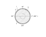
- FIG. 1 is a front view of the sliding bearing 1, where the top and bottom of the screen is the vertical direction, and the front and back directions of the screen are the axial directions (front and back directions).
- the slide bearing 1 is a cylindrical member and is applied to a slide bearing structure of an engine crankshaft 11 as shown in FIG.
- the plain bearing 1 is composed of two halved members 2 and 2.
- the two halved members 2 and 2 have a shape obtained by dividing a cylinder into two in parallel to the axial direction, and are formed so that the cross section is a semicircular shape.
- the half members 2 and 2 are arranged up and down, and mating surfaces are arranged on the left and right.
- FIG. 2 (A) the upper and lower half members 2 are shown.
- the rotation direction of the crankshaft 11 is the clockwise direction when viewed from the front as indicated by the arrow in FIG.
- the bearing angle ⁇ is 0 degree at the right end position in FIG. 2B, and the counterclockwise direction in FIG. 2B is positive. That is, in FIG. 2B, the bearing angle ⁇ at the left end position is defined as 180 degrees, and the bearing angle ⁇ at the lower end position is defined as 270 degrees.
- a groove is provided in the circumferential direction, and a circular hole is provided in the center.
- mating surfaces are arranged on the left and right of the upper half member 2.
- the half member 2 has a metal layer 21 and a lining layer 22 as shown in FIG.
- a narrow groove 3 is formed at the end in the axial direction.
- the peripheral edge 2a that forms the axially outer side surface of the narrow groove 3 has a height h from the outer peripheral surface of the half member 2 higher than the height D from the outer peripheral surface of the half member 2 to the contact surface. It is formed to be low. That is, the outer peripheral edge 2a in the axial direction is formed to be one step lower than the contact surface with the surrounding crankshaft 11.
- the narrow groove 3 will be described with reference to FIGS. 2B and 2C.
- the narrow groove 3 is provided in the lower half member 2.
- two narrow grooves 3 are provided in parallel in the axial direction.
- the narrow groove 3 is formed in a direction in which the bearing angle ⁇ is positive (counterclockwise) from a position (the bearing angle ⁇ is ⁇ 1) that is separated from the mating surface on the downstream side in the rotation direction of the crankshaft 11 (the bearing angle ⁇ is 180 degrees).
- the right mating surface in FIG. 2B is the upstream mating surface in the rotational direction
- the left mating surface in FIG. 2B is the downstream mating surface in the rotational direction.
- the width of the narrow groove 3 is formed to be w as shown in FIG. Further, the depth d of the narrow groove 3 is formed to be shorter than the height D from the outer peripheral surface of the half member 2 to the contact surface.
- peripheral edge 2a is formed so as to be one step higher than the bottom surface 3a of the narrow groove 3, it becomes a wall for preventing oil leaking from the sliding surface to the axial end and oil sucked back from leaking again. , Leakage oil amount can be suppressed. As a result, the amount of oil drawn in particularly during cold can be increased, and the low friction effect due to early temperature rise can be increased.
- peripheral edge portion 2a is formed so as to be one step lower than the contact surface with the surrounding crankshaft 11, the crankshaft 11 is inclined and is in contact with only one end portion in the axial direction. Since the chance of contact between the peripheral edge 2a and the crankshaft 11 can be reduced, damage to the peripheral edge 2a can be prevented.
- the provision of the narrow groove 3 according to the present embodiment increases the FMEP mitigation amount.
- the FMEP reduction amount increases in a region where the engine speed is low.
- FMEP is a value for seeing the tendency of friction, and the friction decreases as the FMEP reduction amount increases. For example, when the engine is cold started, the FMEP mitigation amount increases and friction is reduced.
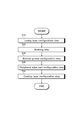
- the manufacturing method of the lower half member 2 includes a lining layer forming step S10 in which the lining layer 22 is pasted on the metal layer 21, a forming step S20 in which the lining layer 22 and the metal layer 21 are formed in a semicircular shape, A narrow groove forming step S30, which is the first step for forming the groove 3, a peripheral portion forming step S40, which is the second step for forming the peripheral portion 2a, and a coating layer (not shown) on the surface of the lining layer 22. Coating layer forming step S50. Below, each process is demonstrated concretely.
- the lining layer 22 is attached to the metal layer 21. More specifically, the lining layer 22 is attached to the metal layer 21 by applying a rolling process to the metal layer 21 and the lining layer 22.
- the metal layer 21 is made of a material made of metal, for example, a material made of an iron-based material.
- the lining layer 22 is comprised with the raw material which consists of a metal whose hardness is lower than the metal layer 21, for example, is comprised with the raw material which consists of an aluminum-type material.
- the metal layer 21 and the lining layer 22 are formed in a semicircular shape. More specifically, the metal layer 21 and the lining layer 22 are formed into a semicircular shape by press molding.
- the narrow groove 3 is formed in the narrow groove forming step S30. Further, in the peripheral edge forming step S40, the peripheral edge 2a is formed.
- the narrow groove forming step S30 the depth d of the narrow groove 3 is obtained by subtracting the sum of the thickness tolerance a1 of the lining layer 22 and the depth tolerance a2 of the narrow groove 3 from the thickness h1 of the lining layer 22. It is formed to be shorter than the length.
- the depth of the narrow groove 3 d is represented by d ⁇ h1- (a1 + a2).
- the peripheral edge forming step S40 since the inner peripheral surface 2c of the peripheral edge 2a is formed on the inner peripheral side with respect to the bottom surface 3a of the narrow groove 3, the peripheral edge 2a is also formed in the lining layer 22. Thereby, when forming the peripheral part 2a, since a blade does not contact the metal layer 21, the lifetime of a blade can be extended.
- the depth d of the narrow groove 3 is obtained by subtracting the sum of the thickness tolerance a1 of the lining layer 22 and the depth tolerance a2 of the narrow groove 3 from the thickness h1 of the lining layer 22. It is formed to be shorter than the length. With this configuration, the depth d of the narrow groove 3 is smaller than the thickness h1 of the lining layer 22.
- the fine groove 3 can be formed by press working.
- the inner peripheral surface 2c of the peripheral edge 2a is formed on the inner peripheral side with respect to the bottom surface 3a of the narrow groove 3, the inner peripheral surface 2c of the peripheral edge 2a is also formed in the lining layer 22. . Thereby, formation of the peripheral part 2a by press work is attained.
- a coating layer (not shown) is formed on the surface (inner peripheral surface) of the lining layer 22.
- the coating layer is made of a material made of a soft metal or a resin material.
- the cylinder is divided into two parallel to the axial direction, and the half member 2 or 2 having the metal layer 21 and the lining layer 22 provided on the inner peripheral surface of the metal layer 21 is vertically arranged.
- the narrow groove forming step S30 the depth d of the narrow groove 3 is changed from the thickness h1 of the lining layer 22 to the tolerance a1 of the thickness of the lining layer 22 and the depth of the narrow groove 3. It is formed to be shorter than the length obtained by subtracting the sum of the tolerances a2.
- the narrow groove 3 that does not hinder the generation of the oil film pressure, it is possible to obtain a friction reduction effect while reducing the sliding area, and to suppress the total amount of oil spilled. be able to.
- the depth d of the narrow groove 3 is made shorter than the length obtained by subtracting the sum of the thickness tolerance of the lining layer 22 from the thickness h1 of the lining layer 22 and the tolerance of the depth of the narrow groove 3 and a2.
- the narrow groove 3 is formed by a cutting tool such as a circular saw, it is possible to prevent the cutting tool from hitting the metal layer 21 having a hardness higher than that of the lining layer 22, so that the tool life is long.
- the narrow groove 3 is provided only in the lining layer 22 having a hardness capable of press molding, the narrow groove 3 can be formed by press molding.
- peripheral part formation process S40 (2nd process) which provides a peripheral part in the axial direction edge part of the lower half member 2, and the axial direction outer side of the narrow groove 3,
- peripheral part formation process S40 The inner peripheral surface 2c of the peripheral edge 2a is formed on the inner peripheral side with respect to the bottom surface 3a of the narrow groove 3.
- the present invention can be used for a technology of a sliding bearing manufacturing method, and can be used for a technology of a sliding bearing manufacturing method in which a half member in which a cylinder is divided into two in parallel with an axial direction is arranged vertically.
Landscapes
- Engineering & Computer Science (AREA)
- General Engineering & Computer Science (AREA)
- Mechanical Engineering (AREA)
- Chemical & Material Sciences (AREA)
- Oil, Petroleum & Natural Gas (AREA)
- Sliding-Contact Bearings (AREA)
- Shafts, Cranks, Connecting Bars, And Related Bearings (AREA)
Abstract
Description
すべり軸受1は円筒状の部材であり、図1に示すように、エンジンのクランクシャフト11のすべり軸受構造に適用される。すべり軸受1は、二つの半割部材2・2で構成されている。二つの半割部材2・2は、円筒を軸方向と平行に二分割した形状であり、断面が半円状となるように形成されている。本実施形態においては、半割部材2・2は上下に配置されており、左右に合わせ面が配置されている。クランクシャフト11をすべり軸受1で軸支する場合、所定の隙間が形成され、この隙間に対し図示せぬ油路から潤滑油が供給される。
下側の半割部材2の内周において、その軸方向の端部に細溝3が形成されている。
また、細溝3の軸方向外側面を形成する周縁部2aは、半割部材2の外周面からの高さhが、半割部材2の外周面から当接面までの高さDよりも低くなるように形成されている。すなわち、軸方向外側の周縁部2aが周囲のクランクシャフト11との当接面よりも一段低くなるように形成されている。
細溝3は下側の半割部材2に設けられる。本実施形態においては、細溝3は軸方向に並列して二本設けられている。詳細には、細溝3は、クランクシャフト11の回転方向下流側合わせ面(軸受角度ωが180度)と離間した位置(軸受角度ωがω1)から軸受角度ωが正となる方向(反時計回り方向)に向けて、軸受角度ω2まで円周方向に設けられる。下側の半割部材2においては、図2(B)の右側の合わせ面が回転方向上流側合わせ面、図2(B)の左側の合わせ面が回転方向下流側合わせ面となる。
細溝3の幅は、図2(C)に示すように、wとなるように形成されている。
また、細溝3の深さdは、半割部材2の外周面から当接面までの高さDよりも短くなるように形成されている。
下側の半割部材2の製造方法は、金属層21にライニング層22を貼設するライニング層形成工程S10と、ライニング層22及び金属層21を半円形状に成形する成形工程S20と、細溝3を形成する第一の工程である細溝形成工程S30と、周縁部2aを形成する第二の工程である周縁部形成工程S40と、ライニング層22の表面に図示せぬコーティング層を形成するコーティング層形成工程S50と、を備える。以下に、各工程について具体的に説明する。
切削加工は、円鋸のような刃具によって行われる。細溝形成工程S30においては、細溝3の深さdを、ライニング層22の厚さh1から、ライニング層22の厚さの公差a1及び細溝3の深さの公差a2の和を引いた長さよりも短くなるように形成する。例えば、ライニング層22の厚さをh1、ライニング層22の厚さの公差をa1,細溝の深さをd、細溝3の深さの公差をa2としたとき、細溝3の深さdは、d<h1-(a1+a2)で表される。
このように構成することにより、細溝3の深さdが、ライニング層22の厚さh1よりも小さくなるため、細溝3を形成する際に、刃具が金属層21に接触することが無くなるので、刃具の長寿命化を図ることができる。
プレス加工は、圧縮プレス機を用いて行われる。細溝形成工程S30においては、細溝3の深さdを、ライニング層22の厚さh1から、ライニング層22の厚さの公差a1及び細溝3の深さの公差a2の和を引いた長さよりも短くなるように形成する。
このように構成することにより、細溝3の深さdは、ライニング層22の厚さh1よりも小さくなる。細溝3の深さdが、ライニング層22の厚さh1よりも大きくなると、金属層21まで細溝3を形成する必要があり、プレス加工による細溝3の形成が困難となる。細溝3の深さdが、ライニング層22の厚さh1よりも小さくなることにより、プレス加工による細溝3の形成が可能となる。
周縁部形成工程S40においては、周縁部2aの内周面2cを、細溝3の底面3aよりも内周側に形成したため、周縁部2aの内周面2cもライニング層22内に形成される。これにより、プレス加工による周縁部2aの形成が可能となる。
このように構成することにより、油膜圧力の発生を妨げない程度の細溝3を設けることで、摺動面積を減らしつつ、フリクション低減効果を得ることができ、かつ、総和の流出油量を抑えることができる。また、細溝3の深さdを、ライニング層22の厚さh1から、ライニング層22の厚さの公差a1及び細溝3の深さの公差a2の和を引いた長さよりも短くなるように形成したことにより、円鋸などの刃具により細溝3を形成する際には、ライニング層22よりも硬度の高い金属層21に刃具が当るのを防ぐことができるので、刃具の寿命が長くなる。また、プレス成型が可能な硬度であるライニング層22にのみ細溝3を設けるので、プレス成型による細溝3の形成も可能となる。
このように構成することにより、円鋸などの刃具により周縁部2を形成する際には、ライニング層22よりも硬度の高い金属層21に刃具が当るのを防ぐことができるので、刃具の寿命が長くなる。また、プレス成型が可能な硬度であるライニング層22にのみ周縁部2aを設けるので、プレス成型による周縁部2の形成も可能となる。
2 半割部材
2a 周縁部
3 細溝
11 クランクシャフト
21 金属層
22 ライニング層
Claims (3)
- 円筒を軸方向と平行に二分割し、金属層と、前記金属層の内周面に設けられたライニング層とを有する半割部材を上下に配置したすべり軸受の製造方法であって、
前記製造方法は、
前記下側の半割部材の軸方向端部に、回転方向下流側において円周方向に細溝を設ける第一の工程を有し、
前記第一の工程において、
前記細溝の深さを、前記ライニング層の厚さから、前記ライニング層の厚さの公差及び細溝の深さの公差の和を引いた長さよりも短くなるように形成した
ことを特徴とするすべり軸受の製造方法。 - 前記製造方法は、前記下側の半割部材の軸方向端部であって前記細溝の軸方向外側に周縁部を設ける第二の工程を有し、
前記第二の工程において、
前記周縁部の内周面を、前記細溝の底面よりも内周側に形成した
ことを特徴とする請求項1に記載のすべり軸受の製造方法。 - 請求項1または請求項2の製造方法によって製造されたすべり軸受。
Priority Applications (4)
| Application Number | Priority Date | Filing Date | Title |
|---|---|---|---|
| KR1020177026132A KR20170120130A (ko) | 2015-02-27 | 2016-02-26 | 미끄럼 베어링의 제조방법 및 미끄럼 베어링 |
| EP16755738.8A EP3263923A4 (en) | 2015-02-27 | 2016-02-26 | Manufacturing method for sliding bearing, and sliding bearing |
| CN201680012099.4A CN107250577A (zh) | 2015-02-27 | 2016-02-26 | 滑动轴承的制造方法以及滑动轴承 |
| US15/553,727 US20180045241A1 (en) | 2015-02-27 | 2016-02-26 | Sliding bearing manufacturing method and sliding bearing |
Applications Claiming Priority (2)
| Application Number | Priority Date | Filing Date | Title |
|---|---|---|---|
| JP2015-039114 | 2015-02-27 | ||
| JP2015039114A JP2016161014A (ja) | 2015-02-27 | 2015-02-27 | すべり軸受の製造方法及びすべり軸受 |
Publications (1)
| Publication Number | Publication Date |
|---|---|
| WO2016136994A1 true WO2016136994A1 (ja) | 2016-09-01 |
Family
ID=56789512
Family Applications (1)
| Application Number | Title | Priority Date | Filing Date |
|---|---|---|---|
| PCT/JP2016/055949 Ceased WO2016136994A1 (ja) | 2015-02-27 | 2016-02-26 | すべり軸受の製造方法及びすべり軸受 |
Country Status (6)
| Country | Link |
|---|---|
| US (1) | US20180045241A1 (ja) |
| EP (1) | EP3263923A4 (ja) |
| JP (1) | JP2016161014A (ja) |
| KR (1) | KR20170120130A (ja) |
| CN (1) | CN107250577A (ja) |
| WO (1) | WO2016136994A1 (ja) |
Citations (6)
| Publication number | Priority date | Publication date | Assignee | Title |
|---|---|---|---|---|
| JPS5490433A (en) * | 1977-12-28 | 1979-07-18 | Toshiba Corp | Sliding bearing |
| JPS6362621U (ja) * | 1986-10-14 | 1988-04-25 | ||
| JPS6368514U (ja) * | 1986-10-24 | 1988-05-09 | ||
| JPH10259827A (ja) * | 1997-03-18 | 1998-09-29 | Daido Metal Co Ltd | すべり軸受 |
| JP2011237035A (ja) * | 2000-05-03 | 2011-11-24 | Mahle Internatl Gmbh | 軸受 |
| JP2014224601A (ja) * | 2013-04-26 | 2014-12-04 | 大豊工業株式会社 | すべり軸受 |
Family Cites Families (3)
| Publication number | Priority date | Publication date | Assignee | Title |
|---|---|---|---|---|
| JPH0439461Y2 (ja) * | 1986-09-29 | 1992-09-16 | ||
| AT510062B1 (de) * | 2010-06-18 | 2012-06-15 | Miba Gleitlager Gmbh | Gleitlager |
| JP5570544B2 (ja) * | 2012-02-29 | 2014-08-13 | 株式会社日立製作所 | すべり軸受装置 |
-
2015
- 2015-02-27 JP JP2015039114A patent/JP2016161014A/ja active Pending
-
2016
- 2016-02-26 US US15/553,727 patent/US20180045241A1/en not_active Abandoned
- 2016-02-26 EP EP16755738.8A patent/EP3263923A4/en not_active Withdrawn
- 2016-02-26 CN CN201680012099.4A patent/CN107250577A/zh active Pending
- 2016-02-26 WO PCT/JP2016/055949 patent/WO2016136994A1/ja not_active Ceased
- 2016-02-26 KR KR1020177026132A patent/KR20170120130A/ko not_active Ceased
Patent Citations (6)
| Publication number | Priority date | Publication date | Assignee | Title |
|---|---|---|---|---|
| JPS5490433A (en) * | 1977-12-28 | 1979-07-18 | Toshiba Corp | Sliding bearing |
| JPS6362621U (ja) * | 1986-10-14 | 1988-04-25 | ||
| JPS6368514U (ja) * | 1986-10-24 | 1988-05-09 | ||
| JPH10259827A (ja) * | 1997-03-18 | 1998-09-29 | Daido Metal Co Ltd | すべり軸受 |
| JP2011237035A (ja) * | 2000-05-03 | 2011-11-24 | Mahle Internatl Gmbh | 軸受 |
| JP2014224601A (ja) * | 2013-04-26 | 2014-12-04 | 大豊工業株式会社 | すべり軸受 |
Non-Patent Citations (1)
| Title |
|---|
| See also references of EP3263923A4 * |
Also Published As
| Publication number | Publication date |
|---|---|
| CN107250577A (zh) | 2017-10-13 |
| EP3263923A4 (en) | 2018-10-31 |
| EP3263923A1 (en) | 2018-01-03 |
| KR20170120130A (ko) | 2017-10-30 |
| JP2016161014A (ja) | 2016-09-05 |
| US20180045241A1 (en) | 2018-02-15 |
Similar Documents
| Publication | Publication Date | Title |
|---|---|---|
| JP6185853B2 (ja) | すべり軸受 | |
| JP6390038B2 (ja) | すべり軸受、及び、すべり軸受の製造方法 | |
| WO2016136996A1 (ja) | すべり軸受の製造方法及びすべり軸受 | |
| WO2016136998A1 (ja) | すべり軸受 | |
| WO2016136997A1 (ja) | すべり軸受の製造方法及びすべり軸受 | |
| JP6134636B2 (ja) | すべり軸受 | |
| JP6536774B2 (ja) | すべり軸受 | |
| JP6323833B2 (ja) | すべり軸受 | |
| WO2016136994A1 (ja) | すべり軸受の製造方法及びすべり軸受 | |
| JP6216226B2 (ja) | すべり軸受 | |
| WO2016136995A1 (ja) | すべり軸受 | |
| JP6390852B2 (ja) | すべり軸受 | |
| JP6166064B2 (ja) | すべり軸受 | |
| JP2019031981A (ja) | すべり軸受 | |
| WO2016136993A1 (ja) | すべり軸受 | |
| JP6399576B2 (ja) | すべり軸受 | |
| JP6541144B2 (ja) | すべり軸受 | |
| JP2017110762A (ja) | すべり軸受 | |
| JP2016161011A (ja) | すべり軸受 |
Legal Events
| Date | Code | Title | Description |
|---|---|---|---|
| 121 | Ep: the epo has been informed by wipo that ep was designated in this application |
Ref document number: 16755738 Country of ref document: EP Kind code of ref document: A1 |
|
| DPE2 | Request for preliminary examination filed before expiration of 19th month from priority date (pct application filed from 20040101) | ||
| WWE | Wipo information: entry into national phase |
Ref document number: 15553727 Country of ref document: US |
|
| NENP | Non-entry into the national phase |
Ref country code: DE |
|
| REEP | Request for entry into the european phase |
Ref document number: 2016755738 Country of ref document: EP |
|
| ENP | Entry into the national phase |
Ref document number: 20177026132 Country of ref document: KR Kind code of ref document: A |