WO2016136639A1 - ゲーム装置、ゲーム装置の制御方法、及びプログラム - Google Patents
ゲーム装置、ゲーム装置の制御方法、及びプログラム Download PDFInfo
- Publication number
- WO2016136639A1 WO2016136639A1 PCT/JP2016/054945 JP2016054945W WO2016136639A1 WO 2016136639 A1 WO2016136639 A1 WO 2016136639A1 JP 2016054945 W JP2016054945 W JP 2016054945W WO 2016136639 A1 WO2016136639 A1 WO 2016136639A1
- Authority
- WO
- WIPO (PCT)
- Prior art keywords
- user
- function
- game device
- message
- displayed
- Prior art date
- Legal status (The legal status is an assumption and is not a legal conclusion. Google has not performed a legal analysis and makes no representation as to the accuracy of the status listed.)
- Ceased
Links
Images







Classifications
-
- A—HUMAN NECESSITIES
- A63—SPORTS; GAMES; AMUSEMENTS
- A63F—CARD, BOARD, OR ROULETTE GAMES; INDOOR GAMES USING SMALL MOVING PLAYING BODIES; VIDEO GAMES; GAMES NOT OTHERWISE PROVIDED FOR
- A63F13/00—Video games, i.e. games using an electronically generated display having two or more dimensions
- A63F13/85—Providing additional services to players
- A63F13/87—Communicating with other players during game play, e.g. by e-mail or chat
-
- A—HUMAN NECESSITIES
- A63—SPORTS; GAMES; AMUSEMENTS
- A63F—CARD, BOARD, OR ROULETTE GAMES; INDOOR GAMES USING SMALL MOVING PLAYING BODIES; VIDEO GAMES; GAMES NOT OTHERWISE PROVIDED FOR
- A63F13/00—Video games, i.e. games using an electronically generated display having two or more dimensions
- A63F13/25—Output arrangements for video game devices
-
- A—HUMAN NECESSITIES
- A63—SPORTS; GAMES; AMUSEMENTS
- A63F—CARD, BOARD, OR ROULETTE GAMES; INDOOR GAMES USING SMALL MOVING PLAYING BODIES; VIDEO GAMES; GAMES NOT OTHERWISE PROVIDED FOR
- A63F13/00—Video games, i.e. games using an electronically generated display having two or more dimensions
- A63F13/30—Interconnection arrangements between game servers and game devices; Interconnection arrangements between game devices; Interconnection arrangements between game servers
-
- A—HUMAN NECESSITIES
- A63—SPORTS; GAMES; AMUSEMENTS
- A63F—CARD, BOARD, OR ROULETTE GAMES; INDOOR GAMES USING SMALL MOVING PLAYING BODIES; VIDEO GAMES; GAMES NOT OTHERWISE PROVIDED FOR
- A63F13/00—Video games, i.e. games using an electronically generated display having two or more dimensions
- A63F13/50—Controlling the output signals based on the game progress
- A63F13/52—Controlling the output signals based on the game progress involving aspects of the displayed game scene
-
- A—HUMAN NECESSITIES
- A63—SPORTS; GAMES; AMUSEMENTS
- A63F—CARD, BOARD, OR ROULETTE GAMES; INDOOR GAMES USING SMALL MOVING PLAYING BODIES; VIDEO GAMES; GAMES NOT OTHERWISE PROVIDED FOR
- A63F13/00—Video games, i.e. games using an electronically generated display having two or more dimensions
- A63F13/50—Controlling the output signals based on the game progress
- A63F13/53—Controlling the output signals based on the game progress involving additional visual information provided to the game scene, e.g. by overlay to simulate a head-up display [HUD] or displaying a laser sight in a shooting game
- A63F13/533—Controlling the output signals based on the game progress involving additional visual information provided to the game scene, e.g. by overlay to simulate a head-up display [HUD] or displaying a laser sight in a shooting game for prompting the player, e.g. by displaying a game menu
-
- A—HUMAN NECESSITIES
- A63—SPORTS; GAMES; AMUSEMENTS
- A63F—CARD, BOARD, OR ROULETTE GAMES; INDOOR GAMES USING SMALL MOVING PLAYING BODIES; VIDEO GAMES; GAMES NOT OTHERWISE PROVIDED FOR
- A63F13/00—Video games, i.e. games using an electronically generated display having two or more dimensions
- A63F13/70—Game security or game management aspects
- A63F13/77—Game security or game management aspects involving data related to game devices or game servers, e.g. configuration data, software version or amount of memory
-
- A—HUMAN NECESSITIES
- A63—SPORTS; GAMES; AMUSEMENTS
- A63F—CARD, BOARD, OR ROULETTE GAMES; INDOOR GAMES USING SMALL MOVING PLAYING BODIES; VIDEO GAMES; GAMES NOT OTHERWISE PROVIDED FOR
- A63F13/00—Video games, i.e. games using an electronically generated display having two or more dimensions
- A63F13/70—Game security or game management aspects
- A63F13/79—Game security or game management aspects involving player-related data, e.g. identities, accounts, preferences or play histories
-
- A—HUMAN NECESSITIES
- A63—SPORTS; GAMES; AMUSEMENTS
- A63F—CARD, BOARD, OR ROULETTE GAMES; INDOOR GAMES USING SMALL MOVING PLAYING BODIES; VIDEO GAMES; GAMES NOT OTHERWISE PROVIDED FOR
- A63F13/00—Video games, i.e. games using an electronically generated display having two or more dimensions
- A63F13/45—Controlling the progress of the video game
- A63F13/49—Saving the game status; Pausing or ending the game
- A63F13/493—Resuming a game, e.g. after pausing, malfunction or power failure
Definitions
- the present invention relates to a game device, a game device control method, and a program.
- a game device that presents information about functions added by update as update information is known.
- the game device has various functions, and the usage status of the function varies depending on the user who uses the game device. Therefore, if information related to the added function is only presented, unnecessary information may be included depending on the user, or information related to the function already in use may be included, and information suitable for the user may be presented. Is not limited.
- the present invention has been made in consideration of the above circumstances, and one of its purposes is to provide a game device that promotes the use of functions suitable for the user in accordance with the use status of the functions provided in the game device. There is.
- one of the objects of the present invention is to provide an easy-to-use power supply function according to the usage status of the function by the user for the power supply function that is one of the functions often used in the game apparatus.
- a game device stores a management unit that manages a usage state of a function provided to a game device by a user, and is stored in association with a given instruction by the user.
- a determination means for determining whether or not each of a plurality of messages related to a function should be displayed according to the given instruction according to the usage status of the function of the user, and displaying according to the given instruction by the user
- Message display control means for displaying any one of the plurality of messages determined to be included.
- the message display control unit is configured to perform the operation by the user.
- a message regarding the function may be displayed in response to a given instruction.
- the message display control means outputs one of the plurality of messages that have not been displayed among the plurality of messages determined to be displayed according to a given instruction from the user. It is good also as displaying according to the given instruction
- a message list generating means for generating a message list storing a plurality of the messages determined to be displayed by the determination unit according to a given instruction by the user, and an instruction by the user
- message list display means for displaying a message list image indicating the message list.
- the message list generation means may store the messages in the order in which the determination means determines that it should be displayed in accordance with a given instruction from the user.
- the game device further includes a transition screen display control means for displaying a transition screen on which information related to a function indicated by the message is displayed when the displayed message is selected and instructed by the user. Also good.
- the management means manages the usage status of functions provided in the game device for each of a plurality of users who use the game device, and the determination means responds to a given instruction from the user. It may be determined according to the usage status of the function corresponding to the user whether or not to display the message related to the function stored in association with the given instruction.
- a game device includes a power operation screen display means for displaying a power operation screen including an operation image for setting a power supply to a standby state or a power-off state, and the power supply in a standby state.
- Acquisition means for acquiring information indicating a setting status of a function that can be used, and the power operation screen display unit sets the power source to a standby state according to the setting status of the function that can be used in the standby state.
- the operation image or the operation image for turning off the power is included in the power operation screen.
- the game apparatus control method includes a power operation screen display means for displaying a power operation screen including an operation image for setting a power supply to a standby state or a off state, and a function that allows the power supply to be used in a standby state.
- Acquisition means for acquiring information indicating a setting status of the power supply, and according to a setting status of a function that can be used in the standby state, the power operation screen display means sets the operation image to put the power supply in the standby state, or The operation image for turning off the power is included in the power operation screen.
- the program according to the present invention includes a power operation screen display means for displaying a power operation screen including an operation image for setting the power supply to a standby state or a off state, and a setting state of functions that can be used in the power supply in the standby state.
- the operation image to be performed or the operation image to turn off the power is included in the power operation screen.
- This program may be stored in a computer-readable information storage medium.
- a game device control method includes a management unit that manages a usage status of a function provided to a game device by a user, and a plurality of functions related to the function stored in association with a given instruction by the user. Whether to display each of the messages according to the given instruction according to the usage status of the function of the user and whether to display according to the given instruction by the user Message display control means for displaying any one of the determined plurality of messages.
- the program according to the present invention relates to a management unit that manages a usage status of a function provided to a game device by a user, and a plurality of messages related to the function that are stored in association with a given instruction from the user.
- Judgment means for judging whether or not to display according to a given instruction according to the usage status of the function of the user, a plurality of the judgments determined to be displayed according to a given instruction by the user
- the game device is caused to function as message display control means for displaying any one of the messages.
- This program may be stored in a computer-readable information storage medium.
- FIG. 1 is a configuration block diagram showing an example of the overall configuration of the game apparatus 10 according to the present embodiment.
- the game apparatus 10 is an information processing apparatus used for a user to play a game or view a moving image, and may be a home game machine, a portable game machine, a personal computer, or the like.
- the game apparatus 10 according to the present embodiment includes a control unit 11, a storage unit 12, an image processing unit 13, and a communication unit 14.
- the game apparatus 10 is connected to the operation unit 15a, the operation unit 15b, and the display unit 16.
- the control unit 11 includes a program control device such as a CPU, and executes various types of information processing according to programs stored in the storage unit 12.
- the storage unit 12 includes a memory element such as a RAM or a ROM, and stores a program executed by the control unit 11 and data to be processed by the program.
- the storage unit 12 also functions as a work memory for the control unit 11.
- the image processing unit 13 includes, for example, a GPU and a frame buffer memory, and draws an image to be displayed on the screen of the display unit 16 in accordance with a drawing instruction output from the control unit 11.
- the image processing unit 13 includes a frame buffer memory corresponding to the screen of the display unit 16, and the GPU writes an image to the frame buffer memory every predetermined time in accordance with an instruction from the control unit 11. Then, the image written in the frame buffer memory is converted into a video signal at a predetermined timing and displayed on the screen of the display unit 16.
- the communication unit 14 is an interface for exchanging data with other devices via a communication network, and the game device 10 transmits and receives information to and from other devices via the communication unit 14. Do.
- the operation units 15a and 15b are devices that receive user operation inputs, and may be, for example, a keyboard, a mouse, a controller of a consumer game machine, or the like.
- the operation units 15 a and 15 b may include operation members such as operation buttons and switches provided on the housing surface of the game apparatus 10. The user inputs various instructions to the game apparatus 10 by operating the operation unit 15a or the operation unit 15b.
- the display unit 16 is a display device such as a home television receiver or a liquid crystal display, and displays an image corresponding to the video signal output from the image processing unit 13.
- the game apparatus 10 has various functions, and any function can be used by the user selecting and setting. Specifically, the game apparatus 10 includes “voice operation”, “share play with friends”, “system software can be updated automatically during standby mode”, and “application can be put into standby mode while being suspended” Etc. are provided. Since these functions can be used when the user enables the function setting, it is conceivable that there are functions that have not been used by some users or functions that are not even known. Therefore, in the present embodiment, a message notifying the existence of a function suitable for the user is displayed according to the usage status of the function by the user. This promotes the use of functions that have not been used by the user or functions that were not known to exist.
- FIG. 2 is a diagram illustrating an example of a usage state of the game apparatus 10 used by a plurality of users according to the present embodiment.
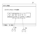
- FIG. 2 shows an example of a login screen displayed on the display unit 16 when the game apparatus 10 is activated.
- the user A who operates the operation unit 15a can log in by selecting an image indicating his / her account “userA”.
- the account “userA” is associated with the operation unit 15a. That is, it is associated that the operator of the operation unit 15a is the user A.
- the operation instruction output from the operation unit 15a is processed as information corresponding to “userA”.
- the user B who operates the operation unit 15b on the same login screen can log in by selecting an image indicating his / her account “userB”, and the account “userB” is associated with the operation unit 15b. That is, it is associated that the operator of the operation unit 15b is the user B.
- the operation instruction output from the operation unit 15b is processed as information corresponding to “userB”. In this way, the game apparatus 10 can specify the operator user from the information specifying the operation unit 15.
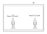
- FIG. 3 is a diagram illustrating an example of a game screen when a plurality of users play a game together using the same game device 10.
- a user A who operates the operation unit 15a and a user B who operates the operation unit 15b play a game together.
- the in-game character Player 1 of the user A and the in-game character Player 2 of the user B are displayed on the screen showing the game content displayed on the display unit 16, and the operation unit operated by the user A Player 1 can be operated from 15a, and Player 2 can be operated from the operation unit 15b operated by the user B.
- game information such as the game progress of each user is recorded in association with each account. That is, various information is managed for each account even if a plurality of users operate at the same time on the same game device 10.
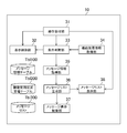
- FIG. 4 is a functional block diagram illustrating an example of functions realized by the game apparatus 10 according to the present embodiment.
- the game device 10 is functionally configured to include an operation receiving unit 31, a display control unit 32, a condition determining unit 33, a function usage information acquiring unit 34, a message information acquiring unit 35, a message list generating unit 36, A message display control unit 37, a message list display unit 38, a message information table Tbl100, a function usage status management table Tbl200, and a message list Tbl300 are configured.
- the operation reception unit 31, the display control unit 32, the function use information acquisition unit 34, the condition determination unit 33, the message information acquisition unit 35, the message display control unit 37, the message list generation unit 36, and the message list display unit. 38 is realized by the control unit 11 executing the program stored in the storage unit 12.
- This program may be provided by being stored in various computer-readable information storage media such as an optical disc, or may be provided via a communication network such as the Internet.
- the message information table Tbl100 and the function usage status management table Tbl200 are realized by the storage unit 12.
- FIG. 5 is a diagram showing an example of the message information table Tbl100 stored in the storage unit 12 of the game apparatus 10. As shown in FIG. As shown in FIG. 5, the message information table Tbl100 is associated with display content X, display content Y, display timing conditions, function use conditions, and a transition destination link after a message instruction operation. This message information table Tbl100 is information common to each user who uses the game apparatus 10.
- the display content X is a message for notifying the user of the functions provided in the game apparatus 10 and is a message reflected in the message image.
- the display content Y is a message for notifying the user of the functions provided in the game apparatus 10 and is a message reflected in the message list image.
- the display content X and the display content Y may be the same content.
- the display timing condition indicates a display timing at which a message image reflecting the display content X is to be displayed. For example, a timing at which a user logs in, a timing at which a home screen is displayed, and a predetermined application is started and ended. Timing, etc. It is assumed that each timing is associated with an operation instruction received by the operation receiving unit 31, and timing information is obtained according to the operation instruction received by the operation receiving unit 31.
- the function usage condition mainly indicates the usage status of the function for displaying the message image, but includes other conditions such as the number of times the predetermined operation has been executed and the timing at which the predetermined operation has been executed. In some cases.
- Each message information is associated with one or more usage conditions as function usage conditions, and it is determined that the function usage conditions are satisfied when all of the associated usage conditions are satisfied.
- the transition destination link indicates a screen that is displayed when the displayed message image is selected by the user, and is a screen on which the function indicated by the display content X or the display content Y can be set. Alternatively, the transition destination link may be a screen for explaining the details of the function indicated by the display content X or the display content Y.
- the function use condition is mainly that the user does not use the function, that is, the function setting is invalidated.
- the display content X and the display content Y are Message 6: “The application can be temporarily suspended during standby”, and the display timing condition is T1. : “When displaying the home screen for the first time after login”, Use condition 6 for the function use condition: “The setting of [Keep application suspended temporarily] is invalid”, Screen 6 for the transition destination link: “Function in standby "Setting screen” is associated.
- the application can remain suspended during standby.
- a message image indicating is displayed.
- a setting screen capable of setting a function during standby is displayed.
- the function that the user is not using is notified, and a screen that enables the setting of the function can be immediately displayed, so that the user can easily use the new function.
- the game apparatus 10 manages the usage status of functions for each of a plurality of users who use the game apparatus 10.
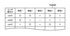
- FIG. 6 is a diagram showing an example of the function usage status management table Tbl200 stored in the storage unit 12 of the game apparatus 10.
- the usage status of functions provided in the game device 10 is managed in the function usage status table for each user identifier indicating a user who uses the game device 10.
- “ ⁇ ” indicates that the function setting is valid
- “ ⁇ ” indicates that the function setting is invalid
- “ ⁇ ” indicates that the function is not permitted to be used.
- count information such as the number of times a predetermined operation has been executed may be managed.
- the function usage status management table Tbl200 all the functions provided in the game apparatus 10 may be managed, but the functions used for each usage condition included in the message information table Tbl100 may be managed.
- the operation reception unit 31 receives a user instruction operation on an operation member provided in the controller.
- the display control unit 32 displays an image corresponding to the instruction operation received by the operation receiving unit 31 on the display unit 16. For example, when the operation receiving unit 31 receives an instruction operation for displaying the home screen, the display control unit 32 displays the home screen of the user who has output the instruction operation on the display unit 16.
- the function usage information acquisition unit 34 acquires function usage information indicating the usage status of various functions corresponding to the user who uses the game apparatus 10 from the function usage status management table Tbl200.
- the condition determination unit 33 Based on the information indicated by the instruction operation received by the operation reception unit 31 and the function usage information acquired by the function usage information acquisition unit 34, the condition determination unit 33 responds to the instruction operation received by the operation reception unit 31. It is determined whether or not to display a message image on the display unit 16. Specifically, the condition determining unit 33 determines whether or not the display timing indicated by the instruction operation received by the operation receiving unit 31 satisfies a predetermined display timing condition. In addition, the condition determination unit 33 determines whether or not a predetermined function usage condition is satisfied from the usage status of each function indicated by the function usage information. The condition determination unit 33 determines whether to display a message image according to whether or not these predetermined timing conditions and predetermined function use conditions are satisfied.
- the message information acquisition unit 35 acquires, from the message information table Tbl100, message information that the condition determination unit 33 determines to satisfy the display timing condition and the function use condition.
- the message list generation unit 36 stores the message information acquired by the message information acquisition unit 35 in the message list Tbl300 in the acquisition order.
- the message information may be stored in the message list Tbl300 in the order stored in the message information table Tbl100.
- the message display control unit 37 displays the message image indicated by the display content X (for message image) included in the message information acquired by the message information acquisition unit 35 on the display unit 16.
- the message image displayed by the message display control unit 37 is displayed superimposed on the image displayed by the display control unit 32. Further, the message display control unit 37 may select any one of the message information stored in the message list Tbl300 and display the message image indicated by the display content included in the message information on the display unit 16.
- the message list display unit 38 displays a message list image indicating the message list Tbl300 on the display unit 16 when the operation receiving unit 31 receives an instruction operation for displaying the message list Tbl300.
- the operation reception unit 31 receives an operation instruction from the operation unit 15a (S101).
- a user identifier of a user who operates the operation unit 15a is included in the operation instruction.
- the condition determining unit 33 determines whether or not the display timing indicated by the operation instruction received by the operation receiving unit 31 satisfies any display timing condition included in the message information table Tbl100 (S102).
- the function usage information acquisition unit 34 is a user included in the operation instruction received by the operation reception unit 31.
- the function usage information corresponding to the identifier is acquired from the function usage status table (S103). For example, when a user identifier (for example, “userA”) indicating the user A is included in the operation instruction received from the operation unit 15a, the function usage information acquisition unit 34 displays the function usage information corresponding to “userA” as the function usage status. Get from table.
- condition determination unit 33 determines whether or not the function usage condition included in the message information table Tbl100 is satisfied from the usage status of each function indicated by the function usage information acquired by the function usage information acquisition unit 34 (S104). ).
- step S104 if it is determined that there is message information that satisfies the function use condition (S104: Y), the message information acquisition unit 35 displays the message information that satisfies the display timing condition and the function use condition in the message information table. Obtained from Tbl 100 (S105). Then, the message list generation unit 36 displays the display content X (for message image), the display content Y (for message list) and the display timing condition included in the message information acquired by the message information acquisition unit 35, and the message information The queue associated with the acquisition date and time is stored to generate the message list Tbl300 (S106).
- FIG. 8 is a diagram showing an example of the message list Tbl300 according to the present embodiment.
- a queue in which the display content X, the display content Y, the display timing condition, and the acquisition date / time among the message information acquired by the message information acquisition unit 35 are associated with each other is stored in the order of acquisition.
- queues with newer acquisition dates are stored below.
- message images are displayed in order from the queue with the oldest acquisition date of message information.
- Each queue is associated with a display flag indicating whether or not a message image is displayed, and a flag (for example, “read”) is displayed in the queue corresponding to the message image displayed by the message display control unit 37. Can be established.
- the message list generation unit 36 may store the plurality of message information in the message list Tbl300 in the order stored in the message information table Tbl100.
- the message information may be stored in the message list Tbl300 in the descending order of priority.
- the message display control unit 37 selects one of the message information acquired by the message information acquisition unit 35 (S107), and a message image indicating the display content X (for message image) included in the selected message information. Is displayed on the display unit 16 (S108). When the message image is displayed on the display unit 16, the message image display process ends.
- the message display control unit 37 determines the display timing condition from the queues included in the message list Tbl300 that do not have the “read” flag.
- the queue that matches the display timing indicated by the operation instruction received by the operation receiving unit 31 and that has the oldest acquisition date is selected, and a message image indicating the display content X (for message image) included in the queue is displayed on the display unit. 16 is displayed.
- a message with the highest priority according to the usage status of the function by the user is presented to the user by selecting and displaying one message information in order of acquisition date and time or priority of the message information. Can do.
- step S104 If it is determined in step S104 that there is no message information that satisfies the function usage condition (S104: N), the condition determination unit 33 sets the “read” flag included in the message list Tbl300. From the queues that have not been set, it is determined whether there is a queue whose display timing condition matches the display timing indicated by the operation instruction received by the operation receiving unit 31 (S109).
- step S109 if it is determined that there is a queue whose display timing condition matches the display timing indicated by the operation instruction received by the operation reception unit 31, the processing after step S107 is executed. As a result of the determination in step S109, when it is determined that there is no queue whose display timing condition matches the display timing indicated by the operation instruction received by the operation reception unit 31, the message image display process ends.
- step S102 if it is determined that none of the display timing conditions included in the message information table Tbl100 is satisfied, the message image display process is terminated.
- FIG. 9 and 10 are diagrams illustrating examples of message images displayed on the display unit 16 according to the present embodiment.
- FIG. 9 shows an example of a message image displayed at the timing when the top screen is displayed in response to a top screen display instruction from the user A.
- the top screen 200A is a screen generated for each user (here, a screen corresponding to the user A), and includes, for example, a function area 201A and a main area 202A.
- a user identification icon 230A indicating a user who performs an operation
- a notification icon 240A indicating that there is a notification to the user
- a function icon 250B indicating a function being used, and the like are displayed.
- an activation image 210A for activating various applications, an application execution history image 220A, and the like are displayed.
- the top screen 200A is displayed by the display control unit 32 when the operation receiving unit 31 receives a top screen display instruction.
- the message image 260A displayed together with such a top screen 200A is displayed superimposed on the top screen 200A, and the display content X (for message image) included in the message information is reflected.
- This message image 260A allows the user to know some of the functions provided in the game apparatus 10. Further, the message image 260A can be selected, and when the user designates the message image 260A, a setting screen for setting the function indicated by the message image 260A is displayed.
- the screen of the transition destination link associated with the message information table Tbl100 is displayed.
- Message image 260A may remain displayed while top screen 200A is displayed, or may be deleted after a predetermined time has elapsed.
- the application can be temporarily suspended during the standby to introduce some of the functions that can be executed during the standby of the game apparatus 10. "Is displayed.
- FIG. 10 shows an example of a message image displayed at the timing when the top screen is displayed according to the top screen display instruction from the user B.
- the configuration of the top screen is the same as that of the top screen of user A shown in FIG. 9, but the display content corresponds to user B.
- the top screen 200B includes, for example, a function area 201B and a main area 202B.
- a user identification icon 230B indicating the user performing the operation
- a notification icon 240B indicating that there is a notification to the user
- a function icon 250B indicating the function being used, and the like are displayed.
- a start image 210B for starting various applications, an execution history image 220B of the application, and the like are displayed.
- the display content of the message image 260 ⁇ / b> B displayed on the top screen 200 ⁇ / b> B of the user B is “can be operated by voice” for introducing a part of the operation function of the game apparatus 10, This is different from the message image 260A displayed on the A top screen 200A.
- the message images displayed on the top screens of the users A and B who use the same game device 10 are in accordance with the usage status of each user's function.
- one message image is displayed on the top screen of each user, it is easy for the user to recognize the message having the highest priority.
- the present embodiment also has a configuration in which all messages to be displayed can be displayed as message list images in accordance with user instructions.
- the message list display unit 38 displays a message list image indicating the message list Tbl300 on the display unit 16 (S202), and the message list.
- the image display process ends.
- FIG. 12 is a diagram illustrating an example of a message list image displayed on the display unit 16 according to the present embodiment.
- a message list image is displayed in the information display area 320 on the notification screen 300 including the notification item area 310 and the information display area 320.
- the notification screen 300 is displayed when the notification icon 240A included in the function area 201A is selected and instructed.
- the operation receiving unit 31 receives an operation instruction for displaying the message list image
- the message list display unit 38 displays a message in the information display area 320. Display list images.
- the entire message list image is actually vertically long or horizontally long, and a part of the display range is displayed in the information display area.
- the display range can be moved by the user performing a predetermined operation such as a scroll operation on the information display area. Thereby, an arbitrary list item 322 included in the message list image can be displayed in the information display area.
- the message list image shown in FIG. 12 is an image in which the message list Tbl300 shown in FIG. 8 is reflected, and information indicating the display content Y (for message list), the acquisition date and time, and the display flag included in the message list Tbl300.
- the displayed list items 322 (322a to 322e in FIG. 12) are displayed in order of acquisition date.
- the list item 322 with a new acquisition date and time is displayed above.
- the list item 322 includes information indicating the display content Y (for message list), the acquisition date and time, and the display flag.
- the present invention is not limited to this example, and the acquisition date and time are displayed if the acquisition order is known. It does not have to be done.
- These list items 322 can be selected by the user, and when the user instructs to select one of the list items 322, a screen of a transition destination link associated with the message information table Tbl100 is displayed.
- FIG. 6 In the state where the notification screen 300 as shown in FIG. 6 is displayed, the processing when one of the list items 322 is instructed by the user will be described.
- the display control unit 32 selects the selected message image 260A, the message image 260B, or the list item 322.
- the transition destination screen indicated by the transition destination link associated with the display content indicated by is displayed on the display unit 16 (S302).
- FIG. 14 is a diagram showing an example of the transition destination screen displayed on the display unit 16 according to the present embodiment.
- FIG. 14 shows a transition destination screen 400 when a message image 260A or a list item 322 with a display content “The application can be temporarily suspended during standby” is instructed.
- a setting screen for setting a function in the standby mode is displayed as the transition destination screen 400.
- a message for informing the function is displayed on the top screen 200A.
- a setting screen that can be set as a function of “keep the application suspended during standby mode” is displayed as the transition destination screen 400 to prompt the user to set the function.
- a setting screen capable of setting the function indicated by the display content of the message image 260A or the list item 322 is displayed as the transition destination screen 400, but is not limited to this example.
- a screen that displays a detailed description of the function indicated by the display content of the message image 260A or the list item 322 or a screen that describes a display method of a setting screen for setting the function is displayed as the transition destination screen 400. May be.
- One of the functions provided in the game apparatus 10 is a power supply function. Turning on / off the power is a function that is always used when using the game apparatus 10, and it is desirable that information that is particularly suitable for each user can be presented for such frequently used functions. Therefore, on the power operation screen for using the power function, information suitable for the user is presented according to the usage status of each user's function. This will be described in detail below.
- the power operation screen 500 includes a plurality of operation image items 510 (510a, 510b, 510c).
- the operation image item 510a is an item for selecting the power supply function A, and the power supply function A is executed when the operation image item 501a is selected and operated.
- the image indicating the power supply function A displayed in the operation image item 510a is unchanged. For example, an image indicating the power supply function such as “log out” or “switch user” is always displayed. That is, the user may display the power operation screen in order to execute the power function A.
- the operation image item 510b is an item for selecting the power supply function B.
- the power supply function B is executed.
- the image indicating the power supply function B displayed in the operation image item 510b is switched according to the usage status of the specific function, and among the images indicating the power supply functions of a plurality of display candidates, the image is displayed according to the specific usage status of the function. Either one is displayed.
- an image showing the power supply function of “put in standby mode” and an image showing the power supply function of “turn off power” are switched and displayed according to the usage status of a specific function.
- FIG. 15A shows a power operation screen on which an image indicating the power function “set to standby mode” is displayed in the operation image item 510b.
- FIG. 15B shows a power operation screen on which an image indicating the power function “turn off” is displayed in the operation image item 510b.
- the operation screen item 510c is an item for selecting a power supply option.
- the power option indicates other power functions that are not displayed in the operation image item 510a and the operation image item 510b, and a power option operation screen for selecting another power function when the operation screen item 510c is selected and operated. Is displayed.
- FIG. 16 is a diagram illustrating an example of a power option operation screen displayed on the display unit 16 according to the present embodiment.
- the power option operation screen 540 shown in FIG. 16 is displayed when the operation image item 510c shown in FIGS. 15A and 15B is selected and operated.
- the power option operation screen 540 according to the present embodiment includes a plurality of operation image items 550 (550a, 550b).
- an image indicating the power supply function B of all display candidates that can be displayed in the operation image item 510b illustrated in FIGS. 15A and 15B is displayed.
- this operation image item 550a it is possible to select execution of another power function B that is not displayed in the operation image item 510b of the power operation screen 500.
- an image showing the power function B of “put to standby mode” which is an image showing the power function B of a display candidate that can be displayed in the operation image item 510 b in FIGS. 15A and 15B.
- an image indicating the power supply function of “turn off power” is displayed in the operation image item 550a.
- FIG. 16 shows an example in which an image showing the power functions B of all display candidates that can be displayed in the operation image item 510b is displayed in the operation image item 550a.
- Only an image indicating a power supply function that is not displayed in the operation image item 510b may be displayed.
- an image indicating another power function that is not displayed on the power operation screen 500 illustrated in FIGS. 15A and 15B is displayed.
- an image indicating the power function of “restart” is displayed.
- the power function frequently used by the user can be selected and executed on the power operation screen 500, and the power function used only occasionally is selected and executed on the power option operation screen, so that the user often uses it. It becomes easy to execute the power supply function.
- an image showing a plurality of display candidate power supply functions B that can be displayed in the operation image item 510b is switched in accordance with the usage status of a specific function.
- an image showing the power function B of the display candidate which is an image showing the power function of “put in standby mode”, and an image showing the power function of “turn off power” are switched.
- the display of the images showing these two power supply functions is switched according to the usage status of the “function in the standby mode”.
- the operation image item 510 b is set to “set to standby mode”.
- An image showing the power supply function is displayed.
- the operation image item 510 b shows the power function “turn off”. Is displayed.
- the image displayed in the operation image item 510b is switched as described above according to the usage status of the function in the standby mode. This makes it possible to present to the user a power operation screen suitable for the usage status of the function by the user, and it is easy for the user to execute a frequently used power function.
- the function usage information acquiring unit 34 displays the function usage information corresponding to the user identifier included in the operation instruction in the function usage state management table. Obtained from Tbl 200 (S402).
- the function usage information acquisition unit 34 acquires information on “functions in standby mode” from the function usage status management table Tbl200 as function usage information.
- condition determination unit 33 determines whether at least one of the setting items included in the “function in standby mode” is valid (S403).
- step S403 if it is determined that at least one setting item among the setting items included in “function in standby mode” is valid (S403: Y), the display control unit 32 As shown in FIG. 15A, an image indicating the power function “set to standby mode” is displayed in the operation image item 510b of the power operation screen (S404). On the other hand, as a result of the determination in step S403, when it is determined that all the setting items included in the “function in standby mode” are invalid (S403: N), the display control unit 32 displays the settings in FIG. 15B. As shown in the figure, an image indicating the power-off function of “turn off power” is displayed in the operation image item 510b of the power supply unit operation screen.
- the game apparatus 10 capable of displaying the power operation screen as described above, it is particularly effective to display a message image related to the power operation screen display processing according to the use status of the user's power function. Specifically, when a user who has enabled at least one setting item included in the function in the standby mode selects and executes the “power off” power function from the operation image item 550a on the power option operation screen. Displays a message image with the content “Easy access to frequently used power options” and disables all setting items included in the function in standby mode on the transition destination screen. It is assumed that an image indicating the power supply function of “OFF” is displayed. Accordingly, it is possible to notify the user who has made the setting of the function in the standby mode valid even when not necessary, or the user who does not know about the power operation screen display processing at the appropriate timing.
- a user who has enabled at least one setting item included in the function in the standby mode selects and executes the “power off” power function from the operation image item 550a on the power option operation screen.
- Message images may be displayed.
- a user who frequently selects and executes the “power off” power function from the operation image item 550a on the power option operation screen does not need the function setting in the standby mode to be effective.
- a user who has a low frequency of selecting and executing the “power off” power function from the operation image item 550a on the power option operation screen is usually executing the standby mode. The power may have been turned off.
- a message image is displayed to a user who frequently executes the operation by selecting the “power off” power function from the operation image item 550a on the power option operation screen, and the power image is displayed from the operation image item 550a on the power option operation screen. If a message image is not displayed to a user who does not frequently execute the power function by selecting the “OFF” power supply function, a message image that informs the user of the appropriate power function according to the usage status of the function is presented. Is possible.
Landscapes
- Engineering & Computer Science (AREA)
- Multimedia (AREA)
- Business, Economics & Management (AREA)
- Computer Security & Cryptography (AREA)
- General Business, Economics & Management (AREA)
- Physics & Mathematics (AREA)
- Optics & Photonics (AREA)
- User Interface Of Digital Computer (AREA)
Abstract
ゲーム装置に備えられる機能の使用状況に応じてユーザに適した機能の使用を促進するゲーム装置を提供する。 ユーザによるゲーム装置に備えられる機能の使用状況を管理する機能使用状況管理テーブル(Tbl200)と、ユーザによる所与の指示に対応付けて記憶されている前記機能に関する複数のメッセージそれぞれについて当該所与の指示に応じて表示すべきか否かを、当該ユーザの前記機能の使用状況に応じて判断する条件判断部(33)と、ユーザによる所与の指示に応じて表示すべきと判断された複数のメッセージのうち、いずれか1つを表示するメッセージ表示制御部(37)と、を含む。
Description
本発明は、ゲーム装置、ゲーム装置の制御方法、及びプログラムに関する。
アップデートにより追加された機能に関する情報を更新情報として提示するゲーム装置は知られている。
ゲーム装置には各種の機能が備えられており、ゲーム装置を利用するユーザによって機能の使用状況は異なる。したがって、追加された機能に関する情報を提示するだけでは、ユーザによっては不必要な情報が含まれたり、既に使用している機能に関する情報が含まれたりしてユーザに適した情報が提示されるとは限らない。
本発明は上記実情を考慮してなされたものであって、その目的の一つは、ゲーム装置に備えられる機能の使用状況に応じてユーザに適した機能の使用を促進するゲーム装置を提供することにある。
さらに、本発明の目的の一つは、ゲーム装置においてよく使用される機能の一つである電源機能について、ユーザによる機能の使用状況に応じた使いやすい電源機能を提供することにある。
上記課題を解決するために、本発明に係るゲーム装置は、ユーザによるゲーム装置に備えられる機能の使用状況を管理する管理手段と、前記ユーザによる所与の指示に対応付けて記憶されている前記機能に関する複数のメッセージそれぞれについて当該所与の指示に応じて表示すべきか否かを、当該ユーザの前記機能の使用状況に応じて判断する判断手段と、前記ユーザによる所与の指示に応じて表示すべきと判断された複数の前記メッセージのうち、いずれか1つを表示するメッセージ表示制御手段と、を含むことを特徴とする。
また、上記ゲーム装置において、前記判断部が前記所与の指示に対応付けられて記憶されている前記機能を使用していないと判断した場合に、前記メッセージ表示制御手段は、前記ユーザによる前記所与の指示に応じて当該機能に関するメッセージを表示する、こととしてもよい。
また、上記ゲーム装置において、前記メッセージ表示制御手段は、前記ユーザによる所与の指示に応じて表示すべきと判断された複数の前記メッセージのうち表示されなかったメッセージのいずれか1つを、次の前記ユーザによる所与の指示に応じて表示する、こととしてもよい。
また、上記ゲーム装置において、前記判断部により前記ユーザによる所与の指示に応じて表示すべきと判断された複数の前記メッセージを格納したメッセージリストを生成するメッセージリスト生成手段と、前記ユーザによる指示にしたがって前記メッセージリストを示すメッセージリスト画像を表示するメッセージリスト表示手段と、をさらに含む、こととしてもよい。
また、上記ゲーム装置において、前記メッセージリスト生成手段は、前記判断手段が前記ユーザによる所与の指示に応じて表示すべきと判断した順に前記メッセージを格納する、こととしてもよい。
また、上記ゲーム装置において、前記表示されたメッセージが前記ユーザにより選択指示されることで、当該メッセージが示す機能に関する情報が示される遷移画面を表示する遷移画面表示制御手段、をさらに含む、こととしてもよい。
また、上記ゲーム装置において、前記管理手段は、前記ゲーム装置を使用する複数のユーザそれぞれについて前記ゲーム装置に備えられる機能の使用状況を管理し、前記判断手段は、前記ユーザによる所与の指示に対応付けて記憶されている前記機能に関するメッセージを当該所与の指示に応じて表示するか否かを、当該ユーザに対応する前記機能の使用状況に応じて判断する、こととしてもよい。
上記課題を解決するために、本発明に係るゲーム装置は、電源をスタンバイ状態または切状態にするための操作画像を含む電源操作画面を表示する電源操作画面表示手段と、前記電源がスタンバイ状態において使用可能な機能の設定状況を示す情報を取得する取得手段と、を含み、前記スタンバイ状態において使用可能な機能の設定状況に応じて、前記電源操作画面表示手段は、前記電源をスタンバイ状態にする前記操作画像、または、前記電源を切状態にする前記操作画像、を前記電源操作画面に含める、ことを特徴とする。
また、本発明に係るゲーム装置の制御方法は、電源をスタンバイ状態または切状態にするための操作画像を含む電源操作画面を表示する電源操作画面表示手段、前記電源がスタンバイ状態において使用可能な機能の設定状況を示す情報を取得する取得手段、を含み、前記スタンバイ状態において使用可能な機能の設定状況に応じて、前記電源操作画面表示手段は、前記電源をスタンバイ状態にする前記操作画像、または、前記電源を切状態にする前記操作画像、を前記電源操作画面に含める、ことを特徴とする。
また、本発明に係るプログラムは、電源をスタンバイ状態または切状態にするための操作画像を含む電源操作画面を表示する電源操作画面表示手段、前記電源がスタンバイ状態において使用可能な機能の設定状況を示す情報を取得する取得手段、としてゲーム装置を機能させるためのプログラムであって、前記スタンバイ状態において使用可能な機能の設定状況に応じて、前記電源操作画面表示手段は、前記電源をスタンバイ状態にする前記操作画像、または、前記電源を切状態にする前記操作画像、を前記電源操作画面に含める、ことを特徴とする。このプログラムは、コンピュータ読み取り可能な情報記憶媒体に格納されてよい。
また、本発明に係るゲーム装置の制御方法は、ユーザによるゲーム装置に備えられる機能の使用状況を管理する管理手段と、前記ユーザによる所与の指示に対応付けて記憶されている前記機能に関する複数のメッセージそれぞれについて当該所与の指示に応じて表示すべきか否かを、当該ユーザの前記機能の使用状況に応じて判断する判断手段と、前記ユーザによる所与の指示に応じて表示すべきと判断された複数の前記メッセージのうち、いずれか1つを表示するメッセージ表示制御手段と、を含むことを特徴とする。
また、本発明に係るプログラムは、ユーザによるゲーム装置に備えられる機能の使用状況を管理する管理手段、前記ユーザによる所与の指示に対応付けて記憶されている前記機能に関する複数のメッセージそれぞれについて当該所与の指示に応じて表示すべきか否かを、当該ユーザの前記機能の使用状況に応じて判断する判断手段、前記ユーザによる所与の指示に応じて表示すべきと判断された複数の前記メッセージのうち、いずれか1つを表示するメッセージ表示制御手段、としてゲーム装置を機能させる。このプログラムは、コンピュータ読み取り可能な情報記憶媒体に格納されてよい。
以下、本発明の実施の形態について、図面に基づき詳細に説明する。
[メッセージ表示処理]
図1は、本実施形態に係るゲーム装置10の全体構成の一例を示す構成ブロック図である。ゲーム装置10は、ユーザがゲームをプレイしたり、動画像を視聴したりするために用いる情報処理装置であって、家庭用ゲーム機や携帯型ゲーム機、パーソナルコンピュータ等であってよい。図1に示すように、本実施形態に係るゲーム装置10は、制御部11、記憶部12、画像処理部13、及び通信部14、及びを含んで構成される。また、ゲーム装置10は、操作部15a、操作部15b及び表示部16と接続される。
図1は、本実施形態に係るゲーム装置10の全体構成の一例を示す構成ブロック図である。ゲーム装置10は、ユーザがゲームをプレイしたり、動画像を視聴したりするために用いる情報処理装置であって、家庭用ゲーム機や携帯型ゲーム機、パーソナルコンピュータ等であってよい。図1に示すように、本実施形態に係るゲーム装置10は、制御部11、記憶部12、画像処理部13、及び通信部14、及びを含んで構成される。また、ゲーム装置10は、操作部15a、操作部15b及び表示部16と接続される。
制御部11は、CPU等のプログラム制御デバイスを含み、記憶部12に記憶されたプログラムに従って各種の情報処理を実行する。記憶部12は、RAMやROM等のメモリ素子を含んで構成され、制御部11が実行するプログラムや、このプログラムによる処理の対象となるデータを記憶する。また、記憶部12は制御部11のワークメモリとしても機能する。
画像処理部13は、例えばGPUとフレームバッファメモリとを含んで構成され、制御部11が出力する描画指示に従って、表示部16の画面に表示する画像を描画する。具体例として、画像処理部13は表示部16の画面に対応したフレームバッファメモリを備え、GPUは、制御部11からの指示に従って、所定時間おきにこのフレームバッファメモリに対して画像を書き込む。そして、このフレームバッファメモリに書き込まれた画像が、所定のタイミングでビデオ信号に変換されて、表示部16の画面に表示される。
通信部14は、通信ネットワークを介して他の装置との間でデータを授受するためのインタフェースであって、ゲーム装置10は、通信部14を介して他の装置との間で情報の送受信を行う。
操作部15a及び15bは、ユーザの操作入力を受け付けるデバイスであって、例えばキーボードやマウス、家庭用ゲーム機のコントローラなどであってよい。また、操作部15a及び15bは、ゲーム装置10の筐体表面に備えられる操作ボタンやスイッチ等の操作部材を含んでもよい。ユーザは、操作部15aまたは操作部15bに対して操作を行うことで、ゲーム装置10に対して各種の指示を入力する。
表示部16は、家庭用テレビ受像機や液晶ディスプレイなどの表示装置であって、画像処理部13が出力するビデオ信号に応じた画像を表示する。
本実施形態では、ゲーム装置10は、各種の機能を備えており、ユーザが選択、設定をすることで任意の機能を使用することができる。具体的には、ゲーム装置10には、“音声操作”、“フレンドとのシェアプレイ”、“スタンバイモード中に自動でシステムソフトウェアをアップデートできる”、“アプリケーションを一時中断したままスタンバイモードにできる”などの機能が備えられている。これらの機能は、ユーザが機能の設定を有効にすることで使用可能となるため、ユーザによっては使用したことがない機能や、存在すら知らない機能があることが考えられる。そこで、本実施形態では、ユーザによる機能の使用状況に応じてユーザに適した機能の存在を知らせるメッセージを表示する。これにより、ユーザが使用したことがない機能や、存在を知らなかった機能の利用の促進を図る。
また、本実施形態では、複数のユーザが同じゲーム装置10を利用する。各ユーザはそれぞれ個別のアカウントを作成してログインすることでゲーム装置10を利用することができる。図2は、本実施形態に係る複数のユーザにより利用されるゲーム装置10の利用状況の一例を示す図である。図2は、ゲーム装置10を起動したときに表示部16に表示されるログイン画面の一例を示す。このようなログイン画面において、操作部15aを操作するユーザAが自身のアカウント“userA”を示す画像を選択することでログインでき、このとき操作部15aにアカウント“userA”が対応付けられる。つまり、操作部15aの操作者がユーザAであると対応付けられる。以後、操作部15aから出力される操作指示は“userA”に対応する情報として処理される。また、同じログイン画面において操作部15bを操作するユーザBが自身のアカウント“userB”を示す画像を選択することでログインでき、操作部15bにアカウント“userB”が対応付けられる。つまり、操作部15bの操作者がユーザBであると対応付けられる。以後、操作部15bから出力される操作指示は“userB”に対応する情報として処理される。このようにして、ゲーム装置10は、操作部15を特定する情報から、操作者のユーザを特定することができる。
そして、本実施形態では、複数のユーザそれぞれが各自のアカウントにログインしている状態で一緒にゲームをプレイすることができる。図3は、複数のユーザが同じゲーム装置10を用いて一緒にゲームプレイする際のゲーム画面の一例を示す図である。ここでは、操作部15aを操作するユーザAと、操作部15bを操作するユーザBと、が一緒にゲームをプレイしている。図3に例示するように、表示部16に表示されたゲーム内容を示す画面に、ユーザAのゲーム内キャラククターPlayer1とユーザBのゲーム内キャラクタPlayer2とが表示され、ユーザAが操作する操作部15aからPlayer1が操作可能であり、ユーザBが操作する操作部15bからPlayer2が操作可能となっている。このとき、各ユーザのゲーム進行状況などのゲーム情報は、それぞれのアカウントに対応付けて記録される。つまり、同じゲーム装置10において複数のユーザそれぞれが同時に操作してもアカウント毎に各種情報が管理されるようになっている。
同様にして、ゲーム装置10に備えられる各機能の設定もユーザ毎、アカウント毎に管理されるため、各ユーザにおいてゲーム装置10に備えられる機能の使用状況は異なることとなる。そこで、複数のユーザが利用するゲーム装置10において、各ユーザの機能の使用状況に応じて各ユーザに適した機能に関する情報を提示できるようにする。
以下、本実施形態においてゲーム装置10が実現する機能について、説明する。図4は、本実施形態に係るゲーム装置10が実現する機能の一例を示す機能ブロック図である。図4に示すように、ゲーム装置10は、機能的に、操作受付部31、表示制御部32、条件判断部33、機能使用情報取得部34、メッセージ情報取得部35、メッセージリスト生成部36、メッセージ表示制御部37、メッセージリスト表示部38、メッセージ情報テーブルTbl100、機能使用状況管理テーブルTbl200、及びメッセージリストTbl300を含んで構成される。これらの機能のうち、操作受付部31、表示制御部32、機能使用情報取得部34、条件判断部33、メッセージ情報取得部35、メッセージ表示制御部37、メッセージリスト生成部36、メッセージリスト表示部38は、記憶部12に記憶されたプログラムを制御部11が実行することで実現される。このプログラムは、例えば光ディスク等のコンピュータ読み取り可能な各種の情報記憶媒体に格納されて提供されてもよいし、インターネット等の通信ネットワークを介して提供されてもよい。また、メッセージ情報テーブルTbl100、機能使用状況管理テーブルTbl200は、記憶部12によって実現される。
本実施形態においては、表示され得るメッセージの情報が予め記憶部12に記憶されていることとする。図5は、ゲーム装置10の記憶部12に記憶されているメッセージ情報テーブルTbl100の一例を示す図である。図5に示すように、メッセージ情報テーブルTbl100には、表示内容X、表示内容Y、表示タイミング条件、機能使用条件、及びメッセージ指示操作後の遷移先リンクが関連付けられている。このメッセージ情報テーブルTbl100はゲーム装置10を利用する各ユーザに共通の情報である。表示内容Xは、ゲーム装置10に備えられる機能をユーザに知らせるためのメッセージであり、メッセージ画像に反映されるメッセージである。表示内容Yは、ゲーム装置10に備えられる機能をユーザに知らせるためのメッセージであり、メッセージリスト画像に反映されるメッセージである。なお、表示内容Xと表示内容Yとは同じ内容であってもよい。表示タイミング条件は、表示内容Xが反映されたメッセージ画像が表示されるべき表示タイミングを示すものであり、例えばユーザがログインするタイミング、ホーム画面を表示するタイミング、所定のアプリケーションの起動、終了を行うタイミング、などである。各タイミングは、操作受付部31が受け付ける操作指示に対応づけられていることとし、操作受付部31が受け付けた操作指示に応じてタイミングの情報が得られる。機能使用条件は主に、メッセージ画像が表示されるための機能の使用状況を示すものとするが、他には所定の操作を実行した回数や所定の操作を実行したタイミングなどの条件が含まれる場合もある。各メッセージ情報には機能使用条件として1以上の使用条件が関連付けられており、関連付けられている使用条件をすべて満たす場合に機能使用条件を満たすと判断される。遷移先リンクは、表示されたメッセージ画像がユーザにより選択指示された場合に表示される画面を示すものであり、表示内容Xまたは表示内容Yが示す機能の設定が可能な画面となる。または、遷移先リンクは、表示内容Xまたは表示内容Yが示す機能の詳細を説明する画面であってもよい。
本実施形態において、メッセージ画像として表示される表示内容は、ユーザに対して機能の使用を促進するものであるので、ユーザが使用していない、知らない機能を知らせることが有効である。したがって、機能使用条件としては、主にユーザが機能を使用していない、つまりは機能の設定を無効としていることが条件となる。具体的には、例えば、メッセージ情報テーブルTbl100に含まれるメッセージ情報M6には、表示内容X及び表示内容YにMessage6:“スタンバイ中にアプリケーションを一時中断したままにできます”、表示タイミング条件にT1:“ログイン後初めてのホーム画面表示時”、機能使用条件に使用条件6:“[アプリケーションを一時中断したままにする]の設定が無効”、遷移先リンクに画面6:“スタンバイ中の機能の設定画面”が関連付けられている。このとき、ユーザがログインしてホーム画面を表示したタイミングで、[アプリケーションを一時中断したままにする]の設定が無効となっていると、“スタンバイ中にアプリケーションを一時中断したままにできます”を示すメッセージ画像が表示されることとなる。そして、当該メッセージ画像がユーザにより選択指示されることで、スタンバイ中の機能の設定が可能な設定画面が表示される。このように、ユーザが使用していない機能について知らせるとともに、当該機能の設定を有効にすることができる画面をすぐに提示できるようにしていることで、ユーザにとって新しい機能を使いやすくなる。
また、本実施形態においては、ゲーム装置10は、ゲーム装置10を利用する複数のユーザそれぞれについて機能の使用状況を管理していることとする。図6は、ゲーム装置10の記憶部12に記憶される機能使用状況管理テーブルTbl200の一例を示す図である。図6に示すように、機能使用状況テーブルには、ゲーム装置10を利用するユーザを示すユーザ識別子毎に、ゲーム装置10に備えられる機能の使用状況が管理されている。ここでは、機能の設定が有効となっている場合を“○”、機能の設定が無効となっている場合を“×”、機能の使用許可がない場合を“-”で示している。また、機能の設定の有効/無効だけでなく、所定の操作を実行した回数などのカウント情報が管理されていてもよい。また、機能使用状況管理テーブルTbl200において、ゲーム装置10に備えられる機能がすべて管理されてもよいが、メッセージ情報テーブルTbl100に含まれる各使用条件に用いられる機能が管理されていてもよい。
操作受付部31は、コントローラに備えられる操作部材に対するユーザの指示操作を受け付ける。
表示制御部32は、操作受付部31が受け付けた指示操作に応じた画像を表示部16に表示する。例えば、操作受付部31がホーム画面を表示するための指示操作を受け付けた場合は、表示制御部32は、指示操作を出力したユーザのホーム画面を表示部16に表示する。
機能使用情報取得部34は、ゲーム装置10を利用するユーザに対応する各種機能の使用状況を示す機能使用情報を機能使用状況管理テーブルTbl200から取得する。
条件判断部33は、操作受付部31が受け付けた指示操作が示す情報と、機能使用情報取得部34が取得した機能使用情報と、に基づいて、操作受付部31が受け付けた指示操作に応じて表示部16にメッセージ画像を表示するか否かを判断する。具体的には、条件判断部33は、操作受付部31が受け付けた指示操作が示す表示タイミングが所定の表示タイミング条件を満たすか否かを判断する。また、条件判断部33は、機能使用情報が示す各機能の使用状況から所定の機能使用条件を満たすか否かを判断する。条件判断部33は、これら所定のタイミング条件及び所定の機能使用条件を満たすか否かに応じて、メッセージ画像を表示するか否かを判断している。
メッセージ情報取得部35は、条件判断部33が表示タイミング条件及び機能使用条件を満たすと判断したメッセージ情報をメッセージ情報テーブルTbl100から取得する。
メッセージリスト生成部36は、メッセージ情報取得部35が取得したメッセージ情報を、取得順にメッセージリストTbl300に格納する。なお、メッセージ情報取得部35が一度に取得するメッセージ情報が複数ある場合には、メッセージ情報テーブルTbl100に格納されている順にメッセージリストTbl300に格納すればよい。
メッセージ表示制御部37は、メッセージ情報取得部35が取得したメッセージ情報に含まれる表示内容X(メッセージ画像用)が示すメッセージ画像を表示部16に表示する。メッセージ表示制御部37が表示するメッセージ画像は、表示制御部32が表示する画像に重畳して表示される。また、メッセージ表示制御部37は、メッセージリストTbl300に格納されたメッセージ情報からいずれかを選択し、当該メッセージ情報に含まれる表示内容が示すメッセージ画像を表示部16に表示してもよい。
メッセージリスト表示部38は、操作受付部31がメッセージリストTbl300を表示するための指示操作を受け付けた場合に、メッセージリストTbl300を示すメッセージリスト画像を表示部16に表示する。
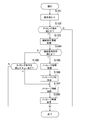
ここで、本実施形態に係るゲーム装置10が実行するメッセージ画像表示処理について図7のフロー図を参照して説明する。
まず、操作受付部31は、操作部15aから操作指示を受け付ける(S101)。ここでは、操作指示に操作部15aを操作するユーザのユーザ識別子が含まれることとする。そして、条件判断部33が、操作受付部31が受け付けた操作指示が示す表示タイミングが、メッセージ情報テーブルTbl100に含まれるいずれかの表示タイミング条件を満たすか否かを判断する(S102)。
処理S102の判断の結果、メッセージ情報テーブルTbl100に含まれるいずれかの表示タイミング条件を満たすと判断された場合は、機能使用情報取得部34が、操作受付部31が受け付けた操作指示に含まれるユーザ識別子に対応する機能使用情報を機能使用状況テーブルから取得する(S103)。例えば、操作部15aから受け付ける操作指示にユーザAを示すユーザ識別子(例えば、“userA”)が含まれる場合は、機能使用情報取得部34は、“userA”に対応する機能使用情報を機能使用状況テーブルから取得する。
次に、条件判断部33は、機能使用情報取得部34が取得した機能使用情報が示す各機能の使用状況から、メッセージ情報テーブルTbl100に含まれる機能使用条件を満たすか否かを判断する(S104)。
処理S104の判断の結果、機能使用条件を満たすメッセージ情報があると判断された場合は(S104:Y)、メッセージ情報取得部35が、表示タイミング条件及び機能使用条件を満たすメッセージ情報をメッセージ情報テーブルTbl100から取得する(S105)。そして、メッセージリスト生成部36が、メッセージ情報取得部35が取得したメッセージ情報に含まれる表示内容X(メッセージ画像用)、表示内容Y(メッセージリスト用)、及び表示タイミング条件と、当該メッセージ情報の取得日時とを関連付けたキューを格納してメッセージリストTbl300を生成する(S106)。
図8は、本実施形態に係るメッセージリストTbl300の一例を示す図である。図8に示すように、メッセージ情報取得部35が取得したメッセージ情報のうち表示内容X、表示内容Y、及び表示タイミング条件と、その取得日時とが関連付けられたキューが取得順に格納される。すなわち、取得日時が新しいキューほど下に格納されている。基本的には、メッセージ情報の取得日時が古いキューから順にメッセージ画像が表示されることとなる。また、各キューには、メッセージ画像が表示されたか否かを示す表示フラグが関連付けられており、メッセージ表示制御部37が表示したメッセージ画像に対応するキューにフラグ(例えば、“既読”)がたてられる。なお、同じタイミングで取得されるメッセージ情報が複数ある場合は、メッセージリスト生成部36は、複数のメッセージ情報をメッセージ情報テーブルTbl100に格納されている順にメッセージリストTbl300に格納してもよいし、複数のメッセージ情報に優先度を関連付けて優先度の高い順にメッセージリストTbl300に格納してもよい。
そして、メッセージ表示制御部37が、メッセージ情報取得部35が取得したメッセージ情報から1つを選択し(S107)、当該選択されたメッセージ情報に含まれる表示内容X(メッセージ画像用)を示すメッセージ画像を表示部16に表示する(S108)。表示部16にメッセージ画像が表示されるとメッセージ画像表示処理は終了する。ここで、メッセージリストTbl300にすでにキューが格納されている場合は、メッセージ表示制御部37は、メッセージリストTbl300に含まれる“既読”フラグがたてられていないキューのなかから、その表示タイミング条件が、操作受付部31が受け付けた操作指示が示す表示タイミングと一致し、かつ取得日時が最も古いキューを選択し、当該キューに含まれる表示内容X(メッセージ画像用)を示すメッセージ画像を表示部16に表示する。このように、取得日時順や、メッセージ情報の優先度順に1つのメッセージ情報が選択されて表示されることで、ユーザによる機能の使用状況に応じた優先度の最も高いメッセージをユーザに提示することができる。
また、処理S104の判断の結果、機能使用条件を満たすメッセージ情報がないと判断された場合は(S104:N)、条件判断部33は、メッセージリストTbl300に含まれる“既読”フラグがたてられていないキューのなかから、その表示タイミング条件が、操作受付部31が受け付けた操作指示が示す表示タイミングと一致するキューが存在するか判断する(S109)。
処理S109の判断の結果、その表示タイミング条件が、操作受付部31が受け付けた操作指示が示す表示タイミングと一致するキューが存在すると判断された場合は、処理S107以降の処理を実行する。そして、処理S109の判断の結果、その表示タイミング条件が、操作受付部31が受け付けた操作指示が示す表示タイミングと一致するキューが存在しないと判断された場合は、メッセージ画像表示処理を終了する。
また、処理S102の判断の結果、メッセージ情報テーブルTbl100に含まれるいずれの表示タイミング条件も満たさないと判断された場合は、メッセージ画像表示処理を終了する。
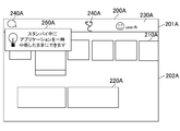
図9及び図10は、本実施形態に係る表示部16に表示されるメッセージ画像の一例を示す図である。図9は、ユーザAからのトップ画面表示指示に応じてトップ画面が表示されるタイミングで表示されるメッセージ画像の例を示している。トップ画面200Aは、ユーザ毎に生成される画面(ここでは、ユーザAに対応する画面)であり、例えばファンクション領域201Aと、メイン領域202Aとを含んで構成される。ファンクション領域201Aには、操作を行うユーザを示すユーザ識別アイコン230A、ユーザに対するお知らせがあることを示すお知らせアイコン240A、使用している機能を示す機能アイコン250Bなどが表示される。メイン領域202Aには、各種アプリケーションを起動するための起動画像210A、アプリケーションの実行履歴画像220Aなどが表示される。トップ画面200Aは、操作受付部31がトップ画面表示指示を受け付けることにより表示制御部32が表示するものである。このようなトップ画面200Aとともに表示されるメッセージ画像260Aは、トップ画面200Aに重畳して表示され、メッセージ情報に含まれる表示内容X(メッセージ画像用)が反映されている。このメッセージ画像260Aによりユーザは、ゲーム装置10に備えられる機能の一部を知ることができる。また、メッセージ画像260Aは選択指示可能となっており、ユーザによりメッセージ画像260Aが選択指示されることで、メッセージ画像260Aで示している機能を設定するための設定画面が表示される。ここでは、メッセージ情報テーブルTbl100に関連付けられている遷移先リンクの画面が表示されることとする。これにより、ユーザがメッセージ画像260Aを見て機能を使用したいと思った場合に、ユーザが設定画面を探す手間を省くことができる。なお、メッセージ画像260Aは、トップ画面200Aが表示されている間は表示されたままとしてもよいし、所定時間経過後に消去されることとしてもよい。例えば、ユーザAのトップ画面200Aに表示されるメッセージ画像260Aには、ゲーム装置10のスタンバイ中に実行可能な機能の一部を紹介するための“スタンバイ中にアプリケーションを一時中断したままにできます”が表示される。
一方で、図10は、ユーザBからのトップ画面表示指示に応じてトップ画面が表示されるタイミングで表示されるメッセージ画像の例を示している。トップ画面の構成は図9に示したユーザAのトップ画面と同様であるが表示内容はユーザBに対応したものとなる。トップ画面200Bは、例えばファンクション領域201Bと、メイン領域202Bとを含んで構成される。ファンクション領域201Bには、操作を行うユーザを示すユーザ識別アイコン230B、ユーザに対するお知らせがあることを示すお知らせアイコン240B、使用している機能を示す機能アイコン250Bなどが表示される。メイン領域202Bには、各種アプリケーションを起動するための起動画像210B、アプリケーションの実行履歴画像220Bなどが表示される。図10に示すように、ユーザBのトップ画面200Bに表示されるメッセージ画像260Bの表示内容は、ゲーム装置10の操作機能の一部を紹介するための“声で操作できます”であり、ユーザAのトップ画面200Aに表示されるメッセージ画像260Aとは異なる。
図9及び図10に示すように、同じゲーム装置10を用いるユーザA及びユーザBそれぞれのトップ画面に表示されるメッセージ画像は、各ユーザの機能の使用状況に応じたものとなる。また、各ユーザのトップ画面に表示されるメッセージ画像を1つとすることで、ユーザにとって優先度の最も高いメッセージを認識しやすくしている。一方で、ユーザによっては表示されるべきメッセージをすべて確認したいという事情がある。そこで、本実施形態では、表示されるべきすべてのメッセージをメッセージリスト画像としてユーザの指示に応じて表示できる構成も有している。
次に、本実施形態に係るゲーム装置10が実行するメッセージリスト画像表示処理について図11のフロー図を参照して説明する。
操作受付部31がメッセージリスト画像を表示するための操作指示を受け付けると(S201)、メッセージリスト表示部38がメッセージリストTbl300を示すメッセージリスト画像を表示部16に表示して(S202)、メッセージリスト画像表示処理を終了する。
図12は、本実施形態に係る表示部16に表示されるメッセージリスト画像の一例を示す図である。図12に示すように、お知らせ項目領域310と情報表示領域320とを含むお知らせ画面300において、情報表示領域320にメッセージリスト画像が表示される。なお、図9に示したトップ画面200Aにおいて、ファンクション領域201Aに含まれるお知らせアイコン240Aが選択指示されることで、お知らせ画面300が表示される。さらに、お知らせ項目領域310に含まれるメッセージ項目312が選択指示されることで、操作受付部31がメッセージリスト画像を表示するための操作指示を受け付け、メッセージリスト表示部38が情報表示領域320にメッセージリスト画像を表示する。メッセージリスト画像全体は、実際は縦長形状、または横長形状となっており、情報表示領域にはその一部の表示範囲が表示されている。そして、情報表示領域に対してユーザがスクロール操作などの所定の操作を行うことにより、表示範囲を移動させることができる。これにより、メッセージリスト画像に含まれる任意のリスト項目322を情報表示領域に表示させることができる。
図12に示すメッセージリスト画像は、図8に示したメッセージリストTbl300が反映された画像であり、メッセージリストTbl300に含まれる表示内容Y(メッセージリスト用)、取得日時、及び表示フラグを示す情報が表示されたリスト項目322(図12においては、322a~322e)が取得日時順に表示されている。メッセージリスト画像においては、取得日時が新しいリスト項目322ほど上に表示されている。なお、ここでは、リスト項目322に表示内容Y(メッセージリスト用)、取得日時、及び表示フラグを示す情報を含む例を示したが、この例に限定されず取得順が分かれば取得日時が表示されなくてもよい。また、これらのリスト項目322はユーザにより選択指示可能となっており、ユーザがいずれかのリスト項目322を選択指示することで、メッセージ情報テーブルTbl100に関連付けられている遷移先リンクの画面が表示される。
次に、本実施形態に係るゲーム装置10が実行する機能設定処理について図13のフロー図を参照して説明する。
ここでは、メッセージ画像表示処理により図9及び図10に示すようなトップ画面200が表示された状態でユーザによりメッセージ画像260Aまたはメッセージ画像260Bが選択指示された場合、またはメッセージリスト表示処理により図12に示すようなお知らせ画面300が表示された状態において、ユーザによりいずれかのリスト項目322が選択指示された場合、の処理について説明する。
まず、操作受付部31がユーザによるメッセージ画像260A、メッセージ画像260Bまたはリスト項目322の選択指示を受け付けると(S301)、表示制御部32が、選択されたメッセージ画像260A、メッセージ画像260Bまたはリスト項目322が示す表示内容に対応付けられている遷移先リンクが示す遷移先画面を表示部16に表示する(S302)。
図14は、本実施形態に係る表示部16に表示される遷移先画面の一例を示す図である。図14は、“スタンバイ中にアプリケーションを一時中断したままにできます”という表示内容のメッセージ画像260Aまたはリスト項目322が選択指示された場合の遷移先画面400を示している。図14に示すように、遷移先画面400として、スタンバイモード中の機能を設定するための設定画面が表示される。ここでは、ユーザは“スタンバイモード中にアプリケーションを一時中断したままにする”という機能の設定を無効としていたため、当該機能を知らせるためのメッセージがトップ画面200Aに表示されたこととなる。したがって、“スタンバイモード中にアプリケーションを一時中断したままにする”という機能の設定が可能な設定画面が遷移先画面400として表示されることで、ユーザに当該機能の設定を促している。ここでは、メッセージ画像260Aまたはリスト項目322の表示内容が示す機能の設定が可能な設定画面を遷移先画面400として表示しているが、この例に限定されない。例えば、メッセージ画像260Aまたはリスト項目322の表示内容が示す機能の詳細な説明が表示される画面や、当該機能を設定するための設定画面の表示方法を説明する画面を遷移先画面400として表示してもよい。
そして、図14に示す遷移先画面400が表示された状態で、ユーザがいずれかの機能の設定指示を行うと(S303)、記憶部12に記憶されている機能使用状況管理テーブルTbl200は、ユーザによる機能の設定指示に応じて更新され(S304)、機能設定処理が終了する。
[電源操作画面表示処理]
ゲーム装置10に備えられる機能の一つに電源機能がある。電源の入/切はゲーム装置10を利用するうえで必ず使用する機能であり、このようなよく使用される機能については特にユーザ毎に適した情報を提示できることが望ましい。そこで、電源機能を使用するための電源操作画面において、各ユーザの機能の使用状況に応じてユーザに適した情報を提示する。以下に、詳細に説明する。
ゲーム装置10に備えられる機能の一つに電源機能がある。電源の入/切はゲーム装置10を利用するうえで必ず使用する機能であり、このようなよく使用される機能については特にユーザ毎に適した情報を提示できることが望ましい。そこで、電源機能を使用するための電源操作画面において、各ユーザの機能の使用状況に応じてユーザに適した情報を提示する。以下に、詳細に説明する。
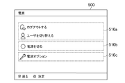
図15A及び図15Bは、本実施形態に係る表示部16に表示される電源操作画面の一例を示す図である。図15に示すように、本実施形態に係る電源操作画面500は、複数の操作画像項目510(510a、510b、510c)を含んで構成されている。操作画像項目510aは電源機能Aを選択するための項目であり、操作画像項目501aが選択操作されることにより電源機能Aが実行される。操作画像項目510aに表示される電源機能Aを示す画像は不変のものであり、例えば、“ログアウトする”、“ユーザを切り替える”などの電源機能を示す画像が常に表示されている。つまり、ユーザは、電源機能Aを実行させるためには電源操作画面を表示させればよい。操作画像項目510bは電源機能Bを選択するための項目であり、操作画像項目510bが選択操作されることにより電源機能Bが実行される。操作画像項目510bに表示される電源機能Bを示す画像は、特定の機能の使用状況に応じて切り替わるものであり、複数の表示候補の電源機能を示す画像のうち特定の機能使用状況に応じていずれか1つが表示される。本実施形態では、“スタンバイモードにする”の電源機能を示す画像、及び“電源を切る”の電源機能を示す画像が、特定の機能の使用状況に応じて切り替わって表示される。図15Aは、操作画像項目510bに“スタンバイモードにする”の電源機能を示す画像が表示された電源操作画面を示している。また、図15Bは、操作画像項目510bに“電源を切る”の電源機能を示す画像が表示された電源操作画面を示している。操作画面項目510cは電源オプションを選択するための項目である。電源オプションは、操作画像項目510a及び操作画像項目510bに表示されないその他の電源機能を示しており、操作画面項目510cが選択操作されることで、他の電源機能を選択するための電源オプション操作画面が表示される。
図16は、本実施形態に係る表示部16に表示される電源オプション操作画面の一例を示す図である。図16に示す電源オブション操作画面540は図15A及び図15Bに示す操作画像項目510cが選択操作されることで表示されるものである。ここでは、図15Aに示す操作画像項目510cが選択操作されても、図15Bに示す操作画像項目510cが選択操作されても、同じ電源オプション操作画面が表示されることとする。図16に示すように、本実施形態に係る電源オプション操作画面540は、複数の操作画像項目550(550a、550b)を含んで構成されている。操作画像項目550aは、図15A及び図15Bに示した操作画像項目510bに表示され得るすべての表示候補の電源機能Bを示す画像が表示される。この操作画像項目550aにおいて、電源操作画面500の操作画像項目510bに表示されていない他の電源機能Bの実行を選択することが可能となる。具体的には、図16に示すように、図15A及び図15Bにおいて操作画像項目510bに表示され得る表示候補の電源機能Bを示す画像である、“スタンバイモードにする”の電源機能を示す画像、及び“電源を切る”の電源機能を示す画像が操作画像項目550aに表示される。なお、図16においては、操作画像項目550aに操作画像項目510bに表示され得るすべての表示候補の電源機能Bを示す画像が表示される例を示しているが、表示候補の電源機能Bのうち操作画像項目510bに表示されていない電源機能を示す画像だけが表示されることとしてもよい。また、操作画像項目550bは、図15A及び図15Bに示した電源操作画面500には表示されない他の電源機能を示す画像が表示され、例えば“再起動する”の電源機能を示す画像が表示される。
このように、ユーザがよく使用する電源機能については電源操作画面500において選択実行できるようにし、たまにしか使用しない電源機能については電源オプション操作画面において選択実行できるようにすることで、ユーザはよく使用する電源機能を実行しやすくなる。
ここで、操作画像項目510bに表示され得る複数の表示候補の電源機能Bを示す画像が、特定の機能の使用状況に応じて切り替わる処理について具体的に説明する。本実施形態では、表示候補の電源機能Bを示す画像である、“スタンバイモードにする”の電源機能を示す画像、及び“電源を切る”の電源機能を示す画像が切り替わることとする。そして、これら2つの電源機能を示す画像の表示は、“スタンバイモード中の機能”の使用状況に応じて切り替わる。具体的には。図14に示したスタンバイモード中の機能を設定する設定画面において、複数の設定項目のうち少なくとも1つの設定項目が有効に設定されている場合に、操作画像項目510bに“スタンバイモードにする”の電源機能を示す画像が表示される。そして、図14に示したスタンバイモード中の機能を設定する設定画面において、複数の設定項目すべてが無効に設定されている場合に、操作画像項目510bに“電源を切る”の電源機能を示す画像が表示される。ここでは、スタンバイモード中の機能の設定が1つでも有効になっている場合には、ユーザがゲーム装置10の利用を終了する際に“スタンバイモードにする”の電源機能を選択することが想定され、スタンバイモード中の機能の設定がすべて無効になっている場合には、ユーザがゲーム装置10の利用を終了する際に“電源を切る”の電源機能を選択することが想定される。そこで、スタンバイモード中の機能の使用状況に応じて操作画像項目510bに表示される画像を上述のように切り替えることとしている。これにより、ユーザによる機能の使用状況に適した電源操作画面をユーザに提示することが可能となり、ユーザはよく使用する電源機能を実行しやすくなる。
ここで、本実施形態に係るゲーム装置10が実行する電源操作画面表示処理について図17のフロー図を参照して説明する。
まず、操作受付部31が電源操作画面を表示するための操作指示を受け付けると(S401)、機能使用情報取得部34が操作指示に含まれるユーザ識別子に対応する機能使用情報を機能使用状況管理テーブルTbl200から取得する(S402)。ここでは、機能使用情報取得部34は、機能使用情報として機能使用状況管理テーブルTbl200から“スタンバイモード中の機能”に関する情報を取得することとする。
そして、条件判断部33が、“スタンバイモード中の機能”に含まれる設定項目のうち少なくとも1つの設定項目が有効となっているか否かを判断する(S403)。
処理S403の判断の結果、“スタンバイモード中の機能”に含まれる設定項目のうち少なくとも1つの設定項目が有効となっていると判断された場合は(S403:Y)、表示制御部32は、図15Aに示すように電源操作画面の操作画像項目510bに“スタンバイモードにする”の電源機能を示す画像を表示する(S404)。一方で、処理S403の判断の結果、“スタンバイモード中の機能”に含まれる設定項目がすべて無効となっていると判断された場合は(S403:N)、表示制御部32は、図15Bに示すように電源機操作画面の操作画像項目510bに“電源を切る”の電源機能を示す画像を表示する。
さらに、上述したような電源操作画面を表示可能なゲーム装置10において、ユーザの電源機能の使用状況に応じて当該電源操作画面表示処理に関するメッセージ画像を表示することは特に有効となる。具体的には、スタンバイモード中の機能に含まれる設定項目を少なくとも1つ有効としているユーザが、電源オプション操作画面の操作画像項目550aから“電源を切る”の電源機能を選択して実行した場合に、“よく使用する電源オプションに簡単にアクセスできます”の表示内容のメッセージ画像を表示し、遷移先画面においてスタンバイモード中の機能に含まれる設定項目をすべて無効とすると電源操作画面に“電源を切る”の電源機能を示す画像が表示されることを知らせることとする。これにより、必要ないのにスタンバイモード中の機能の設定を有効としていたユーザや、電源操作画面表示処理について知らないユーザにも適切なタイミングで当該電源操作画面表示処理について知らせることができる。
また、スタンバイモード中の機能に含まれる設定項目を少なくとも1つ有効としているユーザが、電源オプション操作画面の操作画像項目550aから“電源を切る”の電源機能を選択して実行する頻度を考慮してメッセージ画像を表示してもよい。具体的には、電源オプション操作画面の操作画像項目550aから“電源を切る”の電源機能を選択して実行する頻度が高いユーザは、必要ないのにスタンバイモード中の機能の設定を有効としている可能性があり、電源オプション操作画面の操作画像項目550aから“電源を切る”の電源機能を選択して実行する頻度が低いユーザは、普段はスタンバイモードを実行しているが、たまに意図的に電源を切っていることが考えられる。そこで、電源オプション操作画面の操作画像項目550aから“電源を切る”の電源機能を選択して実行する頻度が高いユーザにはメッセージ画像を表示し、電源オプション操作画面の操作画像項目550aから“電源を切る”の電源機能を選択して実行する頻度が低いユーザにはメッセージ画像を表示しないこととすれば、よりユーザの機能の使用状況に応じた適切な電源機能を知らせるメッセージ画像を提示することが可能となる。
Claims (12)
- ユーザによるゲーム装置に備えられる機能の使用状況を管理する管理手段と、
前記ユーザによる所与の指示に対応付けて記憶されている前記機能に関する複数のメッセージそれぞれについて当該所与の指示に応じて表示すべきか否かを、当該ユーザの前記機能の使用状況に応じて判断する判断手段と、
前記ユーザによる所与の指示に応じて表示すべきと判断された複数の前記メッセージのうち、いずれか1つを表示するメッセージ表示制御手段と、
を含むことを特徴とするゲーム装置。 - 前記判断部が前記所与の指示に対応付けられて記憶されている前記機能を使用していないと判断した場合に、前記メッセージ表示制御手段は、前記ユーザによる前記所与の指示に応じて当該機能に関するメッセージを表示する、
ことを特徴とする請求項1に記載のゲーム装置。 - 前記メッセージ表示制御手段は、前記ユーザによる所与の指示に応じて表示すべきと判断された複数の前記メッセージのうち表示されなかったメッセージのいずれか1つを、次の前記ユーザによる所与の指示に応じて表示する、
ことを特徴とする請求項1または2に記載のゲーム装置。 - 前記判断部により前記ユーザによる所与の指示に応じて表示すべきと判断された複数の前記メッセージを格納したメッセージリストを生成するメッセージリスト生成手段と、
前記ユーザによる指示にしたがって前記メッセージリストを示すメッセージリスト画像を表示するメッセージリスト表示手段と、をさらに含む、
ことを特徴とする請求項1から3のいずれか一項に記載のゲーム装置。 - 前記メッセージリスト生成手段は、前記判断手段が前記ユーザによる所与の指示に応じて表示すべきと判断した順に前記メッセージを格納する、
ことを特徴とする請求項4に記載のゲーム装置。 - 前記表示されたメッセージが前記ユーザにより選択指示されることで、当該メッセージが示す機能に関する情報が示される遷移画面を表示する遷移画面表示制御手段、をさらに含む、
ことを特徴とする請求項1から5のいずれか一項に記載のゲーム装置。 - 前記管理手段は、前記ゲーム装置を使用する複数のユーザそれぞれについて前記ゲーム装置に備えられる機能の使用状況を管理し、
前記判断手段は、前記ユーザによる所与の指示に対応付けて記憶されている前記機能に関するメッセージを当該所与の指示に応じて表示するか否かを、当該ユーザに対応する前記機能の使用状況に応じて判断する、
ことを特徴とする請求項1から6のいずれか一項に記載のゲーム装置。 - 電源をスタンバイ状態または切状態にするための操作画像を含む電源操作画面を表示する電源操作画面表示手段と、
前記電源がスタンバイ状態において使用可能な機能の設定状況を示す情報を取得する取得手段と、
を含み、
前記スタンバイ状態において使用可能な機能の設定状況に応じて、前記電源操作画面表示手段は、前記電源をスタンバイ状態にする前記操作画像、または、前記電源を切状態にする前記操作画像、を前記電源操作画面に含める、
ことを特徴とするゲーム装置。 - 電源をスタンバイ状態または切状態にするための操作画像を含む電源操作画面を表示する電源操作画面表示手段、
前記電源がスタンバイ状態において使用可能な機能の設定状況を示す情報を取得する取得手段、
を含み、
前記スタンバイ状態において使用可能な機能の設定状況に応じて、前記電源操作画面表示手段は、前記電源をスタンバイ状態にする前記操作画像、または、前記電源を切状態にする前記操作画像、を前記電源操作画面に含める、
ことを特徴とするゲーム装置の制御方法。 - 電源をスタンバイ状態または切状態にするための操作画像を含む電源操作画面を表示する電源操作画面表示手段、
前記電源がスタンバイ状態において使用可能な機能の設定状況を示す情報を取得する取得手段、
としてゲーム装置を機能させるためのプログラムであって、
前記スタンバイ状態において使用可能な機能の設定状況に応じて、前記電源操作画面表示手段は、前記電源をスタンバイ状態にする前記操作画像、または、前記電源を切状態にする前記操作画像、を前記電源操作画面に含める、
ことを特徴とするプログラム。 - ユーザによるゲーム装置に備えられる機能の使用状況を管理する管理手段と、
前記ユーザによる所与の指示に対応付けて記憶されている前記機能に関する複数のメッセージそれぞれについて当該所与の指示に応じて表示すべきか否かを、当該ユーザの前記機能の使用状況に応じて判断する判断手段と、
前記ユーザによる所与の指示に応じて表示すべきと判断された複数の前記メッセージのうち、いずれか1つを表示するメッセージ表示制御手段と、
を含むことを特徴とするゲーム装置の制御方法。 - ユーザによるゲーム装置に備えられる機能の使用状況を管理する管理手段、
前記ユーザによる所与の指示に対応付けて記憶されている前記機能に関する複数のメッセージそれぞれについて当該所与の指示に応じて表示すべきか否かを、当該ユーザの前記機能の使用状況に応じて判断する判断手段、
前記ユーザによる所与の指示に応じて表示すべきと判断された複数の前記メッセージのうち、いずれか1つを表示するメッセージ表示制御手段、
としてゲーム装置を機能させるためのプログラム。
Priority Applications (2)
| Application Number | Priority Date | Filing Date | Title |
|---|---|---|---|
| US15/552,908 US10300396B2 (en) | 2015-02-27 | 2016-02-19 | Game apparatus, controlling method for game apparatus, and program |
| JP2017502335A JP6449980B2 (ja) | 2015-02-27 | 2016-02-19 | ゲーム装置、ゲーム装置の制御方法、及びプログラム |
Applications Claiming Priority (2)
| Application Number | Priority Date | Filing Date | Title |
|---|---|---|---|
| JP2015-039490 | 2015-02-27 | ||
| JP2015039490 | 2015-02-27 |
Publications (1)
| Publication Number | Publication Date |
|---|---|
| WO2016136639A1 true WO2016136639A1 (ja) | 2016-09-01 |
Family
ID=56788737
Family Applications (1)
| Application Number | Title | Priority Date | Filing Date |
|---|---|---|---|
| PCT/JP2016/054945 Ceased WO2016136639A1 (ja) | 2015-02-27 | 2016-02-19 | ゲーム装置、ゲーム装置の制御方法、及びプログラム |
Country Status (3)
| Country | Link |
|---|---|
| US (1) | US10300396B2 (ja) |
| JP (2) | JP6449980B2 (ja) |
| WO (1) | WO2016136639A1 (ja) |
Families Citing this family (2)
| Publication number | Priority date | Publication date | Assignee | Title |
|---|---|---|---|---|
| JP2018005091A (ja) * | 2016-07-06 | 2018-01-11 | 富士通株式会社 | 表示制御プログラム、表示制御方法および表示制御装置 |
| WO2024195619A1 (ja) | 2023-03-20 | 2024-09-26 | ソニーグループ株式会社 | 携帯端末装置、提案表示方法及びプログラム |
Citations (3)
| Publication number | Priority date | Publication date | Assignee | Title |
|---|---|---|---|---|
| JP2008009573A (ja) * | 2006-06-28 | 2008-01-17 | Hitachi Software Eng Co Ltd | 提案型操作支援システム及びプログラム |
| JP2010108032A (ja) * | 2008-10-28 | 2010-05-13 | Kyocera Mita Corp | 電子機器 |
| JP2014164599A (ja) * | 2013-02-26 | 2014-09-08 | Nec Saitama Ltd | 情報機器、その制御方法及びプログラム |
Family Cites Families (4)
| Publication number | Priority date | Publication date | Assignee | Title |
|---|---|---|---|---|
| JPH05250120A (ja) * | 1992-03-04 | 1993-09-28 | Nec Corp | メッセージ表示制御システム |
| JPH11143616A (ja) * | 1997-11-10 | 1999-05-28 | Sega Enterp Ltd | 文字通信装置 |
| CN102473144B (zh) * | 2010-06-03 | 2015-02-11 | 索尼计算机娱乐公司 | 信息处理装置 |
| WO2012101863A1 (ja) * | 2011-01-24 | 2012-08-02 | 株式会社ソニー・コンピュータエンタテインメント | 情報処理装置 |
-
2016
- 2016-02-19 WO PCT/JP2016/054945 patent/WO2016136639A1/ja not_active Ceased
- 2016-02-19 US US15/552,908 patent/US10300396B2/en active Active
- 2016-02-19 JP JP2017502335A patent/JP6449980B2/ja active Active
-
2018
- 2018-12-06 JP JP2018228909A patent/JP6715914B2/ja active Active
Patent Citations (3)
| Publication number | Priority date | Publication date | Assignee | Title |
|---|---|---|---|---|
| JP2008009573A (ja) * | 2006-06-28 | 2008-01-17 | Hitachi Software Eng Co Ltd | 提案型操作支援システム及びプログラム |
| JP2010108032A (ja) * | 2008-10-28 | 2010-05-13 | Kyocera Mita Corp | 電子機器 |
| JP2014164599A (ja) * | 2013-02-26 | 2014-09-08 | Nec Saitama Ltd | 情報機器、その制御方法及びプログラム |
Non-Patent Citations (2)
| Title |
|---|
| "PS4 Hatsubai Countdown Event Kaisaichu no New York de ''inFAMOUS:Second Son", O ASONDEKITA! SCE YOSHIDA SAN ENO INTERVIEW MO KEISAI, 15 November 2013 (2013-11-15), Retrieved from the Internet <URL:http://dengekionline.com/elem/000/000/752/752931> [retrieved on 20160426] * |
| "When You Don't Want Your Laptop to Go to Sleep", PCWORLD, 28 July 2011 (2011-07-28), Retrieved from the Internet <URL:http://www.pcworld.com/article/231154/laptop_sleep.html> [retrieved on 20160426] * |
Also Published As
| Publication number | Publication date |
|---|---|
| JPWO2016136639A1 (ja) | 2017-08-31 |
| US20180028921A1 (en) | 2018-02-01 |
| JP6449980B2 (ja) | 2019-01-09 |
| JP2019063554A (ja) | 2019-04-25 |
| JP6715914B2 (ja) | 2020-07-01 |
| US10300396B2 (en) | 2019-05-28 |
Similar Documents
| Publication | Publication Date | Title |
|---|---|---|
| JP4886063B2 (ja) | 状態報知装置、状態報知方法及びプログラム | |
| JP2023179578A5 (ja) | ||
| US10459605B2 (en) | Information processing system, non-transitory storage medium encoded with computer readable information processing program, information processing method, and information processing terminal | |
| JP5501546B2 (ja) | ゲームシステム、ゲーム装置およびゲームプログラム | |
| JP2016158830A (ja) | ゲームシステム、コントローラ、ゲーム装置、ゲーム装置の制御方法、及びプログラム | |
| US11074059B2 (en) | Non-transitory computer-readable recording medium storing instructions controlling operation of mobile terminal | |
| JP5585721B2 (ja) | 情報装置、画面切替え方法、及び画面切替えプログラム | |
| JP4478001B2 (ja) | 画像表示装置、画像表示方法及びプログラム | |
| JP6715914B2 (ja) | ゲーム装置、ゲーム装置の制御方法、及びプログラム | |
| JP2013025426A (ja) | 画像出力装置及びそのプログラム | |
| JP2016134758A (ja) | 制御装置、制御装置の制御プログラム、制御装置の制御方法、制御システム、端末装置、および被制御装置 | |
| JP6240627B2 (ja) | 情報処理装置および画面生成方法 | |
| JP7402450B2 (ja) | ロボット制御装置、ロボット制御方法及びロボット制御システム | |
| JP2013197696A (ja) | 携帯端末、情報表示システムおよび情報表示方法 | |
| JP6603772B2 (ja) | 情報処理システム、情報処理プログラム、情報処理方法、情報処理端末 | |
| JP2018110709A (ja) | 振動制御システム、振動制御装置、振動制御プログラムおよび振動制御方法 | |
| JP6376120B2 (ja) | 端末プログラム及び端末装置 | |
| JP2010097425A (ja) | 表示制御装置、処理実行装置及びプログラム | |
| JP2016162069A (ja) | 情報処理装置および画面生成方法 | |
| JP2024075930A (ja) | 画像処理装置 | |
| WO2007129498A1 (ja) | 情報処理システム及びコンピュータの制御方法 | |
| JP6128838B2 (ja) | 情報処理装置、その制御方法、プログラム | |
| JP2022094120A (ja) | 操作装置、操作方法及びプログラム | |
| JP2005310032A (ja) | 処理結果出力装置及び処理結果出力装置プログラム | |
| JPH09276549A (ja) | Tvゲームシステム |
Legal Events
| Date | Code | Title | Description |
|---|---|---|---|
| 121 | Ep: the epo has been informed by wipo that ep was designated in this application |
Ref document number: 16755385 Country of ref document: EP Kind code of ref document: A1 |
|
| ENP | Entry into the national phase |
Ref document number: 2017502335 Country of ref document: JP Kind code of ref document: A |
|
| NENP | Non-entry into the national phase |
Ref country code: DE |
|
| 122 | Ep: pct application non-entry in european phase |
Ref document number: 16755385 Country of ref document: EP Kind code of ref document: A1 |