WO2016136602A1 - メッシュフィルタ - Google Patents
メッシュフィルタ Download PDFInfo
- Publication number
- WO2016136602A1 WO2016136602A1 PCT/JP2016/054798 JP2016054798W WO2016136602A1 WO 2016136602 A1 WO2016136602 A1 WO 2016136602A1 JP 2016054798 W JP2016054798 W JP 2016054798W WO 2016136602 A1 WO2016136602 A1 WO 2016136602A1
- Authority
- WO
- WIPO (PCT)
- Prior art keywords
- filter
- fluid
- mesh filter
- bars
- vertical
- Prior art date
- Legal status (The legal status is an assumption and is not a legal conclusion. Google has not performed a legal analysis and makes no representation as to the accuracy of the status listed.)
- Ceased
Links
Images


Classifications
-
- B—PERFORMING OPERATIONS; TRANSPORTING
- B01—PHYSICAL OR CHEMICAL PROCESSES OR APPARATUS IN GENERAL
- B01D—SEPARATION
- B01D29/00—Filters with filtering elements stationary during filtration, e.g. pressure or suction filters, not covered by groups B01D24/00 - B01D27/00; Filtering elements therefor
- B01D29/01—Filters with filtering elements stationary during filtration, e.g. pressure or suction filters, not covered by groups B01D24/00 - B01D27/00; Filtering elements therefor with flat filtering elements
-
- F—MECHANICAL ENGINEERING; LIGHTING; HEATING; WEAPONS; BLASTING
- F16—ENGINEERING ELEMENTS AND UNITS; GENERAL MEASURES FOR PRODUCING AND MAINTAINING EFFECTIVE FUNCTIONING OF MACHINES OR INSTALLATIONS; THERMAL INSULATION IN GENERAL
- F16L—PIPES; JOINTS OR FITTINGS FOR PIPES; SUPPORTS FOR PIPES, CABLES OR PROTECTIVE TUBING; MEANS FOR THERMAL INSULATION IN GENERAL
- F16L55/00—Devices or appurtenances for use in, or in connection with, pipes or pipe systems
- F16L55/24—Preventing accumulation of dirt or other matter in pipes, e.g. by traps, by strainers
Definitions
- the present invention relates to a mesh filter used for filtering out foreign substances in a fluid, and more particularly to a mesh filter having a self-cleaning function.
- a mesh filter is disposed in the middle of an oil pipe such as a fuel supply pipe or a lubrication device connected to a fuel injection device of an automobile, and foreign matters in a fluid such as fuel and oil are filtered by the mesh filter. ing.
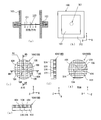
- FIG. 6 is a diagram showing such a conventional mesh filter 100.
- 6A is a cross-sectional view showing a simplified state of use of the mesh filter 100
- FIG. 6B is a plan view of the mesh filter 100
- FIG. 6C is FIG. 6B.
- FIG. 6D is a cross-sectional view taken along line A5-A5 in FIG. 6C
- FIG. 6E is an A6 view in FIG. 6C.
- FIG. 6 is a cross-sectional view taken along line -A6, and FIG.
- the mesh filter 100 shown in FIG. 6 includes a filter part 101 that filters out foreign substances in the fluid, and a frame body 102 that is integrally formed on the outer periphery of the filter part 101.
- the mesh filter 100 is formed by injecting molten resin into a cavity of a mold, and a frame body 102 is fixed to a pipe 103 or the like, and the filter unit 101 is arranged so as to be orthogonal to the fluid flow.
- the mesh filter 100 has a plurality of vertical bars 104 on the front surface side and a plurality of vertical bars 104 on the back surface side so that the molten resin can be smoothly filled into the cavity during injection molding.
- a horizontal crosspiece 105 see Patent Document 1.
- the filter unit 101 of the mesh filter 100 is formed in parallel with the XY plane, the vertical beam 104 extends along the Y axis, and the horizontal beam 105 extends along the X axis so as to be orthogonal to the vertical beam 104.
- the plurality of vertical bars 104 are arranged in parallel with the Y axis and at equal intervals, and the plurality of horizontal bars 105 are arranged in parallel with the X axis at equal intervals, and are adjacent to the adjacent vertical bars 104, 104.
- An opening 106 that allows passage of fluid is formed between 105 and 105.
- an object of the present invention is to provide a mesh filter in which clogging of the filter portion is unlikely to occur.
- the present invention relates to a mesh filter 1 including a filter unit 6 that filters out foreign matter 15 in a fluid and a frame body unit 10 that supports the filter unit 6.
- the filter portion 6 has a front surface side portion 6a and a back surface side portion 6b, and is disposed so as to obliquely block the flow of the fluid.
- the front surface side portion 6a of the filter portion 6 is disposed upstream of the fluid flow with respect to the back surface side portion 6b of the filter portion 6 and extends along the fluid flow direction. It comprises a plurality of vertical rails 12 extending across the flow.
- the back surface side portion 6 b of the filter unit 6 is arranged on the downstream side of the fluid flow with respect to the front surface side portion 6 a of the filter unit 6, and a plurality of horizontal beams 13 intersecting the vertical beam 12.
- a portion of the horizontal beam 13 that intersects with the vertical beam 12 is formed integrally with the vertical beam 12.
- a portion of the filter unit 6 where the vertical beam 12 and the horizontal beam 13 do not intersect with each other is an opening 14 that allows the fluid to pass therethrough.
- the foreign matter filtered off by the filter unit is pushed along the vertical rail of the filter unit by the flow of the fluid, so that the opening of the filter unit is cleaned by the flow of the fluid, No clogging for a long time.
- FIG. 1 (a) is the external appearance perspective view which looked at the mesh filter from diagonally right upper
- FIG.1 (b) is the front view (figure which shows a bottom face) of a mesh filter )
- FIG. 1C is a side view of the mesh filter
- FIG. 1D is a sectional view of the mesh filter cut along the line A1-A1 of FIG. 1C
- FIG. 1C shows the mesh filter of FIG. 1C as viewed from the direction of arrow C1 (plan view)
- FIG. 1F shows the mesh filter of FIG. 1C as viewed from the direction of arrow C2 (back view).
- FIG. 1G is a side view showing the mesh filter of FIG.
- FIG. 2A is a diagram illustrating an attachment state of the mesh filter, in which FIG. 2A is an attachment state diagram of the mesh filter as viewed from the upstream side to the downstream side of the fluid piping, and FIG. 2B is FIG.
- FIG. 6 is a cross-sectional view showing a mesh filter attached state cut along the line A2-A2. It is a figure which shows the detail of a filter part, FIG.3 (a) is a figure which expands and shows B1 part (a part of back surface side part) of the filter part of FIG.1 (g), FIG.3 (b) is FIG.
- FIG. 3A is a cross-sectional view taken along line A3-A3 in FIG. 3A, FIG.
- FIG. 3C is a cross-sectional view taken along line A4-A4 in FIG. 3A, and FIG. It is a figure which expands and shows a part of surface side part of a filter part. It is a figure for demonstrating the self-cleaning function of the mesh filter which concerns on embodiment of this invention.
- FIG. 5A is an external perspective view of a mesh filter according to Modification 1
- FIG. 5B is an external perspective view of a mesh filter according to Modification 2
- 6A and 6B are diagrams showing a conventional mesh filter, in which FIG. 6A is a simplified cross-sectional view showing the state of use of the mesh filter, FIG. 6B is a plan view of the mesh filter, and FIG. FIG.
- FIG. 6 (d) is a sectional view taken along line A5-A5 in FIG. 6 (c), and FIG. 6 (e) is A6-A6 in FIG. 6 (c). Sectional drawing cut
- FIG. 1 is a diagram showing a mesh filter 1 according to an embodiment of the present invention.
- 1A is an external perspective view of the mesh filter 1 as viewed obliquely from the upper right
- FIG. 1B is a front view of the mesh filter 1 (showing the bottom surface).
- FIG. 1 is a side view of the mesh filter 1
- FIG. 1D is a sectional view of the mesh filter 1 cut along the line A1-A1 of FIG. 1C
- FIG. 2C is a diagram (plan view) showing the mesh filter 1 of FIG. 1C viewed from the direction of the arrow C1
- FIG. 1F is a diagram showing the mesh filter 1 of FIG. 1 (g) is a side view showing the mesh filter 1 of FIG. 1 (b) as viewed from the direction of arrow C3.
- the mesh filter 1 is a polyhedron having a substantially triangular prism shape with a hollow interior 2, and fluid is introduced into the interior 2 by a fluid inlet 4 formed on one side surface 3a of the three side surfaces 3a to 3c.
- a flange-like portion 5 is integrally formed around the fluid inlet 4.
- the other two side surfaces 3b and 3c other than the one side surface 3a where the fluid introduction port 4 is formed among the three side surfaces 3a to 3c are provided with a filter unit 6 for filtering out foreign matters in the fluid, And a frame portion 7 integrally formed around the filter portion 6.
- the pair of triangular bottom surfaces 8 a and 8 b are formed of a triangular plate-like member on which the filter portion 6 is not formed, and together with the frame portion 7 integrally formed around the filter portion 6, A frame body portion 10 that supports the filter portion 6 is configured.
- the mesh filter 1 as a whole is integrally formed of resin (POM (polyacetal), 66 nylon, etc.).
- the filter unit 6 is a quadrangular region provided on the side surfaces 3b and 3c.
- the frame portion 7 is formed along the outer edge (four sides) of the rectangular filter portion 6.
- the fluid inlet 4 is formed in almost the whole area of the one side surface 3a, and has a rectangular shape similar to the shape of the one side surface 3a.
- FIG. 2 is a diagram showing the attachment state of the mesh filter 1.
- 2A is an attached state diagram of the mesh filter 1 as seen from the upstream side to the downstream side of the fluid piping 11.
- FIG. 2B is a cross-sectional view showing an attached state of the mesh filter 1 cut along the line A2-A2 of FIG.
- the fluid introduction port 4 opens toward the upstream side of the pipe 11, and the flange-like portion 5 connects the connection flange portion 11c of the upstream side pipe 11a and the downstream side pipe 11b.
- a portion (triangular prism-shaped portion) other than the flange-shaped portion 5 is accommodated in the pipe 11 while being fixed to the flange portion 11 c.
- the fluid inlet 4 of the mesh filter 1 has a quadrangular shape, and the fluid flow flowing down the upstream side pipe 11 a is introduced into the inside 2 of the mesh filter 1.
- the fluid that has flowed into the interior 2 of the mesh filter 1 is filtered to remove foreign matters when passing through the pair of filter portions 6 and 6, and then flows toward the downstream pipe 11b.
- the mesh filter 1 attached to the pipe 11 is positioned so that the filter parts 6 and 6 obliquely block the flow of fluid in the pipe 11.
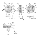
- FIG. 3 is a diagram showing details of the filter unit 6.
- 3 (a) is an enlarged view of the B1 portion (a part of the back side portion) of the filter portion 6 of FIG. 1 (g), and
- FIG. 3 (b) is an A3 view of FIG. 3 (a).
- FIG. 3C is a cross-sectional view taken along line A3
- FIG. 3C is a cross-sectional view taken along line A4-A4 in FIG. 3A
- FIG. FIG. 6 is an enlarged view showing a part of the surface side portion of the portion 6.
- the filter unit 6 includes a surface side portion 6a that is a portion disposed on the upstream side of the fluid flow, and a back surface side portion 6b that is a portion disposed on the downstream side of the fluid flow with respect to the surface side portion 6a. It is divided in two.
- the surface side portion 6a of the filter unit 6 is composed of a plurality of vertical bars 12 extending along the direction of fluid flow.
- the plurality of vertical bars 12 are arranged in parallel to the Y axis and at equal intervals.
- the back surface side portion 6 b of the filter unit 6 is composed of a plurality of horizontal bars 13 orthogonal to the vertical bars 12 of the front surface side part 6 a of the filter unit 6.
- the plurality of horizontal rails 13 are arranged in parallel to the X axis at equal intervals, and a portion intersecting with the vertical rail 12 is formed integrally with the vertical rail 12.
- the portions where the plurality of vertical bars 12 and the plurality of horizontal bars 13 do not intersect with each other are openings 14 that allow fluid to pass therethrough.
- the opening 14 is a rectangular space formed between a pair of adjacent vertical bars 12, 12 and a pair of adjacent horizontal bars 13, 13 that are perpendicular to the vertical bars 12, 12.
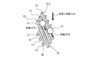
- FIG. 4 is a diagram for explaining the self-cleaning function of the mesh filter 1 according to the present embodiment.
- the filter portion 6 of the mesh filter 1 passes through the opening portion 14 because the vertical rail 12 extends along the fluid flow direction and obliquely crosses the fluid flow.
- the foreign matter 15 filtered out without being moved is pushed by the fluid and moves along the vertical rail 12.
- the filter unit 6 is cleaned by the flow of the fluid, and the opening 14 is less likely to be clogged by the foreign matter 15 filtered out.
- the width L1 of the horizontal beam 13 is formed to 0.1 mm
- the width L2 of the vertical beam 12 is formed to 0.1 mm
- the length L3 of one side of the opening 14 is 0. .1 mm (see FIG. 3).
- the dimensions of L1 to L3 are examples for assisting understanding of the mesh filter 1 according to the present embodiment, and are not limited to these numerical values, and are appropriately changed according to use conditions and the like.
- the foreign matter 15 filtered out by the filter unit 6 is pushed away along the vertical rail 12 of the filter unit 6 by the flow of the fluid. 14 is cleaned by the flow of fluid and does not clog for a long time.
- the mesh filter 1 As shown in FIG. 2, the mesh filter 1 according to the present embodiment has a triangular corner portion formed by abutting the tips of a pair of side surfaces 3b and 3c having the filter portion 6, and this triangular corner portion. Is a foreign substance reservoir 16 for collecting foreign substances pushed away along the vertical beam 12.
- the foreign substance reservoir 16 is located at the end in the longitudinal direction of the vertical rail 12 and at the downstream end in the fluid flow direction inside the mesh filter 1. Since the mesh filter 1 having such a configuration can store the filtered foreign matter 15 in the foreign matter reservoir 16, the frequency of cleaning operations such as cleaning can be reduced.
- the foreign matter reservoir 16 is connected to an external foreign matter removing device 17 via a drain tube 18 or the like, and the foreign matter 15 accumulated in the foreign matter reservoir 16 is periodically removed by the foreign matter removing device 17. It may be discharged to the outside.
- the mesh filter 1 configured in this way can further reduce the frequency of cleaning operations such as cleaning.
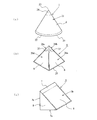
- FIG. 5A is an external perspective view showing Modification 1 of the mesh filter.
- the mesh filter 1 according to the first modification has a conical shape with a hollow inside, a fluid introduction port is formed on the bottom surface 20, and the filter portion 6 is formed on the conical surface 21.
- the conical surface 21 is formed by integrally forming an annular frame portion 22 along the bottom surface 20, a conical frame portion 24 on the top portion 23 side, and a filter portion 6 supported by these frame portions 22, 24. Yes.
- the mesh filter 1 having such a shape obtains the same effect as the mesh filter 1 of the above-described embodiment by arranging the filter portion 6 formed on the conical surface 21 so as to obliquely block the flow of fluid. Can do.
- the conical mesh filter 1 may be a frustoconical mesh filter having a shape in which the top 23 side is partially cut away.
- FIG. 5B is an external perspective view showing a second modification of the mesh filter 1.
- the mesh filter 1 according to Modification 2 has a hollow quadrangular pyramid shape, a fluid introduction port is formed on the bottom surface 25, and the filter unit 6 is formed on all of the four side surfaces 26a to 26d.
- the side surfaces 26 a to 26 d have an isosceles triangle shape, and are formed so as to surround the isosceles trapezoidal filter portion 6 with the frame portion 27.
- the mesh filter 1 having such a shape obtains the same effect as the mesh filter 1 of the above embodiment by arranging the filter portion 6 formed on the side surfaces 26a to 26d so as to obliquely block the flow of fluid. be able to.
- the mesh filter 1 exemplifies a mode in which the filter unit 6 is formed on all of the four side surfaces 26a to 26d.
- the present invention is not limited to this, and is not limited to this.
- the filter unit 6 may be formed on the side surface, the two side surfaces, or the three side surfaces.
- FIG. 5C is an external perspective view showing a third modification of the mesh filter 1.
- the mesh filter 1 according to the third modification is a triangular prism-shaped polyhedron having a hollow inside, the bottom surface 8 has a right triangle, and one side surface 3a (two orthogonal side surfaces 3a, 3a, 3a, 3c)
- a fluid introduction port is formed on one side surface 3a) of 3c
- a filter portion 6 is formed on one side surface 3b that obliquely connects two side surfaces 3a and 3c orthogonal to each other.
- One side surface 3b that obliquely connects the two orthogonal side surfaces 3a and 3c has a rectangular shape, and is formed so as to surround the rectangular filter portion 6 with the frame portion 7.
- the mesh filter 1 having such a shape obtains the same effect as that of the mesh filter 1 of the above embodiment by arranging the filter portion 6 formed on the one side surface 3b so as to obliquely block the flow of fluid. Can do.
- the cylindrical mesh filter 1 according to the present embodiment exemplifies a case where the shape of the opening 14 is square, but is not limited thereto, and the shape of the opening 14 may be rectangular. Further, the mesh filter 1 according to the present invention is not limited to the polyhedrons exemplified in the above-described embodiment, modification 2 and modification 3, and may be a pentahedron or hexagonal pyramid.
- SYMBOLS 1 Mesh filter, 6 ... Filter part, 6a ... Front side part, 6b ... Back side part, 10 ... Frame body part, 12 ... Vertical beam, 13 ... Horizontal beam, 14 ... Opening part , 15 ... Foreign matter
Landscapes
- Engineering & Computer Science (AREA)
- General Engineering & Computer Science (AREA)
- Mechanical Engineering (AREA)
- Chemical & Material Sciences (AREA)
- Chemical Kinetics & Catalysis (AREA)
- Lubrication Details And Ventilation Of Internal Combustion Engines (AREA)
- Filtration Of Liquid (AREA)
- Filtering Materials (AREA)
Abstract
【課題】フィルタ部の目詰まりが生じにくいメッシュフィルタを提供する。 【解決手段】メッシュフィルタ1は、流体中の異物15を濾し取るフィルタ部6と、フィルタ部6を支持する枠体部と、を備えている。フィルタ部6は、表面側部分6aと裏面側部分6bとを有し、流体の流れを斜めに遮るように配置される。フィルタ部6の表面側部分6aは、フィルタ部6の裏面側部分6bよりも流体の流れの上流側に配置され、流体の流れの方向に沿って延びる複数の縦桟12で構成されている。フィルタ部6の裏面側部分6bは、フィルタ部6の表面側部分6aよりも流体の流れの下流側に配置され、縦桟12と交差する複数の横桟13で構成され、横桟13の縦桟12と交差する部分が縦桟12と一体に形成されている。そして、フィルタ部6の縦桟12と横桟13の交差しない部分は、流体の通過を可能にする開口部14になっている。
Description
この発明は、流体中の異物を濾し取るために使用するメッシュフィルタに関し、特に、セルフクリーニング機能を備えたメッシュフィルタに関するものである。
例えば、自動車の燃料噴射装置に接続される燃料供給管や潤滑装置等のオイル配管の途中にはメッシュフィルタが配置され、このメッシュフィルタで燃料やオイル等の流体中の異物を濾し取るようになっている。
図6は、このような従来のメッシュフィルタ100を示す図である。なお、図6(a)はメッシュフィルタ100の使用状態を簡単化して示す断面図であり、図6(b)はメッシュフィルタ100の平面図であり、図6(c)は図6(b)のB2部の拡大図であり、図6(d)は図6(c)のA5-A5線に沿って切断して示す断面図であり、図6(e)は図6(c)のA6-A6線に沿って切断して示す断面図であり、図6(f)はメッシュフィルタ100の裏面図である。
この図6に示すメッシュフィルタ100は、流体中の異物を濾し取るフィルタ部101と、このフィルタ部101の外周に一体に形成された枠体102と、を備えている。このメッシュフィルタ100は、金型のキャビティ内に溶融樹脂を射出することにより形作られ、枠体102が配管103等に固定され、フィルタ部101が流体の流れに直交するように配置されて使用される。そして、このメッシュフィルタ100は、射出成形時におけるキャビティ内への溶融樹脂の充填を円滑に行えるようにするため、フィルタ部101が表面側に位置する複数の縦桟104と裏面側に位置する複数の横桟105とで構成されている(特許文献1参照)。
メッシュフィルタ100のフィルタ部101は、X-Y平面と平行に形成され、縦桟104がY軸に沿って延び、横桟105が縦桟104と直交するようにX軸に沿って延びており、複数の縦桟104がY軸と平行で且つ等間隔で配置され、複数の横桟105がX軸と平行で且つ等間隔に配置され、隣り合う縦桟104,104間と隣り合う横桟105,105間に流体の通過を許す開口部106が形成されている。
しかしながら、図6に示す従来のメッシュフィルタ100は、フィルタ部101の縦桟104が流体の流れの上流側に配置される場合、隣り合う縦桟104,104間に異物が詰まり、フィルタ部101の横桟105が流体の流れの上流側に配置される場合、隣り合う横桟105,105間に異物が詰まる。そして、図6に示す従来のメッシュフィルタ100は、フィルタ部101に目詰まりが生じると、配管103等から取り外され、フィルタ部101の目詰まりを解消するためにフィルタ部101が洗浄等されるようになっている。したがって、目詰まりしたメッシュフィルタ100を新たなメッシュフィルタ100に交換する間、流体の流れを停止させなければならなかった。そのため、メッシュフィルタ100を使用する自動車業界等からフィルタ部101の目詰まりが生じにくいメッシュフィルタ100の提供が求められていた。
そこで、本発明は、フィルタ部の目詰まりが生じにくいメッシュフィルタの提供を目的とする。
本発明は、流体中の異物15を濾し取るフィルタ部6と、前記フィルタ部6を支持する枠体部10と、を備えたメッシュフィルタ1に関するものである。本発明において、前記フィルタ部6は、表面側部分6aと裏面側部分6bとを有し、前記流体の流れを斜めに遮るように配置される。また、前記フィルタ部6の前記表面側部分6aは、前記フィルタ部6の前記裏面側部分6bよりも前記流体の流れの上流側に配置され、前記流体の流動方向に沿うように延び且つ前記流体の流れを横切るように延びる複数の縦桟12で構成されている。また、前記フィルタ部6の前記裏面側部分6bは、前記フィルタ部6の前記表面側部分6aよりも前記流体の流れの下流側に配置され、前記縦桟12と交差する複数の横桟13で構成され、前記横桟13の前記縦桟12と交差する部分が前記縦桟12と一体に形成されている。そして、前記フィルタ部6の前記縦桟12と前記横桟13の交差しない部分は、前記流体の通過を可能にする開口部14になっている。
本発明に係るメッシュフィルタは、フィルタ部で濾し取られた異物が流体の流れによってフィルタ部の縦桟に沿って押し流されるため、フィルタ部の開口部が流体の流れによってクリーニングされた状態になり、長期間目詰まりを生じない。
以下、本発明の実施形態を図面に基づき詳述する。
図1は、本発明の実施形態に係るメッシュフィルタ1を示す図である。なお、図1(a)はメッシュフィルタ1を右斜め上から見た外観斜視図であり、図1(b)はメッシュフィルタ1の正面図(底面を示す図)であり、図1(c)はメッシュフィルタ1の側面図であり、図1(d)は図1(c)のA1-A1線に沿って切断して示すメッシュフィルタ1の断面図であり、図1(e)は図1(c)のメッシュフィルタ1を矢印C1の方向から見て示す図(平面図)であり、図1(f)は図 1(c)のメッシュフィルタ1を矢印C2の方向から見て示す図(裏面図)であり、図1(g)は図1(b)のメッシュフィルタ1を矢印C3の方向から見て示す側面図である。
図1に示すように、メッシュフィルタ1は、内部2が空洞の略三角柱状の多面体であり、三側面3a~3cのうちの一側面3aに形成された流体導入口4によって内部2に流体を導き入れるようになっており、この流体導入口4の周囲にフランジ状部分5が一体に形成されている。そして、このメッシュフィルタ1において、三側面3a~3cのうちの流体導入口4が形成された一側面3aを除く他の二側面3b,3cは、流体中の異物を濾し取るフィルタ部6と、このフィルタ部6の周囲に一体に形成された額縁部7と、を備えている。また、このメッシュフィルタ1において、三角形状の一対の底面8a,8bは、フィルタ部6が形成されていない三角板状部材で形作られ、フィルタ部6の周囲に一体に形成された額縁部7と共に、フィルタ部6を支持する枠体部10を構成している。このようなメッシュフィルタ1は、全体が樹脂(POM(ポリアセタール)、66ナイロン等)によって一体に形成されている。なお、本実施形態において、フィルタ部6は、側面3b,3cに設けられた四角形状の領域である。また、額縁部7は、矩形形状のフィルタ部6の外縁(四辺)に沿って形成されている。また、流体導入口4は、一側面3aのほぼ全域に形成されており、一側面3aの形状と同様の四角形状になっている。
図2は、メッシュフィルタ1の取付状態を示す図である。なお、図2(a)は、流体の配管11の上流側から下流側に向かって見て示すメッシュフィルタ1の取付状態図である。また、図2(b)は、図2(a)のA2-A2線に沿って切断して示すメッシュフィルタ1の取付状態を示す断面図である。
この図2に示すように、メッシュフィルタ1は、流体導入口4が配管11の上流側に向けて開口し、フランジ状部分5が上流側配管11aの接続フランジ部11cと下流側配管11bの接続フランジ部11cとの間に固定され、フランジ状部分5以外の部分(三角柱状の部分)が配管11内に収容される。このメッシュフィルタ1の流体導入口4は、四角形状になっており、上流側配管11aを流下する流体の流れをメッシュフィルタ1の内部2に導き入れるようになっている。そして、メッシュフィルタ1の内部2に流入した流体は、一対のフィルタ部6,6を通過する際に異物が濾し取られ、その後に下流側配管11b側へ流動する。このように配管11に取り付けられたメッシュフィルタ1は、フィルタ部6,6が配管11内の流体の流れを斜めに遮るように位置している。
図3は、フィルタ部6の詳細を示す図である。なお、図3(a)は図1(g)のフィルタ部6のB1部(裏面側部分の一部)を拡大して示す図であり、図3(b)は図3(a)のA3-A3線に沿って切断して示す断面図であり、図3(c)は図3(a)のA4-A4線に沿って切断して示す断面図であり、図3(d)はフィルタ部6の表面側部分の一部を拡大して示す図である。
フィルタ部6は、流体の流れの上流側に配置される部分である表面側部分6aと、この表面側部分6aよりも流体の流れの下流側に配置される部分である裏面側部分6bとに二分されている。フィルタ部6の表面側部分6aは、流体の流れの方向に沿って延びる複数の縦桟12で構成されている。そして、この複数の縦桟12は、Y軸と平行に且つ等間隔に配置されている。また、フィルタ部6の裏面側部分6bは、フィルタ部6の表面側部分6aの縦桟12と直交する複数の横桟13で構成されている。そして、この複数の横桟13は、X軸と平行に且つ等間隔に配置されており、縦桟12と交差する部分が縦桟12と一体に形成されている。これら複数の縦桟12と複数の横桟13の交差しない部分は、流体の通過を可能にする開口部14になっている。この開口部14は、隣り合う一対の縦桟12,12とこられ縦桟12,12と直交する隣り合う一対の横桟13,13との間に形成された四角形状の空間である。
図4は、本実施形態に係るメッシュフィルタ1のセルフクリーニング機能を説明するための図である。この図4に示すように、メッシュフィルタ1のフィルタ部6は、縦桟12が流体の流動方向に沿うように延び且つ流体の流れを斜めに横切るように延びているため、開口部14を通過できずに濾し取られた異物15が流体に押されて縦桟12に沿って移動する。その結果、フィルタ部6は、流体の流れによってクリーニングされることになり、開口部14が濾し取られた異物15によって目詰まりし難くなっている。
上述のメッシュフィルタ1は、例えば、横桟13の幅寸法L1が0.1mmに形成され、縦桟12の幅寸法L2が0.1mmに形成され、開口部14の一辺の長さL3が0.1mmに形成される(図3参照)。なお、これらL1~L3の寸法は、本実施形態に係るメッシュフィルタ1の理解を助けるための例示であって、これらの数値に限定されず、使用条件等に応じて適宜変更される。
以上のように、本実施形態に係るメッシュフィルタ1は、フィルタ部6で濾し取られた異物15が流体の流れによってフィルタ部6の縦桟12に沿って押し流されるため、フィルタ部6の開口部14が流体の流れによってクリーニングされた状態になり、長期間目詰まりを生じない。
また、図2に示すように、本実施形態に係るメッシュフィルタ1は、フィルタ部6を有する一対の側面3b,3cの先端が突き合わせられることによって三角状コーナー部が形成され、この三角状コーナー部が縦桟12に沿って押し流された異物を溜める異物溜まり16になっている。この異物溜まり16は、縦桟12の長手方向の端部で且つメッシュフィルタ1の内部2における流体の流れ方向の下流側端部に位置している。このような構成のメッシュフィルタ1は、濾し取られた異物15を異物溜まり16に収容できるため、洗浄等のクリーニング作業の頻度を低減することができる。
なお、本実施形態に係るメッシュフィルタ1は、異物溜まり16を外部の異物除去装置17にドレインチューブ18等を介して接続し、異物溜まり16内に溜まった異物15を異物除去装置17によって定期的に外部に排出するようにしてもよい。このように構成したメッシュフィルタ1は、洗浄等のクリーニング作業の頻度をより一層低減することができる。
(変形例1)
図5(a)は、メッシュフィルタの変形例1を示す外観斜視図である。この変形例1に係るメッシュフィルタ1は、内部が空洞の円錐形状になっており、底面20に流体導入口が形成され、円錐面21にフィルタ部6が形成されている。円錐面21は、底面20に沿った環状の額縁部22と、頂部23側の円錐状の額縁部24と、これら額縁部22,24で支持されたフィルタ部6と、が一体に形成されている。このような形状のメッシュフィルタ1は、円錐面21に形成されたフィルタ部6が流体の流れを斜めに遮るように配置されることにより、上記実施形態のメッシュフィルタ1と同様の効果を得ることができる。
なお、この円錐形状のメッシュフィルタ1は、頂部23側を部分的に切り欠いたような形状の円錐台形状のメッシュフィルタにしてもよい。
図5(a)は、メッシュフィルタの変形例1を示す外観斜視図である。この変形例1に係るメッシュフィルタ1は、内部が空洞の円錐形状になっており、底面20に流体導入口が形成され、円錐面21にフィルタ部6が形成されている。円錐面21は、底面20に沿った環状の額縁部22と、頂部23側の円錐状の額縁部24と、これら額縁部22,24で支持されたフィルタ部6と、が一体に形成されている。このような形状のメッシュフィルタ1は、円錐面21に形成されたフィルタ部6が流体の流れを斜めに遮るように配置されることにより、上記実施形態のメッシュフィルタ1と同様の効果を得ることができる。
なお、この円錐形状のメッシュフィルタ1は、頂部23側を部分的に切り欠いたような形状の円錐台形状のメッシュフィルタにしてもよい。
(変形例2)
図5(b)は、メッシュフィルタ1の変形例2を示す外観斜視図である。この変形例2に係るメッシュフィルタ1は、内部が空洞の四角錐形状になっており、底面25に流体導入口が形成され、四側面26a~26dの全てにフィルタ部6が形成されている。側面26a~26dは、形状が二等辺三角形であり、等脚台形形状のフィルタ部6を額縁部27で取り囲むように形成されている。このような形状のメッシュフィルタ1は、側面26a~26dに形成されたフィルタ部6が流体の流れを斜めに遮るように配置されることにより、上記実施形態のメッシュフィルタ1と同様の効果を得ることができる。
なお、本変形例に係るメッシュフィルタ1は、四側面26a~26dの全てにフィルタ部6を形成する態様を例示したが、これに限られず、四側面26a~26dのうちの少なくとも一側面(一側面、二側面、又は三側面)にフィルタ部6を形成するようにしてもよい。
図5(b)は、メッシュフィルタ1の変形例2を示す外観斜視図である。この変形例2に係るメッシュフィルタ1は、内部が空洞の四角錐形状になっており、底面25に流体導入口が形成され、四側面26a~26dの全てにフィルタ部6が形成されている。側面26a~26dは、形状が二等辺三角形であり、等脚台形形状のフィルタ部6を額縁部27で取り囲むように形成されている。このような形状のメッシュフィルタ1は、側面26a~26dに形成されたフィルタ部6が流体の流れを斜めに遮るように配置されることにより、上記実施形態のメッシュフィルタ1と同様の効果を得ることができる。
なお、本変形例に係るメッシュフィルタ1は、四側面26a~26dの全てにフィルタ部6を形成する態様を例示したが、これに限られず、四側面26a~26dのうちの少なくとも一側面(一側面、二側面、又は三側面)にフィルタ部6を形成するようにしてもよい。
(変形例3)
図5(c)は、メッシュフィルタ1の変形例3を示す外観斜視図である。この変形例3に係るメッシュフィルタ1は、内部が空洞の三角柱状の多面体であり、底面8の形状が直角三角形であり、三側面3a~3cのうちの一側面3a(直交する二側面3a,3cのうちの一側面3a)に流体導入口が形成され、直交する二側面3a,3cを斜めに接続する一側面3bにフィルタ部6が形成されている。直交する二側面3a,3cを斜めに接続する一側面3bは、形状が矩形形状であり、矩形形状のフィルタ部6を額縁部7で取り囲むように形成されている。このような形状のメッシュフィルタ1は、一側面3bに形成されたフィルタ部6が流体の流れを斜めに遮るように配置されることにより、上記実施形態のメッシュフィルタ1と同様の効果を得ることができる。
図5(c)は、メッシュフィルタ1の変形例3を示す外観斜視図である。この変形例3に係るメッシュフィルタ1は、内部が空洞の三角柱状の多面体であり、底面8の形状が直角三角形であり、三側面3a~3cのうちの一側面3a(直交する二側面3a,3cのうちの一側面3a)に流体導入口が形成され、直交する二側面3a,3cを斜めに接続する一側面3bにフィルタ部6が形成されている。直交する二側面3a,3cを斜めに接続する一側面3bは、形状が矩形形状であり、矩形形状のフィルタ部6を額縁部7で取り囲むように形成されている。このような形状のメッシュフィルタ1は、一側面3bに形成されたフィルタ部6が流体の流れを斜めに遮るように配置されることにより、上記実施形態のメッシュフィルタ1と同様の効果を得ることができる。
(その他の変形例)
本実施形態に係る筒状メッシュフィルタ1は、開口部14の形状が正方形の場合を例示したが、これに限られず、開口部14の形状を長方形にしてもよい。
また、本発明に係るメッシュフィルタ1は、上記実施形態、変形例2、及び変形例3に例示した多面体に限定されるものではなく、5角錐形状や六角錐形状の多面体でもよい。
本実施形態に係る筒状メッシュフィルタ1は、開口部14の形状が正方形の場合を例示したが、これに限られず、開口部14の形状を長方形にしてもよい。
また、本発明に係るメッシュフィルタ1は、上記実施形態、変形例2、及び変形例3に例示した多面体に限定されるものではなく、5角錐形状や六角錐形状の多面体でもよい。
1……メッシュフィルタ、6……フィルタ部、6a……表面側部分、6b……裏面側部分、10……枠体部、12……縦桟、13……横桟、14……開口部、15……異物
Claims (5)
- 流体中の異物を濾し取るフィルタ部と、前記フィルタ部を支持する枠体部と、を備えたメッシュフィルタにおいて、
前記フィルタ部は、表面側部分と裏面側部分とを有し、前記流体の流れを斜めに遮るように配置され、
前記フィルタ部の前記表面側部分は、前記フィルタ部の前記裏面側部分よりも前記流体の流れの上流側に配置され、前記流体の流動方向に沿うように延び且つ前記流体の流れを横切るように延びる複数の縦桟で構成され、
前記フィルタ部の前記裏面側部分は、前記フィルタ部の前記表面側部分よりも前記流体の流れの下流側に配置され、前記縦桟と交差する複数の横桟で構成され、前記横桟の前記縦桟と交差する部分が前記縦桟と一体に形成され、
前記フィルタ部の前記縦桟と前記横桟の交差しない部分は、前記流体の通過を可能にする開口部になっている、
ことを特徴とするメッシュフィルタ。 - 前記複数の縦桟は、平行に且つ等間隔に配置され、
前記複数の横桟は、平行に且つ等間隔に配置されて、前記縦桟と直交し、
前記開口部は、隣り合う一対の縦桟とこれら縦桟と直交する隣合う一対の横桟との間に形成された四角形状の空間であり、前記複数の縦桟と前記複数の横桟の交差しない部分に等間隔で複数形成された、
ことを特徴とする請求項1に記載のメッシュフィルタ。 - 前記縦桟の長手方向の端部で且つ前記流体の流れ方向の下流側端部には、前記縦桟に沿って流された異物を溜める異物溜まりを設け、
前記異物溜まりが異物除去装置に接続された、
ことを特徴とする請求項1又は2に記載のメッシュフィルタ。 - 内部が空洞の多面体であり、前記多面体の少なくとも一面に前記フィルタ部が形成され、前記多面体の前記フィルタ部が形成されない他の面の少なくとも一面に前記流体を前記多面体の内部に導き入れる流体導入口が形成された、
ことを特徴とする請求項1乃至3のいずれかに記載のメッシュフィルタ。 - 内部が空洞の円錐形状又は円錐台形状に形成され、前記フィルタ部が円錐面に形成され、前記流体を前記内部に導き入れる流体導入口が底面に形成された、
ことを特徴とする請求項1乃至3のいずれかに記載のメッシュフィルタ。
Applications Claiming Priority (2)
| Application Number | Priority Date | Filing Date | Title |
|---|---|---|---|
| JP2015-032492 | 2015-02-23 | ||
| JP2015032492A JP6591760B2 (ja) | 2015-02-23 | 2015-02-23 | メッシュフィルタ |
Publications (1)
| Publication Number | Publication Date |
|---|---|
| WO2016136602A1 true WO2016136602A1 (ja) | 2016-09-01 |
Family
ID=56788644
Family Applications (1)
| Application Number | Title | Priority Date | Filing Date |
|---|---|---|---|
| PCT/JP2016/054798 Ceased WO2016136602A1 (ja) | 2015-02-23 | 2016-02-19 | メッシュフィルタ |
Country Status (2)
| Country | Link |
|---|---|
| JP (1) | JP6591760B2 (ja) |
| WO (1) | WO2016136602A1 (ja) |
Cited By (1)
| Publication number | Priority date | Publication date | Assignee | Title |
|---|---|---|---|---|
| CN116870832A (zh) * | 2023-07-11 | 2023-10-13 | 四川大学 | 一种高镁磷尾矿的一体式酸解过滤装置 |
Families Citing this family (2)
| Publication number | Priority date | Publication date | Assignee | Title |
|---|---|---|---|---|
| JP7212712B2 (ja) * | 2021-03-31 | 2023-01-25 | 本田技研工業株式会社 | エアクリーナ装置 |
| JP7246428B2 (ja) * | 2021-03-31 | 2023-03-27 | 本田技研工業株式会社 | エアクリーナ装置 |
Citations (8)
| Publication number | Priority date | Publication date | Assignee | Title |
|---|---|---|---|---|
| JPS5169267A (en) * | 1974-10-21 | 1976-06-15 | Illinois Tool Works | Ryutaifuirutaa oyobi sonoseizohohotoseizosochi |
| US4051042A (en) * | 1975-12-15 | 1977-09-27 | Tullier Leo D | Fluid flow filtering arrangement |
| JPS5610915U (ja) * | 1979-07-09 | 1981-01-30 | ||
| JPS60213799A (ja) * | 1984-04-09 | 1985-10-26 | Hitachi Ltd | 熱交換器用除塵ストレ−ナ |
| JPS62254815A (ja) * | 1986-02-11 | 1987-11-06 | エ ボ−ドレイ エ コムパニ− | 自浄式フイルタ−及びかかるフイルタ−を有する蒸気凝縮器の流入口ウオ−タ−ボツクス |
| JPH05245314A (ja) * | 1992-03-04 | 1993-09-24 | Yatsuku Filter Syst:Kk | インライン型ストレーナ |
| JPH06126784A (ja) * | 1992-10-21 | 1994-05-10 | Daisan Kanagata Seisakusho:Yugen | 格子状成型体の製造装置及び製法 |
| JPH0731110U (ja) * | 1993-11-05 | 1995-06-13 | ゴールド工業株式会社 | フイルター要素 |
-
2015
- 2015-02-23 JP JP2015032492A patent/JP6591760B2/ja active Active
-
2016
- 2016-02-19 WO PCT/JP2016/054798 patent/WO2016136602A1/ja not_active Ceased
Patent Citations (8)
| Publication number | Priority date | Publication date | Assignee | Title |
|---|---|---|---|---|
| JPS5169267A (en) * | 1974-10-21 | 1976-06-15 | Illinois Tool Works | Ryutaifuirutaa oyobi sonoseizohohotoseizosochi |
| US4051042A (en) * | 1975-12-15 | 1977-09-27 | Tullier Leo D | Fluid flow filtering arrangement |
| JPS5610915U (ja) * | 1979-07-09 | 1981-01-30 | ||
| JPS60213799A (ja) * | 1984-04-09 | 1985-10-26 | Hitachi Ltd | 熱交換器用除塵ストレ−ナ |
| JPS62254815A (ja) * | 1986-02-11 | 1987-11-06 | エ ボ−ドレイ エ コムパニ− | 自浄式フイルタ−及びかかるフイルタ−を有する蒸気凝縮器の流入口ウオ−タ−ボツクス |
| JPH05245314A (ja) * | 1992-03-04 | 1993-09-24 | Yatsuku Filter Syst:Kk | インライン型ストレーナ |
| JPH06126784A (ja) * | 1992-10-21 | 1994-05-10 | Daisan Kanagata Seisakusho:Yugen | 格子状成型体の製造装置及び製法 |
| JPH0731110U (ja) * | 1993-11-05 | 1995-06-13 | ゴールド工業株式会社 | フイルター要素 |
Cited By (1)
| Publication number | Priority date | Publication date | Assignee | Title |
|---|---|---|---|---|
| CN116870832A (zh) * | 2023-07-11 | 2023-10-13 | 四川大学 | 一种高镁磷尾矿的一体式酸解过滤装置 |
Also Published As
| Publication number | Publication date |
|---|---|
| JP6591760B2 (ja) | 2019-10-16 |
| JP2016155045A (ja) | 2016-09-01 |
Similar Documents
| Publication | Publication Date | Title |
|---|---|---|
| JP7716257B2 (ja) | 内部支持体を有するフィルタ要素及び方法 | |
| KR102717533B1 (ko) | 필터 엘리먼트 | |
| EP3017854B1 (de) | Filter zur filtrierung von fluid | |
| EP2851111B1 (de) | Luftfiltersystem und Verwendung eines Luftffilterelements in einem Luftffiltersystem | |
| DE102005004287B4 (de) | Ölfiltereinheit | |
| DE102014016300B4 (de) | Filter sowie Verwendung eines Hohlfilterelements in diesem Filter | |
| JP6591760B2 (ja) | メッシュフィルタ | |
| EP2742986A1 (de) | Luftfiltersystem, Luftfilterelement und Verfahren zum Austausch eines Luftfilterelements | |
| DE102014007373B4 (de) | Faltenförmiges Filterelement | |
| DE102016004317B4 (de) | Filterelement und Filteranordnung | |
| DE102014009888A1 (de) | Filterelement eines Filters, mehrlagiges Filtermedium eines Filters und Filter | |
| EP2851112A1 (de) | Filterelement und Filtersystem mit einem Filterelement | |
| US8900339B2 (en) | Filters, systems and methods for reducing can velocity | |
| DE102014006117B4 (de) | Filterelement, insbesondere zur Gasfiltration | |
| EP3310454A1 (de) | Filterelement mit vorabscheider und filtersystem | |
| WO2020244888A1 (de) | Filterelement und filtersystem | |
| KR101863979B1 (ko) | 디스크 필터의 여과포를 청소하기 위한 콤팩트 스프레이 노즐을 포함하는 장치 | |
| US20230277961A1 (en) | Self cleaning filter system and method | |
| DE102015011786B4 (de) | Filterelement und Filtereinrichtung | |
| CN101778660B (zh) | 过滤系统用反冲装置 | |
| EP3297745B1 (de) | Filterelement, insbesondere zur gasfiltration | |
| DE202007018808U1 (de) | Gehäusedeckel mit unmittelbar daran befestigtem Filterelement | |
| DE102013018199B4 (de) | Flüssigkeitsfilter, insbesondere für Kraftstoff | |
| WO2004022202A1 (de) | Flüssigkeitsfilter, insbesondere für getriebeöl in kraftfahrzeugen | |
| WO2014179512A1 (en) | Screen having frame members with angled surface(s) |
Legal Events
| Date | Code | Title | Description |
|---|---|---|---|
| 121 | Ep: the epo has been informed by wipo that ep was designated in this application |
Ref document number: 16755348 Country of ref document: EP Kind code of ref document: A1 |
|
| NENP | Non-entry into the national phase |
Ref country code: DE |
|
| 122 | Ep: pct application non-entry in european phase |
Ref document number: 16755348 Country of ref document: EP Kind code of ref document: A1 |