WO2016136464A1 - 分析装置およびその分析方法 - Google Patents
分析装置およびその分析方法 Download PDFInfo
- Publication number
- WO2016136464A1 WO2016136464A1 PCT/JP2016/053880 JP2016053880W WO2016136464A1 WO 2016136464 A1 WO2016136464 A1 WO 2016136464A1 JP 2016053880 W JP2016053880 W JP 2016053880W WO 2016136464 A1 WO2016136464 A1 WO 2016136464A1
- Authority
- WO
- WIPO (PCT)
- Prior art keywords
- nucleic acid
- acid analyzer
- sample
- light
- detector
- Prior art date
- Legal status (The legal status is an assumption and is not a legal conclusion. Google has not performed a legal analysis and makes no representation as to the accuracy of the status listed.)
- Ceased
Links
Images





Classifications
-
- C—CHEMISTRY; METALLURGY
- C12—BIOCHEMISTRY; BEER; SPIRITS; WINE; VINEGAR; MICROBIOLOGY; ENZYMOLOGY; MUTATION OR GENETIC ENGINEERING
- C12M—APPARATUS FOR ENZYMOLOGY OR MICROBIOLOGY; APPARATUS FOR CULTURING MICROORGANISMS FOR PRODUCING BIOMASS, FOR GROWING CELLS OR FOR OBTAINING FERMENTATION OR METABOLIC PRODUCTS, i.e. BIOREACTORS OR FERMENTERS
- C12M1/00—Apparatus for enzymology or microbiology
- C12M1/34—Measuring or testing with condition measuring or sensing means, e.g. colony counters
-
- G—PHYSICS
- G01—MEASURING; TESTING
- G01N—INVESTIGATING OR ANALYSING MATERIALS BY DETERMINING THEIR CHEMICAL OR PHYSICAL PROPERTIES
- G01N21/00—Investigating or analysing materials by the use of optical means, i.e. using sub-millimetre waves, infrared, visible or ultraviolet light
- G01N21/17—Systems in which incident light is modified in accordance with the properties of the material investigated
- G01N21/47—Scattering, i.e. diffuse reflection
- G01N21/49—Scattering, i.e. diffuse reflection within a body or fluid
- G01N21/51—Scattering, i.e. diffuse reflection within a body or fluid inside a container, e.g. in an ampoule
-
- G—PHYSICS
- G01—MEASURING; TESTING
- G01N—INVESTIGATING OR ANALYSING MATERIALS BY DETERMINING THEIR CHEMICAL OR PHYSICAL PROPERTIES
- G01N21/00—Investigating or analysing materials by the use of optical means, i.e. using sub-millimetre waves, infrared, visible or ultraviolet light
- G01N21/62—Systems in which the material investigated is excited whereby it emits light or causes a change in wavelength of the incident light
- G01N21/63—Systems in which the material investigated is excited whereby it emits light or causes a change in wavelength of the incident light optically excited
- G01N21/64—Fluorescence; Phosphorescence
-
- G—PHYSICS
- G01—MEASURING; TESTING
- G01N—INVESTIGATING OR ANALYSING MATERIALS BY DETERMINING THEIR CHEMICAL OR PHYSICAL PROPERTIES
- G01N35/00—Automatic analysis not limited to methods or materials provided for in any single one of groups G01N1/00 - G01N33/00; Handling materials therefor
Definitions
- the present invention relates to an analysis apparatus and an analysis method thereof, for example, an analysis apparatus and an analysis method for analyzing a biological sample by amplifying a nucleic acid contained in the biological sample.
- PCR Polymerase Chain Reaction
- a fluorescent label whose fluorescence intensity varies depending on the amount of PCR product is mixed with the reaction solution, irradiated with excitation light, and emitted from the fluorescent label.
- a method for measuring the fluorescence intensity is used.
- Patent Document 1 discloses a carousel rotatable around a rotation axis, a plurality of reaction containers held along a circumferential edge of the carousel, a light source for irradiating the reaction container with excitation light, There is a description of an analyzer having at least one detector having a detection element for detecting fluorescence from a reaction solution.
- Patent Document 2 describes a method for reducing the influence of bubbles and dust in scattered light measurement on an automatic analyzer.
- JP 2013-148590 A Japanese Unexamined Patent Publication No. 2014-202523
- Patent Document 1 describes a method of amplifying a reaction solution using a PCR method, but does not describe noise.
- Patent Document 2 describes the influence of bubbles and dust in the measurement of scattered light on an automatic analyzer, it cannot be applied as it is to a nucleic acid analyzer that detects by a method different from the automatic analyzer.
- the present invention has been made in view of the above, and one of its purposes is to provide a nucleic acid analyzer capable of rapidly detecting contamination in a reaction solution and a nucleic acid analysis method thereof. There is.
- a holding member that can hold a reaction container containing a sample, a light source that emits light to a predetermined position of the holding member, and fluorescence emitted from a predetermined position of the holding member in response to light irradiation from the light source
- a nucleic acid analyzer comprising: a first detector; and a second detector that detects scattered light emitted from a predetermined position of the holding member in response to light irradiation from the light source.
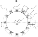
- FIG. 1 and FIG. 2 are schematic block diagrams of main structural examples of the nucleic acid analyzer of FIG. 1 and FIG.
- FIG. 5 is a flowchart showing an example of processing contents of the analysis processing unit in FIG.
- the figure which shows an example of each detection signal obtained by a fluorescence detector and a scattered light detector The figure which shows an example at the time of providing an output value based on each detection signal obtained by a fluorescence detector and a scattered light detector
- the figure showing an example of the time transition of each detection signal when there is no increase in blind fluorescent substance during measurement A figure showing an example of the time transition of each detection signal when there is an increase in blind fluorescent substance during measurement
- the constituent elements are not necessarily indispensable unless otherwise specified and apparently essential in principle. Needless to say.
- the shapes, positional relationships, etc. of the components, etc. when referring to the shapes, positional relationships, etc. of the components, etc., the shapes are substantially the same unless otherwise specified, or otherwise apparent in principle. And the like are included. The same applies to the above numerical values and ranges.
- Embodiment 1 of the present invention will be described with reference to FIG.
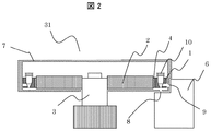
- FIG. 2 is a cross-sectional view illustrating a configuration example between A-A ′ in FIG. 1.
- a plurality of temperature control blocks 1 (12 in this example) are arranged around the center axis of the carousel 2 along the outer periphery, and rotate around the rotation axis 3.
- Peltier elements 4 are arranged between the plurality of temperature control blocks 1 and the carousel 2, respectively.
- the temperature of the temperature control block 1 is adjusted by controlling the Peltier element 4 while monitoring the temperature with a temperature sensor 5 mounted in the temperature control block 1.
- a pair of Peltier elements 4 and temperature sensors 5 corresponding to each of the plurality of temperature control blocks 1 the temperatures of the plurality of temperature control blocks 1 are independently adjusted.
- a photometer 6 is disposed on the outer periphery of the carousel 2.
- two photometers 6 using light of different wavelengths are shown, but one or three or more photometers 6 may be arranged on the outer periphery of the carousel 2. Since all the temperature control blocks 1 move on the same circumference by rotational drive, the relative positions of the photometer 6 and the temperature control block 1 when passing in front of the photometer 6 are the same in all the temperature control blocks 1. become.
- the plurality of temperature control blocks 1 are covered with a shielding plate 7 including the carousel 2 in order to reduce optical disturbance when analyzed by the photometer 6.
- a tube (reaction vessel) 10 containing a reaction solution (sample) in which a reagent or the like is mixed with nucleic acid is held by a temperature control block (holding member) 1.
- All temperature control blocks 1 are provided with an excitation light irradiation window 8 for receiving excitation light from the photometer 6 and a fluorescence detection window 9 for the photometer 6 to capture fluorescence.
- the excitation light irradiation window 8 is arranged on the lower surface side of the temperature control block 1 and the fluorescence detection window 9 is arranged on the side surface side of the temperature control block 1, the arrangement of the windows can be freely set according to the structure of the photometer. It is possible to set.
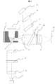
- FIG. 3 is a schematic diagram illustrating a detailed configuration example of a photometer in the nucleic acid analyzer of FIGS. 1 and 2.
- excitation light emitted from a light source LED (Light Emitting Diode) 11 passes through a lens 12 to become parallel light, and needs to pass through a first wavelength selection filter 13. Only the correct wavelength component is extracted. The light that has passed through the first wavelength selection filter 13 is collected by the lens 14 and enters the excitation light irradiation window 8 of the temperature control block (holding member) 1.
- a light source LED Light Emitting Diode
- a tube (reaction vessel) 10 containing a reaction solution (sample) in which a reagent or the like is mixed with nucleic acid is held.
- the excitation light collected by the lens 14 is irradiated to the temperature control block 1 in a state where the tube 10 is held, the fluorescence is emitted from the fluorescent component of the reaction solution in the tube 10 in response to the excitation light.
- the reaction liquid in the tube contains a scattered light component
- the scattered light is emitted from the scattered component in response to the excitation light.
- the fluorescence and scattered light emitted from the fluorescence detection window 9 of the temperature control block 1 are converted into parallel light again by the lens 15.
- the scattered light detector 19 is composed of, for example, a photoelectric conversion diode (PD).
- the remaining light that has passed through the optical splitter 16 passes through the third wavelength selection filter 20 and only the necessary wavelength components are extracted.
- the light that has passed through the third wavelength selection filter 20 is collected by the lens 21 and enters the fluorescence detector (first detector) 22.
- the fluorescence detector 22 is composed of, for example, a photoelectric conversion diode (PD).
- the LED 11 that is a light source always emits excitation light
- the scattered light detector 19 and the fluorescence detector 22 always perform detection.
- the light detected by the scattered light detector 19 and the fluorescence detector 22 generates a detection signal (current or voltage) corresponding to the intensity of the light, and the detection signal is A / D converted through a signal amplification circuit, It is transmitted to the signal processing unit 27.
- the load on the nucleic acid analyzer 31 is heavy, so the nucleic acid analyzer 31 actually triggers just before the temperature control block 1 passes in front of the photometer 6.
- the control for stopping the acquisition of the detection signal is performed immediately after passing.
- a detection signal as shown in FIG. 4 is typically obtained.
- FIG. 4 is a diagram showing an example of temporal transition of each detection signal obtained when analyzing the nucleic acid in the scattered light detector 19 and the fluorescence detector 22 of FIG.
- the detection signals from the scattered light detector 19 and the fluorescence detector 22 become a signal having a mountain waveform over time, and the center line of the temperature control block 1 to be measured passes through the optical axis of the LED 11 of the photometer 6. Peak at the moment you do.
- the detection signal from the scattered light detector 19 is hidden by electrical noise and shows a substantially constant value as shown in FIG.
- nucleic acid analyzers in order to reduce the influence of electrical noise contained in the detection signal, an approximation curve is obtained by curve fitting the detection signal waveform according to a certain rule, and the peak value of the approximation curve is obtained.
- the nucleic acid is analyzed by observing the change.
- FIG. 5 is a schematic block diagram showing an example of a main configuration in terms of the functions of the nucleic acid analyzer of FIGS. 1 and 2.
- a nucleic acid analyzer 31 shown in FIG. 5 includes an analysis processing unit 36 that performs control and the like in addition to the plurality of temperature control blocks 1, the carousel 2, and the photometer 6 described above.
- the analysis processing unit 36 is mainly configured by a computer system or the like, and is mainly a temperature processing unit 38 that adjusts the temperature of each temperature control block 1 based on a predetermined processing sequence, and a rotation that performs rotation control of the carousel 2.
- a processing unit 39 and a signal processing unit 27 for controlling the photometer 6 and the like are included.
- the signal processing unit 27 processes a signal obtained by each detector such as the fluorescence detector 22 and the scattered light detector 19 in the photometer 6. Further, the result of the analysis processing unit 36 is displayed on the display unit 40.
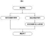
- FIG. 6 is a flowchart showing an example of processing contents of the analysis processing unit 36 in FIG.
- the analysis processing unit 36 is activated, for example, immediately after the nucleic acid analyzer 31 is turned on, and executes the process of FIG. 6 immediately after the start of measurement.
- the analysis processing unit 36 includes an LED (light source) 11 in the photometer 6 and a temperature control block (holding member) 1 in a state where the tube (reaction vessel) 10 shown in FIG. Irradiate excitation light toward
- the light source is unstable immediately after lighting, and may be irradiated in advance.
- what is necessary is just to irradiate LED (light source) 11 previously also when letting the temperature control block 1 pass.
- the fluorescence detector 22 is made to detect the intensity of the fluorescence emitted from the tube (reaction vessel) 10. Further, the scattered light detector 19 detects the intensity of the scattered light generated from the tube (reaction vessel) 10.
- the scattered light may be generated not only in the blind fluorescent material such as bubbles and dust in the tube (reaction vessel) 10 but also in various other places.
- the signal processing unit 37 of the analysis processing unit 36 detects the presence / absence of a blind fluorescent substance based on the detected fluorescence intensity and scattered light intensity.
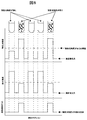
- FIG. 7 is a diagram illustrating an example of each detection signal obtained by the fluorescence detector and the scattered light detector.
- the detection signal from the fluorescence detector 19 includes a fluorescent material and shows a value greater than or equal to a certain value as compared to the background when the blind fluorescent material is not mixed.
- the scattered light detector 22 is detected when a blind fluorescent material is mixed.
- the detection value of fluorescence may be reduced due to the mixing of the blind fluorescent substance as compared with the case where it is not mixed.
- the fluorescence intensity and the scattered light intensity are constant for the sake of explanation, but the fluorescence intensity and the scattered light intensity change depending on the content of the fluorescent substance or the blind fluorescent substance or the progress of the PCR cycle. There is.
- the diagnosis is performed with the light emission power of the LED 11 set to the same level as in FIG. 4, but depending on the case, the light emission power of the LED 11 is increased to reduce the scattered light. You may detect the presence or absence of a blind fluorescent substance in the increased state.
- FIG. 8 is a diagram showing an example of a case where a threshold value is provided for the detection signal obtained by the scattered light detector.
- a threshold value is set in advance in the level of the scattered light detection signal in FIG. 7, and when this threshold value is exceeded, it is determined that the blind fluorescent material is mixed, and an alarm is output to the display unit 40. Then, it can be easily determined that the blind fluorescent substance is contained in the reaction container in the tube.
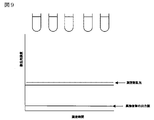
- FIG. 9 is a diagram showing an example of the temporal transition of each detection signal when there is no blind fluorescent substance during measurement, or when the amount of blind fluorescent substance is very small and the blind fluorescent substance does not increase by PCR. In such a case, the scattered light intensity does not increase, and an output value indicating the presence or absence of foreign matter is not detected.
- FIG. 10 is a diagram showing an example of temporal transition of each detection signal when there is a blind fluorescent substance during measurement and the blind fluorescent substance increases by PCR.
- the blind fluorescent material contained in the reaction vessel increases, the scattered light intensity increases.
- an output signal that exceeds this threshold value and is determined to contain a blind fluorescent substance can be obtained.
- FIG. 11 is a top view showing a schematic configuration example of the nucleic acid analyzer according to the present embodiment.
- the nucleic acid analyzer 32 in FIG. 11 is a nucleic acid extraction unit 33 that extracts nucleic acid from a specimen, a reagent mixing unit 34 that dispenses and mixes reagents into the extracted nucleic acid, and the temperature of the mixed reaction solution to control fluorescence. And a nucleic acid analysis unit 35 for detecting.
- the nucleic acid extraction unit 33 is composed of a sample erection unit 41, a centrifuge unit 42, a retraction chamber 43, a tube erection unit 44, an extraction reagent storage 45, a consumables storage 46, and the like. It is responsible for removing components and extracting only the nucleic acids required for analysis.
- the reagent mixing unit 34 includes an analysis reagent storage 47, a consumable storage 48, a mixing unit 49, and the like. Although not described in detail, the reagent for analysis is mixed with the nucleic acid extracted by the nucleic acid extraction unit 33. Take on the function.
- the configuration of the nucleic acid analysis unit 35 is the same as that of the nucleic acid analyzer 31 shown in FIG. The transfer of the tubes between the units is performed by the robot arm 50.
- the person performing the analysis starts up the nucleic acid analyzer 32, sets consumables such as specimens, reagents, and tubes, and starts analysis.
- the analysis processing unit indicates that the result is that the blind fluorescent substance is mixed
- the user can confirm that there is no contamination with a blind fluorescent substance before the pretreatment for analysis (specifically, before mixing the reagents, more preferably before extracting the nucleic acid), The sample is not wasted.
- the nucleic acid extraction unit 33, the reagent mixing unit 34, and the nucleic acid analysis unit 35 are configured by different devices, there may occur a situation in which the reagents are already mixed.
- the present invention made by the present inventor has been specifically described based on the embodiment.
- the present invention is not limited to the embodiment, and various modifications can be made without departing from the scope of the invention.
- the above-described embodiment has been described in detail for easy understanding of the present invention, and is not necessarily limited to one having all the configurations described.
- a part of the configuration of one embodiment can be replaced with the configuration of another embodiment, and the configuration of another embodiment can be added to the configuration of one embodiment. .
- the nucleic acid analyzer which is a particularly useful application example of the apparatus diagnosis method according to the present embodiment has been described.
- the present invention is not necessarily limited to the nucleic acid analyzer.
- the same effect can be applied to any apparatus that sets a reaction vessel on a holding member and analyzes a sample in the reaction vessel using a photometer. May be obtained.
Landscapes
- Health & Medical Sciences (AREA)
- Chemical & Material Sciences (AREA)
- Life Sciences & Earth Sciences (AREA)
- General Health & Medical Sciences (AREA)
- Analytical Chemistry (AREA)
- Biochemistry (AREA)
- Immunology (AREA)
- General Physics & Mathematics (AREA)
- Pathology (AREA)
- Engineering & Computer Science (AREA)
- Bioinformatics & Cheminformatics (AREA)
- Physics & Mathematics (AREA)
- Wood Science & Technology (AREA)
- Organic Chemistry (AREA)
- Biotechnology (AREA)
- Zoology (AREA)
- Medicinal Chemistry (AREA)
- Sustainable Development (AREA)
- Microbiology (AREA)
- Biomedical Technology (AREA)
- General Engineering & Computer Science (AREA)
- Genetics & Genomics (AREA)
- Nuclear Medicine, Radiotherapy & Molecular Imaging (AREA)
- Investigating, Analyzing Materials By Fluorescence Or Luminescence (AREA)
- Investigating Or Analysing Materials By Optical Means (AREA)
- Apparatus Associated With Microorganisms And Enzymes (AREA)
- Investigating Or Analysing Biological Materials (AREA)
- Automatic Analysis And Handling Materials Therefor (AREA)
Abstract
反応容器中の混入物等を迅速に検出することが可能な核酸分析装置を提供する。試料を入れた反応容器を保持できる保持部材と、保持部材の所定の位置に光を照射する光源と、光源からの光の照射に応じて保持部材の所定の位置から放射される蛍光を検出する第1検出器と、光源からの光の照射に応じて保持部材の所定の位置から放射される散乱光を検出する第2検出器と、を有することを特徴とする核酸分析装置において、当該散乱光の強度に基づいて反応容器中の試料の判定を行う。
Description
本発明は、分析装置およびその分析方法に関し、例えば、生物学的試料に含まれる核酸を増幅することによって生物学的試料を分析するための分析装置およびその分析方法に関する。
血液、血漿、組織片などの生物学的試料に含まれる核酸の分析は、生物学、生化学、医学などの学術研究ばかりでなく、診断、農作物の品種改良、食品検査といった産業など多岐の分野で行われている。核酸の分析方法としてもっとも広く普及している方法は、PCR(Polymerase Chain Reaction)と呼ばれる、分析したい領域の核酸を塩基配列特異的に増幅させる技術である。PCRでは、核酸とそれを増幅させるための試薬を含む反応液を、95℃程度に加熱して核酸を熱変性させ、その後60℃程度まで冷却して核酸のアニーリングと伸長反応を進めるというサイクルが30~40回繰り返される。反応の進行に伴う核酸の増幅を検出する方式として、多くの場合、PCR生成物量に依存して蛍光強度が変化する蛍光標識を反応液に混合し、励起光を照射して、蛍光標識から放射される蛍光強度を測定する方式が用いられる。
PCRは数百万ものDNAコピーを合成できる一方で、混入物に非常に敏感なためごく微量の鋳型DNAから反応を開始する場合、反応系の外から入ってくる物質のコンタミネーションが問題となっている。
特許文献1には、回転軸線回りに回転可能なカローセルと、カローセルの円周状の縁に沿って保持された複数の反応容器と、反応容器に励起光を照射する光源と該反応容器内の反応液からの蛍光を検出する検出素子とを有する少なくとも1個の検出器と、を有する分析装置に関しての記載がある。
特許文献2では、自動分析装置上での散乱光測定における気泡・ゴミの影響を低減する方法について記載されている。
PCR法を用いた際、核酸とそれを増幅させるための試薬を含む反応液中に気泡やゴミが存在すると、分析したい領域の核酸を効率的に増幅できないという問題が生じる。さらに、反応液に励起光を照射して、蛍光標識から放射される蛍光強度を測定する際に、反応液中に気泡やゴミなどの外乱物質が存在するとノイズとなってしまい効果的に蛍光強度を測定できないという問題が生じる。
例えば、特許文献1にはPCR法を用いて反応液を増幅させる方法が記載されているが、ノイズに関する記載はない。さらに、特許文献2には自動分析装置上での散乱光測定における気泡・ゴミの影響についての記載はあるが、自動分析装置とは異なる方法で検出する核酸分析装置では、そのまま適用できない。
本発明は、このようなことを鑑みてなされたものであり、その目的の一つは、反応液中のコンタミネーションを迅速に検出することが可能な核酸分析装置およびその核酸分析方法を提供することにある。
本願において開示される発明のうち、代表的な実施の形態の概要を簡単に説明すれば、次のとおりである。試料を入れた反応容器を保持できる保持部材と、保持部材の所定の位置に光を照射する光源と、光源からの光の照射に応じて保持部材の所定の位置から放射される蛍光を検出する第1検出器と、光源からの光の照射に応じて保持部材の所定の位置から放射される散乱光を検出する第2検出器と、を有することを特徴とする核酸分析装置。
本願において開示される発明のうち、代表的な実施の形態によって得られる効果を簡単に説明すると、核酸分析装置において、分析の異常等を迅速に検出することが可能になる。
以下の実施の形態においては便宜上その必要があるときは、複数のセクションまたは実施の形態に分割して説明するが、特に明示した場合を除き、それらは互いに無関係なものではなく、一方は他方の一部または全部の変形例、詳細、補足説明等の関係にある。また、以下の実施の形態において、要素の数等(個数、数値、量、範囲等を含む)に言及する場合、特に明示した場合および原理的に明らかに特定の数に限定される場合等を除き、その特定の数に限定されるものではなく、特定の数以上でも以下でも良い。
さらに、以下の実施の形態において、その構成要素(要素ステップ等も含む)は、特に明示した場合および原理的に明らかに必須であると考えられる場合等を除き、必ずしも必須のものではないことは言うまでもない。同様に、以下の実施の形態において、構成要素等の形状、位置関係等に言及するときは、特に明示した場合および原理的に明らかにそうでないと考えられる場合等を除き、実質的にその形状等に近似または類似するもの等を含むものとする。このことは、上記数値および範囲についても同様である。
以下、本発明の実施の形態を図面に基づいて詳細に説明する。なお、実施の形態を説明するための全図において、同一の部材には原則として同一の符号を付し、その繰り返しの説明は省略する。
図1を用いて、本発明の実施形態1について説明する。本発明の実施の形態1による核酸分析装置において、その主要部の構成例を示す上面図である。図2は、図1のA-A’間の構成例を示す断面図である。図1および図2の核酸分析装置9において、温調ブロック1は、カローセル2の中心軸周りで外周に沿って複数個(この例では12個)配置されており、回転軸3を中心に回転駆動される。複数の温調ブロック1とカローセル2との間にはそれぞれペルチェ素子4が配置される。温調ブロック1の温度は、温調ブロック1内に搭載された温度センサ5で温度をモニタしながらペルチェ素子4を制御することで調整される。複数の温調ブロック1のそれぞれに対応してペルチェ素子4及び温度センサ5を一組ずつ配置することで、複数の温調ブロック1の温度は、それぞれ独立に調整される。
カローセル2の外周には、光度計6が配置される。ここでは、一例として、それぞれ異なる波長の光を用いる2個の光度計6は示しているが、カローセル2の外周であれば1個あるいは3個以上の光度計6を配置しても構わない。全ての温調ブロック1は回転駆動により同一円周上を動くため、光度計6の前を通過する際の光度計6と温調ブロック1との相対位置は、全ての温調ブロック1で同じになる。
複数の温調ブロック1は、光度計6で分析する際に光学的な外乱を低減するため、カローセル2を含めて遮蔽板7で覆われている。分析が実施される際には、核酸に試薬などを混ぜた反応液(試料)を含むチューブ(反応容器)10が温調ブロック(保持部材)1で保持される。全ての温調ブロック1には、光度計6から励起光を受けるための励起光照射窓8と、光度計6が蛍光を取り込むための蛍光検出窓9とが設けられる。ここでは、励起光照射窓8を温調ブロック1の下面側に、蛍光検出窓9を温調ブロック1の側面側に配置しているが、光度計の構造に応じて窓の配置は自由に設定することが可能である。
次に、光度計6の詳細な説明を行う。図3は、図1および図2の核酸分析装置における光度計の詳細な構成例を示す模式図である。図3の光度計6において、光源であるLED(Light Emitting Diode、発光ダイオード)11から照射された励起光は、レンズ12を通過して平行光となり、第一波長選択フィルタ13を通過して必要な波長成分だけが取り出される。第一波長選択フィルタ13を通過した光は、レンズ14で集光され、温調ブロック(保持部材)1の励起光照射窓8へ入射する。温調ブロック1では、核酸に試薬などを混ぜた反応液(試料)を含むチューブ(反応容器)10が保持される。レンズ14で集光された励起光がチューブ10を保持した状態の温調ブロック1に照射されると、励起光に反応してチューブ10内の反応液の蛍光成分より蛍光を放射する。さらにチューブ内の反応液に散乱光成分が含まれている場合は励起光に反応して散乱成分より散乱光を放射する。さらに温調ブロック1の蛍光検出窓9から放射された蛍光および散乱光は、レンズ15で再び平行光となる。レンズ15を通過した光の一部は、光スプリッタ16で反射し、第二波長選択フィルタ17を通過して必要な波長成分だけが取り出される。第二波長選択フィルタ17を通過した光は、レンズ18で集光され、散乱光検出器(第2検出器)19へ入射する。散乱光検出器19は、例えば、光電変換用ダイオード(PD)等で構成される。
一方、光スプリッタ16を通過した残りの光は、第三波長選択フィルタ20を通過して必要な波長成分だけが取り出される。第三波長選択フィルタ20を通過した光は、レンズ21で集光され、蛍光検出器(第1検出器)22へ入射する。蛍光検出器22は、例えば、光電変換用ダイオード(PD)等で構成される。
例えば、光源であるLED11は常に励起光を照射し、散乱光検出器19および蛍光検出器22は常に検出を行っている。散乱光検出器19および蛍光検出器22で検出された光は、光の強度に応じた検出信号(電流または電圧)を生成し、当該検出信号は、信号増幅回路を経てA/D変換され、信号処理部27へ伝送される。ただし、全ての検出信号を常に信号処理すると、核酸分析装置31の負担が大きいため、核酸分析装置31は、実際には、温調ブロック1が光度計6の前を通過する直前にトリガをかけ、通過した直後に検出信号の取得を止める制御を行う。
このような制御によって核酸の分析を行った場合、典型的には図4に示すような検出信号が得られる。
図4は、図3の散乱光検出器19および蛍光検出器22において、核酸を分析する際に得られる各検出信号の時間的推移の一例を示す図である。一般に、散乱光検出器19および蛍光検出器22による検出信号は、経時的に山なりの波形を持つ信号となり、計測対象の温調ブロック1の中心線が光度計6のLED11の光軸を通過する瞬間にピークを迎える。しかし、散乱光が小さい場合には、散乱光検出器19による検出信号は電気的なノイズに隠れ、図4に示すようにほぼ一定の値を示す。多くの核酸分析装置では、検出信号に含まれる電気的なノイズの影響を低減するために、検出信号の波形をある規則に従ってカーブフィッティングして近似曲線を求め、その近似曲線のピークの値を取得し、その変化を観測することで核酸の分析が行われる。
次に、以上のように構成した核酸分析装置において、反応容器中の気泡やゴミ等の盲蛍光物質の混入有無を検出するための方法について説明する。
図5は、図1および図2の核酸分析装置において、その機能面での主な構成例を示す概略ブロック図である。図5に示す核酸分析装置31は、前述した複数の温調ブロック1、カローセル2および光度計6に加えて、これらの制御等を行う分析処理部36を備える。分析処理部36は、主にコンピュータシステム等によって構成され、主に、所定の処理シーケンスに基づいて、各温調ブロック1の温度調整を行う温度処理部38や、カローセル2の回転制御を行う回転処理部39や、光度計6の制御等を行う信号処理部27を有する。信号処理部27は、光度計6内の蛍光検出器22や散乱光検出器19等の各検出器によって得られた信号を処理する。さらに、分析処理部36の結果等を表示部40に表示する。
図6は、図5における分析処理部36の処理内容の一例を示すフロー図である。分析処理部36は、例えば、核酸分析装置31の電源投入直後に起動され、測定開始直後に図6の処理を実行する。まず、分析処理部36は、光度計6内のLED(光源)11を、光度計6上に図3に示したチューブ(反応容器)10が保持された状態の温調ブロック(保持部材)1に向けて励起光を照射させる。一般に光源は、点灯直後は不安定なため、予め照射させておいても構わない。また、温調ブロック1を通過させる場合も、LED(光源)11は予め照射させておけばよい。
次いで、蛍光検出器22に、チューブ(反応容器)10から放射された蛍光の強度を検出させる。さらに、散乱光検出器19はチューブ(反応容器)10から生じる散乱光の強度を検出させる。ここで、散乱光は、チューブ(反応容器)10内の例えば気泡やゴミ等の盲蛍光物質のみならず、それ以外の様々な箇所で生じ得る。
続いて、分析処理部36の信号処理部37は、検出された蛍光の強度や、散乱光の強度に基づいて、盲蛍光物質の混入の有無を検出する。
図7は、蛍光検出器および散乱光検出器によって得られる各検出信号の一例を示す図である。蛍光検出器19からの検出信号は、蛍光物質が含まれ、かつ盲蛍光物質が混入していない場合は、バックブラウンドと比較して一定以上の値を示す。一方、散乱光検出器22は盲蛍光物質が混入している場合に検出される。さらに、盲蛍光物質の混入により、混入していない場合と比較すると蛍光の検出値が減少する場合もある。なお、図7の例は、説明のために蛍光強度と散乱光強度を一定としているが、蛍光物質や盲蛍光物質の含量、あるいはPCRサイクルの進行によって、蛍光強度と散乱光強度は変化する場合がある。また、装置の実使用条件を想定して、LED11の発光パワーを図4の場合と同レベルに設定した状態で診断を行っているが、場合によっては、LED11の発光パワーを増やし、散乱光を増やした状態で盲蛍光物質の混入の有無を検出してもよい。
図8は、散乱光検出器によって得られる検出信号に閾値を設けた場合の一例を示す図である。図7の場合と同様に、盲蛍光物質が混入している場合は、散乱光が増加する。この際に、図7における散乱光検出信号のレベルに予め閾値を設けておき、この閾値を上回った場合には盲蛍光物質が混入していると判定し、表示部40にアラームを出すようにしておけば、チューブ内の反応容器に盲蛍光物質が入っていることを容易に判断可能となる。
図9は測定中に盲蛍光物質がない、あるいは盲蛍光物質が極めて微量でPCRによって盲蛍光物質が増加しない場合の各検出信号の時間的推移の一例を表す図である。このような場合は、散乱光強度は増加せず、さらに、異物の有無の出力値は検出されない。
一方、図10は測定中に盲蛍光物質があり、PCRによって盲蛍光物質が増加する場合の各検出信号の時間的推移の一例を表す図である。反応容器中に含まれる盲蛍光物質が増加すると、散乱光強度は増加する。さらに、散乱光検出信号のレベルに予め閾値を設けておくことによって、この閾値を上回り、盲蛍光物質が混入していると判定される出力信号が得られる。
図11は、本実施例による核酸分析装置において、その概略的な構成例を示す上面図である。図11の核酸分析装置32は、検体から核酸を抽出する核酸抽出ユニット33と、抽出した核酸に試薬を分注し、混合する試薬混合ユニット34と、混合後の反応液を温調して蛍光を検出する核酸分析ユニット35とを備える。
核酸抽出ユニット33は、検体架設部41、遠心部42、退避室43、チューブ架設部44、抽出試薬保管庫45、消耗品保管庫46などから構成され、詳しい説明は省略するが、検体から不要成分を取り除き、分析に必要な核酸だけを抽出する機能を担う。試薬混合ユニット34は、分析試薬保管庫47、消耗品保管庫48、混合部49などから構成され、詳しい説明は省略するが、核酸抽出ユニット33で抽出された核酸に分析用の試薬を混合する機能を担う。核酸分析ユニット35の構成は、図1に示した核酸分析装置31と同じであり、最終工程となる核酸を分析する機能を担う。各ユニット間のチューブの搬送は、ロボットアーム50によって行われる。
分析の実行者は、核酸分析装置32を立ち上げ、検体、試薬、チューブなどの消耗品をセットし、分析を開始する。この際に、分析処理部において仮に盲蛍光物質が混入していた結果が示された場合には、盲蛍光物質が混入していた検体と同様の処理により試薬の調製を行った検体グループに対して分析用の前処理を施す前(具体的には試薬を混合する前であり、より望ましくは核酸を抽出する前)にユーザーにて盲蛍光物質の混入がないかを確認することができ、検体が無駄にならなくて済む。比較例として、核酸抽出ユニット33、試薬混合ユニット34および核酸分析ユニット35がそれぞれ別の装置によって構成されるような場合、既に試薬の混合が行われてしまっているような事態が生じ得る。
以上、本発明者によってなされた発明を実施の形態に基づき具体的に説明したが、本発明は前記実施の形態に限定されるものではなく、その要旨を逸脱しない範囲で種々変更可能である。例えば、前述した実施の形態は、本発明を分かり易く説明するために詳細に説明したものであり、必ずしも説明した全ての構成を備えるものに限定されるものではない。また、ある実施の形態の構成の一部を他の実施の形態の構成に置き換えることが可能であり、また、ある実施の形態の構成に他の実施の形態の構成を加えることも可能である。また、各実施の形態の構成の一部について、他の構成の追加・削除・置換をすることが可能である。
例えば、これまでの説明では、本実施の形態による装置診断方法の特に有益な適用例となる核酸分析装置について説明を行った。ただし、必ずしも核酸分析装置に限定されるものではなく、反応容器を保持部材にセットし、光度計を用いて反応容器内の試料を分析する装置であれば、同様に適用して、同様の効果が得られる場合がある。
1 温調ブロック
2 カローセル
3 回転軸
4 ペルチェ素子
5 温度センサ
6 光度計
7 遮蔽板
8 励起光照射窓
9 蛍光検出窓
10 チューブ
11 LED
12,14,15,18,21 レンズ
13 第一波長選択フィルタ
15 励起光モニタ検出器(第2検出器)
16 光スプリッタ
17 第二波長選択フィルタ
19 散乱光検出器(第2検出器)
20 第三波長選択フィルタ
22 蛍光検出器(第1検出器)
31,32 核酸分析装置
33 核酸抽出ユニット
34 試薬混合ユニット
35 核酸分析ユニット
36 分析処理部
37 信号処理部
38 温度処理部
39 回転処理部
40 表示部
41 検体架設部
42 遠心部
43 退避室
44 チューブ架設部
45 抽出試薬保管庫
46,48 消耗品保管庫
47 分析試薬保管庫
49 混合部
50 ロボットアーム
2 カローセル
3 回転軸
4 ペルチェ素子
5 温度センサ
6 光度計
7 遮蔽板
8 励起光照射窓
9 蛍光検出窓
10 チューブ
11 LED
12,14,15,18,21 レンズ
13 第一波長選択フィルタ
15 励起光モニタ検出器(第2検出器)
16 光スプリッタ
17 第二波長選択フィルタ
19 散乱光検出器(第2検出器)
20 第三波長選択フィルタ
22 蛍光検出器(第1検出器)
31,32 核酸分析装置
33 核酸抽出ユニット
34 試薬混合ユニット
35 核酸分析ユニット
36 分析処理部
37 信号処理部
38 温度処理部
39 回転処理部
40 表示部
41 検体架設部
42 遠心部
43 退避室
44 チューブ架設部
45 抽出試薬保管庫
46,48 消耗品保管庫
47 分析試薬保管庫
49 混合部
50 ロボットアーム
Claims (10)
- 試料を入れた反応容器を保持できる保持部材と、
保持部材の所定の位置に光を照射する光源と、
光源からの光の照射に応じて保持部材の所定の位置から放射される蛍光を検出する第1検出器と、
光源からの光の照射に応じて保持部材の所定の位置から放射される散乱光を検出する第2検出器と、を有することを特徴とする核酸分析装置。 - 請求項1記載の核酸分析装置において、
前記第1検出器と前記第2検出器の検出結果を用いて前記反応容器中の試料を分析する分析処理部を有することを特徴とする分析装置。 - 請求項2記載の核酸分析装置において、
前記分析処理部は、前記第2検出器で検出された散乱光の強度に基づいて前記反応容器中の試料を分析することを特徴とする核酸分析装置。 - 請求項3記載の核酸分析装置において、
前記分析処理部は、前記第2検出器で検出された散乱光の強度が予め定めた基準値よりも高い場合には、前記反応容器中の試料を異常と判断することを特徴とする核酸分析装置。 - 請求項4記載の核酸分析装置において、
さらに前記分析処理部の結果を表示する表示部を有し、
前記表示部は、前記分析処理部は、前記反応容器中の試料を異常と判断した場合にアラームを表示することを特徴とする核酸分析装置。 - 請求項5記載の核酸分析装置において、
前記複数の保持部材は、それぞれ独立に温度調整が可能な機構を備えることを特徴とする核酸分析装置。 - 請求項6記載の核酸分析装置において、
さらに、反応容器内で核酸に試薬を混合して試料を作成する試薬混合ユニットと、
前記試料を分析する分析ユニットと、を有することを特徴とする核酸分析装置。 - 試料を入れた反応容器を保持できる保持部材と、
保持部材の所定の位置に光を照射する光源と、を有する核酸分析装置の検出方法であって、
前記光源から前記反応容器に向かって光を照射し、
前記反応容器から放射される蛍光を検出し、
さらに、前記反応容器から放射される散乱光を検出することを特徴とする核酸分析装置の検出方法。 - 請求項8記載の核酸分析装置の検出方法において、
前記検出された散乱光の強度に基づいて前記試料の診断を行うことを特徴とする核酸分析装置の検出方法。 - 請求項9記載の核酸分析装置の検出方法において、
前記検出された散乱光の強度が予め定めた基準値よりも高い場合には、前記反応容器中の試料を異常と判断することを特徴とする核酸分析装置の検出方法。
Priority Applications (1)
| Application Number | Priority Date | Filing Date | Title |
|---|---|---|---|
| JP2017502048A JP6476275B2 (ja) | 2015-02-27 | 2016-02-10 | 分析装置およびその分析方法 |
Applications Claiming Priority (2)
| Application Number | Priority Date | Filing Date | Title |
|---|---|---|---|
| JP2015-037621 | 2015-02-27 | ||
| JP2015037621 | 2015-02-27 |
Publications (1)
| Publication Number | Publication Date |
|---|---|
| WO2016136464A1 true WO2016136464A1 (ja) | 2016-09-01 |
Family
ID=56789475
Family Applications (1)
| Application Number | Title | Priority Date | Filing Date |
|---|---|---|---|
| PCT/JP2016/053880 Ceased WO2016136464A1 (ja) | 2015-02-27 | 2016-02-10 | 分析装置およびその分析方法 |
Country Status (2)
| Country | Link |
|---|---|
| JP (1) | JP6476275B2 (ja) |
| WO (1) | WO2016136464A1 (ja) |
Cited By (3)
| Publication number | Priority date | Publication date | Assignee | Title |
|---|---|---|---|---|
| JP2018205087A (ja) * | 2017-06-02 | 2018-12-27 | 浜松ホトニクス株式会社 | 光計測装置 |
| CN111747019A (zh) * | 2020-07-03 | 2020-10-09 | 江西奥普照明有限公司 | 一种led灯管的自动检测流水线 |
| CN116075712A (zh) * | 2019-09-10 | 2023-05-05 | 怀亚特技术公司 | 测量样品的动态光散射 |
Citations (5)
| Publication number | Priority date | Publication date | Assignee | Title |
|---|---|---|---|---|
| JPS5723844A (en) * | 1980-07-19 | 1982-02-08 | Chugai Pharmaceut Co Ltd | Method and apparatus for measuring light scattering removed of influence of unnecessary scattered light in solution |
| JPH08240529A (ja) * | 1995-03-02 | 1996-09-17 | Orc Mfg Co Ltd | 液体収納容器内の微小異物の検出装置およびその方法 |
| JP2011149822A (ja) * | 2010-01-21 | 2011-08-04 | Sony Corp | 光学的測定装置及び光学的測定方法 |
| JP2013148590A (ja) * | 2013-04-05 | 2013-08-01 | Hitachi High-Technologies Corp | 核酸分析装置及び核酸分析方法 |
| JP2014021008A (ja) * | 2012-07-20 | 2014-02-03 | Hitachi High-Technologies Corp | 自動分析装置及び自動分析方法 |
Family Cites Families (2)
| Publication number | Priority date | Publication date | Assignee | Title |
|---|---|---|---|---|
| JP4170947B2 (ja) * | 2004-04-09 | 2008-10-22 | 株式会社日立ハイテクノロジーズ | 生体試料成分検出法及びその装置 |
| JP2014143927A (ja) * | 2013-01-28 | 2014-08-14 | Hitachi High-Technologies Corp | 核酸増幅装置および温度調節機能の異常検出方法 |
-
2016
- 2016-02-10 WO PCT/JP2016/053880 patent/WO2016136464A1/ja not_active Ceased
- 2016-02-10 JP JP2017502048A patent/JP6476275B2/ja active Active
Patent Citations (5)
| Publication number | Priority date | Publication date | Assignee | Title |
|---|---|---|---|---|
| JPS5723844A (en) * | 1980-07-19 | 1982-02-08 | Chugai Pharmaceut Co Ltd | Method and apparatus for measuring light scattering removed of influence of unnecessary scattered light in solution |
| JPH08240529A (ja) * | 1995-03-02 | 1996-09-17 | Orc Mfg Co Ltd | 液体収納容器内の微小異物の検出装置およびその方法 |
| JP2011149822A (ja) * | 2010-01-21 | 2011-08-04 | Sony Corp | 光学的測定装置及び光学的測定方法 |
| JP2014021008A (ja) * | 2012-07-20 | 2014-02-03 | Hitachi High-Technologies Corp | 自動分析装置及び自動分析方法 |
| JP2013148590A (ja) * | 2013-04-05 | 2013-08-01 | Hitachi High-Technologies Corp | 核酸分析装置及び核酸分析方法 |
Cited By (5)
| Publication number | Priority date | Publication date | Assignee | Title |
|---|---|---|---|---|
| JP2018205087A (ja) * | 2017-06-02 | 2018-12-27 | 浜松ホトニクス株式会社 | 光計測装置 |
| CN116075712A (zh) * | 2019-09-10 | 2023-05-05 | 怀亚特技术公司 | 测量样品的动态光散射 |
| JP2023541897A (ja) * | 2019-09-10 | 2023-10-04 | ワイアット テクノロジー コーポレイション | 試料の動的光散乱の測定 |
| JP7784419B2 (ja) | 2019-09-10 | 2025-12-11 | ワイアット・テクノロジー・リミテッド・ライアビリティー・カンパニー | 試料の動的光散乱を測定するための装置および方法 |
| CN111747019A (zh) * | 2020-07-03 | 2020-10-09 | 江西奥普照明有限公司 | 一种led灯管的自动检测流水线 |
Also Published As
| Publication number | Publication date |
|---|---|
| JP6476275B2 (ja) | 2019-02-27 |
| JPWO2016136464A1 (ja) | 2017-12-21 |
Similar Documents
| Publication | Publication Date | Title |
|---|---|---|
| US8895296B2 (en) | Analyzer | |
| JP6130917B2 (ja) | 核酸分析装置およびその装置診断方法 | |
| JP4170947B2 (ja) | 生体試料成分検出法及びその装置 | |
| JP6845858B2 (ja) | サンプルを分析し、光信号検出器の性能を監視するシステム及び方法 | |
| JP6476275B2 (ja) | 分析装置およびその分析方法 | |
| JP7401993B2 (ja) | 検査室用機器内の検出ユニットの検出器によって測定された信号光強度を補正する方法 | |
| JP2017123813A (ja) | 検査装置 | |
| JP6286539B2 (ja) | 核酸分析装置、および核酸分析装置の装置診断方法 | |
| JP2017077180A (ja) | 核酸分析装置 | |
| KR102101553B1 (ko) | 바이오센서용 형광 광학 장치 및 시스템 | |
| EP3290905B1 (en) | Signal offset determination and correction | |
| JP5919218B2 (ja) | 核酸分析装置及び核酸分析方法 | |
| JP2013024746A (ja) | 自動分析装置 | |
| JP6720526B2 (ja) | 検査装置 | |
| JPH04125450A (ja) | 分光蛍光光度計 |
Legal Events
| Date | Code | Title | Description |
|---|---|---|---|
| 121 | Ep: the epo has been informed by wipo that ep was designated in this application |
Ref document number: 16755211 Country of ref document: EP Kind code of ref document: A1 |
|
| ENP | Entry into the national phase |
Ref document number: 2017502048 Country of ref document: JP Kind code of ref document: A |
|
| NENP | Non-entry into the national phase |
Ref country code: DE |
|
| 122 | Ep: pct application non-entry in european phase |
Ref document number: 16755211 Country of ref document: EP Kind code of ref document: A1 |