WO2016133211A1 - 窒化珪素ころ、窒化珪素ころの製造方法、および窒化珪素ころの検査方法 - Google Patents
窒化珪素ころ、窒化珪素ころの製造方法、および窒化珪素ころの検査方法 Download PDFInfo
- Publication number
- WO2016133211A1 WO2016133211A1 PCT/JP2016/054938 JP2016054938W WO2016133211A1 WO 2016133211 A1 WO2016133211 A1 WO 2016133211A1 JP 2016054938 W JP2016054938 W JP 2016054938W WO 2016133211 A1 WO2016133211 A1 WO 2016133211A1
- Authority
- WO
- WIPO (PCT)
- Prior art keywords
- silicon nitride
- crowning
- cylindrical body
- roller
- molded body
- Prior art date
- Legal status (The legal status is an assumption and is not a legal conclusion. Google has not performed a legal analysis and makes no representation as to the accuracy of the status listed.)
- Ceased
Links
Images









Classifications
-
- B—PERFORMING OPERATIONS; TRANSPORTING
- B24—GRINDING; POLISHING
- B24B—MACHINES, DEVICES, OR PROCESSES FOR GRINDING OR POLISHING; DRESSING OR CONDITIONING OF ABRADING SURFACES; FEEDING OF GRINDING, POLISHING, OR LAPPING AGENTS
- B24B31/00—Machines or devices designed for polishing or abrading surfaces on work by means of tumbling apparatus or other apparatus in which the work and/or the abrasive material is loose; Accessories therefor
- B24B31/02—Machines or devices designed for polishing or abrading surfaces on work by means of tumbling apparatus or other apparatus in which the work and/or the abrasive material is loose; Accessories therefor involving rotary barrels
-
- C—CHEMISTRY; METALLURGY
- C04—CEMENTS; CONCRETE; ARTIFICIAL STONE; CERAMICS; REFRACTORIES
- C04B—LIME, MAGNESIA; SLAG; CEMENTS; COMPOSITIONS THEREOF, e.g. MORTARS, CONCRETE OR LIKE BUILDING MATERIALS; ARTIFICIAL STONE; CERAMICS; REFRACTORIES; TREATMENT OF NATURAL STONE
- C04B35/00—Shaped ceramic products characterised by their composition; Ceramics compositions; Processing powders of inorganic compounds preparatory to the manufacturing of ceramic products
- C04B35/515—Shaped ceramic products characterised by their composition; Ceramics compositions; Processing powders of inorganic compounds preparatory to the manufacturing of ceramic products based on non-oxide ceramics
- C04B35/58—Shaped ceramic products characterised by their composition; Ceramics compositions; Processing powders of inorganic compounds preparatory to the manufacturing of ceramic products based on non-oxide ceramics based on borides, nitrides, i.e. nitrides, oxynitrides, carbonitrides or oxycarbonitrides or silicides
- C04B35/584—Shaped ceramic products characterised by their composition; Ceramics compositions; Processing powders of inorganic compounds preparatory to the manufacturing of ceramic products based on non-oxide ceramics based on borides, nitrides, i.e. nitrides, oxynitrides, carbonitrides or oxycarbonitrides or silicides based on silicon nitride
-
- F—MECHANICAL ENGINEERING; LIGHTING; HEATING; WEAPONS; BLASTING
- F16—ENGINEERING ELEMENTS AND UNITS; GENERAL MEASURES FOR PRODUCING AND MAINTAINING EFFECTIVE FUNCTIONING OF MACHINES OR INSTALLATIONS; THERMAL INSULATION IN GENERAL
- F16C—SHAFTS; FLEXIBLE SHAFTS; ELEMENTS OR CRANKSHAFT MECHANISMS; ROTARY BODIES OTHER THAN GEARING ELEMENTS; BEARINGS
- F16C33/00—Parts of bearings; Special methods for making bearings or parts thereof
- F16C33/30—Parts of ball or roller bearings
- F16C33/34—Rollers; Needles
Definitions
- the present invention relates to a silicon nitride roller, a method for manufacturing a silicon nitride roller, and a method for inspecting a silicon nitride roller, and particularly, a silicon nitride roller suitable for a rolling element for a bearing, a method for manufacturing a silicon nitride roller, and an inspection of a silicon nitride roller Regarding the method.
- Bearing steel is mainly used as the material of the rolling element for the bearing (bearing), but ceramics is used for applications that require characteristics such as high-speed rotation, insulation, heat resistance, and corrosion resistance.
- silicon nitride (Si 3 N 4 ) having high strength, high toughness, and high hardness, and excellent heat resistance and corrosion resistance is used as a ceramic material for bearings.
- a method for forming a crowning on a roller a method is generally employed in which a workpiece is ground using a diamond grindstone to form a roller to which the shape of the grindstone is transferred.
- a crowning type threaded adjustment wheel having a curvature is used, and the crowning is transferred to the outer diameter of the tapered roller while intentionally changing the position of the tapered roller with respect to the grindstone.
- a method of performing grinding is known (see JP 2010-284775 A (Patent Document 1)).
- the rolling element is a roller
- mirror finishing is performed to mirror at least the outer diameter surface of the roller.
- the present invention has been made to solve the above-described problems.
- the main object of the present invention is to provide a silicon nitride roller having a crowning formed therein and capable of producing a silicon nitride roller having a higher efficiency than in the past and a silicon nitride roller having a crowning formed therein with a higher efficiency than in the past. It is in providing the manufacturing method of.
- the method of manufacturing a silicon nitride roller according to the present invention includes a plurality of cylindrical bodies whose main constituent material is silicon nitride, a plurality of workpieces whose main constituent material is silicon nitride, and a hardness lower than that of the cylindrical body.
- a step of bringing the workpiece into sliding contact includes a plurality of cylindrical bodies whose main constituent material is silicon nitride, a plurality of workpieces whose main constituent material is silicon nitride, and a hardness lower than that of the cylindrical body.
- a silicon nitride roller in which a crowning is formed and which can be manufactured with higher efficiency than before, and a silicon nitride roller in which a silicon nitride roller on which crowning is formed can be manufactured with higher efficiency than in the past can be obtained.
- the manufacturing method of can be provided.
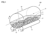
- FIG. 5 is a diagram for explaining the method for manufacturing the silicon nitride roller according to the first embodiment.
- FIG. 5 is a cross-sectional view for explaining a cylindrical body in the method for manufacturing the silicon nitride roller according to the first embodiment.
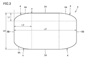
- FIG. 3 is a cross-sectional view for explaining the silicon nitride roller according to the first embodiment.
- 3 is a flowchart of a method for manufacturing the silicon nitride roller according to the first embodiment.
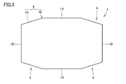
- 6 is a diagram for explaining cut crowning of a cylindrical body in the method for producing a silicon nitride roller according to Embodiment 2.
- FIG. 5 is a flowchart of a method for manufacturing a silicon nitride roller according to Embodiment 2.
- FIG. 6 is a cross-sectional view for explaining a silicon nitride roller according to a second embodiment.
- FIG. 5 is a flowchart of a method for manufacturing a silicon nitride sphere according to Embodiment 3.
- FIG. 10 is a diagram for explaining a spherical body inspection method in the method for manufacturing a silicon nitride spherical body according to Embodiment 3.
- FIG. 10 is a diagram for explaining a modification of the method for inspecting a sphere in the method for producing a silicon nitride sphere according to the third embodiment.
- FIG. 10 is a flowchart of a silicon nitride sphere inspection method according to Embodiment 4; 4 is a graph showing measurement data of a cross-sectional profile of a silicon nitride roller of an example in Example 1.
- 4 is a microscopic image of the surface of the boundary portion between the crowning and the outer diameter surface of the silicon nitride roller of Example 1 in Example 1.
- FIG. 2 is a microscopic image of an outer diameter surface of a silicon nitride roller of an example in Example 1.
- FIG. 2 is a microscopic image of an end face of a silicon nitride roller of an example in Example 1.
- FIG. 2 is a microscopic image of a crowning surface of a silicon nitride roller of an example in Example 1.
- FIG. 2 is a microscopic image of the surface of a boundary portion between a crowning and an outer diameter surface of a silicon nitride roller of a comparative example in Example 1.
- FIG. 2 is a microscopic image of an outer diameter surface of a silicon nitride roller of a comparative example in Example 1.
- FIG. 2 is a microscopic image of an end face of a silicon nitride roller of a comparative example in Example 1.
- FIG. 2 is a microscopic image of a crowning surface of a silicon nitride roller of a comparative example in Example 1.
- FIG. It is a graph which shows the measurement data of the cross-sectional profile of the cylindrical body after the cut crowning process of the Example in Example 2.
- 6 is a graph showing measurement data of a cross-sectional profile of a molded product after ball milling in an example in Example 2.
- 6 is a graph showing measurement data of a cross-sectional profile of a molded article after barrel polishing of a comparative example in Example 2.
- the silicon nitride rollers 5 and 7 are rollers whose main constituent material is silicon nitride, and have an outer diameter surface formed to include a rolling surface and surround a shaft. Further, crowning 4 and 8 are formed at both ends of the outer diameter surface in the extending direction of the shaft, respectively, and the maximum outer shape width is 25 ⁇ m or more in a region where the depth from the roller surface is shallower than 150 ⁇ m. There are no defects.
- the maximum shear stress in the silicon nitride rollers 5 and 7 when the bearing is used is in a region where the depth from the rolling surface is shallower than 150 ⁇ m.
- the area where the acts is included. Therefore, even when such maximum shear stress is applied to the silicon nitride rollers 5 and 7, the occurrence of cracks and the like starting from internal defects is suppressed. That is, in the region where the depth from the surface is shallower than 150 ⁇ m, the silicon nitride rollers 5 and 7 having no defect having a maximum outer width of 25 ⁇ m or more are suitable as rolling elements for bearings.
- a method of manufacturing a silicon nitride roller including the step (S30) of inspecting the molded body described above. Or obtained by carrying out an inspection method for silicon nitride rollers (can be selected).
- the silicon nitride rollers 5 and 7 are silicon nitride rollers whose main constituent material is silicon nitride, which includes a rolling surface and is formed so as to surround the shaft. It has surfaces 5A and 7A, and crowning 4 and 8 are formed at both ends in the extending direction of the axis of the outer diameter surface, respectively.
- the crowning 4, 8 includes a plurality of cylindrical bodies 1 whose main constituent material is silicon nitride, a plurality of workpieces 2 whose main constituent material is silicon nitride, and metal oxide having a lower hardness than the cylindrical body 1. It is formed by mixing the product powder and the dispersion medium 3 to bring the cylindrical body 1 and the workpiece 2 into sliding contact.
- the length L3 (in the extending direction of the axis) of the outer diameter surface (hereinafter, the outer diameter surface on the cross section is referred to as a bus bar)
- the ratio of the length L2 (hereinafter referred to as the crowning length, see FIG. 3) of the crowning 4 and 8 in the extending direction of the above-mentioned axis to the crowning 4, 8 is 9% or more and 25% or less, respectively.
- the crowning length L2 is the length of one crowning 4, 8 formed at one end in the extending direction of the shaft in the extending direction of the shaft.
- the crowning length L2 is the extension of the above-mentioned axis between the end portions a of the outer peripheral surfaces 5A and 7A formed as flat surfaces (portions connected to the crowning 4 formed as curved surfaces) and the end surfaces 5B and 7B.
- the length L3 of the bus bar in the extending direction of the shaft is the axis of the outer diameter surfaces 5A and 7A formed so as to be sandwiched between the crownings 4 and 8 formed at both ends in the extending direction of the shaft. It is the length in the extending direction. That is, the ratio of the crowning length L2 to the length L3 in the extending direction of the axis of the bus is expressed by L2 / L3.
- the silicon nitride rollers 5 and 7 in the present embodiment are thus formed with a long crowning length L2, it is possible to effectively suppress a decrease in roller life due to edge loading. It has been difficult to form such a long crowning length L2 in the conventional method for producing silicon nitride rollers.
- the crowning 4, 8 of the silicon nitride rollers 5, 7 in this example is composed of a plurality of cylindrical bodies 1, a plurality of workpieces 2, a metal oxide powder having a hardness lower than that of the cylindrical body 1, and a dispersion It is formed by mixing the medium 3 and bringing the cylindrical body 1 and the workpiece 2 into sliding contact (by the silicon nitride roller manufacturing method in each embodiment described later). Therefore, the silicon nitride rollers 5 and 7 of the present embodiment can be easily manufactured as compared with the silicon nitride rollers manufactured by the conventional method of manufacturing silicon nitride rollers.
- a method of manufacturing a silicon nitride roller includes a plurality of cylindrical bodies 1 whose main constituent material is silicon nitride (Si 3 N 4 ), and a main constituent material of silicon nitride (Si 3 N 4 ), a step (S 10) of preparing a plurality of workpieces 2, a metal oxide powder having a hardness lower than that of the columnar body 1, and the dispersion medium 3, and a plurality of columnar bodies 1 and a plurality of workpieces.
- the main constituent material of the cylindrical body 1 is silicon nitride, which means that the material constituting 50% by volume or more of the cylindrical body 1 is silicon nitride.
- the cylindrical body 1 includes 50% by volume or more of silicon nitride, for example, 80% by volume or more and 98% by volume or less of silicon nitride.
- making the cylindrical body 1 and the workpiece 2 slidably contact means putting the cylindrical body 1 and the workpiece 2 in a state where they are in contact with each other while sliding on each other. In the sliding contact step (S20), not only the cylindrical body 1 and the workpiece 2 are slid but also the cylindrical bodies 1 can be slid.
- the cylindrical body 1 in the sliding contact step (S20), the cylindrical body 1 is slid with the workpiece 2 or other cylindrical body 1 whose main constituent material is silicon nitride.
- the surface is abraded by the metal oxide powder.
- the cylindrical body 1 causes a chemical reaction with the metal oxide powder on the surface thereof.
- the cylindrical body 1 can be crowned, and the silicon nitride rollers 5 and 7 on which the crownings 4 and 8 are formed can be obtained.
- the unevenness generated on the surface (outer peripheral surface 1A, end surface 1B) of the cylindrical body 1 can be relaxed or removed by the mechanical action and the chemical action.
- the outer peripheral surface 1A, the end surface 1B, and crowning 4, 8 begin to be formed in this step, the surface roughness of the crowning surfaces 4A, 8A can be reduced.
- the entire surface of the cylindrical body 1 can be processed simultaneously by mechanical action and chemical action.
- the cylindrical body 1 is not polished with abrasive grains made of a material harder than itself, and therefore the surface (the outer peripheral surface 1A, the end surface 1B and the crowning surfaces 4A, 8A). ) Can be prevented from being scratched or polished.
- the crowning 4 or 8 is not formed in the preparing step (S10), and the outer peripheral surface 1A and the end surface 1B are not damaged or polished. Even if the cylindrical body 1 on which the concavo-convex portions are formed is prepared, the crowning 4 and 8 are formed by executing the step (S20) of sliding on the cylindrical body 1 and the outer diameter thereof. It is possible to obtain silicon nitride rollers 5 and 7 in which the uneven portions are relaxed and removed on surfaces 5A and 7A and end surfaces 5B and 7B.
- the silicon nitride rollers 5 and 7 have small surface roughness of the outer diameter surfaces 5A and 7A, the end surfaces 5B and 7B, and the crowning surfaces 4A and 8A. For this reason, in the silicon nitride rollers 5 and 7, a decrease in the life of the rollers due to edge load and surface irregularities is suppressed.
- the metal oxide powder is at least one selected from the group consisting of iron oxide (Fe 2 O 3 ), chromium oxide (CrO 2 ), and cerium oxide (CeO 2 ). .
- Fe 2 O 3 , CrO 2 , and CeO 2 are considered to function as a catalyst for oxidizing the surface of silicon nitride. It is considered that the SiO 2 layer can be formed by oxidizing the surface of the cylindrical body 1 by mixing the cylindrical body 1 whose main constituent material is silicon nitride and the metal oxide powder. In particular, there is a probability of rubbing by the metal oxide at the boundary portion between the outer peripheral surface 1A and the end surface 1B formed in a convex shape on the surface of the cylindrical body 1 and the convex portion such as the concave and convex portions such as scratches and polishing marks.
- the SiO 2 layer Since it is high, it is considered that the SiO 2 layer is easily formed. Furthermore, since the convex portion has a high probability of being in sliding contact with the workpiece 2 and the other columnar body 1, it is considered that the SiO 2 layer is easily removed. As a result, the step of sliding contact (S20) can perform crowning on the cylindrical body 1 and relieve irregularities such as scratches and polishing marks formed on the surface of the cylindrical body 1. It can be removed.
- Fe 2 O 3 , CrO 2 , and CeO 2 each have a lower hardness than silicon nitride (Si 3 N 4 ), and the cylindrical body 1 and the work material 2 that are mixed in the sliding contact step (S20).
- Si 3 N 4 silicon nitride
- CeO 2 there is no material having a hardness higher than that of the cylindrical body 1 mainly composed of silicon nitride. Therefore, since it is suppressed that the said uneven part is newly formed in the surface of the cylindrical body 1 in this process (S20), the said uneven part can be relieve
- the metal oxide powder is at least one selected from the group consisting of Fe 2 O 3 , CrO 2 , and CeO 2, so that the crowning 4, 8 And the silicon nitride rollers 5 and 7 in which irregularities such as scratches and polishing marks on the surface are reduced can be manufactured more easily.
- the step (S20) of sliding contact includes the step of storing the cylindrical body 1, the processed material 2, the metal oxide powder, and the dispersion medium 3 in the container 10 (S21).
- the step (S22) of mixing the cylindrical body 1, the processed material 2, the metal oxide powder, and the dispersion medium 3 by moving the container 10 is included.
- the surface of the silicon nitride roller is scratched or polished as compared with the silicon nitride roller obtained by mixing the cylindrical body, the metal oxide powder, and the dispersion medium with a stirring bar or the like without moving the container. Irregularities such as traces and surface roughness Ra value can be reduced.
- the container 10 includes the columnar body 1 while mixing the plurality of columnar bodies 1, the processed material 2, the metal oxide powder, and the dispersion medium 3 accommodated therein.
- the workpiece 2 can be brought into sliding contact, the workpiece 2 can be arbitrarily moved, but is rotated, for example.
- the container 10 is a cylindrical body, and in the mixing step (S22), the cylindrical body 1 and the workpiece 2 are brought into sliding contact with each other by rotating the container 10.
- the cylindrical body 1, the processed material 2, the metal oxide powder, and the dispersion medium 3 that are mainly contained in the container 10 can be mixed uniformly, and the cylindrical body 1 and the processed material 2 are slidably contacted. Can be made.
- the workpiece 2 is a spherical body. If it does in this way, the processing variation with respect to the cylindrical body 1 can be reduced.
- the metal oxide powder is mixed with the cylindrical body 1 and the dispersion medium 3 at a rate of 60 g to 80 g per liter of the dispersion medium 3.
- a method of manufacturing a silicon nitride roller includes a plurality of cylindrical bodies 1 whose main constituent material is silicon nitride, a plurality of workpieces 2 whose main constituent material is silicon nitride, A step of preparing a metal oxide powder having a hardness lower than that of the cylindrical body 1 and the dispersion medium 3 (S10), a plurality of cylindrical bodies 1, a plurality of workpieces 2, a metal oxide powder, and a dispersion medium 3;
- S30 In the step of inspecting the molded body (S30), the molded body is irradiated with light, and the presence of internal defects in the molded body is inspected by detecting light transmitted through at least a part of the molded body.
- the main constituent material of the cylindrical body 1 is silicon nitride, which means that the material constituting 50% by volume or more of the cylindrical body 1 is silicon nitride.
- the cylindrical body 1 includes 50% by volume or more of silicon nitride, for example, 80% by volume or more and 98% by volume or less of silicon nitride.
- making the cylindrical body 1 and the workpiece 2 slidably contact means putting the cylindrical body 1 and the workpiece 2 in a state where they are in contact with each other while sliding on each other. In the sliding contact step (S20), not only the cylindrical body 1 and the workpiece 2 are slid but also the cylindrical bodies 1 can be slid.
- the cylindrical body 1 in the sliding contact step (S20), the cylindrical body 1 is slid with the workpiece 2 or other cylindrical body 1 whose main constituent material is silicon nitride. When contacted, the surface is abraded by the metal oxide powder. At this time, depending on the type of the metal oxide powder, the cylindrical body 1 causes a chemical reaction with the metal oxide powder on the surface thereof. By such mechanical action and chemical action, the cylindrical body 1 can be crowned, and a molded body on which the crownings 4 and 8 are formed can be obtained. Furthermore, at the same time, the degree of the uneven portion generated on the surface (the outer peripheral surface 1A and the end surface 1B) of the cylindrical body 1 is reduced or the uneven portion is removed by the mechanical action and the chemical action.
- the light irradiated to the molded body in the inspection step (S30) is transmitted through the molded body due to the translucency of silicon nitride, and is reflected, absorbed, refracted by internal defects of the molded body.
- the silicon nitride roller manufactured by the conventional method of manufacturing a silicon nitride roller has a large surface roughness, and the region where the internal defect can be evaluated using the translucency of silicon nitride is limited to the region near the surface. It was.
- the molded body obtained by the slidable contact step (S20) has reduced irregularities such as scratches and polishing marks on the surface.
- the reflected light is suppressed from being reflected, absorbed, refracted due to the unevenness on the surface of the molded body. Therefore, among the light irradiated to such a molded body, light (reflected light, transmitted light, refracted light, etc.) transmitted through at least a part of the molded body also travels from the inside of the molded body to the outside. Less susceptible to irregularities on the surface of the molded body. As a result, it is possible to detect reflected light from a deeper position inside the molded body than in the prior art.
- silicon nitride roller 5 in which an internal defect in a deeper region has been inspected with high accuracy as compared with the conventional method for manufacturing a silicon nitride roller. 7 can be manufactured.
- the depth from the rolling surface of the region where the shear stress is maximum in the molded body is about 120 ⁇ m. It was not possible to manufacture silicon nitride rollers that were inspected with high accuracy for internal defects in such deep regions.
- the silicon nitride rollers 5 and 7 in which the internal defects in the region at such a depth are also inspected with high accuracy can be manufactured.
- the step (S30) of inspecting the molded body may be performed by visually inspecting the molded body irradiated with light using a magnifying glass.
- the step (S30) of inspecting the molded body may be performed by capturing a change in reflectance or absorptance from reflected light generated when the molded body is irradiated with laser light. Good.
- a silicon nitride sphere inspection method includes a plurality of cylindrical bodies 1 whose main constituent material is silicon nitride, a plurality of workpieces 2 whose main constituent material is silicon nitride, A molded body formed from the cylindrical body 1 is prepared by mixing the metal oxide powder having a hardness lower than that of the cylindrical body 1 and the dispersion medium 3 and bringing the cylindrical body 1 and the workpiece 2 into sliding contact with each other. And a step of inspecting the molded body for the presence of internal defects by irradiating the molded body with light and detecting light transmitted through at least part of the molded body.
- the light irradiated to such a molded body is on the surface of the molded body. Reflection, absorption, refraction, and the like due to unevenness are suppressed. Therefore, light (reflected light, transmitted light, refracted light, etc.) transmitted through at least a part of the molded body due to the translucency of silicon nitride among the light irradiated on the molded body is reflected on the surface of the molded body. Scattering or the like due to the unevenness is suppressed. As a result, it is possible to detect reflected light from a deeper position inside the molded body than in the prior art.
- the inspection method of the present silicon nitride roller it is possible to inspect internal defects in a deeper region with respect to the silicon nitride roller with higher accuracy than the conventional inspection method of the silicon nitride roller.
- the main constituent material is a plurality of cylindrical body 1 is a silicon nitride (Si 3 N 4), the main constituent material is silicon nitride (Si 3 N 4)
- a plurality of workpieces 2 a metal oxide powder (not shown) having a hardness lower than that of the cylindrical body 1, and a dispersion medium 3 (S 10), and the plurality of cylindrical bodies 1 and the plurality of cylindrical bodies 1
- a metal oxide powder and a dispersion medium 3 are prepared (step (S10)).
- the cylindrical body 1 is prepared, for example, by forming a raw material powder of silicon nitride into a spherical shape, and subjecting the molded body to pressure sintering or normal pressure sintering.
- the cylindrical body 1 may be further polished with abrasive grains having a hardness higher than that of silicon nitride (for example, diamond, green silicon carbide (GC), white alumina (WA), etc.).
- the columnar body 1 contains 50% by volume or more of silicon nitride, for example, 80% by volume or more and 98% by volume or less of silicon nitride.
- the material constituting the cylindrical body 1 may contain, for example, a sintering aid.
- the cylindrical body 1 has an outer peripheral surface 1A and an end surface 1B.
- the outer peripheral surface 1A and the end surface 1B are orthogonal, for example.
- the dimensions (outer diameter, length, etc.) of the cylindrical body 1 may be any size, but are dimensions standardized by, for example, JIS standards and ISO standards as bearing rolling elements.
- this step (S10) a plurality of columnar bodies 1 are prepared. At this time, it is preferable that the plurality of cylindrical bodies 1 have substantially the same dimensions.
- the cylindrical body 1 does not have to be provided in a complete cylindrical shape as long as it has an axis and the outer peripheral surface 1A is formed so as to surround the axis.
- the material constituting the workpiece 2 is mainly composed of silicon nitride, similarly to the material constituting the cylindrical body 1 that is a workpiece. That is, the workpiece 2 contains 50% by volume or more of silicon nitride, for example, 80% by volume or more and 98% by volume or less of silicon nitride.
- the material constituting the processed material 2 may include, for example, a sintering aid.
- the processed material 2 may have an arbitrary shape, but is preferably provided as a spherical body from the viewpoint of reducing processing variation with respect to the cylindrical body 1.
- the plurality of workpieces 2 may have different characteristics (silicon nitride content, shape, dimensions, etc.), but from the viewpoint of reducing processing variation with respect to the cylindrical body 1, the same shape and equivalent dimensions are provided. It is preferable to have.
- the processed material 2 is prepared by, for example, forming a silicon nitride raw material powder into a spherical shape, and subjecting the molded body to pressure sintering or normal pressure sintering. Further, the processed material 2 can be reused from the processed material 2 used in the method for manufacturing the silicon nitride roller according to the first embodiment.
- the cylindrical body 1 and the processed material 2 may be the same or different in content of silicon nitride, other contained elements, etc. as long as the main constituent material is silicon nitride. Also good. Further, the dimension (outer diameter, etc.) of the workpiece 2 may be an arbitrary size as long as it can be brought into sliding contact with the cylindrical body 1, and may be larger than the cylindrical body 1. Preferably, the dimension of the workpiece 2 is smaller than the dimension of the cylindrical body 1.
- the metal oxide powder is a powder of a metal oxide having a hardness lower than that of silicon nitride, which is a main constituent material of the cylindrical body 1.
- the metal oxide powder has a lower hardness than the cylindrical body 1.
- the metal oxide powder is, for example, at least one selected from the group consisting of iron oxide (Fe 2 O 3 ), chromium oxide (CrO 2 ), and cerium oxide (CeO 2 ).
- the particle diameter (particle size) of the metal oxide powder may be any size generally handled as abrasive grains or loose abrasive grains, for example, but is preferably 1 ⁇ m or less. Note that the particle size distribution (particle size distribution) of the metal oxide powder need not be strictly limited because the metal oxide powder has a lower hardness than the cylindrical body 1.
- the dispersion medium 3 is a liquid in which the metal oxide powder is suspended.
- the dispersion medium 3 can be any liquid as long as the metal oxide powder can be suspended.
- the dispersion medium 3 is a liquid having an OH group, such as water or alcohol.
- the cylindrical body 1 and the workpiece 2 are brought into sliding contact with each other by mixing the plurality of cylindrical bodies 1, the metal oxide powder, and the dispersion medium 3 (step (S20)).
- step (S20) first, the plurality of cylindrical bodies 1, the plurality of workpieces 2, the metal oxide powder, and the dispersion medium 3 prepared in the previous step (S10) are accommodated in the container 10 (step (step (S21)).
- the container 10 only needs to have an arbitrary shape and dimensions as long as it can accommodate a predetermined amount of the cylindrical body 1, the processed material 2, the metal oxide powder, and the dispersion medium 3.
- the container 10 has, for example, a cylindrical shape with a diameter of 200 mm and an axial length of 200 mm, and the material constituting the container 10 is polyethylene.
- such a container 10 for example, 20 cylindrical bodies 1 having an outer diameter of 10.3188 mm (13/32 inches), 300 workpieces 2, 100 g of metal oxide powder, and dispersion medium 3 1.5L can be accommodated. At this time, it is preferable that the dispersion medium 3 and the metal oxide powder are accommodated in the container 10 and mixed at a rate of 60 g or more and 80 g or less per liter of the dispersion medium 3.
- the number of workpieces 2 accommodated in the container 10 is preferably equal to or greater than the number of columnar bodies 1, for example, so that the columnar bodies 1 and the workpieces 2 are in sliding contact. Probability can be increased.
- the container 10 is rotatably provided so that the central axis C is a rotation axis.
- the container 10 is arrange
- the central axis C of the container 10 is parallel to the rotation axis of the roller 11.
- the two rollers 11 are provided in a columnar shape, for example. That is, the container 10 and the roller 11 may be configured as a ball mill.
- the cylindrical body 1, the processed material 2, the metal oxide powder, and the dispersion medium 3 are mixed by moving the container 10 (step (S22)).
- the cylindrical body 1, the work material 2, the metal oxide powder, and the dispersion medium 3 accommodated in the container 10 are mixed by rotating the container 10 about the central axis C as the rotation axis. That is, in the step (S22), the cylindrical body 1, the processed material 2, the metal oxide powder, and the dispersion medium 3 are uniformly mixed by, for example, a ball mill.
- the processing conditions at this time are selected so that the cylindrical body 1 and the workpiece 2 can be brought into sliding contact.
- the rotation speed of the container 10 can be arbitrarily selected, and is, for example, 10 rpm or more and 100 rpm or less.
- step (S20) the cylindrical body 1 and the workpiece 2 can be brought into sliding contact with each other, and at the same time, the cylindrical body 1 and the metal oxide powder can be scratched.
- the silicon nitride roller 5 according to the first embodiment is manufactured by performing the above steps (S10) to (S20).
- the silicon nitride roller 5 has a crowning 4 formed at both ends in the axial direction, and an outer diameter surface 5 ⁇ / b> A is formed in a region sandwiched between the both crowning 4.
- the outer diameter surface 5A includes a rolling surface in a rolling bearing having the silicon nitride roller 5 as a rolling element.
- the step of preparing (S10) similarly to the cylindrical body 1, a work material 2 whose main constituent material is silicon nitride, and a group consisting of Fe 2 O 3 , CrO 2 , and CeO 2 having a hardness lower than that of silicon nitride. And at least one selected from the group consisting of metal oxide powders.
- the cylindrical body 1 is mixed in the processed material 2, the metal oxide powder, the dispersion medium 3, and the container 10 as described above.
- the silicon nitride, water, and metal oxide powder in the irregularities make SiO 2 Two layers can be easily generated, and it is considered that the SiO 2 layer can be easily removed from the surface of the cylindrical body 1 by friction when the cylindrical body 1 and the workpiece 2 are in sliding contact.
- the silicon nitride roller 5 obtained by the method for manufacturing the silicon nitride roller according to the first embodiment the crowning 4 is formed, and the surface roughness (Ra) on the crowning surface 4A and the end surface 5B is a roller. It was confirmed that the surface roughness (Ra) was improved. Details will be described later.
- the crowning 4 can be formed and the uneven portions on the surface can be relaxed or removed by the sliding contact step (S20). Therefore, in the preparing step (S10), a cylindrical body 1 is prepared which is processed to have a predetermined dimensional accuracy (roundness, etc.) and has irregularities such as scratches and polishing marks formed on the surface. In addition, the concavo-convex portions can be relaxed and removed simultaneously with the formation of the crowning 4 on the cylindrical body 1 in the sliding contact step (S20).
- the cylindrical body 1 is not polished with abrasive grains made of a material harder than itself in the slidable contact step (S20), the surface of the cylindrical body 1 is not damaged in the step (S20). Generation of polishing marks can be suppressed.
- the silicon nitride roller 5 manufactured by the method of manufacturing the silicon nitride roller according to the first embodiment has the outer diameter surface 5A crowned 4 and the surface unevenness suppressed.
- the life reduction of the silicon nitride roller 5 can be suppressed, and the reduction of the bearing life of the rolling bearing provided with the silicon nitride roller 5 can be suppressed.
- the method for manufacturing the silicon nitride roller according to the second embodiment basically has the same configuration as the method for manufacturing the silicon nitride roller according to the first embodiment, but prior to the sliding contact step (S20), It differs in that it further comprises a step (S11) of forming the cut crowning 6 on the columnar body 1.
- the cut crowning 6 is a crowning in which both end portions in the axial direction of the cylindrical body 1 are formed with surfaces having a predetermined angle with respect to the outer peripheral surface 1A. That is, the cut crowning 6 includes at least one surface (first inclined surface 1 ⁇ / b> C) having a predetermined angle with respect to the axis of the cylindrical body 1.
- the first inclined surface 1C is connected to the outer peripheral surface 1A via a boundary portion 1E (a portion where the orientation of the surface changes discontinuously, for example, a connecting portion between the first inclined surface 1C and the outer peripheral surface 1A in FIG. 5).
- a boundary portion 1E a portion where the orientation of the surface changes discontinuously, for example, a connecting portion between the first inclined surface 1C and the outer peripheral surface 1A in FIG. 5.
- an acute angle is formed with respect to the outer peripheral surface 1A (an obtuse angle with respect to the end surface 1B).
- the first inclined surface 1C is connected to the end surface 1B.
- the crowning length L2 of the crowning 8 finally formed on the silicon nitride roller 7 is equal to the crowning length L5 of the cut crowning 6.
- the shape of the crowning 8 finally formed on the silicon nitride roller 7 is formed based on the shape of the cut crowning 6. That is, the shape and size of the cut crowning 6 can be arbitrarily selected according to the shape and size of the crowning 8 to be finally formed on the silicon nitride roller 7. In other words, by appropriately selecting the shape and dimensions of the cut crowning 6 formed on the cylindrical body 1, the crowning 8 having an arbitrary shape and dimension can be formed on the silicon nitride roller 8. A silicon nitride roller 8 having a crowning 8 having a crowning shape along it can be obtained.
- the cut crowning 6 has a crowning length L5 (distance between the boundary portion 1E and the end face 1B in the extending direction of the shaft)) with respect to a length L6 (see FIG. 3) of the bus bar in the extending direction of the shaft.
- the ratio is preferably 9% or more and 25% or less. If it does in this way, the crowning 8 of the silicon nitride roller 7 can be formed as a shape along a logarithmic curve.
- the cut crowning 6 may be formed by any method, and for example, a conventional crowning method may be used.
- a grinding wheel shape is ground using a diamond grindstone whose grinding surface shape is provided in the crowning shape, so that the grinding surface shape is transferred to the cylindrical body to form a crowning shape.
- a method of adjusting the angle between the columnar body and the grindstone and grinding the columnar body with the grindstone to form a crowning shape is provided in the crowning shape.
- the shape of the grinding surface of the grindstone is provided in the same manner as the finished shape of the cut crowning 6, and the cylindrical body 1 is ground on the grinding surface of the grindstone, thereby forming the shape of the grinding surface. May be transferred to the cylindrical body 1 to form the cut crowning 6.
- the processing efficiency is low because silicon nitride, which is a workpiece, is very hard, and it is difficult to machine the crowning, outer diameter surface and end surface at the same time.
- the processing of the radial surface and the processing of the end surface are processed as separate processes. As a result, a boundary (boundary portion 1E) occurs between the outer diameter surface and the crowning.
- this process (S11) can be implemented using the conventional crowning processing method, it does not need to advance a process to the same extent as the conventional crowning processing method. In other words, in this step (S11), it is only necessary that the cut crowning 6 is formed to such an extent that a predetermined crowning shape can be formed in the subsequent step (S20).
- the cut crowning 6 formed in this step (S11) may be incomplete as a crowning shape as compared with the crowning formed by the conventional crowning method.
- a boundary portion 1E can be eliminated by the subsequent step (S20).
- a discontinuous surface portion is not formed in a cross section along the axial direction, and a smooth curved shape (preferably a logarithmic curved shape) ) Crowning 8 is formed. Details will be described later.
- irregularities such as scratches and polishing marks may be formed on the surface of the cylindrical body 1 after the process (S11).
- step (S20) the cylindrical body 1 on which the cut crowning 6 is formed is brought into sliding contact.
- This step (S20) has the same configuration as the step (S20) of sliding contact in the first embodiment except that the cylindrical body 1 on which the cut crowning 6 is formed is a processing target.
- the cylindrical body 1 in which the cut crowning 6 is formed is accommodated in the container 10 together with the plurality of processing materials 2, the metal oxide powder, and the dispersion medium 3 (step (S21)), and the container 10 is moved (rotated). Thereby, the cylindrical body 1, the processed material 2, the metal oxide powder, and the dispersion medium 3 are mixed (step (S22)).
- the silicon nitride roller 7 according to the second embodiment can be obtained.
- the silicon nitride roller 7 according to the second embodiment is manufactured by the silicon nitride roller according to the second embodiment, which includes a sliding contact step (S20) having the same configuration as the method of manufacturing the silicon nitride roller according to the first embodiment. Since it is produced by the method, the same effect as the silicon nitride roller 5 according to the first embodiment can be obtained. That is, the silicon nitride roller 7 according to the second embodiment is a silicon nitride roller whose main constituent material is silicon nitride, and includes an outer diameter surface 7A including a rolling surface and surrounding the shaft.
- a crowning 8 is formed at each end of the outer diameter surface 7A in the extending direction of the shaft. Furthermore, since unevenness is suppressed on the outer diameter surface 7A and the surface of the crowning 8, it is possible to more effectively realize a reduction in the bearing life of the rolling bearing including the silicon nitride roller 7.
- the process (S11) which forms the cut crowning 6 in the cylindrical body 1 is further provided before the process (S20) to slidably contact,
- the cylindrical body 1 is in sliding contact with the workpiece 2
- the surface of the cylindrical body 1 including the cut crowning 6 (for example, the surface of the first inclined surface 1C and the first inclined surface 1D) and the end surface 1B) is a metal oxide.
- the radius of the cylindrical body 1 in the portion where the cut crowning 6 and the end face 1B are located in the axial direction can be reduced (dropped).
- the crowning 8 formed in this way has an outer shape in a cross section along the axial direction of the silicon nitride roller 7 approximated to a logarithmic curve by appropriately selecting the shape and dimensions of the cut crowning 6, and from the viewpoint of avoiding edge loading Therefore, an ideal crowning shape can be formed.
- the boundary 1E is not formed on the crowning 8, and the outer diameter surface 7A and the end surface 7B are connected by the crowning surface 8A, which is a smooth curved surface.
- the ratio of the crowning length L2 of the crowning 8 to the length L3 (see FIG. 3) in the extending direction of the axis of the bus is 9%. It is 25% or less.
- the silicon nitride roller 7 in which such a crowning 8 is formed has a reduced lifetime compared to the conventional silicon nitride roller, and therefore the rolling bearing provided with the silicon nitride roller 7 is compared with the conventional rolling bearing. Reduction of bearing life is suppressed.
- the crowning shape such as the cut crowning 6 having the boundary can be formed relatively easily, but the crowning shape such as the above-described crowning 8 is formed. It was difficult.
- a general ball mill machine is used as the container 10 to relieve / remove irregularities such as surface scratches and polishing marks simultaneously with the formation of the crowning 8.
- the silicon nitride roller 7 can be manufactured. Therefore, the lifetime reduction of the silicon nitride roller can be suppressed easily and at low cost as compared with the conventional crowning method.
- the silicon nitride roller 5 obtained by the silicon nitride roller manufacturing method according to the first embodiment has a crowning drop amount L1 and a crowning length L2 larger than those of the silicon nitride roller obtained by the conventional silicon nitride roller manufacturing method. Is provided. Therefore, the silicon nitride roller 5 according to the first embodiment can effectively avoid the edge load when used as a rolling element of a rolling bearing, and suppresses a decrease in the life, as compared with the conventional silicon nitride roller. Has been.
- the silicon nitride roller 7 obtained by the method of manufacturing the silicon nitride roller according to the second embodiment is provided with a larger crowning length L2 than the silicon nitride roller 5 according to the first embodiment.
- the crowning 8 of the silicon nitride roller 7 can have an ideal crowning shape or a shape approximate to this. Therefore, the silicon nitride roller 7 according to the second embodiment can avoid the edge load more effectively when used as a rolling element of a rolling bearing as compared with the conventional silicon nitride roller, and the lifetime is reduced. It is suppressed.
- the method for manufacturing the silicon nitride roller according to the third embodiment basically has the same configuration as the method for manufacturing the silicon nitride roller according to the first embodiment, but is formed by the sliding contact step (S20). It differs in that it further comprises a step (S30) of inspecting the body.
- the columnar body 1 is processed into a molded body by forming the crowning 4 as in the step of sliding contact (S20) in the first embodiment.
- the molded body corresponds to the silicon nitride roller 5 obtained by the slidable contact step (S20).
- the irregular shape such as a scratch or a polishing mark on the surface of the silicon nitride roller is not newly formed, It may be a silicon nitride roller obtained by further performing an arbitrary finishing process after the step (S20).
- the molded body is irradiated with light, and the presence of internal defects in the molded body is inspected by detecting light transmitted through at least a part of the molded body.
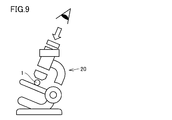
- the step (S30) of inspecting the molded body may be performed by visually inspecting the molded body irradiated with light using a magnifying glass such as the stereomicroscope 20.
- the step (S30) of inspecting the molded body may be performed by capturing a change in reflectance or absorptance from reflected light generated when the molded body is irradiated with laser light.
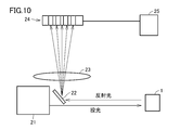
- the inspection system at this time includes, for example, a light source 21, a reflecting mirror 22, a lens 23, a light receiving element 24, and a processing device 25.
- the light source 21 is provided so as to be able to irradiate the molded body with laser light.
- the reflecting mirror 22 causes the reflected light generated when the molded body is irradiated with laser light to enter the lens 23, and the lens 23 collects the reflected light on the light receiving element 24.
- the light receiving element 24 receives the reflected light and outputs a received light signal to the processing device 25.
- the processing device 25 processes the light reception signal received from the light receiving element 24 and outputs a processing result such as the presence or absence of an internal defect in the molded body.
- the molded body (silicon nitride roller) obtained by the slidable contact step (S20) has reduced irregularities such as scratches and polishing marks on the surface including the crowning 4, irradiation to such a molded body is performed.
- the reflected light is suppressed from being reflected, absorbed, refracted due to the unevenness on the surface of the molded body. Therefore, among the light irradiated to such a molded body, light (reflected light, transmitted light, refracted light, etc.) transmitted through at least a part of the molded body also travels from the inside of the molded body to the outside. Less susceptible to irregularities on the surface of the molded body.
- the silicon nitride roller obtained by the silicon nitride roller manufacturing method according to the third embodiment has the crowning 4 formed as compared to the silicon nitride roller obtained by the conventional silicon nitride roller manufacturing method. In both the region and the region where the crowning 4 is not formed, the presence or absence of an internal defect is inspected with high accuracy from the surface to a deeper position.
- the depth from the rolling surface of the region where the shear stress is maximum in the molded body is about 120 ⁇ m.
- the method for manufacturing a silicon nitride roller it is possible to manufacture a silicon nitride roller that has been inspected with high accuracy for internal defects in a region at such a depth.
- the method for manufacturing a semiconductor element according to the third embodiment may further include a step (S30) of inspecting the molded body in the method for manufacturing a semiconductor element according to the second embodiment. That is, the semiconductor element manufacturing method according to the third embodiment further includes a step (S11) of forming the cut crowning 6 prior to the sliding contact step (S20), and the step (S30) is formed by the crowning 8. It may be a step of inspecting the formed body (corresponding to the silicon nitride roller 7). In this way, the molded body corresponding to the silicon nitride roller 7 can be inspected with high accuracy for the presence of internal defects.
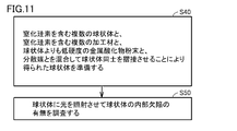
- the silicon nitride roller inspection method according to the fourth embodiment includes a plurality of cylindrical bodies 1 whose main constituent material is silicon nitride, a plurality of workpieces 2 whose main constituent material is silicon nitride, and silicon nitride.
- a molded body is prepared (step (S10)).
- the molded body includes a plurality of cylindrical bodies 1 whose main constituent material is silicon nitride, a plurality of workpieces 2 whose main constituent material is silicon nitride, a metal oxide powder having a hardness lower than that of silicon nitride, It is obtained by bringing the cylindrical body 1 and the workpiece 2 into sliding contact with each other by mixing the dispersion medium 3.
- the process of forming the cut crown 6 similar to the method for manufacturing the silicon nitride roller according to the second embodiment is performed to form the cut crown 6. May be.
- a molded body on which the crownings 4 and 8 are formed is prepared.
- the surface roughness Ra value of the molded body at this time is, for example, less than 0.004 ⁇ m on any of the surfaces, outer diameter surfaces, and end surfaces of the crownings 4 and 8.
- the molded body may be covered with a thin film whose surface is made of a light-transmitting material. In this case, irregularities such as scratches and polishing marks on the surface of a molded body whose main constituent material is silicon nitride and a thin film formed so as to cover the molded body are sufficiently reduced.
- the molded body is irradiated with light, and the presence of internal defects in the molded body is inspected by detecting light transmitted through at least a part of the molded body (step (S50)).
- This step (S50) can be performed in the same manner as the step (S30) of inspecting the molded body in the method for manufacturing the silicon nitride roller according to the third embodiment. Specifically, as shown in FIG. 9, this step (S50) can be carried out, for example, by visually inspecting the molded body irradiated with light using a magnifying glass such as a stereomicroscope. Further, in this step (S50), as shown in FIG. 10, in the step (S30) of inspecting the molded body, a change in reflectance or absorptance is detected from reflected light generated when the molded body is irradiated with laser light. It may be implemented by capturing.
- the molded body prepared in the previous step (S40) has reduced surface irregularities such as scratches and polishing marks. Therefore, it is suppressed that the light irradiated with respect to such a molded object is reflected, absorbed, refracted due to unevenness on the surface of the molded object.
- the molded body has translucency because the main constituent material is silicon nitride. Therefore, light (reflected light, transmitted light, refracted light, etc.) transmitted through at least a part of the molded body due to the translucency of silicon nitride among the light irradiated on the molded body is reflected on the surface of the molded body. Scattering or the like due to the unevenness is suppressed.
- the inspection method of the present silicon nitride roller the presence or absence of internal defects in a deeper region with respect to the entire surface of the silicon nitride roller including crowning is inspected with higher accuracy than the conventional inspection method of the silicon nitride roller. can do.
- the inspection system shown in FIGS. is not. As long as it is possible to detect light transmitted through at least part of the molded body by irradiating the molded body with light, any method can be adopted.
- the dimensions and surface roughness of the crowning portion were measured.
- Example 1 to Sample 3 Example 1
- the cylindrical body contains 80% by volume or more and 98% by volume or less of silicon nitride, and is polished by using diamond as abrasive grains. Both the outer diameter ⁇ and the length L of the cylindrical body were 13 mm.
- the prepared cylindrical body had a surface roughness (arithmetic average roughness) Ra value on the outer diameter surface of 0.0514 ⁇ m and a surface roughness Ra value on the end surface of 0.0475 ⁇ m.
- the processed material 2 was a spherical body containing 80% by volume to 98% by volume of silicon nitride.
- the outer diameter of the processed material 2 was 7 mm or more and 12 mm or less.
- the prepared cylindrical body 1 is accommodated in a ball mill (container 10), and is rotated so that the cylindrical body 1, the work material 2, the dispersion medium 3, and the metal
- the oxide powder was mixed.
- Chromium oxide (CrO 2 ), and cerium oxide (CeO 2 ) were housed in a ball mill container 10 and subjected to ball milling.
- the ball mill container 10 was made of polyethylene as the container material.
- the shape of the ball mill container 10 was cylindrical, and the dimensions of the container were an inner diameter ⁇ 200 mm and an axial length L200 m.
- the metal oxide powder was ball milled using iron oxide to obtain a silicon nitride roller 5 of Sample 1. Further, ball milling was performed using chromium oxide to obtain a silicon nitride roller 5 of Sample 2. Ball milling was performed using cerium oxide to obtain a silicon nitride roller 5 of Sample 3.
- Example 4 Sample 5: Comparative Example 1
- a plurality of the cylindrical bodies, a plurality of the processing materials, water as a dispersion medium, and the conditions shown in Tables 1 and 2 as in Samples 1 to 3 of Example 1 Aluminum oxide (Al 2 O 3 ) having a hardness higher than that of silicon nitride was accommodated in the ball mill container, and ball mill treatment was performed under the conditions shown in Table 2 to obtain a silicon nitride roller of Sample 4.
- the silicon nitride roller of sample 4 was produced by changing only the metal oxide powder with respect to the silicon nitride rollers of sample 1 to sample 3.
- a plurality of the cylindrical bodies, a plurality of the processed materials, and water as a dispersion medium are accommodated in the ball mill container and shown in Table 1 without using metal oxide powder (metal Ball milling was performed under the conditions (only the amount of oxide powder contained was changed to 0 g) and the conditions shown in Table 2, and a silicon nitride roller of Sample 5 was obtained.
- Example 6 to Sample 10 Comparative Example 2
- ball milling was performed in the same manner as in Example 1 and Comparative Example 2 using a processed material whose main constituent material was aluminum oxide to obtain silicon nitride rollers of Sample 6 to Sample 10.
- the silicon nitride rollers of Sample 6 to Sample 10 are manufactured under the same conditions as the silicon nitride rollers of Sample 1 to Sample 5, except for the processed material.
- the columnar body contained 80% by volume to 98% by volume of silicon nitride, and was polished using diamond as abrasive grains.
- the processed material 2 was a spherical body containing 80% by volume to 98% by volume of aluminum oxide.
- the outer diameter of the processed material 2 was 7 mm or more and 12 mm or less.
- Table 4 shows the measurement results of the cylindrical body before the ball mill treatment described above with respect to the silicon nitride rollers of Sample 6 to Sample 10 subjected to the ball mill treatment using a processing material whose main constituent material is aluminum oxide. It shows together with a result.
- the crowning length and crowning drop amount were calculated from the cross-sectional profiles obtained by obtaining the cross-sectional profiles of the silicon nitride rollers of Sample 1 to Sample 10 using a shape measuring instrument (using Mitutoyo Form Tracer).
- FIG. 12 shows cross-sectional profile data of Sample 3. The vertical axis in FIG.
- the ratio of the crowning length L2 to the bus length L3 was 9.2%, 13.8%, and 11.5%, respectively. That is, the ratio of the crowning length L2 to the bus length L3 in the silicon nitride rollers of Samples 1 to 3 was 9% or more and 25% or less. In other words, the silicon nitride rollers of Samples 1 to 3 were sufficiently crowned to avoid edge loading as rollers.
- the surface roughness (Ra) of the outer diameter surface and the end surface of the silicon nitride rollers of Sample 1 to Sample 3 are the same as the surface roughness (Ra) of the outer diameter surface and the end surface of the cylindrical body before the ball mill treatment. Compared with this, it was greatly reduced, and the surface roughness (Ra) sufficient for the roller was improved. On the other hand, there was no significant change in shape accuracy such as roundness before and after ball milling.
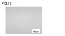
- FIG. 13 shows a microscopic image of the surface of the boundary between the crowning and the outer diameter surface in the silicon nitride roller of Sample 2.
- FIG. 14 shows a microscopic image of the outer diameter surface of the silicon nitride roller of Sample 2.
- FIG. 15 the microscope image of the end surface of the silicon nitride roller of the sample 2 is shown.
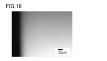
- FIG. 16 shows a microscopic image of the crowning surface of the silicon nitride roller of Sample 2.
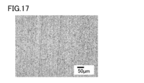
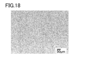
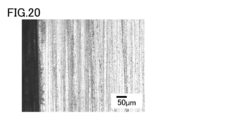
- FIG. 17 to FIG. 20 illustrate the crowning of a silicon nitride roller that has been subjected to a crowning process using a diamond grindstone (specifically, a superfinish process using a diamond grindstone with a # 2000 grindstone).
- the microscopic images of the surface of the boundary portion between the outer diameter surface and the outer diameter surface, the outer diameter surface, the end surface, and the crowning surface are shown.
- the silicon nitride roller of sample 2 has scratches on the surface of the boundary between the crowning and the outer diameter surface, the outer diameter surface, the end surface, and the crowning surface. It was confirmed that polishing marks were not noticeable.
- the silicon nitride rollers of Sample 4 and Sample 5 have a crowning drop amount of less than 1 ⁇ m, and the ratio of the crowning length L2 to the bus bar length L3 is less than 1.0%. In order to avoid this, sufficient crowning was not formed. In particular, in the silicon nitride roller of Sample 5, no crowning was formed. The ratio of the crowning length L2 to the bus bar length L3 of the silicon nitride roller of sample 4 was 0.8%, which was lower than that of the silicon nitride rollers of sample 1 to sample 3.
- the surface roughness (Ra) of the outer diameter surface and the end surface of the silicon nitride roller of Sample 5 was slightly smaller than that before the ball mill treatment, but since it is 0.04 ⁇ m or more, the reduction in bearing life is suppressed. There was not enough improvement from the viewpoint.
- the surface roughness Ra value of the outer diameter surface was increased from 0.0514 ⁇ m before the ball mill treatment to 0.0522 ⁇ m, and the surface roughness Ra value of the end surface was 0. 0 before the ball mill treatment. It increased from 0475 ⁇ m to 0.0523 ⁇ m. This is because when the cylindrical body made of silicon nitride and the workpiece are slidably contacted, the surface of the cylindrical body is rubbed with high-hardness aluminum oxide, so that scratches and polishing marks are generated on the surface. Conceivable.
- the metal oxide powder having a hardness lower than that of the cylindrical body whose main constituent material is silicon nitride, and the main constituent material similar to the cylindrical body is silicon nitride.
- a silicon nitride roller in which crowning is formed at both ends in the axial direction and irregularities such as scratches and polishing marks on the surface are sufficiently reduced.
- a cylindrical body with a sufficiently high shape accuracy, such as roundness is ball milled to achieve high shape accuracy and a crowning to sufficiently reduce scratches and polishing marks on the surface. It was confirmed that the obtained silicon nitride roller can be obtained.
- the silicon nitride rollers of Samples 6 to 10 have a crowning drop amount of less than 1 ⁇ m, and the ratio of the crowning length L2 to the bus bar length L3 of the silicon nitride roller is 1 respectively. 0.5%, 1.5%, 1.5%, and 0.7%. That is, the silicon nitride rollers of Samples 6 to 9 were not sufficiently crowned to avoid edge loading as rollers. No crowning was formed on the silicon nitride roller of Sample 10.
- the surface roughness (Ra) of the outer diameter surface and the end surface of the silicon nitride rollers of Sample 6 to Sample 8 are the same as the surface roughness (Ra) of the outer diameter surface and the end surface of the cylindrical body before the ball mill treatment. Although it is slightly smaller than the above, since it is 0.03 ⁇ m or more, sufficient improvement was not seen from the viewpoint of suppressing reduction in bearing life. Further, the surface roughness of the silicon nitride rollers of Sample 9 and Sample 10 was equal to or larger than that before the ball mill treatment, and sufficient improvement was not seen from the viewpoint of suppressing reduction in bearing life.
- Example 1 Comparative Example 2
- the type of metal oxide powder was changed. Regardless, it was confirmed that sufficient crowning was not formed and irregularities such as scratches and polishing marks on the surface could not be reduced sufficiently.
- the dimensions and surface roughness of the crowning portion were measured.
- Example 11 Example 2
- the cylindrical body contains 80% by volume or more and 98% by volume or less of silicon nitride, and is polished by using diamond as abrasive grains. Both the outer diameter ⁇ and the length L of the cylindrical body were 13 mm.
- the prepared cylindrical body had a surface roughness (arithmetic average roughness) Ra value on the outer diameter surface of 0.0514 ⁇ m and a surface roughness Ra value on the end surface of 0.0475 ⁇ m.
- the processed material 2 was a spherical body containing 80% by volume to 98% by volume of silicon nitride.
- the outer diameter of the processed material 2 was 7 mm or more and 12 mm or less.
- cut crowning 6 was formed at both ends of the prepared cylindrical body 1 in the axial direction.
- the cut crowning 6 was formed by grinding the cylindrical body 1 using a diamond grindstone having a ground surface shape provided in the cut crowning shape, and transferring the grinding surface shape to the cylindrical body 1.
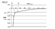
- FIG. 21 the cross-sectional profile in the cut crowning 6 of the cylindrical body 1 is shown.
- the cross-sectional profile was acquired using a shape measuring instrument (using Mitutoyo Form Tracer).
- the cylindrical body 1 on which the cut crowning 6 is formed is accommodated in a ball mill (container 10), and the cylindrical body 1, the work material 2, and the dispersion medium 3 are rotated by rotating the cylindrical body 1.
- Metal oxide powder was mixed. Specifically, under the conditions shown in Tables 1 and 5, a plurality of cylindrical bodies 1, a plurality of processed materials 2, water as a dispersion medium 3, and iron oxide (Fe 2 O 3 ) as a metal oxide powder was stored in a ball mill container 10 and subjected to a ball mill treatment.
- the ball mill container 10 was the same as the ball mill container 10 used in Example 1.
- a silicon nitride roller 7 of Sample 11 was obtained.
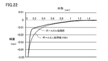
- FIG. 22 shows the cross-sectional profile of the silicon nitride roller 7 in the crowning 8 and the cross-sectional profile of the cut crowning 6 of the cylindrical body 1 before the ball mill treatment shown in FIG.
- the silicon nitride roller of Sample 11 has a crowning drop amount of 24 ⁇ m, and the ratio of the crowning length L2 to the length L3 of the bus bar of the silicon nitride roller is 10.8%. As a result, sufficient crowning was formed to avoid edge loading. Further, the ratio of the crowning length L2 to the bus bar length L3 of the silicon nitride roller of sample 11 was larger than the ratio L2 / L3 of the silicon nitride rollers of sample 1 to sample 3 in Example 1.
- the silicon nitride roller of sample 11 has a crowning shape that approximates a logarithmic curve as compared with the silicon nitride roller of sample 1 in Example 1, and a crowning having a more ideal shape is formed. It was. Further, the surface roughness (Ra) of the outer diameter surface and the end surface of the silicon nitride roller of the sample 11 is larger than the surface roughness (Ra) of the outer diameter surface and the end surface of the cylindrical body before the ball mill treatment. The surface roughness (Ra) was reduced to a sufficient level as a roller. On the other hand, there was no significant change in shape accuracy such as roundness before and after ball milling.
- FIG. 23 shows a cross-sectional profile of the molded body of the sample 12.
- the molded body of the sample 12 is rounded at the boundary between the outer diameter surface and the end surface, but the crowning like the molded body of the sample 11 is not formed. That is, the silicon nitride roller manufacturing method according to the first embodiment can easily form the crowning that has been difficult to form by the barrel polishing method conventionally employed as the crowning processing method.
- an appearance inspection was performed on the silicon nitride roller.
- the plurality of columnar bodies contained 80% by volume or more and 98% by volume or less of silicon nitride, and were polished using diamond as abrasive grains.
- the surface roughness (arithmetic mean roughness) Ra value of the cylindrical body was 0.01 ⁇ m.
- metal inclusion defects stainless steel (SUS) powder having a maximum outer width of 45 ⁇ m were introduced at positions where the depth from the polished surface (surface) was 50 ⁇ m, 80 ⁇ m, 120 ⁇ m, and 150 ⁇ m, respectively, and samples 13 to Four types of columnar bodies of sample 16 were prepared, and the position where the metal inclusion defect was introduced in each columnar body was at the above depth from the polished surface using an X-ray CT (Computed Tomography) apparatus. confirmed.
- SUS stainless steel
- Whether or not the internal defect could be detected by the following inspection method was evaluated for the cylindrical bodies of Sample 13 to Sample 16.
- a first inspection method as shown in FIG. 9, a method of visually inspecting the cylindrical bodies of Sample 13 to Sample 16 using a stereomicroscope 20 as a magnifier was adopted.
- a second inspection method a method is used in which the change in the absorptance is detected from the reflected light generated when the cylindrical bodies of Sample 13 to Sample 16 are irradiated with the laser beam using the inspection system shown in FIG. did.
- the ball mill treatment includes a plurality of cylindrical bodies whose main constituent material is silicon nitride, including a cylindrical body of Sample 13 to Sample 16, a plurality of workpieces whose main constituent material is silicon nitride, and dispersion. Water as a medium and iron oxide as a metal oxide powder were accommodated in a ball mill container, and the conditions shown in Table 1 and Table 2 were used.
- the processed material was a spherical body containing 80% by volume to 98% by volume of silicon nitride.
- the outer diameter of the processed material 2 was 7 mm or more and 12 mm or less.
- the first and second inspection methods are used even before ball milling.
- the metal inclusion defect could be detected.
- both the first and second inspection methods detect the metal inclusion defect for the cylindrical body of the sample 15 and the sample 16 before the ball mill treatment. I could't.
- the metal inclusion defects could be detected by the first and second inspection methods for the molded bodies of the sample 15 and the sample 16 after the ball mill treatment.
- the cylindrical body before the ball mill treatment has irregularities such as scratches and polishing marks on the surface, and the internal defects exist at a deep position from the surface because the transmitted light is scattered and attenuated on the surface.
- the surface of the molded body (silicon nitride roller) was measured by the method for manufacturing the silicon nitride roller according to the third embodiment and the method for inspecting the silicon nitride roller according to the fourth embodiment. It was confirmed that the presence or absence of internal defects could be inspected from a deeper position to a deeper position. Further, it was confirmed that the silicon nitride roller inspection method according to the fourth embodiment is particularly suitable as a silicon nitride roller inspection method for bearing rolling elements.
- the depth from the rolling surface is at least about 150 ⁇ m.
- an internal defect of a predetermined size (for example, the maximum outer width is 25 ⁇ m or more) can be evaluated. It is possible to select silicon nitride rollers (or compacts) having no defects.
- the present invention is particularly advantageously applied to a silicon nitride roller used for a rolling element for a bearing and a method for manufacturing a silicon nitride roller.
Landscapes
- Engineering & Computer Science (AREA)
- Chemical & Material Sciences (AREA)
- Ceramic Engineering (AREA)
- General Engineering & Computer Science (AREA)
- Mechanical Engineering (AREA)
- Manufacturing & Machinery (AREA)
- Materials Engineering (AREA)
- Structural Engineering (AREA)
- Organic Chemistry (AREA)
- Rolling Contact Bearings (AREA)
Abstract
クラウニングが形成されており、かつ従来よりも高効率で製造可能な窒化珪素ころおよびクラウニングが形成されている窒化珪素ころを従来よりも高効率で製造可能な窒化珪素ころの製造方法を提供する。主な構成材料が窒化珪素である複数の円柱状体(1)と、主な構成材料が窒化珪素である複数の加工材(2)と、円柱状体(1)よりも低硬度の金属酸化物粉末と、分散媒(3)とを準備する工程と、複数の円柱状体(1)と複数の加工材(2)と金属酸化物粉末と分散媒(3)とを混合することにより円柱状体(1)と加工材(2)とを摺接させる工程とを備える。
Description
本発明は、窒化珪素ころ、窒化珪素ころの製造方法、および窒化珪素ころの検査方法に関し、特に軸受用転動体に好適である窒化珪素ころ、窒化珪素ころの製造方法、および窒化珪素ころの検査方法に関する。
ベアリング(軸受)用転動体の材料には主に軸受鋼が用いられるが、高速回転、絶縁性、耐熱性、耐腐食性などの特性が要求される用途にはセラミックスが用いられる。一般にベアリング用のセラミックス材料には、高強度、高靱性および高硬度を有するとともに耐熱性および耐食性に優れる窒化珪素(Si3N4)が用いられる。
転動体がころである場合には、ころにおいて軌道面と接触する外径面の端部に過大な圧力(エッジロード)が発生することがある。エッジロードが生じた場合、ころの寿命が低下するといった問題が生じる。エッジロードを避けるため,一般にころの上記端部にはクラウニングが形成されている。
ころにクラウニングを形成する方法としては、一般にダイヤモンド砥石を用いてワークを研削することにより、該砥石の形状が転写されたころを形成する方法が採用されている。
また、ころにクラウニングを形成する方法としては、曲率を持ったクラウニング型ねじ付き調整車を使い、砥石に対して意図的に円錐ころの姿勢を変化させながら円錐ころ外径にクラウニングが転写されるように研削を行う方法が知られている(特開2010-284775号公報(特許文献1)参照)。
また、転動体がころである場合であって、ころの摩擦係数を十分に低下させる必要がある場合には、ころの少なくとも外径面を鏡面化する鏡面加工が実施されている。
しかしながら、上述した従来のクラウニング加工方法では、被加工物である窒化珪素が高硬度であるために加工能率が低い。
本発明は、上記のような課題を解決するためになされたものである。本発明の主たる目的は、クラウニングが形成されており、かつ従来よりも高効率で製造可能な窒化珪素ころおよびクラウニングが形成されている窒化珪素ころを従来よりも高効率で製造可能な窒化珪素ころの製造方法を提供することにある。
本発明の窒化珪素ころの製造方法は、主な構成材料が窒化珪素である複数の円柱状体と、主な構成材料が窒化珪素である複数の加工材と、前記円柱状体よりも低硬度の金属酸化物粉末と、分散媒とを準備する工程と、複数の前記円柱状体と複数の前記加工材と前記金属酸化物粉末と前記分散媒とを混合することにより前記円柱状体と前記加工材とを摺接させる工程とを備える。
本発明に依れば、クラウニングが形成されており、かつ従来よりも高効率で製造可能な窒化珪素ころおよびクラウニングが形成されている窒化珪素ころを従来よりも高効率で製造可能な窒化珪素ころの製造方法を提供することができる。
以下、図面を参照して、本発明の実施の形態について説明する。なお、以下の図面において同一または相当する部分には同一の参照番号を付しその説明は繰返さない。
はじめに、本発明の実施の形態の概要を列挙する。
(1) ある実施例において、窒化珪素ころ5,7は、主な構成材料が窒化珪素であるころであって、転動面を含み軸を囲むように形成されている外径面を有し、外径面の上記軸の延在方向における両端部にはそれぞれクラウニング4,8が形成されており、ころの表面からの深さが150μmよりも浅い領域において、外形の最大幅が25μm以上の欠陥が無い。
(1) ある実施例において、窒化珪素ころ5,7は、主な構成材料が窒化珪素であるころであって、転動面を含み軸を囲むように形成されている外径面を有し、外径面の上記軸の延在方向における両端部にはそれぞれクラウニング4,8が形成されており、ころの表面からの深さが150μmよりも浅い領域において、外形の最大幅が25μm以上の欠陥が無い。
このような窒化珪素ころ5,7が軸受用転動体として用いられた場合、転動面からの深さが150μmよりも浅い領域に、軸受使用時の窒化珪素ころ5,7において最大のせん断応力が作用する領域は含まれている。そのため、窒化珪素ころ5,7は、このような最大のせん断応力が印加されたときにも、内部欠陥を起点としたクラック等の発生が抑制されている。つまり、表面からの深さが150μmよりも浅い領域において、外形の最大幅が25μm以上の欠陥が無い窒化珪素ころ5,7は、軸受用転動体に好適である。
なお、このような窒化珪素ころ5,7は、表面の傷や研磨痕などの凹凸が十分に低減されているため、上述した成形体を検査する工程(S30)を備える窒化珪素ころの製造方法、または窒化珪素ころの検査方法が実施されることにより得られる(選別され得る)。
(2)別の実施例において、窒化珪素ころ5,7は、主な構成材料が窒化珪素である窒化珪素ころであって、転動面を含み、軸を囲むように形成されている外径面5A,7Aを有し、外径面の軸の延在方向における両端部にはそれぞれクラウニング4,8が形成されている。クラウニング4,8は、主な構成材料が窒化珪素である複数の円柱状体1と、主な構成材料が窒化珪素である複数の加工材2と、円柱状体1よりも低硬度の金属酸化物粉末と、分散媒3とを混合して円柱状体1と加工材2とを摺接させることにより形成されている。窒化珪素ころ5,7の軸を含む窒化珪素ころ5,7の断面上において、外径面(以下、当該断面上の外径面を母線という)の上記軸の延在方向における長さL3(図3参照)に対するクラウニング4,8の上記軸の延在方向における長さL2(以下、クラウニング長さという、図3参照)の比率は、それぞれ9%以上25%以下である。
つまり、クラウニング長さL2は、上記軸の延在方向における片端部に形成されている1のクラウニング4,8の上記軸の延在方向における長さである。言い換えると、クラウニング長さL2は、平面として形成されている外周面5A,7Aの端部a(曲面として形成されているクラウニング4と接続される部分)と端面5B,7Bとの上記軸の延在方向における距離である。母線の上記軸の延在方向における長さL3は、上記軸の延在方向の両端部に形成されたクラウニング4,8間に挟まれるように形成されている外径面5A,7Aの上記軸の延在方向における長さである。つまり、母線の上記軸の延在方向における長さL3に対するクラウニング長さL2の比率は、L2/L3で表される。
本実施例における窒化珪素ころ5,7は、このようにクラウニング長L2が長く形成されているため、エッジロードに起因したころ寿命の低下を効果的に抑制することができる。従来の窒化珪素ころの製造方法ではこのように長いクラウニング長L2を形成することが困難であった。しかし、本実施例における窒化珪素ころ5,7のクラウニング4,8は、複数の円柱状体1と、複数の加工材2と、円柱状体1よりも低硬度の金属酸化物粉末と、分散媒3とを混合して円柱状体1と加工材2とを摺接させることにより(後述する各実施例における窒化珪素ころの製造方法により)形成されている。そのため、本実施例の窒化珪素ころ5,7は、従来の窒化珪素ころの製造方法により製造された窒化珪素ころと比べて容易に製造され得る。
(3)別の実施例において、窒化珪素ころの製造方法は、主な構成材料が窒化珪素(Si3N4)である複数の円柱状体1と、主な構成材料が窒化珪素(Si3N4)である複数の加工材2と、円柱状体1よりも低硬度の金属酸化物粉末と、分散媒3とを準備する工程(S10)と、複数の円柱状体1と複数の加工材2と金属酸化物粉末と分散媒3とを混合することにより円柱状体1と加工材2とを摺接させる工程(S20)とを備える。
ここで、円柱状体1の主な構成材料が窒化珪素であるとは、円柱状体1の50体積%以上を構成する材料が窒化珪素であるものをいう。言い換えると、円柱状体1は、50体積%以上の窒化珪素を含んでおり、たとえば80体積%以上98体積%以下の窒化珪素を含んでいる。また、円柱状体1と加工材2とを摺接させるとは、円柱状体1と加工材2とが互いの表面を摺りあいながら接触している状態に置くことをいう。なお、摺接させる工程(S20)では、円柱状体1と加工材2とが摺接されるだけでなく円柱状体1同士も摺接され得る。
このようにすれば、図1を参照して、摺接させる工程(S20)において、円柱状体1は、同じく主な構成材料が窒化珪素である加工材2若しくは他の円柱状体1と摺接される際にその表面が金属酸化物粉末に擦過される。このとき、金属酸化物粉末の種類によっては、円柱状体1はその表面において金属酸化物粉末と化学的な反応を起こす。このような機械的作用および化学的作用により、円柱状体1をクラウニング加工することができ、クラウニング4,8が形成された窒化珪素ころ5,7を得ることができる。さらにこれと同時に、当該機械的作用および化学的作用により、円柱状体1の表面(外周面1A、端面1B)に生じていた凹凸部を緩和あるいは除去することができる。さらに、外周面1A、端面1Bおよび本工程においてクラウニング4,8が形成され始めた場合には該クラウニング面4A,8Aの表面粗さを低減することができる。つまり、機械的作用および化学的作用により、円柱状体1の全表面に対し同時に加工を行うことができる。
さらに、摺接させる工程(S20)において、円柱状体1は自身より高硬度の材料からなる砥粒で研磨されることがないため、その表面(外周面1A、端面1Bおよびクラウニング面4A,8A)に傷や研磨痕が生じることを抑制することができる。
このように、本実施例に係る窒化珪素ころの製造方法によれば、準備する工程(S10)においてクラウニング4,8が形成されておらず、外周面1Aや端面1Bに傷や研磨痕などの凹凸部が形成されている円柱状体1が準備されても、当該円柱状体1に対して摺接させる工程(S20)を実行することにより、クラウニング4,8が形成され、かつその外径面5A,7Aおよび端面5B,7Bにおいて上記凹凸部が緩和、除去された窒化珪素ころ5,7を得ることができる。また、該窒化珪素ころ5,7は、その外径面5A,7A、端面5B,7Bおよびクラウニング面4A,8Aの表面粗さが小さい。そのため、窒化珪素ころ5,7は、エッジロードや表面の凹凸に起因したころの寿命低下が抑制されている。
(4)別の実施例において、金属酸化物粉末は、酸化鉄(Fe2O3)、酸化クロム(CrO2)、および酸化セリウム(CeO2)からなる群から選択される少なくとも1つである。
金属酸化物粉末の役割は現状明らかではないが、本願発明者は以下のように推測している。Fe2O3、CrO2、およびCeO2は、窒化珪素に対してその表面を酸化させる触媒として機能すると考えられる。主な構成材料が窒化珪素である円柱状体1と金属酸化物粉末とを混合することにより、円柱状体1の表面を酸化させてSiO2層を形成することができると考えられる。特に、円柱状体1の表面において凸状に形成されている外周面1Aと端面1Bとの境界部や傷や研磨痕などの凹凸部などの凸部分では、金属酸化物に擦過される確率が高いためSiO2層が形成され易いと考えられる。さらに、当該凸部分では加工材2や他の円柱状体1と摺接される確率が高いため、SiO2層が除去され易いと考えられる。その結果、摺接させる工程(S20)により、円柱状体1に対してクラウニング加工を行うことができるとともに、円柱状体1の表面上に形成された傷や研磨痕などの凹凸部を緩和、除去することができると考えられる。
さらに、Fe2O3、CrO2、およびCeO2はそれぞれ窒化珪素(Si3N4)よりも低硬度であり、上記摺接させる工程(S20)において混合される円柱状体1と加工材2と金属酸化物粉末と分散媒3とにおいて、窒化珪素を主な構成材料とする円柱状体1よりも硬度が高い材料が存在しない。そのため、該工程(S20)中において円柱状体1の表面に上記凹凸部が新たに形成されることは抑制されていることから、より効果的に当該凹凸部を緩和、除去することができる。
つまり、本実施例の窒化珪素ころの製造方法によれば、金属酸化物粉末をFe2O3、CrO2、およびCeO2からなる群から選択される少なくとも1つとすることにより、クラウニング4,8が形成され、かつ表面上の傷や研磨痕などの凹凸が低減されている窒化珪素ころ5,7をより容易に製造することができる。
(5)別の実施例において、摺接させる工程(S20)は、円柱状体1と、加工材2と、金属酸化物粉末と、分散媒3とを容器10に収容する工程(S21)と、容器10を動かすことにより円柱状体1と加工材2と金属酸化物粉末と分散媒3とを混合する工程(S22)とを含む。
このようにすれば、容器を動かすことなく撹拌子などにより円柱状体と金属酸化物粉末と分散媒とを混合して得られた窒化珪素ころと比べて、窒化珪素ころの表面の傷や研磨痕などの凹凸および表面粗さRa値を低減することができる。
また、混合する工程(S22)において、容器10は、その内部に収容されている複数の円柱状体1と加工材2と金属酸化物粉末と分散媒3とを混合しながら円柱状体1と加工材2とを摺接させることができる限りにおいて、任意に動かされ得るが、たとえば回転される。
(6)別の実施例において、容器10は筒状体であり、混合する工程(S22)では、容器10を回転させることにより円柱状体1と加工材2とを摺接させる。
これにより、容器10内に主要されている円柱状体1、加工材2、金属酸化物粉末および分散媒3を均一に混合することができるとともに、円柱状体1と加工材2とを摺接させることができる。
(7)別の実施例において、加工材2は球状体である。このようにすれば、円柱状体1に対する加工バラつきを低減することができる。
(8)別の実施例では、摺接させる工程(S20)において、金属酸化物粉末は、分散媒3の1L当たり60g以上80g以下の割合で円柱状体1と分散媒3と混合される。
このようにすれば、高能率かつ低コストで、クラウニング形状が形成されているとともに表面上の傷や研磨痕などの凹凸が低減されている窒化珪素ころを製造することができる。
(9)別の実施例に係る窒化珪素ころの製造方法は、主な構成材料が窒化珪素である複数の円柱状体1と、主な構成材料が窒化珪素である複数の加工材2と、円柱状体1よりも低硬度の金属酸化物粉末と、分散媒3とを準備する工程(S10)と、複数の円柱状体1と複数の加工材2と金属酸化物粉末と分散媒3とを混合することにより円柱状体1と加工材2とを摺接させる工程(S20)と、摺接させる工程(S20)により円柱状体1から得られた成形体(窒化珪素ころ5,7)を検査する工程(S30)とを備える。上記成形体を検査する工程(S30)では、成形体に対して光を照射させ、成形体の少なくとも一部を透過した光を検出することにより、成形体の内部欠陥の有無を検査する。
ここで、円柱状体1の主な構成材料が窒化珪素であるとは、円柱状体1の50体積%以上を構成する材料が窒化珪素であるものをいう。言い換えると、円柱状体1は、50体積%以上の窒化珪素を含んでおり、たとえば80体積%以上98体積%以下の窒化珪素を含んでいる。また、円柱状体1と加工材2とを摺接させるとは、円柱状体1と加工材2とが互いの表面を摺りあいながら接触している状態に置くことをいう。なお、摺接させる工程(S20)では、円柱状体1と加工材2とが摺接されるだけでなく円柱状体1同士も摺接され得る。
このようにすれば、図1を参照して、摺接させる工程(S20)において、円柱状体1は、同じく主な構成材料が窒化珪素である加工材2若しくは他の円柱状体1と摺接される際にその表面が金属酸化物粉末に擦過される。このとき、金属酸化物粉末の種類によっては、円柱状体1はその表面において金属酸化物粉末と化学的な反応を起こす。このような機械的作用および化学的作用により、円柱状体1をクラウニング加工することができ、クラウニング4,8が形成された成形体を得ることができる。さらにこれと同時に、当該機械的作用および化学的作用により、円柱状体1の表面(外周面1A、端面1B)に生じていた凹凸部の程度を緩和したりあるいは凹凸部を除去したりすることができる。さらに、外周面1A、端面1Bおよび本工程においてクラウニング4,8が形成され始めた場合には該クラウニング面4A,8Aの表面粗さを低減することができる。つまり、機械的作用および化学的作用により、円柱状体1の全表面に対し同時に加工を行うことができる。
検査する工程(S30)において成形体に照射された光は、窒化珪素の透光性により成形体の内部を透過して、成形体の内部欠陥等により反射、吸収、屈折などされる。ここで、成形体の表面上に傷や研磨痕などの凹凸が形成されている場合には、成形体の内部を透過して再び成形体の表面に達した光は当該表面上の凹凸により散乱あるいは減衰される。よって、従来の窒化珪素ころの製造方法により製造された窒化珪素ころは、表面粗さが大きく、窒化珪素の透光性を利用した内部欠陥評価が可能な領域は表面近傍の領域に限られていた。
これに対し、上述のように、摺接させる工程(S20)により得られた成形体は、表面上の傷や研磨痕などの凹凸が低減されているため、このような成形体に対して照射された光は成形体の表面上の凹凸に起因して反射、吸収、屈折などされることが抑制されている。そのため、このような成形体に照射された光のうち、成形体の少なくとも一部を透過した光(反射光、透過光、屈折光など)は、成形体の内部から外部に進行する際にも成形体の表面上の凹凸の影響を受にくい。その結果、従来よりも成形体内部のより深い位置からの反射光などを検出することができる。このため、このような成形体の少なくとも一部を透過した光(反射光、透過光、屈折光など)を捉えることにより、成形体の表面からより深い領域での内部欠陥の有無などの情報を精度良く得ることができる。
つまり、本実施の形態に係る窒化珪素ころの製造方法によれば、従来の窒化珪素ころの製造方法と比べて、より深い領域の内部欠陥についても高い精度で検査がなされた窒化珪素ころ5,7を製造することができる。たとえば、成形体が軸受用転動体として使用されたときに、成形体においてせん断応力が最大となる領域の転動面からの深さは約120μmであるが、従来の窒化珪素ころの製造方法ではこのような深さにある領域の内部欠陥については高い精度で検査された窒化珪素ころを製造することができなかった。これに対し、本窒化珪素ころの製造方法では、このような深さにある領域の内部欠陥についても高い精度で検査された窒化珪素ころ5,7を製造することができる。
(10) 別の実施例において、成形体を検査する工程(S30)は、光が照射された成形体を拡大鏡を用いて目視検査することにより実施されてもよい。
このようにしても、成形体の内部欠陥の有無を高精度にかつ容易に検査することができる。
(11) 別の実施例において、成形体を検査する工程(S30)は、成形体にレーザ光を照射したときに生じる反射光から、反射率または吸収率の変化を捉えることにより実施されてもよい。
このようにしても、成形体の内部欠陥の有無を高精度にかつ容易に検査することができる。
(12) 別の実施例の窒化珪素球状体の検査方法は、主な構成材料が窒化珪素である複数の円柱状体1と、主な構成材料が窒化珪素である複数の加工材2と、円柱状体1よりも低硬度の金属酸化物粉末と、分散媒3とを混合して円柱状体1と加工材2とを摺接させることにより円柱状体1から形成された成形体を準備する工程と、成形体に対して光を照射させ、成形体の少なくとも一部を透過した光を検出することにより、成形体の内部欠陥の有無を検査する工程とを備える。
このようにすれば、検査対象である成形体の表面の傷や研磨痕などの凹凸が十分に低減されているため、このような成形体に対して照射された光は成形体の表面上の凹凸に起因して反射、吸収、屈折などされることが抑制されている。そのため、このような成形体に照射された光のうち、窒化珪素の透光性により成形体の少なくとも一部を透過した光(反射光、透過光、屈折光など)は、成形体の表面上の凹凸により散乱等されることが抑制されている。その結果、従来よりも成形体内部のより深い位置からの反射光などを検出することができる。このため、このような成形体の少なくとも一部を透過した光(反射光、透過光、屈折光など)を捉えることにより、成形体の表面からより深い領域での内部欠陥の有無などの情報を精度良く得ることができる。
つまり、本窒化珪素ころの検査方法によれば、従来の窒化珪素ころの検査方法と比べて、窒化珪素ころに対してより深い領域の内部欠陥についても高い精度で検査することができる。
(実施の形態1)
図1~図4を参照して、実施の形態1に係る窒化珪素ころの製造方法について説明する。実施の形態1に係る窒化珪素ころの製造方法は、主な構成材料が窒化珪素(Si3N4)である複数の円柱状体1と、主な構成材料が窒化珪素(Si3N4)である複数の加工材2と、円柱状体1よりも低硬度の金属酸化物粉末(図示しない)と、分散媒3とを準備する工程(S10)と、複数の円柱状体1と複数の加工材2と金属酸化物粉末と分散媒3とを混合することにより円柱状体1と加工材2とを摺接させる工程(S20)とを備える。
図1~図4を参照して、実施の形態1に係る窒化珪素ころの製造方法について説明する。実施の形態1に係る窒化珪素ころの製造方法は、主な構成材料が窒化珪素(Si3N4)である複数の円柱状体1と、主な構成材料が窒化珪素(Si3N4)である複数の加工材2と、円柱状体1よりも低硬度の金属酸化物粉末(図示しない)と、分散媒3とを準備する工程(S10)と、複数の円柱状体1と複数の加工材2と金属酸化物粉末と分散媒3とを混合することにより円柱状体1と加工材2とを摺接させる工程(S20)とを備える。
まず、主な構成材料が窒化珪素である複数の円柱状体1と、主な構成材料が窒化珪素(Si3N4)である複数の加工材2と、円柱状体1よりも低硬度の金属酸化物粉末と、分散媒3とを準備する(工程(S10))。
円柱状体1は、たとえば窒化珪素の原料粉末が球状に成形され、当該成形体に対して加圧焼結や常圧焼結などが実施されることにより準備される。円柱状体1は、さらに、窒化珪素よりも高硬度の砥粒(たとえばダイヤモンド、緑色炭化珪素(GC)系、白色アルミナ(WA)系など)により研磨されたものであってもよい。円柱状体1は、50体積%以上の窒化珪素を含んでおり、たとえば80体積%以上98体積%以下の窒化珪素を含んでいる。円柱状体1を構成する材料には、たとえば焼結助剤などが含まれていてもよい。
円柱状体1は、外周面1Aと端面1Bとを有している。外周面1Aと端面1Bとは、たとえば直交している。円柱状体1の寸法(外径および長さなど)は、任意の大きさとすればよいが、たとえば軸受用転動体としてJIS規格やISO規格などにより標準化された寸法である。本工程(S10)では、円柱状体1は複数個準備される。このとき、複数の円柱状体1は、それぞれほぼ同寸法であるのが好ましい。
なお、円柱状体1は、軸を有し、軸を囲むように外周面1Aが形成されている限りにおいて、完全な円柱形状に設けられていなくてもよい。たとえば、外周面1Aの軸方向における端部(端面1Bとの接続部)の角部が丸みを帯びている形状を有していてもよい。
加工材2を構成する材料は、被加工物である円柱状体1を構成する材料と同様に、窒化珪素を主成分としている。つまり、加工材2は、50体積%以上の窒化珪素を含んでおり、たとえば80体積%以上98体積%以下の窒化珪素を含んでいる。加工材2を構成する材料には、たとえば焼結助剤などが含まれていてもよい。
加工材2は、任意の形状を有していればよいが、円柱状体1に対する加工バラつき低減の観点から、球状体として設けられているのが好ましい。また、複数の加工材2は、それぞれ異なる特性(窒化珪素含有率、形状および寸法など)を有していてもよいが、円柱状体1に対する加工バラつき低減の観点から、同一形状および同等の寸法を有しているのが好ましい。加工材2は、たとえば窒化珪素の原料粉末が球状に成形され、当該成形体に対して加圧焼結や常圧焼結などが実施されることにより準備される。また、加工材2は、実施の形態1に係る窒化珪素ころの製造方法に使用された加工材2を再利用することができる。
なお、円柱状体1と加工材2とは、いずれも主な構成材料が窒化珪素である限りにおいて、窒化珪素の含有率や他の含有元素等は同一であってもよいし、異なっていてもよい。また、加工材2の寸法(外径など)は、円柱状体1と摺接可能な限りにおいて任意の大きさとすればよく、円柱状体1よりも大きくてもよい。好ましくは、加工材2の寸法は円柱状体1の寸法よりも小さく設けられている。
金属酸化物粉末は、円柱状体1の主な構成材料である窒化珪素よりも低硬度の金属酸化物を粉末状にしたものである。金属酸化物粉末は、円柱状体1よりも低硬度である。金属酸化物粉末は、たとえば酸化鉄(Fe2O3)、酸化クロム(CrO2)、および酸化セリウム(CeO2)からなる群から選択される少なくとも一つである。金属酸化物粉末の粒子径(粒度)は、たとえば砥粒や遊離砥粒として一般的に扱われている任意の大きさとすればよいが、好ましくは1μm以下である。なお、金属酸化物粉末の粒子径の分布(粒度分布)は、金属酸化物粉末が円柱状体1よりも低硬度であるため、厳しく制限される必要はない。
分散媒3は、金属酸化物粉末が懸濁される液体である。分散媒3は、金属酸化物粉末を懸濁させることができる限りにおいて任意の液体とすることができるが、たとえばOH基をもつ液体であり、水やアルコールなどである。
次に、複数の円柱状体1と金属酸化物粉末と分散媒3とを混合することにより円柱状体1と加工材2とを摺接させる(工程(S20))。
本工程(S20)では、まず、先の工程(S10)において準備した複数の円柱状体1、複数の加工材2、金属酸化物粉末、および分散媒3を、容器10に収容する(工程(S21))。容器10は、所定量の円柱状体1、加工材2、金属酸化物粉末、および分散媒3を収容可能な限りにおいて、任意の形状および寸法を有していればよい。容器10は、たとえば直径200mm、軸方向における長さが200mmの円筒状であって、容器10を構成する材料がポリエチレンである。このような容器10には、たとえば外径が10.3188mm(13/32インチ)の円柱状体1を20個と、加工材2を300個と、金属酸化物粉末を100g、分散媒3を1.5L収容させることができる。このとき、分散媒3と金属酸化物粉末とは、分散媒3の1L当たり60g以上80g以下の割合で容器10内に収容され、混合されるのが好ましい。
本工程(S20)において容器10に収容されている加工材2の個数は、たとえば円柱状体1の個数と同等以上であるのが好ましく、これにより円柱状体1と加工材2とが摺接する確率を増すことができる。
容器10は、中心軸Cを回転軸とするように、回転可能に設けられている。容器10は、たとえば水平方向において互いに平行に延びるように配置されている2つのローラ11上に配置されている。このとき、容器10の中心軸Cは、ローラ11の回転軸と平行である。2つのローラ11はたとえば円柱状に設けられている。すなわち、容器10およびローラ11は、ボールミルとして構成されていてもよい。
次に、容器10を動かすことにより円柱状体1と加工材2と金属酸化物粉末と分散媒3とを混合する(工程(S22))。たとえば、中心軸Cを回転軸として容器10を回転させることにより、容器10内に収容されている円柱状体1と加工材2と金属酸化物粉末と分散媒3とを混合する。すわなち、工程(S22)において、円柱状体1と加工材2と金属酸化物粉末と分散媒3とは、たとえばボールミルにより均一に混合される。このときの処理条件は、円柱状体1と加工材2とを摺接させることができるように選択される。容器10の回転数は、任意に選択することができ、たとえば10rpm以上100rpm以下である。
これにより、本工程(S20)では円柱状体1と加工材2とを摺接させることができると同時に、円柱状体1と金属酸化物粉末とを擦過させることができる。
上記工程(S10)~工程(S20)が実施されることにより、実施の形態1に係る窒化珪素ころ5が製造される。窒化珪素ころ5は、軸方向において、両端部にクラウニング4が形成されており、両クラウニング4に挟まれている領域に外径面5Aが形成されている。外径面5Aは、窒化珪素ころ5を転動体とする転がり軸受における転動面を含んでいる。
次に、実施の形態1に係る窒化珪素ころの製造方法の作用効果について説明する。準備する工程(S10)では、円柱状体1と同様に主な構成材料が窒化珪素である加工材2と、窒化珪素よりも低硬度のFe2O3、CrO2、およびCeO2からなる群から選択される少なくとも1つである金属酸化物粉末とが準備される。摺接させる工程(S20)において、円柱状体1は、上述のように、これら加工材2と金属酸化物粉末と分散媒3と容器10内で混合される。
その結果、摺接させる工程(S20)において円柱状体1は、金属酸化物粉末に擦過されるとともに加工材2と分散媒3(水)中において摺接される。この結果、円柱状体1における凸状部分に対して高効率でメカノケミカル反応を起こすことができると考えられる。その結果、加工材2、分散媒3および金属酸化物粉末と摺接あるいは擦過され易い円柱状体1における軸方向の両端部において、表面の向きが不連続に変化している部分を有しておらず滑らかな曲面状のクラウニング4を形成することができる。
また、主な構成材料が窒化珪素である円柱状体1の表面に傷や研磨痕などの凹凸が形成されている場合にも、当該凹凸部の窒化珪素と水と金属酸化物粉末とによりSiO2層を容易に生成することができ、当該SiO2層を円柱状体1と加工材2とが摺接したときの摩擦によって円柱状体1の表面から容易に除去することができると考えられる。実際に、実施の形態1に係る窒化珪素ころの製造方法により得られた窒化珪素ころ5は、クラウニング4が形成されているとともに、クラウニング面4Aおよび端面5Bにおける表面粗さ(Ra)がころとして十分な表面粗さ(Ra)に改善されていることが確認された。詳細は後述する。
つまり、実施の形態1に係る窒化珪素ころの製造方法によれば、摺接させる工程(S20)により、クラウニング4を形成することができる同時に、表面の凹凸部を緩和あるいは除去することができる。そのため、準備する工程(S10)において、所定の寸法精度(真円度など)となるように加工され、表面に傷や研磨痕などの凹凸部が形成されている円柱状体1が準備されても、摺接させる工程(S20)において円柱状体1にクラウニング4を形成すると同時に当該凹凸部を緩和、除去することができる。
また、摺接させる工程(S20)において円柱状体1は自身より高硬度の材料からなる砥粒で研磨されることがないため、該工程(S20)中において円柱状体1の表面に傷や研磨痕が生じることを抑制することができる。
以上のように、実施の形態1に係る窒化珪素ころの製造方法により作製された窒化珪素ころ5は、外径面5Aのクラウニング4が形成されているとともに表面の凹凸が抑制されているため、窒化珪素ころ5の寿命低下を抑制することができ、窒化珪素ころ5を備える転がり軸受の軸受寿命の低下を抑制することができる。
(実施の形態2)
次に、図1、図5、図6および図7を参照して、実施の形態2に係る窒化珪素ころの製造方法について説明する。実施の形態2に係る窒化珪素ころの製造方法は、基本的には実施の形態1に係る窒化珪素ころの製造方法と同様の構成を備えるが、摺接させる工程(S20)に先立って、円柱状体1にカットクラウニング6を形成する工程(S11)をさらに備える点で異なる。
次に、図1、図5、図6および図7を参照して、実施の形態2に係る窒化珪素ころの製造方法について説明する。実施の形態2に係る窒化珪素ころの製造方法は、基本的には実施の形態1に係る窒化珪素ころの製造方法と同様の構成を備えるが、摺接させる工程(S20)に先立って、円柱状体1にカットクラウニング6を形成する工程(S11)をさらに備える点で異なる。
カットクラウニング6は、円柱状体1の軸方向における両端部が外周面1Aに対して所定の角度を有する面が形成されているクラウニングである。つまり、カットクラウニング6は、円柱状体1の軸に対して所定の角度を有する少なくとも1つの面(第1傾斜面1C)を含む。第1傾斜面1Cは、境界部1E(表面の向きが不連続に変化している部分、たとえば図5における第1傾斜面1Cと外周面1Aとの接続部)を介して外周面1Aに接続されており、たとえば外周面1Aに対して鋭角(端面1Bに対して鈍角)を成している。さらに、第1傾斜面1Cは、端面1Bと接続されている。第1傾斜面1Cおよび端面1Bは、平面状に設けられていてもよいし、曲面状に設けられていてもよい。
最終的に窒化珪素ころ7に形成されるクラウニング8のクラウニング長L2は、カットクラウニング6のクラウニング長L5と同等である。また、最終的に窒化珪素ころ7に形成されるクラウニング8の形状は、カットクラウニング6の形状に基づいて形成される。つまり、カットクラウニング6の形状や寸法は、最終的に窒化珪素ころ7に形成したいクラウニング8の形状と寸法に応じて、任意に選択することができる。言い換えれば、円柱状体1に形成されるカットクラウニング6の形状や寸法を適宜選択することにより、窒化珪素ころ8に任意の形状および寸法を有するクラウニング8を形成することができ、たとえば対数曲線に沿ったクラウニング形状を有するクラウニング8を有する窒化珪素ころ8を得ることができる。
カットクラウニング6は、母線の上記軸の延在方向における長さL6(図3参照)に対するカットクラウニング6のクラウニング長L5(上記軸の延在方向における境界部1Eと端面1Bとの距離))の比率が、9%以上25%以下であるのが好ましい。このようにすれば、窒化珪素ころ7のクラウニング8を対数曲線に沿った形状として形成することができる。
円柱状体1にカットクラウニング6を形成する工程(S11)では、円柱状体1を準備する工程(S10)により準備された円柱状体1の軸方向における両端部(外周面1Aと端面1Bとの接続部)を加工する。本工程(S11)において、カットクラウニング6は任意の方法により形成されればよく、たとえば従来のクラウニング加工の方法を用いてもよい。
従来のクラウニング加工方法は、たとえば砥面形状がクラウニング形状に設けられているダイヤモンド砥石を用いて円柱状体を研削することにより、円柱状体に該砥面形状を転写してクラウニング形状を形成する方法や、円柱状体と砥石との角度を調整し、該砥石により円柱状体を研削することによりクラウニング形状を形成する方法などである。
前者の場合には、上記砥石の砥面の形状がカットクラウニング6の仕上がり形状と同一に設けられており、円柱状体1が上記砥石の砥面に研削されることにより、当該砥面の形状が円柱状体1に転写されてカットクラウニング6が形成されてもよい。なお、このような従来のクラウニング加工方法では、実施の形態1におけるクラウニング4や実施の形態2におけるクラウニング8を形成することは困難である。たとえば、ダイヤモンド砥石の砥面形状を転写する方法では、被加工物である窒化ケイ素が非常に硬いため加工能率が低く、クラウニングと外径面および端面を同時に加工することは困難であるため、外径面の加工と端面の加工は別工程として加工している。その結果、外径面とクラウニングとの間に境界(境界部1E)が生じてしまう。
また、本工程(S11)は、従来のクラウニング加工方法を用いて実施され得るが、従来のクラウニング加工方法と同等程度にまで加工を進めなくてもよい。言い換えると、本工程(S11)では、後の工程(S20)において所定のクラウニング形状を形成可能とする程度のカットクラウニング6が形成されていればよい。
本工程(S11)において形成されるカットクラウニング6は、従来のクラウニング加工方法により形成されていたクラウニングと比べてクラウニング形状として不完全であってもよい。たとえば、円柱状体1の軸方向の両端部において境界部1Eが従来のクラウニング形状よりも顕著に(第1傾斜面1Cと外周面1Aとの成す角度がより小さい状態で)残存していてもよい。なお、このような境界部1Eはその後の工程(S20)によって消失させることができる。実施の形態2に係る窒化珪素ころ7の軸方向における両端部には、当該軸方向に沿った断面において、不連続な表面部分は形成されておらず、滑らかな曲線状(好ましくは対数曲線状)のクラウニング8が形成される。詳細は後述する。
また、本工程(S11)処理後の円柱状体1の表面には表面に傷や研磨痕などの凹凸部が形成されていてもよい。
次に、カットクラウニング6が形成された円柱状体1を摺接させる(工程(S20))。本工程(S20)は、カットクラウニング6が形成された円柱状体1を加工対象とする点を除けば、実施の形態1における摺接させる工程(S20)と同様の構成を備えている。
つまり、カットクラウニング6が形成された円柱状体1を、複数の加工材2、金属酸化物粉末および分散媒3とともに容器10に収容し(工程(S21))、容器10を動かす(回転させる)ことにより円柱状体1と加工材2と金属酸化物粉末と分散媒3とを混合する(工程(S22))。
このようにして、実施の形態2に係る窒化珪素ころ7を得ることができる。実施の形態2に係る窒化珪素ころ7は、実施の形態1に係る窒化珪素ころの製造方法と同様の構成を有する摺接させる工程(S20)を備える実施の形態2に係る窒化珪素ころの製造方法により作製されているため、実施の形態1に係る窒化珪素ころ5と同様の効果を奏することができる。つまり、実施の形態2に係る窒化珪素ころ7は、主な構成材料が窒化珪素である窒化珪素ころであって、転動面を含み、軸を囲むように形成されている外径面7Aを有し、外径面7Aの軸の延在方向における両端部にはそれぞれクラウニング8が形成されている。さらに、外径面7Aやクラウニング8の表面において凹凸が抑制されているため、窒化珪素ころ7を備える転がり軸受の軸受寿命の低下をより効果的に実現することができる。
さらに、実施の形態2に係る窒化珪素ころの製造方法によれば、摺接させる工程(S20)の前に円柱状体1にカットクラウニング6を形成する工程(S11)をさらに備えているため、円柱状体1が加工材2と摺接され、かつ円柱状体1の表面(カットクラウニング6(たとえば第1傾斜面1Cおよび第1傾斜面1D)の表面および端面1Bを含む)が金属酸化物粉末に擦過されることにより、軸方向においてカットクラウニング6および端面1Bが位置する部分における円柱状体1の半径を減少(ドロップ)させることができる。その結果、実施の形態1に係る窒化珪素ころ5のクラウニング4と比べてよりクラウニング長が長いクラウニング8を容易に形成することができる。
このように形成されるクラウニング8は、カットクラウニング6の形状および寸法を適宜選択することにより、窒化珪素ころ7の軸方向に沿った断面における外形が対数曲線に近似しておりエッジロード回避の観点から理想的なクラウニング形状を成すことができる。言い換えると、クラウニング8には境界部1Eが形成されておらず、外径面7Aと端面7Bとが滑らかな曲面であるクラウニング面8Aにより接続されている。このとき、窒化珪素ころ7の軸を含む窒化珪素ころ7の断面上において、母線の上記軸の延在方向における長さL3(図3参照)に対するクラウニング8のクラウニング長L2の比率は、9%以上25%以下である。
このようなクラウニング8が形成されている窒化珪素ころ7は、従来の窒化珪素ころと比べて寿命低下が抑制されているため、窒化珪素ころ7を備える転がり軸受は、従来の転がり軸受と比べて軸受寿命の低下が抑制されている。
なお、上述のような従来のクラウニング加工方法では、境界部を有するカットクラウニング6のようなクラウニング形状については比較的容易に形成することができるが、上述のクラウニング8のようなクラウニング形状を形成することは困難であった。
そこで、従来、クラウニング8のようなクラウニング形状を形成するためには、センタレス円筒研磨機を用いて円錐形状ワークの外周面を研削する方法が採用されている。
しかしながら、主な構成材料が窒化珪素であるワークを加工する場合には加工能率を高めることが困難であり、クラウニング8のようなクラウニング形状を形成するためには多くの工数が必要であった。
これに対し、実施の形態2に係る窒化珪素ころの製造方法では、一般的なボールミル機を容器10として用いて、クラウニング8の形成と同時に表面の傷や研磨痕などの凹凸形状を緩和・除去して窒化珪素ころ7を製造することができる。そのため、従来のクラウニング加工方法と比べて、容易かつ低コストで窒化珪素ころの寿命低下を抑制できる。
つまり、実施の形態1に係る窒化珪素ころの製造方法により得られる窒化珪素ころ5は、従来の窒化珪素ころの製造方法により得られる窒化珪素ころよりもクラウニングドロップ量L1およびクラウニング長さL2が大きく設けられている。そのため、実施の形態1に係る窒化珪素ころ5は、従来の窒化珪素ころと比べて、転がり軸受の転動体として使用されたときにエッジロードを効果的に回避することができ、寿命低下が抑制されている。
さらに、実施の形態2に係る窒化珪素ころの製造方法により得られる窒化珪素ころ7は、実施の形態1に係る窒化珪素ころ5と比べてもクラウニング長さL2がさらに大きく設けられている。また、窒化珪素ころ7のクラウニング8は、理想的なクラウニング形状あるいはこれに近似した形状を有することができる。そのため、実施の形態2に係る窒化珪素ころ7は、従来の窒化珪素ころと比べて、転がり軸受の転動体として使用されたときにエッジロードをより効果的に回避することができ、寿命低下が抑制されている。
(実施の形態3)
次に、図8および図9を参照して、実施の形態3に係る窒化珪素ころの製造方法について説明する。実施の形態3に係る窒化珪素ころの製造方法は、基本的には実施の形態1に係る窒化珪素ころの製造方法と同様の構成を備えるが、摺接させる工程(S20)により形成された成形体を検査する工程(S30)をさらに備える点で異なる。
次に、図8および図9を参照して、実施の形態3に係る窒化珪素ころの製造方法について説明する。実施の形態3に係る窒化珪素ころの製造方法は、基本的には実施の形態1に係る窒化珪素ころの製造方法と同様の構成を備えるが、摺接させる工程(S20)により形成された成形体を検査する工程(S30)をさらに備える点で異なる。
実施の形態3における摺接させる工程(S20)では、実施の形態1における摺接させる工程(S20)と同様に、円柱状体1はクラウニング4が形成されて成形体に加工される。ここで、成形体は、摺接させる工程(S20)により得られた窒化珪素ころ5に相当するが、窒化珪素ころの表面の傷や研磨痕などの凹凸形状が新たに形成されない限りにおいて、当該工程(S20)後にさらに任意の仕上げ加工が施されることにより得られた窒化珪素ころであってもよい。
成形体を検査する工程(S30)では、成形体に対して光を照射させ、成形体の少なくとも一部を透過した光を検出することにより、成形体の内部欠陥の有無を検査する。
図9を参照して、成形体を検査する工程(S30)は、光が照射された成形体を実体顕微鏡20などの拡大鏡を用いて目視検査することにより実施され得る。
また、図10を参照して、成形体を検査する工程(S30)は、成形体にレーザ光を照射したときに生じる反射光から、反射率または吸収率の変化を捉えることにより実施されてもよい。このときの検査系は、たとえば光源21、反射鏡22、レンズ23、受光素子24、および処理装置25で構成される。光源21は、成形体にレーザ光を照射可能に設けられている。反射鏡22は、成形体にレーザ光を照射したときに生じる反射光をレンズ23に入光させ、レンズ23は当該反射光を受光素子24上に集光させる。受光素子24は、当該反射光を受光し、受光信号を処理装置25に出力する。処理装置25は、受光素子24から受けた受光信号を処理し、成形体の内部欠陥の有無等の処理結果を出力する。
摺接させる工程(S20)により得られた成形体(窒化珪素ころ)は、クラウニング4を含む表面上の傷や研磨痕などの凹凸が低減されているため、このような成形体に対して照射された光は成形体の表面上の凹凸に起因して反射、吸収、屈折などされることが抑制されている。そのため、このような成形体に照射された光のうち、成形体の少なくとも一部を透過した光(反射光、透過光、屈折光など)は、成形体の内部から外部に進行する際にも成形体の表面上の凹凸の影響を受にくい。その結果、このような成形体の少なくとも一部を透過した光(反射光、透過光、屈折光など)を捉えることにより、成形体の表面からより深い領域での内部欠陥の有無などの情報を精度良く得ることができる。これにより、実施の形態3に係る窒化珪素ころの製造方法により得られた窒化珪素ころは、従来の窒化珪素ころの製造方法により得られた窒化珪素ころと比べて、クラウニング4が形成されている領域およびクラウニング4が形成されていない領域のいずれにおいても、表面からより深い位置まで内部欠陥の有無について高い精度で検査されている。
上述のように、成形体が軸受用転動体として使用されたときに、成形体においてせん断応力が最大となる領域の転動面からの深さは約120μmであるが、実施の形態3に係る窒化珪素ころの製造方法では、このような深さにある領域の内部欠陥についても高い精度で検査された窒化珪素ころを製造することができる。
その結果、摺接させる工程(S20)による処理がなされた成形体のうち、成形体の表面からの深さが150μmよりも浅い領域において、外形の最大幅が25μm以上の欠陥が無い成形体と、そうでない成形体とを選り分けることができる。軸受用転動体に好適である。
なお、実施の形態3に係る半導体素子の製造方法は、実施の形態2に係る半導体素子の製造方法に、成形体を検査する工程(S30)をさらに備える構成を有していてもよい。つまり、実施の形態3に係る半導体素子の製造方法は、摺接させる工程(S20)に先立ってカットクラウニング6を形成する工程(S11)をさらに備えており、工程(S30)はクラウニング8が形成されている成形体(窒化珪素ころ7に相当)を検査する工程であってもよい。このようにすれば、窒化珪素ころ7に相当する当該成形体に対しても、内部欠陥の有無を高精度で検査することができる。
(実施の形態4)
次に、図11を参照して、実施の形態4に係る窒化珪素ころの検査方法について説明する。実施の形態4に係る窒化珪素ころの検査方法は、主な構成材料が窒化珪素である複数の円柱状体1と、主な構成材料が窒化珪素である複数の加工材2と、窒化珪素よりも低硬度の金属酸化物粉末と、分散媒3とを混合して円柱状体1と加工材2とを摺接させることにより得られた成形体を準備する工程(S40)と、成形体に対して光を照射させ、成形体の少なくとも一部を透過した光を検出することにより、成形体の内部欠陥の有無を検査する工程(S50)とを備える。
次に、図11を参照して、実施の形態4に係る窒化珪素ころの検査方法について説明する。実施の形態4に係る窒化珪素ころの検査方法は、主な構成材料が窒化珪素である複数の円柱状体1と、主な構成材料が窒化珪素である複数の加工材2と、窒化珪素よりも低硬度の金属酸化物粉末と、分散媒3とを混合して円柱状体1と加工材2とを摺接させることにより得られた成形体を準備する工程(S40)と、成形体に対して光を照射させ、成形体の少なくとも一部を透過した光を検出することにより、成形体の内部欠陥の有無を検査する工程(S50)とを備える。
まず、成形体を準備する(工程(S10))。成形体は、主な構成材料が窒化珪素である複数の円柱状体1と、主な構成材料が窒化珪素である複数の加工材2と、窒化珪素よりも低硬度の金属酸化物粉末と、分散媒3とを混合することにより円柱状体1と加工材2とを摺接させることにより得られたものである。円柱状体1は、加工材2と摺接される前に、実施の形態2に係る窒化珪素ころの製造方法と同様のカットクラウニング6を形成する工程が施されてカットクラウニング6が形成されていてもよい。つまり、本工程(S10)では、クラウニング4,8が形成されている成形体が準備される。このときの成形体の表面粗さRa値は、クラウニング4,8の表面、外径面、端面のいずれにおいても、たとえば0.004μm未満である。なお、成形体は、その表面が透光性を有する材料からなる薄膜により覆われてもよい。この場合、主な構成材料が窒化珪素である成形体および該成形体を覆うように形成された薄膜の表面の傷や研磨痕などの凹凸が十分に低減されている。
次に、成形体に対して光を照射させ、成形体の少なくとも一部を透過した光を検出することにより、成形体の内部欠陥の有無を検査する(工程(S50))。
本工程(S50)は、実施の形態3に係る窒化珪素ころの製造方法における、成形体を検査する工程(S30)と同様に実施され得る。具体的には、本工程(S50)は、図9に示すように、たとえば光が照射された成形体を実体顕微鏡などの拡大鏡を用いて目視検査することにより実施され得る。また、本工程(S50)は、図10に示すように、成形体を検査する工程(S30)は、成形体にレーザ光を照射したときに生じる反射光から、反射率または吸収率の変化を捉えることにより実施されてもよい。
先の工程(S40)において準備した成形体は、表面の傷や研磨痕などの凹凸が低減されている。そのため、このような成形体に対して照射された光は成形体の表面上の凹凸に起因して反射、吸収、屈折などされることが抑制されている。また、成形体は、主な構成材料が窒化珪素であるため透光性を有している。そのため、このような成形体に照射された光のうち、窒化珪素の透光性により成形体の少なくとも一部を透過した光(反射光、透過光、屈折光など)は、成形体の表面上の凹凸により散乱等されることが抑制されている。その結果、このような成形体の少なくとも一部を透過した光(反射光、透過光、屈折光など)を捉えることにより、成形体の表面からより深い領域での内部欠陥の有無などの情報を精度良く得ることができる。
つまり、本窒化珪素ころの検査方法によれば、従来の窒化珪素ころの検査方法と比べて、クラウニングも含めた窒化珪素ころの全面に対してより深い領域の内部欠陥の有無について高い精度で検査することができる。
なお、実施の形態3に係る窒化珪素ころの製造方法および実施の形態4に係る窒化珪素ころの検査方法では、図9や図10に示す検査系を例示しているが、これに限られるものではない。成形体に対して光を照射させ、成形体の少なくとも一部を透過した光を検出することが可能である限りにおいて、任意の方法を採用し得る。
次に、実施例について説明する。
実施の形態1に係る窒化珪素ころの製造方法に従って製造された窒化珪素ころについて、クラウニング部の寸法および表面粗さを測定した。
(試料1~試料3:実施例1)
まず、窒化珪素からなる円柱状体および加工材をそれぞれ複数個準備した。具体的には、円柱状体は、窒化珪素を80体積%以上98体積%以下含んでおり、砥粒にダイヤモンドを用いて研磨加工されたものとした。円柱状体の外径Φおよび長さLはいずれも13mmとした。準備した円柱状体は、外径面での表面粗さ(算術平均粗さ)Ra値は0.0514μmであり、端面での表面粗さRa値は0.0475μmであった。
まず、窒化珪素からなる円柱状体および加工材をそれぞれ複数個準備した。具体的には、円柱状体は、窒化珪素を80体積%以上98体積%以下含んでおり、砥粒にダイヤモンドを用いて研磨加工されたものとした。円柱状体の外径Φおよび長さLはいずれも13mmとした。準備した円柱状体は、外径面での表面粗さ(算術平均粗さ)Ra値は0.0514μmであり、端面での表面粗さRa値は0.0475μmであった。
また、加工材2は、窒化珪素を80体積%以上98体積%以下含んだ球状体とした。加工材2の外径は7mm以上12mm以下とした。
次に、図1に示すように、実施例として、準備した円柱状体1をボールミル(容器10)に収容し、これを回転させることにより円柱状体1と加工材2と分散媒3と金属酸化物粉末とを混合させた。具体的には、表1および表2に示す条件で、複数の円柱状体1と複数の加工材2と分散媒3としての水と、金属酸化物粉末としての酸化鉄(Fe2O3)、酸化クロム(CrO2)、および酸化セリウム(CeO2)のいずれか1つとをボールミル容器10に収容してボールミル処理を行った。表2に示すように、ボールミル容器10は、容器材質をポリエチレンとした。ボールミル容器10の形状は円筒状であり、容器の寸法は内径Φ200mm、軸方向の長さL200mとした。金属酸化物粉末に酸化鉄を用いてボールミル処理を行い試料1の窒化珪素ころ5を得た。また、酸化クロムを用いてボールミル処理を行い試料2の窒化珪素ころ5を得た。酸化セリウムを用いてボールミル処理を行い試料3の窒化珪素ころ5を得た。
(試料4、試料5:比較例1)
また、比較例として、実施例1の試料1~試料3と同様に表1および表2に示す条件で、複数の上記円柱状体と、複数の上記加工材と、分散媒としての水と、窒化珪素よりも高硬度の酸化アルミニウム(Al2O3)とを上記ボールミル容器に収容し、表2に示す条件でボールミル処理を行い、試料4の窒化珪素ころを得た。つまり、試料4の窒化珪素ころは、試料1~試料3の窒化珪素ころに対して金属酸化物粉末のみを変更して作製されたものである。
また、比較例として、実施例1の試料1~試料3と同様に表1および表2に示す条件で、複数の上記円柱状体と、複数の上記加工材と、分散媒としての水と、窒化珪素よりも高硬度の酸化アルミニウム(Al2O3)とを上記ボールミル容器に収容し、表2に示す条件でボールミル処理を行い、試料4の窒化珪素ころを得た。つまり、試料4の窒化珪素ころは、試料1~試料3の窒化珪素ころに対して金属酸化物粉末のみを変更して作製されたものである。
また、比較例として、複数の上記円柱状体と、複数の上記加工材と、分散媒としての水とを上記ボールミル容器に収容し、金属酸化物粉末を用いずに、表1に示す(金属酸化物粉末の収容量のみ0gに変更した)条件および表2に示す条件でボールミル処理を行い、試料5の窒化珪素ころを得た。

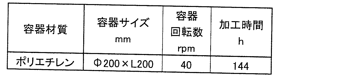
(試料6~試料10;比較例2)
さらに比較例として、主な構成材料が酸化アルミニウムである加工材を用いて上記実施例1および比較例2と同様にボールミル処理を行い、試料6~試料10の窒化珪素ころを得た。つまり、試料6~試料10の窒化珪素ころは、加工材以外は試料1~試料5の窒化珪素ころと同等の条件で作製されたものである。
さらに比較例として、主な構成材料が酸化アルミニウムである加工材を用いて上記実施例1および比較例2と同様にボールミル処理を行い、試料6~試料10の窒化珪素ころを得た。つまり、試料6~試料10の窒化珪素ころは、加工材以外は試料1~試料5の窒化珪素ころと同等の条件で作製されたものである。
具体的には、円柱状体は、窒化珪素を80体積%以上98体積%以下含んでおり、砥粒にダイヤモンドを用いて研磨加工されたものとした。加工材2は、酸化アルミニウムを80体積%以上98体積%以下含んだ球状体とした。加工材2の外径は7mm以上12mm以下とした。
さらに、試料1~試料4の窒化珪素ころと同様に、表1および表2に示す条件で、複数の円柱状体と、主な構成材料が酸化アルミニウムである複数の加工材と、水と、Fe2O3、CrO2、CeO2、Al2O3のいずれか1つとをボールミル容器に収容してボールミル処理を行い、試料6~試料9の窒化珪素ころを作製した。また、試料5の窒化珪素ころと同様に、複数の円柱状体と、主な構成材料が酸化アルミニウムである複数の加工材と、水とをボールミル容器に収容してボールミル処理を行い、試料10の窒化珪素ころを作製した。
このようにして得られた試料1~試料10の窒化珪素ころに対し、軸方向に垂直な断面における真円度、クラウニングドロップ量L1(図2参照)、クラウニング長さL2(図2参照)、外径面の表面粗さ(Ra)、端面の表面粗さ(Ra)、および寸法を測定した。さらに、軸の延在方向における外径面の長さL3に対するクラウニング長さL2の比率L2/L3を算出した。表3に、主な構成材料が窒化珪素である加工材を用いてボールミル処理が施された試料1~試料5の窒化珪素ころに対する測定結果を上述したボールミル処理前の円柱状体の測定結果と合わせて示す。また、表4に、主な構成材料が酸化アルミニウムである加工材を用いてボールミル処理が施された試料6~試料10の窒化珪素ころに対する測定結果を上述したボールミル処理前の円柱状体の測定結果と合わせて示す。なお、クラウニング長さおよびクラウニングドロップ量は、試料1~試料10の窒化珪素ころの断面プロファイルを形状測定器(ミツトヨフォームトレーサー使用)により取得し、該断面プロファイルから算出した。図12に、試料3の断面プロファイルのデータを示す。図12の縦軸は窒化珪素ころの軸方向に垂直方向における基準面からの深さ(単位:μm)を示し、横軸は窒化珪素ころの軸方向における基準面からの距離(単位:mm)を示す。
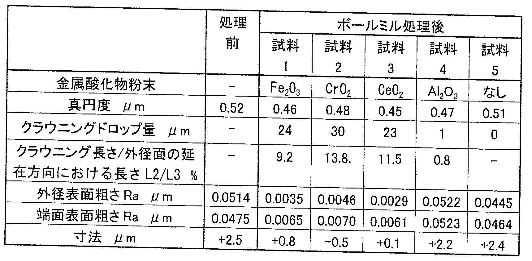
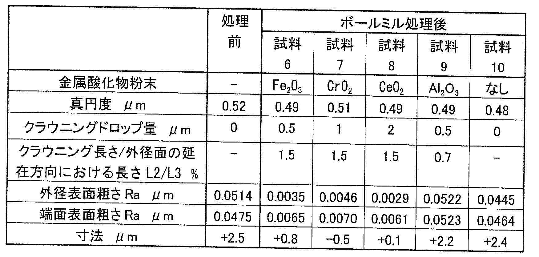
表3に示すように、母線の長さL3に対するクラウニング長さL2の比率は、それぞれ9.2%、13.8%、11.5%であった。つまり、試料1~試料3の窒化珪素ころにおける母線の長さL3に対するクラウニング長さL2の比率は9%以上25%以下であった。つまり、試料1~試料3の窒化珪素ころは、ころとしてエッジロードを回避するために十分なクラウニングが形成されていた。
さらに、試料1~試料3の窒化珪素ころの外径面および端面の各表面粗さ(Ra)は、ボールミル処理前の円柱状体時の外径面および端面の各表面粗さ(Ra)と比べて大きく低減されており、ころとして十分な表面粗さ(Ra)に改善されていた。一方で、ボールミル処理の前後で真円度等の形状精度に大きな変化は見られなかった。
図13に、試料2の窒化珪素ころにおける、クラウニングと外径面との境界部の表面の顕微鏡像を示す。また、図14に、試料2の窒化珪素ころの外径面の顕微鏡像を示す。図15に、試料2の窒化珪素ころの端面の顕微鏡像を示す。また、図16に、試料2の窒化珪素ころのクラウニング表面の顕微鏡像を示す。なお、比較例として、図17~図20に、ダイヤモンド砥石を用いたクラウニング加工(具体的には、砥石番手が#2000のダイヤモンド砥石を用いたスーパーフィニッシュ加工)が施された窒化珪素ころのクラウニングと外径面との境界部の表面、外径面、端面、およびクラウニング表面のそれぞれの顕微鏡像を示す。
従来のクラウニング加工が施された窒化珪素ころと比べて、試料2の窒化珪素ころはクラウニングと外径面との境界部の表面、外径面、端面、およびクラウニング表面のいずれの面においても傷や研磨痕が目立たなくなっていることが確認された。
これに対し、試料4および試料5の窒化珪素ころは、クラウニングドロップ量が1μm未満であって、母線の長さL3に対するクラウニング長さL2の比率は1.0%未満であり、ころとしてエッジロードを回避するために十分なクラウニングが形成されていなかった。特に、試料5の窒化珪素ころはクラウニングが形成されていなかった。試料4の窒化珪素ころの母線の長さL3に対するクラウニング長さL2の比率は0.8%であり、試料1~試料3の窒化珪素ころと比べて低かった。
また、試料5の窒化珪素ころの外径面および端面の各表面粗さ(Ra)はボールミル処理前と比較してわずかに小さくなっていたが、0.04μm以上あるため軸受寿命の低減抑制の観点から十分な改善は見られなかった。
また、試料4の窒化珪素ころは、外径面の表面粗さRa値がボールミル処理前の0.0514μmから0.0522μmに増大するとともに、端面の表面粗さRa値がボールミル処理前の0.0475μmから0.0523μmに増加していた。これは、窒化珪素からなる円柱状体と加工材とが摺接される際に、円柱状体の表面を高硬度の酸化アルミニウムが擦過することにより、該表面に傷や研磨痕が生じるためと考えられる。
つまり、実施例1および比較例1の結果から、主な構成材料が窒化珪素である円柱状体よりも低硬度の金属酸化物粉末と、円柱状体と同様に主な構成材料が窒化珪素である加工材とを用いてボールミル処理を行うことにより、軸方向の両端部にクラウニングが形成されているとともに、表面上の傷や研磨痕などの凹凸が十分に低減された窒化珪素ころを作製できることが確認された。また、真円度等の形状精度が十分に高められた円柱状体をボールミル処理することにより、形状精度が高く、かつクラウニングが形成されており、表面上の傷や研磨痕などが十分に低減された窒化珪素ころを得ることができることが確認された。
また、表4に示すように、試料6~試料10の窒化珪素ころは、クラウニングドロップ量が1μm未満であって、窒化珪素ころの母線の長さL3に対するクラウニング長さL2の比率は、それぞれ1.5%、1.5%、1.5%、0.7%であった。つまり、試料6~試料9の窒化珪素ころには、ころとしてエッジロードを回避するために十分なクラウニングが形成されていなかった。試料10の窒化珪素ころには、クラウニングが形成されていなかった。さらに、試料6~試料8の窒化珪素ころの外径面および端面の各表面粗さ(Ra)は、ボールミル処理前の円柱状体時の外径面および端面の各表面粗さ(Ra)と比べてわずかに小さくなっているが、0.03μm以上あるため軸受寿命の低減抑制の観点から十分な改善は見られなかった。また、試料9および試料10の窒化珪素ころの表面粗さについても、ボールミル処理前と同等かそれよりも大きく、軸受寿命の低減抑制の観点から十分な改善は見られなかった。
つまり、実施例1および比較例2の結果から、主な構成材料が円柱状体よりも高硬度の酸化アルミニウムである加工材を用いてボールミル処理を行った場合に、金属酸化物粉末の種類に依らず、十分なクラウニングが形成されず、かつ表面上の傷や研磨痕などの凹凸を十分に低減できないことが確認された。
実施の形態2に係る窒化珪素ころの製造方法に従って製造された窒化珪素ころについて、クラウニング部の寸法および表面粗さを測定した。
(試料11:実施例2)
まず、窒化珪素からなる円柱状体および加工材をそれぞれ複数個準備した。具体的には、円柱状体は、窒化珪素を80体積%以上98体積%以下含んでおり、砥粒にダイヤモンドを用いて研磨加工されたものとした。円柱状体の外径Φおよび長さLはいずれも13mmとした。準備した円柱状体は、外径面での表面粗さ(算術平均粗さ)Ra値は0.0514μmであり、端面での表面粗さRa値は0.0475μmであった。
まず、窒化珪素からなる円柱状体および加工材をそれぞれ複数個準備した。具体的には、円柱状体は、窒化珪素を80体積%以上98体積%以下含んでおり、砥粒にダイヤモンドを用いて研磨加工されたものとした。円柱状体の外径Φおよび長さLはいずれも13mmとした。準備した円柱状体は、外径面での表面粗さ(算術平均粗さ)Ra値は0.0514μmであり、端面での表面粗さRa値は0.0475μmであった。
また、加工材2は、窒化珪素を80体積%以上98体積%以下含んだ球状体とした。加工材2の外径は7mm以上12mm以下とした。
次に、準備した円柱状体1の軸方向における両端部にカットクラウニング6を形成した。カットクラウニング6は、砥面形状がカットクラウニング形状に設けられているダイヤモンド砥石を用いて円柱状体1を研削し、円柱状体1に該砥面形状を転写することにより形成した。図21に、円柱状体1のカットクラウニング6における断面プロファイルを示す。なお、断面プロファイルは、形状測定器(ミツトヨフォームトレーサー使用)を用いて取得した。
次に、図1に示すように、カットクラウニング6が形成された円柱状体1をボールミル(容器10)に収容し、これを回転させることにより円柱状体1と加工材2と分散媒3と金属酸化物粉末とを混合させた。具体的には、表1および表5に示す条件で、複数の円柱状体1、複数の加工材2、分散媒3としての水、および金属酸化物粉末としての酸化鉄(Fe2O3)をボールミル容器10に収容してボールミル処理を行った。ボールミル容器10は、実施例1で用いたボールミル容器10と同一のものを用いた。ボールミル処理の結果、試料11の窒化珪素ころ7を得た。図22に窒化珪素ころ7のクラウニング8における断面プロファイルと、図21に示したボールミル処理前の円柱状体1のカットクラウニング6における断面プロファイルを重ねて示す。

このようにして得られた試料11の窒化珪素ころに対し、軸方向に垂直な断面における真円度、クラウニングドロップ量L1(図3参照)、クラウニング長さL2(図3参照)、外径面の表面粗さ(Ra)、端面の表面粗さ(Ra)、および寸法を測定した。さらに、軸の延在方向における外径面の長さL3に対するクラウニング長さL2の比率L2/L3を算出した。表6に、主な構成材料が窒化珪素である加工材を用いてボールミル処理が施された試料11の窒化珪素ころに対する測定結果を上述したボールミル処理前の円柱状体の測定結果と合わせて示す。

表6および図22に示すように、試料11の窒化珪素ころは、クラウニングドロップ量が24μmであって、窒化珪素ころの母線の長さL3に対するクラウニング長さL2の比率は10.8%であり、ころとしてエッジロードを回避するために十分なクラウニングが形成されていた。また、試料11の窒化珪素ころの母線の長さL3に対するクラウニング長さL2の比率は、実施例1における試料1~試料3の窒化珪素ころの比率L2/L3と比べて大きかった。
また、図22を参照して、試料11の窒化珪素ころは実施例1における試料1の窒化珪素ころよりもクラウニング形状が対数曲線に近似しており、より理想的な形状を有するクラウニングが形成されていた。さらに、試料11の窒化珪素ころの外径面および端面の各表面粗さ(Ra)は、ボールミル処理前の円柱状体時の外径面および端面の各表面粗さ(Ra)と比べて大きく低減されており、ころとして十分な表面粗さ(Ra)に改善されていた。一方で、ボールミル処理の前後で真円度等の形状精度に大きな変化は見られなかった。
(試料12:比較例3)
また、比較例3として、バレル研磨により試料12の窒化珪素ころを得た。図23に試料12の成形体の断面プロファイルを示す。図22と比較して、試料12の成形体は外径面と端面との境界部において丸みが帯びているが、試料11の成形体のようなクラウニングは形成されていない。つまり、実施の形態1に係る窒化珪素ころの製造方法は、従来クラウニング加工方法として採用されていたバレル研磨法では形成するのが困難であったクラウニングを容易に形成することができる。
また、比較例3として、バレル研磨により試料12の窒化珪素ころを得た。図23に試料12の成形体の断面プロファイルを示す。図22と比較して、試料12の成形体は外径面と端面との境界部において丸みが帯びているが、試料11の成形体のようなクラウニングは形成されていない。つまり、実施の形態1に係る窒化珪素ころの製造方法は、従来クラウニング加工方法として採用されていたバレル研磨法では形成するのが困難であったクラウニングを容易に形成することができる。
実施の形態3に係る窒化珪素ころの製造方法に従って、窒化珪素ころについて外観検査を行った。
まず、窒化珪素からなり、長さLが13mm、外径Φが13mmの円柱状体を4種類準備した。具体的には、複数の円柱状体は、窒化珪素を80体積%以上98体積%以下含んでおり、砥粒にダイヤモンドを用いて研磨加工されたものとした。円柱状体の表面粗さ(算術平均粗さ)Ra値は0.01μmであった。当該研磨加工後、研磨面(表面)からの深さがそれぞれ50μm、80μm、120μm、150μmの位置に金属介在物欠陥(外形の最大幅が45μmのステンレス(SUS)粉を導入し、試料13~試料16の4種類の円柱状体を準備した。各円柱状体において金属介在物欠陥が導入された位置は、X線CT(Computed Tomography)機器を用いて研磨面から上記深さにあることを確認した。
試料13~試料16の円柱状体に対し、以下の検査方法により内部欠陥を検出可能であるか否かを評価した。第1の検査方法として、図9に示すように、拡大鏡として実体顕微鏡20を用いて試料13~試料16の円柱状体を目視検査する方法を採用した。また、第2の検査方法として、図10に示す検査系を用いて、試料13~試料16の円柱状体にレーザ光を照射したときに生じる反射光から、吸収率の変化を捉える方法を採用した。
さらに、試料13~試料16の円柱状体に対し、実施の形態1に係る窒化珪素ころの製造方法における円柱状体と加工材とを摺接させる工程(S20)に従ってボールミル処理を行った。なお、ボールミル処理は、試料13~試料16の円柱状体を含む、主な構成材料が窒化珪素である複数の円柱状体と、主な構成材料が窒化珪素である複数の加工材と、分散媒としての水と、金属酸化物粉末としての酸化鉄とをボールミル容器に収容し、上記表1および表2に示す条件で行った。なお、加工材は、窒化珪素を80体積%以上98体積%以下含んだ球状体とした。加工材2の外径は7mm以上12mm以下とした。
ボールミル処理後の試料13~試料16の成形体(窒化珪素ころ)に対し、ボールミル処理前と同様に上記第1および第2の検査方法により、内部欠陥を検出可能であるか否かを評価した。検査結果を表7に示す。
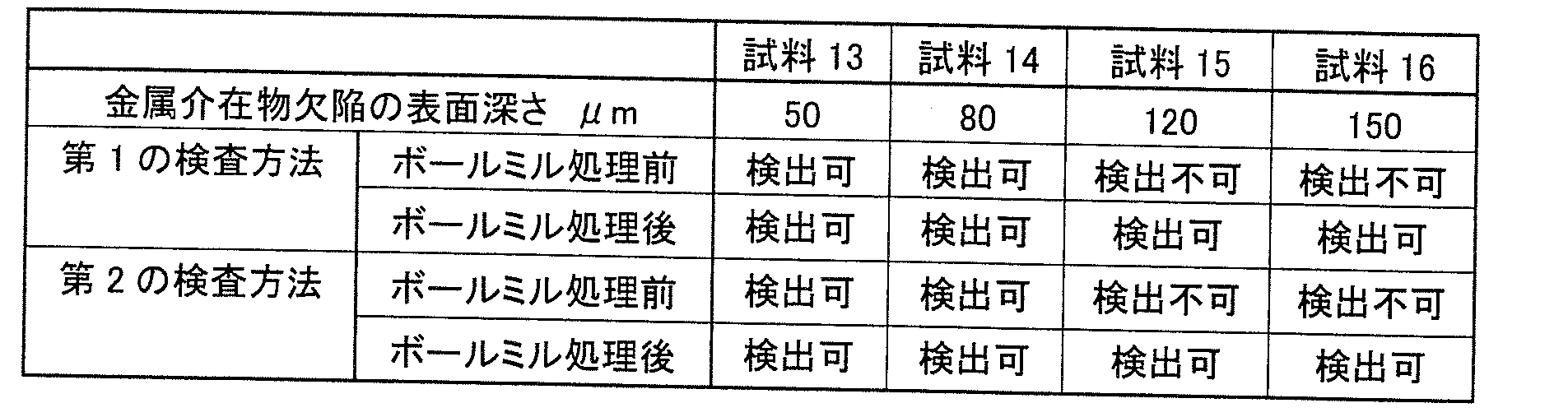
表7に示すように、金属介在物欠陥の表面深さが80μmよりも浅い試料13および試料14の円柱状体に対しては、ボールミル処理前であっても第1および第2の検査方法により当該金属介在物欠陥を検出することができた。しかし、金属介在物欠陥の表面深さが80μmよりも深く、ボールミル処理前の試料15および試料16の円柱状体に対しては、第1および第2の検査方法ともに当該金属介在物欠陥を検出することができなかった。
これに対し、ボールミル処理後の試料15および試料16の成形体に対しては、第1および第2の検査方法によっても当該金属介在物欠陥を検出することができた。これは、上述のようにボールミル処理前の円柱状体では表面の傷や研磨痕などの凹凸が形成されており、透過光が表面で散乱・減衰等されて表面から深い位置に存在する内部欠陥を検出することが困難であるのに対し、ボールミル処理後の成形体では表面の傷や研磨痕などの凹凸が十分に低減されているため、窒化珪素ころの表面での透過光の散乱・減衰等が抑制され表面から深い位置に存在する内部欠陥を検出することができると考えられる。
つまり、本実施例3の結果から、上記実施の形態3に係る窒化珪素ころの製造方法および上記実施の形態4に係る窒化珪素ころの検査方法により、成形体(窒化珪素ころ)に対して表面からより深い位置まで内部欠陥の有無を検査することができることが確認された。また、実施の形態4に係る窒化珪素ころの検査方法が、特に軸受用転動体用の窒化珪素ころの検査方法として特に好適であることが確認された。具体的には、窒化珪素ころを軸受用転動体として用いた場合、窒化珪素ころには転動面から120μm程度の領域までせん断応力が作用するため、当該領域に金属介在物欠陥などを有する窒化珪素ころは高信頼性が求められる軸受用転動体には不適である。これに対し、上記実施の形態4に係る窒化珪素ころの検査方法(実施の形態3に係る窒化珪素ころの製造方法)を実施することにより、転動面からの深さが少なくとも150μm程度の領域までの内部欠陥の有無を評価することができるため、転動面(ころの表面)からの深さが少なくとも150μm程度の領域において、所定の大きさの内部欠陥(たとえば外形の最大幅が25μm以上の欠陥が無い窒化珪素ころ(あるいは成形体)を選別することができる。
以上のように本発明の実施の形態について説明を行なったが、今回開示された実施の形態はすべての点で例示であって、制限的なものではないと考えられるべきである。本発明の範囲は請求の範囲によって示され、請求の範囲と均等の意味および範囲のすべての変更が含まれることが意図される。
本発明は、軸受用転動体に用いられる窒化珪素ころおよび窒化珪素ころの製造方法に特に有利に適用される。
1 円柱状体、2 加工材、3 分散媒、4,8 クラウニング、5,7 窒化珪素ころ、10 容器、11 ローラ。
Claims (12)
- 主な構成材料が窒化珪素であるころであって、
転動面を含み、軸を囲むように形成されている外径面を有し、
前記外径面の前記軸の延在方向における両端部にはそれぞれクラウニングが形成されており、
前記ころの表面からの深さが150μmよりも浅い領域において、外形の最大幅が25μm以上の欠陥が無い、窒化珪素ころ。 - 前記クラウニングは、主な構成材料が窒化珪素である複数の円柱状体と、主な構成材料が窒化珪素である複数の加工材と、前記円柱状体よりも低硬度の金属酸化物粉末と、分散媒とを混合して前記円柱状体と前記加工材とを摺接させることにより形成されており、
前記軸を含む前記窒化珪素ころの断面上において、前記外径面の前記延在方向における長さに対する前記クラウニングの前記延在方向における長さの比率は、それぞれ9%以上25%以下である、請求項1に記載の窒化珪素ころ。 - 主な構成材料が窒化珪素である複数の円柱状体と、主な構成材料が窒化珪素である複数の加工材と、前記円柱状体よりも低硬度の金属酸化物粉末と、分散媒とを準備する工程と、
複数の前記円柱状体と複数の前記加工材と前記金属酸化物粉末と前記分散媒とを混合することにより前記円柱状体と前記加工材とを摺接させる工程とを備える、窒化珪素ころの製造方法。 - 前記金属酸化物粉末は、酸化鉄、酸化クロム、および酸化セリウムからなる群から選択される少なくとも1つである、請求項3に記載の窒化珪素ころの製造方法。
- 前記摺接させる工程は、前記円柱状体と、前記加工材と、前記金属酸化物粉末と、前記分散媒とを容器に収容する工程と、
前記容器を動かすことにより前記円柱状体と前記加工材と前記金属酸化物粉末と前記分散媒とを混合する工程とを含む、請求項3または請求項4に記載の窒化珪素ころの製造方法。 - 前記容器は筒状体であり、前記混合する工程では、前記容器を回転させることにより前記円柱状体と前記加工材とを摺接させる、請求項5に記載の窒化珪素ころの製造方法。
- 前記加工材は球状体である、請求項3~請求項6のいずれか1項に記載の窒化珪素ころの製造方法。
- 前記摺接させる工程において、前記金属酸化物粉末は、前記分散媒1L当たり60g以上80g以下の割合で前記円柱状体と前記分散媒と混合されている、請求項3~請求項7のいずれか1項に記載の窒化珪素ころの製造方法。
- 前記摺接させる工程により前記円柱状体から得られた成形体を検査する工程をさらに備え、
前記成形体を検査する工程では、前記成形体に対して光を照射させ、前記成形体の少なくとも一部を透過した前記光を検出することにより、前記成形体の内部欠陥の有無を検査する、請求項3~請求項8のいずれか1項に記載の窒化珪素ころの製造方法。 - 前記成形体を検査する工程は、光が照射された前記成形体を拡大鏡を用いて目視検査することにより実施される、請求項9に記載の窒化珪素ころの製造方法。
- 前記成形体を検査する工程は、前記成形体にレーザ光を照射したときに生じる反射光から、反射率または吸収率の変化を捉えることにより実施される、請求項9に記載の窒化珪素ころの製造方法。
- 主な構成材料が窒化珪素である複数の円柱状体と、主な構成材料が窒化珪素である複数の加工材と、前記円柱状体よりも低硬度の金属酸化物粉末と、分散媒とを混合して前記円柱状体と前記加工材とを摺接させることにより前記円柱状体から形成された成形体を準備する工程と、
前記成形体に対して光を照射させ、前記成形体の少なくとも一部を透過した前記光を検出することにより、前記成形体の内部欠陥の有無を検査する工程とを備える、窒化珪素ころの検査方法。
Applications Claiming Priority (4)
| Application Number | Priority Date | Filing Date | Title |
|---|---|---|---|
| JP2015031555A JP2016153147A (ja) | 2015-02-20 | 2015-02-20 | 窒化珪素ころ、窒化珪素ころの製造方法、および窒化珪素ころの検査方法 |
| JP2015-031512 | 2015-02-20 | ||
| JP2015031512A JP2016153665A (ja) | 2015-02-20 | 2015-02-20 | 窒化珪素ころおよび窒化珪素ころの製造方法 |
| JP2015-031555 | 2015-02-20 |
Publications (1)
| Publication Number | Publication Date |
|---|---|
| WO2016133211A1 true WO2016133211A1 (ja) | 2016-08-25 |
Family
ID=56689359
Family Applications (1)
| Application Number | Title | Priority Date | Filing Date |
|---|---|---|---|
| PCT/JP2016/054938 Ceased WO2016133211A1 (ja) | 2015-02-20 | 2016-02-19 | 窒化珪素ころ、窒化珪素ころの製造方法、および窒化珪素ころの検査方法 |
Country Status (1)
| Country | Link |
|---|---|
| WO (1) | WO2016133211A1 (ja) |
Cited By (3)
| Publication number | Priority date | Publication date | Assignee | Title |
|---|---|---|---|---|
| CN109590816A (zh) * | 2018-12-25 | 2019-04-09 | 广东劲胜智能集团股份有限公司 | 一种陶瓷手机中框抛光方法 |
| WO2023238364A1 (ja) * | 2022-06-10 | 2023-12-14 | 株式会社ジェイテクト | 軸受用ころの製造方法 |
| EP4667762A1 (en) * | 2024-06-20 | 2025-12-24 | NTN Corporation | Roller and roller bearing |
Citations (4)
| Publication number | Priority date | Publication date | Assignee | Title |
|---|---|---|---|---|
| JPH04223865A (ja) * | 1990-12-27 | 1992-08-13 | Ntn Corp | 機械部品の加工方法 |
| JPH09280253A (ja) * | 1996-04-09 | 1997-10-28 | Honda Motor Co Ltd | セラミックス製ベアリング用転動体,同表面加工方法及び同表面加工装置 |
| WO2011083624A1 (ja) * | 2010-01-07 | 2011-07-14 | 株式会社ニッカトー | セラミック焼結体、セラミック球体およびセラミック球体検査装置 |
| JP2011148023A (ja) * | 2010-01-20 | 2011-08-04 | Sintokogio Ltd | 硬質金属材料の平滑研磨方法 |
-
2016
- 2016-02-19 WO PCT/JP2016/054938 patent/WO2016133211A1/ja not_active Ceased
Patent Citations (4)
| Publication number | Priority date | Publication date | Assignee | Title |
|---|---|---|---|---|
| JPH04223865A (ja) * | 1990-12-27 | 1992-08-13 | Ntn Corp | 機械部品の加工方法 |
| JPH09280253A (ja) * | 1996-04-09 | 1997-10-28 | Honda Motor Co Ltd | セラミックス製ベアリング用転動体,同表面加工方法及び同表面加工装置 |
| WO2011083624A1 (ja) * | 2010-01-07 | 2011-07-14 | 株式会社ニッカトー | セラミック焼結体、セラミック球体およびセラミック球体検査装置 |
| JP2011148023A (ja) * | 2010-01-20 | 2011-08-04 | Sintokogio Ltd | 硬質金属材料の平滑研磨方法 |
Cited By (5)
| Publication number | Priority date | Publication date | Assignee | Title |
|---|---|---|---|---|
| CN109590816A (zh) * | 2018-12-25 | 2019-04-09 | 广东劲胜智能集团股份有限公司 | 一种陶瓷手机中框抛光方法 |
| WO2023238364A1 (ja) * | 2022-06-10 | 2023-12-14 | 株式会社ジェイテクト | 軸受用ころの製造方法 |
| JPWO2023238364A1 (ja) * | 2022-06-10 | 2023-12-14 | ||
| JP7798192B2 (ja) | 2022-06-10 | 2026-01-14 | 株式会社ジェイテクト | 軸受用ころの製造方法 |
| EP4667762A1 (en) * | 2024-06-20 | 2025-12-24 | NTN Corporation | Roller and roller bearing |
Similar Documents
| Publication | Publication Date | Title |
|---|---|---|
| US8721392B2 (en) | Glass edge finishing method | |
| Suratwala et al. | Sub-surface mechanical damage distributions during grinding of fused silica | |
| CN103226108B (zh) | 表面检查方法和表面检查装置 | |
| Cheng et al. | Subsurface damages of fused silica developed during deterministic small tool polishing | |
| CN103158060A (zh) | 研磨刷、玻璃基板的端面研磨方法、及玻璃基板的制造方法 | |
| Zhong | Surface finish of precision machined advanced materials | |
| WO2016133211A1 (ja) | 窒化珪素ころ、窒化珪素ころの製造方法、および窒化珪素ころの検査方法 | |
| TW201209002A (en) | Synthetic quartz glass substrate and making method | |
| Wang et al. | Experimental investigation of subsurface damage depth of lapped optics by fluorescent method | |
| JP2016153147A (ja) | 窒化珪素ころ、窒化珪素ころの製造方法、および窒化珪素ころの検査方法 | |
| Xie et al. | Ultra-precise surface processing of LYSO scintillator crystals for Positron Emission Tomography | |
| Kuzin et al. | Correlation of diamond grinding regimes with Al2O3–TiC-ceramic surface condition | |
| JP2016153665A (ja) | 窒化珪素ころおよび窒化珪素ころの製造方法 | |
| JP2016078197A (ja) | 窒化珪素球状体、窒化珪素球状体の製造方法、および窒化珪素球状体の検査方法 | |
| JP2015104771A (ja) | 磁気ディスク用ガラス基板の製造方法及び研磨処理用キャリア | |
| JP2003269468A (ja) | ころ軸受 | |
| Dong et al. | Developing a trend prediction model of subsurface damage for fixed-abrasive grinding of optics by cup wheels | |
| Zhao et al. | Grinding damage of BK7 using copper-resin bond coarse-grained diamond wheel | |
| JP2015123553A (ja) | キャリア、キャリアの製造方法、および磁気ディスク用ガラス基板の製造方法 | |
| Kang et al. | The deterioration characteristics and mechanism of polishing pads in chemical mechanical polishing of fused silica | |
| Patel et al. | Effect of various parameters on material removal rate in flashing operation of precision steel ball manufacturing process | |
| CN1315116C (zh) | 用于信息记录介质的玻璃衬底及其制造方法 | |
| CN102825534A (zh) | 支撑夹具和制造磁性记录介质用玻璃基板的方法 | |
| CN115722985A (zh) | 一种低碳高合金钢制轴承外圈沟道磨削加工方法 | |
| US7987610B2 (en) | Method of examining aperture diameter of disk substrate having circular aperture in central portion thereof and apparatus thereof |
Legal Events
| Date | Code | Title | Description |
|---|---|---|---|
| 121 | Ep: the epo has been informed by wipo that ep was designated in this application |
Ref document number: 16752597 Country of ref document: EP Kind code of ref document: A1 |
|
| NENP | Non-entry into the national phase |
Ref country code: DE |
|
| 122 | Ep: pct application non-entry in european phase |
Ref document number: 16752597 Country of ref document: EP Kind code of ref document: A1 |