WO2016132856A1 - コネクタ - Google Patents
コネクタ Download PDFInfo
- Publication number
- WO2016132856A1 WO2016132856A1 PCT/JP2016/052606 JP2016052606W WO2016132856A1 WO 2016132856 A1 WO2016132856 A1 WO 2016132856A1 JP 2016052606 W JP2016052606 W JP 2016052606W WO 2016132856 A1 WO2016132856 A1 WO 2016132856A1
- Authority
- WO
- WIPO (PCT)
- Prior art keywords
- press
- press contact
- wire
- twisted pair
- pair
- Prior art date
- Legal status (The legal status is an assumption and is not a legal conclusion. Google has not performed a legal analysis and makes no representation as to the accuracy of the status listed.)
- Ceased
Links
Images




Classifications
-
- H—ELECTRICITY
- H01—ELECTRIC ELEMENTS
- H01R—ELECTRICALLY-CONDUCTIVE CONNECTIONS; STRUCTURAL ASSOCIATIONS OF A PLURALITY OF MUTUALLY-INSULATED ELECTRICAL CONNECTING ELEMENTS; COUPLING DEVICES; CURRENT COLLECTORS
- H01R4/00—Electrically-conductive connections between two or more conductive members in direct contact, i.e. touching one another; Means for effecting or maintaining such contact; Electrically-conductive connections having two or more spaced connecting locations for conductors and using contact members penetrating insulation
- H01R4/24—Connections using contact members penetrating or cutting insulation or cable strands
- H01R4/2416—Connections using contact members penetrating or cutting insulation or cable strands the contact members having insulation-cutting edges, e.g. of tuning fork type
- H01R4/242—Connections using contact members penetrating or cutting insulation or cable strands the contact members having insulation-cutting edges, e.g. of tuning fork type the contact members being plates having a single slot
- H01R4/2425—Flat plates, e.g. multi-layered flat plates
- H01R4/2429—Flat plates, e.g. multi-layered flat plates mounted in an insulating base
-
- H—ELECTRICITY
- H01—ELECTRIC ELEMENTS
- H01R—ELECTRICALLY-CONDUCTIVE CONNECTIONS; STRUCTURAL ASSOCIATIONS OF A PLURALITY OF MUTUALLY-INSULATED ELECTRICAL CONNECTING ELEMENTS; COUPLING DEVICES; CURRENT COLLECTORS
- H01R4/00—Electrically-conductive connections between two or more conductive members in direct contact, i.e. touching one another; Means for effecting or maintaining such contact; Electrically-conductive connections having two or more spaced connecting locations for conductors and using contact members penetrating insulation
- H01R4/24—Connections using contact members penetrating or cutting insulation or cable strands
- H01R4/2416—Connections using contact members penetrating or cutting insulation or cable strands the contact members having insulation-cutting edges, e.g. of tuning fork type
- H01R4/2445—Connections using contact members penetrating or cutting insulation or cable strands the contact members having insulation-cutting edges, e.g. of tuning fork type the contact members having additional means acting on the insulation or the wire, e.g. additional insulation penetrating means, strain relief means or wire cutting knives
- H01R4/245—Connections using contact members penetrating or cutting insulation or cable strands the contact members having insulation-cutting edges, e.g. of tuning fork type the contact members having additional means acting on the insulation or the wire, e.g. additional insulation penetrating means, strain relief means or wire cutting knives the additional means having two or more slotted flat portions
-
- H—ELECTRICITY
- H01—ELECTRIC ELEMENTS
- H01R—ELECTRICALLY-CONDUCTIVE CONNECTIONS; STRUCTURAL ASSOCIATIONS OF A PLURALITY OF MUTUALLY-INSULATED ELECTRICAL CONNECTING ELEMENTS; COUPLING DEVICES; CURRENT COLLECTORS
- H01R4/00—Electrically-conductive connections between two or more conductive members in direct contact, i.e. touching one another; Means for effecting or maintaining such contact; Electrically-conductive connections having two or more spaced connecting locations for conductors and using contact members penetrating insulation
- H01R4/70—Insulation of connections
-
- H—ELECTRICITY
- H01—ELECTRIC ELEMENTS
- H01R—ELECTRICALLY-CONDUCTIVE CONNECTIONS; STRUCTURAL ASSOCIATIONS OF A PLURALITY OF MUTUALLY-INSULATED ELECTRICAL CONNECTING ELEMENTS; COUPLING DEVICES; CURRENT COLLECTORS
- H01R13/00—Details of coupling devices of the kinds covered by groups H01R12/70 or H01R24/00 - H01R33/00
- H01R13/646—Details of coupling devices of the kinds covered by groups H01R12/70 or H01R24/00 - H01R33/00 specially adapted for high-frequency, e.g. structures providing an impedance match or phase match
- H01R13/6461—Means for preventing cross-talk
- H01R13/6463—Means for preventing cross-talk using twisted pairs of wires
Definitions
- the present invention relates to a connector.
- Patent Document 1 discloses a connector in which two press contact terminals are provided side by side on a housing and two wires constituting a twisted pair wire are connected to separate press contact terminals. This connector is used as a joint connector for branching two twisted pair wires.
- the twisted pair wire is twisted in a spiral shape with two electric wires approaching each other. Therefore, when performing pressure contact with the two pressure contact terminals, in order to individually correspond the two wires to the two pressure contact terminals, the twisting of the two wires is performed in advance and the two wires are separated. Need to do.
- the present invention has been completed based on the above situation, and an object thereof is to reduce the number of work steps when the twisted pair wire is pressed.
- the connector of the present invention Two press-contact terminal fittings in which the electric wires constituting the twisted pair wires are individually pressed, A holder for holding the two press contact terminal fittings so that the press contact portion formed on the press contact terminal fitting is aligned in a direction intersecting with a wiring direction of the twisted pair wires; A distribution rib formed on the holder and separating the two electric wires so as to correspond to the two pressure contact portions in the process of approaching the twisted pair wire to the pressure contact position with the pressure contact portion. Has characteristics.
- the two wires are separated by the distribution rib so as to correspond to the pressure contact portion.
- the number of work steps can be reduced.
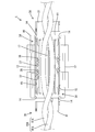
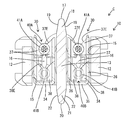
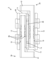
- Example 1 Plan view showing the state where the wires are distributed by the distribution ribs
- Side view showing the state in which the electric wires are distributed by the distribution ribs
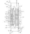
- Enlarged cross-sectional view showing the state in which the electric wires are distributed by the distribution ribs
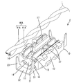
- Perspective view showing the state before distributing the wires
- a perspective view showing a state in which the electric wire is press-contacted to the press-contact portion.
- Enlarged cross-sectional view showing the state where the wire is in pressure contact Top view of connector Bottom view of connector
- a guide portion having a wedge-shaped cross section that is narrower toward a distal end side in the protruding direction may be formed on the sorting rib. According to this configuration, the two electric wires can be reliably separated by interrupting the guide portion between the two electric wires.
- the press contact portion includes two pairs of press contact blades arranged at intervals in the wiring direction of the twisted pair wire, and the distribution rib in the wiring direction of the twisted pair wire.
- the forming region may be the same as or wider than the range including the two pairs of press contact blades. According to this structure, an electric wire can be reliably press-contacted with respect to two pairs of press-contacting blades.
- the connector according to the present invention includes a pair of support plate portions in which the press contact portions rise from both side edges of the substrate portion and are opposed to each other, and a press contact blade that protrudes from the opposing surfaces of the pair of support plate portions to form a pair.
- the distribution rib is configured to rise in substantially the same direction as the support plate portion, and in the rising direction of the support plate portion, the distribution rib is positioned higher than the rising edge of the support plate portion. You may stand up. According to this configuration, the two electric wires can be reliably separated before being inserted between the pair of support plate portions.
- the press contact portion includes a press contact blade that sandwiches the electric wire in a pair, and the press contact blade makes the pair by slidingly contacting the electric wire.
- a guide edge portion that is guided in between may be formed, and the sliding contact surface of the electric wire in the distribution rib and the guide edge portion may be arranged to form an obtuse angle. According to this configuration, the two electric wires separated by the distributing rib can smoothly enter between the press contact blades.
- the connector C uses the first twisted pair wire 40A (the twisted pair wire described in the claims) and the second twisted pair wire 40B (the twisted pair wire described in the claims) as the objects to be pressed.
- the first twisted pair wire 40A is obtained by twisting two first electric wires 41A (electric wires described in claims) close to each other while twisting them in a spiral shape.
- the second twisted pair wire 40B is also obtained by twisting the two second electric wires 41B (electric wires described in claims) while twisting them in a spiral shape.
- the connector C has a function as a pressure contact type joint connector C for connecting the first twisted pair wire 40A and the second twisted pair wire 40B, and realizes a reduction in work man-hours when the two twisted pair wires 40A, 40B are pressed. It is.
- the arrangement direction of the twisted pair wires 40A and 40B in the pressure contact area with the pressure contact terminal fitting 30 is defined as the front-rear direction.
- the first twisted pair wire 40A is attached and connected to the connector C from above, and the second twisted pair wire 40B is assembled and connected to the connector C from below.
- the connector C connects the first electric wire 41A constituting the first twisted pair wire 40A and the second electric wire 41B constituting the second twisted pair wire 40B so as to be conductive, and constitutes the first twisted pair wire 40A.
- the other first electric wire 41A and the other second electric wire 41B constituting the second twisted pair wire 40B are connected so as to be conductive.
- each of the electric wires 41 ⁇ / b> A and 41 ⁇ / b> B is a known one in which a conductor 42 is surrounded by an insulating coating 43.
- the connector C includes a holder 10 and a pair of press contact terminal fittings 30.
- the holder 10 is made of synthetic resin, and has a pair of end wall portions 11 that are opposed to each other with a space in the front-rear direction, and a pair of left and right side wall portions 12 that connect the left and right edges of the pair of end wall portions 11.
- a single component including a single partition wall 13 that connects the central portions of the pair of end wall portions 11 in the left-right direction.
- the side wall part 12 and the partition part 13 are extended long in the front-back direction. As shown in FIGS.
- a pair of left and right concave portions 14 each having a substantially semicircular shape are formed on the upper end edge and the lower end edge of the end wall portion 11.
- the concave portion 14 positions the electric wire in the left-right direction and regulates upward or downward displacement.
- the left and right two spaces surrounded by the wall portions 11, 12, and 13 in the holder 10 are a pair of left and right mounting spaces that are long in the front-rear direction and open on both the upper and lower sides. It is 15.
- Each attachment space 15 accommodates a pressure contact portion 34 to be described later.
- a beam portion 16 is disposed between the front and rear end wall portions 11. The beam portion 16 restricts the electric wire press-contacted to an upper press-contact blade 37 described later from being displaced downward, and restricts the electric wire press-contacted to the lower press-contact blade 38 from being displaced upward.
- the partition wall portion 13 is located between the two pressure contact portions 34 accommodated in the two mounting spaces 15.
- the partition wall 13 has an upper distribution rib 17 (upward distribution rib) configured to protrude upward from an upper end edge thereof and a lower distribution rib 20 (downward configuration) protruded downward from the lower end edge of the partition wall section 13.
- the upper distribution rib 17 and the lower distribution rib 20 are vertically symmetrical.
- the formation region of the upper and lower sorting ribs 17 and 20 in the front-rear direction includes a formation region of four pairs of press contact blades 37 and 38, which will be described later, and includes a region in front and rear of the four pairs of press contact blades 37 and 38. It is over.
- the upper distributing rib 17 has an upper guide portion 18 having a wedge-shaped cross section that narrows toward the upper side (the leading end side in the protruding direction of the upper distributing rib 17). Is formed.
- the upper guide portion 18 is formed over the entire region in the vertical direction (projection direction) of the upper distribution rib 17.
- the left and right outer surfaces of the upper guide portion 18 are upper slidable contact surfaces 19 (slidable contact surfaces described in claims).
- the lower distribution rib 20 is also formed with a lower guide portion 21 (a guide portion according to the claims) having a wedge-shaped cross section that narrows downward (toward the front end side in the protruding direction of the lower distribution rib 20).
- the lower guide portion 21 is also formed over the entire region in the vertical direction (protruding direction) of the lower sorting rib 20, similarly to the upper guide portion 18.
- the left and right outer surfaces of the lower guide portion 21 are lower sliding contact surfaces 22.
- the pair of press contact terminal fittings 30 have the same shape and dimensions, and are arranged so as to be point symmetric in plan view, as shown in FIGS.
- the press-contact terminal fitting 30 is a single part including an electric wire holding portion 31 and a press-contact portion 34 that is elongated from the electric wire holding portion 31 forward.
- the electric wire holding portion 31 includes a horizontal receiving plate portion 32 having a substantially square shape in plan view, and a pair of crimping pieces 33 rising from both left and right edges of the receiving plate portion 32.
- the press contact portion 34 is elongated vertically and horizontally from the right end portion of the front end edge of the receiving plate portion 32, and upwards at substantially right angles from the left and right side edges of the substrate portion 35.
- a pair of support plate portions 36 rising in a cantilever manner and four pairs of press contact blades 37 and 38 are provided.
- the pair of press contact blades 37, 38 have a shape that protrudes inward in a substantially V shape in plan view by bending a part of both the left and right support plate portions 36.
- the upper end edge of the upper press contact blade 37 is an upper guide edge portion 37E (guide edge portion described in claims) inclined with respect to the vertical direction (the press contact direction of the electric wire with respect to the upper press contact blade 37).
- the upper edge of the lower press contact blade 38 is a lower guide edge 38E inclined with respect to the vertical direction (the press contact direction of the electric wire with respect to the lower press contact blade 38).
- the four pairs of press contact blades 37 and 38 are arranged in two upper and lower stages.
- the two pairs of upper press contact blades 37 disposed on the upper side are disposed at a predetermined interval in the front and rear direction.
- Two pairs of lower press-contacting blades 38 arranged on the lower side are also arranged at a predetermined interval in the front-rear direction.
- the front upper press-contact blade 37 and the front lower press-contact blade 38 are arranged so as to be displaced in the front-rear direction.
- the rear upper press-contact blade 37 and the rear lower press-contact blade 38 are also displaced in the front-rear direction.
- the two press contact terminal fittings 30 are assembled to the holder 10 from below, and each press contact portion 34 is accommodated in the mounting space 15.
- the upper sorting rib 17 is positioned above the upper end edge of the support plate portion 36 and rises in the same direction as the rising direction of the support plate portion 36.
- the lower end portion of the upper sliding contact surface 19 is at the upper end portion of the upper guide edge portion 37E of the upper press contact blade 37 on the inner side (side closer to the partition wall portion 13 and the upper distribution rib 17) of the pair of upper press contact blades 37.
- they are positioned so that they form an obtuse angle and line up close to each other.
- the assembly of the holder 10 and the press contact terminal fitting 30 is performed in parallel with the press contact process of the press contact terminal fitting 30 and the electric wires 41A and 41B.
- the two second electric wires 41 ⁇ / b> B constituting the second twisted pair wire 40 ⁇ / b> B are distributed to the left and right by the lower distribution rib 20.
- the lower end edge of the lower sorting rib 20 is inserted into the gap between the two second electric wires 41B that are twisted together.
- the two second electric wires 41B are gradually slidably brought into mutual contact with the lower slidable contact surface 22 by the lower guide portion 21 of the lower guide portion 21 that becomes gradually wider. Increase the interval. Then, the two second electric wires 41 ⁇ / b> B that have passed through the lower distribution rib 20 are accommodated in the attachment space 15, respectively.
- the two pressure contact portions 34 are accommodated in the mounting space 15 from below the holder 10, respectively.
- the two second electric wires 41B are pushed upward by coming into contact with the upper guide edge 37E of the upper press contact blade 37, respectively.
- the second electric wire 41B is restricted from being displaced upward by coming into contact with the beam portion 16, the two pairs of upper press contact blades 37 pass through the second electric wire 41B.
- the two pairs of lower pressure contact blades 38 are pressed against the second electric wire 41B so as to be sandwiched from the left and right.
- the pair of lower press-contacting blades 38 are in contact with the conductor 42 so as to be sandwiched from both the left and right sides by cutting the insulating coating 43.
- the two second electric wires 41B constituting the second twisted pair wire 40B are separately pressed against the two press contact terminal fittings 30 and the two press contact terminal fittings 30 are assembled to the holder 10.
- the electric wire holding portion 31 is positioned so as to correspond to the end wall portion 11 outside the attachment space 15.
- the two first electric wires 41A constituting the first twisted pair wire 40A are pressed against the two press contact portions 34 while being distributed to the left and right.
- the upper end edge of the upper distribution rib 17 is inserted into the gap between the two first electric wires 41A.
- the two first electric wires 41A are moved upward by the upper guide portion 18 of the upper guide portion 18 that becomes gradually wider. Gradually increase the distance between each other while sliding.
- the two first electric wires 41 ⁇ / b> A that have passed through the upper distribution rib 17 are accommodated in the attachment space 15, respectively.
- the first electric wire 41 ⁇ / b> A moves from the lower end portion of the upper sliding contact surface 19 to the upper guide edge portion 37 ⁇ / b> E of the upper press contact blade 37.
- the upper slidable contact surface 19 and the upper guide edge 37E are arranged close to each other at an obtuse angle, the first electric wire 41A can be separated from the upper slidable contact surface 19 without being caught. Smooth transition to 37E.
- One first electric wire 41 ⁇ / b> A is in pressure contact with the press contact portion 34 of the one press contact terminal fitting 30, and the other first electric wire 41 ⁇ / b> A is press contacted with the press contact portion 34 of the other press contact terminal fitting 30.
- the first electric wire 41 ⁇ / b> A is pushed between the two pairs of upper and lower upper press contact blades 37.
- the pair of upper press contact blades 37 are in contact with the conductor 42 so as to be sandwiched from both the left and right sides by cutting the insulating coating 43.
- the two press contact portions 34 (pressure contact terminal fittings 30) and the two first electric wires 41A are individually connected so as to be conductive.
- one of the first electric wire 41A and the second twisted-pair wire 40B constituting the first twisted pair wire 40A are formed on one of the press-connecting terminal fittings 30 (the press-contacting portion 34).
- the second electric wire 41B is connected (joint) so as to be conductive.
- the other first electric wire 41A constituting the first twisted pair wire 40A and the other second electric wire 41B constituting the second twisted pair wire 40B can be electrically connected to the other press contact terminal fitting 30 (the press contact portion 34). Connected (joint).
- the four electric wires 41A and 41B are collectively held in each electric wire holding portion 31. That is, the four electric wires 41A and 41B (the first twisted pair wire 40A and the second twisted pair wire 40B) placed on the receiving plate portion 32 are surrounded by the two caulking pieces 33 that are paired on the left and right. As a result, the four electric wires 41 ⁇ / b> A and 41 ⁇ / b> B are held in pressure contact with the press contact portion 34, and the holder 10 and the two press contact terminal fittings 30 are fixed.
- the connector C of the present embodiment aims to reduce the work man-hours, and presses the two first electric wires 41A constituting the first twisted pair wire 40A individually and also constitutes the second twisted pair wire 40B.
- the holder 10 holding the two press contact terminal fittings 30 is arranged so that the press contact portions 34 formed on the press contact terminal fittings 30 are arranged in a direction intersecting with the wiring direction of the twisted pair wires 40A and 40B.
- the holder 10 has an upper distribution rib 17 that separates the two first electric wires 41 ⁇ / b> A so as to correspond to the two press contact portions 34 in the process of causing the first twisted pair wire 40 ⁇ / b> A to approach the press contact position with the press contact portion 34. It has. Therefore, when the first twisted pair wire 40 ⁇ / b> A is brought close to the press contact position with the press contact portion 34, the two first electric wires 41 ⁇ / b> A are separated so as to correspond to the press contact portion 34 by the upper distribution rib 17. As described above, according to the connector C of this embodiment, it is not necessary to separate the two first electric wires 41A in advance before the press-contacting process, so that the number of work steps can be reduced.
- the holder 10 is provided with lower distribution ribs 20 that separate the two second electric wires 41B so as to correspond to the two press contact portions 34 in the process of bringing the second twisted pair wire 40B closer to the press contact position with the press contact portion 34. I have. Therefore, when the second twisted pair wire 40 ⁇ / b> B is brought close to the press contact position with the press contact portion 34, the two second electric wires 41 ⁇ / b> B are separated by the lower distribution rib 20 so as to correspond to the press contact portion 34. As described above, according to the connector C of this embodiment, it is not necessary to separate the two second electric wires 41B in advance before the press-contacting process, so that the number of work steps can be reduced.
- the upper distribution rib 17 is formed with the upper guide portion 18 having a wedge-shaped cross section in which the width dimension in the arrangement direction of the pressure contact portions 34 is narrowed toward the tip (upper end), the two first electric wires 41A By interposing the upper guide portion 18 therebetween, the two first electric wires 41A can be reliably separated.
- the lower distribution rib 20 is also formed with the lower guide portion 21 having a wedge-shaped cross section in which the width dimension in the arrangement direction of the pressure contact portions 34 is narrowed toward the tip (lower end), and thus the two second electric wires 41B. By interposing the lower guide portion 21 between the two, the two second electric wires 41B can be reliably separated.
- the press contact portion 34 includes two pairs of upper press contact blades 37 arranged at intervals in the front-rear direction (wiring direction of the twisted pair wires 40A and 40B). And the formation area of the upper distribution rib 17 in the front-back direction extends over a wider range than the range including the two pairs of upper press contact blades 37.
- the two first electric wires 41 ⁇ / b> A when the two first electric wires 41 ⁇ / b> A are distributed to the left and right by the upper distributing rib 17, the two first electric wires 41 ⁇ / b> A cover a range including the formation region of the two pairs of upper press contact blades 37. Are separated. Therefore, following the step of distributing the first electric wire 41 ⁇ / b> A by the upper distributing rib 17, the first electric wire 41 ⁇ / b> A can be reliably pressed against the upper press contact blade 37.
- the press contact portion 34 includes a pair of support plate portions 36 that are arranged to face each other while rising from both side edges of the substrate portion 35, and upper press contact blades 37 that protrude from the opposing surfaces of the pair of support plate portions 36 to form a pair.
- the upper distribution rib 17 is configured to rise in substantially the same direction as the rising direction of the support plate portion 36. In the rising direction of the support plate part 36, the upper sorting rib 17 rises to a position higher than the rising edge of the support plate part 36. According to this configuration, the two first electric wires 41 ⁇ / b> A can be reliably separated before being inserted between the pair of support plate portions 36.
- the press contact portion 34 includes an upper press contact blade 37 that forms a pair and sandwiches the first electric wire 41A.
- the upper press contact blade 37 forms a pair by sliding the first electric wire 41A in sliding contact with the upper press contact blade 37.
- An upper guide edge portion 37E is formed to be guided therebetween.
- the upper sliding contact surface 19 with which the 1st electric wire 41A is slidably contacted in the upper distribution rib 17, and the upper guide edge 37E are arranged so that it may form in an obtuse angle. According to this configuration, the two first electric wires 41 ⁇ / b> A separated by the upper distribution rib 17 can smoothly enter between the upper press contact blades 37.
- the present invention is not limited to the embodiments described with reference to the above description and drawings.
- the following embodiments are also included in the technical scope of the present invention.
- the wedge-shaped cross-section guide portion is formed on the distribution rib in the above embodiment, the distribution rib may not have the wedge-shaped cross-section guide portion.
- the distribution area of the distribution ribs in the twisted pair wiring direction extends over a range wider than the range including the two pairs of upper press contact blades. The range may be the same as or narrower than the range including the upper press contact blade.
- the sliding contact surface of the upper distributing rib and the guide edge portion of the press contact blade are arranged so as to form an obtuse angle, but the sliding contact surface and the guide edge portion are arranged substantially at right angles. It may be arranged as follows.
- the sliding contact surface of the upper distributing rib and the guide edge of the press contact blade are arranged close to each other, but the sliding contact surface and the guide edge are arranged in a separated positional relationship. May be.
- two upper and lower distribution ribs are formed on one holder, but only one distribution rib or three or more distribution ribs may be formed on one holder.
- one press contact portion is formed on one press contact terminal fitting, but a plurality of press contact portions may be formed on one press contact terminal fixture.
- four pairs of press contact blades are formed on one press contact portion, but the number of press contact blades formed on one press contact portion may be three pairs or less, or five pairs or more.
- the press contact blades are formed at two different positions in the rising direction of the support plate portion, but the number of press contact blades arranged in the rising direction of the support plate portion may be three or more. The number of press contact blades arranged in the rising direction of the part may be only one.
- two press contact terminal fittings are attached to one holder, but the number of press contact terminal fittings attached to one holder may be one or three or more.
Landscapes
- Connections By Means Of Piercing Elements, Nuts, Or Screws (AREA)
- Multi-Conductor Connections (AREA)
- Connector Housings Or Holding Contact Members (AREA)
- Coupling Device And Connection With Printed Circuit (AREA)
- Manufacturing Of Electrical Connectors (AREA)
- Connections Effected By Soldering, Adhesion, Or Permanent Deformation (AREA)
Abstract
ツイストペア線を圧接する際の作業工数を削減する。 コネクタ(C)は、ツイストペア線(40A,40B)を構成する電線(41A,41B)が個別に圧接される2つの圧接端子金具(30)と、圧接端子金具(30)に形成された圧接部(34)が、ツイストペア線(40A,40B)の配索方向と交差する方向に並ぶように、2つの圧接端子金具(30)を保持するホルダ(10)と、ホルダ(10)に形成され、ツイストペア線(40A,40B)を圧接部(34)との圧接位置へ接近させる過程で、2本の電線(41A,41B)を2つの圧接部(34)と対応するように離間させる振分けリブ(37,38)とを備えている。
Description
本発明は、コネクタに関するものである。
特許文献1には、ハウジングに2つの圧接端子を左右に並べて設け、ツイストペア線を構成する2本の電線を、夫々、別々の圧接端子に接続させるコネクタが開示されている。このコネクタは、2つのツイストペア線を分岐させるためのジョイントコネクタとして用いられる。
ツイストペア線は2本の電線を接近させて螺旋状に捻ったものである。したがって、2つの圧接端子との圧接を行う際には、2本の電線を2つの圧接端子に個別に対応させるために、予め、2本の電線の捻りを戻し、2本の電線を引き離す作業を行う必要がある。
本発明は上記のような事情に基づいて完成されたものであって、ツイストペア線を圧接する際の作業工数を削減することを目的とする。
本発明のコネクタは、
ツイストペア線を構成する電線が個別に圧接される2つの圧接端子金具と、
前記圧接端子金具に形成された圧接部が、前記ツイストペア線の配索方向と交差する方向に並ぶように、前記2つの圧接端子金具を保持するホルダと、
前記ホルダに形成され、前記ツイストペア線を前記圧接部との圧接位置へ接近させる過程で、2本の前記電線を2つの前記圧接部と対応するように離間させる振分けリブとを備えているところに特徴を有する。
ツイストペア線を構成する電線が個別に圧接される2つの圧接端子金具と、
前記圧接端子金具に形成された圧接部が、前記ツイストペア線の配索方向と交差する方向に並ぶように、前記2つの圧接端子金具を保持するホルダと、
前記ホルダに形成され、前記ツイストペア線を前記圧接部との圧接位置へ接近させる過程で、2本の前記電線を2つの前記圧接部と対応するように離間させる振分けリブとを備えているところに特徴を有する。
ツイストペア線を圧接部との圧接位置へ接近させると、2本の電線が、振分けリブにより圧接部と対応するように離間させられる。このように、本発明によれば、圧接工程の前に予め2本の電線を離間させておく必要がないので、作業工数が少なくて済む。
(a)本発明のコネクタは、前記振分けリブには、その突出方向先端側に向かって幅狭となる楔状断面のガイド部が形成されていてもよい。この構成によれば、2本の電線の間にガイド部を割り込ませることにより、2本の電線を確実に離間させることができる。
(b)本発明のコネクタは、前記圧接部が、前記ツイストペア線の配索方向に間隔を空けて配された二対の圧接刃を備えており、前記ツイストペア線の配索方向における前記振分けリブの形成領域は、前記二対の圧接刃を含む範囲と同じか、それよりも広い範囲に亘っていてもよい。この構成によれば、電線を二対の圧接刃に対し確実に圧接させることができる。
(c)本発明のコネクタは、前記圧接部が、基板部の両側縁から立ち上がって対向配置された一対の支持板部と、前記一対の支持板部の対向面から突出して対をなす圧接刃とを備え、前記振分けリブは、前記支持板部とほぼ同じ方向へ立ち上がった形態であり、前記支持板部の立ち上がり方向において、前記振分けリブは、前記支持板部の立ち上がり端縁よりも高い位置まで立ち上がっていてもよい。この構成によれば、2本の電線を、一対の支持板部の間に挿入される前に、確実に離間させることができる。
(d)本発明のコネクタは、前記圧接部が、対をなして前記電線を挟む圧接刃を備えており、前記圧接刃には、前記電線を摺接させることで前記対をなす前記圧接刃間に誘導するガイド縁部が形成され、前記振分けリブにおける前記電線の摺接面と、前記ガイド縁部とが、鈍角をなして並ぶように配されていてもよい。この構成によれば、振分けリブによって離間させられた2本の電線が、円滑に圧接刃の間に進入することができる。
<実施例1>
以下、本発明を具体化した実施例1を図1~図9を参照して説明する。本実施例のコネクタCは、第1ツイストペア線40A(請求項記載のツイストペア線)と、第2ツイストペア線40B(請求項記載のツイストペア線)を圧接対象とする。第1ツイストペア線40Aは、2本の第1電線41A(請求項記載の電線)を捻りながら接近させて螺旋状に撚ったものである。第2ツイストペア線40Bも、第1ツイストペア線40Aと同様、2本の第2電線41B(請求項記載の電線)を捻りながら接近させて螺旋状に撚ったものである。コネクタCは、第1ツイストペア線40Aと第2ツイストペア線40Bを接続させる圧接タイプのジョイントコネクタCとしての機能を有し、両ツイストペア線40A,40Bを圧接する際の作業工数の削減を実現するものである。
以下、本発明を具体化した実施例1を図1~図9を参照して説明する。本実施例のコネクタCは、第1ツイストペア線40A(請求項記載のツイストペア線)と、第2ツイストペア線40B(請求項記載のツイストペア線)を圧接対象とする。第1ツイストペア線40Aは、2本の第1電線41A(請求項記載の電線)を捻りながら接近させて螺旋状に撚ったものである。第2ツイストペア線40Bも、第1ツイストペア線40Aと同様、2本の第2電線41B(請求項記載の電線)を捻りながら接近させて螺旋状に撚ったものである。コネクタCは、第1ツイストペア線40Aと第2ツイストペア線40Bを接続させる圧接タイプのジョイントコネクタCとしての機能を有し、両ツイストペア線40A,40Bを圧接する際の作業工数の削減を実現するものである。
尚、以下の説明では、便宜上、圧接端子金具30との圧接領域におけるツイストペア線40A,40Bの配索方向を、前後方向と定義する。また、第1ツイストペア線40AがコネクタCに対して上方から取り付けられて接続され、第2ツイストペア線40BがコネクタCに対して下方から組み付けられて接続されるものとする。
コネクタCは、第1ツイストペア線40Aを構成する一方の第1電線41Aと、第2ツイストペア線40Bを構成する一方の第2電線41Bとを導通可能に接続し、第1ツイストペア線40Aを構成する他方の第1電線41Aと、第2ツイストペア線40Bを構成する他方の第2電線41Bとを導通可能に接続する。図4に示すように、各電線41A,41Bは、導体42を絶縁被覆43で包囲した周知のものである。
図4,7~9に示すように、コネクタCは、ホルダ10と、一対の圧接端子金具30とを備えて構成されている。ホルダ10は、合成樹脂製であり、前後方向に間隔を開けて対向配置された一対の端壁部11と、一対の端壁部11の左右両端縁同士を連結する左右一対の側壁部12と、一対の端壁部11の左右方向中央部同士を連結する1つの隔壁部13とを備えた単一部品である。側壁部12と隔壁部13は、前後方向に長く延びている。図2,5に示すように、端壁部11の上端縁と下端縁には、夫々、略半円形をなす左右一対ずつの凹部14が形成されている。凹部14は、電線を、左右方向に位置決めするとともに、上方又は下方への変位を規制するものである。
図4,7~9に示すように、ホルダ10のうち上記各壁部11,12,13で囲まれた左右2つの空間は、前後方向に長く且つ上下両面が開放された左右一対の取付け空間15となっている。各取付け空間15内には、夫々、後述する圧接部34が収容されている。また、図4,7に示すように、各取付け空間15内には、夫々、前後両端壁部11の間に差し渡された梁部16が配されている。梁部16は、後述する上部圧接刃37に圧接された電線が下方へ変位することを規制するとともに、下部圧接刃38に圧接された電線が上方へ変位するのを規制する。
上記のように隔壁部13は、2つの取付け空間15内に収容される2つの圧接部34の間に位置する。そして、この隔壁部13には、その上端縁から上方へ突出した形態の上部振分けリブ17(請求項記載の振分けリブ)と、下端縁から下方へ突出した形態の下部振分けリブ20(請求項記載の振分けリブ)とが一体に形成されている。上部振分けリブ17と下部振分けリブ20は、上下対称な形状である。前後方向における上下両振分けリブ17,20の形成領域は、後述する四対の圧接刃37,38の形成領域を含み、且つ四対の圧接刃37,38よりも前方及び後方の領域を含む範囲に亘っている。
図4,7に示すように、上部振分けリブ17には、上方(上部振分けリブ17の突出方向先端側)に向かって幅狭となる楔状断面の上部ガイド部18(請求項記載のガイド部)が形成されている。上部ガイド部18は、上部振分けリブ17の上下方向(突出方向)における全領域に亘って形成されている。そして、この上部ガイド部18の左右両外側面は、上部摺接面19(請求項記載の摺接面)となっている。
下部振分けリブ20にも、上部振分けリブ17と同様、下方(下部振分けリブ20の突出方向先端側)に向かって幅狭となる楔状断面の下部ガイド部21(請求項記載のガイド部)が形成されている。下部ガイド部21も、上部ガイド部18と同様、下部振分けリブ20の上下方向(突出方向)における全領域に亘って形成されている。そして、この下部ガイド部21の左右両外側面は、下部摺接面22となっている。
一対の圧接端子金具30は、形状と寸法が同一であり、図8,9に示すように、平面視において点対称となるように配されている。圧接端子金具30は、電線保持部31と、電線保持部31から前方へ細長く延びた圧接部34とを備えた単一部品である。図1に示すように、電線保持部31は、平面視略方形をなす水平な受け板部32と、受け板部32の左右両側縁から立ち上がる一対のカシメ片33とから構成されている。
図4,7に示すように、圧接部34は、受け板部32の前端縁における右端部から前方へ細長く水平に延びた基板部35と、基板部35の左右両側縁から略直角に上方へ片持ち状に立ち上がる一対の支持板部36と、四対の圧接刃37,38とを備えて構成されている。図1,8に示すように、対をなす圧接刃37,38は、左右両支持板部36の一部を曲げ加工することにより内側へ平面視略V字形に突出した形態である。上部圧接刃37の上側の端縁は、上下方向(上部圧接刃37に対する電線の圧接方向)に対して傾斜した上部ガイド縁部37E(請求項に記載のガイド縁部)となっている。下部圧接刃38の上側の端縁は、上下方向(下部圧接刃38に対する電線の圧接方向)に対して傾斜した下部ガイド縁部38Eとなっている。
また、図4,7に示すように、四対の圧接刃37,38は、上下2段に分かれて配されている。上段側に配された二対の上部圧接刃37は、前後に所定の間隔を開けて配されている。下段側に配された二対の下部圧接刃38も、前後に所定の間隔を開けて配されている。そして、図8に示すように、前側の上部圧接刃37と前側の下部圧接刃38は、前後方向に位置ずれして配置されている。後側の上部圧接刃37と後側の下部圧接刃38も前後方向に位置ずれして配置されている。
2つの圧接端子金具30は、ホルダ10に対しその下方から組み付けられ、各圧接部34が、夫々、取付け空間15内に収容されている。圧接部34が取付け空間15に収容された状態では、上部振分けリブ17が、支持板部36の上端縁よりも上方に位置し、支持板部36の立ち上がり方向と同じ方向へ立ち上がっている。そして、上部摺接面19の下端部が、対をなす上部圧接刃37のうち内側(隔壁部13及び上部振分けリブ17に近い側)の上部圧接刃37の上部ガイド縁部37Eの上端部に対し、鈍角をなして上下に接近して並ぶように位置している。
次に、本実施例の作用を説明する。ホルダ10と圧接端子金具30との組付けは、圧接端子金具30と電線41A,41Bの圧接工程と並行して行われる。組付けに際しては、まず、第2ツイストペア線40Bを構成する2本の第2電線41Bを、下部振分けリブ20によって左右に振り分ける。このとき、撚り合わされている2本の第2電線41Bの隙間に、下部振分けリブ20の下端縁を割り込ませるようにする。そして、第2ツイストペア線40Bを上方へ移動させると、2本の第2電線41Bが、次第に幅広となる下部ガイド部21の下部ガイド部21により、下部摺接面22に摺接しながら次第に互いの間隔を広げていく。そして、下部振分けリブ20を通過した2本の第2電線41Bは、夫々、取付け空間15内に収容される。
この後、2つの圧接部34を、夫々、ホルダ10の下方から取付け空間15内に収容する。収容する過程では、2本の第2電線41Bが、夫々、上部圧接刃37の上部ガイド縁部37Eに当接して上方へ押し上げられる。しかし、第2電線41Bは、梁部16に当接することによって上方への変位を規制されているので、二対の上部圧接刃37が第2電線41Bを通過する。さらに、取付け空間15に圧接部34を押し込む作業を進めると、前後二対の下部圧接刃38が、第2電線41Bに対し左右から挟むように圧接される。対をなす下部圧接刃38は、絶縁被覆43を切開して導体42に対し左右両側から挟むように当接する。
これにより、第2ツイストペア線40Bを構成する2本の第2電線41Bが、2つの圧接端子金具30に別々に圧接されるとともに、2つの圧接端子金具30がホルダ10に組み付けられる。この状態では、電線保持部31が、取付け空間15の外部において端壁部11と対応するように位置する。
この後は、第1ツイストペア線40Aを構成する2本の第1電線41Aを、左右に振り分けながら、2つの圧接部34に圧接する。このとき、2本の第1電線41Aの隙間に上部振分けリブ17の上端縁を割り込ませるようにする。そして、第1ツイストペア線40Aを下方へ移動させると、図4に示すように、2本の第1電線41Aが、次第に幅広となる上部ガイド部18の上部ガイド部18により、上部摺接面19に摺接しながら次第に互いの間隔を広げていく。そして、上部振分けリブ17を通過した2本の第1電線41Aは、夫々、取付け空間15内に収容される。
取付け空間15内に収容される際に、第1電線41Aは、上部摺接面19の下端部から上部圧接刃37の上部ガイド縁部37Eに移行する。ここで、上部摺接面19と上部ガイド縁部37Eは、鈍角をなして接近して並んでいるので、第1電線41Aは、引っ掛かり等を生じることなく上部摺接面19から上部ガイド縁部37Eへ円滑に移行する。そして、一方の第1電線41Aは一方の圧接端子金具30の圧接部34に圧接され、他方の第1電線41Aは他方の圧接端子金具30の圧接部34に圧接される。圧接に際しては、第1電線41Aが、前後二対の上部圧接刃37の間に押し込まれる。対をなす上部圧接刃37は、絶縁被覆43を切開して導体42に対し左右両側から挟むように当接する。これにより、2つの圧接部34(圧接端子金具30)と2本の第1電線41Aが、個別に導通可能に接続される。
4本の電線41A,41Bが圧接されると、一方の圧接端子金具30(圧接部34)には、第1ツイストペア線40Aを構成する一方の第1電線41Aと、第2ツイストペア線40Bを構成する一方の第2電線41Bとが導通可能に接続(ジョイント)される。また、他方の圧接端子金具30(圧接部34)には、第1ツイストペア線40Aを構成する他方の第1電線41Aと、第2ツイストペア線40Bを構成する他方の第2電線41Bとが導通可能に接続(ジョイント)される。4本の電線41A,41Bを全て圧接端子金具30に圧接した後は、各電線保持部31において、夫々、4本ずつの電線41A,41Bを一括して保持する。即ち、受け板部32に載置した4本の電線41A,41B(第1ツイストペア線40Aと第2ツイストペア線40B)を、左右で対をなす両カシメ片33で包囲する。これにより、4本の電線41A,41Bが圧接部34と圧接した状態に保持されるとともに、ホルダ10と2つの圧接端子金具30が固定される。
本実施例のコネクタCは、作業工数の削減を図ることを目的とし、第1ツイストペア線40Aを構成する2本の第1電線41Aを個別に圧接させるとともに、第2ツイストペア線40Bを構成する2本の第2電線41Bを個別に圧接させる2つの圧接端子金具30を有する。2つの圧接端子金具30を保持するホルダ10は、圧接端子金具30に形成された圧接部34を、両ツイストペア線40A,40Bの配索方向と交差する方向に並ぶように配置する。
そして、ホルダ10には、第1ツイストペア線40Aを圧接部34との圧接位置へ接近させる過程で、2本の第1電線41Aを2つの圧接部34と対応するように離間させる上部振分けリブ17を備えている。したがって、第1ツイストペア線40Aを圧接部34との圧接位置へ接近させると、2本の第1電線41Aが、上部振分けリブ17により圧接部34と対応するように離間させられる。このように、本実施例のコネクタCによれば、圧接工程の前に予め2本の第1電線41Aを離間させておく必要がないので、作業工数が少なくて済む。
同じくホルダ10には、第2ツイストペア線40Bを圧接部34との圧接位置へ接近させる過程で、2本の第2電線41Bを2つの圧接部34と対応するように離間させる下部振分けリブ20を備えている。したがって、第2ツイストペア線40Bを圧接部34との圧接位置へ接近させると、2本の第2電線41Bが、下部振分けリブ20により圧接部34と対応するように離間させられる。このように、本実施例のコネクタCによれば、圧接工程の前に予め2本の第2電線41Bを離間させておく必要がないので、作業工数が少なくて済む。
また、上部振分けリブ17には、圧接部34の並び方向の幅寸法が先端(上端)に向かって狭まった楔状断面の上部ガイド部18が形成されているので、2本の第1電線41Aの間に上部ガイド部18を割り込ませることにより、2本の第1電線41Aを確実に離間させることができる。同様に、下部振分けリブ20にも、圧接部34の並び方向の幅寸法が先端(下端)に向かって狭まった楔状断面の下部ガイド部21が形成されているので、2本の第2電線41Bの間に下部ガイド部21を割り込ませることにより、2本の第2電線41Bを確実に離間させることができる。
また、圧接部34は、前後方向(ツイストペア線40A,40Bの配索方向)に間隔を空けて配された二対の上部圧接刃37を備えている。そして、前後方向における上部振分けリブ17の形成領域は、二対の上部圧接刃37を含む範囲よりも広い範囲に亘っている。この構成によれば、2本の第1電線41Aを上部振分けリブ17によって左右に振り分けたときに、2本の第1電線41Aは、二対の上部圧接刃37の形成領域を含む範囲に亘って離間している。したがって、第1電線41Aを上部振分けリブ17で振り分ける工程に引き続いて、第1電線41Aを上部圧接刃37に対し確実に圧接させることができる。
また、圧接部34が、基板部35の両側縁から立ち上がって対向配置された一対の支持板部36と、一対の支持板部36の対向面から突出して対をなす上部圧接刃37とを備えている。一方、上部振分けリブ17は、支持板部36の立ち上がり方向とほぼ同じ方向へ立ち上がった形態である。そして、支持板部36の立ち上がり方向において、上部振分けリブ17は、支持板部36の立ち上がり端縁よりも高い位置まで立ち上がっている。この構成によれば、2本の第1電線41Aを、一対の支持板部36の間に挿入される前に、確実に離間させることができる。
また、圧接部34は、対をなして第1電線41Aを挟む上部圧接刃37を備えており、上部圧接刃37には、第1電線41Aを摺接させることで対をなす上部圧接刃37間に誘導する上部ガイド縁部37Eが形成されている。そして、上部振分けリブ17において第1電線41Aが摺接する上部摺接面19と、上部ガイド縁部37Eとが、鈍角をなして並ぶように配されている。この構成によれば、上部振分けリブ17によって離間させられた2本の第1電線41Aが、円滑に上部圧接刃37の間に進入することができる。
<他の実施例>
本発明は上記記述及び図面によって説明した実施例に限定されるものではなく、例えば次のような実施例も本発明の技術的範囲に含まれる。
(1)上記実施例では、振分けリブに楔状断面のガイド部を形成したが、振分けリブは、楔状断面のガイド部を有しないものであってもよい。
(2)上記実施例では、ツイストペア線の配索方向における振分けリブの形成領域は、二対の上部圧接刃を含む範囲よりも広い範囲に亘っているが、振分けリブの形成領域は、二対の上部圧接刃を含む範囲と同じか、それよりも狭い範囲であってもよい。
(3)上記実施例では、上部振分けリブの摺接面と圧接刃のガイド縁部とが、鈍角をなして並ぶように配されているが、摺接面とガイド縁部が略直角に並ぶように配されていてもよい。
(4)上記実施例では、上部振分けリブの摺接面と圧接刃のガイド縁部が接近して並ぶように配されているが、摺接面とガイド縁部は、離間した位置関係で配されていてもよい。
(5)上記実施例では、1つのホルダに上下2つの振分けリブを形成したが、1つのホルダに形成する振分けリブは、1つだけでもよく、3つ以上であってもよい。
(6)上記実施例では、1つの圧接端子金具に1つの圧接部が形成されているが、1つの圧接端子金具に複数の圧接部が形成されていてもよい。
(7)上記実施例では、1つの圧接部に四対の圧接刃を形成したが、1つの圧接部に形成する圧接刃の数は、三対以下でもよく、五対以上でもよい。
(8)上記実施例では、支持板部の立ち上がり方向において異なる2位置に圧接刃を形成しているが、支持板部の立ち上がり方向に並ぶ圧接刃の数を3つ以上としてもよく、支持板部の立ち上がり方向に配される圧接刃の数は、1つだけであってもよい。
(9)上記実施例では、1つのホルダに2つの圧接端子金具を取り付けたが、1つのホルダに取り付ける圧接端子金具の数は、1つでもよく、3つ以上でもよい。
本発明は上記記述及び図面によって説明した実施例に限定されるものではなく、例えば次のような実施例も本発明の技術的範囲に含まれる。
(1)上記実施例では、振分けリブに楔状断面のガイド部を形成したが、振分けリブは、楔状断面のガイド部を有しないものであってもよい。
(2)上記実施例では、ツイストペア線の配索方向における振分けリブの形成領域は、二対の上部圧接刃を含む範囲よりも広い範囲に亘っているが、振分けリブの形成領域は、二対の上部圧接刃を含む範囲と同じか、それよりも狭い範囲であってもよい。
(3)上記実施例では、上部振分けリブの摺接面と圧接刃のガイド縁部とが、鈍角をなして並ぶように配されているが、摺接面とガイド縁部が略直角に並ぶように配されていてもよい。
(4)上記実施例では、上部振分けリブの摺接面と圧接刃のガイド縁部が接近して並ぶように配されているが、摺接面とガイド縁部は、離間した位置関係で配されていてもよい。
(5)上記実施例では、1つのホルダに上下2つの振分けリブを形成したが、1つのホルダに形成する振分けリブは、1つだけでもよく、3つ以上であってもよい。
(6)上記実施例では、1つの圧接端子金具に1つの圧接部が形成されているが、1つの圧接端子金具に複数の圧接部が形成されていてもよい。
(7)上記実施例では、1つの圧接部に四対の圧接刃を形成したが、1つの圧接部に形成する圧接刃の数は、三対以下でもよく、五対以上でもよい。
(8)上記実施例では、支持板部の立ち上がり方向において異なる2位置に圧接刃を形成しているが、支持板部の立ち上がり方向に並ぶ圧接刃の数を3つ以上としてもよく、支持板部の立ち上がり方向に配される圧接刃の数は、1つだけであってもよい。
(9)上記実施例では、1つのホルダに2つの圧接端子金具を取り付けたが、1つのホルダに取り付ける圧接端子金具の数は、1つでもよく、3つ以上でもよい。
C…コネクタ
10…ホルダ
17…上部振分けリブ(振分けリブ)
18…上部ガイド部(ガイド部)
19…上部摺接面(摺接面)
20…下部振分けリブ(振分けリブ)
21…下部ガイド部(ガイド部)
30…圧接端子金具
34…圧接部
35…基板部
36…支持板部
37…上部圧接刃(圧接刃)
37E…上部ガイド縁部(ガイド縁部)
38…下部圧接刃(圧接刃)
40A…第1ツイストペア線(ツイストペア線)
40B…第2ツイストペア線(ツイストペア線)
41A…第1電線(電線)
41B…第2電線(電線)
10…ホルダ
17…上部振分けリブ(振分けリブ)
18…上部ガイド部(ガイド部)
19…上部摺接面(摺接面)
20…下部振分けリブ(振分けリブ)
21…下部ガイド部(ガイド部)
30…圧接端子金具
34…圧接部
35…基板部
36…支持板部
37…上部圧接刃(圧接刃)
37E…上部ガイド縁部(ガイド縁部)
38…下部圧接刃(圧接刃)
40A…第1ツイストペア線(ツイストペア線)
40B…第2ツイストペア線(ツイストペア線)
41A…第1電線(電線)
41B…第2電線(電線)
Claims (5)
- ツイストペア線を構成する電線が個別に圧接される2つの圧接端子金具と、
前記圧接端子金具に形成された圧接部が、前記ツイストペア線の配索方向と交差する方向に並ぶように、前記2つの圧接端子金具を保持するホルダと、
前記ホルダに形成され、前記ツイストペア線を前記圧接部との圧接位置へ接近させる過程で、2本の前記電線を2つの前記圧接部と対応するように離間させる振分けリブとを備えていることを特徴とするコネクタ。 - 前記振分けリブには、その突出方向先端側に向かって幅狭となる楔状断面のガイド部が形成されていることを特徴とする請求項1記載のコネクタ。
- 前記圧接部が、前記ツイストペア線の配索方向に間隔を空けて配された二対の圧接刃を備えており、
前記ツイストペア線の配索方向における前記振分けリブの形成領域は、前記二対の圧接刃を含む範囲と同じか、それよりも広い範囲に亘っていることを特徴とする請求項1又は請求項2記載のコネクタ。 - 前記圧接部が、基板部の両側縁から立ち上がって対向配置された一対の支持板部と、前記一対の支持板部の対向面から突出して対をなす圧接刃とを備え、
前記振分けリブは、前記支持板部の立ち上がり方向とほぼ同じ方向へ立ち上がった形態であり、
前記支持板部の立ち上がり方向において、前記振分けリブは、前記支持板部の立ち上がり端縁よりも高い位置まで立ち上がっていることを特徴とする請求項1ないし請求項3のいずれか1項に記載のコネクタ。 - 前記圧接部が、対をなして前記電線を挟む圧接刃を備えており、
前記圧接刃には、前記電線を摺接させることで前記対をなす前記圧接刃間に誘導するガイド縁部が形成され、
前記振分けリブにおける前記電線の摺接面と、前記ガイド縁部とが、鈍角をなして並ぶように配されていることを特徴とする請求項1ないし請求項4のいずれか1項に記載のコネクタ。
Priority Applications (3)
| Application Number | Priority Date | Filing Date | Title |
|---|---|---|---|
| US15/548,182 US10084247B2 (en) | 2015-02-18 | 2016-01-29 | Connector |
| DE112016000800.7T DE112016000800T5 (de) | 2015-02-18 | 2016-01-29 | Verbinder |
| CN201680009314.5A CN107431284B (zh) | 2015-02-18 | 2016-01-29 | 连接器 |
Applications Claiming Priority (2)
| Application Number | Priority Date | Filing Date | Title |
|---|---|---|---|
| JP2015-029439 | 2015-02-18 | ||
| JP2015029439A JP6358125B2 (ja) | 2015-02-18 | 2015-02-18 | コネクタ |
Publications (1)
| Publication Number | Publication Date |
|---|---|
| WO2016132856A1 true WO2016132856A1 (ja) | 2016-08-25 |
Family
ID=56692121
Family Applications (1)
| Application Number | Title | Priority Date | Filing Date |
|---|---|---|---|
| PCT/JP2016/052606 Ceased WO2016132856A1 (ja) | 2015-02-18 | 2016-01-29 | コネクタ |
Country Status (5)
| Country | Link |
|---|---|
| US (1) | US10084247B2 (ja) |
| JP (1) | JP6358125B2 (ja) |
| CN (1) | CN107431284B (ja) |
| DE (1) | DE112016000800T5 (ja) |
| WO (1) | WO2016132856A1 (ja) |
Families Citing this family (6)
| Publication number | Priority date | Publication date | Assignee | Title |
|---|---|---|---|---|
| DE102018218035B4 (de) | 2017-10-25 | 2024-05-23 | Yazaki Corporation | Verzweigungsverbinder und Kommunikationsnetzwerk |
| JP7044606B2 (ja) * | 2017-10-25 | 2022-03-30 | 矢崎総業株式会社 | 分岐コネクタ及び通信ネットワーク |
| JP6993214B2 (ja) * | 2017-12-22 | 2022-01-13 | 京セラ株式会社 | コネクタ及び取付方法 |
| EP3595099B1 (de) * | 2018-07-13 | 2021-09-01 | Rosenberger Hochfrequenztechnik GmbH & Co. KG | Adernkreuzer |
| JP7629350B2 (ja) * | 2021-06-03 | 2025-02-13 | 矢崎総業株式会社 | 通信コネクタ |
| CN118198763B (zh) * | 2024-04-15 | 2024-11-22 | 惠阳晋煜工业有限公司 | 一种双线导线连接器 |
Citations (2)
| Publication number | Priority date | Publication date | Assignee | Title |
|---|---|---|---|---|
| JP2001185249A (ja) * | 1999-12-22 | 2001-07-06 | Sumitomo Wiring Syst Ltd | 圧接コネクタ |
| JP2010003461A (ja) * | 2008-06-18 | 2010-01-07 | Furukawa Electric Co Ltd:The | 圧接ジョイントコネクタ |
Family Cites Families (9)
| Publication number | Priority date | Publication date | Assignee | Title |
|---|---|---|---|---|
| US4693537A (en) * | 1986-07-07 | 1987-09-15 | Adc Telecommunications, Inc. | Electrical connector |
| JPH08162183A (ja) | 1994-12-07 | 1996-06-21 | Fujikura Ltd | コネクタ |
| US6050842A (en) * | 1996-09-27 | 2000-04-18 | The Whitaker Corporation | Electrical connector with paired terminals |
| US6045389A (en) * | 1998-06-30 | 2000-04-04 | The Whitaker Corporation | Contact and connector for terminating a pair of individually insulated wires |
| US6488525B2 (en) * | 2001-04-10 | 2002-12-03 | Avaya Technology Corp. | Wire lead guide for communication connectors |
| DE202005014718U1 (de) * | 2005-09-17 | 2007-02-01 | Weidmüller Interface GmbH & Co. KG | Anschluß-System zur Realisierung von Abzweigungen an durchgehenden Leitern |
| DK2044654T3 (da) * | 2006-07-25 | 2010-04-19 | Adc Gmbh | Forbindelsesblok |
| US9033725B2 (en) * | 2012-04-19 | 2015-05-19 | Panduit Corp. | GG45 plug with hinging load bar |
| WO2014018533A2 (en) * | 2012-07-23 | 2014-01-30 | Molex Incorporated | Electrical harness connector system with differential pair connection link |
-
2015
- 2015-02-18 JP JP2015029439A patent/JP6358125B2/ja not_active Expired - Fee Related
-
2016
- 2016-01-29 DE DE112016000800.7T patent/DE112016000800T5/de not_active Withdrawn
- 2016-01-29 US US15/548,182 patent/US10084247B2/en not_active Expired - Fee Related
- 2016-01-29 WO PCT/JP2016/052606 patent/WO2016132856A1/ja not_active Ceased
- 2016-01-29 CN CN201680009314.5A patent/CN107431284B/zh not_active Expired - Fee Related
Patent Citations (2)
| Publication number | Priority date | Publication date | Assignee | Title |
|---|---|---|---|---|
| JP2001185249A (ja) * | 1999-12-22 | 2001-07-06 | Sumitomo Wiring Syst Ltd | 圧接コネクタ |
| JP2010003461A (ja) * | 2008-06-18 | 2010-01-07 | Furukawa Electric Co Ltd:The | 圧接ジョイントコネクタ |
Also Published As
| Publication number | Publication date |
|---|---|
| JP6358125B2 (ja) | 2018-07-18 |
| CN107431284A (zh) | 2017-12-01 |
| US20180034168A1 (en) | 2018-02-01 |
| US10084247B2 (en) | 2018-09-25 |
| CN107431284B (zh) | 2019-12-31 |
| DE112016000800T5 (de) | 2017-10-26 |
| JP2016152147A (ja) | 2016-08-22 |
Similar Documents
| Publication | Publication Date | Title |
|---|---|---|
| JP6358125B2 (ja) | コネクタ | |
| JP5966041B1 (ja) | 分岐コネクタ | |
| JP5787864B2 (ja) | 分岐コネクタ | |
| JP2019145208A (ja) | 端子、及びコネクタ | |
| JP6939625B2 (ja) | 端子、及び端子付き電線 | |
| CN108075277A (zh) | 用于接触电导线的弹簧夹紧接触件、接线端子和用于制造弹簧夹紧接触件的方法 | |
| JP6397864B2 (ja) | 分岐コネクタ | |
| US10033116B2 (en) | Terminal, terminal-equipped electrical wire, and method for manufacturing terminal-equipped electrical wire | |
| CN104919663A (zh) | 用于触线的连接件、触线以及用于制造触线的方法 | |
| JP6514142B2 (ja) | 分岐コネクタ | |
| US20210234286A1 (en) | Terminal | |
| JP6495216B2 (ja) | 分岐コネクタ | |
| WO2020196480A1 (ja) | ジョイントコネクタ | |
| US20120315785A1 (en) | Insulation displacement terminal system with regulated wire compression | |
| CN107004965B (zh) | 用于刺穿电线的绝缘护套的电连接元件 | |
| KR101643218B1 (ko) | 커넥터용 터미널 및 이를 갖는 커넥터 | |
| KR20100083413A (ko) | 버스바조립체 | |
| JP2006505102A (ja) | 2つの導体を接続するためのプラグコネクタ | |
| WO2014068847A1 (ja) | 圧接コンタクト及びコネクタ | |
| CN204376028U (zh) | Idc连接器公头 | |
| JP3235510U (ja) | 突き刺し式電気コネクタ及び電気コネクタとケーブルとの接合用治具 | |
| CN215299539U (zh) | 易于组装弹片的端子台 | |
| JP2016134231A (ja) | 分岐コネクタ | |
| JP6401770B2 (ja) | 分岐コネクタ | |
| JP2015065027A (ja) | スプライス用部品 |
Legal Events
| Date | Code | Title | Description |
|---|---|---|---|
| 121 | Ep: the epo has been informed by wipo that ep was designated in this application |
Ref document number: 16752245 Country of ref document: EP Kind code of ref document: A1 |
|
| WWE | Wipo information: entry into national phase |
Ref document number: 15548182 Country of ref document: US |
|
| WWE | Wipo information: entry into national phase |
Ref document number: 112016000800 Country of ref document: DE |
|
| 122 | Ep: pct application non-entry in european phase |
Ref document number: 16752245 Country of ref document: EP Kind code of ref document: A1 |