WO2016132819A1 - 自動変速機 - Google Patents
自動変速機 Download PDFInfo
- Publication number
- WO2016132819A1 WO2016132819A1 PCT/JP2016/051940 JP2016051940W WO2016132819A1 WO 2016132819 A1 WO2016132819 A1 WO 2016132819A1 JP 2016051940 W JP2016051940 W JP 2016051940W WO 2016132819 A1 WO2016132819 A1 WO 2016132819A1
- Authority
- WO
- WIPO (PCT)
- Prior art keywords
- gear
- shaft
- axis
- output
- planetary gear
- Prior art date
- Legal status (The legal status is an assumption and is not a legal conclusion. Google has not performed a legal analysis and makes no representation as to the accuracy of the status listed.)
- Ceased
Links
Images


Classifications
-
- F—MECHANICAL ENGINEERING; LIGHTING; HEATING; WEAPONS; BLASTING
- F16—ENGINEERING ELEMENTS AND UNITS; GENERAL MEASURES FOR PRODUCING AND MAINTAINING EFFECTIVE FUNCTIONING OF MACHINES OR INSTALLATIONS; THERMAL INSULATION IN GENERAL
- F16H—GEARING
- F16H3/00—Toothed gearings for conveying rotary motion with variable gear ratio or for reversing rotary motion
- F16H3/44—Toothed gearings for conveying rotary motion with variable gear ratio or for reversing rotary motion using gears having orbital motion
- F16H3/62—Gearings having three or more central gears
- F16H3/66—Gearings having three or more central gears composed of a number of gear trains without drive passing from one train to another
-
- F—MECHANICAL ENGINEERING; LIGHTING; HEATING; WEAPONS; BLASTING
- F16—ENGINEERING ELEMENTS AND UNITS; GENERAL MEASURES FOR PRODUCING AND MAINTAINING EFFECTIVE FUNCTIONING OF MACHINES OR INSTALLATIONS; THERMAL INSULATION IN GENERAL
- F16H—GEARING
- F16H37/00—Combinations of mechanical gearings, not provided for in groups F16H1/00 - F16H35/00
- F16H37/02—Combinations of mechanical gearings, not provided for in groups F16H1/00 - F16H35/00 comprising essentially only toothed or friction gearings
Definitions
- This technology relates to an automatic transmission mounted on a vehicle or the like, and in particular, outputs from a first transmission path from an input shaft to an output shaft via a continuously variable transmission mechanism and an input shaft parallel to the continuously variable transmission mechanism.
- the present invention relates to an automatic transmission that forms a second transmission path to a shaft.
- the belt type continuously variable transmission is in a low speed region where the gear ratio is particularly large, and the torque of the drive source is amplified. Therefore, it is necessary to prevent the belt from slipping by increasing the belt clamping pressure. Therefore, the clamping pressure is secured and the driving loss due to the oil pump is increased, which hinders the improvement of the fuel consumption of the vehicle.
- the planetary gear set in the automatic transmission of Patent Document 1 uses a so-called Ravigneaux type planetary gear set in which two planetary gears are connected side by side in the axial direction in order to achieve a low speed stage and a reverse stage.
- the automatic transmission becomes longer in the axial direction, particularly in the case of FF (front engine / front drive) type vehicles.
- FF front engine / front drive
- an object of the present invention is to provide an automatic transmission that has a planetary gear set that achieves a forward gear and a reverse gear without using a continuously variable transmission and that can be shortened in the axial direction. .
- This automatic transmission A continuously variable transmission mechanism having a primary pulley and a secondary pulley and a belt wound around the pulleys, and forming a first transmission path capable of continuously rotating the rotation input to the input shaft and outputting it to the output shaft; , A clutch connectable to the first transmission path; A second transmission path from the input shaft to the output shaft is formed in parallel with the continuously variable transmission mechanism, and a forward gear and a reverse gear can be achieved, and rotation input to the input shaft can be moved forward.
- the planetary gear set includes a first sun gear, an integrated intermediate gear in which a first ring gear is formed on the inner peripheral side and a second sun gear is formed on the outer peripheral side, a second ring gear, the first sun gear, and the A first pinion that meshes with the first ring gear, and a second pinion that meshes with the second sun gear and the second ring gear and that is disposed so as to at least partially overlap the first pinion when viewed from the radial direction.
- a common carrier that rotatably supports the two-story planetary gear set.
- the planetary gear set that can achieve the forward gear and the reverse gear without using a continuously variable transmission is configured as a two-story planetary gear set, so that the load on the oil pump can be reduced and fuel consumption can be improved. Nevertheless, the axial direction of the automatic transmission can be shortened, and the vehicle mountability can be improved.
- the skeleton figure which shows the automatic transmission which concerns on this Embodiment.
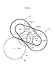
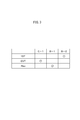
- the schematic side view of this automatic transmission The engagement table of this automatic transmission.
- the automatic transmission 1 is connected to an unillustrated engine (drive source) via a fluid transmission device such as a torque converter with a lock-up clutch, or a starting device such as a starting clutch.
- the input shaft 10 to be connected is provided on the first shaft AX1.
- the input shaft 10 is on the first shaft AX1 coaxial with the input shaft 10.
- the planetary gear set PS and the belt-type continuously variable transmission mechanism are provided in the case 11. 20 (hereinafter referred to as “CVT20”) primary pulleys 21 are arranged.
- a secondary pulley 22 of the CVT 20 is disposed on a second axis AX2 parallel to the first axis AX1, and the secondary pulley 22 and the counter shaft 40 are connected to each other.
- a clutch C-1 to which rotation transmission can be freely connected is arranged.
- a second output gear (a forward / reverse output gear) 31 of a planetary gear set PS, which will be described in detail later, and a second output gear connected to the clutch C-1 ( A countershaft 40 that meshes with the continuously variable transmission output gear) 27 is disposed, and a differential device 60 that meshes with the countershaft 40 is disposed on a fourth axis AX4 parallel to the first axis AX1.
- the output shafts (ask shafts) 62r and 62l that are drivingly connected to a wheel (not shown) are arranged on the fourth axis AX4 from substantially the center.
- the large-diameter gear (driven gear) 42 of the countershaft 40 on the third axis AX3 is the first output gear 31 of the planetary gear set PS on the first axis AX1 and the second output gear on the second axis AX2. 27, and the small-diameter gear 43 of the countershaft 40 on the third axis AX3 meshes with the diff ring gear 61 of the differential device 60 on the fourth axis AX4.
- a planetary gear set PS which will be described in detail later, is disposed on the outer peripheral side of the input shaft 10 on the first axis AX1 on the axial input side.
- a fixed sheave 21a of the primary pulley 21 of the CVT 20 is drivably coupled to the input shaft 10 on the side opposite to the planetary gear set PS in the axial direction of the input shaft 10 on the first shaft AX1.
- the primary pulley 21 has a fixed sheave 21a and a movable sheave 21b that is movable in the axial direction with respect to the fixed sheave 21a.
- a secondary pulley 22 of the CVT 20 is disposed on the second axis AX2 so as to face the primary pulley 21. Similar to the primary pulley 21, the secondary pulley 22 has a fixed sheave 22a and a movable sheave 22b that is movable in the axial direction with respect to the fixed sheave 22a, and is disposed on the back surface of the movable sheave 22b.
- the belt 23 is sandwiched between the fixed sheave 22a and the movable sheave 22b by the oil pressure of the oil chamber.
- a first drive shaft 25 centered on the second shaft AX2 is fixedly connected to the fixed sheave 22a of the secondary pulley 22 on the second shaft AX2, and the end of the first drive shaft 25 is fixed.
- the clutch C-1 is disposed coaxially with the secondary pulley 22, that is, on the second axis AX2. Further, on the output side of the clutch C-1, a second drive shaft 26 centered on the second shaft AX2 is drivingly connected and fixed to the clutch C-1 of the second drive shaft 26 in the axial direction. On the opposite side (that is, the input side), the second output gear 27 is connected to the second drive shaft 26 and fixed. That is, the clutch C-1 is arranged so that the secondary pulley 22 and the second output gear 27 can be connected, and is a clutch that can connect a first transmission path CO1 described later in detail.
- the CVT 20 including the primary pulley 21 and the secondary pulley 22 has a speed ratio width set in a range where the speed ratio is smaller than the forward low speed stage of the planetary gear set PS, that is, the speed ratio is increased. Therefore, it is not necessary to increase the diameter of each sheave 21a, 21b, 22a, 22b, so that the CVT 20 can be reduced in diameter.
- the contact radius of the belt 23 is small on the primary pulley 21 side and large on the secondary pulley 22 side.
- the side with the large gear ratio is the “Lo” side
- the contact radius of the belt 23 is the primary pulley.
- the “Hi” side is the side with the smaller gear ratio, which is larger on the 21 side and smaller on the secondary pulley 22 side.
- the counter shaft 40 is disposed on the third axis AX3.
- the counter shaft 40 includes a central shaft 41, a large diameter gear 42 fixed to one end portion of the central shaft 41, and a small diameter gear 43 fixed to the other end portion of the central shaft 41. Yes.
- the large-diameter gear 42 meshes with a first output gear 31 that is drivingly connected to a planetary gear set PS, which will be described later, and a second output gear 27 that is drivingly connected to the secondary pulley 22 via a clutch C-1.
- the small-diameter gear 43 meshes with the diff ring gear 61 of the differential device 60 and absorbs the rotation input to the counter shaft 40 to the left and right output shafts 62r and 62l via the differential portion D. Rotate output.
- the single-pinion type planetary gear on the inner peripheral side and the single-pinion type planetary gear on the outer peripheral side are combined in a two-story structure, and the first sun gear S1 and the first ring gear on the inner peripheral side are combined.
- the first sun gear S1 is drivingly connected to the input shaft 10, and the input rotation from the engine is always inputted.
- the intermediate gear MG is connected to the second brake B-2 disposed on the primary pulley 21 side with respect to the planetary gear set PS in the axial direction, and is rotated with respect to the case 11 by the second brake B-2. Is freely lockable.
- the second ring gear R2 is connected to the first brake B-1 disposed on the outer peripheral side of the planetary gear set PS, and the first brake B-1 can freely lock the rotation with respect to the case 11. It has become.
- the common carrier CR is drivably coupled to the first output gear 31 disposed on the opposite side in the axial direction from the second brake B-2 and the primary pulley 21 with respect to the planetary gear set PS.
- the differential shaft 60 from the counter shaft 40 passes through the CVT 20, the clutch C- 1 and the second output gear 27 from the input shaft 10.
- the first transmission path CO1 for transmitting power by continuously variable transmission is formed up to the left and right output shafts 62r and 62l.
- the planetary gear (not passing through the CVT 20) is connected in parallel with the CVT 20 from the input shaft 10 through the planetary gear set PS and the first output gear 31 to the left and right output shafts 62r and 62l through the differential device 60.
- a second transmission path CO2 for transmitting power by the set PS is formed.
- the automatic transmission 1 for example, when the reverse range (R range) is selected and a reverse speed (Rev) is achieved by a command from a control unit (not shown), as shown in FIG. B-1 is engaged, and the second brake B-2 and clutch C-1 are released. Then, as shown in FIGS. 1 and 4, the rotation of the second ring gear R2 in the planetary gear set PS is fixed, the rotation input from the input shaft 10 is input to the first sun gear S1, and the reverse rotation is performed from the common carrier CR. Is output. Thereby, as shown in FIG. 1, in the second transmission path CO2, the first output gear 31 rotates in the reverse direction on the first axis AX1, and the counter shaft on the third axis AX3 meshes with the first output gear 31.
- the automatic transmission 1 for example, when the drive range (D range) is selected and the first speed (1st) as the forward low speed is achieved by a command from a control unit (not shown) based on the vehicle speed.
- the second brake B-2 is engaged, and the first brake B-1 and the clutch C-1 are released.
- the rotation of the first ring gear R1 in the planetary gear set PS is fixed, the rotation input from the input shaft 10 is input to the first sun gear S1, and the decelerated rotation is performed from the common carrier CR. Is output.
- the first output gear 31 is decelerated and rotated in the forward rotation direction on the first shaft AX1, and is engaged with the first output gear 31.
- the upper counter shaft 40 rotates in the reverse direction, and the differential portion D on the fourth axis AX4 and the output shafts 62r and 62l meshing with the counter shaft 40 rotate in the normal direction. Forward rotation is output.
- the rotation input from the first sun gear S1 is transmitted to the first pinion P1 using the first ring gear R1 to which the rotation is fixed as a reaction force. Therefore, there are only two meshing locations, the first sun gear S1 and the first pinion P1, and the first ring gear R1 and the first pinion P1, for example, a Ravigneaux type planetary gear set described in Japanese Patent Application Laid-Open No. 2014-196772.
- the number of meshing portions is smaller than in the case of, and the transmission efficiency is good.
- the vehicle speed increases to a predetermined vehicle speed or more, and a continuously variable transmission mode (CVT mode) is received by a command from a control unit (not shown).
- CVT mode continuously variable transmission mode
- the axial positions of the movable sheave 21b of the primary pulley 21 and the movable sheave 22b of the secondary pulley 22 are hydraulically controlled in the first transmission path CO1, and the contact radius of the belt 23 is, for example, It is freely changed according to the vehicle speed and the accelerator opening, and the speed ratio width Va from the maximum speed ratio Lo of the CVT 20 (for example, set to a speed ratio of about the second speed speed in a multi-speed transmission) to the minimum speed ratio Hi.
- the rotation of the input shaft 10 is changed. As a result, as shown in FIG.
- the second output gear 27 is continuously variablely rotated in the forward rotation direction on the second shaft AX2 via the first drive shaft 25, the clutch C-1, and the second drive shaft 26.
- the counter shaft 40 on the third axis AX3 meshing with the second output gear 27 rotates continuously in the reverse direction, and the differential portion D on the fourth axis AX4 meshing with the counter shaft 40 and the output shaft 62r, 621 continuously rotates in the forward direction, that is, continuously variable speed rotation based on the gear ratio width Va is output to a wheel (not shown).
- the automatic transmission (1) includes a primary pulley (21) and a secondary pulley (22), and a belt (23) wound around these pulleys, and an input shaft (10).
- a continuously variable transmission mechanism (20) that forms a first transmission path (CO1) that can continuously rotate the rotation input to the output shaft and output it to the output shaft (62l, 62r);
- a clutch (C-1) connectable to the first transmission path (CO1);
- a second transmission path (CO2) from the input shaft (10) to the output shaft (621, 62r) is formed in parallel with the continuously variable transmission mechanism (20), and a forward gear and a reverse gear are achieved.
- the planetary gear set includes a first sun gear (S1), an integral intermediate gear (MG) in which a first ring gear (R1) is formed on the inner peripheral side and a second sun gear (S2) is formed on the outer peripheral side.
- a common carrier that meshes and rotatably supports a second pinion (P2) that is disposed so as to at least partially overlap the first pinion (P1) in the axial direction when viewed from the radial direction. It consists of a two-story planetary gear set (PS).
- the automatic transmission 1 forms a second transmission path CO2 from the input shaft 10 to the output shafts 62r and 62l in parallel with the CVT 20, and the first speed stage (1st) as the forward speed and the reverse speed (Rev) and the planetary gear set PS that can change the rotation input to the input shaft 10 by the forward gear or the reverse gear and output it to the output shafts 62r and 62l. Therefore, the CVT 20 is not used.
- the first forward speed (1st) can be achieved, and in particular, by increasing the gear ratio of the first speed stage, it is not necessary to transmit a large torque in the CVT 20, and the high belt 23 Accordingly, the load on the oil pump (not shown) can be reduced, and the transmission efficiency of the automatic transmission 1 can be improved.
- the gear ratio width Va in the CVT 20 can be set within a small gear ratio range (so-called upshift side), and large torque is transmitted in the CVT 20. Therefore, it is possible to reduce the load on the belt 23 and the load on the shaft support structure of each sheave 21a, 21b, 22a, 22b in the primary pulley 21 and the secondary pulley 22, and the CVT 20 can be reduced in size. And cost reduction can be achieved.
- the planetary gear set PS that can achieve the forward gear and the reverse gear without using the CVT 20 is constituted by a two-story planetary gear set, the load of the oil pump can be reduced and the fuel efficiency can be improved.
- the axial direction of the automatic transmission 1 can be shortened, and vehicle mountability can be improved.
- the two-story planetary gear set (PS) and the primary pulley (21) are disposed on a first shaft (AX1) coaxial with the input shaft (10),
- the secondary pulley (22) is disposed on a second axis (AX2) parallel to the first axis (AX1),
- a fourth axis parallel to the first axis (AX1) is arranged on a third axis (AX3) parallel to the first axis (AX1), and reverses and decelerates rotation from the two-story planetary gear set (PS).
- a forward / reverse output gear (31) that is drivingly connected to a common carrier (CR) of the two-story planetary gear set (PS) and meshes with a driven gear (42) of the counter shaft (40).
- the automatic transmission 1 can be configured with four shafts. Further, in the forward gear, in the two-story planetary gear set PS, the meshing locations can be only two locations of the first sun gear S1 and the first pinion P1, the first ring gear R1 and the first pinion P1, and transmission efficiency can be improved. Can be good.
- the automatic transmission (1) is on the first shaft (AX1), and the second brake (B-2) is axially connected to the primary pulley with respect to the two-story planetary gear set (PS). (21) side, and the forward / reverse output gear (31) is disposed on the opposite side to the second brake (B-2) in the axial direction with respect to the two-story planetary gear set (PS).
- the second brake B-2 when the second brake B-2 is disposed on the engine side in the axial direction and the first output gear 31 is disposed on the primary pulley 21 side in the axial direction with respect to the planetary gear set PS (that is, the first output in FIG. 1).
- the large diameter of the countershaft 40 is obtained because the second output gear 27 is disposed on the engine side in the axial direction from the clutch C-1.
- the gear 42 is also on the engine side in the axial direction with respect to the clutch C-1, and the first output gear 31 meshing with the large-diameter gear 42 is also on the engine side in the axial direction with respect to the clutch C-1. Shortening is impeded.
- the second brake B-2 and the first output gear 31 are axially viewed in the clutch C-1 from the radial direction. It is possible to arrange them so as to overlap each other, and it is not necessary to create a useless space particularly in the first axis AX1, and the axial direction can be shortened.
- the automatic transmission (1) includes a continuously variable transmission output gear (27) that is on the second shaft (AX2) and meshes with the driven gear (42) of the countershaft (40).
- the clutch (C-1) is disposed on the second shaft (AX2) so as to be able to connect rotation transmission between the secondary pulley (22) and the continuously variable transmission output gear (27).
- the clutch C-1 can be arranged as a clutch that can connect the first transmission path CO1 as long as it is between the first sun gear S1 and the primary pulley 21 of the planetary gear set PS. Since the planetary gear set PS and the second brake B-2 are arranged on the first axis AX1, if the clutch C-1 is further arranged, shortening in the axial direction is prevented. However, as shown in FIG. 1, it is arranged between the secondary pulley 22 and the second output gear 27 so that the clutch C-1 is seen from the radial direction with respect to the planetary gear set PS and the second brake B-2. It is possible to arrange them so as to overlap in the direction, and it is not necessary to make a useless space especially in the second axis AX2, and the axial direction can be shortened.
- the configuration of the automatic transmission 1 connected to the engine has been described.
- the motor / generator is disposed on any one of the first to fourth axes, or
- the automatic transmission 1 may be configured as a hybrid drive device by being arranged on another shaft and connected to drive.
- the CVT 20 can be reduced in size by providing a gear ratio interval between the first speed (1st) of the planetary gear set PS and the maximum gear ratio Lo of the CVT 20.
- the first gear (1st) by the planetary gear set PS and the maximum gear ratio Lo of the CVT 20 are configured to have the same gear ratio by allowing a slight increase in size, so that there is no gear shift shock. It may be possible to enable transition from a step to a continuously variable transmission mode.
- the present automatic transmission can be used for an automatic transmission mounted on a vehicle such as a passenger car or a truck, and is particularly suitable for an apparatus that requires shortening in the axial direction.
Landscapes
- Engineering & Computer Science (AREA)
- General Engineering & Computer Science (AREA)
- Mechanical Engineering (AREA)
- Transmission Devices (AREA)
- Structure Of Transmissions (AREA)
Abstract
自動変速機(1)は、入力軸(10)に入力された回転を無段変速して出力軸(62l,62r)に出力し得る第1伝達経路(CO1)を形成する無段変速機構(20)と、第1伝達経路(CO1)を接続可能なクラッチ(C-1)と、無段変速機構(20)と並列的に入力軸(10)から出力軸(62l,62r)までの第2伝達経路(CO2)を形成し、かつ前進段と後進段とを達成し得るプラネタリギヤセット(PS)とを備える。このプラネタリギヤセット(PS)を、第1サンギヤ(S1)と、第1リングギヤ(R1)及び第2サンギヤ(S2)が一体の中間ギヤ(MG)と、第2リングギヤ(R2)と、第1ピニオン(P1)と第2ピニオン(P2)とを回転自在に支持する共通キャリヤ(CR)と、を有する二階建てプラネタリギヤセットで構成する。
Description
この技術は、車両等に搭載される自動変速機に係り、特に入力軸から無段変速機構を介して出力軸までの第1伝達経路と、該無段変速機構と並列的な入力軸から出力軸までの第2伝達経路とを形成する自動変速機に関する。
近年、車両等に搭載される自動変速機にあって、ベルト式無段変速装置を用いたものが種々提案されている。ベルト式無段変速装置は、特に変速比が大きい低速領域にあって駆動源のトルクが増幅されるため、ベルトの挟持圧を大きくしてベルトのスリップを防止する必要があり、オイルポンプを大型化して挟持圧を担保することになるので、オイルポンプによる駆動損失が大きくなり、車両の燃費向上の妨げになっている。
そこで、低速領域にあってベルト式無段変速装置を用いず、プラネタリギヤセットによって低速段及び後進段を達成することで、オイルポンプにおける駆動損失を少なくし、車両の燃費向上を図ったものが提案されている(特許文献1参照)。
ところで、上記特許文献1の自動変速機におけるプラネタリギヤセットには、低速段及び後進段を達成するため、2つのプラネタリギヤを軸方向に並べて連結した、いわゆるラビニヨ型のプラネタリギヤセットを用いている。しかしながら、ラビニヨ型のプラネタリギヤセットのように、軸方向に2つのプラネタリギヤを並べるものは、軸方向に対して自動変速機が長くなり、特にFF(フロントエンジン・フロントドライブ)タイプの車両のように、エンジンの出力軸(クランク軸)が車両進行方向の横向きに搭載される車両に対して、自動変速機を搭載する場合には、車両搭載性の観点から好ましくないという問題がある。
そこで、無段変速装置を用いずに前進段及び後進段を達成するプラネタリギヤセットを有し、かつ軸方向の短縮化を図ることが可能な自動変速機を提供することを目的とするものである。
本自動変速機は、
プライマリプーリ及びセカンダリプーリとそれらプーリに巻き掛けられたベルトとを有し、入力軸に入力された回転を無段変速して出力軸に出力し得る第1伝達経路を形成する無段変速機構と、
前記第1伝達経路を接続可能なクラッチと、
前記無段変速機構と並列的に前記入力軸から前記出力軸までの第2伝達経路を形成し、かつ前進段と後進段とを達成し得ると共に、前記入力軸に入力された回転を前記前進段又は前記後進段により変速して前記出力軸に出力し得るプラネタリギヤセットと、を備え、
前記プラネタリギヤセットを、第1サンギヤと、内周側に第1リングギヤが形成されると共に外周側に第2サンギヤが形成されている一体の中間ギヤと、第2リングギヤと、前記第1サンギヤ及び前記第1リングギヤに噛合する第1ピニオンと前記第2サンギヤ及び前記第2リングギヤに噛合すると共に径方向から視て前記第1ピニオンに少なくとも一部が軸方向に重なるように配置された第2ピニオンとを回転自在に支持する共通キャリヤと、を有する二階建てプラネタリギヤセットで構成する。
プライマリプーリ及びセカンダリプーリとそれらプーリに巻き掛けられたベルトとを有し、入力軸に入力された回転を無段変速して出力軸に出力し得る第1伝達経路を形成する無段変速機構と、
前記第1伝達経路を接続可能なクラッチと、
前記無段変速機構と並列的に前記入力軸から前記出力軸までの第2伝達経路を形成し、かつ前進段と後進段とを達成し得ると共に、前記入力軸に入力された回転を前記前進段又は前記後進段により変速して前記出力軸に出力し得るプラネタリギヤセットと、を備え、
前記プラネタリギヤセットを、第1サンギヤと、内周側に第1リングギヤが形成されると共に外周側に第2サンギヤが形成されている一体の中間ギヤと、第2リングギヤと、前記第1サンギヤ及び前記第1リングギヤに噛合する第1ピニオンと前記第2サンギヤ及び前記第2リングギヤに噛合すると共に径方向から視て前記第1ピニオンに少なくとも一部が軸方向に重なるように配置された第2ピニオンとを回転自在に支持する共通キャリヤと、を有する二階建てプラネタリギヤセットで構成する。
これにより、無段変速装置を用いずに前進段及び後進段を達成し得るプラネタリギヤセットを二階建てプラネタリギヤセットで構成したので、オイルポンプの負荷を低減して燃費の向上を図ることができるものでありながら、自動変速機の軸方向の短縮化を図ることができ、車両搭載性を向上することができる。
以下、本実施の形態を図1乃至図4に沿って説明する。
まず、本実施の形態に係る自動変速機1の概略構造について、図1及び図2に沿って説明する。自動変速機1は、図1及び図2に示すように、不図示のエンジン(駆動源)に、例えばロックアップクラッチ付のトルクコンバータ等の流体伝動装置、或いは発進クラッチなどの発進装置を介して接続される入力軸10を第1軸AX1上に備えており、その入力軸10と同軸の第1軸AX1上にあって、ケース11内に、プラネタリギヤセットPSと、ベルト式の無段変速機構20(以下、「CVT20」という)のプライマリプーリ21とが配置されている。
また、図1及び図2に示すように、第1軸AX1と平行な第2軸AX2上には、CVT20のセカンダリプーリ22が配置されていると共に、該セカンダリプーリ22と上記カウンタシャフト40との回転伝達を接続自在なクラッチC-1が配置されている。さらに、第1軸AX1と平行な第3軸AX3上には、詳しくは後述するプラネタリギヤセットPSの第1出力ギヤ(前後進出力ギヤ)31及びクラッチC-1に接続される第2出力ギヤ(無段変速出力ギヤ)27に噛合するカウンタシャフト40が配置されており、第1軸AX1と平行な第4軸AX4上に、カウンタシャフト40に噛合するディファレンシャル装置60が配置され、該ディファレンシャル装置60の略々中心から第4軸AX4上に不図示の車輪に駆動連結された出力軸(アスクルシャフト)62r,62lが配置されている。
即ち、第3軸AX3上にあるカウンタシャフト40の大径ギヤ(ドリブンギヤ)42は、第1軸AX1上にあるプラネタリギヤセットPSの第1出力ギヤ31及び第2軸AX2上にある第2出力ギヤ27に噛合していると共に、第3軸AX3上にあるカウンタシャフト40の小径ギヤ43は、第4軸AX4上にあるディファレンシャル装置60のデフリングギヤ61に噛合している。
続いて、自動変速機1の詳細構成について図1に沿って説明する。上記第1軸AX1上にある入力軸10の軸方向入力側の外周側には、詳しくは後述するプラネタリギヤセットPSが配置されている。上記第1軸AX1上にある入力軸10の軸方向におけるプラネタリギヤセットPSとは反対側には、CVT20のプライマリプーリ21の固定シーブ21aが該入力軸10に駆動連結されて固定されている。プライマリプーリ21は、固定シーブ21aと、該固定シーブ21aに対して軸方向に可動自在な可動シーブ21bとを有しており、可動シーブ21bの背面に配置された作動油室の油圧によって、それら固定シーブ21aと可動シーブ21bとの間にベルト23を挟持している。
また、上記第2軸AX2上には、上記プライマリプーリ21と対向する形で、CVT20のセカンダリプーリ22が配置されている。セカンダリプーリ22は、プライマリプーリ21と同様に、固定シーブ22aと、該固定シーブ22aに対して軸方向に可動自在な可動シーブ22bとを有しており、可動シーブ22bの背面に配置された作動油室の油圧によって、それら固定シーブ22aと可動シーブ22bとの間にベルト23を挟持している。
上記第2軸AX2上にあるセカンダリプーリ22の固定シーブ22aには、該第2軸AX2を中心とした第1駆動軸25が駆動連結されて固定されており、該第1駆動軸25の端部には、クラッチC-1が該セカンダリプーリ22と同軸上、つまり第2軸AX2上に配置されている。さらに、クラッチC-1の出力側には、該第2軸AX2を中心とした第2駆動軸26が駆動連結されて固定されており、第2駆動軸26のクラッチC-1とは軸方向反対側(つまり入力側)には、第2出力ギヤ27が第2駆動軸26に駆動連結されて固定されている。即ち、クラッチC-1は、セカンダリプーリ22と第2出力ギヤ27とを接続自在に配置されており、詳しくは後述する第1伝達経路CO1を接続可能なクラッチとなっている。
上記プライマリプーリ21及びセカンダリプーリ22からなるCVT20は、詳しくは後述するように、変速比幅が上記プラネタリギヤセットPSの前進低速段よりも変速比が小さい範囲で設定されており、つまり変速比を大きくなるように設定する必要がなく、各シーブ21a,21b,22a,22bの径を大径化しなくていいので、CVT20を小径化することが可能となっている。なお、図2に示すように、ベルト23の接触半径がプライマリプーリ21側で小さく、セカンダリプーリ22側で大きくなる、変速比が大きい側が「Lo」側であり、ベルト23の接触半径がプライマリプーリ21側で大きく、セカンダリプーリ22側で小さいくなる、変速比が小さい側が「Hi」側である。
上記第3軸AX3上にあっては、カウンタシャフト40が配置されている。カウンタシャフト40は、中心軸41と、その中心軸41の一端部に固定された大径ギヤ42と、その中心軸41の他端部に固定された小径ギヤ43とを有して構成されている。上記大径ギヤ42は、後述するプラネタリギヤセットPSに駆動連結された第1出力ギヤ31と、クラッチC-1を介してセカンダリプーリ22に駆動連結される第2出力ギヤ27とに噛合している。そして、小径ギヤ43は、ディファレンシャル装置60のデフリングギヤ61に噛合しており、カウンタシャフト40に入力された回転を、ディファレンシャル部Dを介して左右の出力軸62r,62lに差回転を吸収しつつ回転出力する。
そして、プラネタリギヤセットPSは、内周側のシングルピニオンタイプのプラネタリギヤと外周側のシングルピニオンタイプのプラネタリギヤとが2階建て構造として組合せられており、第1サンギヤS1と、内周側に第1リングギヤR1が形成されると共に外周側に第2サンギヤS2が形成されている一体の中間ギヤMGと、第2リングギヤR2と、第1サンギヤS1及び第1リングギヤR1に噛合する第1ピニオンP1と第2サンギヤS2及び第2リングギヤR2に噛合すると共に径方向から視て第1ピニオンP1に少なくとも一部が軸方向に重なるように配置される第2ピニオンP2とを回転自在に支持する共通キャリヤCRと、を有して構成されている。
このうち第1サンギヤS1は、入力軸10に駆動連結されており、エンジンからの入力回転が常時入力されている。また、中間ギヤMGは、軸方向においてプラネタリギヤセットPSよりもプライマリプーリ21側に配置されている第2ブレーキB-2に接続されており、該第2ブレーキB-2によってケース11に対して回転が係止自在となっている。さらに、第2リングギヤR2は、プラネタリギヤセットPSの外周側に配置されている第1ブレーキB-1に接続されており、該第1ブレーキB-1によってケース11に対して回転が係止自在となっている。そして、共通キャリヤCRは、プラネタリギヤセットPSに対して上記第2ブレーキB-2及びプライマリプーリ21とは軸方向反対側に配置された第1出力ギヤ31に駆動連結されている。
以上のように構成された自動変速機1にあっては、図1に示すように、入力軸10からCVT20、クラッチC-1、第2出力ギヤ27を通って、カウンタシャフト40からディファレンシャル装置60を介して左右の出力軸62r,62lまで、無段変速により動力伝達を行う第1伝達経路CO1を形成することになる。また、入力軸10からプラネタリギヤセットPS、第1出力ギヤ31を通って、カウンタシャフト40からディファレンシャル装置60を介して左右の出力軸62r,62lまで、CVT20と並列的に(CVT20を通らない)プラネタリギヤセットPSにより動力伝達を行う第2伝達経路CO2を形成することになる。
ついで、本実施の形態に係る自動変速機1の動作について、図1を参照しつつ図3及び図4に沿って説明する。
まず、自動変速機1において、例えばリバースレンジ(Rレンジ)が選択されて不図示の制御部からの指令で、後進段(Rev)を達成する際は、図3に示すように、第1ブレーキB-1を係合し、第2ブレーキB-2及びクラッチC-1を解放する。すると、図1及び図4に示すように、プラネタリギヤセットPSにおける第2リングギヤR2の回転が固定され、入力軸10から入力された回転が第1サンギヤS1に入力され、共通キャリヤCRからは逆転回転が出力される。これにより、図1に示すように、第2伝達経路CO2において、第1出力ギヤ31が第1軸AX1上で逆転回転し、該第1出力ギヤ31に噛合する第3軸AX3上のカウンタシャフト40が正転回転し、該カウンタシャフト40に噛合する第4軸AX4上のディファレンシャル部D及び出力軸62r,62lが逆転回転し、つまり不図示の車輪に後進段としての逆転回転が出力される。
次に、自動変速機1において、例えばドライブレンジ(Dレンジ)が選択されて車速に基づき不図示の制御部からの指令で、前進低速段としての第1速段(1st)を達成する際は、図3に示すように、第2ブレーキB-2を係合し、第1ブレーキB-1及びクラッチC-1を解放する。すると、図1及び図4に示すように、プラネタリギヤセットPSにおける第1リングギヤR1の回転が固定され、入力軸10から入力された回転が第1サンギヤS1に入力され、共通キャリヤCRから減速回転が出力される。これにより、図1に示すように、第2伝達経路CO2において、第1出力ギヤ31が第1軸AX1上で正転方向に減速回転し、該第1出力ギヤ31に噛合する第3軸AX3上のカウンタシャフト40が逆転回転し、該カウンタシャフト40に噛合する第4軸AX4上のディファレンシャル部D及び出力軸62r,62lが正転回転し、つまり不図示の車輪に第1速段としての正転回転が出力される。
なお、この第1速段の状態にあって、プラネタリギヤセットPSでは、第1サンギヤS1から入力された回転が、回転が固定された第1リングギヤR1を反力として第1ピニオンP1に伝達されるので、噛み合い箇所が第1サンギヤS1及び第1ピニオンP1と、第1リングギヤR1及び第1ピニオンP1との2箇所だけであり、例えば特開2014-196772号公報に記載されたラビニヨ型のプラネタリギヤセットの場合よりも噛み合い箇所が少なくなり、伝達効率が良好である。
続いて、自動変速機1において、例えばドライブレンジ(Dレンジ)が選択されている状態で車速が所定車速以上に上昇し、不図示の制御部からの指令で、無段変速モード(CVTモード)を達成する際は、図3に示すように、第2ブレーキB-2を解放しつつクラッチC-1を係合し(例えば掴み換え変速し)、第1ブレーキB-1及び第2ブレーキB-2を解放状態にする。すると、図4に示すように、第1伝達経路CO1において、CVT20のプライマリプーリ21の可動シーブ21b及びセカンダリプーリ22の可動シーブ22bの軸方向位置が油圧制御されて、ベルト23の接触半径が例えば車速やアクセル開度に応じて自在に変更され、CVT20の最大変速比Lo(例えば多段変速機における第2速段程度の変速比に設定される)から最小変速比Hiまでの変速比幅Vaで入力軸10の回転を変速する。これにより、図1に示すように、第1駆動軸25、クラッチC-1、第2駆動軸26を介して第2出力ギヤ27が第2軸AX2上で正転方向に無段変速回転し、該第2出力ギヤ27に噛合する第3軸AX3上のカウンタシャフト40が逆転方向に無段変速回転し、該カウンタシャフト40に噛合する第4軸AX4上のディファレンシャル部D及び出力軸62r,62lが正転方向に無段変速回転し、つまり不図示の車輪に変速比幅Vaに基づく無段変速回転が出力される。
<本実施の形態のまとめ>
以上説明した本実施の形態に係る自動変速機(1)は、プライマリプーリ(21)及びセカンダリプーリ(22)とそれらプーリに巻き掛けられたベルト(23)とを有し、入力軸(10)に入力された回転を無段変速して出力軸(62l,62r)に出力し得る第1伝達経路(CO1)を形成する無段変速機構(20)と、
前記第1伝達経路(CO1)を接続可能なクラッチ(C-1)と、
前記無段変速機構(20)と並列的に前記入力軸(10)から前記出力軸(62l,62r)までの第2伝達経路(CO2)を形成し、かつ前進段と後進段とを達成し得ると共に、前記入力軸(10)に入力された回転を前記前進段又は前記後進段により変速して前記出力軸(62l,62r)に出力し得るプラネタリギヤセット(PS)と、を備え、
前記プラネタリギヤセットを、第1サンギヤ(S1)と、内周側に第1リングギヤ(R1)が形成されると共に外周側に第2サンギヤ(S2)が形成されている一体の中間ギヤ(MG)と、第2リングギヤ(R2)と、前記第1サンギヤ(S1)及び前記第1リングギヤ(R1)に噛合する第1ピニオン(P1)と前記第2サンギヤ(S2)及び前記第2リングギヤ(R2)に噛合すると共に径方向から視て前記第1ピニオン(P1)に少なくとも一部が軸方向に重なるように配置された第2ピニオン(P2)とを回転自在に支持する共通キャリヤ(CR)と、を有する二階建てプラネタリギヤセット(PS)で構成する。
以上説明した本実施の形態に係る自動変速機(1)は、プライマリプーリ(21)及びセカンダリプーリ(22)とそれらプーリに巻き掛けられたベルト(23)とを有し、入力軸(10)に入力された回転を無段変速して出力軸(62l,62r)に出力し得る第1伝達経路(CO1)を形成する無段変速機構(20)と、
前記第1伝達経路(CO1)を接続可能なクラッチ(C-1)と、
前記無段変速機構(20)と並列的に前記入力軸(10)から前記出力軸(62l,62r)までの第2伝達経路(CO2)を形成し、かつ前進段と後進段とを達成し得ると共に、前記入力軸(10)に入力された回転を前記前進段又は前記後進段により変速して前記出力軸(62l,62r)に出力し得るプラネタリギヤセット(PS)と、を備え、
前記プラネタリギヤセットを、第1サンギヤ(S1)と、内周側に第1リングギヤ(R1)が形成されると共に外周側に第2サンギヤ(S2)が形成されている一体の中間ギヤ(MG)と、第2リングギヤ(R2)と、前記第1サンギヤ(S1)及び前記第1リングギヤ(R1)に噛合する第1ピニオン(P1)と前記第2サンギヤ(S2)及び前記第2リングギヤ(R2)に噛合すると共に径方向から視て前記第1ピニオン(P1)に少なくとも一部が軸方向に重なるように配置された第2ピニオン(P2)とを回転自在に支持する共通キャリヤ(CR)と、を有する二階建てプラネタリギヤセット(PS)で構成する。
これにより、本自動変速機1は、CVT20と並列的に入力軸10から出力軸62r,62lまでの第2伝達経路CO2を形成し、かつ前進段としての第1速段(1st)と後進段(Rev)とを達成し得ると共に、入力軸10に入力された回転を前進段又は後進段により変速して出力軸62r,62lに出力し得るプラネタリギヤセットPSを備えているので、CVT20を用いずに前進の第1速段(1st)を達成することができ、特に第1速段の変速比を大きくすることで、CVT20において大きなトルクを伝達することを不要とすることができ、高いベルト23の挟持圧も不要となって不図示のオイルポンプの負荷を低減することができ、自動変速機1としての伝達効率を向上することができる。
また、特に第1速段の変速比を大きくすることで、CVT20における変速比幅Vaを変速比の小さい範囲(いわゆるアップシフト側)に設定することが可能となって、CVT20において大きなトルクを伝達することを不要とすることができるので、ベルト23の負荷や、プライマリプーリ21及びセカンダリプーリ22における各シーブ21a,21b,22a,22bの軸支持構造の負荷を低減することができ、CVT20の小型化や低コスト化を図ることができる。
そして、CVT20を用いずに前進段及び後進段を達成し得るプラネタリギヤセットPSを二階建てプラネタリギヤセットで構成したので、オイルポンプの負荷を低減して燃費の向上を図ることができるものでありながら、自動変速機1の軸方向の短縮化を図ることができ、車両搭載性を向上することができる。
また、本自動変速機(1)は、前記二階建てプラネタリギヤセット(PS)及び前記プライマリプーリ(21)は、前記入力軸(10)と同軸の第1軸(AX1)上に配置され、
前記セカンダリプーリ(22)は、前記第1軸(AX1)と平行な第2軸(AX2)上に配置され、
前記第1軸(AX1)と平行な第3軸(AX3)上に配置され、該二階建てプラネタリギヤセット(PS)からの回転を反転減速して、前記第1軸(AX1)と平行な第4軸(AX4)上に配置された前記出力軸(62l,62r)に出力するカウンタシャフト(40)と、
前記第2リングギヤの回転をケース(11)に対して係止自在な第1ブレーキ(B-1)と、
前記中間ギヤ(MG)の回転をケース(11)に対して係止自在な第2ブレーキ(B-2)と、
前記二階建てプラネタリギヤセット(PS)の共通キャリヤ(CR)に駆動連結されると共に、前記カウンタシャフト(40)のドリブンギヤ(42)に噛合する前後進出力ギヤ(31)と、を備える。
前記セカンダリプーリ(22)は、前記第1軸(AX1)と平行な第2軸(AX2)上に配置され、
前記第1軸(AX1)と平行な第3軸(AX3)上に配置され、該二階建てプラネタリギヤセット(PS)からの回転を反転減速して、前記第1軸(AX1)と平行な第4軸(AX4)上に配置された前記出力軸(62l,62r)に出力するカウンタシャフト(40)と、
前記第2リングギヤの回転をケース(11)に対して係止自在な第1ブレーキ(B-1)と、
前記中間ギヤ(MG)の回転をケース(11)に対して係止自在な第2ブレーキ(B-2)と、
前記二階建てプラネタリギヤセット(PS)の共通キャリヤ(CR)に駆動連結されると共に、前記カウンタシャフト(40)のドリブンギヤ(42)に噛合する前後進出力ギヤ(31)と、を備える。
これにより、本自動変速機1を4つの軸により構成することができる。また、前進段では、二階建てプラネタリギヤセットPSのうち、噛み合い箇所を第1サンギヤS1及び第1ピニオンP1と第1リングギヤR1及び第1ピニオンP1との2箇所だけにすることができ、伝達効率を良好にすることができる。
また、本自動変速機(1)は、前記第1軸(AX1)上にあって、前記第2ブレーキ(B-2)が前記二階建てプラネタリギヤセット(PS)に対して軸方向の前記プライマリプーリ(21)側に配置され、前記前後進出力ギヤ(31)が前記二階建てプラネタリギヤセット(PS)に対して前記第2ブレーキ(B-2)とは軸方向反対側に配置される。
即ち、例えば第2ブレーキB-2を軸方向のエンジン側に、第1出力ギヤ31をプラネタリギヤセットPSに対して軸方向のプライマリプーリ21側に配置した場合には(つまり図1において第1出力ギヤ31と第2ブレーキB-2との位置を入れ替えた場合には)、第2出力ギヤ27がクラッチC-1よりも軸方向のエンジン側に配置される関係上、カウンタシャフト40の大径ギヤ42もクラッチC-1よりも軸方向のエンジン側となり、該大径ギヤ42に噛合する第1出力ギヤ31もクラッチC-1よりも軸方向のエンジン側となって、全体として軸方向の短縮化が妨げられる。
しかし、図1に示すように第2ブレーキB-2及び第1出力ギヤ31を配置することで、第2ブレーキB-2やプラネタリギヤセットPSをクラッチC-1に径方向から視て軸方向に重ねるように配置することが可能となって、特に第1軸AX1において無駄な空間を作る必要がなくなり、軸方向の短縮化を図ることができる。
そして、本自動変速機(1)は、前記第2軸(AX2)上にあって、前記カウンタシャフト(40)のドリブンギヤ(42)に噛合する無段変速出力ギヤ(27)を備え、
前記クラッチ(C-1)は、前記第2軸(AX2)上にあって、前記セカンダリプーリ(22)と前記無段変速出力ギヤ(27)との回転伝達を接続自在となるように配置される。
前記クラッチ(C-1)は、前記第2軸(AX2)上にあって、前記セカンダリプーリ(22)と前記無段変速出力ギヤ(27)との回転伝達を接続自在となるように配置される。
即ち、例えばクラッチC-1は、プラネタリギヤセットPSの第1サンギヤS1とプライマリプーリ21との間であれば第1伝達経路CO1を接続可能なクラッチとして配置することが可能であるが、その場合は、第1軸AX1上にプラネタリギヤセットPSや第2ブレーキB-2が配置されているため、クラッチC-1をさらに配置してしまうと軸方向の短縮化が妨げられる。しかし、図1に示すようにセカンダリプーリ22と第2出力ギヤ27との間に配置することで、プラネタリギヤセットPSや第2ブレーキB-2に対してクラッチC-1に径方向から視て軸方向に重ねるように配置することが可能となって、特に第2軸AX2において無駄な空間を作る必要がなくなり、軸方向の短縮化を図ることができる。
なお、以上説明した本実施の形態では、エンジンに接続する自動変速機1の構成について説明したが、例えばモータ・ジェネレータを第1軸~第4軸の何れかの軸上に配置したり、或いはさらに別の軸上に配置して駆動連結したりして、自動変速機1をハイブリッド駆動装置として構成するようにしてもよい。
また、以上説明した本実施の形態においては、プラネタリギヤセットPSによる第1速段(1st)と、CVT20の最大変速比Loとの間に、ギヤ比の間隔を設けることで、CVT20の小型化を図っているが、多少の大型化を許容して、プラネタリギヤセットPSによる第1速段(1st)とCVT20の最大変速比Loとを同一のギヤ比に構成することで、変速ショックの無い、前進段から無段変速モードへの移行を可能にできるようにしてもよい。
本自動変速機は、乗用車、トラック等の車両に搭載される自動変速機に用いることが可能であり、特に軸方向の短縮化が求められるものに用いて好適である。
1 自動変速機
10 入力軸
11 ケース
20 無段変速機構(CVT)
21 プライマリプーリ
22 セカンダリプーリ
23 ベルト
27 無段変速出力ギヤ(第2出力ギヤ)
31 前後進出力ギヤ(第1出力ギヤ)
40 カウンタシャフト
42 ドリブンギヤ(大径ギヤ)
62l,62r 出力軸
CO1 第1伝達経路
CO2 第2伝達経路
C-1 クラッチ
PS プラネタリギヤセット、二階建てプラネタリギヤセット
S1 第1サンギヤ
P1 第1ピニオン
R1 第1リングギヤ
S2 第2サンギヤ
P2 第2ピニオン
R2 第2リングギヤ
CR 共通キャリヤ
MG 中間ギヤ
AX1 第1軸
AX2 第2軸
AX3 第3軸
AX4 第4軸
B-1 第1ブレーキ
B-2 第2ブレーキ
10 入力軸
11 ケース
20 無段変速機構(CVT)
21 プライマリプーリ
22 セカンダリプーリ
23 ベルト
27 無段変速出力ギヤ(第2出力ギヤ)
31 前後進出力ギヤ(第1出力ギヤ)
40 カウンタシャフト
42 ドリブンギヤ(大径ギヤ)
62l,62r 出力軸
CO1 第1伝達経路
CO2 第2伝達経路
C-1 クラッチ
PS プラネタリギヤセット、二階建てプラネタリギヤセット
S1 第1サンギヤ
P1 第1ピニオン
R1 第1リングギヤ
S2 第2サンギヤ
P2 第2ピニオン
R2 第2リングギヤ
CR 共通キャリヤ
MG 中間ギヤ
AX1 第1軸
AX2 第2軸
AX3 第3軸
AX4 第4軸
B-1 第1ブレーキ
B-2 第2ブレーキ
Claims (4)
- プライマリプーリ及びセカンダリプーリとそれらプーリに巻き掛けられたベルトとを有し、入力軸に入力された回転を無段変速して出力軸に出力し得る第1伝達経路を形成する無段変速機構と、
前記第1伝達経路を接続可能なクラッチと、
前記無段変速機構と並列的に前記入力軸から前記出力軸までの第2伝達経路を形成し、かつ前進段と後進段とを達成し得ると共に、前記入力軸に入力された回転を前記前進段又は前記後進段により変速して前記出力軸に出力し得るプラネタリギヤセットと、を備え、
前記プラネタリギヤセットを、第1サンギヤと、内周側に第1リングギヤが形成されると共に外周側に第2サンギヤが形成されている一体の中間ギヤと、第2リングギヤと、前記第1サンギヤ及び前記第1リングギヤに噛合する第1ピニオンと前記第2サンギヤ及び前記第2リングギヤに噛合すると共に径方向から視て前記第1ピニオンに少なくとも一部が軸方向に重なるように配置された第2ピニオンとを回転自在に支持する共通キャリヤと、を有する二階建てプラネタリギヤセットで構成した、
自動変速機。 - 前記二階建てプラネタリギヤセット及び前記プライマリプーリは、前記入力軸と同軸の第1軸上に配置され、
前記セカンダリプーリは、前記第1軸と平行な第2軸上に配置され、
前記第1軸と平行な第3軸上に配置され、該二階建てプラネタリギヤセットからの回転を反転減速して、前記第1軸と平行な第4軸上に配置された前記出力軸に出力するカウンタシャフトと、
前記第2リングギヤの回転をケースに対して係止自在な第1ブレーキと、
前記中間ギヤの回転をケースに対して係止自在な第2ブレーキと、
前記二階建てプラネタリギヤセットの共通キャリヤに駆動連結されると共に、前記カウンタシャフトのドリブンギヤに噛合する前後進出力ギヤと、を備えた、
請求項1に記載の自動変速機。 - 前記第1軸上にあって、前記第2ブレーキが前記二階建てプラネタリギヤセットに対して軸方向の前記プライマリプーリ側に配置され、前記前後進出力ギヤが前記二階建てプラネタリギヤセットに対して前記第2ブレーキとは軸方向反対側に配置された、
請求項2に記載の自動変速機。 - 前記第2軸上にあって、前記カウンタシャフトのドリブンギヤに噛合する無段変速出力ギヤを備え、
前記クラッチは、前記第2軸上にあって、前記セカンダリプーリと前記無段変速出力ギヤとの回転伝達を接続自在となるように配置された、
請求項2または3に記載の自動変速機。
Applications Claiming Priority (2)
| Application Number | Priority Date | Filing Date | Title |
|---|---|---|---|
| JP2015028885A JP2016151315A (ja) | 2015-02-17 | 2015-02-17 | 自動変速機 |
| JP2015-028885 | 2015-02-17 |
Publications (1)
| Publication Number | Publication Date |
|---|---|
| WO2016132819A1 true WO2016132819A1 (ja) | 2016-08-25 |
Family
ID=56688763
Family Applications (1)
| Application Number | Title | Priority Date | Filing Date |
|---|---|---|---|
| PCT/JP2016/051940 Ceased WO2016132819A1 (ja) | 2015-02-17 | 2016-01-22 | 自動変速機 |
Country Status (2)
| Country | Link |
|---|---|
| JP (1) | JP2016151315A (ja) |
| WO (1) | WO2016132819A1 (ja) |
Citations (3)
| Publication number | Priority date | Publication date | Assignee | Title |
|---|---|---|---|---|
| JP2011080589A (ja) * | 2009-09-09 | 2011-04-21 | Honda Motor Co Ltd | 自動変速機 |
| JP2012202473A (ja) * | 2011-03-25 | 2012-10-22 | Jatco Ltd | 自動変速機 |
| JP2014196772A (ja) * | 2013-03-29 | 2014-10-16 | アイシン・エィ・ダブリュ株式会社 | 車両用駆動装置 |
-
2015
- 2015-02-17 JP JP2015028885A patent/JP2016151315A/ja active Pending
-
2016
- 2016-01-22 WO PCT/JP2016/051940 patent/WO2016132819A1/ja not_active Ceased
Patent Citations (3)
| Publication number | Priority date | Publication date | Assignee | Title |
|---|---|---|---|---|
| JP2011080589A (ja) * | 2009-09-09 | 2011-04-21 | Honda Motor Co Ltd | 自動変速機 |
| JP2012202473A (ja) * | 2011-03-25 | 2012-10-22 | Jatco Ltd | 自動変速機 |
| JP2014196772A (ja) * | 2013-03-29 | 2014-10-16 | アイシン・エィ・ダブリュ株式会社 | 車両用駆動装置 |
Also Published As
| Publication number | Publication date |
|---|---|
| JP2016151315A (ja) | 2016-08-22 |
Similar Documents
| Publication | Publication Date | Title |
|---|---|---|
| CN104334924B (zh) | 无级变速器 | |
| CN104364558B (zh) | 车辆用动力传递装置 | |
| US7553253B2 (en) | Automatic transmission | |
| US8512198B2 (en) | Automatic transmission | |
| CN104145133B (zh) | 自动变速机 | |
| JP2006132595A (ja) | 車両用自動変速機 | |
| KR20040104919A (ko) | 차량용 다단 자동 변속기 | |
| US10670122B2 (en) | Automatic transmission | |
| US11002340B2 (en) | Automatic transmission | |
| US20120244985A1 (en) | Automatic transmission | |
| US20170211672A1 (en) | Automatic transmission | |
| CN105793616A (zh) | Cvt驱动系 | |
| JP2008144904A (ja) | パワースプリット型無段変速装置 | |
| JP2006329338A (ja) | 分流式無段変速機 | |
| JP6358345B2 (ja) | 自動変速機 | |
| JP6094325B2 (ja) | 車両用駆動装置 | |
| JP2009036231A (ja) | 変速装置 | |
| JP2016151315A (ja) | 自動変速機 | |
| JP2015152076A (ja) | 無段変速機 | |
| JP6365246B2 (ja) | 自動変速機 | |
| JP2016164419A (ja) | 自動変速機 | |
| JP2016188690A (ja) | 自動変速機 | |
| US9541171B2 (en) | Automatic transmission for vehicles | |
| JP5790575B2 (ja) | 変速機 | |
| JP2017032036A (ja) | 自動変速機 |
Legal Events
| Date | Code | Title | Description |
|---|---|---|---|
| 121 | Ep: the epo has been informed by wipo that ep was designated in this application |
Ref document number: 16752208 Country of ref document: EP Kind code of ref document: A1 |
|
| NENP | Non-entry into the national phase |
Ref country code: DE |
|
| 122 | Ep: pct application non-entry in european phase |
Ref document number: 16752208 Country of ref document: EP Kind code of ref document: A1 |