WO2016132710A1 - ハイブリッド車の制御装置 - Google Patents
ハイブリッド車の制御装置 Download PDFInfo
- Publication number
- WO2016132710A1 WO2016132710A1 PCT/JP2016/000662 JP2016000662W WO2016132710A1 WO 2016132710 A1 WO2016132710 A1 WO 2016132710A1 JP 2016000662 W JP2016000662 W JP 2016000662W WO 2016132710 A1 WO2016132710 A1 WO 2016132710A1
- Authority
- WO
- WIPO (PCT)
- Prior art keywords
- engine
- output
- amount
- power
- system efficiency
- Prior art date
- Legal status (The legal status is an assumption and is not a legal conclusion. Google has not performed a legal analysis and makes no representation as to the accuracy of the status listed.)
- Ceased
Links
Images




Classifications
-
- B—PERFORMING OPERATIONS; TRANSPORTING
- B60—VEHICLES IN GENERAL
- B60K—ARRANGEMENT OR MOUNTING OF PROPULSION UNITS OR OF TRANSMISSIONS IN VEHICLES; ARRANGEMENT OR MOUNTING OF PLURAL DIVERSE PRIME-MOVERS IN VEHICLES; AUXILIARY DRIVES FOR VEHICLES; INSTRUMENTATION OR DASHBOARDS FOR VEHICLES; ARRANGEMENTS IN CONNECTION WITH COOLING, AIR INTAKE, GAS EXHAUST OR FUEL SUPPLY OF PROPULSION UNITS IN VEHICLES
- B60K6/00—Arrangement or mounting of plural diverse prime-movers for mutual or common propulsion, e.g. hybrid propulsion systems comprising electric motors and internal combustion engines
- B60K6/20—Arrangement or mounting of plural diverse prime-movers for mutual or common propulsion, e.g. hybrid propulsion systems comprising electric motors and internal combustion engines the prime-movers consisting of electric motors and internal combustion engines, e.g. HEVs
- B60K6/42—Arrangement or mounting of plural diverse prime-movers for mutual or common propulsion, e.g. hybrid propulsion systems comprising electric motors and internal combustion engines the prime-movers consisting of electric motors and internal combustion engines, e.g. HEVs characterised by the architecture of the hybrid electric vehicle
- B60K6/44—Series-parallel type
- B60K6/445—Differential gearing distribution type
-
- B—PERFORMING OPERATIONS; TRANSPORTING
- B60—VEHICLES IN GENERAL
- B60K—ARRANGEMENT OR MOUNTING OF PROPULSION UNITS OR OF TRANSMISSIONS IN VEHICLES; ARRANGEMENT OR MOUNTING OF PLURAL DIVERSE PRIME-MOVERS IN VEHICLES; AUXILIARY DRIVES FOR VEHICLES; INSTRUMENTATION OR DASHBOARDS FOR VEHICLES; ARRANGEMENTS IN CONNECTION WITH COOLING, AIR INTAKE, GAS EXHAUST OR FUEL SUPPLY OF PROPULSION UNITS IN VEHICLES
- B60K6/00—Arrangement or mounting of plural diverse prime-movers for mutual or common propulsion, e.g. hybrid propulsion systems comprising electric motors and internal combustion engines
- B60K6/20—Arrangement or mounting of plural diverse prime-movers for mutual or common propulsion, e.g. hybrid propulsion systems comprising electric motors and internal combustion engines the prime-movers consisting of electric motors and internal combustion engines, e.g. HEVs
- B60K6/42—Arrangement or mounting of plural diverse prime-movers for mutual or common propulsion, e.g. hybrid propulsion systems comprising electric motors and internal combustion engines the prime-movers consisting of electric motors and internal combustion engines, e.g. HEVs characterised by the architecture of the hybrid electric vehicle
- B60K6/48—Parallel type
- B60K6/485—Motor-assist type
-
- B—PERFORMING OPERATIONS; TRANSPORTING
- B60—VEHICLES IN GENERAL
- B60K—ARRANGEMENT OR MOUNTING OF PROPULSION UNITS OR OF TRANSMISSIONS IN VEHICLES; ARRANGEMENT OR MOUNTING OF PLURAL DIVERSE PRIME-MOVERS IN VEHICLES; AUXILIARY DRIVES FOR VEHICLES; INSTRUMENTATION OR DASHBOARDS FOR VEHICLES; ARRANGEMENTS IN CONNECTION WITH COOLING, AIR INTAKE, GAS EXHAUST OR FUEL SUPPLY OF PROPULSION UNITS IN VEHICLES
- B60K6/00—Arrangement or mounting of plural diverse prime-movers for mutual or common propulsion, e.g. hybrid propulsion systems comprising electric motors and internal combustion engines
- B60K6/20—Arrangement or mounting of plural diverse prime-movers for mutual or common propulsion, e.g. hybrid propulsion systems comprising electric motors and internal combustion engines the prime-movers consisting of electric motors and internal combustion engines, e.g. HEVs
- B60K6/50—Architecture of the driveline characterised by arrangement or kind of transmission units
- B60K6/54—Transmission for changing ratio
-
- B—PERFORMING OPERATIONS; TRANSPORTING
- B60—VEHICLES IN GENERAL
- B60L—PROPULSION OF ELECTRICALLY-PROPELLED VEHICLES; SUPPLYING ELECTRIC POWER FOR AUXILIARY EQUIPMENT OF ELECTRICALLY-PROPELLED VEHICLES; ELECTRODYNAMIC BRAKE SYSTEMS FOR VEHICLES IN GENERAL; MAGNETIC SUSPENSION OR LEVITATION FOR VEHICLES; MONITORING OPERATING VARIABLES OF ELECTRICALLY-PROPELLED VEHICLES; ELECTRIC SAFETY DEVICES FOR ELECTRICALLY-PROPELLED VEHICLES
- B60L50/00—Electric propulsion with power supplied within the vehicle
- B60L50/10—Electric propulsion with power supplied within the vehicle using propulsion power supplied by engine-driven generators, e.g. generators driven by combustion engines
- B60L50/16—Electric propulsion with power supplied within the vehicle using propulsion power supplied by engine-driven generators, e.g. generators driven by combustion engines with provision for separate direct mechanical propulsion
-
- B—PERFORMING OPERATIONS; TRANSPORTING
- B60—VEHICLES IN GENERAL
- B60W—CONJOINT CONTROL OF VEHICLE SUB-UNITS OF DIFFERENT TYPE OR DIFFERENT FUNCTION; CONTROL SYSTEMS SPECIALLY ADAPTED FOR HYBRID VEHICLES; ROAD VEHICLE DRIVE CONTROL SYSTEMS FOR PURPOSES NOT RELATED TO THE CONTROL OF A PARTICULAR SUB-UNIT
- B60W10/00—Conjoint control of vehicle sub-units of different type or different function
- B60W10/04—Conjoint control of vehicle sub-units of different type or different function including control of propulsion units
- B60W10/06—Conjoint control of vehicle sub-units of different type or different function including control of propulsion units including control of combustion engines
-
- B—PERFORMING OPERATIONS; TRANSPORTING
- B60—VEHICLES IN GENERAL
- B60W—CONJOINT CONTROL OF VEHICLE SUB-UNITS OF DIFFERENT TYPE OR DIFFERENT FUNCTION; CONTROL SYSTEMS SPECIALLY ADAPTED FOR HYBRID VEHICLES; ROAD VEHICLE DRIVE CONTROL SYSTEMS FOR PURPOSES NOT RELATED TO THE CONTROL OF A PARTICULAR SUB-UNIT
- B60W10/00—Conjoint control of vehicle sub-units of different type or different function
- B60W10/04—Conjoint control of vehicle sub-units of different type or different function including control of propulsion units
- B60W10/08—Conjoint control of vehicle sub-units of different type or different function including control of propulsion units including control of electric propulsion units, e.g. motors or generators
-
- B—PERFORMING OPERATIONS; TRANSPORTING
- B60—VEHICLES IN GENERAL
- B60W—CONJOINT CONTROL OF VEHICLE SUB-UNITS OF DIFFERENT TYPE OR DIFFERENT FUNCTION; CONTROL SYSTEMS SPECIALLY ADAPTED FOR HYBRID VEHICLES; ROAD VEHICLE DRIVE CONTROL SYSTEMS FOR PURPOSES NOT RELATED TO THE CONTROL OF A PARTICULAR SUB-UNIT
- B60W20/00—Control systems specially adapted for hybrid vehicles
-
- F—MECHANICAL ENGINEERING; LIGHTING; HEATING; WEAPONS; BLASTING
- F02—COMBUSTION ENGINES; HOT-GAS OR COMBUSTION-PRODUCT ENGINE PLANTS
- F02D—CONTROLLING COMBUSTION ENGINES
- F02D29/00—Controlling engines, such controlling being peculiar to the devices driven thereby, the devices being other than parts or accessories essential to engine operation, e.g. controlling of engines by signals external thereto
- F02D29/06—Controlling engines, such controlling being peculiar to the devices driven thereby, the devices being other than parts or accessories essential to engine operation, e.g. controlling of engines by signals external thereto peculiar to engines driving electric generators
-
- Y—GENERAL TAGGING OF NEW TECHNOLOGICAL DEVELOPMENTS; GENERAL TAGGING OF CROSS-SECTIONAL TECHNOLOGIES SPANNING OVER SEVERAL SECTIONS OF THE IPC; TECHNICAL SUBJECTS COVERED BY FORMER USPC CROSS-REFERENCE ART COLLECTIONS [XRACs] AND DIGESTS
- Y02—TECHNOLOGIES OR APPLICATIONS FOR MITIGATION OR ADAPTATION AGAINST CLIMATE CHANGE
- Y02T—CLIMATE CHANGE MITIGATION TECHNOLOGIES RELATED TO TRANSPORTATION
- Y02T10/00—Road transport of goods or passengers
- Y02T10/10—Internal combustion engine [ICE] based vehicles
- Y02T10/40—Engine management systems
-
- Y—GENERAL TAGGING OF NEW TECHNOLOGICAL DEVELOPMENTS; GENERAL TAGGING OF CROSS-SECTIONAL TECHNOLOGIES SPANNING OVER SEVERAL SECTIONS OF THE IPC; TECHNICAL SUBJECTS COVERED BY FORMER USPC CROSS-REFERENCE ART COLLECTIONS [XRACs] AND DIGESTS
- Y02—TECHNOLOGIES OR APPLICATIONS FOR MITIGATION OR ADAPTATION AGAINST CLIMATE CHANGE
- Y02T—CLIMATE CHANGE MITIGATION TECHNOLOGIES RELATED TO TRANSPORTATION
- Y02T10/00—Road transport of goods or passengers
- Y02T10/60—Other road transportation technologies with climate change mitigation effect
- Y02T10/62—Hybrid vehicles
Definitions
- the present disclosure relates to a control device for a hybrid vehicle equipped with an engine and a motor generator as a power source of the vehicle.
- Patent Document 1 does not take into account the efficiency of the entire system, and merely secures the ratio of the amount of heat generated by the engine to the amount of power generated by the motor when securing the amount of heating heat. Depending on the engine efficiency, the efficiency of the entire system may be reduced, and fuel efficiency may deteriorate.
- an object of the present disclosure is to provide a control device for a hybrid vehicle that can improve fuel efficiency while securing the amount of heating heat of the vehicle.
- the hybrid vehicle includes an engine and a motor generator mounted as a power source of the vehicle, and a heating device that uses heat of engine cooling water.
- the control device of the hybrid vehicle has at least a system efficiency defined by using a required drive power, a required heating heat amount, a generated power, an input fuel power, and a heat storage amount to cooling water, that is, a system efficiency considering the heating heat amount.
- a control unit that determines the output of the engine so as to realize the required drive power.
- the control unit determines the output of the engine so as to realize the required drive power using the system efficiency in consideration of the amount of heating heat. Therefore, it is possible to determine the engine output so as to realize the required drive power under the condition that the system efficiency is high while ensuring the required heating heat amount. This makes it possible to operate the engine at an operating point where the efficiency of the entire system including the engine, the motor generator, etc. is increased while ensuring the required heating heat amount, and to improve the fuel efficiency while ensuring the heating heat amount of the vehicle. Can do.
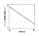
- FIG. 6 is a diagram illustrating a method for creating an optimum output calculation map in the first embodiment. It is a figure which shows the relationship between the cooling water temperature in Example 1, and the coefficient c.
- FIG. It is a figure explaining the determination method of the engine output using the system efficiency (eta) 2 which does not consider the amount of heating heat in Example 1.
- FIG. It is a figure which shows the relationship between an engine output and input fuel power in Example 1.
- FIG. It is the schematic which shows the control system of the hybrid vehicle of Example 2 of this indication. It is a figure which shows the relationship between the cooling water temperature in the modification of this indication, and the ratio of the engine emitted-heat amount with respect to power generation power.
- Example 1 A first embodiment of the present disclosure will be described with reference to FIGS. First, a schematic configuration of a control system including a control device for a hybrid vehicle will be described based on FIG.
- An engine 11 that is an internal combustion engine and a motor generator (hereinafter referred to as “MG”) 12 are mounted as power sources for the vehicle.
- the power of the output shaft (crankshaft) of the engine 11 is transmitted to the transmission 13 via the MG 12, and the power of the output shaft of the transmission 13 is transmitted to the wheels 17 via the drive shaft 14, the differential gear mechanism 15, the axle 16 and the like. Is transmitted to.
- the transmission 13 may be a stepped transmission that switches the shift speed stepwise from a plurality of shift speeds, or may be a continuously variable transmission (CVT) that shifts continuously.
- a rotary shaft of the MG 12 is connected to a mechanical connection shaft 18 that transmits the power of the engine 11 to the transmission 13 so that the power can be transmitted.
- An inverter 19 that drives the MG 12 is connected to the main battery 20, and the MG 12 exchanges power with the main battery 20 via the inverter 19.
- a hot water heating device 28 that uses heat of the cooling water of the engine 11 and an electric heating device 29 (electric heater) that generates heat by electricity are mounted.
- the electric heating device 29 is driven by electric power output from the main battery 20 or electric power output from the inverter 19.
- the accelerator sensor 21 detects the accelerator opening (the amount of operation of the accelerator pedal), and the shift switch 22 detects the operation position of the shift lever. Further, a brake operation (or a brake operation amount by a brake sensor) is detected by the brake switch 23, and a vehicle speed is detected by the vehicle speed sensor 24.
- the hybrid ECU 25 is a computer that comprehensively controls the entire vehicle, and reads the output signals of the various sensors and switches described above to detect the driving state of the vehicle.
- This hybrid ECU 25 transmits and receives control signals and data signals to and from the engine ECU 26 that controls the operation of the engine 11 and the MG-ECU 27 that controls the MG 12 by controlling the inverter 19.
- the engine 11 and the MG 12 are controlled according to the above.
- the MG 12 converts the power supplied from the main battery 20 into power and outputs it to the machine connection shaft 18 or converts the power input from the machine connection shaft 18 into power and charges the main battery 20.
- the transmission 13 increases the speed of power input from the machine connecting shaft 18 (power obtained by adding the power of the engine 11 and power of the MG 12 or power obtained by subtracting the power converted from the power of the engine 11 into power by the MG 12) or Decelerate and output to drive shaft 14.
- the hybrid ECU 25 executes an engine output setting routine shown in FIG. 4 to be described later, so that at least the required drive power, the required heating heat amount, the generated power, the input fuel power, and the heat storage amount in the cooling water of the vehicle. Is used to determine the output of the engine 11 so as to realize the required drive power using the system efficiency defined by using (hereinafter simply referred to as “system efficiency in consideration of the amount of heating heat”).
- the output of the engine 11 is determined so as to realize the required drive power under the condition that the system efficiency is high while ensuring the required amount of heating heat, and the operation that increases the efficiency of the entire system including the engine 11, the MG 12, and the like.
- the engine 11 can be operated at a point.
- the output of the engine 11 is determined so as to maximize the system efficiency in consideration of the amount of heating heat. Further, as shown in FIG. 3, when the cooling water temperature (cooling water temperature) of the engine 11 is lower than the predetermined temperature T, the ratio of the heat generation amount of the engine 11 to the power generation power (the engine heat generation amount) increases as the cooling water temperature increases.
- the output of the engine 11 is determined by determining the output of the MG 12 so that (/ power generation power) becomes smaller.
- the output of the engine 11 is determined by determining the output of the MG 12 regardless of the amount of heat generated by the engine 11.
- the engine output setting routine shown in FIG. 4 is repeatedly executed at a predetermined cycle during the power-on period of the hybrid ECU 25.
- the hybrid ECU 25 may be used as an example of a control unit that determines the output of the engine 11 so as to realize the required drive power by using the system efficiency in consideration of the amount of heating heat.
- step 101 the coolant temperature of the engine 11 detected by a coolant temperature sensor (not shown) is read. Thereafter, the process proceeds to step 102, where the required drive power is calculated by a map or a mathematical formula based on the accelerator opening, etc., and the required heating heat quantity is calculated by a map, a mathematical formula, etc. based on the vehicle interior temperature.
- the predetermined temperature T is set to, for example, a cooling water temperature that can secure a sufficient amount of heating heat. Note that information having a correlation with the cooling water temperature such as the oil temperature (the temperature of the lubricating oil of the engine 11) may be used as the substitute information of the cooling water temperature.
- step 104 determines whether the distance to the destination is a predetermined value L or less, for example, a navigation device or the like ( The determination is based on information from (not shown).
- step 104 If it is determined in step 104 that the distance to the destination is longer than the predetermined value L, the process proceeds to step 105, and whether or not high load driving is performed within the predetermined time t (for example, traveling on a highway). For example, based on information from a navigation device or the like.
- step 105 If it is predicted in this step 105 that the high load operation will not be performed within the predetermined time t, that is, if it is determined as “No” in all of the above steps 103 to 105, the routine proceeds to step 106, where the heating heat amount is reduced.
- the engine output (the output of the engine 11) is determined so as to realize the required drive power using the first system efficiency ⁇ 1 taken into consideration.
- a first optimum output calculation map corresponding to the current cooling water temperature is selected from a plurality of first optimum output calculation maps, and this first optimum output calculation is performed.
- the MG output output of MG12
- the electric heating output output of the electric heating device 29
- the MG output has a positive value on the power generation side (charging side).
- the first optimum output calculation map is created in advance based on test data, design data, etc., and is stored in the ROM of the hybrid ECU 25.
- the first optimum output calculation map is created as follows. First, required drive power Pdrv, required heating heat amount Hheat (required heating heat amount per unit time), generated power Ein (generated power), and stored heat amount Hin (heat stored amount per unit time) to the cooling water
- the fuel power Pfuel the value obtained by converting the amount of fuel injected per unit time into power
- the discharge power Eout discharge power
- the heat release amount Hout heat release amount per unit time
- a, b, and c are coefficients.
- the generated power Ein is the generated power of the MG 12 and the generator, and the system does not include the generator.
- the generated power of MG12 is used.
- the first system efficiency ⁇ 1 is changed by changing the MG output and the electric heating output for each combination of the required drive power and the required heating heat quantity. Are generated, and the MG output m1 and the electric heating output h1 at the optimum point at which the first system efficiency ⁇ 1 is maximized are calculated. Using the data of the optimum points (MG output m1 and electric heating output h1) calculated for each combination of the required drive power and the required heating heat in this way, the first optimum output calculation map (required drive power and required heating heat amount). MG output map and electric heating output map).
- the process of creating the first optimum output calculation map is performed for each cooling water temperature, and the first optimum output calculation map is created for each cooling water temperature.
- the coefficient c in the above equation (1) of the first system efficiency ⁇ 1 is changed so that the coefficient c decreases as the cooling water temperature increases.
- the engine output can be determined by determining the MG output as shown in FIG.
- the engine output is obtained by adding the MG output to the drive power. As a result, the engine output is determined so as to realize the required drive power under the condition that the first system efficiency ⁇ 1 considering the heating heat quantity is maximized.
- the required heating heat amount is calculated on the basis of the vehicle interior temperature or the like.
- the present invention is not limited to this.
- the required heating heat amount is set to a constant value to simplify the calculation process. May be.
- the first optimum output calculation map may be created as a map of MG output and a map of electric heating output using the required drive power as a parameter.
- step 103 if it is determined in step 103 that the cooling water temperature is equal to or higher than the predetermined temperature T, it is determined that the amount of heat of the cooling water is sufficiently large and the amount of heating heat can be sufficiently secured. In this case, the process proceeds to step 107, and the amount of heat generated by the engine 11 is calculated using a system efficiency (second system efficiency ⁇ 2 not considering the heating heat amount) different from the first system efficiency ⁇ 1 considering the heating heat amount. Regardless of, MG output is determined and engine output is determined.
- the MG output and the electric heating output corresponding to the current required driving power are calculated using the second optimum output calculation map.
- the second optimum output calculation map is created in advance based on test data, design data, etc., and is stored in the ROM of the hybrid ECU 25.
- the second optimum output calculation map is created as follows. First, using the required drive power Pdrv, the generated power Ein, the input fuel power Pfuel, and the discharge power Eout of the main battery 20, the second system efficiency ⁇ 2 that does not consider the amount of heating heat is expressed by the following equation (2) Define in.
- the MG output and the electric heating output are changed for each required drive power, and a contour line of the second system efficiency ⁇ 2 is created.
- the MG output m2 and the electric heating output h2 at the optimum point at which ⁇ 2 is maximum are calculated.
- a second optimum output calculation map (MG output map and electricity using the required drive power as a parameter) Create a heating output map).
- the engine output is calculated by adding the MG output to the required drive power. Ask. As a result, the engine output is determined so as to realize the required drive power under the condition that the second system efficiency ⁇ 2 not taking into account the heating heat quantity is maximized.
- step 104 If it is determined in step 104 that the distance to the destination is equal to or less than the predetermined value L, even if the heat generation of the engine 11 is promoted to increase the amount of cooling water, the vehicle stops immediately and the cooling water is It is determined that there is a high possibility that heat is dissipated wastefully. Also in this case, the process proceeds to step 107, and the engine output is determined by determining the MG output regardless of the heat generation amount of the engine 11, using the second system efficiency ⁇ 2 not considering the heating heat amount.
- step 105 when it is predicted in step 105 that the high load operation is expected within the predetermined time t, the heat generation amount of the engine 11 increases due to the high load operation, and therefore it is necessary to immediately promote the heat generation of the engine 11. Judge that there is no. Also in this case, the process proceeds to step 107, and the engine output is determined by determining the MG output regardless of the heat generation amount of the engine 11, using the second system efficiency ⁇ 2 not considering the heating heat amount.
- Pe11 and Pe12 having different times can be expressed as follows.
- Pe11 P1'- ⁇
- Pe12 P2'- ⁇
- P1 ′ and P2 ′ represent engine outputs when only the driving efficiency is considered when heating is OFF.
- (alpha) represents the power reduced with heating ON.
- the required drive power of the vehicle, the required amount of heating heat, the generated power, the amount of heat stored in the cooling water, the input fuel power, the discharge power of the main battery 20 and the amount of heat released from the engine 11 are used.
- the first system efficiency ⁇ 1 in consideration of the amount of heating heat is defined.
- the engine output is determined so as to realize the required drive power by using the first system efficiency ⁇ 1 in consideration of the amount of heating heat.
- the engine output is determined so as to realize the required drive power under the condition that the system efficiency becomes high while ensuring the required heating heat amount, and the efficiency of the entire system including the engine 11 and the MG 12 is increased.
- the engine 11 can be operated, and the fuel consumption can be improved while securing the heating heat amount of the vehicle.
- the engine output is determined so that the first system efficiency ⁇ 1 in consideration of the heating heat quantity is maximized.
- the engine 11 can be operated at an operating point at which the efficiency of the entire system is maximized, and fuel efficiency can be effectively improved.
- the higher the cooling water temperature when the cooling water temperature is lower than the predetermined temperature T, the higher the cooling water temperature, the smaller the ratio of the heat generation amount of the engine 11 to the power generation power (engine heat generation amount / power generation power) becomes smaller.
- the engine output is determined by determining the output.
- the cooling water temperature when the cooling water temperature is equal to or higher than the predetermined temperature T, it is determined that the amount of heat of the cooling water is sufficiently large and the heating heat amount can be sufficiently secured, and the heating heat amount is taken into consideration.
- the second system efficiency ⁇ 2 that is not used is used to determine the engine output by determining the MG output regardless of the heat generation amount of the engine 11.
- the engine output is determined by determining the MG output regardless of the heat generation amount of the engine 11 using the second system efficiency ⁇ 2 not considering the heating heat amount. .
- the heat generation amount of the engine 11 is increased due to the high load operation, so the heat generation of the engine 11 is immediately promoted. It is determined that it is not necessary, and the engine output is determined by determining the MG output regardless of the heat generation amount of the engine 11 using the second system efficiency ⁇ 2 not considering the heating heat amount.
- the engine output is determined by determining the MG output regardless of the heat generation amount of the engine 11 using the second system efficiency ⁇ 2 not considering the heating heat amount.
- the clutch is not provided in the power transmission path from the engine 11 to the transmission 13.
- the present invention is not limited to this.
- a clutch is provided between the engine 11 and the MG 12, A clutch may be provided between the MG 12 and the transmission 13.
- the transmission 13 may have a built-in clutch. Further, the transmission 13 may be omitted.
- Example 2 Next, a second embodiment of the present disclosure will be described with reference to FIG. However, description of substantially the same parts as those in the first embodiment will be omitted or simplified, and different parts from the first embodiment will be mainly described.
- an engine 11 and two MGs are mounted as a power source of the vehicle.
- the output shaft (crank shaft) of the engine 11, the rotation shaft of the first MG 12A, and the rotation shaft of the second MG 12B are connected via a planetary gear mechanism 30 that is a power split mechanism, and the rotation shaft of the second MG 12B is
- the drive shaft 14 is connected.
- the first MG 12A and the second MG 12B exchange power with the main battery 20 via inverters 19A and 19B, respectively.
- the MG-ECU 27 controls the first inverter 19A to control the first MG 12A, and also controls the second inverter 19B to control the second MG 12B.
- the engine output is determined so that the first system efficiency ⁇ 1 in consideration of the amount of heating heat is maximized.
- the engine output is determined by determining the MG output (the output of the first MG 12A and the output of the second MG 12B) so that the ratio of the heat generation amount of the engine 11 to the generated power decreases as the coolant temperature increases.
- the cooling water temperature is equal to or higher than the predetermined temperature T, when the distance to the destination is equal to or lower than the predetermined value L, when it is predicted that the high load operation will be performed within the predetermined time t, the heating heat amount is not considered.
- the engine output is determined so that the system efficiency ⁇ 2 of 2 is maximized. At that time, the engine output is determined by determining the MG output (the output of the first MG 12A and the output of the second MG 12B) regardless of the heat generation amount of the engine 11. Thereby, substantially the same effect as the first embodiment can be obtained.
- the engine output when the cooling water temperature is lower than the predetermined temperature T, the engine output is determined so that the first system efficiency ⁇ 1 in consideration of the heating heat amount is maximized.
- the present invention is not limited to this.
- the engine output may be determined so that the first system efficiency ⁇ 1 considering the heating heat amount is within a predetermined range including the maximum (see FIG. 2).
- the engine output when the cooling water temperature is equal to or higher than the predetermined temperature T, the engine output is determined so that the second system efficiency ⁇ 2 not considering the heating heat amount is maximized.
- the present invention is not limited to this.
- the engine output may be determined so that the second system efficiency ⁇ 2 not considering the heating heat amount is within a predetermined range including the maximum.
- the first system efficiency ⁇ 1 in consideration of the amount of heating heat is used, and the higher the cooling water temperature, the heat generation of the engine 11 with respect to the generated power.
- the engine output is determined by determining the MG output so that the amount ratio is small (see FIG. 3).
- the present invention is not limited to this.
- the engine output may be determined by determining the MG output so that the ratio of the heat generation amount of the engine 11 to the generated power decreases as the coolant temperature increases.
- the present disclosure is applied to a system including the electric heating device 29.
- the present disclosure is not limited thereto, and the present disclosure may be applied to a system not including the electric heating device. .
- the present disclosure is not limited to the hybrid vehicle having the configuration illustrated in FIGS. 1 and 10, and can be implemented by being applied to hybrid vehicles having various configurations in which an engine and MG are mounted as a power source of the vehicle.
Landscapes
- Engineering & Computer Science (AREA)
- Chemical & Material Sciences (AREA)
- Combustion & Propulsion (AREA)
- Mechanical Engineering (AREA)
- Transportation (AREA)
- Automation & Control Theory (AREA)
- General Engineering & Computer Science (AREA)
- Power Engineering (AREA)
- Control Of Vehicle Engines Or Engines For Specific Uses (AREA)
- Electric Propulsion And Braking For Vehicles (AREA)
- Hybrid Electric Vehicles (AREA)
Abstract
エンジンとMGとを搭載したハイブリッド車の制御装置は、車両の要求駆動パワーと要求暖房熱量と発電パワーと冷却水への蓄熱量と投入燃料パワーと放電パワーとエンジン(11)からの放熱量とを用いて、暖房熱量を考慮したシステム効率を定義し、このシステム効率が最大となる条件で要求駆動パワーを実現するようにエンジン(11)の出力を決定する。これにより、要求暖房熱量を確保しながらエンジン(11)やMG(モータジェネレータ)(12)等を含むシステム全体の効率が高くなる動作点でエンジン(11)を動作させる。冷却水温が所定温度よりも低い場合には、冷却水温が高いほど発電パワーに対するエンジン(11)の発熱量の比率が小さくなるようにMG(12)の出力を決めてエンジン(11)の出力を決定する。これにより、暖房のための無駄な熱生成を抑制し、ハイブリッド車の暖房熱量を確保しながら燃費を向上させることができる。
Description
本出願は、当該開示内容が参照によって本出願に組み込まれた、2015年2月17日に出願された日本特許出願2015-028184を基にしている。
本開示は、車両の動力源としてエンジンとモータジェネレータとを搭載したハイブリッド車の制御装置に関する。
近年、低燃費、低排気エミッションの社会的要請から車両の動力源としてエンジンとモータジェネレータとを搭載したハイブリッド車が注目されている。このようなハイブリッド車においては、車両の暖房熱量を確保する技術として、例えば、特許文献1(特開2005-147050号公報)に記載されたものがある。このものは、エンジンの熱を利用する暖房装置がオンで且つ冷却水温が所定値未満でバッテリの充電が必要な場合に、設定温度に対して室内温度が低いほどエンジンを効率良く運転できる充電量に対して充電量が少なくなる目標充放電量を設定することで、エンジンの発熱を促して十分な暖房熱量を得るようにしている。
ハイブリッド車において、燃費を向上させるには、エンジンやモータジェネレータ等を含むシステム全体の効率を高める必要がある。しかし、上記特許文献1の技術は、システム全体の効率は考慮されておらず、暖房熱量を確保する際に、単にモータの発電量に対するエンジンの発生熱量の割合を大きくするだけであるため、条件によってはエンジンの効率が悪化してシステム全体の効率が低下してしまい、燃費が悪化する可能性がある。
そこで、本開示の目的は、車両の暖房熱量を確保しながら燃費を向上させることができるハイブリッド車の制御装置を提供することにある。
本開示の一態様によると、ハイブリッド車は、車両の動力源として搭載されたエンジン及びモータジェネレータと、エンジンの冷却水の熱を利用する暖房装置とを備えている。ハイブリッド車の制御装置は、少なくとも車両の要求駆動パワーと要求暖房熱量と発電パワーと投入燃料パワーと冷却水への蓄熱量とを用いて定義されるシステム効率、すなわち暖房熱量を考慮したシステム効率を用いて、要求駆動パワーを実現するようにエンジンの出力を決定する制御部を備える。
この構成では、制御部は、暖房熱量を考慮したシステム効率を用いて、要求駆動パワーを実現するようにエンジンの出力を決定する。したがって、要求暖房熱量を確保しながら、システム効率が高くなる条件で要求駆動パワーを実現するようにエンジンの出力を決定することができる。これにより、要求暖房熱量を確保しながら、エンジンやモータジェネレータ等を含むシステム全体の効率が高くなる動作点でエンジンを動作させることが可能となり、車両の暖房熱量を確保しながら燃費を向上させることができる。
以下に、図面を参照しながら本開示を実施するための複数の形態を説明する。各形態において先行する形態で説明した事項に対応する部分には同一の参照符号を付して重複する説明を省略する場合がある。各形態において構成の一部のみを説明している場合は、構成の他の部分については先行して説明した他の形態を適用することができる。各実施形態で具体的に組合せが可能であることを明示している部分同士の組合せばかりではなく、特に組合せに支障が生じなければ、明示してなくとも実施形態同士を部分的に組み合せることも可能である。
(実施例1)
本開示の実施例1を図1乃至図9に基づいて説明する。まず、図1に基づいてハイブリッド車用の制御装置を含む制御システムの概略構成を説明する。
本開示の実施例1を図1乃至図9に基づいて説明する。まず、図1に基づいてハイブリッド車用の制御装置を含む制御システムの概略構成を説明する。
車両の動力源として内燃機関であるエンジン11とモータジェネレータ(以下「MG」と表記する)12とが搭載されている。エンジン11の出力軸(クランク軸)の動力がMG12を介して変速機13に伝達され、この変速機13の出力軸の動力が駆動軸14、ディファレンシャルギヤ機構15、車軸16等を介して車輪17に伝達される。変速機13は、複数段の変速段の中から変速段を段階的に切り換える有段変速機であっても良いし、無段階に変速する無段変速機(CVT)であっても良い。エンジン11の動力を変速機13に伝達する機械接続軸18の途中に、MG12の回転軸が動力伝達可能に連結されている。また、MG12を駆動するインバータ19がメインバッテリ20に接続され、MG12がインバータ19を介してメインバッテリ20と電力を授受するようになっている。
車室内を暖房するための暖房装置として、エンジン11の冷却水の熱を利用する温水暖房装置28と、電気で熱を発生させる電気暖房装置29(電気ヒータ)とが搭載されている。電気暖房装置29は、メインバッテリ20から出力される電力又はインバータ19から出力される電力により駆動される。
また、アクセルセンサ21によってアクセル開度(アクセルペダルの操作量)が検出され、シフトスイッチ22によってシフトレバーの操作位置が検出される。更に、ブレーキスイッチ23によってブレーキ操作(又はブレーキセンサによってブレーキ操作量)が検出され、車速センサ24によって車速が検出される。
ハイブリッドECU25は、車両全体を総合的に制御するコンピュータであり、上述した各種のセンサやスイッチの出力信号を読み込んで、車両の運転状態を検出する。このハイブリッドECU25は、エンジン11の運転を制御するエンジンECU26やインバータ19を制御してMG12を制御するMG-ECU27との間で制御信号やデータ信号を送受信し、各ECU26,27によって車両の運転状態に応じて、エンジン11やMG12等を制御する。
その際、MG12は、メインバッテリ20から供給される電力を動力に変換して機械接続軸18に出力するか又は機械接続軸18から入力される動力を電力に変換してメインバッテリ20に充電する。変速機13は、機械接続軸18から入力される動力(エンジン11の動力とMG12の動力を合算した動力又はエンジン11の動力からMG12で電力に変換された動力を差し引いた動力)を増速又は減速して駆動軸14に出力する。
ところで、ハイブリッド車において、燃費を向上させるには、エンジン11やMG12等を含むシステム全体の効率を高める必要がある。そこで、本実施例1では、ハイブリッドECU25により後述する図4のエンジン出力設定ルーチンを実行することで、少なくとも車両の要求駆動パワーと要求暖房熱量と発電パワーと投入燃料パワーと冷却水への蓄熱量とを用いて定義されるシステム効率(以下単に「暖房熱量を考慮したシステム効率」という)を用いて、要求駆動パワーを実現するようにエンジン11の出力を決定する。これにより、要求暖房熱量を確保しながら、システム効率が高くなる条件で要求駆動パワーを実現するようにエンジン11の出力を決定して、エンジン11やMG12等を含むシステム全体の効率が高くなる動作点でエンジン11を動作させることが可能となる。
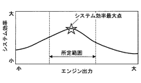
この際、本実施例1では、図2に示すように、暖房熱量を考慮したシステム効率が最大になるようにエンジン11の出力を決定する。更に、図3に示すように、エンジン11の冷却水温(冷却水の温度)が所定温度Tよりも低い場合には、冷却水温が高いほど発電パワーに対するエンジン11の発熱量の比率(エンジン発熱量/発電パワー)が小さくなるようにMG12の出力を決めてエンジン11の出力を決定する。
一方、図3に示すように、エンジン11の冷却水温が所定温度T以上の場合には、暖房熱量を考慮したシステム効率とは別のシステム効率(暖房熱量を考慮していないシステム効率)を用いて、エンジン11の発熱量とは無関係にMG12の出力を決めてエンジン11の出力を決定する。
以下、本実施例1で、ハイブリッドECU25が実行する図4のエンジン出力設定ルーチンの処理内容を説明する。図4に示すエンジン出力設定ルーチンは、ハイブリッドECU25の電源オン期間中に所定周期で繰り返し実行される。ハイブリッドECU25は、暖房熱量を考慮したシステム効率を用いて、要求駆動パワーを実現するようにエンジン11の出力を決定する制御部の一例として用いられてもよい。
本ルーチンが起動されると、まず、ステップ101で、冷却水温センサ(図示せず)で検出したエンジン11の冷却水温を読み込む。この後、ステップ102に進み、アクセル開度等に基づいて要求駆動パワーをマップ又は数式等により算出し、車室内温度等に基づいて要求暖房熱量をマップ又は数式等により算出する。
この後、ステップ103に進み、冷却水温が所定温度T以上であるか否かを判定する。この所定温度Tは、例えば、暖房熱量を十分に確保できる冷却水温に設定されている。尚、冷却水温の代用情報として、油温(エンジン11の潤滑油の温度)等の冷却水温と相関関係を有する情報を用いるようにしても良い。
このステップ103で、冷却水温が所定温度Tよりも低いと判定された場合には、ステップ104に進み、目的地までの距離が所定値L以下であるか否かを、例えば、ナビゲーション装置等(図示せず)からの情報に基づいて判定する。
このステップ104で、目的地までの距離が所定値Lよりも長いと判定された場合には、ステップ105に進み、所定時間t以内に高負荷運転になる(例えば高速道路を走行する)か否を、例えば、ナビゲーション装置等からの情報に基づいて予測する。
このステップ105で、所定時間t以内には高負荷運転にならないと予測された場合、つまり、上記ステップ103~105で全て「No」と判定された場合には、ステップ106に進み、暖房熱量を考慮した第1のシステム効率η1 を用いて、要求駆動パワーを実現するようにエンジン出力(エンジン11の出力)を決定する。
具体的には、図5に示すように、複数の第1の最適出力算出マップの中から、現在の冷却水温に応じた第1の最適出力算出マップを選択し、この第1の最適出力算出マップを用いて、現在の要求駆動パワーと要求暖房熱量とに応じたMG出力(MG12の出力)と電気暖房出力(電気暖房装置29の出力)を算出する。尚、MG出力は、発電側(充電側)を正の値とする。第1の最適出力算出マップは、予め試験データや設計データ等に基づいて作成され、ハイブリッドECU25のROMに記憶されている。
第1の最適出力算出マップは、次のようにして作成されている。まず、要求駆動パワーPdrv と、要求暖房熱量Hheat(単位時間当りの要求暖房熱量)と、発電パワーEin(発電電力)と、冷却水への蓄熱量Hin(単位時間当りの蓄熱量)と、投入燃料パワーPfuel(単位時間当りの噴射燃料量をパワーに換算した値)と、メインバッテリ20の放電パワーEout (放電電力)と、エンジン11からの放熱量Hout (単位時間当りの放熱量)とを用いて、暖房熱量を考慮した第1のシステム効率η1 を下記(1)式で定義する。

図6に示すように、この暖房熱量を考慮した第1のシステム効率η1 において、要求駆動パワーと要求暖房熱量の組み合わせ毎に、MG出力と電気暖房出力を変化させて、第1のシステム効率η1 の等高線を作成し、第1のシステム効率η1 が最大となる最適点のMG出力m1 と電気暖房出力h1 を算出する。このようにして要求駆動パワーと要求暖房熱量の組み合わせ毎に算出した最適点(MG出力m1 と電気暖房出力h1 )のデータを用いて、第1の最適出力算出マップ(要求駆動パワーと要求暖房熱量をパラメータとするMG出力のマップと電気暖房出力のマップ)を作成する。
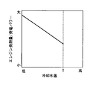
この第1の最適出力算出マップを作成する処理を冷却水温毎に実施して、冷却水温毎に第1の最適出力算出マップを作成する。この際、図7に示すように、第1のシステム効率η1 の上記(1)式における係数cを、冷却水温が高いほど係数cが小さくなるように変化させる。これにより、冷却水温が高いほど冷却水への蓄熱量がシステム効率η1 に与える影響が大きくなり、冷却水温が高いほど発電パワーに対するエンジン11の発熱量の比率(エンジン発熱量/発電パワー)が小さくなる(図3参照)ようにMG出力を決めてエンジン出力を決定することができる。
図5に示すように、現在の冷却水温に応じた第1の最適出力算出マップを用いて、現在の要求駆動パワーと要求暖房熱量とに応じたMG出力と電気暖房出力を算出した後、要求駆動パワーにMG出力を加算してエンジン出力を求める。これにより、暖房熱量を考慮した第1のシステム効率η1 が最大になる条件で要求駆動パワーを実現するようにエンジン出力を決定する。
尚、本ルーチンでは、車室内温度等に基づいて要求暖房熱量を算出するようにしているが、これに限定されず、例えば、要求暖房熱量を一定値にして、演算処理を簡略化するようにしても良い。この場合、第1の最適出力算出マップは、要求駆動パワーをパラメータとするMG出力のマップと電気暖房出力のマップを作成すれば良い。
一方、上記ステップ103で、冷却水温が所定温度T以上と判定された場合には、冷却水の熱量が十分に大きく、暖房熱量を十分に確保できる状態であると判断する。この場合、ステップ107に進み、暖房熱量を考慮した第1のシステム効率η1 とは別のシステム効率(暖房熱量を考慮していない第2のシステム効率η2 )を用いて、エンジン11の発熱量とは無関係にMG出力を決めてエンジン出力を決定する。
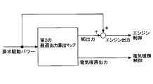
具体的には、図8に示すように、第2の最適出力算出マップを用いて、現在の要求駆動パワーに応じたMG出力と電気暖房出力を算出する。第2の最適出力算出マップは、予め試験データや設計データ等に基づいて作成され、ハイブリッドECU25のROMに記憶されている。
第2の最適出力算出マップは、次のようにして作成されている。まず、要求駆動パワーPdrv と、発電パワーEinと、投入燃料パワーPfuelと、メインバッテリ20の放電パワーEout とを用いて、暖房熱量を考慮していない第2のシステム効率η2 を下記(2)式で定義する。

図8に示すように、第2の最適出力算出マップを用いて、現在の要求駆動パワーに応じたMG出力と電気暖房出力を算出した後、要求駆動パワーにMG出力を加算してエンジン出力を求める。これにより、暖房熱量を考慮していない第2のシステム効率η2 が最大になる条件で要求駆動パワーを実現するようにエンジン出力を決定する。
また、上記ステップ104で、目的地までの距離が所定値L以下と判定された場合には、エンジン11の発熱を促進して冷却水の熱量を増加させても、直ぐに停車して冷却水の熱が無駄に放熱される可能性が高いと判断する。この場合も、ステップ107に進み、暖房熱量を考慮していない第2のシステム効率η2 を用いて、エンジン11の発熱量とは無関係にMG出力を決めてエンジン出力を決定する。
また、上記ステップ105で、所定時間t以内に高負荷運転になると予測された場合には、いずれ高負荷運転になってエンジン11の発熱量が増加するため、直ぐにエンジン11の発熱を促進する必要はないと判断する。この場合も、ステップ107に進み、暖房熱量を考慮していない第2のシステム効率η2 を用いて、エンジン11の発熱量とは無関係にMG出力を決めてエンジン出力を決定する。
次に、本実施例1の提案手法(システム効率を用いてエンジン出力を決定する方法)によってエンジン出力を適切に設定することにより、比較手法(システム効率を用いずにエンジン出力を決定する方法)に比べて、投入燃料エネルギを減少させることができることを説明する。
比較手法の場合、時刻が異なる2点のエンジン出力Pe11 ,Pe12 を、次のように表現できると仮定する。
Pe11 =P1'-α
Pe12 =P2'-α
ここで、P1',P2'は、暖房OFFの場合に駆動の効率だけを考えた場合のエンジン出力を表す。また、αは、暖房ONに伴って減少させるパワーを表す。
Pe11 =P1'-α
Pe12 =P2'-α
ここで、P1',P2'は、暖房OFFの場合に駆動の効率だけを考えた場合のエンジン出力を表す。また、αは、暖房ONに伴って減少させるパワーを表す。
一方、提案手法の場合、時刻が異なる2点のエンジン出力Pe11 ,Pe12 を、次のように表現できると仮定する。
Pe11 =P1'-β
Pe12 =P2'-γ
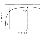
ここで、β,γは、暖房ONに伴って減少させるパワーを表す(図9参照)。減少させるエンジン出力を比較手法の場合と同一にするために、2α=β+γとする。
Pe11 =P1'-β
Pe12 =P2'-γ
ここで、β,γは、暖房ONに伴って減少させるパワーを表す(図9参照)。減少させるエンジン出力を比較手法の場合と同一にするために、2α=β+γとする。
次に、エンジン出力と投入燃料パワーの関係を表す関数をf(Pe )とおくと、比較手法の場合の投入燃料パワーE1allと提案手法の場合の投入燃料パワーE2allは、次のように表現することができる。
E1all=f(P1'-α)+f(P2'-α)
E2all=f(P1'-β)+f(P2'-γ)
ここで、狙いの条件である、比較手法よりも提案手法の方が投入燃料エネルギが少なくなる場合、つまり、E1all>E2allとなる場合を考えると、次の関係が成り立つ。
f(P1'-α)+f(P2'-α)>f(P1'-β)+f(P2'-γ)
f(P1'-α)+f(P2'-α)-f(P1'-β)-f(P2'-γ)>0 …(3)
また、減少パワーx(α,β,γ)がエンジン出力P1',P2'に比べて小さい場合、係数δ=f' (P1')、係数ε=f' (P2')とすると、f(P1'-x),f(P2'-x)は、次のように表すことができる。
f(P1'-x)=f(P1')-δx
f(P2'-x)=f(P2')-εx
これらの関係を用いて、上記(3)式を次のように変形することができる。
-δα-εα+δβ+εγ>0
δ(β-α)+ε(γ-α)>0
δ(β-α)>ε(α-γ)
この式に、2α=β+γ、つまり、α=(β+γ)/2を代入すると、次の式を得ることができる。
δ(β-γ)/2>ε(β-γ)/2
δ(β-γ)>ε(β-γ)
以上により、(a) β>γの場合には、δ>εとなるようにエンジン出力の減少量を決定し、(b) β<γの場合には、δ<εとなるようにエンジン出力の減少量を決定することで、提案手法により投入燃料エネルギを比較手法に比べて減らすことができる。
E1all=f(P1'-α)+f(P2'-α)
E2all=f(P1'-β)+f(P2'-γ)
ここで、狙いの条件である、比較手法よりも提案手法の方が投入燃料エネルギが少なくなる場合、つまり、E1all>E2allとなる場合を考えると、次の関係が成り立つ。
f(P1'-α)+f(P2'-α)>f(P1'-β)+f(P2'-γ)
f(P1'-α)+f(P2'-α)-f(P1'-β)-f(P2'-γ)>0 …(3)
また、減少パワーx(α,β,γ)がエンジン出力P1',P2'に比べて小さい場合、係数δ=f' (P1')、係数ε=f' (P2')とすると、f(P1'-x),f(P2'-x)は、次のように表すことができる。
f(P1'-x)=f(P1')-δx
f(P2'-x)=f(P2')-εx
これらの関係を用いて、上記(3)式を次のように変形することができる。
-δα-εα+δβ+εγ>0
δ(β-α)+ε(γ-α)>0
δ(β-α)>ε(α-γ)
この式に、2α=β+γ、つまり、α=(β+γ)/2を代入すると、次の式を得ることができる。
δ(β-γ)/2>ε(β-γ)/2
δ(β-γ)>ε(β-γ)
以上により、(a) β>γの場合には、δ>εとなるようにエンジン出力の減少量を決定し、(b) β<γの場合には、δ<εとなるようにエンジン出力の減少量を決定することで、提案手法により投入燃料エネルギを比較手法に比べて減らすことができる。
以上説明した本実施例1では、車両の要求駆動パワーと要求暖房熱量と発電パワーと冷却水への蓄熱量と投入燃料パワーとメインバッテリ20の放電パワーとエンジン11からの放熱量とを用いて、暖房熱量を考慮した第1のシステム効率η1 を定義する。そして、この暖房熱量を考慮した第1のシステム効率η1 を用いて、要求駆動パワーを実現するようにエンジン出力を決定するようにしている。これにより、要求暖房熱量を確保しながら、システム効率が高くなる条件で要求駆動パワーを実現するようにエンジン出力を決定して、エンジン11やMG12等を含むシステム全体の効率が高くなる動作点でエンジン11を動作させることが可能となり、車両の暖房熱量を確保しながら燃費を向上させることができる。
また、本実施例1では、暖房熱量を考慮した第1のシステム効率η1 が最大になるようにエンジン出力を決定するようにしている。これにより、システム全体の効率が最大になる動作点でエンジン11を動作させることができ、燃費を効果的に向上させることができる。
更に、本実施例1では、冷却水温が所定温度Tよりも低い場合には、冷却水温が高いほど発電パワーに対するエンジン11の発熱量の比率(エンジン発熱量/発電パワー)が小さくなるようにMG出力を決めてエンジン出力を決定するようにしている。これにより、冷却水温が高いほど、冷却水の熱量が増加して、要求暖房熱量に対する不足分(暖房のために発生させる必要がある熱量)が少なくなるのに対応して、発電パワーに対するエンジン11の発熱量の比率を小さくすることができ、暖房のための無駄な熱生成を抑制することができる。
一方、本実施例1では、冷却水温が所定温度T以上の場合には、冷却水の熱量が十分に大きく、暖房熱量を十分に確保できる状態であると判断して、暖房熱量を考慮していない第2のシステム効率η2 を用いて、エンジン11の発熱量とは無関係にMG出力を決めてエンジン出力を決定するようにしている。これにより、冷却水温が所定温度T以上の場合には、暖房熱量を考慮せずに燃費優先でMG出力やエンジン出力を決定することができ、燃費の向上効果を高めることができる。
また、本実施例1では、目的地までの距離が所定値L以下の場合には、エンジン11の発熱を促進して冷却水の熱量を増加させても、直ぐに停車して冷却水の熱が無駄に放熱される可能性が高いと判断して、暖房熱量を考慮していない第2のシステム効率η2 を用いて、エンジン11の発熱量とは無関係にMG出力を決めてエンジン出力を決定する。これにより、目的地までの距離が所定値L以下の場合には、暖房熱量を考慮せずに燃費優先でMG出力やエンジン出力を決定することができ、燃費の向上効果を高めることができる。
更に、本実施例1では、所定時間t以内に高負荷運転になると予測される場合には、いずれ高負荷運転になってエンジン11の発熱量が増加するため、直ぐにエンジン11の発熱を促進する必要はないと判断して、暖房熱量を考慮していない第2のシステム効率η2 を用いて、エンジン11の発熱量とは無関係にMG出力を決めてエンジン出力を決定する。これにより、所定時間t以内に高負荷運転になると予測される場合には、暖房熱量を考慮せずに燃費優先でMG出力やエンジン出力を決定することができ、燃費の向上効果を高めることができる。
尚、上記実施例1では、エンジン11から変速機13までの動力伝達経路にクラッチを設けない構成としたが、これに限定されず、例えば、エンジン11とMG12との間にクラッチを設けたり、MG12と変速機13との間にクラッチを設けた構成としても良い。或は、変速機13にクラッチを内蔵した構成としても良い。また、変速機13を省略した構成としても良い。
(実施例2)
次に、図10を用いて本開示の実施例2を説明する。但し、前記実施例1と実質的に同一部分については説明を省略又は簡略化し、主として前記実施例1と異なる部分について説明する。
次に、図10を用いて本開示の実施例2を説明する。但し、前記実施例1と実質的に同一部分については説明を省略又は簡略化し、主として前記実施例1と異なる部分について説明する。
本実施例2では、図10に示すように、車両の動力源としてエンジン11と二つのMG(第1のMG12A及び第2のMG12B)とが搭載されている。エンジン11の出力軸(クランク軸)と第1のMG12Aの回転軸と第2のMG12Bの回転軸とが動力分割機構である遊星歯車機構30を介して連結され、第2のMG12Bの回転軸が駆動軸14に連結されている。
第1のMG12Aと第2のMG12Bは、それぞれインバータ19A,19Bを介してメインバッテリ20と電力を授受するようになっている。MG-ECU27は、第1のインバータ19Aを制御して第1のMG12Aを制御すると共に、第2のインバータ19Bを制御して第2のMG12Bを制御する。
本実施例2においても、冷却水温が所定温度Tよりも低い場合には、暖房熱量を考慮した第1のシステム効率η1 が最大になるようにエンジン出力を決定する。その際、冷却水温が高いほど発電パワーに対するエンジン11の発熱量の比率が小さくなるようにMG出力(第1のMG12Aの出力と第2のMG12Bの出力)を決めてエンジン出力を決定する。一方、冷却水温が所定温度T以上の場合、目的地までの距離が所定値L以下の場合、所定時間t以内に高負荷運転になると予測される場合には、暖房熱量を考慮していない第2のシステム効率η2 が最大になるようにエンジン出力を決定する。その際、エンジン11の発熱量とは無関係にMG出力(第1のMG12Aの出力と第2のMG12Bの出力)を決めてエンジン出力を決定する。これにより、前記実施例1とほぼ同じ効果を得ることができる。
尚、上記各実施例1,2では、冷却水温が所定温度Tよりも低い場合に、暖房熱量を考慮した第1のシステム効率η1 が最大になるようにエンジン出力を決定するようにしたが、これに限定されず、例えば、暖房熱量を考慮した第1のシステム効率η1 が最大を含む所定範囲(図2参照)内になるようにエンジン出力を決定するようにしても良い。
また、上記各実施例1,2では、冷却水温が所定温度T以上の場合に、暖房熱量を考慮していない第2のシステム効率η2 が最大になるようにエンジン出力を決定するようにしたが、これに限定されず、例えば、暖房熱量を考慮していない第2のシステム効率η2 が最大を含む所定範囲内になるようにエンジン出力を決定するようにしても良い。
また、上記各実施例1,2では、冷却水温が所定温度Tよりも低い場合に、暖房熱量を考慮した第1のシステム効率η1 を用いて、冷却水温が高いほど発電パワーに対するエンジン11の発熱量の比率が小さくなるようにMG出力を決めてエンジン出力を決定するようにしている(図3参照)。しかし、これに限定されず、例えば、図11に示すように、冷却水温が所定温度Tよりも低いか否かに拘らず全ての冷却水温領域で、暖房熱量を考慮した第1のシステム効率η1 を用いて、冷却水温が高いほど発電パワーに対するエンジン11の発熱量の比率が小さくなるようにMG出力を決めてエンジン出力を決定するようにしても良い。
また、上記各実施例1,2では、電気暖房装置29を備えたシステムに本開示を適用したが、これに限定されず、電気暖房装置を備えていないシステムに本開示を適用しても良い。
その他、本開示は、図1及び図10に示す構成のハイブリッド車に限定されず、車両の動力源としてエンジンとMGとを搭載した種々の構成のハイブリッド車に適用して実施できる。
本開示は、実施例に準拠して記述されたが、本開示は当該実施例や構造に限定されるものではないと理解される。本開示は、様々な変形例や均等範囲内の変形をも包含する。加えて、様々な組み合わせや形態、さらには、それらに一要素のみ、それ以上、あるいはそれ以下、を含む他の組み合わせや形態をも、本開示の範疇や思想範囲に入るものである。
Claims (6)
- 車両の動力源として搭載されたエンジン(11)及びモータジェネレータ(12,12A,12B)と、前記エンジン(11)の冷却水の熱を利用する暖房装置(28)とを備えたハイブリッド車用の制御装置において、
少なくとも前記車両の要求駆動パワーと要求暖房熱量と発電パワーと投入燃料パワーと前記冷却水への蓄熱量とを用いて定義されるシステム効率、すなわち暖房熱量を考慮したシステム効率を用いて、前記要求駆動パワーを実現するように前記エンジン(11)の出力を決定する制御部(25)を備えているハイブリッド車の制御装置。 - 前記制御部(25)は、前記暖房熱量を考慮したシステム効率が最大又は該最大を含む所定範囲内になるように前記エンジン(11)の出力を決定する請求項1に記載のハイブリッド車の制御装置。
- 前記制御部(25)は、前記冷却水の温度が高いほど前記発電パワーに対する前記エンジン(11)の発熱量の比率が小さくなるように前記モータジェネレータ(12,12A,12B)の出力を決めて前記エンジン(11)の出力を決定する請求項1又は2に記載のハイブリッド車の制御装置。
- 前記制御部(25)は、前記冷却水の温度が所定温度以上の場合には、前記暖房熱量を考慮したシステム効率とは別のシステム効率を用いて、前記エンジン(11)の発熱量とは無関係に前記モータジェネレータ(12,12A,12B)の出力を決めて前記エンジン(11)の出力を決定する請求項1乃至3のいずれかに記載のハイブリッド車の制御装置。
- 前記制御部(25)は、前記車両の目的地までの距離が所定値以下の場合には、前記暖房熱量を考慮したシステム効率とは別のシステム効率を用いて、前記エンジン(11)の発熱量とは無関係に前記モータジェネレータ(12,12A,12B)の出力を決めて前記エンジン(11)の出力を決定する請求項1乃至4のいずれかに記載のハイブリッド車の制御装置。
- 前記制御部(25)は、所定時間以内に高負荷運転になると予測される場合には、前記暖房熱量を考慮したシステム効率とは別のシステム効率を用いて、前記エンジン(11)の発熱量とは無関係に前記モータジェネレータ(12,12A,12B)の出力を決めて前記エンジン(11)の出力を決定する請求項1乃至5のいずれかに記載のハイブリッド車の制御装置。
Applications Claiming Priority (2)
| Application Number | Priority Date | Filing Date | Title |
|---|---|---|---|
| JP2015028184A JP2016150628A (ja) | 2015-02-17 | 2015-02-17 | ハイブリッド車の制御装置 |
| JP2015-028184 | 2015-02-17 |
Publications (1)
| Publication Number | Publication Date |
|---|---|
| WO2016132710A1 true WO2016132710A1 (ja) | 2016-08-25 |
Family
ID=56692273
Family Applications (1)
| Application Number | Title | Priority Date | Filing Date |
|---|---|---|---|
| PCT/JP2016/000662 Ceased WO2016132710A1 (ja) | 2015-02-17 | 2016-02-09 | ハイブリッド車の制御装置 |
Country Status (2)
| Country | Link |
|---|---|
| JP (1) | JP2016150628A (ja) |
| WO (1) | WO2016132710A1 (ja) |
Cited By (1)
| Publication number | Priority date | Publication date | Assignee | Title |
|---|---|---|---|---|
| CN115370494A (zh) * | 2022-09-13 | 2022-11-22 | 中国第一汽车股份有限公司 | 混合动力车型的发电效率优化方法、装置及行驶控制方法 |
Families Citing this family (1)
| Publication number | Priority date | Publication date | Assignee | Title |
|---|---|---|---|---|
| KR102394843B1 (ko) * | 2017-12-27 | 2022-05-06 | 현대자동차주식회사 | Phev 차량의 cd 모드 난방시 엔진 파워 제어 방법 |
Citations (3)
| Publication number | Priority date | Publication date | Assignee | Title |
|---|---|---|---|---|
| JP2005147050A (ja) * | 2003-11-18 | 2005-06-09 | Toyota Motor Corp | 自動車 |
| JP2014198495A (ja) * | 2013-03-29 | 2014-10-23 | 株式会社デンソー | ハイブリッド車の制御装置 |
| JP2014201100A (ja) * | 2013-04-02 | 2014-10-27 | 株式会社デンソー | ハイブリッド車の制御装置 |
-
2015
- 2015-02-17 JP JP2015028184A patent/JP2016150628A/ja active Pending
-
2016
- 2016-02-09 WO PCT/JP2016/000662 patent/WO2016132710A1/ja not_active Ceased
Patent Citations (3)
| Publication number | Priority date | Publication date | Assignee | Title |
|---|---|---|---|---|
| JP2005147050A (ja) * | 2003-11-18 | 2005-06-09 | Toyota Motor Corp | 自動車 |
| JP2014198495A (ja) * | 2013-03-29 | 2014-10-23 | 株式会社デンソー | ハイブリッド車の制御装置 |
| JP2014201100A (ja) * | 2013-04-02 | 2014-10-27 | 株式会社デンソー | ハイブリッド車の制御装置 |
Cited By (2)
| Publication number | Priority date | Publication date | Assignee | Title |
|---|---|---|---|---|
| CN115370494A (zh) * | 2022-09-13 | 2022-11-22 | 中国第一汽车股份有限公司 | 混合动力车型的发电效率优化方法、装置及行驶控制方法 |
| CN115370494B (zh) * | 2022-09-13 | 2025-08-01 | 中国第一汽车股份有限公司 | 混合动力车型的发电效率优化方法、装置及行驶控制方法 |
Also Published As
| Publication number | Publication date |
|---|---|
| JP2016150628A (ja) | 2016-08-22 |
Similar Documents
| Publication | Publication Date | Title |
|---|---|---|
| US9327609B2 (en) | Controller for hybrid vehicle | |
| JP6436071B2 (ja) | 車両の制御装置 | |
| JP5198147B2 (ja) | 車両およびその制御方法並びに駆動装置 | |
| JP6089887B2 (ja) | ハイブリッド車の制御装置 | |
| US20150006000A1 (en) | Control system and control method for hybrid vehicle | |
| EP3501869B1 (en) | Drive force control system for hybrid vehicles | |
| US20160121707A1 (en) | Hybrid vehicle | |
| CN110386126B (zh) | 混合动力车辆的控制系统 | |
| US9371069B2 (en) | Apparatus and method for controlling engine clutch of hybrid electric vehicle | |
| CN103786592A (zh) | 用于控制混合动力车的充电的方法和系统 | |
| JP2017144899A (ja) | 車両用駆動装置の制御装置 | |
| JP5277198B2 (ja) | ハイブリッド車両制御装置 | |
| JP6268118B2 (ja) | ハイブリッド自動車の制御装置 | |
| JP2011121423A (ja) | 車両駆動システムの制御装置 | |
| JP4254497B2 (ja) | 自動車 | |
| WO2016132710A1 (ja) | ハイブリッド車の制御装置 | |
| JP6032147B2 (ja) | ハイブリッド車両の制御装置 | |
| US9096223B2 (en) | Hybrid vehicle control apparatus | |
| US20240308517A1 (en) | Method of controlling charging by motor to improve fuel efficiency of hybrid vehicle | |
| Steffan et al. | Potentials of a 48 volt belt-starter-generator in the powertrain of an ultra-light vehicle | |
| JP2017020483A (ja) | 車両のエンジン運転制御装置及びその方法 | |
| JP6128023B2 (ja) | 車両の制御装置 | |
| JP6070531B2 (ja) | ハイブリッド車の制御装置 | |
| JP4386003B2 (ja) | ハイブリッド車両のバッテリ保護制御装置 | |
| JP5810580B2 (ja) | 車両および車両用制御方法 |
Legal Events
| Date | Code | Title | Description |
|---|---|---|---|
| 121 | Ep: the epo has been informed by wipo that ep was designated in this application |
Ref document number: 16752100 Country of ref document: EP Kind code of ref document: A1 |
|
| NENP | Non-entry into the national phase |
Ref country code: DE |
|
| 122 | Ep: pct application non-entry in european phase |
Ref document number: 16752100 Country of ref document: EP Kind code of ref document: A1 |