WO2016132553A1 - 対象物高さ推定装置及び画像読取装置 - Google Patents
対象物高さ推定装置及び画像読取装置 Download PDFInfo
- Publication number
- WO2016132553A1 WO2016132553A1 PCT/JP2015/054881 JP2015054881W WO2016132553A1 WO 2016132553 A1 WO2016132553 A1 WO 2016132553A1 JP 2015054881 W JP2015054881 W JP 2015054881W WO 2016132553 A1 WO2016132553 A1 WO 2016132553A1
- Authority
- WO
- WIPO (PCT)
- Prior art keywords
- linear light
- unit
- imaging
- reading
- area
- Prior art date
- Legal status (The legal status is an assumption and is not a legal conclusion. Google has not performed a legal analysis and makes no representation as to the accuracy of the status listed.)
- Ceased
Links
Images
















Classifications
-
- G—PHYSICS
- G01—MEASURING; TESTING
- G01B—MEASURING LENGTH, THICKNESS OR SIMILAR LINEAR DIMENSIONS; MEASURING ANGLES; MEASURING AREAS; MEASURING IRREGULARITIES OF SURFACES OR CONTOURS
- G01B11/00—Measuring arrangements characterised by the use of optical techniques
- G01B11/24—Measuring arrangements characterised by the use of optical techniques for measuring contours or curvatures
- G01B11/25—Measuring arrangements characterised by the use of optical techniques for measuring contours or curvatures by projecting a pattern, e.g. one or more lines, moiré fringes on the object
-
- H—ELECTRICITY
- H04—ELECTRIC COMMUNICATION TECHNIQUE
- H04N—PICTORIAL COMMUNICATION, e.g. TELEVISION
- H04N23/00—Cameras or camera modules comprising electronic image sensors; Control thereof
- H04N23/60—Control of cameras or camera modules
-
- H—ELECTRICITY
- H04—ELECTRIC COMMUNICATION TECHNIQUE
- H04N—PICTORIAL COMMUNICATION, e.g. TELEVISION
- H04N1/00—Scanning, transmission or reproduction of documents or the like, e.g. facsimile transmission; Details thereof
- H04N1/04—Scanning arrangements, i.e. arrangements for the displacement of active reading or reproducing elements relative to the original or reproducing medium, or vice versa
- H04N1/10—Scanning arrangements, i.e. arrangements for the displacement of active reading or reproducing elements relative to the original or reproducing medium, or vice versa using flat picture-bearing surfaces
-
- H—ELECTRICITY
- H04—ELECTRIC COMMUNICATION TECHNIQUE
- H04N—PICTORIAL COMMUNICATION, e.g. TELEVISION
- H04N1/00—Scanning, transmission or reproduction of documents or the like, e.g. facsimile transmission; Details thereof
- H04N1/04—Scanning arrangements, i.e. arrangements for the displacement of active reading or reproducing elements relative to the original or reproducing medium, or vice versa
- H04N1/10—Scanning arrangements, i.e. arrangements for the displacement of active reading or reproducing elements relative to the original or reproducing medium, or vice versa using flat picture-bearing surfaces
- H04N1/107—Scanning arrangements, i.e. arrangements for the displacement of active reading or reproducing elements relative to the original or reproducing medium, or vice versa using flat picture-bearing surfaces with manual scanning
-
- H—ELECTRICITY
- H04—ELECTRIC COMMUNICATION TECHNIQUE
- H04N—PICTORIAL COMMUNICATION, e.g. TELEVISION
- H04N5/00—Details of television systems
- H04N5/222—Studio circuitry; Studio devices; Studio equipment
Definitions
- the present invention relates to an object height estimation apparatus and an image reading apparatus.
- Such a method of digitizing a binding medium includes a method in which a binding medium is separated into one medium and each image is read by a normal image reading apparatus, and a binding medium is not separated and binding is performed. There is a method of reading an image on a binding medium while turning the medium. In the latter case, there has been proposed an image reading apparatus that reads an opened binding medium at a time and manually turns the binding medium (for example, Patent Documents 1 to 4).
- Patent Documents 1 to 4 image processing such as object size detection and distortion correction is enhanced when scanning a binding medium as an object to be digitized.
- image processing such as object size detection and distortion correction is enhanced when scanning a binding medium as an object to be digitized.
- it is necessary to detect the three-dimensional shape of the object with high accuracy.
- Patent Documents 5 and 6 disclose a technique for detecting a three-dimensional shape of an object using a laser and a camera. For example, in the technique described in Patent Document 5, laser light irradiated on an object is acquired by a camera, and the height of the object is measured by a known triangulation method.
- Patent Document 7 discloses a technique for detecting a three-dimensional shape of an object using infrared rays.
- the laser beam irradiated to the target object is acquired with a camera, and the height of a target object is measured by a publicly known triangulation method, and three-dimensional of the target object is obtained. Since the shape is detected, in order to calculate the three-dimensional data of the object, it is necessary to inform the camera side of the position of the laser line being scanned. In order to realize this, for example, it is conceivable to synchronize the operation of the laser and the camera. In this case, it is necessary to accurately match the position of the laser line being scanned with the image reading timing of the camera. In addition, when synchronizing with software, it is necessary to stop the laser as appropriate, resulting in a slow scanning speed.
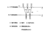
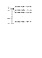
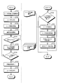
- FIG. 1 is a diagram showing a flow of operation in the synchronous reading method of the laser and the camera.
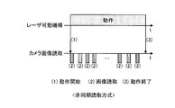
- FIG. 2 is a diagram showing a flow of operation of the laser and camera in the asynchronous reading method.
- the operation process of the laser movable mechanism can be continued without being interrupted as in the synchronous reading method in FIG.
- the image reading process of the camera can be appropriately executed while the operation process of the laser movable mechanism is continued.
- the asynchronous reading method of FIG. 2 eliminates the need for communication processing to synchronize the operation of the laser movable mechanism and the camera as shown in FIG. 1, and can keep the operating speed of the laser movable mechanism constant. The scan time can be shortened, and the cost can be reduced.
- the present invention has been made in view of the above, and in the case of detecting the three-dimensional shape of an object by an asynchronous reading method using a laser and a camera, it is possible to improve the accuracy at the time of detecting the three-dimensional shape.
- An object of the present invention is to propose an object height estimation device and an image reading device.
- the object height estimation device includes a placement surface on which the object whose height is to be estimated, and the placement surface described above.
- a linear light irradiating unit that irradiates linear light parallel to one direction; an actuator for linear light that moves the linear light in a second direction orthogonal to the first direction on the placement surface; and the target.
- An identification area that is adjacent to the object area on which the object is placed in the first direction and is irradiated with a part of the linear light in a state where the object is placed on the object area;
- An imaging camera for linear light that continuously captures at least the object area and the identification area asynchronously with the movement of the linear light in the second direction in a state including the linear light; and The linear light irradiated on the object is imaged by the linear light imaging camera.
- a height estimation unit that estimates height information of the object based on each linear optical imaging data, and the height estimation unit corresponds to the identification area in the linear optical imaging data Based on the position of the linear light in the region, the linear light current position including at least the position in the second direction of the linear light, and at least the position in the second direction among the regions corresponding to the identification area
- a parameter based on the positional relationship between the linear light irradiating unit and the linear light imaging camera that are set in advance at a plurality of linear light reference positions, and the linear light in the object area. From the shape, height information of the object at the current position of the linear light is estimated.
- an image reading apparatus includes at least the object height estimation apparatus described above and an imaging line parallel to the first direction.
- An object imaging device that images a part of the object area, an object actuator that moves the imaging line in the second direction, and the object while moving the imaging line in the second direction.
- An image processing unit that corrects object image data generated by continuously capturing images based on height information of the object estimated by the height estimation unit.
- An object height estimation apparatus and an image reading apparatus detect a three-dimensional shape of an object by an asynchronous reading method using a laser (linear light irradiation unit) and a camera (an imaging camera for linear light). In this case, there is an effect that the accuracy at the time of detecting the three-dimensional shape can be improved.
- FIG. 1 is a diagram showing a flow of operation in a synchronous reading system of a laser and a camera.
- FIG. 2 is a diagram showing a flow of operations in the asynchronous reading method of the laser and the camera.
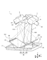
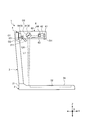
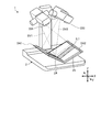
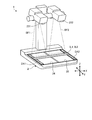
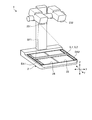
- FIG. 3 is a perspective view of the image reading apparatus including the object height estimation apparatus according to the embodiment in a horizontal state.
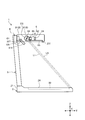
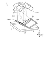
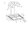
- FIG. 4 is a perspective view of the image reading apparatus according to the embodiment in an inclined state.
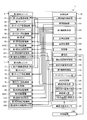
- FIG. 5 is a block diagram of the image reading apparatus according to the embodiment.
- FIG. 6 is a front view of the image reading apparatus according to the embodiment.
- FIG. 7 is a side view of the image reading apparatus according to the embodiment.
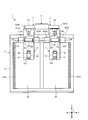
- FIG. 8 is a plan view of the image reading apparatus according to the embodiment.
- FIG. 1 is a diagram showing a flow of operation in a synchronous reading system of a laser and a camera.
- FIG. 2 is a diagram showing a flow of operations in the asynchronous reading method of the laser and the camera.
- FIG. 9 is a flowchart of the operation of the image reading apparatus according to the embodiment.
- FIG. 10 is an explanatory diagram of the operation of the image reading apparatus according to the embodiment.
- FIG. 11 is an explanatory diagram of the operation of the image reading apparatus according to the embodiment.
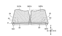
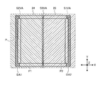
- FIG. 12 is an explanatory diagram of a reading area in the horizontal state of the image reading apparatus according to the embodiment.
- FIG. 13 is an explanatory diagram of a reading area in the horizontal state of the image reading apparatus according to the embodiment.
- FIG. 14 is an explanatory diagram of the operation of the image reading apparatus according to the embodiment.
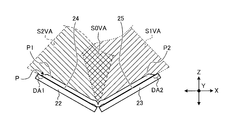
- FIG. 15 is an explanatory diagram of a reading area in an inclined state of the image reading apparatus according to the embodiment.
- FIG. 16 is an explanatory diagram of a reading area in an inclined state of the image reading apparatus according to the embodiment.
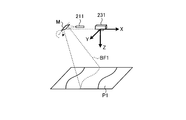
- FIG. 17 is a diagram illustrating a calibration operation performed by the object height estimation apparatus according to the embodiment.
- FIG. 18 is a diagram illustrating parameters corresponding to the linear light reference positions irradiated to the identification area in FIG.
- FIG. 19 is a diagram illustrating an example in which the linear light and the imaging line move with a shift.
- FIG. 20 is a diagram illustrating an example in which the linear light and the imaging line move with a shift.
- FIG. 21 is a diagram illustrating an example in which the linear light and the imaging line move with a shift.
- FIG. 22 is a diagram illustrating an example in which the linear light and the imaging line move with a shift.
- FIG. 23 is a diagram illustrating an example in which the linear light and the imaging line are shifted from each other.
- FIG. 24 is a diagram illustrating an example in which the linear light and the imaging line move with a shift.
- FIG. 25 is a diagram illustrating an example of another embodiment of the identification area.
- FIG. 26 is a diagram illustrating an example of a control form of the linear light irradiation unit.
- FIG. 27 is a diagram illustrating an example of a control form of the linear light irradiation unit.
- FIG. 28 is a diagram illustrating an example of a control form of the linear light irradiation unit.
- FIG. 29 is a flowchart illustrating an example of an imaging process performed by the object height estimation apparatus.
- FIG. 29 is a flowchart illustrating an example of an imaging process performed by the object height estimation apparatus.
- FIG. 30 is a flowchart illustrating an example of multi-thread processing of imaging processing and three-dimensional data calculation processing.
- FIG. 31 is a flowchart illustrating an example of non-multithread processing of imaging processing and three-dimensional data calculation processing.
- FIG. 32 is a diagram illustrating an outline of a method of calculating a three-dimensional coordinate in the embodiment.
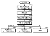
- FIG. 33 is a flowchart illustrating another example of the three-dimensional data calculation process.
- FIG. 34 is a diagram showing an outline of another example of the three-dimensional data calculation process.
- FIG. 35 is a flowchart showing details of another example of the three-dimensional data calculation process.
- FIG. 36 is a diagram for explaining the deformation of the laser light by the rolling shutter.
- FIG. 37 is a diagram for explaining the cause of error due to the rolling shutter.
- FIG. 38 is a diagram for explaining a method for correcting an error caused by the rolling shutter.
- FIG. 39 is a diagram for explaining a method for correcting an error caused by the rolling shutter.
- FIG. 40 is a flowchart showing a laser position estimation flow including a rolling shutter error correction process.
- FIG. 3 is a perspective view of the image reading apparatus including the object height estimation apparatus according to the embodiment in a horizontal state.
- FIG. 4 is a perspective view of the image reading apparatus according to the embodiment in an inclined state.
- FIG. 5 is a block diagram of the image reading apparatus according to the embodiment.
- FIG. 6 is a front view of the image reading apparatus according to the embodiment.
- FIG. 7 is a side view of the image reading apparatus according to the embodiment.
- FIG. 8 is a plan view of the image reading apparatus according to the embodiment.
- FIG. 9 is a flowchart of the operation of the image reading apparatus according to the embodiment.
- FIG. 10 is an explanatory diagram of the operation of the image reading apparatus according to the embodiment.
- FIG. 11 is an explanatory diagram of the operation of the image reading apparatus according to the embodiment.
- FIG. 12 is an explanatory diagram of a reading area in the horizontal state of the image reading apparatus according to the embodiment.
- FIG. 13 is an explanatory diagram of a reading area in the horizontal state of the image reading apparatus according to the embodiment.
- FIG. 14 is an explanatory diagram of the operation of the image reading apparatus according to the embodiment.
- FIG. 15 is an explanatory diagram of a reading area in an inclined state of the image reading apparatus according to the embodiment.
- FIG. 16 is an explanatory diagram of a reading area in an inclined state of the image reading apparatus according to the embodiment.
- FIG. 5 is a functional block diagram illustrating the functions of the image reading apparatus including the object height estimation apparatus according to the embodiment in blocks.
- FIGS. 6 to 8 and FIGS. 10 to 16 schematically show each component for explaining the function of the image reading apparatus according to the embodiment.
- the image reading apparatus 1 is configured by binding a medium as an object in the present embodiment, particularly a plurality of paper media, by a binding unit. While manually turning the binding medium P that is configured, the spread surface of the binding medium P, that is, the first spread surface P1 and the second spread surface P2 are individually read, and each read data corresponding to each spread surface P1, P2. Are combined to generate image data for the double spread surfaces P1 and P2 of the binding medium P, thereby reading the binding medium P.
- the binding medium P is not particularly limited, and is, for example, a book, a magazine, or a document in which a plurality of sheets are bound with staples or clips.
- the same reference numerals in the embodiments are the same components, and the description thereof is omitted or simplified.
- the details of the image reading apparatus 1 according to the embodiment will be described first, and then the object height for estimating the height information of the object used for the correction process of the image data of the object read by the image reading apparatus 1 will be described. Details of the height estimation device 200 will be described. Here, the object height estimation apparatus 200 is included in the image reading apparatus 1.
- the image reading apparatus 1 includes a mounting table 2, an arm 3, a first support unit 4, a second support unit 5, a first reading unit 6, and a second reading unit. 7, illumination 8, rotation mechanism 9, and control device 10.
- the opening direction of the binding medium P is the width direction (X direction)
- the extending direction of the binding portion orthogonal to the opening direction in the horizontal plane is the depth direction (Y direction)
- the width direction and the depth direction is defined as the vertical direction (Z direction).
- the width direction (X direction) may be referred to as a first direction of the placement surface
- the depth direction (Y direction) may be referred to as a second direction orthogonal to the first direction on the placement surface.
- the image reading apparatus 1 according to the present embodiment has a configuration in which a predetermined sheet medium P having a predetermined size and a predetermined thickness is a maximum reading target.
- the mounting table 2 is used for mounting the binding medium P.
- the mounting table main body 21 is a portion that contacts the installation surface of the image reading apparatus 1. As shown in FIG. 12, when the binding medium P is opened, the binding medium P that is opened in the vertical direction is displayed. It is formed in a size that can be placed inside.
- the first mounting unit 22 and the second mounting unit 23 are arranged adjacent to the mounting table main body 21 in the opening direction of the binding medium P, as shown in FIG.
- the first placement unit 22 is formed in a flat plate shape, and a first placement surface 24 is formed facing the first reading unit 6 in the vertical direction.
- the second placement portion 23 is formed in a flat plate shape, and a second placement surface 25 is formed facing the second reading unit 7 in the vertical direction.
- the first placement surface 24 in the present embodiment is a flat surface on which a part of the binding medium P is placed so as to face the first spread surface P1 in the vertical direction. It is.
- the second placement surface 25 in the present embodiment is a flat surface on which a part of the binding medium P is placed so as to face the second spread surface P2 in the vertical direction. That is, the first placement surface 24 and the second placement surface 25 are provided adjacent to each other in the opening direction of the binding medium P.
- the 1st mounting part 22 and the 2nd mounting part 23 are arrange
- the first placement surface 24 and the second placement surface 25 constitute a placement surface on which an object whose height is to be estimated is placed.
- the first placement surface 24 and the second placement surface 25 are respectively identified by the identification area DA1 and the identification used by the object height estimation device 200 described later when estimating the height of the object.
- the area DA2 is included.
- the identification area DA1 and the identification area DA2 are an object area (an area other than the identification areas DA1 and DA2 of the placement surfaces 24 and 25) and a first direction (width direction and X direction) on which the object is placed. Adjacent. As shown in FIG.
- the identification area DA1 set on the first placement surface 24 has a depth direction along the end of the first placement surface 24 on one side in the width direction (left side in FIG. 12). This is a band-like region extending in the area.
- the identification area DA2 set on the second placement surface 25 is a band-like region extending in the depth direction along the end of the second placement surface 25 on the other side in the width direction (right side in FIG. 12). It is.
- the first linear light irradiation unit 211 and the second linear light irradiation unit 212 linear light irradiation unit
- the switching mechanism 26 switches the first placement surface 24 and the second placement surface 25 between a horizontal state and an inclined state. Switching between the horizontal state and the inclined state of the mounting table 2 by the switching mechanism 26 in the present embodiment is performed by the user, that is, manually.
- the switching mechanism 26 includes a rotation support portion 261 and holding mechanisms 262 and 263.
- the rotation support portion 261 includes the first placement portion 22 and the second placement portion based on a rotation axis (not shown) extending in the depth direction at the center of the first placement portion 22 and the second placement portion 23 in the width direction.
- the part 23 is rotated.
- the horizontal state of the mounting table 2 means that the first mounting unit 22 and the second mounting unit 23 are in a horizontal position, that is, the first mounting surface 24 and the first mounting surface.
- a state in which the placement surface 25 is on the same horizontal plane a state in which the angle between the first placement surface 24 and the first placement surface 25 is 180 degrees.
- the inclined state of the mounting table 2 means that the first mounting unit 22 and the second mounting unit 23 are V-shaped in the depth direction, that is, the first mounting surface 24.
- the end on the opposite side of the end of the first mounting surface 25 in the opening direction of the binding medium P is close to the two reading units 6 and 7 (the first mounting surface 24 and State in which the angle formed with the first placement surface 25 is less than 180 degrees).
- the switching mechanism 26 includes a distance of a first perpendicular line drawn from the first rotation axis O1 to the first placement surface 24 in a horizontal state from the first rotation axis O1 and a tilt state of the placement table 2 from the first rotation axis O1.
- the distance of the second perpendicular drawn down on the second placement surface 25 in FIG. 2 is equal, and the distance of the third perpendicular drawn down on the second placement surface 25 in the horizontal state of the placement table 2 from the second rotation axis O2 described later
- the positions of the mounting surfaces 24 and 25 in the inclined state of the mounting table 2 are equal so that the distances of the fourth perpendiculars drawn from the second rotation axis O2 to the first mounting surface 24 in the inclined state of the mounting table 2 are equal.
- the angle formed between the first mounting surface 24 and the first mounting surface 25 in the inclined state of the mounting table 2 may be less than 180 degrees, and preferably 165 degrees, 150 degrees, 135 degrees, and 120 degrees. , 105 degrees, etc. are good.
- the holding mechanisms 262 and 263 maintain the states of the first mounting portion 22 and the second mounting portion 23 in the inclined state of the mounting table 2, respectively, so that the first mounting surface 24 and the second mounting surface 25 are maintained. The inclination is maintained.
- the configuration of the holding mechanisms 262 and 263 is not particularly limited. However, as shown in FIG. 4, the holding mechanisms 262 and 263 may include a hinge mechanism and be accommodated in the mounting table main body 21 in the horizontal state of the mounting table 2. preferable.
- the mounting table detection sensor 27 is a sensor that detects the state of the mounting table 2 as shown in FIG.
- the mounting table detection sensor 27 detects whether the mounting table 2 is in a horizontal state or an inclined state.
- the mounting table detection sensor 27 in the present embodiment detects a change in position of the first mounting surface 24 or the second mounting surface 25 between the horizontal state and the inclined state.
- the mounting table detection sensor 27 is, for example, a switch sensor that detects contact with the first mounting surface 24 or the second mounting surface 25 in a horizontal state and non-contact in an inclined state, or a mounting table in a horizontal state.
- the first mounting surface 24 or the second mounting surface 25 that detects that the inside of the main body portion 21 is dark and the inside of the mounting table main body portion 21 is bright in the inclined state.
- the mounting table detection sensor 27 is connected to the control device 10.
- the arm 3 supports the two reading units 6 and 7 so that the two reading units 6 and 7 are opposed to the mounting table 2 in the vertical direction.
- the arm 3 in the present embodiment has a flat plate shape and is formed so as to extend from the depth side in the depth direction to the upper side in the vertical direction with respect to the two placement surfaces 24 and 25 of the placement table main body 21.
- the first support 4 supports the first reading unit 6 in a rotatable manner.
- the first support portion 4 is formed so as to protrude from the upper portion of the arm 3 in the vertical direction toward one side in the width direction (left side in FIG. 3).
- the first support unit 4 rotatably supports the first reading unit 6 around the first rotation axis O1.
- the second support unit 5 supports the second reading unit 7 in a rotatable manner.
- the second support portion 5 is formed so as to protrude from the upper portion of the arm 3 in the vertical direction toward the other side in the width direction (right side in FIG. 3).
- the second support unit 5 rotatably supports the second reading unit 7 around the second rotation axis O2.
- the first reading unit 6 is disposed so as to face the first mounting surface 24 of the mounting table 2 in the vertical direction. As shown in FIGS. 5 to 8, the first main image reading unit 61, A first carrier 62, a first carrier moving mechanism 63, a first mirror 64, a first mirror rotating mechanism 65, and a lens 66 are provided.
- the first reading unit 6 is formed to extend from the first support portion 4 to the near side in the depth direction.
- the first reading unit 6 rotates around a first rotation axis O1 between a first horizontal position and a first inclined position, which will be described later.
- the first main image reading unit 61 reads a partial region of the binding medium P placed on the placing table 2 as an object imaging device in the present embodiment, and in the first horizontal position in the depth direction.
- it is a linear CCD sensor or CMOS sensor (so-called line sensor) configured by a plurality of image pickup elements (not shown) arranged in the width direction in the width direction.
- the first main image reading unit 61 is connected to the main image reading control unit 101 and the image processing unit 105.
- the first optical axis L ⁇ b> 1 of the first main image reading unit 61 (optical axis toward the mounting table 2) is viewed from the direction orthogonal to the opening direction of the binding medium P, that is, from the depth direction.
- the first reading unit 6 is in the first horizontal position and is parallel to the perpendicular line of the first mounting surface 24 in the horizontal state. Further, the first optical axis L1 of the first main image reading unit 61 (the optical axis toward the mounting table 2) is viewed from the depth direction, as shown in FIG. Thus, it is parallel to the perpendicular of the second mounting surface 25 in the inclined state. Further, as shown in FIG. 6, the first main image reading unit 61 includes the first placement surface 24 in the first horizontal position and the reading region S1F in the horizontal state. That is, as shown in FIGS. 12 and 13, the first main image reading unit 61 reads the first spread surface P1 of the binding medium P formed by the reading region S1F in the first horizontal position and in the horizontal state.
- the first main image reading unit 61 includes the second placement surface 25 in the first inclined position and the reading region S1V in the inclined state. That is, as shown in FIGS. 15 and 16, the first main image reading unit 61 reads the second spread surface P2 of the binding medium P formed by the reading region S1V at the first inclined position and in the inclined state. It is included in the area S1VA.
- the first carrier 62 accommodates the first main image reading unit 61.
- the first carrier 62 in the present embodiment also accommodates a lens 66 disposed on the first optical axis L1.
- the first carrier 62 is supported with respect to the first reading unit 6 so as to be movable in the extending direction of the first optical axis L1, that is, in the depth direction. Accordingly, when the first carrier 62 moves in the depth direction, the position of the first main image reading unit 61 changes, and the optical path length between the first main image reading unit 61 and the first mirror 64 changes.
- the first carrier moving mechanism 63 constitutes an object actuator in the present embodiment, and moves the first carrier 62 supported so as to be movable in the depth direction in the depth direction.
- the first carrier moving mechanism 63 reads the first carrier 62 at a reading start position (see FIG. 7) and a position in the depth direction from the reading start position, that is, the first main image reading unit 61 and the first mirror 64. Is moved back and forth between the reading end position (see FIG. 11) at which the optical path length between the two ends becomes shorter.
- the first carrier moving mechanism 63 has an actuator (not shown), and reciprocates the first carrier 62 by the driving force from the actuator.
- the actuator constitutes an object actuator in the present embodiment.
- the first carrier moving mechanism 63 is connected to the first mechanism control unit 103.
- the first mirror 64 changes the direction of the first optical axis L ⁇ b> 1 of the first main image reading unit 61 and is supported rotatably with respect to the first reading unit 6.
- the first mirror 64 in the present embodiment is supported around a third rotation axis O3 parallel to the opening direction of the binding medium P at the first horizontal position.
- the first mirror 64 is located behind the first main image reading unit 61 in the depth direction.
- the first mirror 64 is disposed on the far side in the depth direction with respect to the binding medium P (the placement surfaces 24 and 25) placed on the placement table 2 in the width direction view.
- the first mirror 64 folds the first optical axis L1 in the depth direction on the third rotation axis O3 on the lower side in the vertical direction and on the near side in the depth direction than the first mirror 64 in the width direction view.
- the first mirror 64 moves the first optical axis L1 in the direction perpendicular to the opening direction of the binding medium P, that is, in the depth direction, by rotating around the third rotation axis O3.
- the first mirror rotating mechanism 65 constitutes an object actuator in the present embodiment, and rotates the first mirror 64 that is rotatably supported around the third rotation axis O3.
- the first mirror rotating mechanism 65 binds the first mirror 64 to the reading start position (see FIG. 7) where the first optical axis L1 is located behind the end of the binding medium P in the depth direction.
- the medium P is rotated between a reading end position (see FIG. 11) positioned on the near side of the front side end in the depth direction of the medium P.
- the optical path length between the first mirror 64 and the mounting surfaces 24 and 25 becomes longer than the reading start position.
- the first mirror rotating mechanism 65 has an actuator (not shown), and rotates the first mirror 64 by a driving force from the actuator.
- the actuator constitutes an object actuator in the present embodiment.
- the first mirror rotation mechanism 65 is connected to the first mechanism control unit 103.
- the second reading unit 7 is arranged to face the second mounting surface 25 of the mounting table 2 in the vertical direction, and has the same configuration as the first reading unit 6 as shown in FIGS. And a second main image reading unit 71, a second carrier 72, a second carrier moving mechanism 73, a second mirror 74, a second mirror rotating mechanism 75, and a lens 76.
- the second reading unit 7 is formed to extend from the second support portion 5 to the near side in the depth direction.
- the second reading unit 7 rotates around the second rotation axis O2 between a second horizontal position and a second inclined position, which will be described later.
- the second main image reading unit 71 reads a partial region of the binding medium P placed on the placing table 2 as an object imaging device in the present embodiment, and in the second horizontal position, in the depth direction.
- it is a linear CCD sensor or CMOS sensor (so-called line sensor) configured by a plurality of image pickup elements (not shown) arranged in the width direction in the width direction.
- the second main image reading unit 71 is connected to the main image reading control unit 101 and the image processing unit 105 as shown in FIG.
- the second optical axis L2 of the second main image reading unit 71 (the optical axis toward the mounting table 2) is viewed from the direction perpendicular to the opening direction of the binding medium P, that is, from the depth direction.
- the second optical axis L2 of the second main image reading unit 71 (the optical axis toward the mounting table 2) is viewed from the depth direction, as shown in FIG. Thus, it is parallel to the perpendicular of the first mounting surface 24 in the inclined state.
- the second main image reading unit 71 is in the second horizontal position, and the reading region S ⁇ b> 2 ⁇ / b> F in the horizontal state includes the second placement surface 25. That is, as shown in FIGS. 12 and 13, the second main image reading unit 71 reads the second spread surface P2 of the binding medium P formed by the reading region S2F in the second horizontal position and in the horizontal state.
- the second main image reading unit 71 includes the first placement surface 24 in the second inclined position and the reading region S ⁇ b> 2 ⁇ / b> V in the inclined state. That is, as shown in FIGS. 15 and 16, the second main image reading unit 71 reads the first spread surface P1 of the binding medium P formed by the reading region S2V in the second inclined position and in the inclined state. It is included in the area S2VA.
- the reading areas S1F and S1V of the first main image reading unit 61 and the reading areas S2F and S2V of the second main image reading unit 71 are one reading area S1F and S1V and the other reading areas S2F and S2V.
- Including a part of The reading area S1F of the first main image reading unit 61 is wider than the first placement surface 24 in the opening direction of the binding medium P as shown in FIG.
- the end portion on the second placement surface 25 side in the width direction of the reading region S1F is located closer to the second placement surface 25 than the center of the first placement portion 22 and the second placement portion 23 in the width direction.
- the reading area S1V of the first main image reading unit 61 is wider than the second placement surface 25 in the opening direction of the binding medium P, as shown in FIG.
- the end portion on the first placement surface 24 side in the width direction of the reading region S1V is located closer to the first placement surface 24 than the center of the first placement portion 22 and the second placement portion 23 in the width direction.
- the reading area S2F of the second main image reading unit 71 is wider than the second placement surface 25 in the opening direction of the binding medium P as shown in FIG.
- An end portion on the first placement surface 24 side in the width direction of the reading region S2F is located closer to the first placement surface 24 side than the center of the first placement portion 22 and the second placement portion 23 in the width direction.
- the reading area S2V of the second main image reading unit 71 is wider than the first placement surface 24 in the opening direction of the binding medium P, as shown in FIG.
- the end portion on the second placement surface 25 side in the width direction of the reading region S2V is located closer to the second placement surface 25 than the center of the first placement portion 22 and the second placement portion 23 in the width direction. Accordingly, since the reading areas S1F and S1V of the first main image reading unit 61 and a part of the reading areas S2F and S2V of the second main image reading unit 71 overlap, they are read and generated by the first main image reading unit 61.
- the first read data and the second read data generated by being read by the second main image reading unit 71 include read data that overlap each other.
- the second carrier 72 houses the second main image reading unit 71.
- the second carrier 72 in the present embodiment also accommodates a lens 76 disposed on the second optical axis L2.
- the second carrier 72 is supported by the second reading unit 7 so as to be movable in the extending direction of the second optical axis L2, that is, in the depth direction. Accordingly, when the second carrier 72 moves in the depth direction, the position of the second main image reading unit 71 changes, and the optical path length between the second main image reading unit 71 and the second mirror 74 changes.
- the second carrier moving mechanism 73 constitutes an object actuator in the present embodiment, and moves the second carrier 72 supported so as to be movable in the depth direction in the depth direction.
- the second carrier moving mechanism 73 reads the second carrier 72 at the reading start position and the position in the depth direction from the reading start position, that is, the optical path between the second main image reading unit 71 and the second mirror 74. It is reciprocated between the reading end position where the length becomes shorter.
- the second carrier moving mechanism 73 has an actuator (not shown), and reciprocates the second carrier 72 by a driving force from the actuator.
- the actuator constitutes an object actuator in the present embodiment.
- the second carrier moving mechanism 73 is connected to the first mechanism control unit 103 as shown in FIG.
- the second mirror 74 changes the direction of the first optical axis L ⁇ b> 2 of the second main image reading unit 71 and is supported rotatably with respect to the second reading unit 7. .
- the second mirror 74 in the present embodiment is supported around the fourth rotation axis O4 parallel to the opening direction of the binding medium P at the second horizontal position.
- the second mirror 74 is located behind the second main image reading unit 71 in the depth direction.
- the second mirror 74 is arranged on the far side in the depth direction from the binding medium P (the placement surfaces 24 and 25) placed on the placement table 2 in the width direction view.
- the second mirror 74 folds the second optical axis L2 in the depth direction on the lower side in the vertical direction on the fourth rotation axis O4 and closer to the near side in the depth direction than the second mirror 74 when viewed in the width direction.
- the second mirror 74 is configured to move the second optical axis L2 in the direction perpendicular to the opening direction of the binding medium P, that is, in the depth direction by rotating around the fourth rotation axis O4.
- the second mirror rotating mechanism 75 constitutes the object actuator in the present embodiment, and rotates the second mirror 74 that is rotatably supported around the fourth rotation axis O4.
- the second mirror rotating mechanism 75 causes the second mirror 74 to move the second optical axis L2 to the reading start position where the second optical axis L2 is located on the inner side of the binding medium P in the depth direction and the depth direction of the binding medium P. Is rotated between the reading end position located on the near side with respect to the end portion on the near side.
- the optical path length between the second mirror 74 and the mounting surfaces 24 and 25 becomes longer than the reading start position.
- the second mirror rotating mechanism 75 has an actuator (not shown), and rotates the second mirror 74 by a driving force from the actuator.
- the actuator constitutes an object actuator in the present embodiment.
- the second mirror rotation mechanism 75 is connected to the first mechanism control unit 103.
- the illumination 8 irradiates the binding medium P placed on the placement table 2 with light.
- the illumination 8 in the present embodiment includes a first illumination 81 provided on the first reading unit 6 side, a second illumination 82 provided on the second reading unit 7 side, and a first illumination.
- a rotation mechanism 83 and a second illumination rotation mechanism 84 are provided.
- the first illumination 81 is supported around the third rotation axis O3.
- the first illumination 81 in the present embodiment is provided at both ends of the first reading unit 6 in the direction of the third rotation axis O3.
- the irradiation range of the pair of first illuminations 81 (imaging line IL1 (see FIG.
- the second illumination 82 is supported around the fourth rotation axis O4.
- the second illumination 82 in the present embodiment is provided at both ends in the direction of the fourth rotation axis O4 with respect to the second reading unit 7.
- the irradiation range of the pair of second illuminations 82 (imaging line IL2 (see FIG. 21 and the like)) is a band extending in the width direction, and is set wider than the reading areas S2F and S2V in the width direction.
- the first illumination 81 and the second illumination 82 are connected to the illumination control unit 102.
- the 1st illumination rotation mechanism 83 comprises the actuator for objects in this embodiment, and rotates a pair of 1st illumination 81 supported rotatably around the 3rd rotating shaft O3.
- the 2nd illumination rotation mechanism 84 comprises the object actuator in this embodiment, and rotates a pair of 2nd illumination 82 supported rotatably around the 4th rotating shaft O4.
- Each illumination rotation mechanism 83, 84 rotates each illumination 81, 82 between a reading start position (see FIG. 7) and a reading end position (see FIG. 11).
- the illumination rotation mechanisms 83 and 84 rotate the optical axes L1 and L2 (reading areas S1F, S1V, S2F, and S2V) that are changed by the mirrors 64 and 74 that rotate between the reading start position and the reading end position.
- Each illumination 81, 82 is rotated so that it is always included in the irradiation area LA of each illumination 81, 82 at the time. That is, the irradiation position with respect to the binding medium P by the illumination 8 changes in synchronization with the position change of the first optical axis L1 and the second optical axis L2 with respect to the binding medium P.
- the first main image reading unit 61 and the second main image reading unit 71 as the imaging device for the object are imaging lines IL1 and IL2 (first first) parallel to the first direction (width direction, X direction).
- the irradiation area of the illumination 81 and the irradiation area of the second illumination 82) image at least a part of the object area (a region other than the identification area on the placement surface).
- Each illumination rotation mechanism 83, 84 in this embodiment is configured such that each illumination 81, 82 rotates at a rotation angle that is twice the rotation angle of each mirror 64, 74.
- Each illumination rotation mechanism 83 and 84 has an actuator (not shown), and rotates each illumination 81 and 82 by a driving force from each actuator.
- the actuator constitutes an object actuator in the present embodiment. That is, in the present embodiment, the object actuator moves the imaging line in the second direction (depth direction, Y direction).
- Each illumination rotation mechanism 83, 84 is connected to the first mechanism control unit 103.
- the rotation mechanism 9 rotates the two reading units 6 and 7, respectively.
- the rotation mechanism 9 in this embodiment includes a first rotation mechanism 91 and a second rotation mechanism 92, as shown in FIGS.
- the first rotation mechanism 91 is provided in the first reading unit 6, and rotates the first reading unit 6 around the first rotation axis O1 between the first horizontal position and the first inclined position. .
- the first rotation mechanism 91 positions the first reading unit 6 at the first horizontal position when the mounting table 2 is in the horizontal state, and puts the first reading unit 6 at the first tilted position when the mounting table 2 is in the inclined state. Position.
- the first rotating mechanism 91 makes the first optical axis L1 parallel to the perpendicular of the first mounting surface 24 in the horizontal state at the first horizontal position, and the second mounting in the inclined state at the first inclined position. It is made parallel to the perpendicular of the mounting surface 25.
- the second rotation mechanism 92 is provided in the second reading unit 7, and rotates the second reading unit 7 around the second rotation axis O2 between the second horizontal position and the second inclined position. .
- the second rotation mechanism 92 positions the second reading unit 7 in the second horizontal position when the mounting table 2 is in the horizontal state, and places the second reading unit 7 in the second inclined position when the mounting table 2 is in the inclined state. Position.
- the second rotation mechanism 92 makes the second optical axis L2 parallel to the perpendicular of the second mounting surface 25 in the horizontal state at the second horizontal position, and the first optical axis L2 in the inclined state at the second inclined position. Parallel to the perpendicular of the mounting surface 24.
- Each rotation mechanism 91 and 92 is connected to the first mechanism control unit 103.
- the 1st linear light irradiation part 211 irradiates the linear light (laser beam) parallel to the 1st direction (width direction, X direction) of the 1st mounting surface 24 as a linear light irradiation part in this embodiment.
- a linear light irradiation part for example, a line laser.
- the first linear light irradiation unit 211 irradiates the first spread surface P1 of the binding medium P placed on the first placement surface 24 with linear light. As shown in FIGS. 7, 8, 10, and 11, the first linear light irradiation unit 211 is rotatably supported with respect to the first reading unit 6.
- the first linear light irradiation unit 211 in this embodiment is supported around a fifth rotation axis O5 parallel to the opening direction of the binding medium P at the first horizontal position.
- the 1st linear light irradiation part 211 in this embodiment is arrange
- the first linear light irradiation unit 211 is located on the far side in the depth direction from the first mirror 64.
- the first linear light irradiation unit 211 is configured to move the linear light in a direction perpendicular to the opening direction of the binding medium P, that is, in the depth direction, by rotating around the fifth rotation axis O5. As shown in FIG. 5, the first linear light irradiation unit 211 is connected to the linear light irradiation control unit 108. In this embodiment, the 1st linear light irradiation part 211 comprises the target object height estimation apparatus 200 of this embodiment.
- the first irradiation unit rotating mechanism 221 constitutes the linear light actuator in the present embodiment, and rotates the first linear light irradiation unit 211 supported rotatably around the fifth rotation axis O5. It is.
- the first irradiation unit rotating mechanism 221 includes the first linear light irradiation unit 211, an irradiation start position where the linear light is located on the back side of the end in the depth direction of the binding medium P, and the binding medium P. Between the irradiation end position located on the near side with respect to the near end portion in the depth direction.
- the 1st irradiation part rotation mechanism 221 has an actuator which is not illustrated, and rotates the 1st linear light irradiation part 211 with the driving force from an actuator.
- the actuator constitutes the linear light actuator in the present embodiment.
- the first irradiation unit rotation mechanism 221 is connected to the second mechanism control unit 110.
- the 1st irradiation part rotation mechanism 221 comprises the target object height estimation apparatus 200 of this embodiment.
- the first linear light imaging camera 231 is a linear light imaging camera in the present embodiment, and includes at least the object area and the identification area DA1 in the second direction (depth) of linear light in a state including linear light. (Image direction, Y direction) is taken continuously and asynchronously.
- the first linear light imaging camera 231 has a plurality of imaging elements (not shown) arranged in the width direction when viewed in the depth direction at a first horizontal position, and a plurality of illustrations arranged in the depth direction.
- a rectangular CCD sensor or a CMOS sensor so-called area sensor configured by an imaging device that does not perform the above operation. As shown in FIGS.
- the first linear light imaging camera 231 is located in the vicinity of the end portion on the near side in the depth direction of the first reading unit 6.
- the first spread surface P ⁇ b> 1 of the binding medium P on the placement surface 24 is formed so as to protrude from the lower side of the first reading unit 6 toward the first placement surface 24 so that it can be imaged.
- the first linear light imaging camera 231 is connected to the linear light imaging control unit 109 and the height estimation unit 130.
- the first linear light imaging camera 231 constitutes the object height estimation apparatus 200 of the present embodiment.
- the 2nd linear light irradiation part 212 irradiates the linear light parallel to the 1st direction (width direction, X direction) of the 2nd mounting surface 25 as a linear light irradiation part in this embodiment.
- a linear light irradiation part for example, a line laser.
- the second linear light irradiation unit 212 irradiates the second spread surface P2 of the binding medium P placed on the second placement surface 25 with linear light.
- the second linear light irradiation unit 212 is rotatably supported with respect to the second reading unit 7.
- the second linear light irradiation unit 212 in the present embodiment is supported around the sixth rotation axis O6 parallel to the opening direction of the binding medium P at the second horizontal position.
- the 2nd linear light irradiation part 212 in this embodiment is arrange
- the second linear light irradiation unit 212 is located on the far side in the depth direction with respect to the second mirror 74.
- the second linear light irradiating unit 212 converts linear light in the depth direction in the depth direction more than the second linear light irradiating unit 212 on the sixth rotation axis O6 in the lower side in the vertical direction and in the width direction. Fold it forward.
- the second linear light irradiation unit 212 is configured to move the linear light in a direction orthogonal to the opening direction of the binding medium P, that is, in the depth direction by rotating around the sixth rotation axis O6. As shown in FIG. 5, the second linear light irradiation unit 212 is connected to the linear light irradiation control unit 108. In this embodiment, the 2nd linear light irradiation part 212 comprises the target object height estimation apparatus 200 of this embodiment.
- the second irradiation unit rotating mechanism 222 constitutes the linear light actuator in the present embodiment, and rotates the second linear light irradiation unit 212 supported rotatably around the sixth rotation axis O6. It is.
- the second irradiation unit rotating mechanism 222 moves the second linear light irradiation unit 212 to an irradiation start position where the linear light is located on the back side of the end in the depth direction of the binding medium P, and the binding medium P. Between the irradiation end position located on the near side with respect to the near end portion in the depth direction.
- the second irradiation unit rotating mechanism 222 has an actuator (not shown), and rotates the second linear light irradiation unit 212 by the driving force from the actuator.
- the actuator constitutes the linear light actuator in the present embodiment.
- the second irradiation unit rotation mechanism 222 is connected to the second mechanism control unit 110.
- the 2nd irradiation part rotation mechanism 222 comprises the target object height estimation apparatus 200 of this embodiment.
- the second linear light imaging camera 232 is a linear light imaging camera in the present embodiment, and includes at least the target area and the identification area DA2 in the second direction (depth) of linear light in a state including linear light. (Image direction, Y direction) is taken continuously and asynchronously.
- the second linear light imaging camera 232 has a plurality of imaging elements (not shown) arranged in the width direction when viewed in the depth direction at the second horizontal position, and a plurality of illustrations arranged in the depth direction.
- a rectangular CCD sensor or a CMOS sensor so-called area sensor configured by an imaging device that does not perform the above operation. As shown in FIGS.
- the second linear light imaging camera 232 is located near the end of the second reading unit 7 on the near side in the depth direction, and is on the second placement surface 25.
- the second spread surface P ⁇ b> 2 of the binding medium P is formed so as to protrude from the lower side of the second reading unit 7 toward the second placement surface 25 so that an image can be taken.
- the second linear light imaging camera 232 is connected to the linear light imaging control unit 109 and the height estimation unit 130.
- the second linear light imaging camera 232 constitutes the object height estimation apparatus 200 of the present embodiment.
- the control device 10 controls the image reading device 1 and rotates the reading units 6 and 7 between the horizontal position and the inclined position in accordance with the switching of the mounting table 2 between the horizontal state and the inclined state. Controls rotational movement. Further, the control device 10 controls the movement operation of the carriers 62 and 72, the rotation operation of the mirrors 64 and 74, and the rotation operation of the illuminations 81 and 82, and the binding medium P by the main image reading units 61 and 71. The imaging operation is controlled. Furthermore, the control device 10 controls at least the rotation operation of each of the linear light irradiation units 211 and 212, and includes at least the object area and the identification areas DA1 and DA2 in the second direction of the linear light while including the linear light. The imaging operation of each of the linear light imaging cameras 231 and 232, which continuously capture images asynchronously with the movement in the depth direction and the Y direction, is controlled.
- the control device 10 includes a main image reading control unit 101, an illumination control unit 102, a first mechanism control unit 103, a device control unit 104, an image processing unit 105, and a storage unit 106.
- the communication unit 107, the linear light irradiation control unit 108, the linear light imaging control unit 109, the second mechanism control unit 110, the calibration unit 120, and the height estimation unit 130 are provided as functions.
- the main image reading control unit 101, the illumination control unit 102, the first mechanism control unit 103, the device control unit 104, the image processing unit 105, the storage unit 106, and the communication unit 107 constitute the image reading apparatus 1 in the present embodiment.
- the height estimation unit 130 constitutes the object height estimation apparatus 200 in the present embodiment.
- the height estimation unit 130 further includes a linear light detection unit 131, a linear light position extraction unit 132, an error correction unit 133, and a three-dimensional coordinate calculation unit 134 as functions.
- the hardware configuration of the control device 10 mainly includes a CPU (Central Processing Unit) that performs arithmetic processing, a memory (RAM, ROM) that stores programs and information, an input / output interface, and the like, and is a known personal computer or scanner device. Therefore, detailed description is omitted.
- CPU Central Processing Unit
- the main image reading control unit 101 controls the imaging operation of the main image reading units 61 and 71.
- the main image reading control unit 101 controls imaging start / end timing, exposure time, exposure timing, and the like of each of the main image reading units 61 and 71.
- the main image reading control unit 101 in the present embodiment controls at least the imaging start / end timing in synchronization among the imaging operations of the main image reading units 61 and 71.
- the illumination control unit 102 controls the blinking operation of each illumination 81 and 82.
- the illumination control unit 102 controls lighting / extinguishing timing of each of the lights 81 and 82, a light amount, and the like.
- the illumination control part 102 in this embodiment controls synchronously at least lighting / extinguishing timing among the blinking operation
- the first mechanism control unit 103 constitutes an object actuator in the present embodiment.
- Each carrier moving mechanism 63, 73, each mirror rotating mechanism 65, 75, each illumination rotating mechanism 83, 84, The rotating mechanisms 91 and 92 are controlled.
- the first mechanism control unit 103 operates the actuator of each mechanism, moves each carrier 62, 72, rotates each mirror 64, 74, rotates each illumination 81, 82, and each reading unit 6, 7 Controls rotational movement.
- the 1st mechanism control part 103 in this embodiment synchronizes the movement operation of each carrier 62 and 72 mutually, the rotation operation of each mirror 64 and 74 mutually synchronizes, and the rotation operation of each illumination 81 and 82 Are synchronized with each other, and the rotation operations of the reading units 6 and 7 are controlled in synchronization with each other.
- the first mechanism control unit 103 synchronizes the movement operation of the first carrier 62, the rotation operation of the first mirror 64, and the rotation operation of the first illumination 81, and the movement operation of the second carrier 72 and the second mirror 74.
- the rotation operation and the rotation operation of the second illumination 82 are synchronized.
- the device control unit 104 outputs instructions to the control units 101 to 103 and 105 to 130 based on the user's reading instructions, and causes the image reading apparatus 1 to perform each operation.
- the apparatus control unit 104 also determines the state of the image reading apparatus 1 with a sensor (not shown) and notifies the outside of a failure of the image reading apparatus 1 and the like.
- the image reading apparatus 1 in the present embodiment is provided with a scan button (not shown) that is exposed to the outside, although not shown.
- the scan button is connected to the control device 10 and outputs a scan button ON signal when pressed, and gives a reading instruction to the device control unit 104.
- the scan button is not particularly limited as long as it outputs a scan button ON signal when operated by a user.
- a mechanical push button for example, a mechanical push button, a capacitive touch button, an optical touch button, etc. Any of these may be used.
- a scan button ON signal may be output to the control device 10 from the external device 300 connected to the control device 10 instead of the scan button.
- the apparatus control unit 104 when scanning the object, the apparatus control unit 104 outputs instructions to the control units 106 and 108 to 130 of the object height estimation apparatus 200 so as to estimate the height information of the object.
- the object height estimation apparatus 200 may perform each operation.
- the image processing unit 105 generates first read data corresponding to a part of the binding medium P based on the first imaging signal output from the first main image reading unit 61, and the second main image reading unit 71 Based on the output second imaging signal, second read data corresponding to a part of the binding medium P is generated.
- the image processing unit 105 generates image data corresponding to the binding medium P by combining the generated first read data and second read data.
- the first read data and the second read data include read data that overlap each other, the first read data and the second read data are based on the overlapping areas of the first read data and the second read data.
- One of the read data and the other read data excluding the overlapping region are combined to generate image data.
- the image processing unit 105 also corrects and crops the first read data and the second read data, or the image data.
- the image processing unit 105 serves as a coordinate relationship calculation unit that associates the three-dimensional coordinates based on the height information estimated by the height estimation unit 130 with the two-dimensional coordinates of the generated image data. It also has a function.
- the image processing unit 105 performs image processing such as distortion correction on the object based on the calculation result by the coordinate relationship calculation unit. That is, in the present embodiment, the image processing unit 105 generates an object image generated by continuously imaging an object while moving the imaging lines IL1 and IL2 in the second direction (depth direction, Y direction). The data is corrected based on the height information of the object estimated by the height estimation unit 130 described later.
- the storage unit 106 stores the generated first read data, second read data, and image data.
- the image processing unit 105 stores parameters used in height estimation processing obtained by the calibration unit 130 described later.
- the communication unit 107 connects the image reading apparatus 1 and the external device 300.
- the communication unit 107 connects to the external device 300 by wire such as USB or wirelessly such as Wi-Fi.
- the communication unit 107 can output the first read data, the second read data, and the image data stored in the storage unit 106 to the connected external device 300.
- the external device 300 is not particularly limited, and includes a mobile terminal such as a smartphone, a mobile phone, a tablet, and a notebook PC, a desktop PC, and a server.
- the image reading apparatus 1 may function as a network scanner by being connected to the outside by the communication unit 107.
- the linear light irradiation control unit 108 controls the blinking operation of each of the linear light irradiation units 211 and 212.
- the linear light irradiation control unit 108 controls lighting / extinguishing timings, light amounts, and the like of the linear light irradiation units 211 and 212.
- the linear light irradiation control part 108 in this embodiment controls at least the lighting / extinguishing timing in synchronization among the blinking operations of the linear light irradiation parts 211 and 212.
- the linear light imaging control unit 109 controls the imaging operation of the linear light imaging cameras 231 and 232.
- the linear light imaging control unit 109 controls the imaging start / end timing, exposure time, exposure timing, and the like of each of the linear light imaging cameras 231 and 232.
- the linear light imaging control unit 109 in this embodiment controls at least the imaging start / end timing in synchronization among the imaging operations of the linear light imaging cameras 231 and 232.
- the second mechanism control unit 110 constitutes the linear light actuator in the present embodiment, and controls the irradiation unit rotating mechanisms 221 and 222.
- the second mechanism control unit 110 operates the actuators of the irradiation unit rotation mechanisms 221 and 222 to control the rotation operation of the linear light irradiation units 211 and 212.
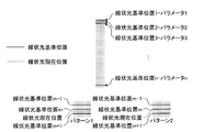
- the calibration unit 120 includes a plurality of linear light reference positions (see FIGS. 17 and 18) including at least positions in the second direction (depth direction and Y direction) among the areas corresponding to the identification areas DA1 and DA2. Parameters based on the positional relationship between the linear light irradiation units 211 and 212 and the linear light imaging cameras 231 and 232 are respectively set in advance.
- FIG. 17 is a diagram illustrating a calibration operation performed by the object height estimation apparatus according to the embodiment.
- the second linear light irradiation unit 212 mounted on the second reading unit 7 is directed from the back side in the depth direction to the near side on the second placement surface 25 including the identification area DA2.
- FIG. 18 is a diagram illustrating parameters corresponding to the linear light reference positions irradiated to the identification area in FIG.
- the parameter 1 for three-dimensional coordinate calculation is set with respect to the linear light reference position 1 indicated by the linear light B1 irradiated to the identification area DA2.
- parameters 2, 3 to n for three-dimensional coordinate calculation are respectively set for the linear light reference positions 2, 3 to n indicated by the respective linear lights B2, B3 to Bn.
- the setting method of the parameters 1, 2, 3 to n for calculating the three-dimensional coordinates is based on the known triangulation based on the positional relationship between the linear light irradiation units 211 and 212 and the linear light imaging cameras 231 and 232.
- the distance method shall be used.
- the calibration unit 120 stores these parameters 1, 2, 3 to n in the storage unit 106 in association with the linear light reference positions 1, 2, 3 to n, respectively.
- the parameters for 3D coordinate calculation stored in the storage unit 106 are coefficients (a, b, c, d) is used (see FIG. 32).
- the height estimation unit 130 estimates the height information of the object based on the respective linear light imaging data obtained by imaging the linear light B irradiated to the object by the linear light imaging cameras 231 and 232. is there.
- the height estimation unit 130 includes at least the second direction of the linear light B based on the position of the linear light B in the region corresponding to each identification area DA1, DA2 in the linear optical imaging data.
- Each of the linear light current position including the position in the depth direction and the Y direction and a plurality of linear light reference positions including at least the position in the second direction among the areas corresponding to the identification areas DA1 and DA2 are set in advance.
- the linear light B the parameters 1, 2, 3 to n (see FIG.
- the height estimation unit 130 determines each of the adjacent linear light reference positions. A parameter is determined based on the parameter.
- the height estimation unit 130 further includes a linear light detection unit 131, a linear light position extraction unit 132, an error correction unit 133, and a three-dimensional coordinate calculation unit 134.
- the linear light detection unit 131 uses the linear light imaging data obtained by imaging the linear light B irradiated to the object by the linear light imaging cameras 231 and 232 to the linear light irradiated to the identification areas DA1 and DA2.
- the light B is detected.
- the linear light position extraction unit 132 is based on at least the second direction of the linear light B based on the position of the linear light B in the area corresponding to each identification area DA1, DA2 detected by the linear light detection unit 131 ( The current position of linear light including the position in the depth direction and the Y direction) is extracted.
- the error correction unit 133 determines a parameter based on the amount of deviation in the second direction between the linear light B in the target area and the linear light B in the actual target area in the linear optical imaging data. Is.
- the three-dimensional coordinate calculation unit 134 includes the linear light current position extracted by the linear light position extraction unit 132, the parameters 1, 2, 3 to n stored in the storage unit 106 by the calibration unit 120 in advance, The height information of the object at the current position of the linear light is estimated from the shape of the object light B in the shape light B. Details of the processing of these height estimation units 130 will be described later.
- the image reading apparatus 1 performs a reading operation on the double spread surfaces P ⁇ b> 1 and P ⁇ b> 2 of the binding medium P placed on the placement table 2.
- the user turns on a power supply (not shown) of the image reading apparatus 1 and supplies power to the image reading apparatus 1 from the outside.
- the user switches the state of the mounting table 2 of the image reading apparatus 1 to a horizontal state or an inclined state.
- the carriers 62 and 72, the mirrors 64 and 74, and the lights 81 and 82 are located at the reading start position.
- the user does not need to perform switching work when the mounting table 2 is in a desired state when the power is turned on.
- the apparatus control unit 104 determines whether or not the mounting table 2 is in a horizontal state (step ST1).
- the apparatus control unit 104 determines whether the mounting table 2 is in a horizontal state or an inclined state based on a detection signal from the mounting table detection sensor 27.
- step ST2 when the apparatus control unit 104 determines that the mounting table 2 is in the horizontal state (Yes in step ST1), the apparatus control unit 104 rotates the reading units 6 and 7 to the horizontal position (step ST2).
- the apparatus control unit 104 controls the rotating mechanisms 91 and 92 by the first mechanism control unit 103 to move the reading units 6 and 7 to the tilted positions. Rotate to horizontal position. If the reading units 6 and 7 are already in the horizontal position before the power is turned on, it is not necessary to rotate the reading units 6 and 7 to the horizontal position.
- the user faces the first mounting surface 24 with the first facing surface P ⁇ b> 1 and the second mounting surface 25 with the second surface.
- the binding medium P is mounted on the mounting table 2 so that the facing surfaces P2 face each other.
- the apparatus control unit 104 determines whether there is a reading instruction (step ST4).
- the apparatus control unit 104 determines whether the scan button is pressed and a scan button ON signal is acquired.
- step ST5 when it is determined that there is a reading instruction (Yes in step ST4), the apparatus control unit 104 starts reading the binding medium P (step ST5).
- the apparatus control unit 104 turns on the lights 81 and 82 at the reading start position by the illumination control unit 102, and reads the binding medium P by the main image reading units 61 and 71 by the main image reading control unit 101.
- device controller 104 determines that there is no reading instruction (No in step ST4), it repeats steps ST1 to ST4 until there is a reading instruction.
- the first mechanism control unit 103 performs mirror rotation control, carrier movement control, and illumination rotation control (step ST6).
- the first mechanism control unit 103 controls the carrier moving mechanisms 63 and 73, the mirror rotating mechanisms 65 and 75, and the illumination rotating mechanisms 83 and 84 in synchronization with each other, as shown in FIGS.
- the carriers 62 and 72, the mirrors 64 and 74, and the lights 81 and 82 at the start position are moved and rotated toward the reading end position shown in FIGS.
- the main image reading units 61 and 71 perform an imaging operation, the reading areas S1F and S2F of the main image reading units 61 and 71 are in a direction orthogonal to the opening direction of the binding medium P, that is, in the depth direction.
- the first main image reading unit 61 continuously reads the first spread surface P1 of the binding medium P in the sub-scanning direction that is the direction from the back side to the near side in the depth direction.
- the second main image reading unit 71 continuously reads the second spread surface P2 of the binding medium P in the sub-scanning direction.
- the rotation of the mirrors 64 and 74 from the reading start position toward the reading end position increases the optical path length between the mirrors 64 and 74 and the placement surfaces 24 and 25, but the carriers 62. , 72 also move from the reading start position toward the reading end position, so that the optical path length between each main image reading unit 61, 71 and each mirror 64, 74 is shortened.
- the first mechanism control unit 103 determines whether or not the reading end position has been reached (step ST7).
- the image processing unit 105 performs image processing on the read data (step ST8).
- the image processing unit 105 generates first read data and second read data.
- the first read data corresponds to a read area S1FA that is an area read by the first main image reading unit 61 from the read start position to the read end position. This corresponds to the image on the first mounting surface 24 side including the first spread surface P1 in the horizontal state of the mounting table 2.
- the second reading data corresponds to the reading area S2FA that is an area read from the reading start position to the reading end position by the second main image reading unit 71, and the second spread data when the mounting table 2 is in the horizontal state. This corresponds to the image on the second placement surface 25 side including the surface P2.
- the image processing unit 105 combines the read data with reference to the overlapping area S0FA with the reading areas S1FA and S2FA, and generates image data corresponding to the image including the binding medium P in the horizontal state of the mounting table 2. .
- the generated image data is corrected and cropped to generate image data (object image data) corresponding to the binding medium P in the horizontal state of the mounting table 2.
- step ST8 the image processing unit 105 performs image processing such as distortion correction on the target object on the target object image data using the height information estimated by the height estimation unit 130.
- the height information used in step ST8 is calculated in step ST34 in FIGS. 30 and 31 to be described later, step ST52 and step ST54 in FIG. 35, and step S72 in FIG.
- step ST7 when it is determined in step ST7 that the first mechanism control unit 103 has not reached the reading end position (No in step ST7), the process returns to step ST7.
- the first mechanism control unit 103 moves and rotates the carriers 62 and 72, the mirrors 64 and 74, and the lights 81 and 82 to the standby position, that is, the reading start position (step). ST9).
- the device control unit 104 outputs image data (step ST10).
- the apparatus control unit 104 outputs image data corresponding to the double spread surfaces P ⁇ b> 1 and P ⁇ b> 2 of the binding medium P read in the horizontal state of the mounting table 2 to the external device 300.
- the apparatus control unit 104 determines that the mounting table 2 is not in a horizontal state (No in step ST1), the apparatus control unit 104 rotates the reading units 6 and 7 to an inclined position (step ST3).
- the apparatus control unit 104 controls the rotation mechanisms 91 and 92 by the first mechanism control unit 103 and sets the reading units 6 and 7 to the horizontal positions. Rotate to tilted position. If the reading units 6 and 7 have already been rotated to an inclined position when the power is turned on in advance, it is not necessary to rotate the reading units 6 and 7 to an inclined position.
- the user faces the first mounting surface 24 with the first facing surface P ⁇ b> 1 and the second mounting surface 25 with the second surface.
- the binding medium P is mounted on the mounting table 2 so that the facing surfaces P2 face each other.
- the generated first read data corresponds to a read area S1VA that is an area read from the read start position to the read end position by the first main image reading unit 61, as shown in FIG. This corresponds to the image on the second mounting surface 25 side including the second spread surface P2 in the inclined state of the mounting table 2.
- the second reading data corresponds to the reading area S2VA that is an area read from the reading start position to the reading end position by the second main image reading unit 71, and is the first spread in the inclined state of the mounting table 2. This corresponds to the image on the first placement surface 24 side including the surface P1.
- the image processing unit 105 combines the read data with reference to the overlapping area S0VA with the reading areas S1VA and S2VA, and generates image data corresponding to the image including the binding medium P in the inclined state of the mounting table 2. .
- the generated image data is corrected and cropped to generate image data corresponding to the binding medium P in the inclined state of the mounting table 2.
- the first main image reading unit 61 and the second main image reading unit 71 are arranged in a horizontal state so that the optical axes L1 and L2 do not intersect with each other. In the read and inclined state, the optical axes L1 and L2 intersect to read the binding medium P. Further, since the distances between the rotary shafts O1 and O2 and the mounting surfaces 24 and 25 are the same even when the mounting table 2 is in a horizontal state or an inclined state, whether the mounting table 2 is in a horizontal state or an inclined state. As a result, it is possible to suppress a change in the optical path length from the reading units 6 and 7 to the binding medium P.
- the binding medium P placed on the mounting table 2 are read, and the first reading unit 6 and the second reading unit 7 are in the same reading state condition in the horizontal state and the inclined state of the mounting table 2. Since the reading area for the binding medium P is switched, the binding medium P can be read with the same image quality in both the horizontal state and the inclined state of the mounting table 2.
- the double spread pages P1 and P2 of the binding medium P are not read by one main image reading unit, the double spread pages P1 and P2 of the binding medium P are read by two main image reading units.
- the binding medium P can be read.
- each spread surface P1, P2 of the binding medium P is read simultaneously, it can be read at a higher speed than when the two spread surfaces P1, P2 are read by one main image reading unit.
- the mirrors 64 and 74 fold back the optical axes L1 and L2 in the depth direction on the lower side in the vertical direction and on the near side in the depth direction than the mirrors 64 and 74 in the width direction.
- the length of 1 in the depth direction can be shortened.
- the inclination state of the mounting table 2 in the embodiment is not limited to one stage, and may be a plurality of stages.
- the tilt positions of the reading units 6 and 7 are set according to the number of stages in the tilt state of the mounting table 2. Accordingly, the control device 10 rotates the reading units 6 and 7 by the rotation mechanism 9 in accordance with the number of steps in the tilted state of the mounting table 2 detected by the mounting table detection sensor 27.
- the switching mechanism 26 in the embodiment may have an actuator (not shown).
- the switching mechanism 26 may switch the horizontal state and the inclined state of the mounting table 2 by the driving force from the actuator. That is, the state of the mounting table 2 may be automatically switched.
- the rotation mechanism 9 rotates the reading units 6 and 7 by a driving force from an actuator (not shown), but the user may manually rotate the reading units 6 and 7.
- the linear light actuator in this embodiment is when the imaging lines IL1 and IL2 are moved in the second direction (depth direction, Y direction).
- the linear light B is moved in the second direction in a state where the linear light B is not included in the imaging lines IL1 and IL2.
- 19 to 24 are diagrams illustrating an example in which the linear light and the imaging line move in a shifted state so as not to overlap each other.
- the linear light BV1 irradiated on the second placement surface 25 from the first linear light irradiation unit 211 is behind the imaging line IL1, that is, It is located behind the imaging line IL1 in the depth direction.
- the linear light BV2 irradiated on the first placement surface 24 from the second linear light irradiation unit 212 is located behind the imaging line IL2, that is, on the far side in the depth direction with respect to the imaging line IL2. ing.
- the linear light BV1 irradiated on the second placement surface 25 from the first linear light irradiation unit 211 is in front of the imaging line IL1. That is, it is located on the near side in the depth direction with respect to the imaging line IL1.
- the linear light BV2 irradiated on the first placement surface 24 from the second linear light irradiation unit 212 is positioned in front of the imaging line IL2, that is, on the near side in the depth direction with respect to the imaging line IL2. ing.
- the linear light BF1 irradiated on the first placement surface 24 from the first linear light irradiation unit 211 is behind the imaging line IL1, That is, it is located on the far side in the depth direction with respect to the imaging line IL1.
- the linear light BF2 irradiated onto the second placement surface 25 from the second linear light irradiation unit 212 is located behind the imaging line IL2, that is, on the far side in the depth direction with respect to the imaging line IL2. ing.
- FIG. 21 in the horizontal state of the image reading apparatus 1
- the linear light BF1 irradiated on the first placement surface 24 from the first linear light irradiation unit 211 is behind the imaging line IL1, That is, it is located on the far side in the depth direction with respect to the imaging line IL1.
- the linear light BF2 irradiated onto the second placement surface 25 from the second linear light irradiation unit 212 is located behind the imaging line IL2, that is, on the far side in the depth
- the linear light BF1 irradiated on the first placement surface 24 from the first linear light irradiation unit 211 is in front of the imaging line IL1, That is, it is located on the near side in the depth direction with respect to the imaging line IL1.
- the linear light BF2 irradiated on the second placement surface 25 from the second linear light irradiation unit 212 is positioned in front of the imaging line IL2, that is, on the near side in the depth direction with respect to the imaging line IL2. ing.
- FIGS. 19 to 22 the example in which the linear light irradiation units 211 and 212 respectively irradiate the mounting surfaces 24 and 25 with the linear light B is shown, but the present invention is not limited thereto.
- a single linear light irradiation unit 211 applies a line to both the mounting surfaces 24 and 25.
- the shaped light B may be irradiated.
- FIG. 23 in the horizontal state of the image reading apparatus 1, the linear light BF1 irradiated on the first placement surface 24 and the second placement surface 25 from the first linear light irradiation unit 211 is imaged.
- the linear light BF1 irradiated on the first mounting surface 24 and the second mounting surface 25 from the first linear light irradiation unit 211 is It is located in front of the imaging line IL1, that is, in front of the imaging lines IL1 and IL2 in the depth direction.
- each linear light B irradiated on the identification areas DA1 and DA2 is not overlapped with the imaging lines IL1 and IL2, and is closer to the front side from the irradiation start position on the far side in the depth direction. Scanning is performed toward the irradiation end position. As a result, the linear light imaging cameras 231 and 232 can satisfactorily capture the linear light B irradiated on the identification areas DA1 and DA2.
- the identification areas DA1 and DA2 do not have to be in the form of strips in the vicinity of the end portions on the placement surfaces 24 and 25 along the depth direction.
- an accessory as a belt-like paperweight for fixing the binding medium P as an object is provided along the depth direction in the vicinity of the ends on the placement surfaces 24 and 25. In this case, these may be substituted for the identification areas DA1 and DA2.
- FIG. 25 is a diagram illustrating an example of another embodiment of the identification area.
- each linear light irradiation unit 211, 212 is controlled by a rotation operation when the object P is irradiated with the linear light B from the irradiation start position toward the irradiation end position.
- the linear light irradiation part 211 irradiates linear light BF1 with respect to the 1st spread surface P1 of the binding medium P as a target object, and targets
- the linear light BF1 may be moved from the far side in the depth direction toward the near side by a rotating operation.
- the linear light BF1 may be moved in a control form as shown in FIG. 26 to 28 are diagrams illustrating an example of a control form of the linear light irradiation unit.
- the first linear light irradiation unit 211 is horizontally moved from the back side in the depth direction toward the front side while maintaining the irradiation angle with respect to the first spread surface P1.
- the linear light BF1 may be moved.
- the first linear light irradiation unit 211 receives the linear light BF1 irradiated toward the mirror M, like the first carrier moving mechanism 63 and the first mirror 64 described above.
- the linear light BF1 may be moved from the back side in the depth direction toward the near side by irradiating the first spread surface P1 via the mirror M and controlling the angle of the mirror M.
- FIG. 29 is a flowchart illustrating an example of an imaging process performed by the object height estimation apparatus 200.
- the linear light may be referred to as laser light.
- the linear light imaging control unit 109 controls the linear light imaging cameras 231 and 232 to estimate the heights placed on the placement surfaces 24 and 25.
- Image data that is, an image without laser light is acquired (step ST20).
- the linear light irradiation control unit 108 controls the linear light irradiation units 211 and 212 to turn on the laser light (step ST21).
- the second mechanism control unit 110 controls the respective irradiation unit rotation mechanisms 221 and 222 to start the rotation operation of each linear light irradiation unit 211, thereby starting the laser operation (step ST22).
- Unit 109 controls each linear light imaging camera 231 and 232 to start reading an image with laser light (step ST23).
- the linear optical imaging control unit 109 determines whether or not the frame is a new frame (step ST24). When it is determined that the frame is a new frame (step ST24 affirmative), the linear optical imaging control unit 109 is mounted on the mounting surfaces 24 and 25.
- the target object P whose height is to be estimated reads image data in a state where the object is irradiated with laser light, that is, an image with laser light (step ST25). On the other hand, when it is determined in step ST24 that the frame is not a new frame (No in step ST24), the process returns to step ST24.
- step ST26 when the linear light irradiation control unit 108 determines that the laser light irradiation has been completed from the irradiation start position to the irradiation end position (step ST26 affirmative), the linear light imaging control unit 109 The image pickup cameras 231 and 232 are controlled, and reading of the image data (image with laser light) in the state irradiated with the laser light is terminated (step ST27).
- step ST27 determines in step ST26 that laser beam irradiation has not ended from the irradiation start position to the irradiation end position (No in step ST26)
- the process returns to step ST24.
- the linear light irradiation control unit 108 controls the linear light irradiation units 211 and 212 to turn off the laser light (step ST28). Thereafter, this process is terminated. In this way, the object height estimation apparatus 200 acquires an image without laser light and an image with laser light as linear optical imaging data.
- FIG. 30 is a flowchart illustrating an example of multi-thread processing of imaging processing and three-dimensional data calculation processing.
- FIG. 31 is a flowchart illustrating an example of non-multithread processing of imaging processing and three-dimensional data calculation processing.
- a thread means an execution unit of parallel processing that is finer than the process in program execution.
- a thread 1 is a thread that performs the imaging process shown in FIG. 29, and a thread 2 is a thread that performs a three-dimensional data calculation process. These thread 1 and thread 2 are processed in parallel in FIG.
- the image without laser light acquired at step ST20 of the thread 1 and the image with laser light acquired at step ST25 of the thread 1 are stored in the storage unit 106 and step ST31 of the thread 2 Is used when detecting laser light.
- the height estimation unit 130 determines whether or not the image processing with laser light has been completed, that is, whether or not reading of the image with laser light has been completed even in one frame in step ST25 of the thread 1 ( Step ST30).
- the linear light detection unit 131 determines the laser beam from the difference between the image without laser light and the image with laser light. Is detected (step ST31).
- the linear light detection unit 131 may detect laser light only from an image with laser light.
- the process returns to step ST30.
- the linear light position extraction unit 132 extracts the laser light position as the linear light current position based on the position of the laser light in the identification areas DA1 and DA2 by the linear light detection unit 131 (step ST32).
- the error correction unit 133 performs error correction in consideration of a rolling shutter caused by the linear light imaging cameras 231 and 232 being so-called line sensors (step ST33). Details of the processing of the error correction unit 133 will be described later with reference to FIGS.
- the three-dimensional coordinate calculation unit 134 includes the linear light current position extracted by the linear light position extraction unit 132 and the parameter 1 stored in the storage unit 106 in advance by the calibration unit 120. , 2, 3 to n and the shape in the object area of the linear light B, the height information of the object at the current position of the linear light is estimated (step ST34).
- FIG. 32 is a diagram illustrating an outline of a method of calculating a three-dimensional coordinate in the embodiment. As shown in FIG. 32, when the linear light detection unit 131 detects laser light from the shape detection camera images as the linear light imaging cameras 231 and 232, the real space shape of the laser light can be acquired.
- the linear light position extraction unit 132 can acquire the laser coordinates (u i , v i ) as the linear light current position in each of the identification areas DA1 and DA2.
- the three-dimensional coordinate calculation unit 134 searches the data in the storage unit 106 in advance for the linear light reference position corresponding to the laser coordinates from the data in the storage unit 106, and matches the linear light current position with the linear light current position.
- the parameters (a, b, c, d) for calculating the appropriate three-dimensional coordinates associated with the are acquired. Then, as shown in FIG. 32, the three-dimensional coordinate calculation unit 134 uses this parameter for a known laser beam plane equation to construct a camera model as shown in FIG. i , Y i , Z i ).
- the calculated three-dimensional coordinates are stored in the storage unit 106 and used as three-dimensional data including the height information of the object P when performing image processing in step ST8 of FIG. 9 described above.
- the process returns to the process of step ST30, and there is laser light read in the next frame until the laser operation of the process of the thread 1 ends and the image reading ends. Similar processing is repeated for the image.
- the processing in FIG. 31 is basically the same except that the thread 1 and thread 2 are processed in parallel in the processing in FIG.
- the imaging process corresponding to the thread 1 in FIG. 30 (the flow on the left side in FIG. 31) is terminated, and all the images without laser light and the images with laser light are acquired, and then correspond to the thread 2 in FIG.
- Three-dimensional data calculation processing (the flow on the right side in FIG. 31) is executed.
- the three-dimensional coordinate calculation unit 134 uses the calibration unit 120 to store the linear light reference position corresponding to the laser coordinates in advance in the storage unit 106.
- the example in which the parameters (a, b, c, d) for calculating the appropriate three-dimensional coordinates associated with the linear light reference position corresponding to the linear light reference position can be obtained by searching from the data has been described.
- the extracted linear light reference position does not necessarily match the linear light reference position stored in the storage unit 106.
- the height estimation unit 130 determines that the linear light current position is a linear light reference position adjacent in the second direction (depth direction, Y direction). If it is between, the parameters are determined based on the respective parameters at the adjacent linear light reference positions.
- FIG. 33 is a flowchart illustrating another example of the three-dimensional data calculation process.
- FIG. 34 is a diagram showing an outline of another example of the three-dimensional data calculation process.
- FIG. 35 is a flowchart showing details of another example of the three-dimensional data calculation process. Note that the processing from step ST40 to step ST42 shown in FIG. 33 is executed in step ST32 in FIGS. Also, the processing from step ST43 to step ST46 shown in FIG. 33 is executed in step ST34 in FIGS.
- the linear light position extraction unit 132 acquires the laser light coordinates in the extracted identification areas DA1 and DA2 (step ST40), and performs linear approximation based on the laser light coordinates (step ST41). )
- the linear light current position is calculated (step ST42).
- the three-dimensional coordinate calculation unit 134 calculates the linear light reference position stored in advance in the storage unit 106 and the calculated linear light current position, as shown in FIG. To which of the pattern 1, pattern 2, or other pattern other than that is determined (step ST43).
- pattern 1 is a pattern in which a linear light current position exists between the linear light reference position m and the linear light reference position m + 1.
- Pattern 2 is a pattern showing a state in which the current position of linear light overlaps the linear light reference position m. If it is determined in step ST43 that the pattern 1 is applicable (step ST43: pattern 1), the three-dimensional coordinate calculation unit 134 outputs the two front and rear laser positions (step ST44). If it is determined in step ST43 that the pattern 2 is applicable (step ST43: pattern 2), the three-dimensional coordinate calculation unit 134 outputs one overlapping laser position (step ST45). In addition, when it is determined in step ST43 that neither the pattern 1 nor the pattern 2 is applicable (step ST43: other), the three-dimensional coordinate calculation unit 134 rejects without outputting this processing result.
- the three-dimensional coordinate calculation unit 134 determines whether the patterns are two laser position patterns, that is, the pattern 1 (step ST50). If it is determined in step ST50 that the pattern is pattern 1 (Yes in step ST50), the three-dimensional coordinate calculation unit 134 calculates the distance between the current laser position and the two laser positions (step ST51). Then, the three-dimensional coordinate calculation unit 134 uses the parameters corresponding to the laser positions stored in the storage unit 106 to calculate two sets of three-dimensional coordinates using the parameters corresponding to the two laser positions. The weighting is added according to the distance between the two laser positions (step ST52). Thereafter, this process is terminated.
- step ST50 determines whether the pattern is one laser position, that is, pattern 2 (step ST53). ).
- step ST53 when it is determined that the pattern 2 is present (Yes in step ST53), the three-dimensional coordinate calculation unit 134 uses the parameter corresponding to the laser position stored in the storage unit 106, and the parameter corresponding to the laser position. Three-dimensional coordinates are calculated (step ST54). Thereafter, this process is terminated.
- step ST54 If it is determined in step ST54 that the pattern is not 2 (No in step ST53), this process is terminated.
- a plurality of imaging elements are arranged at least in the first direction (width direction, X direction), and a plurality of imaging elements in the first direction at the time of imaging. Since the exposure timings of the image sensors are different, a rolling shutter may occur as shown in FIGS. Therefore, in this embodiment, as shown in FIGS. 38 to 40, the exposure interval of each row is calculated, and the process of correcting the three-dimensional data error by predicting the moving position of the laser beam is performed.
- FIG. 36 is a diagram for explaining the deformation of the laser light by the rolling shutter.
- FIG. 37 is a diagram for explaining the cause of error due to the rolling shutter.
- FIG. 38 is a diagram for explaining a method for correcting an error caused by the rolling shutter.
- FIG. 39 is a diagram for explaining a method for correcting an error caused by the rolling shutter.
- FIG. 40 is a flowchart showing a laser position estimation flow including a rolling shutter error correction process.
- the error correction unit 133 of the height estimation unit 130 performs the second direction of the linear light in the target area and the linear light in the actual target area in the linear optical imaging data.
- the parameter is determined based on the amount of deviation in the (depth direction, Y direction). This correction method will be described with reference to FIGS.
- the error correction unit 133 acquires the laser light coordinates in the identification areas DA1 and DA2 from the two-dimensional coordinates of the laser light of the frame m image (step ST60), and performs linear approximation. Te (step ST61), the reference point P b1 (X b1, Y b1 , Z b1) is calculated (step ST62). In addition, the error correction unit 133 acquires the laser beam coordinates in the identification area from the two-dimensional coordinates of the laser beam of the frame m + 1 image (step ST63), performs linear approximation (step ST64), and the reference point P b2 ( X b2, Y b2, Z b2 ) is calculated (step ST65).
- the error correction unit 133 includes a reference point distance d (P b1 , P b ) between the reference point P b1 (X b1 , Y b1 , Z b1 ) and the reference point P b2 (X b2 , Y b2 , Z b2 ). b2 ) is calculated (step ST66).
- the error correction unit 133 estimates the average exposure interval of each row of the frame m image (step ST67), and stores the average exposure interval of each row of the frame m image in the storage unit 106. (Step ST68). Subsequently, the error correction unit 133 uses the laser light coordinates of the nth row of the frame m image and the average exposure interval of each row of the frame m image stored in the storage unit 106 to perform relative exposure of the laser light with respect to the reference point. The interval is calculated (step ST69).
- the object height estimation apparatus 200 and the image reading apparatus 1 include the laser (linear light irradiation units 211 and 212) and the camera (linear light imaging cameras 231 and 232).
- the accuracy at the time of detecting the three-dimensional shape can be improved.
- the present invention is not limited to this and is configured as an area sensor. Also good.
- the first main image reading unit 61 when configured by the area sensor, the first main image reading unit 61 includes a plurality of rows arranged in two or more rows in the width direction when viewed in the depth direction at the first horizontal position.
- the first main image reading unit 61 is configured by the area sensor, the first main image reading unit 61 includes a plurality of rows arranged in two or more rows in the width direction when viewed in the depth direction at the first horizontal position.
- it is a rectangular CCD sensor or a CMOS sensor including an image sensor (not shown) and a plurality of image sensors (not shown) arranged in two or more rows in the depth direction.
- the second main image reading unit 71 when configured by the area sensor, the second main image reading unit 71 includes a plurality of illustrations arranged in two or more rows in the width direction when viewed in the depth direction at the second horizontal position.
- a quadrangular CCD sensor or a CMOS sensor includes an image sensor that is not used and a plurality of image sensors (not shown) that are arranged in two or more rows in the depth direction.
- the mechanism control units 103 and 110 may be common.
- the object actuator and the linear light actuator may be common.
- First linear light imaging camera (linear light imaging camera) 232 Second linear imaging camera (linear imaging camera) 300 External device B, BF1, BF2, BV1, BV2 Linear light DA1, DA2 Identification area IL1, IL2 Imaging line L1 First optical axis L2 Second optical axis LA Irradiation area M Mirror O1 First rotation axis O2 Second rotation axis O3 3rd rotating shaft O4 4th rotating shaft O5 5th rotating shaft O6 6th rotating shaft P Binding medium (object) P1 First facing surface (object) P2 Second facing surface (object) S1F, S1V, S2F, S2V Reading area S1FA, S1VA, S2FA, S2VA Reading area S0FA, S0VA Overlapping area
Landscapes
- Engineering & Computer Science (AREA)
- Multimedia (AREA)
- Signal Processing (AREA)
- Computer Vision & Pattern Recognition (AREA)
- Physics & Mathematics (AREA)
- General Physics & Mathematics (AREA)
- Facsimile Scanning Arrangements (AREA)
- Image Input (AREA)
- Studio Devices (AREA)
- Length Measuring Devices By Optical Means (AREA)
Abstract
高さを推定する対象物が載置される載置面と、載置面の第一方向に平行な線状光を照射する線状光照射部と、線状光を載置面において第一方向と直交する第二方向に移動させる線状光用アクチュエータと、対象物が載置される対象物エリアと第一方向において隣接しており、対象物が対象物エリアに載置された状態において、線状光の一部が照射される識別エリアと、線状光を含んだ状態で、少なくとも対象物エリア及び識別エリアを線状光の第二方向への移動と非同期で連続して撮像する線状光用撮像カメラと、対象物に照射された線状光を線状光用撮像カメラで撮像した各線状光撮像データに基づいて、対象物の高さ情報を推定する高さ推定部と、を備える。高さ推定部は、線状光現在位置と、線状光照射部及び線状光用撮像カメラの位置関係に基づくパラメータと、対象物エリアにおける形状とから、線状光現在位置における対象物の高さ情報を推定する。
Description
本発明は、対象物高さ推定装置及び画像読取装置に関する。
近年、媒体、特に、本や雑誌などの綴じ媒体の電子化の要望がある。このような綴じ媒体の電子化の方法は、綴じ媒体を分離して1枚の媒体にして、通常の画像読取装置で各1枚の画像を読み取る方法と、綴じ媒体を分離せずに、綴じ媒体をめくりながら、綴じ媒体の画像を読み取る方法とがある。後者の場合は、開かれた綴じ媒体を一度に読み取り、綴じ媒体のめくりを手動で行う画像読取装置が提案されている(例えば、特許文献1~4)。
ここで、特許文献1~4等のオーバヘッド型スキャナとして構成された画像読取装置において、電子化の対象物としての綴じ媒体をスキャンする際、対象物のサイズ検出や歪み補正等の画像処理を高精度に行うためには、対象物の3次元形状を高精度に検出することが必要となる。
そこで、従来、3次元形状の検出技術として、特許文献5~7等に記載された各種技術が報告されている。特許文献5及び特許文献6では、レーザとカメラを用いて対象物の3次元形状を検出する技術が開示されている。例えば、特許文献5に記載の技術では、対象物に照射させたレーザ光をカメラで取得し、公知の三角測距方法により対象物の高さを測定している。この他、特許文献7では、赤外線を用いて対象物の3次元形状を検出する技術が開示されている。
ところで、従来技術(特許文献5等)においては、対象物に照射させたレーザ光をカメラで取得し、公知の三角測距方法により対象物の高さを測定することで、対象物の3次元形状を検出しているため、対象物の3次元データを算出するためには、走査中のレーザラインの位置をカメラ側に知らせる必要がある。これを実現するためには、例えば、レーザとカメラの動作を同期させることが考えられるが、この場合には、走査中のレーザラインの位置を正確にカメラの画像読取タイミングと合わせる必要がある。また、ソフトウェアで同期させて実現させる場合にも、適宜レーザを止める必要が生じるため、結果として走査スピードが遅くなる。
このように、レーザとカメラとを同期させて対象物の3次元形状を検出する場合には、図1に示すように、レーザの可動機構の動作処理とカメラの画像読取処理とを、交互に行う必要が生じるため、図1の同期読取方式では、実現コストが大きくなってしまう。ここで、図1は、レーザ及びカメラの同期読取方式での動作の流れを示す図である。
一方、図2に示すように、レーザとカメラとを同期させることなく、レーザとカメラを用いて対象物の3次元形状を検出することも考えられる。ここで、図2は、レーザ及びカメラの非同期読取方式での動作の流れを示す図である。図2の非同期読取方式においては、図1の同期読取方式のようにレーザの可動機構の動作処理を断続させることなく、継続させることができる。そして、レーザの可動機構の動作処理が継続している間に、カメラの画像読取処理を適宜実行することができる。図2の非同期読取方式では、図1に示すようにレーザの可動機構とカメラの動作を同期させるための通信処理が必要なくなり、且つ、レーザの可動機構の動作スピードを一定に保つことができるため、スキャン時間の短縮化を図ることができ、更に低コスト化も実現できる。
しかしながら、図2の非同期読取方式で、レーザとカメラを用いて対象物の3次元形状を検出する場合においても、各種課題が考えられる。例えば、このような非同期読取方式の場合、カメラはレーザの位置を把握できないため、3次元データの計算が困難となり、3次元形状検出時の精度が低くなってしまうという課題がある。
本発明は、上記に鑑みてなされたものであって、レーザとカメラを用いて非同期読取方式にて対象物の3次元形状を検出する場合において、3次元形状検出時の精度を向上させることができる対象物高さ推定装置及び画像読取装置を提案することを目的とする。
上述した課題を解決し、目的を達成するために、本実施形態に係る対象物高さ推定装置は、高さを推定する対象物が載置される載置面と、前記載置面の第一方向に平行な線状光を照射する線状光照射部と、前記線状光を前記載置面において前記第一方向と直交する第二方向に移動させる線状光用アクチュエータと、前記対象物が載置される対象物エリアと前記第一方向において隣接しており、前記対象物が前記対象物エリアに載置された状態において、前記線状光の一部が照射される識別エリアと、前記線状光を含んだ状態で、少なくとも前記対象物エリア及び前記識別エリアを前記線状光の前記第二方向への移動と非同期で連続して撮像する線状光用撮像カメラと、前記対象物に照射された前記線状光を前記線状光用撮像カメラで撮像した各線状光撮像データに基づいて、前記対象物の高さ情報を推定する高さ推定部と、を備え、前記高さ推定部は、前記線状光撮像データのうち、前記識別エリアに対応する領域における前記線状光の位置に基づいた、前記線状光の少なくとも前記第二方向における位置を含む線状光現在位置と、前記識別エリアに対応する領域のうち、少なくとも前記第二方向における位置を含む複数の線状光基準位置において予めそれぞれ設定されている前記線状光照射部及び前記線状光用撮像カメラの位置関係に基づくパラメータと、前記線状光のうち、前記対象物エリアにおける形状とから、前記線状光現在位置における前記対象物の高さ情報を推定する。
また、上述した課題を解決し、目的を達成するために、本実施形態に係る画像読取装置は、上記記載の対象物高さ推定装置と、前記第一方向に平行な撮像ラインによって、少なくとも前記対象物エリアの一部を撮像する対象物用撮像装置と、前記撮像ラインを前記第二方向に移動させる対象物用アクチュエータと、前記撮像ラインを前記第二方向に移動しながら、前記対象物を連続して撮像することで生成された対象物画像データを、前記高さ推定部により推定された前記対象物の高さ情報に基づいて補正する画像処理部と、を備える。
本発明に係る対象物高さ推定装置及び画像読取装置は、レーザ(線状光照射部)とカメラ(線状光用撮像カメラ)を用いて非同期読取方式にて対象物の3次元形状を検出する場合において、3次元形状検出時の精度を向上させることができるという効果を奏する。
以下、本発明につき図面を参照しつつ詳細に説明する。なお、下記の実施形態により本発明が限定されるものではない。また、下記の実施形態における構成要素には、当業者が容易に想定できるものあるいは実質的に同一のものが含まれる。
〔実施形態〕
図3は、実施形態に係る対象物高さ推定装置を含む画像読取装置の水平状態における斜視図である。図4は、実施形態に係る画像読取装置の傾斜状態における斜視図である。図5は、実施形態に係る画像読取装置のブロック図である。図6は、実施形態に係る画像読取装置の正面図である。図7は、実施形態に係る画像読取装置の側面図である。図8は、実施形態に係る画像読取装置の平面図である。図9は、実施形態に係る画像読取装置の動作のフロー図である。図10は、実施形態に係る画像読取装置の動作説明図である。図11は、実施形態に係る画像読取装置の動作説明図である。図12は、実施形態に係る画像読取装置の水平状態における読取領域の説明図である。図13は、実施形態に係る画像読取装置の水平状態における読取領域の説明図である。図14は、実施形態に係る画像読取装置の動作説明図である。図15は、実施形態に係る画像読取装置の傾斜状態における読取領域の説明図である。図16は、実施形態に係る画像読取装置の傾斜状態における読取領域の説明図である。なお、図面において画像読取装置の幅方向はX方向、幅方向と水平面で直交する奥行き方向はY方向、幅方向及び奥行き方向と直交する鉛直方向はZ方向と図示する。図5は、実施形態に係る対象物高さ推定装置を含む画像読取装置が有する機能をブロックで示した機能ブロック図である。図6~図8、図10~図16は、実施形態に係る画像読取装置の機能を説明するため、各構成要素を模式的に図示している。
図3は、実施形態に係る対象物高さ推定装置を含む画像読取装置の水平状態における斜視図である。図4は、実施形態に係る画像読取装置の傾斜状態における斜視図である。図5は、実施形態に係る画像読取装置のブロック図である。図6は、実施形態に係る画像読取装置の正面図である。図7は、実施形態に係る画像読取装置の側面図である。図8は、実施形態に係る画像読取装置の平面図である。図9は、実施形態に係る画像読取装置の動作のフロー図である。図10は、実施形態に係る画像読取装置の動作説明図である。図11は、実施形態に係る画像読取装置の動作説明図である。図12は、実施形態に係る画像読取装置の水平状態における読取領域の説明図である。図13は、実施形態に係る画像読取装置の水平状態における読取領域の説明図である。図14は、実施形態に係る画像読取装置の動作説明図である。図15は、実施形態に係る画像読取装置の傾斜状態における読取領域の説明図である。図16は、実施形態に係る画像読取装置の傾斜状態における読取領域の説明図である。なお、図面において画像読取装置の幅方向はX方向、幅方向と水平面で直交する奥行き方向はY方向、幅方向及び奥行き方向と直交する鉛直方向はZ方向と図示する。図5は、実施形態に係る対象物高さ推定装置を含む画像読取装置が有する機能をブロックで示した機能ブロック図である。図6~図8、図10~図16は、実施形態に係る画像読取装置の機能を説明するため、各構成要素を模式的に図示している。
実施形態に係る画像読取装置1は、図12,図13,図15,図16に示すように、本実施形態における対象物としての媒体、特に複数枚の紙媒体が綴じ部により綴じられることで構成される綴じ媒体Pを手動でめくりながら、綴じ媒体Pの見開きの面、すなわち第1見開き面P1及び第2見開き面P2を個別に読み取り、各見開き面P1,P2にそれぞれ対応する各読取データを合成して、綴じ媒体Pの両見開き面P1,P2に対する画像データを生成することで、綴じ媒体Pを読み取るものである。なお、綴じ媒体Pは、特に限定されるものではないが、例えば、本、雑誌、複数枚の紙をステープルやクリップなどで綴じた書類などである。なお、以下、実施形態における同一符号は、同一の構成要素であるためその説明について省略あるいは簡略化する。
以下、実施形態に係る画像読取装置1の詳細について先に説明し、その後当該画像読取装置1により読取られる対象物の画像データの補正処理に用いられる対象物の高さ情報を推定する対象物高さ推定装置200の詳細について説明する。ここで、対象物高さ推定装置200は、画像読取装置1に含まれるものである。
画像読取装置1は、図3~図5に示すように、載置台2と、アーム3と、第1支持部4と、第2支持部5と、第1読取ユニット6と、第2読取ユニット7と、照明8と、回転機構9と、制御装置10とを備える。なお、画像読取装置1では、綴じ媒体Pの開き方向を幅方向(X方向)、開き方向と水平面視において直交する綴じ部の延在方向を奥行き方向(Y方向)、幅方向と奥行き方向と直交する厚さ方向を鉛直方向(Z方向)とする。ここで、本実施形態において、幅方向(X方向)を載置面の第一方向と呼び、奥行き方向(Y方向)を載置面において第一方向と直交する第二方向と呼ぶことがある。本実施形態における画像読取装置1は、1枚の紙媒体のサイズが所定のサイズであり、厚さが所定の厚さである所定の綴じ媒体Pを最大読取対象とする構成となっている。
載置台2は、綴じ媒体Pを載置するものであり、図4に示す載置台本体部21と、第1載置部22と、第2載置部23と、切替機構26と、図5に示す載置台検出センサ27とを備える。
載置台本体部21は、画像読取装置1の設置面に接触する部分であり、図12に示すように、綴じ媒体Pを開いた際に、鉛直方向視において開かれた状態の綴じ媒体Pを内側に載置できる広さに形成されている。
第1載置部22及び第2載置部23は、図3に示すように、載置台本体部21に対して、綴じ媒体Pの開き方向に隣接して配置されている。第1載置部22は、平板状に形成されており、鉛直方向において第1読取ユニット6と対向して第1載置面24が形成されている。第2載置部23は、平板状に形成されており、鉛直方向において第2読取ユニット7と対向して第2載置面25が形成されている。本実施形態における第1載置面24は、図12に示すように、平坦な面であり、鉛直方向において第1見開き面P1と対向するように綴じ媒体Pの一部が載置されるものである。本実施形態における第2載置面25は、平坦な面であり、鉛直方向において第2見開き面P2と対向するように綴じ媒体Pの一部が載置されるものである。つまり、第1載置面24及び第2載置面25は、綴じ媒体Pの開き方向において隣接して設けられている。
なお、第1載置部22及び第2載置部23は、載置台2の水平状態及び傾斜状態である場合に、隙間を有して載置台2に対して配置されている。従って、綴じ媒体Pが載置台2に載置された状態では、綴じ部をこの隙間に挿入することができる。つまり、綴じ媒体Pの綴じ部は、載置台2において、開かれた状態の綴じ媒体Pの開き方向における両端部よりも、低い位置、すなわち鉛直方向における下側に位置する。従って、開かれた状態の綴じ媒体Pが、隙間の形成されていない載置台2に載置された場合と比較して、綴じ媒体Pのうち、綴じ部の近傍が鉛直方向の上側に盛り上がることを抑制することができ、載置台2に対する綴じ媒体Pの位置ずれを抑制することができる。
本実施形態において、これら第1載置面24及び第2載置面25は、高さを推定する対象物が載置される載置面を構成するものである。また、本実施形態において、これら第1載置面24及び第2載置面25はそれぞれ、後述する対象物高さ推定装置200が対象物の高さを推定する際に用いる識別エリアDA1及び識別エリアDA2を含んで構成される。識別エリアDA1及び識別エリアDA2は、対象物が載置される対象物エリア(各載置面24,25のうち識別エリアDA1,DA2以外の領域)と第一方向(幅方向、X方向)において隣接している。図12に示すように、第1載置面24上に設定された識別エリアDA1は、幅方向の一方側(図12において、左側)の第1載置面24の端部に沿って奥行き方向に延在する帯状の領域である。第2載置面25上に設定された識別エリアDA2は、幅方向の他方側(図12において、右側)の第2載置面25の端部に沿って奥行き方向に延在する帯状の領域である。これら識別エリアDA1,DA2には、対象物が対象物エリアに載置された状態において、後述する第1線状光照射部211及び第2線状光照射部212(線状光照射部)により線状光の一部が照射される。
切替機構26は、第1載置面24及び第2載置面25を水平状態と傾斜状態とに切り替えるものである。本実施形態における切替機構26による載置台2の水平状態と傾斜状態との切り替えは、ユーザーにより、すなわち手動により行われる。切替機構26は、図4に示すように、回転支持部261と、保持機構262,263とを備える。回転支持部261は、幅方向において、第1載置部22及び第2載置部23の中央に奥行き方向に延在する図示しない回転軸を基準に第1載置部22及び第2載置部23を回転させるものである。ここで、載置台2の水平状態とは、図3及び図6に示すように、第1載置部22及び第2載置部23が水平位置、すなわち第1載置面24及び第1載置面25が同一水平面上となる状態(第1載置面24と第1載置面25とのなす角度が180度となる状態)をいう。一方、載置台2の傾斜状態とは、図4及び図14に示すように、第1載置部22及び第2載置部23が奥行き方向視でV字状、すなわち第1載置面24及び第1載置面25の綴じ媒体Pの開き方向において近接する側の端部よりも反対側の端部が2つの読取ユニット6,7に対して近接する状態(第1載置面24と第1載置面25とのなす角度が180度未満となる状態)をいう。
さらに、切替機構26は、後述する第1回転軸O1から載置台2の水平状態における第1載置面24におろした第1垂線の距離と、第1回転軸O1から載置台2の傾斜状態における第2載置面25におろした第2垂線の距離が等しく、且つ、後述する第2回転軸O2から載置台2の水平状態における第2載置面25におろした第3垂線の距離と、第2回転軸O2から載置台2の傾斜状態における第1載置面24におろした第4垂線の距離が等しくなるように、載置台2の傾斜状態における各載置面24,25の位置を設定する。なお、載置台2の傾斜状態における第1載置面24と第1載置面25とのなす角度は、180度未満であればよく、好ましくは、165度、150度、135度、120度、105度などがよい。保持機構262,263は、載置台2の傾斜状態において、第1載置部22及び第2載置部23の状態をそれぞれ維持することで、第1載置面24及び第2載置面25の傾斜を保持するものである。保持機構262,263の構成は、特に限定されるものではないが、図4に示すように、ヒンジ機構を備え、載置台2の水平状態において載置台本体部21の内部に収容されることが好ましい。
載置台検出センサ27は、図5に示すように、載置台2の状態を検出するセンサである。載置台検出センサ27は、載置台2の水平状態であるか、傾斜状態であるかを検出するものである。本実施形態における載置台検出センサ27は、第1載置面24または第2載置面25の水平状態と傾斜状態とにおける位置変化を検出するものである。載置台検出センサ27は、例えば、第1載置面24または第2載置面25に、水平状態で接触し、傾斜状態で非接触となることを検出するスイッチセンサや、水平状態で載置台本体部21の内部が暗くなり、傾斜状態で載置台本体部21の内部が明るくなることを検出する光学センサ、第1載置面24または第2載置面25の水平状態と傾斜状態とにおける鉛直方向における高さの変化を検出する高さセンサなどがある。載置台検出センサ27は、制御装置10に接続されている。
アーム3は、図3及び図4に示すように、2つの読取ユニット6,7を支持することで、2つの読取ユニット6,7を鉛直方向において載置台2に対して対向させるものである。本実施形態におけるアーム3は、平板状であり、載置台本体部21の2つの載置面24,25よりも奥行き方向の奥側から鉛直方向の上側に延在して形成されている。
第1支持部4は、第1読取ユニット6を回転自在に支持するものである。第1支持部4は、アーム3の鉛直方向の上側の部分から、幅方向の一方側(図3において左側)に向かって突出して形成されている。第1支持部4は、第1回転軸O1周りに、第1読取ユニット6を回転自在に支持する。
第2支持部5は、第2読取ユニット7を回転自在に支持するものである。第2支持部5は、アーム3の鉛直方向の上側の部分から、幅方向の他方側(図3において右側)に向かって突出して形成されている。第2支持部5は、第2回転軸O2周りに、第2読取ユニット7を回転自在に支持する。
第1読取ユニット6は、鉛直方向において載置台2の第1載置面24と対向して配置されるものであり、図5~図8に示すように、第1主画像読取部61と、第1キャリア62と、第1キャリア移動機構63と、第1ミラー64、第1ミラー回転機構65と、レンズ66と備える。第1読取ユニット6は、第1支持部4から奥行き方向の手前側に延在して形成されている。第1読取ユニット6は、後述する第1水平位置と第1傾斜位置との間を第1回転軸O1周りに回転するものである。
第1主画像読取部61は、本実施形態における対象物用撮像装置として、載置台2に載置された綴じ媒体Pの一部の領域を読み取るものであり、第1水平位置で、奥行き方向視において幅方向に1列以上配列された複数の図示しない撮像素子により構成された、例えば線状のCCDセンサ又はCMOSセンサ(所謂、ラインセンサ)である。第1主画像読取部61は、図5に示すように、主画像読取制御部101及び画像処理部105に接続されている。第1主画像読取部61の第1光軸L1(載置台2に向かう光軸)は、綴じ媒体Pの開き方向と直交する方向、すなわち奥行き方向から視たに、図6に示すように、第1読取ユニット6が第1水平位置で、水平状態の第1載置面24の垂線と平行である。また、第1主画像読取部61の第1光軸L1(載置台2に向かう光軸)は、奥行き方向から視たに、図14に示すように、第1読取ユニット6が第1傾斜位置で、傾斜状態の第2載置面25の垂線と平行である。また、第1主画像読取部61は、図6に示すように、第1水平位置で、且つ水平状態における読取領域S1Fは、第1載置面24を含む。つまり、第1主画像読取部61は、図12及び図13に示すように、第1水平位置で、且つ水平状態において、綴じ媒体Pの第1見開き面P1を読取領域S1Fにより形成される読取領域S1FAに含む。一方、第1主画像読取部61は、図14に示すように、第1傾斜位置で、且つ傾斜状態における読取領域S1Vは、第2載置面25を含む。つまり、第1主画像読取部61は、図15及び図16に示すように、第1傾斜位置で、且つ傾斜状態において、綴じ媒体Pの第2見開き面P2を読取領域S1Vにより形成される読取領域S1VAに含む。
第1キャリア62は、図6及び図7に示すように、第1主画像読取部61が収容されている。本実施形態における第1キャリア62は、第1光軸L1上に配置されるレンズ66も収容されている。第1キャリア62は、第1読取ユニット6に対して、第1光軸L1の延在方向、すなわち奥行き方向に移動自在に支持されている。従って、第1キャリア62が奥行き方向に移動することで、第1主画像読取部61の位置が変化し、第1主画像読取部61と第1ミラー64との間の光路長が変化する。
第1キャリア移動機構63は、本実施形態における対象物用アクチュエータを構成するものであり、奥行き方向に移動自在に支持された第1キャリア62を奥行き方向に移動させるものである。第1キャリア移動機構63は、第1キャリア62を読取開始位置(図7参照)と、読取開始位置よりも、奥行き方向の奥側の位置、すなわち第1主画像読取部61と第1ミラー64との間の光路長が短くなる読取終了位置(図11参照)との間を往復移動させる。第1キャリア移動機構63は、図示しないアクチュエータを有しており、アクチュエータからの駆動力により第1キャリア62を往復移動させる。本実施形態において、当該アクチュエータは、本実施形態における対象物用アクチュエータを構成するものである。第1キャリア移動機構63は、図5に示すように、第1機構制御部103に接続されている。
第1ミラー64は、図7及び図8に示すように、第1主画像読取部61の第1光軸L1の向きを変更するものであり、第1読取ユニット6に対して回転自在に支持されている。本実施形態における第1ミラー64は、第1水平位置で綴じ媒体Pの開き方向に平行な第3回転軸O3周りに支持されている。第1ミラー64は、第1主画像読取部61よりも奥行き方向における奥側に位置している。本実施形態における第1ミラー64は、幅方向視において載置台2に載置される綴じ媒体P(各載置面24,25)よりも、奥行き方向における奥側に配置されている。第1ミラー64は、奥行き方向の第1光軸L1を、第3回転軸O3において、鉛直方向の下側で、且つ幅方向視において第1ミラー64よりも奥行き方向の手前側に折り返す。また、第1ミラー64は、第3回転軸O3周りに回転することで、綴じ媒体Pの開き方向と直交する方向、すなわち奥行き方向に第1光軸L1を移動させるものである。
第1ミラー回転機構65は、本実施形態における対象物用アクチュエータを構成するものであり、第3回転軸O3周りに回転自在に支持された第1ミラー64を回転させるものである。第1ミラー回転機構65は、第1ミラー64を、第1光軸L1が綴じ媒体Pの奥行き方向の奥側の端部よりも奥側に位置する読取開始位置(図7参照)と、綴じ媒体Pの奥行き方向の手前側の端部よりも手前側に位置する読取終了位置(図11参照)との間を回転させる。ここで、読取終了位置は、読取開始位置よりも、第1ミラー64と各載置面24,25との間の光路長が長くなる。第1ミラー回転機構65は、図示しないアクチュエータを有しており、アクチュエータからの駆動力により第1ミラー64を回転させる。本実施形態において、当該アクチュエータは、本実施形態における対象物用アクチュエータを構成するものである。第1ミラー回転機構65は、第1機構制御部103に接続されている。
第2読取ユニット7は、鉛直方向において載置台2の第2載置面25と対向して配置されるものであり、図5~図8に示すように、第1読取ユニット6と同様の構成であり、第2主画像読取部71と、第2キャリア72と、第2キャリア移動機構73と、第2ミラー74、第2ミラー回転機構75と、レンズ76と備える。第2読取ユニット7は、第2支持部5から奥行き方向の手前側に延在して形成されている。第2読取ユニット7は、後述する第2水平位置と第2傾斜位置との間を第2回転軸O2周りに回転するものである。
第2主画像読取部71は、本実施形態における対象物用撮像装置として、載置台2に載置された綴じ媒体Pの一部の領域を読み取るものであり、第2水平位置で、奥行き方向視において幅方向に1列以上配列された複数の図示しない撮像素子により構成された、例えば線状のCCDセンサ又はCMOSセンサ(所謂、ラインセンサ)である。第2主画像読取部71は、図5に示すように、主画像読取制御部101及び画像処理部105に接続されている。第2主画像読取部71の第2光軸L2(載置台2に向かう光軸)は、綴じ媒体Pの開き方向と直交する方向、すなわち奥行き方向から視たに、第2読取ユニット7が第2水平位置で、水平状態の第2載置面25の垂線と平行である。また、第2主画像読取部71の第2光軸L2(載置台2に向かう光軸)は、奥行き方向から視たに、図14に示すように、第2読取ユニット7が第2傾斜位置で、傾斜状態の第1載置面24の垂線と平行である。また、第2主画像読取部71は、図6に示すように、第2水平位置で、且つ水平状態における読取領域S2Fは、第2載置面25を含む。つまり、第2主画像読取部71は、図12及び図13に示すように、第2水平位置で、且つ水平状態において、綴じ媒体Pの第2見開き面P2を読取領域S2Fにより形成される読取領域S2FAに含む。一方、第2主画像読取部71は、図14に示すように、第2傾斜位置で、且つ傾斜状態における読取領域S2Vは、第1載置面24を含む。つまり、第2主画像読取部71は、図15及び図16に示すように、第2傾斜位置で、且つ傾斜状態において、綴じ媒体Pの第1見開き面P1を読取領域S2Vにより形成される読取領域S2VAに含む。
ここで、第1主画像読取部61の読取領域S1F,S1Vと、第2主画像読取部71の読取領域S2F,S2Vとは、一方の読取領域S1F,S1Vに、他方の読取領域S2F,S2Vの一部を含む。第1主画像読取部61の読取領域S1Fは、図6に示すように、綴じ媒体Pの開き方向において第1載置面24よりも広い。読取領域S1Fの幅方向における第2載置面25側の端部は、幅方向における第1載置部22及び第2載置部23の中央よりも第2載置面25側に位置する。第1主画像読取部61の読取領域S1Vは、図14に示すように、綴じ媒体Pの開き方向において第2載置面25よりも広い。読取領域S1Vの幅方向における第1載置面24側の端部は、幅方向における第1載置部22及び第2載置部23の中央よりも第1載置面24側に位置する。また、第2主画像読取部71の読取領域S2Fは、図6に示すように、綴じ媒体Pの開き方向において第2載置面25よりも広い。読取領域S2Fの幅方向における第1載置面24側の端部は、幅方向における第1載置部22及び第2載置部23の中央よりも第1載置面24側に位置する。第2主画像読取部71の読取領域S2Vは、図14に示すように、綴じ媒体Pの開き方向において第1載置面24よりも広い。読取領域S2Vの幅方向における第2載置面25側の端部は、幅方向における第1載置部22及び第2載置部23の中央よりも第2載置面25側に位置する。従って、第1主画像読取部61の読取領域S1F,S1V及び第2主画像読取部71の読取領域S2F,S2Vの一部が重なるので、第1主画像読取部61により読み取られて生成された第1読取データと、第2主画像読取部71により読み取られて生成された第2読取データとには、互いに重複した読取データが含まれることとなる。
第2キャリア72は、図6及び図7に示すように、第2主画像読取部71が収容されている。本実施形態における第2キャリア72は、第2光軸L2上に配置されるレンズ76も収容されている。第2キャリア72は、第2読取ユニット7に対して、第2光軸L2の延在方向、すなわち奥行き方向に移動自在に支持されている。従って、第2キャリア72が奥行き方向に移動することで、第2主画像読取部71の位置が変化し、第2主画像読取部71と第2ミラー74との間の光路長が変化する。
第2キャリア移動機構73は、本実施形態における対象物用アクチュエータを構成するものであり、奥行き方向に移動自在に支持された第2キャリア72を奥行き方向に移動させるものである。第2キャリア移動機構73は、第2キャリア72を読取開始位置と、読取開始位置よりも、奥行き方向の奥側の位置、すなわち第2主画像読取部71と第2ミラー74との間の光路長が短くなる読取終了位置との間を往復移動させる。第2キャリア移動機構73は、図示しないアクチュエータを有しており、アクチュエータからの駆動力により第2キャリア72を往復移動させる。本実施形態において、当該アクチュエータは、本実施形態における対象物用アクチュエータを構成するものである。第2キャリア移動機構73は、図5に示すように、第1機構制御部103に接続されている。
第2ミラー74は、図8に示すように、第2主画像読取部71の第1光軸L2の向きを変更するものであり、第2読取ユニット7に対して回転自在に支持されている。本実施形態における第2ミラー74は、第2水平位置で綴じ媒体Pの開き方向に平行な第4回転軸O4周りに支持されている。第2ミラー74は、第2主画像読取部71よりも奥行き方向における奥側に位置している。本実施形態における第2ミラー74は、幅方向視において載置台2に載置される綴じ媒体P(各載置面24,25)よりも、奥行き方向における奥側に配置されている。第2ミラー74は、奥行き方向の第2光軸L2を、第4回転軸O4において、鉛直方向の下側で、且つ幅方向視において第2ミラー74よりも奥行き方向の手前側に折り返す。また、第2ミラー74は、第4回転軸O4周りに回転することで、綴じ媒体Pの開き方向と直交する方向、すなわち奥行き方向に第2光軸L2を移動させるものである。
第2ミラー回転機構75は、本実施形態における対象物用アクチュエータを構成するものであり、第4回転軸O4周りに回転自在に支持された第2ミラー74を回転させるものである。第2ミラー回転機構75は、第2ミラー74を、第2光軸L2が綴じ媒体Pの奥行き方向の奥側の端部よりも奥側に位置する読取開始位置と、綴じ媒体Pの奥行き方向の手前側の端部よりも手前側に位置する読取終了位置との間を回転させる。ここで、読取終了位置は、読取開始位置よりも、第2ミラー74と各載置面24,25との間の光路長が長くなる。第2ミラー回転機構75は、図示しないアクチュエータを有しており、アクチュエータからの駆動力により第2ミラー74を回転させる。本実施形態において、当該アクチュエータは、本実施形態における対象物用アクチュエータを構成するものである。第2ミラー回転機構75は、第1機構制御部103に接続されている。
照明8は、載置台2に載置された綴じ媒体Pに光を照射するものである。本実施形態における照明8は、図5~図8に示すように第1読取ユニット6側に設けられる第1照明81と、第2読取ユニット7側に設けられる第2照明82と、第1照明回転機構83と、第2照明回転機構84とを備える。第1照明81は、第3回転軸O3周りに支持されている。本実施形態における第1照明81は、第1読取ユニット6に対して第3回転軸O3方向の両端部に設けられている。一対の第1照明81の照射範囲(撮像ラインIL1(図21等参照))は、幅方向に延在する帯状となり、幅方向において読取領域S1F,S1Vよりも広く設定されている。第2照明82は、第4回転軸O4周りに支持されている。本実施形態における第2照明82は、第2読取ユニット7に対して第4回転軸O4方向の両端部に設けられている。一対の第2照明82の照射範囲(撮像ラインIL2(図21等参照))は、幅方向に延在する帯状となり、幅方向において読取領域S2F,S2Vよりも広く設定されている。第1照明81及び第2照明82は、照明制御部102と接続されている。
第1照明回転機構83は、本実施形態における対象物用アクチュエータを構成するものであり、第3回転軸O3周りに回転自在に支持された一対の第1照明81を回転させるものである。第2照明回転機構84は、本実施形態における対象物用アクチュエータを構成するものであり、第4回転軸O4周りに回転自在に支持された一対の第2照明82を回転させるものである。各照明回転機構83,84は、各照明81,82を読取開始位置(図7参照)と、読取終了位置(図11参照)との間をそれぞれ回転させる。各照明回転機構83,84は、読取開始位置と読取終了位置との間で回転する各ミラー64,74により変化する各光軸L1,L2(読取領域S1F,S1V,S2F,S2V)が、回転時における各照明81,82の照射領域LAに、常に含まれるように各照明81,82を回転させる。つまり、照明8による綴じ媒体Pに対する照射位置は、第1光軸L1及び第2光軸L2の綴じ媒体Pに対する位置変化に同期して変化することとなる。
本実施形態において、対象物用撮像装置としての第1主画像読取部61及び第2主画像読取部71は、第一方向(幅方向、X方向)に平行な撮像ラインIL1,IL2(第1照明81の照射範囲及び第2照明82の照射範囲)によって、少なくとも対象物エリア(載置面のうち識別エリア以外の領域)の一部を撮像する。本実施形態における各照明回転機構83,84は、各ミラー64,74の回転角の2倍の回転角で各照明81,82が回転するように構成されている。各照明回転機構83,84は、図示しないアクチュエータをそれぞれ有しており、各アクチュエータからの駆動力により各照明81,82を回転させる。本実施形態において、当該アクチュエータは、本実施形態における対象物用アクチュエータを構成するものである。つまり、本実施形態において、対象物用アクチュエータは、撮像ラインを第二方向(奥行き方向、Y方向)に移動させる。各照明回転機構83,84は、第1機構制御部103に接続されている。
回転機構9は、2つの読取ユニット6,7をそれぞれ回転させるものである。本実施形態における回転機構9は、図5、図8に示すように、第1回転機構91と、第2回転機構92とを備える。第1回転機構91は、第1読取ユニット6に設けられており、第1読取ユニット6を第1水平位置と第1傾斜位置との間で、第1回転軸O1周りに回転させるものである。第1回転機構91は、載置台2の水平状態であると第1読取ユニット6を第1水平位置に位置させ、載置台2の傾斜状態であると第1読取ユニット6を第1傾斜位置に位置させる。第1回転機構91は、第1水平位置において第1光軸L1を水平状態における第1載置面24の垂線と平行にし、第1傾斜位置において第1光軸L1を傾斜状態における第2載置面25の垂線と平行にする。第2回転機構92は、第2読取ユニット7に設けられており、第2読取ユニット7を第2水平位置と第2傾斜位置との間で、第2回転軸O2周りに回転させるものである。第2回転機構92は、載置台2の水平状態であると第2読取ユニット7を第2水平位置に位置させ、載置台2の傾斜状態であると第2読取ユニット7を第2傾斜位置に位置させる。第2回転機構92は、第2水平位置において第2光軸L2を水平状態における第2載置面25の垂線と平行にし、第2傾斜位置において第2光軸L2を傾斜状態における第1載置面24の垂線と平行にする。各回転機構91,92は、第1機構制御部103に接続されている。
第1線状光照射部211は、本実施形態における線状光照射部として、第1載置面24の第一方向(幅方向、X方向)に平行な線状光(レーザ光)を照射するものであり、例えば、ラインレーザである。本実施形態において、第1線状光照射部211は、第1載置面24に載置された綴じ媒体Pの第1見開き面P1に線状光を照射する。第1線状光照射部211は、図7、図8、図10、図11に示すように、第1読取ユニット6に対して回転自在に支持されている。本実施形態における第1線状光照射部211は、第1水平位置で綴じ媒体Pの開き方向に平行な第5回転軸O5周りに支持されている。本実施形態における第1線状光照射部211は、幅方向視において載置台2に載置される綴じ媒体P(各載置面24,25)よりも、奥行き方向における奥側に配置されている。第1線状光照射部211は、第1ミラー64よりも奥行き方向における奥側に位置している。第1線状光照射部211は、奥行き方向の線状光を、第5回転軸O5において、鉛直方向の下側で、且つ幅方向視において第1線状光照射部211よりも奥行き方向の手前側に折り返す。また、第1線状光照射部211は、第5回転軸O5周りに回転することで、綴じ媒体Pの開き方向と直交する方向、すなわち奥行き方向に線状光を移動させるものである。第1線状光照射部211は、図5に示すように、線状光照射制御部108に接続されている。本実施形態において、第1線状光照射部211は、本実施形態の対象物高さ推定装置200を構成するものである。
第1照射部回転機構221は、本実施形態における線状光用アクチュエータを構成するものであり、第5回転軸O5周りに回転自在に支持された第1線状光照射部211を回転させるものである。第1照射部回転機構221は、第1線状光照射部211を、線状光が綴じ媒体Pの奥行き方向の奥側の端部よりも奥側に位置する照射開始位置と、綴じ媒体Pの奥行き方向の手前側の端部よりも手前側に位置する照射終了位置との間を回転させる。第1照射部回転機構221は、図示しないアクチュエータを有しており、アクチュエータからの駆動力により第1線状光照射部211を回転させる。本実施形態において、当該アクチュエータは、本実施形態における線状光用アクチュエータを構成するものである。第1照射部回転機構221は、第2機構制御部110に接続されている。本実施形態において、第1照射部回転機構221は、本実施形態の対象物高さ推定装置200を構成するものである。
第1線状光用撮像カメラ231は、本実施形態における線状光用撮像カメラとして、線状光を含んだ状態で、少なくとも対象物エリア及び識別エリアDA1を線状光の第二方向(奥行き方向、Y方向)への移動と非同期で連続して撮像するものである。第1線状光用撮像カメラ231は、第1水平位置で、奥行き方向視において幅方向に2列以上配列された複数の図示しない撮像素子と、奥行き方向に2列以上配列された複数の図示しない撮像素子とにより構成された、例えば四角形状のCCDセンサ又はCMOSセンサ(所謂、エリアセンサ)である。第1線状光用撮像カメラ231は、図7、図8、図10、図11に示すように、第1読取ユニット6の奥行き方向の手前側の端部付近に位置しており、第1載置面24上の綴じ媒体Pの第1見開き面P1を撮像可能なように第1読取ユニット6の下側から第1載置面24に向かって突出して形成されている。第1線状光用撮像カメラ231は、図5に示すように、線状光撮像制御部109及び高さ推定部130に接続されている。本実施形態において、第1線状光用撮像カメラ231は、本実施形態の対象物高さ推定装置200を構成するものである。
第2線状光照射部212は、本実施形態における線状光照射部として、第2載置面25の第一方向(幅方向、X方向)に平行な線状光を照射するものであり、例えば、ラインレーザである。本実施形態において、第2線状光照射部212は、第2載置面25に載置された綴じ媒体Pの第2見開き面P2に線状光を照射する。第2線状光照射部212は、図8、図10に示すように、第2読取ユニット7に対して回転自在に支持されている。本実施形態における第2線状光照射部212は、第2水平位置で綴じ媒体Pの開き方向に平行な第6回転軸O6周りに支持されている。本実施形態における第2線状光照射部212は、幅方向視において載置台2に載置される綴じ媒体P(各載置面24,25)よりも、奥行き方向における奥側に配置されている。第2線状光照射部212は、第2ミラー74よりも奥行き方向における奥側に位置している。第2線状光照射部212は、奥行き方向の線状光を、第6回転軸O6において、鉛直方向の下側で、且つ幅方向視において第2線状光照射部212よりも奥行き方向の手前側に折り返す。また、第2線状光照射部212は、第6回転軸O6周りに回転することで、綴じ媒体Pの開き方向と直交する方向、すなわち奥行き方向に線状光を移動させるものである。第2線状光照射部212は、図5に示すように、線状光照射制御部108に接続されている。本実施形態において、第2線状光照射部212は、本実施形態の対象物高さ推定装置200を構成するものである。
第2照射部回転機構222は、本実施形態における線状光用アクチュエータを構成するものであり、第6回転軸O6周りに回転自在に支持された第2線状光照射部212を回転させるものである。第2照射部回転機構222は、第2線状光照射部212を、線状光が綴じ媒体Pの奥行き方向の奥側の端部よりも奥側に位置する照射開始位置と、綴じ媒体Pの奥行き方向の手前側の端部よりも手前側に位置する照射終了位置との間を回転させる。第2照射部回転機構222は、図示しないアクチュエータを有しており、アクチュエータからの駆動力により第2線状光照射部212を回転させる。本実施形態において、当該アクチュエータは、本実施形態における線状光用アクチュエータを構成するものである。第2照射部回転機構222は、第2機構制御部110に接続されている。本実施形態において、第2照射部回転機構222は、本実施形態の対象物高さ推定装置200を構成するものである。
第2線状光用撮像カメラ232は、本実施形態における線状光用撮像カメラとして、線状光を含んだ状態で、少なくとも対象物エリア及び識別エリアDA2を線状光の第二方向(奥行き方向、Y方向)への移動と非同期で連続して撮像するものである。第2線状光用撮像カメラ232は、第2水平位置で、奥行き方向視において幅方向に2列以上配列された複数の図示しない撮像素子と、奥行き方向に2列以上配列された複数の図示しない撮像素子とにより構成された、例えば四角形状のCCDセンサ又はCMOSセンサ(所謂、エリアセンサ)である。第2線状光用撮像カメラ232は、図8、図10に示すように、第2読取ユニット7の奥行き方向の手前側の端部付近に位置しており、第2載置面25上の綴じ媒体Pの第2見開き面P2を撮像可能なように第2読取ユニット7の下側から第2載置面25に向かって突出して形成されている。第2線状光用撮像カメラ232は、線状光撮像制御部109及び高さ推定部130に接続されている。本実施形態において、第2線状光用撮像カメラ232は、本実施形態の対象物高さ推定装置200を構成するものである。
制御装置10は、画像読取装置1を制御するものであり、載置台2の水平状態と傾斜状態との切り替えに応じて、各読取ユニット6,7を水平位置と傾斜位置との間で回転させる回転動作を制御する。また、制御装置10は、各キャリア62,72の移動動作、各ミラー64,74の回転動作及び各照明81,82の回転動作を制御しつつ、各主画像読取部61,71による綴じ媒体Pの撮像動作を制御するものである。更に、制御装置10は、各線状光照射部211,212の回転動作を制御しつつ、線状光を含んだ状態で、少なくとも対象物エリア及び識別エリアDA1,DA2を線状光の第二方向(奥行き方向、Y方向)への移動と非同期で連続して撮像する、各線状光用撮像カメラ231,232の撮像動作を制御するものである。
制御装置10は、図5に示すように、主画像読取制御部101と、照明制御部102と、第1機構制御部103と、装置制御部104と、画像処理部105と、記憶部106と、通信部107と、線状光照射制御部108と、線状光撮像制御部109と、第2機構制御部110と、キャリブレーション部120と、高さ推定部130とを機能として備える。ここで、本実施形態において、主画像読取制御部101と、照明制御部102と、第1機構制御部103と、装置制御部104と、画像処理部105と、記憶部106と、通信部107は、本実施形態における画像読取装置1を構成するものである。また、本実施形態において、装置制御部104と、記憶部106と、線状光照射制御部108と、線状光撮像制御部109と、第2機構制御部110と、キャリブレーション部120と、高さ推定部130は、本実施形態における対象物高さ推定装置200を構成するものである。ここで、高さ推定部130は、更に、線状光検出部131と、線状光位置抽出部132と、誤差補正部133と、3次元座標計算部134とを機能として備える。制御装置10のハード構成は、主に演算処理を行うCPU(Central Processing Unit)、プログラムや情報を格納するメモリ(RAM、ROM)、入出力インターフェースなどから構成され、既知のパーソナルコンピュータや、スキャナ装置と同様であるため、詳細な説明は省略する。
主画像読取制御部101は、各主画像読取部61,71の撮像動作を制御するものである。主画像読取制御部101は、各主画像読取部61,71の撮像開始・終了タイミング、露光時間、露光タイミングなどを制御するものである。なお、本実施形態における主画像読取制御部101は、各主画像読取部61,71の撮像動作のうち、少なくとも撮像開始・終了タイミングを同期して制御する。
照明制御部102は、各照明81,82の明滅動作を制御するものである。照明制御部102は、各照明81,82の点灯・消灯タイミング、光量などを制御するものである。なお、本実施形態における照明制御部102は、各照明81,82の明滅動作のうち、少なくとも点灯・消灯タイミングを同期して制御する。
第1機構制御部103は、本実施形態における対象物用アクチュエータを構成するものであり、各キャリア移動機構63,73と、各ミラー回転機構65,75と、各照明回転機構83,84と、各回転機構91,92とを制御するものである。第1機構制御部103は、各機構のアクチュエータを動作させ、各キャリア62,72の移動動作、各ミラー64,74の回転動作、各照明81,82の回転動作、各読取ユニット6,7の回転動作を制御する。なお、本実施形態における第1機構制御部103は、各キャリア62,72の移動動作を互いに同期して、各ミラー64,74の回転動作を互いに同期して、各照明81,82の回転動作を互いに同期して、各読取ユニット6,7の回転動作を互いに同期して制御する。また、第1機構制御部103は、第1キャリア62の移動動作、第1ミラー64の回転動作及び第1照明81の回転動作を同期させ、第2キャリア72の移動動作、第2ミラー74の回転動作、第2照明82の回転動作を同期させる。
装置制御部104は、ユーザーの読取指示に基づいて、各制御部101~103,105~130に指示を出力し、画像読取装置1に各動作を行わせるものである。また、装置制御部104は、画像読取装置1の状態を図示しないセンサにより判断し、画像読取装置1の故障などを外部に報知するものでもある。なお、本実施形態における画像読取装置1は、図示は省略するが、外部に露出する図示しないスキャンボタンが設けられている。スキャンボタンは、制御装置10と接続されており、押下されることでスキャンボタンON信号を出力し、装置制御部104に読取指示を与えるものである。なお、スキャンボタンは、ユーザーが操作することでスキャンボタンON信号を出力するものであれば、特に限定されるものではなく、例えば、機械式押しボタン、静電容量型タッチボタン、光学式タッチボタンなどのいずれかであればよい。また、装置制御部104に読取指示を与えられればよいので、スキャンボタンではなく、制御装置10と接続される外部機器300からスキャンボタンON信号が制御装置10に出力されてもよい。更に、装置制御部104は、対象物をスキャンする際に、対象物高さ推定装置200の各制御部106,108~130に指示を出力して、対象物の高さ情報を推定するように、対象物高さ推定装置200に各動作を行わせるものであってもよい。
画像処理部105は、第1主画像読取部61から出力された第1撮像信号に基づいて、綴じ媒体Pの一部に対応する第1読取データを生成し、第2主画像読取部71から出力された第2撮像信号に基づいて、綴じ媒体Pの一部に対応する第2読取データを生成するものである。また、画像処理部105は、生成された第1読取データ及び第2読取データを合成して綴じ媒体Pに対応する画像データを生成する。ここで、第1読取データ及び第2読取データは、互いに重複した読取データを含むので、第1読取データ及び第2読取データのうち重複した領域に基づいて、第1読取データ及び第2読取データの一方の読取データと、他方の重複した領域を除いた読取データとを合成して画像データを生成する。また、画像処理部105は、第1読取データ及び第2読取データ、または画像データの補正やクロッピングも行うものである。また、本実施形態において、画像処理部105は、高さ推定部130により推定される高さ情報に基づく3次元座標と、生成した画像データの2次元座標とを対応させる座標関係計算手段としての機能も有する。画像処理部105は、この座標関係計算手段による計算結果に基づいて、対象物に対する歪み補正等の画像処理を行う。つまり、本実施形態において、画像処理部105は、撮像ラインIL1,IL2を第二方向(奥行き方向、Y方向)に移動しながら、対象物を連続して撮像することで生成された対象物画像データを、後述の高さ推定部130により推定された対象物の高さ情報に基づいて補正する。
記憶部106は、生成された第1読取データ、第2読取データ、画像データを記憶するものである。また、本実施形態において、画像処理部105は、後述するキャリブレーション部130により得られた高さ推定処理の際に用いるパラメータを記憶している。
通信部107は、画像読取装置1と外部機器300との接続を行うものである。通信部107は、USBなどによる有線や、Wi-Fiなどによる無線により、外部機器300との接続を行う。通信部107は、記憶部106に記憶されている第1読取データ、第2読取データ、画像データを接続された外部機器300に出力することができる。ここで、外部機器300は、特に限定されるものではなく、スマートフォン、携帯電話、タブレット、ノートPCなどの携帯端末、デスクトップPC、サーバーなどがある。なお、画像読取装置1は、通信部107により外部と接続されることで、ネットワークスキャナとして機能してもよい。
線状光照射制御部108は、各線状光照射部211,212の明滅動作を制御するものである。線状光照射制御部108は、各線状光照射部211,212の点灯・消灯タイミング、光量などを制御するものである。なお、本実施形態における線状光照射制御部108は、各線状光照射部211,212の明滅動作のうち、少なくとも点灯・消灯タイミングを同期して制御する。
線状光撮像制御部109は、各線状光用撮像カメラ231,232の撮像動作を制御するものである。線状光撮像制御部109は、各線状光用撮像カメラ231,232の撮像開始・終了タイミング、露光時間、露光タイミングなどを制御するものである。なお、本実施形態における線状光撮像制御部109は、各線状光用撮像カメラ231,232の撮像動作のうち、少なくとも撮像開始・終了タイミングを同期して制御する。
第2機構制御部110は、本実施形態における線状光用アクチュエータを構成するものであり、各照射部回転機構221,222を制御するものである。第2機構制御部110は、各照射部回転機構221,222のアクチュエータを動作させ、各線状光照射部211,212の回転動作を制御する。
キャリブレーション部120は、各識別エリアDA1,DA2に対応する領域のうち、少なくとも第二方向(奥行き方向、Y方向)における位置を含む複数の線状光基準位置(図17、図18参照)において、各線状光照射部211,212及び各線状光用撮像カメラ231,232の位置関係に基づくパラメータをそれぞれ予め設定する。図17は、実施形態に係る対象物高さ推定装置によるキャリブレーション動作を示す図である。図17では、一例として、第2読取ユニット7に搭載された第2線状光照射部212が、識別エリアDA2を含む第2載置面25上に、奥行き方向の奥側から手前側に向かって照射している線状光B1~B3を、第2読取ユニット7に搭載された第2線状光用撮像カメラ232が撮像している様子を示している。図18は、図17において識別エリアに照射された線状光基準位置にそれぞれ対応するパラメータを示す図である。図18に示すように、識別エリアDA2に照射された線状光B1が示す線状光基準位置1に対して、3次元座標計算用のパラメータ1が設定されている。同様に、各線状光B2,B3~Bnが示す線状光基準位置2,3~nに対して、3次元座標計算用のパラメータ2,3~nがそれぞれ設定されている。なお、3次元座標計算用のパラメータ1,2,3~nの設定方法は、各線状光照射部211,212及び各線状光用撮像カメラ231,232の位置関係に基づいて、公知の三角測距方法を利用するものとする。キャリブレーション部120は、これらのパラメータ1,2,3~nをそれぞれ、線状光基準位置1,2,3~nに対応付けて、記憶部106に格納する。本実施形態において、記憶部106に格納された3次元座標計算用のパラメータは、後述する3次元座標計算部134により3次元座標を計算する際に用いる平面方程式の係数(a,b,c,d)として利用される(図32参照)。
高さ推定部130は、対象物に照射された線状光Bを各線状光用撮像カメラ231,232で撮像した各線状光撮像データに基づいて、対象物の高さ情報を推定するものである。本実施形態において、高さ推定部130は、線状光撮像データのうち、各識別エリアDA1,DA2に対応する領域における線状光Bの位置に基づいた、線状光Bの少なくとも第二方向(奥行き方向、Y方向)における位置を含む線状光現在位置と、各識別エリアDA1,DA2に対応する領域のうち、少なくとも第二方向における位置を含む複数の線状光基準位置において予めそれぞれ設定されている各線状光照射部211,212及び各線状光用撮像カメラ231,232の位置関係に基づくパラメータ1,2,3~n(図18参照)と、線状光Bのうち、対象物エリアにおける形状(図32参照)とから、線状光現在位置における対象物の高さ情報を推定する。ここで、高さ推定部130は、線状光現在位置が、第二方向において隣り合う線状光基準位置の間である場合は(図34参照)、隣り合う線状光基準位置におけるそれぞれのパラメータに基づいてパラメータを決定する。
高さ推定部130は、線状光検出部131と、線状光位置抽出部132と、誤差補正部133と、3次元座標計算部134と、を更に備える。線状光検出部131は、対象物に照射された線状光Bを各線状光用撮像カメラ231,232で撮像した各線状光撮像データから、各識別エリアDA1,DA2に照射された線状光Bを検出するものである。線状光位置抽出部132は、線状光検出部131により検出された各識別エリアDA1,DA2に対応する領域における線状光Bの位置に基づいた、線状光Bの少なくとも第二方向(奥行き方向、Y方向)における位置を含む線状光現在位置を抽出するものである。誤差補正部133は、線状光撮像データにおける対象物エリアでの線状光Bと、実際の対象物エリアでの線状光Bとの第二方向におけるズレ量に基づいて、パラメータを決定するものである。3次元座標計算部134は、線状光位置抽出部132により抽出された線状光現在位置と、キャリブレーション部120により予め記憶部106に格納されたパラメータ1,2,3~nと、線状光Bのうち、対象物エリアにおける形状とから、線状光現在位置における対象物の高さ情報を推定するものである。これら高さ推定部130の処理の詳細については後述する。
次に、本実施形態に係る画像読取装置1の動作について説明する。画像読取装置1は、載置台2に開かれた状態で載置された綴じ媒体Pの両見開き面P1,P2の読取動作を行う。まず、ユーザーは、画像読取装置1の図示しない電源をONとして、画像読取装置1に外部から電力を供給する。次に、ユーザーは、図3または図4に示すように、画像読取装置1の載置台2の状態を水平状態または傾斜状態に切り替える。なお、電源ON時には、各キャリア62,72、各ミラー64,74及び各照明81,82は、読取開始位置に位置している。また、ユーザーは、電源ON時に、載置台2が所望する状態である場合、切り替え作業を行う必要はない。
次に、装置制御部104は、図9に示すように、載置台2は水平状態であるか否かを判定する(ステップST1)。ここでは、装置制御部104は、載置台検出センサ27からの検出信号に基づいて、載置台2の水平状態または傾斜状態のいずれであるかを判定する。
次に、装置制御部104は、載置台2は水平状態であると判定する(ステップST1肯定)と、各読取ユニット6,7を水平位置に回転させる(ステップST2)。ここでは、装置制御部104は、載置台2の傾斜状態から水平状態に切り替えられると、第1機構制御部103により、各回転機構91,92を制御し、各読取ユニット6,7を傾斜位置から水平位置に回転させる。なお、電源ON前に予め水平状態である場合は、各読取ユニット6,7が既に水平位置に回転しているので、各読取ユニット6,7を水平位置に回転させる必要はない。
次に、ユーザーは、図12及び図13に示すように、載置台2の水平状態において、第1載置面24に第1見開き面P1が対向し、且つ第2載置面25に第2見開き面P2が対向するように、綴じ媒体Pを載置台2に載置する。
次に、装置制御部104は、図9に示すように、読取指示があるか否かを判定する(ステップST4)。ここでは、装置制御部104は、スキャンボタンが押下され、スキャンボタンON信号を取得したか否かを判定する。
次に、装置制御部104は、読取指示があると判定する(ステップST4肯定)と、綴じ媒体Pの読み取りを開始する(ステップST5)。ここでは、装置制御部104は、照明制御部102により、各照明81,82を読取開始位置において点灯し、主画像読取制御部101により、各主画像読取部61,71による綴じ媒体Pの読み取りを開始する。なお、装置制御部104は、読取指示がないと判定する(ステップST4否定)と、読取指示があるまで、ステップST1~ST4を繰り返す。
次に、第1機構制御部103は、ミラー回転制御、キャリア移動制御、照明回転制御を行う(ステップST6)。ここでは、第1機構制御部103は、各キャリア移動機構63,73、各ミラー回転機構65,75、各照明回転機構83,84を同期して制御し、図7及び図8に示す、読取開始位置にある各キャリア62,72、各ミラー64,74及び各照明81,82を、図10及び図11に示す、読取終了位置に向かって移動、回転させる。このとき、各主画像読取部61,71は撮像動作を行っているので、主画像読取部61,71の読取領域S1F,S2Fは、綴じ媒体Pの開き方向と直交する方向、すなわち奥行き方向の奥側から手前側に向かって変化する。つまり、第1主画像読取部61は、綴じ媒体Pのうち、第1見開き面P1を、奥行き方向のうち奥側から手前側に向かう方向である副走査方向に連続して読み取る。第2主画像読取部71は、綴じ媒体Pのうち、第2見開き面P2を副走査方向に向かって連続して読み取る。ここで、各ミラー64,74の読取開始位置から読取終了位置に向かっての回転により、各ミラー64,74と各載置面24,25との間の光路長が長くなるが、各キャリア62,72も読取開始位置から読取終了位置に向かって移動することにより、各主画像読取部61,71と各ミラー64,74との間の光路長が短くなる。従って、各主画像読取部61,71と各載置面24,25との間の光路長の変化を抑制、本実施形態では同じ(ほぼ同じを含む)とすることができるので、各ミラー64,74により各読取領域S1F,S2Fが綴じ媒体Pに対して奥行き方向に変化しても、読取開始位置で読み取られた読取データ及び読取終了位置で読み取られた読取データにおける光路長に起因する画質の変化を抑制することができる。従って、画質の低下を抑制することができる。
次に、第1機構制御部103は、図9に示すように、読取終了位置となったか否かを判定する(ステップST7)。
次に、画像処理部105は、第1機構制御部103により読取終了位置となったと判定される(ステップST7肯定)と、読取データを画像処理する(ステップST8)。ここでは、画像処理部105は、各主画像読取部61,71により綴じ媒体Pの読み取りが終了すると、第1読取データ及び第2読取データを生成する。ここで、第1読取データは、図12に示すように、第1主画像読取部61により、読取開始位置から読取終了位置までに読み取られた領域である読取領域S1FAに対応するものであり、載置台2の水平状態における第1見開き面P1を含む第1載置面24側の画像に対応するものである。第2読取データは、第2主画像読取部71により、読取開始位置から読取終了位置までに読み取られた領域である読取領域S2FAに対応するものであり、載置台2の水平状態における第2見開き面P2を含む第2載置面25側の画像に対応するものである。そして、画像処理部105は、読取領域S1FA,S2FAとの重複領域S0FAを基準に各読取データを合成して、載置台2の水平状態における綴じ媒体Pを含む画像に対応する画像データを生成する。本実施形態における画像処理部105では、生成された画像データに対して補正、クロッピングを行い、載置台2の水平状態における綴じ媒体Pに対応する画像データ(対象物画像データ)を生成する。更に、画像処理部105は、ステップST8において、高さ推定部130により推定された高さ情報を用いて、対象物画像データに対して、対象物に対する歪み補正等の画像処理を行う。ステップST8で用いられる高さ情報は、後述する図30及び図31のステップST34や、図35のステップST52やステップST54、図40のステップS72において計算される。
一方、ステップST7において、第1機構制御部103により読取終了位置になっていないと判定される場合には(ステップST7否定)、ステップST7の処理に戻る。
次に、第1機構制御部103は、図9に示すように、各キャリア62,72、各ミラー64,74及び各照明81,82を待機位置、すなわち読取開始位置に移動、回転させる(ステップST9)。
次に、装置制御部104は、画像データを出力する(ステップST10)。ここでは、装置制御部104は、載置台2の水平状態において読み取られた綴じ媒体Pの両見開き面P1,P2に対応する画像データを外部機器300に出力する。
また、装置制御部104は、載置台2は水平状態ではないと判定する(ステップST1否定)と、各読取ユニット6,7を傾斜位置に回転させる(ステップST3)。ここでは、装置制御部104は、載置台2の水平状態から傾斜状態に切り替えられると、第1機構制御部103により、各回転機構91,92を制御し、各読取ユニット6,7を水平位置から傾斜位置に回転させる。なお、電源ON前に予め傾斜状態である場合は、各読取ユニット6,7が既に傾斜位置に回転しているので、各読取ユニット6,7を傾斜位置に回転させる必要はない。
次に、ユーザーは、図15及び図16に示すように、載置台2の傾斜状態において、第1載置面24に第1見開き面P1が対向し、且つ第2載置面25に第2見開き面P2が対向するように、綴じ媒体Pを載置台2に載置する。
次に、ステップST4~ステップST8までを行う。生成された第1読取データは、図15に示すように、第1主画像読取部61により、読取開始位置から読取終了位置までに読み取られた領域である読取領域S1VAに対応するものであり、載置台2の傾斜状態における第2見開き面P2を含む第2載置面25側の画像に対応するものである。第2読取データは、第2主画像読取部71により、読取開始位置から読取終了位置までに読み取られた領域である読取領域S2VAに対応するものであり、載置台2の傾斜状態における第1見開き面P1を含む第1載置面24側の画像に対応するものである。そして、画像処理部105は、読取領域S1VA,S2VAとの重複領域S0VAを基準に各読取データを合成して、載置台2の傾斜状態における綴じ媒体Pを含む画像に対応する画像データを生成する。本実施形態における画像処理部105では、生成された画像データに対して補正、クロッピングを行い、載置台2の傾斜状態における綴じ媒体Pに対応する画像データを生成する。
以上のように、本実施形態に係る画像読取装置1は、第1主画像読取部61及び第2主画像読取部71が、水平状態で各光軸L1,L2が交差せず綴じ媒体Pを読み取り、傾斜状態で各光軸L1,L2が交差して綴じ媒体Pを読み取る。また、各回転軸O1,O2と各載置面24,25までの距離は、載置台2の水平状態または傾斜状態であっても等しいので、載置台2の水平状態または傾斜状態であるかに起因して各読取ユニット6,7から綴じ媒体Pまでの光路長が変化することを抑制することができる。これらにより、載置台2に載置された綴じ媒体Pの異なる領域を読み取り、第1読取ユニット6及び第2読取ユニット7が、載置台2の水平状態及び傾斜状態において同一の読取状態条件で、綴じ媒体Pに対する読取領域が入れ替わるので、載置台2の水平状態、傾斜状態のいずれにおいても、綴じ媒体Pを同様の画質で読み取ることができる。
また、1つの主画像読取部により、綴じ媒体Pの両見開き面P1,P2を読み取らず、2つの主画像読取部により、綴じ媒体Pの各見開き面P1,P2をそれぞれ読み取るので、高解像度で綴じ媒体Pを読み取ることができる。また、綴じ媒体Pの各見開き面P1,P2を同時に読み取るので、1つの主画像読取部により両見開き面P1,P2を読み取る場合と比較して、高速に読み取ることができる。
また、各ミラー64、74は、奥行き方向の各光軸L1,L2を鉛直方向の下側で、且つ幅方向視において各ミラー64,74よりも奥行き方向の手前側に折り返すので、画像読取装置1の奥行き方向の長さを短くすることができる。
なお、実施形態における載置台2の傾斜状態は、1段階に限られず複数段階であってもよい。この場合、載置台2の傾斜状態の段階数に応じて、各読取ユニット6,7の傾斜位置が設定される。従って、制御装置10は、載置台検出センサ27により検出された載置台2の傾斜状態の段階数に対応して、各読取ユニット6,7を回転機構9により回転させることとなる。
また、実施形態における切替機構26は、図示しないアクチュエータを有していてもよい。切替機構26は、アクチュエータからの駆動力により、載置台2の水平状態と傾斜状態を切り替えてもよい。つまり、載置台2の状態の切り替えを自動で行ってもよい。また、実施形態における回転機構9は、図示しないアクチュエータからの駆動力により、各読取ユニット6,7を回転させるが、ユーザーが手動により各読取ユニット6,7を回転させてもよい。
ここで、本実施形態において、図19乃至図24に示すように、本実施形態における線状光用アクチュエータは、撮像ラインIL1,IL2が第二方向(奥行き方向、Y方向)に移動される際に、撮像ラインIL1,IL2に線状光Bが含まれない状態で、線状光Bを第二方向に移動させる。図19乃至図24は、線状光と撮像ラインとが重なり合わないようにずれた状態で移動する一例を示す図である。図19に示すように、画像読取装置1の傾斜状態において、第1線状光照射部211から第2載置面25上に照射された線状光BV1は、撮像ラインIL1の後方、すなわち、撮像ラインIL1よりも奥行き方向における奥側に位置している。同様に、第2線状光照射部212から第1載置面24上に照射された線状光BV2は、撮像ラインIL2の後方、すなわち、撮像ラインIL2よりも奥行き方向における奥側に位置している。一方、図20に示すように、画像読取装置1の傾斜状態において、第1線状光照射部211から第2載置面25上に照射された線状光BV1は、撮像ラインIL1の前方、すなわち、撮像ラインIL1よりも奥行き方向における手前側に位置している。同様に、第2線状光照射部212から第1載置面24上に照射された線状光BV2は、撮像ラインIL2の前方、すなわち、撮像ラインIL2よりも奥行き方向における手前側に位置している。
また、図21に示すように、画像読取装置1の水平状態において、第1線状光照射部211から第1載置面24上に照射された線状光BF1は、撮像ラインIL1の後方、すなわち、撮像ラインIL1よりも奥行き方向における奥側に位置している。同様に、第2線状光照射部212から第2載置面25上に照射された線状光BF2は、撮像ラインIL2の後方、すなわち、撮像ラインIL2よりも奥行き方向における奥側に位置している。一方、図22に示すように、画像読取装置1の水平状態において、第1線状光照射部211から第1載置面24上に照射された線状光BF1は、撮像ラインIL1の前方、すなわち、撮像ラインIL1よりも奥行き方向における手前側に位置している。同様に、第2線状光照射部212から第2載置面25上に照射された線状光BF2は、撮像ラインIL2の前方、すなわち、撮像ラインIL2よりも奥行き方向における手前側に位置している。
図19乃至図22の例では、各線状光照射部211,212がそれぞれ、各載置面24,25に線状光Bを照射する例を示したが、これに限定されない。本実施形態において、図23及び図24に示すように、画像読取装置1の水平状態の場合には、1つの線状光照射部211により、両方の載置面24,25に対して、線状光Bを照射してもよい。図23に示すように、画像読取装置1の水平状態において、第1線状光照射部211から第1載置面24及び第2載置面25上に照射された線状光BF1は、撮像ラインIL1,IL2の後方、すなわち、撮像ラインIL1,IL2よりも奥行き方向における奥側に位置している。一方、図24に示すように、画像読取装置1の水平状態において、第1線状光照射部211から第1載置面24及び第2載置面25上に照射された線状光BF1は、撮像ラインIL1の前方、すなわち、撮像ラインIL1,IL2よりも奥行き方向における手前側に位置している。このように、本実施形態では、識別エリアDA1,DA2上に照射された各線状光Bは、撮像ラインIL1,IL2と重なり合わない状態で、奥行き方向の奥側の照射開始位置から手前側の照射終了位置に向かって走査されることになる。これにより、各線状光用撮像カメラ231,232は、識別エリアDA1,DA2上に照射された各線状光Bを良好に撮像可能となる。
また、本実施形態において、識別エリアDA1,DA2は、各載置面24,25上の端部付近に奥行き方向に沿って帯状に設定される形態でなくともよい。図25に示すように、各載置面24,25上の端部付近に、対象物としての綴じ媒体Pを挟んで固定するための帯状の文鎮としての付属品が奥行き方向に沿って設けられる場合、これらを識別エリアDA1,DA2として代用してもよい。図25は、識別エリアの別の実施形態の一例を示す図である。
また、本実施形態において、各線状光照射部211,212が、対象物Pに線状光Bを照射開始位置から照射終了位置に向かって照射する際に、回転動作により制御される例を説明したが、これに限定されない。上述の実施形態のように、線状光照射部211は、図26に示すように、対象物としての綴じ媒体Pの第1見開き面P1に対して線状光BF1を照射して、対象物Pの線状光BF1の形状を第1線状用撮像カメラ231で撮像する際、回転動作により線状光BF1を奥行き方向の奥側から手前側に向かって移動させてもよいが、図27及び図28に示すような制御形態で線状光BF1を移動させてもよい。図26乃至図28は、線状光照射部の制御形態の一例を示す図である。例えば、図27に示すように、第1線状光照射部211は、第1見開き面P1に対する照射角度を維持した状態で、奥行き方向の奥側から手前側に向かって水平移動させることにより、線状光BF1を移動させてもよい。また、図28に示すように、第1線状光照射部211は、上述の第1キャリア移動機構63や第1ミラー64のように、ミラーMに向かって照射される線状光BF1を、ミラーMを介して第1見開き面P1に対して照射させ、このミラーMの角度を制御することで、奥行き方向の奥側から手前側に向かって線状光BF1を移動させてもよい。
続いて、本実施形態に係る対象物高さ推定装置200により実行される処理の詳細について説明する。図29は、対象物高さ推定装置200による撮像処理の一例を示すフローチャートである。なお、以下の説明において、線状光をレーザ光と呼ぶことがある。
図29に示すように、線状光撮像制御部109は、各線状光用撮像カメラ231,232を制御して、各載置面24,25に載置された高さを推定する対象物Pの画像データ、すなわち、レーザ光無し画像を取得する(ステップST20)。線状光照射制御部108は、各線状光照射部211,212を制御して、レーザ光をONにする(ステップST21)。第2機構制御部110は、各照射部回転機構221,222を制御して、各線状光照射部211の回転動作を開始することで、レーザ動作を開始する(ステップST22)線状光撮像制御部109は、各線状光用撮像カメラ231,232を制御して、レーザ光有り画像の読み取りを開始する(ステップST23)。線状光撮像制御部109は、新フレームであるか否かを判定し(ステップST24)、新フレームであると判定した場合(ステップST24肯定)、各載置面24,25に載置された高さ推定する対象物Pが、レーザ光を照射された状態における画像データ、すなわち、レーザ光有り画像を読み取る(ステップST25)。一方、ステップST24において、新フレームではないと判定した場合(ステップST24否定)、ステップST24の処理に戻る。ステップST26において、線状光照射制御部108が、照射開始位置から照射終了位置までレーザ光の照射を終了したと判定した場合(ステップST26肯定)、線状光撮像制御部109は、各線状光用撮像カメラ231,232を制御して、レーザ光を照射された状態における画像データ(レーザ光有り画像)の読み取りを終了する(ステップST27)。一方、ステップST26において、線状光照射制御部108が、照射開始位置から照射終了位置までレーザ光の照射を終了していないと判定した場合(ステップST26否定)、ステップST24の処理に戻る。ステップST27の処理の後、線状光照射制御部108は、各線状光照射部211,212を制御して、レーザ光をOFFにする(ステップST28)。その後、本処理を終了する。このようにして、対象物高さ推定装置200は、レーザ光無し画像と、線状光撮像データとしてのレーザ光有り画像を取得する。
図29の撮像処理において取得されたレーザ光無し画像及びレーザ光有り画像は、図30及び図31に示すように、3次元データ算出処理に用いられる。図30は、撮像処理と3次元データ算出処理のマルチスレッド処理の一例を示すフローチャートである。図31は、撮像処理と3次元データ算出処理の非マルチスレッド処理の一例を示すフローチャートである。
図30において、ステップST20乃至ステップST28の処理内容は、図29と同様であるため、説明を省略する。図30において、スレッドとは、プログラムの実行におけるプロセスよりも細かい並行処理の実行単位を意味する。スレッド1は、図29に示した撮像処理を行うスレッドであり、スレッド2は、3次元データ算出処理を行うスレッドである。これらのスレッド1及びスレッド2は、図30において、並行処理されるものである。
図30に示すように、スレッド1のステップST20で取得されたレーザ光無し画像と、スレッド1のステップST25で取得されたレーザ光有り画像は、記憶部106に格納されて、スレッド2のステップST31にてレーザ光を検出する際に用いられる。スレッド2では、高さ推定部130がレーザ光有り画像処理が終了したか否か、すなわち、スレッド1のステップST25において、1フレームでもレーザ光有り画像の読み取りが終了したか否かを判定する(ステップST30)。ステップST30において、高さ推定部130がレーザ光有り画像が終了したと判定した場合(ステップST30肯定)、線状光検出部131は、レーザ光無し画像とレーザ光有り画像との差分からレーザ光を検出する(ステップST31)。ここで、線状光検出部131は、レーザ光有り画像のみからレーザ光を検出してもよい。一方、ステップST30において、高さ推定部130がレーザ光有り画像処理が終了していないと判定した場合(ステップST30否定)、ステップST30の処理に戻る。線状光位置抽出部132は、線状光検出部131によりレーザ光の識別エリアDA1,DA2における位置に基づいて、線状光現在位置としてレーザ光位置を抽出する(ステップST32)。誤差補正部133は、各線状光用撮像カメラ231,232が所謂ラインセンサであることで起因するローリングシャッター(Rolling shutter)を考慮して、誤差補正を行う(ステップST33)。なお、誤差補正部133の処理の詳細については、図36乃至図40を用いて後述する。
そして、図32に示すように、3次元座標計算部134は、線状光位置抽出部132により抽出された線状光現在位置と、キャリブレーション部120により予め記憶部106に格納されたパラメータ1,2,3~nと、線状光Bのうち、対象物エリアにおける形状とから、線状光現在位置における対象物の高さ情報を推定する(ステップST34)。図32は、実施形態における3次元座標の計算方法の概要を示す図である。図32に示すように、線状光検出部131により、線状光用撮像カメラ231,232としての形状検出用カメラ画像からレーザ光を検出すると、当該レーザ光の実空間形状が取得できる。また、線状光位置抽出部132により、各識別エリアDA1,DA2における線状光現在位置としてのレーザ座標(ui,vi)が取得できる。3次元座標計算部134は、このレーザ座標に対応する線状光基準位置を、キャリブレーション部120により予め記憶部106のデータから検索し、当該線状光現在位置に一致する線状光基準位置に紐付けられた適切な3次元座標計算用のパラメータ(a,b,c,d)を取得する。そして、3次元座標計算部134は、図32に示すように、公知のレーザ光平面方程式にこのパラメータを用いて、図32中に示すようなカメラモデルを構築することで、3次元座標(Xi,Yi,Zi)を計算する。その後、計算した3次元座標は、記憶部106に格納され、上述の図9のステップST8において画像処理を行う際に対象物Pの高さ情報を含む3次元データとして用いられる。図30のスレッド2においては、ステップST34の処理の後、ステップST30の処理に戻り、スレッド1の処理のレーザ動作が終了して画像読取が終了するまで、次のフレームにおいて読取られたレーザ光有り画像に対して、同様の処理が繰り返される。
図31の処理では、図30の処理においてスレッド1及びスレッド2が並行処理されている点以外は基本的に同様であるため、詳細な説明は省略する。図31では、図30のスレッド1に対応する撮像処理(図31において、左側のフロー)を終了し、レーザ光無し画像及びレーザ光有り画像を全て取得した後、図30のスレッド2に対応する3次元データ算出処理(図31において、右側のフロー)が実行されている。
上述の図30及び図31の3次元データ算出処理では、ステップST34において、3次元座標計算部134は、このレーザ座標に対応する線状光基準位置を、キャリブレーション部120により予め記憶部106のデータから検索し、当該線状光基準位置に一致する線状光基準位置に紐付けられた適切な3次元座標計算用のパラメータ(a,b,c,d)を取得できた例を説明したが、必ずしも抽出した線状光基準位置が記憶部106に格納された線状光基準位置と一致するとは限らない。
そこで、本実施形態では、高さ推定部130は、図33乃至図35に示すように、線状光現在位置が、第二方向(奥行き方向、Y方向)において隣り合う線状光基準位置の間である場合は、隣り合う線状光基準位置におけるそれぞれのパラメータに基づいてパラメータを決定するものとする。図33は、3次元データ算出処理の別の一例を示すフローチャートである。図34は、3次元データ算出処理の別の一例の概要を示す図である。図35は、3次元データ算出処理の別の一例の詳細を示すフローチャートである。なお、図33に示すステップST40乃至ステップST42の処理は、図30及び図31におけるステップST32において実行されるものである。また、図33に示すステップST43乃至ステップST46の処理は、図30及び図31におけるステップST34において実行されるものである。
図33に示すように、線状光位置抽出部132は、抽出された識別エリアDA1,DA2内のレーザ光座標を取得し(ステップST40)、レーザ光座標に基づいて直線近似を行い(ステップST41)、線状光現在位置を算出する(ステップST42)。そして、3次元座標計算部134は、ステップST41及びステップS42の結果に基づいて、図34に示すように、記憶部106に予め格納された線状光基準位置と、算出した線状光現在位置との位置関係が、パターン1、パターン2、又は、それ以外の他のパターンのいずれに該当するかを判定する(ステップST43)。図34において、パターン1は、線状光基準位置mと、線状光基準位置m+1の間に線状光現在位置が存在するパターンである。パターン2は、線状光基準位置mに、線状光現在位置が重なっている状態を示すパターンである。ステップST43において、パターン1に該当すると判定した場合(ステップST43:パターン1)、3次元座標計算部134は、前後の2つのレーザ位置を出力する(ステップST44)。ステップST43において、パターン2に該当すると判定した場合(ステップST43:パターン2)、3次元座標計算部134は、重なる1つのレーザ位置を出力する(ステップST45)。この他、ステップST43において、パターン1にもパターン2にも該当しないと判定した場合(ステップST43:他)、3次元座標計算部134は、本処理結果を出力せずにリジェクトする。
図33でステップST44、ステップST45、ステップST46の処理の詳細について、図35を用いて説明する。図35に示すように、3次元座標計算部134は、2つのレーザ位置のパターン、すなわちパターン1であるか否かを判定する(ステップST50)。ステップST50において、パターン1であると判定した場合(ステップST50肯定)、3次元座標計算部134は、現レーザ位置と2つのレーザ位置のそれぞれの距離を計算する(ステップST51)。そして、3次元座標計算部134は、記憶部106に格納されたレーザ位置に対応するパラメータを用いて、2つのレーザ位置に対応するパラメータで2組の3次元座標を計算し、現レーザ位置と2つのレーザ位置のそれぞれの距離によって重み付けで加算する(ステップST52)。その後、本処理を終了する。
一方、ステップST50において、パターン1ではないと判定した場合(ステップST50否定)、3次元座標計算部134は、1つのレーザ位置のパターン、すなわち、パターン2であるか否かを判定する(ステップST53)。ステップST53において、パターン2であると判定した場合(ステップST53肯定)、3次元座標計算部134は、記憶部106に格納されたレーザ位置に対応するパラメータを用いて、レーザ位置に対応するパラメータで3次元座標を計算する(ステップST54)。その後本処理を終了する。
なお、ステップST54において、パターン2ではないと判定した場合(ステップST53否定)、本処理を終了する。
ここで、本実施形態の各線状光用撮像カメラ231,232は、少なくとも第一方向(幅方向、X方向)において複数の撮像素子が配列されており、且つ、撮像時に第一方向における複数の撮像素子の露光タイミングが異なるものであるため、図36及び図37に示すようにローリングシャッターが生じる可能性がある。そこで、本実施形態では、図38乃至図40に示すように、各行の露光間隔を計算し、レーザ光の移動位置を予測して3次元データ誤差を補正する処理を行うものとする。図36は、ローリングシャッターによるレーザ光の変形について説明する図である。図37は、ローリングシャッターによる誤差原因を説明する図である。図38は、ローリングシャッターに起因する誤差の補正方法について説明する図である。図39は、ローリングシャッターに起因する誤差の補正方法について説明する図である。図40は、ローリングシャッター誤差補正処理を含むレーザ位置推定フローを示すフローチャートである。
図36の左図に示すように、本実施形態の各線状光用撮像カメラ231,232のような所謂ラインセンサを用いて撮像を行う際、撮像時にローリングシャッター方向における複数の撮像素子の露光タイミングが異なるため、レーザ光を移動させながら撮像すると、カメラの各画素が直線上にデータを取得できないことがある。そのため、理想としては、図36の右図の上に示すような直線上のレーザ光を取得することが求められているものの、現実としては、図36の右図の下に示すような変形した斜め線のレーザ光が取得されることがある。このローリングシャッターによる誤差原因としては、図37に示すように、レーザ等速運動時に画像フレーム内各行の露光時間が異なるので、それぞれ対応する平面方程式で計算すべきであるが、同じ平面方程式を使用してしまうため、3次元データに誤差が生じている。
そこで、本実施形態では、高さ推定部130の誤差補正部133は、線状光撮像データにおける対象物エリアでの線状光と、実際の対象物エリアでの線状光との第二方向(奥行き方向、Y方向)におけるズレ量に基づいて、パラメータを決定するものとする。この補正方法について、図38乃至図40を参照して説明する。
図38及び図40に示すように、誤差補正部133は、フレームm画像のレーザ光の2次元座標から、識別エリアDA1,DA2内のレーザ光座標を取得し(ステップST60)、直線近似を行って(ステップST61)、基準点Pb1(Xb1,Yb1,Zb1)を算出する(ステップST62)。また、誤差補正部133は、フレームm+1画像のレーザ光の2次元座標から、識別エリア内のレーザ光座標を取得し(ステップST63)、直線近似を行って(ステップST64)、基準点Pb2(Xb2,Yb2,Zb2)を算出する(ステップST65)。そして、誤差補正部133は、基準点Pb1(Xb1,Yb1,Zb1)と、基準点Pb2(Xb2,Yb2,Zb2)との基準点間距離d(Pb1,Pb2)を計算する(ステップST66)。
そして、図39及び図40に示すように、誤差補正部133は、フレームm画像の各行の平均露光間隔を見積もり(ステップST67)、フレームm画像の各行の平均露光間隔を記憶部106に格納する(ステップST68)。続いて、誤差補正部133は、フレームm画像のn行目レーザ光座標と、記憶部106に格納されたフレームm画像の各行の平均露光間隔とを用いて、基準点に対するレーザ光の相対露光間隔を計算する(ステップST69)。そして、誤差補正部133は、レーザ光の相対露光間隔から、レーザ光の相対移動距離を計算し(ステップST70)、対応するレーザ光の平面方程式を用いて、対応するレーザ位置を推測して(ステップST71)、3次元座標を計算する(ステップST72)。その後、誤差補正部133は、n>総行数Nであるか否かを判定し(ステップST73)、ステップST73において肯定判定の場合(ステップST73肯定)、本処理を終了する。一方、ステップST73において否定判定の場合(ステップST73否定)、n=n+1をして(ステップST74)、フレームm画像のn行目レーザ光座標を記憶部106に格納し、ステップST69の処理に戻る。
以上説明したように、本実施形態に係る対象物高さ推定装置200及び画像読取装置1は、レーザ(線状光照射部211,212)とカメラ(線状光用撮像カメラ231,232)を用いて非同期読取方式にて対象物の3次元形状を検出する場合において、3次元形状検出時の精度を向上させることができる。
なお、上述の実施形態において、第1主画像読取部61及び第2主画像読取部71は、ラインセンサとして構成される例を説明したが、これに限定されず、エリアセンサとして構成されていてもよい。ここで、エリアセンサで第1主画像読取部61が構成される場合、当該第1主画像読取部61は、第1水平位置で、奥行き方向視において幅方向に2列以上配列された複数の図示しない撮像素子と、奥行き方向に2列以上配列された複数の図示しない撮像素子とにより構成された、例えば四角形状のCCDセンサ又はCMOSセンサである。また、エリアセンサで第2主画像読取部71が構成される場合、当該第2主画像読取部71は、第2水平位置で、奥行き方向視において幅方向に2列以上配列された複数の図示しない撮像素子と、奥行き方向に2列以上配列された複数の図示しない撮像素子とにより構成された、例えば四角形状のCCDセンサ又はCMOSセンサである。
この他、本実施形態において、第1機構制御部103と第2機構制御部110とが独立して構成される例を説明したが、これらの機構制御部103,110は、共通であってもよい。すなわち、対象物用アクチュエータと線状光用アクチュエータは、共通であってもよい。
1 画像読取装置
2 載置台
21 載置台本体部
22 第1載置部
23 第2載置部
24 第1載置面(載置面)
25 第2載置面(載置面)
26 切替機構
261 回転支持部
262,263 保持機構
27 載置台検出センサ
3 アーム
4 第1支持部
5 第2支持部
6 第1読取ユニット
61 第1主画像読取部(対象物用撮像装置)
62 第1キャリア
63 第1キャリア移動機構(対象物用アクチュエータ)
64 第1ミラー
65 第1ミラー回転機構(対象物用アクチュエータ)
66 レンズ
7 第2読取ユニット
71 第2主画像読取部(対象物用撮像装置)
72 第2キャリア
73 第2キャリア移動機構(対象物用アクチュエータ)
74 第2ミラー
75 第2ミラー回転機構(対象物用アクチュエータ)
76 レンズ
8 照明
81 第1照明
82 第2照明
83 第1照明回転機構(対象物用アクチュエータ)
84 第2照明回転機構(対象物用アクチュエータ)
9 回転機構
91 第1回転機構
92 第2回転機構
10 制御装置
101 主画像読取制御部
102 照明制御部
103 第1機構制御部(対象物用アクチュエータ)
104 装置制御部
105 画像処理部
106 記憶部
107 通信部
108 線状光照射制御部
109 線状光撮像制御部
110 第2機構制御部(線状光用アクチュエータ)
120 キャリブレーション部
130 高さ推定部
131 線状光検出部
132 線状光位置抽出部
133 誤差補正部
134 3次元座標計算部
200 対象物高さ推定装置
211 第1線状光照射部(線状光照射部)
212 第2線状光照射部(線状光照射部)
221 第1照射部回転機構(線状光用アクチュエータ)
222 第2照射部回転機構(線状光用アクチュエータ)
231 第1線状光用撮像カメラ(線状光用撮像カメラ)
232 第2線状光用撮像カメラ(線状光用撮像カメラ)
300 外部機器
B,BF1,BF2,BV1,BV2 線状光
DA1,DA2 識別エリア
IL1,IL2 撮像ライン
L1 第1光軸
L2 第2光軸
LA 照射領域
M ミラー
O1 第1回転軸
O2 第2回転軸
O3 第3回転軸
O4 第4回転軸
O5 第5回転軸
O6 第6回転軸
P 綴じ媒体(対象物)
P1 第1見開き面(対象物)
P2 第2見開き面(対象物)
S1F,S1V,S2F,S2V 読取領域
S1FA,S1VA,S2FA,S2VA 読取領域
S0FA,S0VA 重複領域
2 載置台
21 載置台本体部
22 第1載置部
23 第2載置部
24 第1載置面(載置面)
25 第2載置面(載置面)
26 切替機構
261 回転支持部
262,263 保持機構
27 載置台検出センサ
3 アーム
4 第1支持部
5 第2支持部
6 第1読取ユニット
61 第1主画像読取部(対象物用撮像装置)
62 第1キャリア
63 第1キャリア移動機構(対象物用アクチュエータ)
64 第1ミラー
65 第1ミラー回転機構(対象物用アクチュエータ)
66 レンズ
7 第2読取ユニット
71 第2主画像読取部(対象物用撮像装置)
72 第2キャリア
73 第2キャリア移動機構(対象物用アクチュエータ)
74 第2ミラー
75 第2ミラー回転機構(対象物用アクチュエータ)
76 レンズ
8 照明
81 第1照明
82 第2照明
83 第1照明回転機構(対象物用アクチュエータ)
84 第2照明回転機構(対象物用アクチュエータ)
9 回転機構
91 第1回転機構
92 第2回転機構
10 制御装置
101 主画像読取制御部
102 照明制御部
103 第1機構制御部(対象物用アクチュエータ)
104 装置制御部
105 画像処理部
106 記憶部
107 通信部
108 線状光照射制御部
109 線状光撮像制御部
110 第2機構制御部(線状光用アクチュエータ)
120 キャリブレーション部
130 高さ推定部
131 線状光検出部
132 線状光位置抽出部
133 誤差補正部
134 3次元座標計算部
200 対象物高さ推定装置
211 第1線状光照射部(線状光照射部)
212 第2線状光照射部(線状光照射部)
221 第1照射部回転機構(線状光用アクチュエータ)
222 第2照射部回転機構(線状光用アクチュエータ)
231 第1線状光用撮像カメラ(線状光用撮像カメラ)
232 第2線状光用撮像カメラ(線状光用撮像カメラ)
300 外部機器
B,BF1,BF2,BV1,BV2 線状光
DA1,DA2 識別エリア
IL1,IL2 撮像ライン
L1 第1光軸
L2 第2光軸
LA 照射領域
M ミラー
O1 第1回転軸
O2 第2回転軸
O3 第3回転軸
O4 第4回転軸
O5 第5回転軸
O6 第6回転軸
P 綴じ媒体(対象物)
P1 第1見開き面(対象物)
P2 第2見開き面(対象物)
S1F,S1V,S2F,S2V 読取領域
S1FA,S1VA,S2FA,S2VA 読取領域
S0FA,S0VA 重複領域
Claims (5)
- 高さを推定する対象物が載置される載置面と、
前記載置面の第一方向に平行な線状光を照射する線状光照射部と、
前記線状光を前記載置面において前記第一方向と直交する第二方向に移動させる線状光用アクチュエータと、
前記対象物が載置される対象物エリアと前記第一方向において隣接しており、前記対象物が前記対象物エリアに載置された状態において、前記線状光の一部が照射される識別エリアと、
前記線状光を含んだ状態で、少なくとも前記対象物エリア及び前記識別エリアを前記線状光の前記第二方向への移動と非同期で連続して撮像する線状光用撮像カメラと、
前記対象物に照射された前記線状光を前記線状光用撮像カメラで撮像した各線状光撮像データに基づいて、前記対象物の高さ情報を推定する高さ推定部と、
を備え、
前記高さ推定部は、前記線状光撮像データのうち、前記識別エリアに対応する領域における前記線状光の位置に基づいた、前記線状光の少なくとも前記第二方向における位置を含む線状光現在位置と、前記識別エリアに対応する領域のうち、少なくとも前記第二方向における位置を含む複数の線状光基準位置において予めそれぞれ設定されている前記線状光照射部及び前記線状光用撮像カメラの位置関係に基づくパラメータと、前記線状光のうち、前記対象物エリアにおける形状とから、前記線状光現在位置における前記対象物の高さ情報を推定する、
ことを特徴とする対象物高さ推定装置。 - 請求項1に記載の対象物高さ推定装置において、
前記高さ推定部は、前記線状光現在位置が、前記第二方向において隣り合う前記線状光基準位置の間である場合は、隣り合う前記線状光基準位置におけるそれぞれのパラメータに基づいてパラメータを決定する、
対象物高さ推定装置。 - 請求項1または2に記載の対象物高さ推定装置において、
前記線状光用撮像カメラは、少なくとも前記第一方向において複数の撮像素子が配列されており、且つ、撮像時に前記第一方向における複数の前記撮像素子の露光タイミングが異なるものであり、
前記高さ推定部は、前記線状光撮像データにおける前記対象物エリアでの前記線状光と、実際の前記対象物エリアでの前記線状光との前記第二方向におけるズレ量に基づいて、前記パラメータを決定する、
対象物高さ推定装置。 - 請求項1~3のいずれか1項に記載の対象物高さ推定装置と、
前記第一方向に平行な撮像ラインによって、少なくとも前記対象物エリアの一部を撮像する対象物用撮像装置と、
前記撮像ラインを前記第二方向に移動させる対象物用アクチュエータと、
前記撮像ラインを前記第二方向に移動しながら、前記対象物を連続して撮像することで生成された対象物画像データを、前記高さ推定部により推定された前記対象物の高さ情報に基づいて補正する画像処理部と、
を備える、
ことを特徴とする画像読取装置。 - 請求項4に記載の画像読取装置において、
前記線状光用アクチュエータは、前記撮像ラインが前記第二方向に移動される際に、前記撮像ラインに前記線状光が含まれない状態で、前記線状光を前記第二方向に移動させる、
画像読取装置。
Priority Applications (2)
| Application Number | Priority Date | Filing Date | Title |
|---|---|---|---|
| PCT/JP2015/054881 WO2016132553A1 (ja) | 2015-02-20 | 2015-02-20 | 対象物高さ推定装置及び画像読取装置 |
| JP2017500260A JP6328317B2 (ja) | 2015-02-20 | 2015-02-20 | 対象物高さ推定装置及び画像読取装置 |
Applications Claiming Priority (1)
| Application Number | Priority Date | Filing Date | Title |
|---|---|---|---|
| PCT/JP2015/054881 WO2016132553A1 (ja) | 2015-02-20 | 2015-02-20 | 対象物高さ推定装置及び画像読取装置 |
Publications (1)
| Publication Number | Publication Date |
|---|---|
| WO2016132553A1 true WO2016132553A1 (ja) | 2016-08-25 |
Family
ID=56689226
Family Applications (1)
| Application Number | Title | Priority Date | Filing Date |
|---|---|---|---|
| PCT/JP2015/054881 Ceased WO2016132553A1 (ja) | 2015-02-20 | 2015-02-20 | 対象物高さ推定装置及び画像読取装置 |
Country Status (2)
| Country | Link |
|---|---|
| JP (1) | JP6328317B2 (ja) |
| WO (1) | WO2016132553A1 (ja) |
Cited By (1)
| Publication number | Priority date | Publication date | Assignee | Title |
|---|---|---|---|---|
| US11692812B2 (en) | 2019-03-07 | 2023-07-04 | Faro Technologies, Inc. | System and method for measuring three-dimensional coordinates |
Citations (5)
| Publication number | Priority date | Publication date | Assignee | Title |
|---|---|---|---|---|
| JPH085351A (ja) * | 1994-06-20 | 1996-01-12 | Fanuc Ltd | 3次元視覚センサのスリット光キャリブレーション方法 |
| JP2000193527A (ja) * | 1998-12-25 | 2000-07-14 | Kao Corp | 三次元シミュレ―ション画像の形成方法 |
| JP2002247314A (ja) * | 2001-02-21 | 2002-08-30 | Minolta Co Ltd | 画像読取装置 |
| JP2002532704A (ja) * | 1998-12-16 | 2002-10-02 | スリーディーヴィー システムズ リミテッド | 自己ゲート制御感光面 |
| WO2009041295A1 (ja) * | 2007-09-26 | 2009-04-02 | Nikon Corporation | 表面検査方法および表面検査装置 |
-
2015
- 2015-02-20 JP JP2017500260A patent/JP6328317B2/ja active Active
- 2015-02-20 WO PCT/JP2015/054881 patent/WO2016132553A1/ja not_active Ceased
Patent Citations (5)
| Publication number | Priority date | Publication date | Assignee | Title |
|---|---|---|---|---|
| JPH085351A (ja) * | 1994-06-20 | 1996-01-12 | Fanuc Ltd | 3次元視覚センサのスリット光キャリブレーション方法 |
| JP2002532704A (ja) * | 1998-12-16 | 2002-10-02 | スリーディーヴィー システムズ リミテッド | 自己ゲート制御感光面 |
| JP2000193527A (ja) * | 1998-12-25 | 2000-07-14 | Kao Corp | 三次元シミュレ―ション画像の形成方法 |
| JP2002247314A (ja) * | 2001-02-21 | 2002-08-30 | Minolta Co Ltd | 画像読取装置 |
| WO2009041295A1 (ja) * | 2007-09-26 | 2009-04-02 | Nikon Corporation | 表面検査方法および表面検査装置 |
Cited By (1)
| Publication number | Priority date | Publication date | Assignee | Title |
|---|---|---|---|---|
| US11692812B2 (en) | 2019-03-07 | 2023-07-04 | Faro Technologies, Inc. | System and method for measuring three-dimensional coordinates |
Also Published As
| Publication number | Publication date |
|---|---|
| JP6328317B2 (ja) | 2018-05-23 |
| JPWO2016132553A1 (ja) | 2017-07-20 |
Similar Documents
| Publication | Publication Date | Title |
|---|---|---|
| JP2013514030A (ja) | ハンディスキャナ装置及びその制御方法 | |
| JP2003078725A (ja) | 画像入力装置 | |
| US20180103218A1 (en) | Stereo assist with rolling shutters | |
| JPH03117965A (ja) | 原稿読み取り装置 | |
| JP4745769B2 (ja) | カメラ雲台装置 | |
| JP6284645B2 (ja) | 画像読取装置 | |
| JP6328317B2 (ja) | 対象物高さ推定装置及び画像読取装置 | |
| WO2011003077A2 (en) | 3-d auto-convergence camera | |
| JP7271215B2 (ja) | 同期制御装置、同期制御方法、及びプログラム | |
| JP2025066077A (ja) | 画像生成装置及び画像生成装置の制御方法 | |
| JP5004099B2 (ja) | カーソル移動制御方法及びカーソル移動制御装置 | |
| JP6596501B2 (ja) | 映像表示装置およびこれに用いる操作検出方法 | |
| JP6618819B2 (ja) | 三次元形状測定装置 | |
| JP6535099B2 (ja) | 画像読取装置、画像読取方法及び画像読取プログラム | |
| JP2005193277A (ja) | アーク溶接方法およびアーク溶接装置 | |
| JPH11225291A (ja) | 画像読み取り装置 | |
| JP3687340B2 (ja) | 画像読み取り装置 | |
| JP2000236434A (ja) | 画像形成装置 | |
| JPWO2013145268A1 (ja) | 印刷装置、情報処理装置、印刷方法、情報処理プログラム及び情報記録媒体 | |
| JP6306494B2 (ja) | 形状推定装置、形状推定方法および形状推定プログラム | |
| JP4871835B2 (ja) | 画像作成方法 | |
| JP2006179031A (ja) | 画像入力装置 | |
| WO2025027687A1 (ja) | 情報処理システム、情報処理方法、及び、記録媒体 | |
| JP3681012B2 (ja) | 画像入力装置 | |
| CN121878968A (zh) | 一种20倍放大二维显微扫描控制系统及方法 |
Legal Events
| Date | Code | Title | Description |
|---|---|---|---|
| 121 | Ep: the epo has been informed by wipo that ep was designated in this application |
Ref document number: 15882655 Country of ref document: EP Kind code of ref document: A1 |
|
| ENP | Entry into the national phase |
Ref document number: 2017500260 Country of ref document: JP Kind code of ref document: A |
|
| NENP | Non-entry into the national phase |
Ref country code: DE |
|
| 122 | Ep: pct application non-entry in european phase |
Ref document number: 15882655 Country of ref document: EP Kind code of ref document: A1 |