WO2016129369A1 - コイルスプリング、及び、ベーン形圧縮機 - Google Patents
コイルスプリング、及び、ベーン形圧縮機 Download PDFInfo
- Publication number
- WO2016129369A1 WO2016129369A1 PCT/JP2016/052010 JP2016052010W WO2016129369A1 WO 2016129369 A1 WO2016129369 A1 WO 2016129369A1 JP 2016052010 W JP2016052010 W JP 2016052010W WO 2016129369 A1 WO2016129369 A1 WO 2016129369A1
- Authority
- WO
- WIPO (PCT)
- Prior art keywords
- coil spring
- linear body
- hardness
- vane
- guide member
- Prior art date
- Legal status (The legal status is an assumption and is not a legal conclusion. Google has not performed a legal analysis and makes no representation as to the accuracy of the status listed.)
- Ceased
Links
Images


Classifications
-
- C—CHEMISTRY; METALLURGY
- C21—METALLURGY OF IRON
- C21D—MODIFYING THE PHYSICAL STRUCTURE OF FERROUS METALS; GENERAL DEVICES FOR HEAT TREATMENT OF FERROUS OR NON-FERROUS METALS OR ALLOYS; MAKING METAL MALLEABLE, e.g. BY DECARBURISATION OR TEMPERING
- C21D1/00—General methods or devices for heat treatment, e.g. annealing, hardening, quenching or tempering
- C21D1/06—Surface hardening
-
- C—CHEMISTRY; METALLURGY
- C21—METALLURGY OF IRON
- C21D—MODIFYING THE PHYSICAL STRUCTURE OF FERROUS METALS; GENERAL DEVICES FOR HEAT TREATMENT OF FERROUS OR NON-FERROUS METALS OR ALLOYS; MAKING METAL MALLEABLE, e.g. BY DECARBURISATION OR TEMPERING
- C21D9/00—Heat treatment, e.g. annealing, hardening, quenching or tempering, adapted for particular articles; Furnaces therefor
- C21D9/02—Heat treatment, e.g. annealing, hardening, quenching or tempering, adapted for particular articles; Furnaces therefor for springs
-
- C—CHEMISTRY; METALLURGY
- C22—METALLURGY; FERROUS OR NON-FERROUS ALLOYS; TREATMENT OF ALLOYS OR NON-FERROUS METALS
- C22C—ALLOYS
- C22C38/00—Ferrous alloys, e.g. steel alloys
-
- C—CHEMISTRY; METALLURGY
- C22—METALLURGY; FERROUS OR NON-FERROUS ALLOYS; TREATMENT OF ALLOYS OR NON-FERROUS METALS
- C22C—ALLOYS
- C22C38/00—Ferrous alloys, e.g. steel alloys
- C22C38/18—Ferrous alloys, e.g. steel alloys containing chromium
-
- C—CHEMISTRY; METALLURGY
- C23—COATING METALLIC MATERIAL; COATING MATERIAL WITH METALLIC MATERIAL; CHEMICAL SURFACE TREATMENT; DIFFUSION TREATMENT OF METALLIC MATERIAL; COATING BY VACUUM EVAPORATION, BY SPUTTERING, BY ION IMPLANTATION OR BY CHEMICAL VAPOUR DEPOSITION, IN GENERAL; INHIBITING CORROSION OF METALLIC MATERIAL OR INCRUSTATION IN GENERAL
- C23C—COATING METALLIC MATERIAL; COATING MATERIAL WITH METALLIC MATERIAL; SURFACE TREATMENT OF METALLIC MATERIAL BY DIFFUSION INTO THE SURFACE, BY CHEMICAL CONVERSION OR SUBSTITUTION; COATING BY VACUUM EVAPORATION, BY SPUTTERING, BY ION IMPLANTATION OR BY CHEMICAL VAPOUR DEPOSITION, IN GENERAL
- C23C8/00—Solid state diffusion of only non-metal elements into metallic material surfaces; Chemical surface treatment of metallic material by reaction of the surface with a reactive gas, leaving reaction products of surface material in the coating, e.g. conversion coatings, passivation of metals
- C23C8/02—Pretreatment of the material to be coated
-
- C—CHEMISTRY; METALLURGY
- C23—COATING METALLIC MATERIAL; COATING MATERIAL WITH METALLIC MATERIAL; CHEMICAL SURFACE TREATMENT; DIFFUSION TREATMENT OF METALLIC MATERIAL; COATING BY VACUUM EVAPORATION, BY SPUTTERING, BY ION IMPLANTATION OR BY CHEMICAL VAPOUR DEPOSITION, IN GENERAL; INHIBITING CORROSION OF METALLIC MATERIAL OR INCRUSTATION IN GENERAL
- C23C—COATING METALLIC MATERIAL; COATING MATERIAL WITH METALLIC MATERIAL; SURFACE TREATMENT OF METALLIC MATERIAL BY DIFFUSION INTO THE SURFACE, BY CHEMICAL CONVERSION OR SUBSTITUTION; COATING BY VACUUM EVAPORATION, BY SPUTTERING, BY ION IMPLANTATION OR BY CHEMICAL VAPOUR DEPOSITION, IN GENERAL
- C23C8/00—Solid state diffusion of only non-metal elements into metallic material surfaces; Chemical surface treatment of metallic material by reaction of the surface with a reactive gas, leaving reaction products of surface material in the coating, e.g. conversion coatings, passivation of metals
- C23C8/06—Solid state diffusion of only non-metal elements into metallic material surfaces; Chemical surface treatment of metallic material by reaction of the surface with a reactive gas, leaving reaction products of surface material in the coating, e.g. conversion coatings, passivation of metals using gases
- C23C8/28—Solid state diffusion of only non-metal elements into metallic material surfaces; Chemical surface treatment of metallic material by reaction of the surface with a reactive gas, leaving reaction products of surface material in the coating, e.g. conversion coatings, passivation of metals using gases more than one element being applied in one step
- C23C8/30—Carbo-nitriding
-
- F—MECHANICAL ENGINEERING; LIGHTING; HEATING; WEAPONS; BLASTING
- F04—POSITIVE - DISPLACEMENT MACHINES FOR LIQUIDS; PUMPS FOR LIQUIDS OR ELASTIC FLUIDS
- F04C—ROTARY-PISTON, OR OSCILLATING-PISTON, POSITIVE-DISPLACEMENT MACHINES FOR LIQUIDS; ROTARY-PISTON, OR OSCILLATING-PISTON, POSITIVE-DISPLACEMENT PUMPS
- F04C18/00—Rotary-piston pumps specially adapted for elastic fluids
- F04C18/30—Rotary-piston pumps specially adapted for elastic fluids having the characteristics covered by two or more of groups F04C18/02, F04C18/08, F04C18/22, F04C18/24, F04C18/48, or having the characteristics covered by one of these groups together with some other type of movement between co-operating members
- F04C18/34—Rotary-piston pumps specially adapted for elastic fluids having the characteristics covered by two or more of groups F04C18/02, F04C18/08, F04C18/22, F04C18/24, F04C18/48, or having the characteristics covered by one of these groups together with some other type of movement between co-operating members having the movement defined in group F04C18/08 or F04C18/22 and relative reciprocation between the co-operating members
- F04C18/344—Rotary-piston pumps specially adapted for elastic fluids having the characteristics covered by two or more of groups F04C18/02, F04C18/08, F04C18/22, F04C18/24, F04C18/48, or having the characteristics covered by one of these groups together with some other type of movement between co-operating members having the movement defined in group F04C18/08 or F04C18/22 and relative reciprocation between the co-operating members with vanes reciprocating with respect to the inner member
-
- F—MECHANICAL ENGINEERING; LIGHTING; HEATING; WEAPONS; BLASTING
- F16—ENGINEERING ELEMENTS AND UNITS; GENERAL MEASURES FOR PRODUCING AND MAINTAINING EFFECTIVE FUNCTIONING OF MACHINES OR INSTALLATIONS; THERMAL INSULATION IN GENERAL
- F16F—SPRINGS; SHOCK-ABSORBERS; MEANS FOR DAMPING VIBRATION
- F16F1/00—Springs
- F16F1/02—Springs made of steel or other material having low internal friction; Wound, torsion, leaf, cup, ring or the like springs, the material of the spring not being relevant
-
- F—MECHANICAL ENGINEERING; LIGHTING; HEATING; WEAPONS; BLASTING
- F16—ENGINEERING ELEMENTS AND UNITS; GENERAL MEASURES FOR PRODUCING AND MAINTAINING EFFECTIVE FUNCTIONING OF MACHINES OR INSTALLATIONS; THERMAL INSULATION IN GENERAL
- F16F—SPRINGS; SHOCK-ABSORBERS; MEANS FOR DAMPING VIBRATION
- F16F1/00—Springs
- F16F1/02—Springs made of steel or other material having low internal friction; Wound, torsion, leaf, cup, ring or the like springs, the material of the spring not being relevant
- F16F1/04—Wound springs
- F16F1/06—Wound springs with turns lying in cylindrical surfaces
Definitions
- the present invention relates to a coil spring and a vane compressor.
- Patent Document 1 discloses a vane compressor using a coil spring.
- the vane type compressor is capable of reciprocating with a cylinder, a rotor rotatably provided in the cylinder, and a plurality of vane grooves formed on the outer peripheral surface of the rotor and arranged in the circumferential direction of the rotor. And a vane provided in the vane groove. The leading edge of the vane is brought into contact with the inner surface of the cylinder by the rotation of the rotor.
- the coil spring is supported by a guide pin that projects from the bottom of the vane groove and guides the reciprocation of the vane.
- the coil spring urges the vane in the protruding direction from the vane groove. That is, the coil spring compensates for insufficient back pressure to cause the vane to protrude from the vane groove, and prevents repeated collision (chattering) between the vane and the cylinder.
- An object of the present invention is to provide a coil spring having both good wear resistance and good toughness, and a vane compressor using the coil spring.
- a first feature of the present invention is a coil spring supported by a guide member and made of a linear body and subjected to surface hardening treatment, the linear body including a center layer and the surface hardening treatment. And a hardened layer having a hardness higher than the hardness of the center layer, the wire diameter of the linear body is 1 mm or less, and the surface hardness of the linear body Provides a coil spring that is Hv 250 or more higher than the surface hardness of the guide member.
- the hardness is Vickers hardness as indicated by the symbol “Hv” (the same applies hereinafter).
- a second feature of the present invention is a coil spring supported by a guide member and made of a linear body and subjected to surface hardening treatment, the linear body including a center layer and the surface hardening treatment. And a hardened layer having a hardness higher than the hardness of the central layer, the wire diameter of the linear body is 1 mm or less, and the depth of the hardened layer is A coil spring that is 20% or less of the radius of the linear body is provided.
- a third feature of the present invention is a coil spring supported by a guide member and made of a linear body and subjected to a surface hardening treatment, the linear body including a center layer and the surface hardening treatment. And a hardened layer having a hardness higher than the hardness of the center layer, the wire diameter of the linear body is 1 mm or less, and the surface hardness of the linear body
- the present invention provides a coil spring in which the surface hardness of the guide member is Hv250 or more and the depth of the hardened layer is 20% or less of the radius of the linear body.
- the hardness of the center layer is preferably Hv 450 to 650.
- the surface hardening treatment preferably includes a fluorination treatment and a gas soft nitriding treatment performed after the fluorination treatment.
- the linear body is at least C: 0.51 to 0.59%, Si: 1.2 to 1.6%, Mn: 0.5 to 0.8%, Cr: 0.5 to 0.8% It is preferable to contain these components.
- the guide member is a guide pin inserted into the coil spring, and the hardness of the guide pin is Hv450 to 550.
- a fourth feature of the present invention is a vane compressor, which is formed on a cylinder, a rotor rotatably provided in the cylinder, an outer periphery of the rotor, and in a circumferential direction of the rotor.
- a vane type compressor in which the coil spring is supported by the guide member so as to bias the vane in a protruding direction from the vane groove.
- a vane type compressor using a coil spring 1 according to the embodiment will be described with reference to FIGS. 1 and 2.
- the coil spring 1 in this embodiment is supported by a guide pin 3 as a guide member.
- the coil spring 1 is made of a linear body [string] material] (wire [wire]) 5 and is subjected to a surface hardening process [surface-hardening process].
- the linear body 5 has a center layer and a hardened layer formed on the outer side of the center layer by surface hardening treatment and having a hardness higher than that of the center layer.
- the wire diameter of the linear body 5 is set to 1 mm or less.
- the surface hardness of the linear body 5 is higher than the surface hardness of the guide pin 3 by Hv 250 or more.
- the depth of the hardened layer of the linear body 5 is set to 20% or less of the radius of the linear body 5.
- the hardness of the center layer is set to Hv 450 to 650.
- the gas soft nitriding treatment is performed after the fluorination treatment.
- the linear body 5 is at least C: 0.51 to 0.59%, Si: 1.2 to 1.6%, Mn: 0.5 to 0.8%, Cr: 0.5 to 0.8% Contains the ingredients.
- the vane type compressor 101 in this embodiment is formed on a cylinder 103, a rotor 105 rotatably provided in the cylinder 103, an outer peripheral surface of the rotor 105, and arranged in the circumferential direction of the rotor 105.
- a plurality of vane grooves 107 and a vane 109 provided in the vane groove 107 so as to be capable of reciprocating and contacting the inner surface of the cylinder 103 by the rotation of the rotor 105 are provided.
- a guide pin 3 is provided at the bottom side end of the vane 109 on the bottom side of the vane groove 107 [a bottom-side end of the vane 109 on a bottom side of109the vane slot 107].
- the guide spring 3 supports the coil spring 1 that urges the vane 109 in the protruding direction from the vane groove 107.
- a pair of guide pins 3 is provided for one vane 109.
- the guide pin 3 protrudes from the bottom of the vane groove 107 and is inserted into the guide hole 141 formed in the vane 109, “provided at the bottom side end of the vane 109”.
- the guide pin 3 may be “provided on the bottom side end portion of the vane 109” in such a manner that the guide pin 3 protrudes from the vane 109 and is inserted into a guide hole formed in the bottom portion of the vane groove 107.
- the vane compressor 101 also includes a casing 111, a cylinder 103, and an electric motor 113.
- the casing 111 is composed of a plurality of divided members.
- a seal member is disposed on the joint surface between the divided members, and a sealed space is formed inside the casing 111.
- the divided members are fixed to each other by fasteners such as bolts.
- the cylinder 103 and the electric motor 113 are accommodated in the casing 111.
- the cylinder 103 is accommodated on one side of the casing 111.
- the cylinder 103 includes a cylinder block 115 and a front side block 117 and a rear side block 119 disposed on both sides of the cylinder block 115. Seal members are arranged on the outer peripheral surfaces of the front side block 117 and the rear side block 119, and airtightness with the inner peripheral surface of the cylinder 103 is realized.
- the front side block 117 is fixed to the casing 111 by a fixing tool such as a bolt.
- a sealed cylinder chamber 121 is formed by an internal space formed by the cylinder block 115, the front side block 117, and the rear side block 119.
- the refrigerant is sucked into the cylinder chamber 121 from suction ports (not shown) formed in the front side block 117 and the rear side block 119.
- a rotation shaft 123 of the electric motor 113 is inserted into the cylinder chamber 121.
- the rotating shaft 123 is rotatably supported by the front side block 117 and the rear side block 119.
- the electric motor 113 is accommodated on the other side of the casing 111.
- a drive current is supplied to the electric motor 113 from a motor control unit 125 provided adjacent to the electric motor 113 to drive the rotating shaft 123.
- a rotor 105 is provided on the rotating shaft 123.
- the rotor 105 is fixed to the rotating shaft 123 and rotates integrally with the rotating shaft 123.
- the rotor 105 is rotatably accommodated in the cylinder chamber 121. As the rotating shaft 123 rotates, a part of the outer peripheral surface of the rotor 105 comes into sliding contact with the cam surface (inner peripheral surface) 127 of the cylinder chamber 121.
- the rotor 105 is provided with the vane groove 107 described above.
- the vane groove 107 is opened on the outer peripheral surface of the rotor 105 and has a predetermined depth.
- the vane grooves 107 are formed at equal intervals along the circumferential direction of the rotor 105.
- Each bottom portion of the vane groove 107 communicates with a discharge pressure supply groove 129 and an intermediate pressure supply groove 131 formed in the front side block 117 and the rear side block 119.
- the discharge pressure supply groove 129 and the intermediate pressure supply groove 131 are oil in a discharge chamber 135 disposed adjacent to the rear side block 119 via a back pressure supply path 133 formed in the front side block 117 and the rear side block 119.
- the reservoir 137 communicates with the reservoir 137.
- the discharge chamber 135 is a sealed space formed by the casing 111 and the rear side block 119.
- the compressed refrigerant is discharged into a discharge chamber 135 from a discharge port (not shown) formed in the cylinder block 115.
- An oil reservoir 137 for storing oil separated from the refrigerant is provided at the bottom of the discharge chamber 135.
- the oil stored in the oil reservoir 137 is sucked into the back pressure supply passage 133 as the rotating shaft 123 rotates, and is supplied to each bottom portion of the vane groove 107 through the discharge pressure supply groove 129 and the intermediate pressure supply groove 131. Is done.
- a vane 109 is accommodated in each vane groove 107.
- the vane 109 is accommodated in the vane groove 107 so that its top edge can protrude from the outer peripheral surface of the rotor 105.
- the back pressure generated by the refrigerant supplied from the discharge pressure supply groove 129 and the intermediate pressure supply groove 131 to the bottom of the vane groove 107 causes the vane 109 to protrude from the vane groove 107, and the top edge of the vane 109 is the cam of the cylinder chamber 121. It abuts on the surface 127.
- a compression chamber 139 is formed by the adjacent vane 109, the cam surface 127, and the outer peripheral surface of the rotor 105.
- the guide pin 3 described above is provided on the bottom side end of the vane 109.
- the guide pin 3 is press-fitted (fixed) to the bottom of the vane groove 107, and the other end of the guide pin 3 is inserted into a guide hole 141 formed in the vane 109. Note that the tip end portion of the guide pin 3 remains in the guide hole 141 even when the vane 109 protrudes from the vane groove 107.
- the guide pin 3 is provided so as to support the coil spring 1 on the outer periphery thereof. The guide pin 3 guides the expansion and contraction of the coil spring 1 due to the reciprocation of the vane 109 in the vane groove 107, and stably applies the urging force of the coil spring 1 to the vane 109.
- the coil spring 1 is accommodated in the vane groove 107 in a state where the guide pin 3 is fixed in the vane groove 107, and is arranged so that the guide pin 3 is inserted therein. Thereafter, the vane 109 is accommodated in the vane groove 107, and the end of the coil spring 1 is brought into contact with the bottom surface of the vane 109.
- the winding diameter of the coil spring 1 is set larger than the inner diameter of the guide hole 141, and the end of the coil spring 1 comes into contact with the bottom surface of the vane 109. For this reason, the vane 109 is urged in the protruding direction from the vane groove 107 by the coil spring 1, and the top edge of the vane 109 is brought into contact with the cam surface 127.
- the coil spring 1 accommodated in the vane groove 107 is expanded and contracted with the reciprocating motion of the vane 109 and slides with the guide pin 3. For this reason, the surface of the coil spring 1 is subjected to a surface hardening treatment in order to improve wear resistance.
- the surface hardening treatment considering only the improvement of the wear resistance reduces the toughness of the coil spring 1, and as a result, the strength against expansion and contraction of the coil spring 1 may be reduced.
- the coil spring 1 has at least C: 0.51 to 0.59%, Si: 1.2 to 1.6%, Mn: 0.5 to 0.8%, Cr: 0.5 to 0.8% It is made of a linear body 5 made of silicon chrome steel oil temper wire for valve springs, containing a% component.
- the coil spring 1 is formed by coiling the linear body 5 a predetermined number of times so as to obtain a predetermined urging force.
- the wire diameter of the linear body 5 is set to 1 mm or less.
- the hardness of the linear body 5 before the surface hardening treatment is Hv 600 ⁇ 50
- the hardness of the guide pin 3 is Hv 450 to 550.
- the coil spring 1 made of the linear body 5 is subjected to a surface hardening process described below.
- a heat treatment is performed on the coil spring 1 at 400 ° C. for 20 minutes.
- the setting process pre-setting (pre-stressing) for preliminarily fatiguing the coil spring 1 by applying an excessive load to the coil spring 1] is applied. Applied.
- the coil spring 1 is subjected to a fluorination treatment, followed by a gas nitrocarburizing treatment.
- a fluorination treatment before the gas soft nitriding treatment, the oxide film on the surface of the coil spring 1 is removed. For this reason, penetration of nitrogen into the surface of the coil spring 1 in the gas soft nitriding treatment can be promoted.
- the coil spring 1 is subjected to WPC treatment (Fuji Seisakusho Co., Ltd., Fuji Machine Sales Co., Ltd., and Fuji WPC Co., Ltd., registered trademark: a kind of blast grinding [abrasive blasting]). Applied.
- WPC treatment the coil spring 1 is put in a cage, and the particles made of steel having a particle diameter of 40 ⁇ m toward the coil spring 1 while shaking the kite under the conditions of an injection speed of 200 m / s and an injection angle of 15 ° to 20 °. The material is jetted for 60 seconds.
- the coil spring 1 By subjecting the coil spring 1 to gas soft nitriding treatment, the coil spring 1 can have both sufficient hardness and sufficient strength.
- the coil spring 1 subjected to the above-described surface hardening treatment has a center layer and a hardened layer formed on the outer side of the center layer by the surface hardening treatment and having a hardness higher than the hardness of the center layer.
- the surface hardness of the linear body 5 is higher than the surface hardness of the guide pin 3 by Hv 250 or more. Further, the depth of the hardened layer is set to 20% or less of the radius of the linear body 5.
- the hardness of the guide pin 3 is Hv450 to 550, and the lower limit is Hv450.
- the surface hardness of the linear body 5 is set to Hv 700 or more so that the surface hardness of the linear body 5 is higher than the surface hardness of the guide pin 3 by Hv 250 or more.
- the depth of the hardened layer of the linear body 5 is set to 20% or less of the radius of the linear body 5.
- the coil spring 1 having a small diameter can have good wear resistance against sliding with the guide pin 3.
- the coil spring 1 made from the linear body 5 having a wire diameter of 1 mm or less, that is, a coil having a small wire diameter by setting the depth of the hardened layer to 20% or less of the radius of the linear body 5
- the spring 1 can have good toughness with respect to the stretching strength.
- both of the above (1) and (2) are satisfied only one of them can provide good wear resistance or good toughness.
- the hardness of the central layer of the linear body 5 is set to Hv 450 to 650. For this reason, sufficient intensity
- the surface hardening process of the linear body 5 includes a fluorination process and a gas soft nitriding process performed after the fluorination process, after removing the oxide film on the surface of the linear body 5, Formation of a hardened layer can be promoted.
- the linear body 5 has at least C: 0.51 to 0.59%, Si: 1.2 to 1.6%, Mn: 0.5 to 0.8%, Cr: 0.5 to 0 .
- Si 1.2 to 1.6%
- Mn 0.5 to 0.8%
- Cr 0.5 to 0 .
- the coil spring 1 having both good wear resistance and good toughness is supported by the guide pin 3 and urges the vane 109 in the protruding direction from the vane groove 107. For this reason, the urging force to the vane 109 generated by the coil spring 1 can be maintained for a long period of time, and the durability of the chattering prevention function can be improved.
- Example C 0.51 to 0.59%, Si: 1.2 to 1.6%, Mn: 0.5 to 0.8%, Cr: 0.5 to 0.8%, hardness Hv600
- the coil spring 1 is subjected to heat treatment at 400 ° C. for 20 minutes and setting treatment. did. Further, the coil spring 1 is fluorinated, the oxide film is removed from the coil spring 1, and a gas soft nitriding process at a low temperature is possible. The following experiment was conducted with different gas soft nitriding conditions.
- a 0.45 mm wire diameter coil spring 1 was subjected to gas soft nitriding treatment at 400 ° C. for 0.5 hour, 1 hour, 2 hours, 3 hours and 4 hours, and the hardness against the depth from the surface. was measured. The hardness was measured with a Vickers hardness meter. The measurement results are shown in FIG. As shown in FIG. 3, it can be seen that the longer the treatment time, the harder the surface hardness (hardness of the hardened layer) (higher the Hv value) and the deeper the hardened layer.
- a gas soft nitriding treatment is performed on the coil spring 1 having a wire diameter of 0.45 mm, 0.6 mm, 0.8 mm, and 1 mm at 400 ° C. for 0.5 hours to obtain a hardness with respect to the depth from the surface. It was measured. The measurement results are shown in FIG. As shown in FIG. 4, even if the treatment time is 0.5 hour, the hardened layer is deeply formed by the coil springs 1 of all wire diameters. In particular, in the coil spring 1 having a thin wire diameter of 0.45 mm, the hardened layer is formed as deep as 50 ⁇ m.
- gas soft nitriding treatment is performed on coil springs with wire diameters of 0.45 mm, 0.6 mm, 0.8 mm and 1 mm at 400 ° C. for 0.5 hour, 1 hour, 2 hours, 3 hours and 4 hours. And a tensile test was performed.
- the test results are shown in FIG.
- the tensile test those that were not plastically deformed are indicated by “x” marks, and those that were plastically deformed are indicated by “ ⁇ ” marks.
- the straight line in FIG. 5 shows the boundary of the presence or absence of plastic deformation.
- the ratio of the center layer (uncured portion) of the coil spring 1 used in the tensile test the ratio of the hardened layer depth to the radius of the coil spring 1 (linear body 5) was measured.
- the measurement results are shown in [Table 1] below.
- the numerical value under the column of the ratio (%) of the depth of the hardened layer in [Table 1] is the diameter (unit: mm) of the linear body 5.
- the toughness is good when the hardened layer depth is 20% or less of the radius of the linear body 5, that is, the center layer is 80% or more of the radius.
- the data corresponding to the “x” marks with low toughness in FIG. 5 are three data under ⁇ 0.45 and two data under ⁇ 0.6.) Therefore, the depth of the hardened layer Is made 20% or less of the radius of the linear body, the coil spring 1 having both good wear resistance and good toughness can be obtained.
- the coil spring 1 of this embodiment having a surface hardness of Hv 250 or more than the surface hardness of the guide pin (guide member) 3 in this embodiment has excellent wear resistance with respect to the guide pin 3.
- the hardness (namely, base material hardness) of the center layer of the coil spring 1 subjected to gas soft nitriding at temperatures of 480 ° C., 430 ° C., 400 ° C. and 380 ° C. was measured, and a tensile test was performed. The measurement / test results are shown in [Table 3] below.
- the hardness of the central layer is lower than Hv450, and the tensile strength is significantly reduced.
- untreated base material hardness hardness of the linear body 5 before surface hardening process
- the upper limit is Hv650. Therefore, the coil spring 1 having the center layer of hardness Hv 450 to 650 in this embodiment has an excellent strength against expansion and contraction.
- the coil spring 1 having both good wear resistance and good toughness can be obtained.
- a less attractive coil spring can be obtained.
- the guide pin (guide member) 3 is inserted into the coil spring 1 and the coil spring 1 is supported by the guide pin (guide member) 3.
- the coil spring may be inserted into a guide member formed in a hollow cylindrical shape and supported by the guide member.
Landscapes
- Chemical & Material Sciences (AREA)
- Engineering & Computer Science (AREA)
- Mechanical Engineering (AREA)
- Metallurgy (AREA)
- Materials Engineering (AREA)
- Organic Chemistry (AREA)
- General Engineering & Computer Science (AREA)
- Chemical Kinetics & Catalysis (AREA)
- Physics & Mathematics (AREA)
- Thermal Sciences (AREA)
- Crystallography & Structural Chemistry (AREA)
- Springs (AREA)
- Rotary Pumps (AREA)
- Solid-Phase Diffusion Into Metallic Material Surfaces (AREA)
- Heat Treatment Of Articles (AREA)
Abstract
コイルスプリングは、ガイド部材に支持され、線状体から作られて表面硬化処理が施されている。線状体は、中心層と、表面硬化処理によって中心層の外側に形成された、中心層の硬度よりも高い硬度を有する硬化層とを有している。線状体の線径は、1mm以下である。線状体の表面硬度は、ガイド部材の表面硬度よりHv250以上高い。上記コイルスプリングは、良好な耐摩耗性と良好な靱性とを併せ持つ。
Description
本発明は、コイルスプリングと、ベーン形圧縮機とに関するものである。
従来、特許文献1は、コイルスプリングを利用したベーン形圧縮機を開示している。上記ベーン形圧縮機は、シリンダと、シリンダ内に回転可能に設けられたロータと、ロータの外周面上に形成され、かつ、ロータの周方向に並べられた複数のベーン溝と、往復動可能にベーン溝内に設けられたベーンとを備えている。ベーンの先端縁は、ロータの回転によってシリンダの内面に接触される。
コイルスプリングは、ベーン溝の底部から突設された、ベーンの往復動をガイドするガイドピンに支持されている。コイルスプリングは、ベーンをベーン溝からの突出方向に付勢している。即ち、コイルスプリングは、ベーンをベーン溝から突出させるための背圧の不足を補って、ベーンとシリンダとの繰り返し衝突(チャタリング[chattering])を防止している。
特許文献1に開示されたベーン形圧縮機では、ロータの回転に伴ってベーンがベーン溝内で往復動するので、ベーンの往復動に伴ってコイルスプリングが伸縮する。コイルスプリングの伸縮時には、コイルスプリングの表面がガイドピンと摺動する。このため、コイルスプリングの表面には、耐摩耗性[abrasion resistance]を向上させる表面硬化処理が施されている。しかし、耐摩耗性の向上のみを考慮した表面硬化処理は、コイルスプリングの靱性[toughness]を低下させることがあった。特に、線径の細いコイルスプリングでは、靱性の低下が顕著である。
本発明の目的は、良好な耐摩耗性と良好な靱性とを併せ持つコイルスプリングと、当該コイルスプリングを利用したベーン形圧縮機とを提供することにある。
本発明の第1の特徴は、ガイド部材に支持された、線状体から作られて表面硬化処理が施されたコイルスプリングであって、前記線状体が、中心層と、前記表面硬化処理によって前記中心層の外側に形成された、前記中心層の硬度よりも高い硬度を有する硬化層とを有し、前記線状体の線径が、1mm以下であり、前記線状体の表面硬度が、前記ガイド部材の表面硬度よりHv250以上高い、コイルスプリングを提供する。なお、硬度に関しては、記号「Hv」が示すようにビッカース硬度である(以下同様)。
本発明の第2の特徴は、ガイド部材に支持された、線状体から作られて表面硬化処理が施されたコイルスプリングであって、前記線状体が、中心層と、前記表面硬化処理によって前記中心層の外側に形成された、前記中心層の硬度よりも高い硬度を有する硬化層とを有し、前記線状体の線径が、1mm以下であり、前記硬化層の深さが、前記線状体の半径の20%以下である、コイルスプリングを提供する。
本発明の第3の特徴は、ガイド部材に支持された、線状体から作られて表面硬化処理が施されたコイルスプリングであって、前記線状体が、中心層と、前記表面硬化処理によって前記中心層の外側に形成された、前記中心層の硬度よりも高い硬度を有する硬化層とを有し、前記線状体の線径が、1mm以下であり、前記線状体の表面硬度が、前記ガイド部材の表面硬度よりHv250以上高く、前記硬化層の深さが、前記線状体の半径の20%以下である、コイルスプリングを提供する。
前記中心層の硬度は、Hv450~650であることが好ましい。前記表面硬化処理は、フッ化処理と、前記フッ化処理後に行われるガス軟窒化処理とを含むことが好ましい。前記線状体は、少なくともC:0.51~0.59%,Si:1.2~1.6%,Mn:0.5~0.8%,Cr:0.5~0.8%の成分を含むことが好ましい。前記ガイド部材が、前記コイルスプリングの内部に挿入されたガイドピンであり、前記ガイドピンの硬度は、Hv450~550であることが好ましい。
本発明の第4の特徴は、ベーン形圧縮機であって、シリンダと、前記シリンダ内に回転可能に設けられたロータと、前記ロータの外周上に形成され、かつ、前記ロータの周方向に並べられた複数のベーン溝と、往復可能に前記複数のベーン溝内に設けられ、かつ、前記ロータの回転によって前記シリンダの内面に接触すされる複数のベーンと、前記複数のベーン毎に少なくとも一つ設けられた請求項1~6の何れか一項に記載のコイルスプリングと、を備え、前記ベーン溝の底部側の前記ベーンの底部側端部に、前記ガイド部材が設けられており、前記ベーンを前記ベーン溝からの突出方向に付勢するように、前記コイルスプリングが前記ガイド部材によって支持されている、ベーン形圧縮機を提供する。
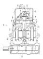
実施形態に係るコイルスプリング1を利用したベーン形圧縮機について、図1及び図2を参照しつつ説明する。
本実施形態でのコイルスプリング1は、ガイド部材としてのガイドピン3に支持されている。コイルスプリング1は、線状体[string material](ワイヤ[wire])5から作られ、かつ、表面硬化処理[surface-hardening process]が施されている。線状体5は、中心層と、表面硬化処理によって中心層の外側に形成された、中心層の硬度よりも高い硬度を有する硬化層とを有している。
線状体5の線径は、1mm以下に設定されている。線状体5の表面硬度は、ガイドピン3の表面硬度よりHv250以上高くされている。線状体5の硬化層の深さは、線状体5の半径の20%以下とされている。中心層の硬度は、Hv450~650とされている。線状体5の表面硬化処理では、フッ化処理が行なわれた後にガス軟窒化処理が行なわれる。線状体5は、少なくともC:0.51~0.59%,Si:1.2~1.6%,Mn:0.5~0.8%,Cr:0.5~0.8%の成分を含む。
本実施形態でのベーン形圧縮機101は、シリンダ103と、シリンダ103内に回転可能に設けられたロータ105と、ロータ105の外周面上に形成され、かつ、ロータ105の周方向に並べられた複数のベーン溝107と、往復動可能にベーン溝107内に設けられ、かつ、ロータ105の回転によってシリンダ103の内面に接触されるベーン109とを備えている。
ベーン溝107の底部側のベーン109の底部側端部[a bottom-side end of the vane 109 on a bottom side of the vane slot 107]には、ガイドピン3が設けられている。ガイドピン3によって、ベーン109をベーン溝107からの突出方向に付勢するコイルスプリング1が支持されている。本実施形態では、一つのベーン109に対して一対のガイドピン3が設けられている。本実施形態では、ガイドピン3は、ベーン溝107の底部から突設され、かつ、ベーン109に形成されたガイド孔141に挿入される態様で、「ベーン109の底部側端部に設けられ」る。しかし、ガイドピン3は、ベーン109から突設され、かつ、ベーン溝107の底部に形成されたガイド孔に挿入される態様で、「ベーン109の底部側端部に設けられ」てもよい。
ベーン形圧縮機101は、ケーシング111と、シリンダ103と、電動モータ113と、をも備えている。ケーシング111は、複数の分割部材で構成されている。分割部材同士の接合面にはシール部材が配置され、ケーシング111の内部には密封空間が形成される。分割部材は、ボルトなどの固定具[fasteners]によって互いに固定されている。シリンダ103及び電動モータ113は、ケーシング111内に収容されている。
シリンダ103は、ケーシング111の一側に収容されている。シリンダ103は、シリンダブロック115と、シリンダブロック115の両側に配置されたフロントサイドブロック117及びリアサイドブロック119とを備えている。フロントサイドブロック117及びリアサイドブロック119の外周面にはシール部材が配置されており、シリンダ103の内周面との気密性が実現されている。フロントサイドブロック117は、ボルトなどの固定具によってケーシング111に固定されている。
シリンダ103では、シリンダブロック115とフロントサイドブロック117とリアサイドブロック119とで形成される内部空間によって、密閉されたシリンダ室121が形成される。フロントサイドブロック117及びリアサイドブロック119に形成された吸入口(図示せず)からシリンダ室121に冷媒が吸入される。シリンダ室121内には、電動モータ113の回転軸123が挿通されている。回転軸123は、フロントサイドブロック117及びリアサイドブロック119に回転可能に支持されている。
電動モータ113は、ケーシング111の他側に収容されている。電動モータ113に隣接して設けられたモータ制御部125から電動モータ113に駆動電流が供給されて、回転軸123を駆動する。回転軸123には、ロータ105が設けられている。ロータ105は、回転軸123に固定され、回転軸123一体的に回転する。ロータ105は、シリンダ室121内に回転可能に収容されている。回転軸123の回転に伴って、ロータ105の外周面の一部がシリンダ室121のカム面(内周面)127と摺動接触する。ロータ105には、上述したベーン溝107が設けられている。
ベーン溝107は、ロータ105の外周面上に開口され、所定の深さを有している。ベーン溝107は、ロータ105の周方向に沿って等間隔に形成されている。ベーン溝107の各底部は、フロントサイドブロック117及びリアサイドブロック119に形成された吐出圧供給溝129及び中間圧供給溝131と連通されている。吐出圧供給溝129及び中間圧供給溝131は、フロントサイドブロック117及びリアサイドブロック119に形成された背圧供給路133を介して、リアサイドブロック119に隣接して配置された吐出室135内のオイル溜まり137と連通されている。
吐出室135は、ケーシング111とリアサイドブロック119とで形成された密封空間である。シリンダブロック115に形成された吐出口(図示せず)から吐出室135に、圧縮された冷媒が吐出される。吐出室135の底部には、冷媒から分離したオイルが溜められるオイル溜まり137が設けられている。オイル溜まり137に溜められたオイルは、回転軸123の回転に伴って背圧供給路133内に吸入され、吐出圧供給溝129及び中間圧供給溝131を介してベーン溝107の各底部に供給される。各ベーン溝107内には、ベーン109が収容されている。
ベーン109は、その頂縁[top edge]がロータ105の外周面から突出可能なように、ベーン溝107内に収容されている。吐出圧供給溝129及び中間圧供給溝131からベーン溝107の底部に供給される冷媒により発生する背圧によって、ベーン109はベーン溝107から突出され、ベーン109の頂縁がシリンダ室121のカム面127に当接される。ベーン109の頂縁がカム面127と当接すると、隣り合うベーン109とカム面127とロータ105の外周面とによって圧縮室139が形成される。ロータ105の回転に伴って圧縮室139の容積が変わり、圧縮室139に吸入された冷媒が圧縮される。ベーン109の底部側端部には、上述したガイドピン3が設けられている。
ガイドピン3の一端がベーン溝107の底部に圧入(固定)され、ガイドピン3の他端がベーン109に形成されたガイド孔141に挿入されている。なお、ガイドピン3の先端側部分は、ベーン109のベーン溝107からの最突出状態であっても、ガイド孔141内に残っている。ガイドピン3は、その外周でコイルスプリング1を支持するように設けられている。ガイドピン3は、ベーン溝107内でのベーン109の往復動によるコイルスプリング1の伸縮を案内し、コイルスプリング1の付勢力を安定してベーン109に付与させる。
コイルスプリング1は、ガイドピン3がベーン溝107内に固定された状態でベーン溝107内に収容され、その内部にガイドピン3が挿通されるように配置される。その後、ベーン溝107内にベーン109が収容され、コイルスプリング1の端部がベーン109の底面と当接される。コイルスプリング1の巻き径はガイド孔141の内径より大きく設定され、コイルスプリング1の端部がベーン109の底面と当接する。このため、ベーン109はコイルスプリング1によってベーン溝107から突出方向に付勢され、ベーン109の頂縁がカム面127に当接される。コイルスプリング1によってベーン109をカム面127へと付勢することで、ベーン109をベーン溝107から突出させるための背圧の不足を補い、ベーン109とカム面127との繰り返し衝突(チャタリング)が防止される。
ベーン溝107内に収容されたコイルスプリング1は、ベーン109の往復動に伴って伸縮され、ガイドピン3と摺動する。このため、コイルスプリング1の表面には、耐摩耗性を向上させるために、表面硬化処理が施される。しかし、上述したように、耐摩耗性の向上のみを考慮した表面硬化処理はコイルスプリング1の靱性を低下させ、その結果、コイルスプリング1の伸縮に対する強度が低下する恐れがある。
そこで、コイルスプリング1には、以下に説明する様々な条件が設定されている。まず、コイルスプリング1は、少なくともC:0.51~0.59%,Si:1.2~1.6%,Mn:0.5~0.8%,Cr:0.5~0.8%の成分を含む、弁バネ用シリコンクロム鋼オイルテンパー線からなる線状体5で作られる。線状体5を、所定の付勢力を得るように所定回数コイリング[coiling]することで、コイルスプリング1が形成される。
線状体5の線径は、1mm以下に設定されている。なお、本実施形態のコイルスプリング1では、表面硬化処理前の線状体5の硬度はHv600±50であり、ガイドピン3の硬度はHv450~550である。線状体5からなるコイルスプリング1には、以下に説明する表面硬化処理が施される。
なお、線状体5をコイリングしてコイルスプリング1の形状を形成した後で、かつ、表面硬化処理前には、まず、400℃で20分の熱処理[heat treatment]がコイルスプリング1に施される。熱処理後、コイルスプリング1に過荷重を負荷して予めコイルスプリング1をへたらすセッチング[pre-setting (pre-stressing) for preliminarily fatiguing the coil spring 1 by applying an excessive load to the coil spring 1]処理が施される。
表面硬化処理では、コイルスプリング1に、フッ化処理[fluorination treatment]を施した後、ガス軟窒化処理[gas nitrocarburizing treatment]が施される。ガス軟窒化処理の前にフッ化処理を施すことにより、コイルスプリング1の表面の酸化膜が除去される。このため、ガス軟窒化処理におけるコイルスプリング1の表面への窒素の浸透を促進できる。
ガス軟窒化処理後には、コイルスプリング1にWPC処理(株式会社不二製作所、株式会社不二機販、及び、株式会社不二WPC社の登録商標:ブラスト研削処理[abrasive blasting]の一種)が施される。WPC処理では、コイルスプリング1が籠に入れられ、噴射速度200m/s、及び、噴射角度15°~20°の条件で、籠を振りながらコイルスプリング1に向けて粒径40μmのスチールからなる粒子材が60秒間噴射される。
コイルスプリング1にガス軟窒化処理を施すことで、コイルスプリング1に十分な硬度と、十分な強度とを併せ持たせることができる。
上述した表面硬化処理が施されたコイルスプリング1は、中心層と、表面硬化処理によって中心層の外側に形成された、中心層の硬度よりも高い硬度を有する硬化層とを有している。本実施形態では、線状体5の表面硬度は、ガイドピン3の表面硬度よりHv250以上高くされている。また、硬化層の深さは、線状体5の半径の20%以下とされている。
上述したように、本実施形態では、ガイドピン3の硬度はHv450~550とされており、その下限はHv450である。このため、線状体5の表面硬度がガイドピン3の表面硬度よりHv250以上高くなるように、線状体5の表面硬度はHv700以上とされている。
なお、表面硬化処理の温度が高すぎたり、表面硬化処理の時間が長すぎたりすると、中心層の硬度が低下して、十分な強度が得られなくなる場合がある。このため、線状体5の硬化層の深さは、線状体5の半径の20%以下とされる。
上述したように、(1)線状体5の表面硬度をガイドピン3の表面硬度よりHv250以上高くすることで、線径1mm以下の線状体5から作られたコイルスプリング1、即ち、線径の細いコイルスプリング1が、ガイドピン3との摺動に対する良好な耐摩耗性を持つことができる。また、(2)硬化層の深さを線状体5の半径の20%以下とすることで、線径1mm以下の線状体5から作られたコイルスプリング1、即ち、線径の細いコイルスプリング1が、伸縮強度に対して良好な靱性を持つことができる。なお、上記(1)及び(2)の両方が満足されることがより好ましいが、いずれか一方のみでも、良好な耐摩耗性又は良好な靱性を得ることができる。
また、線状体5の中心層の硬度はHv450~650とされている。このため、コイルスプリング1の耐摩耗性を良好に維持しつつ、コイルスプリング1の十分な強度を維持できる。
さらに、線状体5の表面硬化処理が、フッ化処理と、フッ化処理後に行われるガス軟窒化処理とを含んでいるので、線状体5表面の酸化膜を除去した後に、低温での硬化層の形成を促進することができる。
またさらに、線状体5は、少なくともC:0.51~0.59%,Si:1.2~1.6%,Mn:0.5~0.8%,Cr:0.5~0.8%の成分を含む弁バネ用シリコンクロム鋼オイルテンパー線[silicon-chromium steel oil tempered wire for valve springs]であり、上記成分によって良好な耐摩耗性と良好な靱性とをコイルスプリング1に与えることができる。
さらに、ベーン形圧縮機101では、良好な耐摩耗性と良好な靱性とを併せ持つコイルスプリング1が、ガイドピン3に支持されてベーン109をベーン溝107からの突出方向に付勢する。このため、コイルスプリング1によって発生されるベーン109への付勢力を長期間維持でき、チャタリング防止機能の耐久性を向上できる。
以下の実施例を用いて詳細に説明するが、本発明は下記実施例によって限定されるものではない。
(実施例)
C:0.51~0.59%,Si:1.2~1.6%,Mn:0.5~0.8%,Cr:0.5~0.8%の成分を含み、硬度Hv600±50の弁バネ用シリコンクロム鋼オイルテンパー線からなる線状体5をコイリングしてコイルスプリング1の形状を形成した後、コイルスプリング1に400℃-20分の熱処理、及び、セッチング処理を施した。また、コイルスプリング1にフッ化処理が施され、コイルスプリング1から酸化膜が除去されて、低温でのガス軟窒化処理が可能な状態とされている。ガス軟窒化処理の条件を異ならせて以下の実験を行った。
C:0.51~0.59%,Si:1.2~1.6%,Mn:0.5~0.8%,Cr:0.5~0.8%の成分を含み、硬度Hv600±50の弁バネ用シリコンクロム鋼オイルテンパー線からなる線状体5をコイリングしてコイルスプリング1の形状を形成した後、コイルスプリング1に400℃-20分の熱処理、及び、セッチング処理を施した。また、コイルスプリング1にフッ化処理が施され、コイルスプリング1から酸化膜が除去されて、低温でのガス軟窒化処理が可能な状態とされている。ガス軟窒化処理の条件を異ならせて以下の実験を行った。
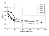
まず、0.45mmの線径のコイルスプリング1に対して、400℃-0.5時間、1時間、2時間、3時間及び4時間のガス軟窒化処理を施し、表面からの深さに対する硬度を測定した。なお、硬度測定は、ビッカース硬度計で行った。測定結果が図3に示されている。図3に示されるように、処理時間が長くなるほど、表面硬度(硬化層の硬度)は硬く(Hv値は高く)なり、かつ、硬化層の深さは深くなることがわかる。
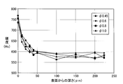
次に、0.45mm、0.6mm、0.8mm及び1mmの線径のコイルスプリング1に対して、400℃-0.5時間のガス軟窒化処理を施し、表面からの深さに対する硬度を測定した。測定結果が図4に示されている。図4に示されるように、処理時間が0.5時間であっても、全ての線径のコイルスプリング1で硬化層が深く形成されている。特に、0.45mmの細い線径のコイルスプリング1では、硬化層が50μmと深く形成されている。
さらに、0.45mm、0.6mm、0.8mm及び1mmの線径のコイルスプリングあに対して、400℃-0.5時間、1時間、2時間、3時間及び4時間のガス軟窒化処理を施し、引張試験を行った。試験結果が図5に示されている。ここで、引張試験で、塑性変形しなかったものが「×」印、塑性変形したものが「○」印で示されている。図5中の直線は、塑性変形の有無の境界を示す。図5に示されるように、1mm以下の線径のコイルスプリング1では、線径が細くなり、かつ、処理時間が長くなるほど、靱性が低下する(=塑性変形せずに壊れやすくなる)。
上述したように、ガス軟窒化処理の処理時間が長いほど、硬化層の深さは深くなる。そこで、引張試験に用いたコイルスプリング1の中心層(硬化していない部分)の割合を知るために、コイルスプリング1(線状体5)の半径に対する硬化層深さの割合を測定した。測定結果を下記[表1]に示す。なお、[表1]中の硬化層の深さの割合(%)の欄の下の数値は、線状体5の直径(単位:mm)である。

図5及び表1を比較すると、硬化層深さが線状体5の半径の20%以下、即ち、中心層が上記半径の80%以上であれば、靱性が良好であることが分かる。(図5中の靱性の低い「×」印に対応するデータは、φ0.45の下の3つのデータ、及び、φ0.6の下の2つのデータである。)従って、硬化層の深さを、線状体の半径の20%以下とすることで、良好な耐摩耗性と良好な靱性とを併せ持つコイルスプリング1を得ることができる。
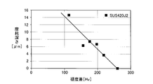
次に、ガイドピン(ガイド部材)3の表面硬度に対するコイルスプリング1の適正な表面硬度を調べた。硬度Hv450~550のマルテンサイトステンレス鋼[martensite stainless steel]SUS420J2で作られたガイドピン3と、異なる表面硬度のコイルスプリング1とを用いて摩耗試験を行った。試験結果が図6に示されている。なお、図6に示されるグラフの横軸は、ガイドピン3の表面硬度とコイルスプリング1の表面硬度との差を示している。図6に示されるように、硬度差がHv250以上であれば、コイルスプリング1に摩耗は生じない。
次に、表面硬度Hv513のガイドピン3と表面硬度Hv715(比較例)及びHv779(実施例)のコイルスプリングとを用いて摩耗試験を行った後、耐久試験を行った。試験結果を下記[表2]に示す。
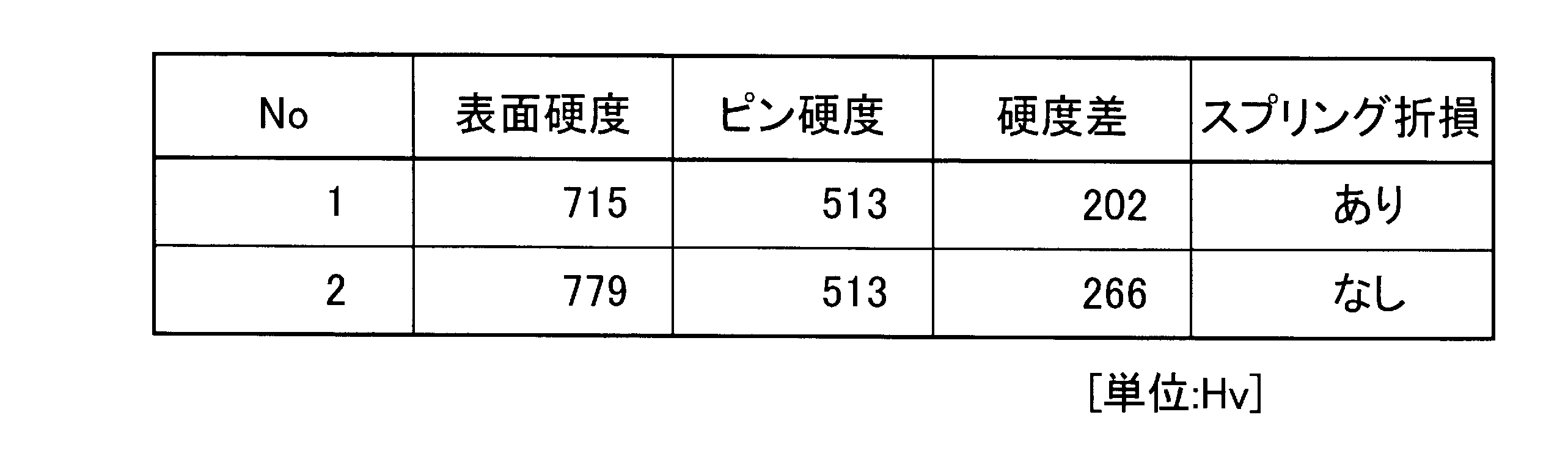
表2が示すように、硬度差がHv250以上であれば、コイルスプリング1には摩耗は生じず(上記摩耗試験参照)、かつ、折損も生じない。従って、本実施例における、ガイドピン(ガイド部材)3の表面硬度よりHv250以上の表面硬度の本実施例のコイルスプリング1は、ガイドピン3に対して優れた耐摩耗性を有している。
また、上述したように、ガス軟窒化処理の温度が高すぎると靱性が低下する(十分な強度が得られない)。そこで、温度480℃、430℃、400℃及び380℃でガス軟窒化処理を施したコイルスプリング1の中心層の硬度(すなわち、母材硬度)を測定し、かつ、引張試験を行った。測定/試験結果が下記[表3]に示されている。なお、表3中の引っ張り試験に対する「判定」は、ガス軟窒化処理が施されていない硬度Hv598のコイルスプリング1に対する引張強度の低下率が大きいものが「BAD」、低下率の小さい(=低下率(%)の値がほぼ100%、又は、100%以上)ものが「GOOD」である。「低下率(%)」のデータは、硬度Hv598のコイルスプリング1の引張強度に対する、比較対象の引張強度が百分率で示されている。
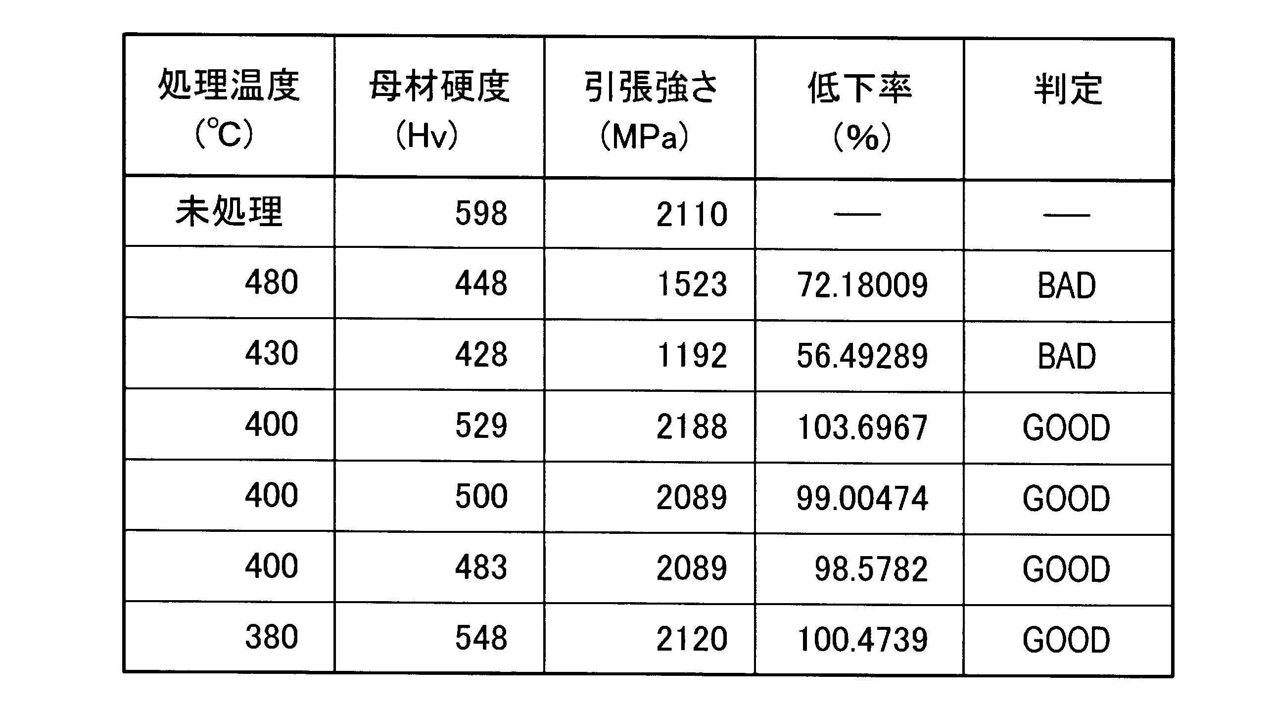
表3に示されるように、処理温度が400℃を超えると中心層の硬度(母材硬度)がHv450を下回って、引張強度が著しく低下する。なお、上述したように未処理の母材硬度(表面硬化処理前の線状体5の硬度)はHv600±50であり、その上限はHv650である。従って、本実施例における硬度Hv450~650の中心層を有するコイルスプリング1は、伸縮に対する優れた強度有している。
以上の結果から、本実施例によれば、良好な耐摩耗性と良好な靱性とを併せ持つコイルスプリング1を得ることができる。一方、比較例によれば、あまり魅力的でないコイルスプリングが得られる。
なお、上記実施形態に係るベーン形圧縮機では、ガイドピン(ガイド部材)3がコイルスプリング1に挿入されて、コイルスプリング1がガイドピン(ガイド部材)3によって支持された。しかし、コイルスプリングは、中空筒状に形成されたガイド部材の内部に挿入されて、ガイド部材によって支持されてもよい。
Claims (8)
- ガイド部材に支持された、線状体から作られて表面硬化処理が施されたコイルスプリングであって、
前記線状体が、中心層と、前記表面硬化処理によって前記中心層の外側に形成された、前記中心層の硬度よりも高い硬度を有する硬化層とを有し、
前記線状体の線径が、1mm以下であり、
前記線状体の表面硬度が、前記ガイド部材の表面硬度よりHv250以上高い、コイルスプリング。 - ガイド部材に支持された、線状体から作られて表面硬化処理が施されたコイルスプリングであって、
前記線状体が、中心層と、前記表面硬化処理によって前記中心層の外側に形成された、前記中心層の硬度よりも高い硬度を有する硬化層とを有し、
前記線状体の線径が、1mm以下であり、
前記硬化層の深さが、前記線状体の半径の20%以下である、コイルスプリング。 - ガイド部材に支持された、線状体から作られて表面硬化処理が施されたコイルスプリングであって、
前記線状体が、中心層と、前記表面硬化処理によって前記中心層の外側に形成された、前記中心層の硬度よりも高い硬度を有する硬化層とを有し、
前記線状体の線径が、1mm以下であり、
前記線状体の表面硬度が、前記ガイド部材の表面硬度よりHv250以上高く、
前記硬化層の深さが、前記線状体の半径の20%以下である、コイルスプリング。 - 請求項1~3の何れか一項に記載のコイルスプリングであって、
前記中心層の硬度が、Hv450~650である、コイルスプリング。 - 請求項1~4の何れか一項に記載のコイルスプリングであって、
前記表面硬化処理が、フッ化処理と、前記フッ化処理後に行われるガス軟窒化処理とを含む、コイルスプリング。 - 請求項1~5の何れか一項に記載のコイルスプリングであって、
前記線状体が、少なくともC:0.51~0.59%,Si:1.2~1.6%,Mn:0.5~0.8%,Cr:0.5~0.8%の成分を含む、コイルスプリング。 - 請求項1~6の何れか一項に記載のコイルスプリングであって、
前記ガイド部材が、前記コイルスプリングの内部に挿入されたガイドピンであり、
前記ガイドピンの硬度は、Hv450~550である、コイルスプリング。 - ベーン形圧縮機であって、
シリンダと、
前記シリンダ内に回転可能に設けられたロータと、
前記ロータの外周上に形成され、かつ、前記ロータの周方向に並べられた複数のベーン溝と、
往復可能に前記複数のベーン溝内に設けられ、かつ、前記ロータの回転によって前記シリンダの内面に接触すされる複数のベーンと、
前記複数のベーン毎に少なくとも一つ設けられた請求項1~6の何れか一項に記載のコイルスプリングと、を備え、
前記ベーン溝の底部側の前記ベーンの底部側端部に、前記ガイド部材が設けられており、
前記ベーンを前記ベーン溝からの突出方向に付勢するように、前記コイルスプリングが前記ガイド部材によって支持されている、ベーン形圧縮機。
Applications Claiming Priority (2)
| Application Number | Priority Date | Filing Date | Title |
|---|---|---|---|
| JP2015023821A JP2016148350A (ja) | 2015-02-10 | 2015-02-10 | コイルスプリング及びこのコイルスプリングを用いたベーン形圧縮機 |
| JP2015-023821 | 2015-02-10 |
Publications (1)
| Publication Number | Publication Date |
|---|---|
| WO2016129369A1 true WO2016129369A1 (ja) | 2016-08-18 |
Family
ID=56615183
Family Applications (1)
| Application Number | Title | Priority Date | Filing Date |
|---|---|---|---|
| PCT/JP2016/052010 Ceased WO2016129369A1 (ja) | 2015-02-10 | 2016-01-25 | コイルスプリング、及び、ベーン形圧縮機 |
Country Status (2)
| Country | Link |
|---|---|
| JP (1) | JP2016148350A (ja) |
| WO (1) | WO2016129369A1 (ja) |
Cited By (1)
| Publication number | Priority date | Publication date | Assignee | Title |
|---|---|---|---|---|
| CN110025838A (zh) * | 2019-05-31 | 2019-07-19 | 河南科技大学第一附属医院 | 一种急诊救治快速吸痰装置 |
Families Citing this family (1)
| Publication number | Priority date | Publication date | Assignee | Title |
|---|---|---|---|---|
| KR102522994B1 (ko) * | 2021-10-28 | 2023-04-19 | 엘지전자 주식회사 | 로터리 압축기 |
Citations (5)
| Publication number | Priority date | Publication date | Assignee | Title |
|---|---|---|---|---|
| JP2005200674A (ja) * | 2004-01-13 | 2005-07-28 | Air Water Inc | ステンレス鋼ばねの製造方法およびステンレス鋼ばね |
| JP2007224366A (ja) * | 2006-02-23 | 2007-09-06 | Sumitomo Electric Ind Ltd | 高強度ステンレス鋼ばねおよびその製造方法 |
| WO2008155864A1 (ja) * | 2007-06-21 | 2008-12-24 | Luzcom Inc. | Ni電鋳製コイル状超微細スプリング及びコイル状スプリング構造を一部に備えているNi電鋳パイプ並びにこれらの製造方法 |
| JP2009221967A (ja) * | 2008-03-17 | 2009-10-01 | Calsonic Kansei Corp | コンプレッサ |
| WO2012081571A1 (ja) * | 2010-12-13 | 2012-06-21 | 日本精線株式会社 | 銅合金線及び銅合金ばね |
Family Cites Families (2)
| Publication number | Priority date | Publication date | Assignee | Title |
|---|---|---|---|---|
| JP4771718B2 (ja) * | 2005-03-10 | 2011-09-14 | エア・ウォーターNv株式会社 | 金属の窒化方法 |
| JP4711403B2 (ja) * | 2005-07-26 | 2011-06-29 | 本田技研工業株式会社 | 鋼製ばね部材及びその製造方法 |
-
2015
- 2015-02-10 JP JP2015023821A patent/JP2016148350A/ja active Pending
-
2016
- 2016-01-25 WO PCT/JP2016/052010 patent/WO2016129369A1/ja not_active Ceased
Patent Citations (5)
| Publication number | Priority date | Publication date | Assignee | Title |
|---|---|---|---|---|
| JP2005200674A (ja) * | 2004-01-13 | 2005-07-28 | Air Water Inc | ステンレス鋼ばねの製造方法およびステンレス鋼ばね |
| JP2007224366A (ja) * | 2006-02-23 | 2007-09-06 | Sumitomo Electric Ind Ltd | 高強度ステンレス鋼ばねおよびその製造方法 |
| WO2008155864A1 (ja) * | 2007-06-21 | 2008-12-24 | Luzcom Inc. | Ni電鋳製コイル状超微細スプリング及びコイル状スプリング構造を一部に備えているNi電鋳パイプ並びにこれらの製造方法 |
| JP2009221967A (ja) * | 2008-03-17 | 2009-10-01 | Calsonic Kansei Corp | コンプレッサ |
| WO2012081571A1 (ja) * | 2010-12-13 | 2012-06-21 | 日本精線株式会社 | 銅合金線及び銅合金ばね |
Cited By (1)
| Publication number | Priority date | Publication date | Assignee | Title |
|---|---|---|---|---|
| CN110025838A (zh) * | 2019-05-31 | 2019-07-19 | 河南科技大学第一附属医院 | 一种急诊救治快速吸痰装置 |
Also Published As
| Publication number | Publication date |
|---|---|
| JP2016148350A (ja) | 2016-08-18 |
Similar Documents
| Publication | Publication Date | Title |
|---|---|---|
| TWI680025B (zh) | 用於傳送旋轉運動的機械接頭 | |
| CN115090877B (zh) | 旋转式压缩机的制造方法 | |
| US8770842B2 (en) | Sliding member and manufacturing method thereof | |
| JP4790767B2 (ja) | 斜板式液圧回転機 | |
| JP6072601B2 (ja) | 圧縮機用ベーンの製造方法 | |
| US20190368485A1 (en) | Pump actuator with stamp-aligned anti-rotation feature | |
| KR20020089136A (ko) | 사판식 압축기용 슈 및 그 제조방법 | |
| US8136417B2 (en) | Sliding device | |
| JP2016148350A (ja) | コイルスプリング及びこのコイルスプリングを用いたベーン形圧縮機 | |
| WO2006051656A1 (ja) | 摺動装置 | |
| JP2010196711A (ja) | ベーン、ローリングピストン式単段型回転式の密閉形圧縮機、給湯機、および、ベーンの製造方法 | |
| JP4830309B2 (ja) | 転がり摺動部品 | |
| JP2013155749A (ja) | 回転式圧縮機 | |
| CN103306929B (zh) | 液压旋转机械及液压旋转机械的制造方法 | |
| JP5601990B2 (ja) | 斜板式圧縮機及び斜板式圧縮機の斜板の表面処理方法 | |
| KR20100014295A (ko) | 비통합 반응층을 구비한 냉매 압축기의 슬라이딩 표면 | |
| KR100432740B1 (ko) | 밀폐형 압축기의 피스톤핀 제조방법 | |
| CN107034349A (zh) | 制造滑动凸轮轴的方法 | |
| JP2001329807A (ja) | エンジンの動弁機構用カムフォロア装置 | |
| JP2002266983A (ja) | 動弁機構の摺動部材及びその表面処理方法 | |
| JP2008215157A (ja) | エンジンバルブ | |
| JP6445293B2 (ja) | バルブリフタ及びその製造方法 | |
| US20200056816A1 (en) | Refrigerant compressor and freezer including same | |
| KR20170043645A (ko) | 버킷 태핏 및 그 제조 방법 | |
| JP5391667B2 (ja) | 斜板式コンプレッサ用スライディングシューの製造方法 |
Legal Events
| Date | Code | Title | Description |
|---|---|---|---|
| 121 | Ep: the epo has been informed by wipo that ep was designated in this application |
Ref document number: 16749014 Country of ref document: EP Kind code of ref document: A1 |
|
| NENP | Non-entry into the national phase |
Ref country code: DE |
|
| 122 | Ep: pct application non-entry in european phase |
Ref document number: 16749014 Country of ref document: EP Kind code of ref document: A1 |