WO2016129236A1 - 冷蔵庫 - Google Patents
冷蔵庫 Download PDFInfo
- Publication number
- WO2016129236A1 WO2016129236A1 PCT/JP2016/000508 JP2016000508W WO2016129236A1 WO 2016129236 A1 WO2016129236 A1 WO 2016129236A1 JP 2016000508 W JP2016000508 W JP 2016000508W WO 2016129236 A1 WO2016129236 A1 WO 2016129236A1
- Authority
- WO
- WIPO (PCT)
- Prior art keywords
- freezer compartment
- automatic ice
- ice maker
- refrigerator
- water
- Prior art date
- Legal status (The legal status is an assumption and is not a legal conclusion. Google has not performed a legal analysis and makes no representation as to the accuracy of the status listed.)
- Ceased
Links
Images

Classifications
-
- F—MECHANICAL ENGINEERING; LIGHTING; HEATING; WEAPONS; BLASTING
- F25—REFRIGERATION OR COOLING; COMBINED HEATING AND REFRIGERATION SYSTEMS; HEAT PUMP SYSTEMS; MANUFACTURE OR STORAGE OF ICE; LIQUEFACTION SOLIDIFICATION OF GASES
- F25C—PRODUCING, WORKING OR HANDLING ICE
- F25C1/00—Producing ice
- F25C1/22—Construction of moulds; Filling devices for moulds
- F25C1/25—Filling devices for moulds
-
- F—MECHANICAL ENGINEERING; LIGHTING; HEATING; WEAPONS; BLASTING
- F25—REFRIGERATION OR COOLING; COMBINED HEATING AND REFRIGERATION SYSTEMS; HEAT PUMP SYSTEMS; MANUFACTURE OR STORAGE OF ICE; LIQUEFACTION SOLIDIFICATION OF GASES
- F25C—PRODUCING, WORKING OR HANDLING ICE
- F25C1/00—Producing ice
- F25C1/22—Construction of moulds; Filling devices for moulds
- F25C1/24—Construction of moulds; Filling devices for moulds for refrigerators, e.g. freezing trays
-
- F—MECHANICAL ENGINEERING; LIGHTING; HEATING; WEAPONS; BLASTING
- F25—REFRIGERATION OR COOLING; COMBINED HEATING AND REFRIGERATION SYSTEMS; HEAT PUMP SYSTEMS; MANUFACTURE OR STORAGE OF ICE; LIQUEFACTION SOLIDIFICATION OF GASES
- F25D—REFRIGERATORS; COLD ROOMS; ICE-BOXES; COOLING OR FREEZING APPARATUS NOT OTHERWISE PROVIDED FOR
- F25D11/00—Self-contained movable devices, e.g. domestic refrigerators
- F25D11/02—Self-contained movable devices, e.g. domestic refrigerators with cooling compartments at different temperatures
-
- F—MECHANICAL ENGINEERING; LIGHTING; HEATING; WEAPONS; BLASTING
- F25—REFRIGERATION OR COOLING; COMBINED HEATING AND REFRIGERATION SYSTEMS; HEAT PUMP SYSTEMS; MANUFACTURE OR STORAGE OF ICE; LIQUEFACTION SOLIDIFICATION OF GASES
- F25C—PRODUCING, WORKING OR HANDLING ICE
- F25C2400/00—Auxiliary features or devices for producing, working or handling ice
- F25C2400/10—Refrigerator units
Definitions
- Embodiment of this invention is related with a refrigerator.
- the present invention has been made in view of the above circumstances, and an object thereof is to provide a refrigerator capable of changing the position of an automatic ice maker in a freezer compartment.
- the refrigerator of the present embodiment includes a freezer compartment, a refrigerator compartment, an automatic ice maker provided in the freezer compartment, a tank provided in the refrigerator compartment for storing water to be supplied to the automatic ice maker, and water in the tank
- a straight pipe portion extending in the vertical direction, a water injection pipe portion bent in a horizontal direction from a tip of the straight pipe portion, and a rotating portion for rotating the water injection pipe portion around an axis of the straight pipe portion. It is to be prepared.
- FIG. 2 is a cross-sectional view taken along the line AA in FIG.
- the refrigerator 10 has a storage space formed inside a heat insulating box 11 that opens to the front.
- This storage space is partitioned vertically by a heat insulating partition wall 12, a refrigerator compartment 20 is provided below the heat insulating partition wall 12, and a freezer compartment 30 is provided above the heat insulating partition wall 12.
- the refrigerating room 20 is a space cooled to a refrigerating temperature (for example, 0 to 3 ° C.), and the inside is further divided into upper and lower parts by an upper partition plate 21 and a lower partition plate 22.
- a water supply tank 50 is provided above the upper partition plate 21 toward one side of the heat insulation box 11, and a plurality of mounting shelves 23 are provided between the upper partition plate 21 and the lower partition plate 22.
- a drawer type storage container 24 is provided below the lower partition plate 22.
- the front opening of the refrigerator compartment 20 is closed by a refrigerator compartment door 25.
- the freezer compartment 30 is a space in which the inside is cooled to a freezing temperature (for example, ⁇ 18 ° C. or lower), and is partitioned vertically by a mounting shelf 31, and an automatic ice making machine 70 and an ice storage box above the mounting shelf 31. 71 is provided.
- the front opening of the freezer compartment 30 is closed by a freezer compartment door 32.
- a cooler cover 34 that forms a cooler chamber 33 with the rear surface of the heat insulating box 11, and a duct plate 35 that is disposed in front of the cooler cover 34 and that constitutes the rear surface of the freezer compartment 30. Is provided.
- the cooler chamber 33 accommodates a cooler 36 and a blower fan 37 inside.
- the cooler chamber 33 is connected to a refrigeration duct 38 formed between the cooler cover 34 and the duct plate 35, and air blown from the blower fan 37 flows into the refrigeration duct 38.
- the refrigeration duct 38 is connected to a refrigeration duct 41 provided on the back surface of the refrigeration chamber 20 via a flow path 40 provided with a damper 39 (see FIG. 3).
- the cooler 36 provided in the cooler chamber 33 constitutes a refrigeration cycle together with a compressor 42 provided at the lower part of the refrigerator 10, a condenser, a capillary tube (not shown), and the like, and refrigerant discharged from the compressor 42 is discharged. It is introduced via a condenser and a capillary tube. As a result, the cooler 36 is cooled to cool the air in the cooler chamber 33.
- the air in the cooler chamber 33 cooled by the cooler 36 is stored in the freezer compartment from the outlets 43 a and 43 b provided in the freezing duct 38.
- the inside of the freezer compartment 30 is cooled by blowing to 30
- the air in the cooler chamber 33 cooled by the cooler 36 is stored in the freezer compartment from the outlets 43 a and 43 b provided in the refrigeration duct 38.
- the freezing room 30 and the refrigerating room 20 are cooled by blowing out to the refrigerating room 20 from the blower outlet 44 provided in the refrigerating duct 41 while blowing out to 30.
- the air blown out to the refrigerator compartment 20 and the freezer compartment 30 cools the storage compartments 20 and 30 and then sucks the inlet 45 (see FIG. 2) and the heat insulating partition that opens into the freezer compartment 30 provided in the duct plate 35. It flows into the return duct 47 from the suction port 46 opened on the ceiling surface of the refrigerator compartment 20 provided on the wall 12, returns to the cooler chamber 33, and is cooled again by the cooler 36.
- the automatic ice making machine 70 includes an ice making tray 72 to which ice-making water is supplied from the water supply tank 50, and an ice making tray 72 that twists the ice making tray 72 to drop the generated ice into an ice storage box 71 provided below the ice making tray 72.
- An ice mechanism 73 and a detection lever 74 that swings up and down in the ice storage box 71 and detects the amount of ice stored by contacting the ice stored in the ice storage box 71 are provided.
- the automatic ice making machine 70 and the ice storage box 71 described above are suspended and fixed to the ceiling surface 30a of the freezer compartment 30 via a holder 75.
- the holder 75 includes a horizontal portion 75a having a substantially rectangular shape in plan view that covers the upper surface of the automatic ice making machine 70, and a pair of left and right vertical portions 75b and 75b that hang downward from the left and right ends of the horizontal portion 75a.
- Two rails 75c and 75d are provided on the upper and lower sides of the opposing surfaces of the pair of left and right vertical portions 75b and 75b.
- the automatic ice making machine 70 is inserted into the upper rail 75c, and the ice storage box 71 is placed in the lower rail 75d. Is inserted into the holder 75 in a state where the automatic ice maker 70 and the ice storage box 71 are stacked one above the other.
- a locking claw 13 that locks with the horizontal portion 75 a of the holder 75 is provided.
- This locking claw 13 is locked to the horizontal portion 75a of the holder 75, thereby fixing the holder 75 and the automatic ice making machine 70 and the ice storage box 71 held by the holder 75 in a suspended state on the ceiling surface 30a. It arrange
- the locking claw 13 that fixes the holder 75 to the left side of the ceiling surface 30 a of the freezing chamber 30 and the locking claw 13 that fixes the holder 75 to the right side are freezing. It is provided on each of the left and right sides of the ceiling surface 30 a of the chamber 30.
- the installation positions P1 and P2 where the automatic ice making machine 70 and the ice storage box 71 are installed via the holder 75 are provided at two different positions in the width direction.
- outlets 43a and 43b communicating with the refrigeration duct 38 are provided behind the two installation positions P1 and P2.
- the air outlets 43a and 43b are provided above the ice tray 72 of the automatic ice making machine 70 installed at the installation positions P1 and P2, and the air of the refrigeration duct 38 moves forward from the rear above the ice tray 72. It comes to blow out towards.
- the air outlet 43a located behind one (left side in FIG. 2) installation position P1 has a freezer compartment 30 as compared to the air outlet 43b located behind the other (right side in FIG. 2) installation position P2.
- the opening area which opens is small, and the opening area is different between the outlet 43a and the outlet 43b.
- the water supply tank 50 includes a container 51 that stores water therein and a lid 52 that closes an upper opening of the container 51, and is detachably mounted in the refrigerator compartment 20.
- the water stored in the water supply tank 50 is supplied to the automatic ice maker 70 as ice making water by a water supply device 53 provided behind the refrigerator compartment 20 and the freezer compartment 30.
- the water supply device 53 pumps the water stored in the water supply tank 50 with the water supply pump 54 and supplies the water to the ice tray 72 of the automatic ice making machine 70 provided in the freezer compartment 30 through the water supply pipe 55.
- the water supply pipe 55 includes a bent portion 56 extending from the rear side of the water supply tank 50 provided near one side portion of the heat insulating box 11 to the central portion in the width direction, and the bent portion 56.
- a straight pipe portion 57 extending upward and a water injection pipe portion 58 bent from the upper end of the straight pipe portion 57 and extending in the horizontal direction are provided.
- a power line (not shown) that supplies power to the automatic ice making machine 70 is provided along the water supply pipe 55.
- the straight pipe portion 57 penetrates the heat insulating partition wall 12 at the center in the width direction of the heat insulating box 11, that is, at an intermediate position between the two installation positions P 1 and P 2 provided in the freezer compartment 30. It passes through a refrigeration duct 38 formed between the duct plate 35 and an upper position of the freezer compartment 30.
- the straight pipe portion 57 is connected to the bent portion 56 so as to be rotatable about the axis via a turning portion 60 provided in the refrigerator compartment 20, and thereby extends forward from the upper end of the straight pipe portion 57.
- a water injection pipe portion 58 is provided so as to be rotatable around the axis of the straight pipe portion 57.
- the water injection pipe portion 58 enters the freezer compartment 30 from the freezing duct 38 through the lead-out hole 35a provided in the duct plate 35, and is located above the ice tray 72 of the automatic ice making machine 70 installed at one installation position P1. It extends to.
- a water injection port 58 a is formed below the tip of the water injection pipe 58, and water for making ice in the water supply tank 50 pumped up by the water supply pump 54 is injected from the water injection port 58 a to the ice tray 72.
- the automatic ice making machine 70 is used in order to move the automatic ice making machine 70 and the ice storage box 71 installed at one installation position P1 as shown in FIG. 2 to the other installation position P2.
- a power line for supplying power to the automatic ice maker 70 is removed and the holder 75 is removed from the ceiling surface 30 a of the freezer compartment 30.
- the straight pipe portion 57 of the water supply pipe 55 is rotated about the axis to move the water injection port 58a of the water injection pipe part 58 from one installation position P1 to the other installation position P2.
- the locking claw 13 provided at the installation position P2 is locked to the horizontal portion 75a of the holder 75, and the automatic ice maker 70 and the ice storage box 71 are provided at the other installation position P2 of the freezer compartment 30 together with the holder 75, and thereafter
- the transfer of the automatic ice maker 70 and the ice storage box 71 is completed by connecting the power supply line provided along the water supply pipe 55 to the automatic ice maker 70 arranged at the other installation position P2.
- the straight pipe portion 57 of the water supply pipe 55 is rotated around the axis so that the water injection pipe portion 58 is provided at any of the two installation positions P1 and P2. Since the water injection port 58 a can be moved, the position of the automatic ice making machine 70 can be changed in the freezer compartment 30.
- the automatic ice maker 70 is suspended and fixed to the ceiling surface 30a of the freezer compartment 30 via the holder 75, the automatic ice maker 70 is easily fixed in the freezer compartment 30. can do.
- the automatic ice maker 70 can be fixed to the heat-insulating box 11 having high strength by suspending and fixing the automatic ice maker 70 on the ceiling surface 30a of the freezer compartment 30 so that the automatic ice maker 70 can be stably installed. it can.
- an automatic ice maker 70 and an ice storage box 71 fixed on the ceiling surface 30a of the freezer compartment 30 are provided with a mounting shelf 31 that divides the freezer compartment 30 up and down.
- tube 55 of the water supply apparatus 53 is arrange
- the turning operation of the turning portion 60 is not hindered, and the water injection pipe portion 58 can be smoothly turned around the axis of the straight pipe portion 57.
- the blower outlets 43a and 43b are each provided in the back of two installation positions P1 and P2, even if it installs the automatic ice maker 70 in any installation position The low-temperature air cooled by the cooler 36 can be directly blown onto the automatic ice making machine 70.
- the opening area opened to the freezer compartment 30 is different between the outlet 43a provided behind one installation position P1 and the outlet 43b provided behind the other installation position P2. Therefore, by installing the automatic ice making machine 70 at one installation position P1 located in front of the air outlet 43a having a small opening area, the water in the ice tray 72 can be frozen relatively slowly to generate highly transparent ice. By installing the automatic ice making machine 70 at the other installation position P2 located in front of the air outlet 43b having a large opening area, water in the ice tray 72 can be rapidly frozen to generate ice in a short time. it can.
Landscapes
- Engineering & Computer Science (AREA)
- Physics & Mathematics (AREA)
- Mechanical Engineering (AREA)
- Thermal Sciences (AREA)
- General Engineering & Computer Science (AREA)
- Chemical & Material Sciences (AREA)
- Combustion & Propulsion (AREA)
- Devices That Are Associated With Refrigeration Equipment (AREA)
Abstract
【課題】自動製氷機の位置を冷凍室内で変更することができる冷蔵庫を提供する。 【解決手段】冷凍室30と、冷蔵室20と、冷凍室30に設けられる自動製氷機70と、冷蔵室20に設けられ自動製氷機70に供給する水を貯水するタンク50と、タンク50の水を自動製氷機70に給水する給水装置53とを備え、冷凍室30は、自動製氷機70を設置する設置位置P1,P2を幅方向に異なる位置に2箇所備え、給水装置53は、2箇所の設置位置P1,P2の間において上下方向に延びる直管部57と、直管部57の先端から水平方向に屈曲する注水管部58と、注水管部58を直管部57の軸回りに回動させる回動部60とを備える。
Description
本発明の実施形態は、冷蔵庫に関するものである。
従来、使用者が、冷凍室内の自在な位置で製氷することができるように、製氷皿と貯氷箱を移動させることができる冷蔵庫が提案されている(下記特許文献1参照)。
しかし、近年、冷蔵室内に設置した給水タンクの水を給水装置を介して自動製氷機に給水して自動的に製氷を行う冷蔵庫が主流となっているが、この種の冷蔵庫では、自動製氷機の場所が固定されており使用者の使い勝手に応じて製氷する場所を選択することができない。
本発明は上記事情を考慮してなされたものであり、自動製氷機の位置を冷凍室内で変更することができる冷蔵庫を提供することを目的とする。
本実施形態の冷蔵庫は、冷凍室と、冷蔵室と、前記冷凍室に設けられる自動製氷機と、前記冷蔵室に設けられ前記自動製氷機に供給する水を貯水するタンクと、前記タンクの水を前記自動製氷機に給水する給水装置とを備え、前記冷凍室は、前記自動製氷機を設置する設置位置を幅方向に異なる位置に2箇所備え、前記給水装置は、2箇所の前記設置位置の間において上下方向に延びる直管部と、前記直管部の先端から水平方向に屈曲する注水管部と、前記注水管部を前記直管部の軸回りに回動させる回動部とを備えるものである。
以下、図面に基づいて本発明の一実施形態について説明する。
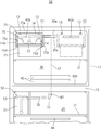
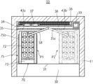
本実施形態に係る冷蔵庫10は、図1及び図2に示すように、前面に開口する断熱箱体11の内部に貯蔵空間が形成されている。この貯蔵空間は、断熱仕切壁12によって上下に区画され、断熱仕切壁12の下方に冷蔵室20が設けられ、断熱仕切壁12の上方に冷凍室30が設けられている。
冷蔵室20は、冷蔵温度(例えば、0~3℃)に冷却される空間であって、内部が上仕切板21及び下仕切板22によって更に上下に区画されている。この例では、上仕切板21の上方には断熱箱体11の一方側部に寄せて給水タンク50が設けられ、上仕切板21及び下仕切板22の間には複数段の載置棚23が設けられ、下仕切板22の下方には引き出し式の収納容器24が設けられている。冷蔵室20の前面開口部は冷蔵室扉25で閉塞されている。
冷凍室30は、内部が冷凍温度(例えば、-18℃以下)に冷却される空間であって、載置棚31によって上下に区画され、載置棚31の上方に自動製氷機70及び貯氷箱71が設けられている。冷凍室30の前面開口部は冷凍室扉32で閉塞されている。
冷凍室30の後部には、断熱箱体11背面との間で冷却器室33を形成する冷却器カバー34と、冷却器カバー34の前方に配置され冷凍室30の背面を構成するダクト板35が設けられている。
冷却器室33は、内部に冷却器36と送風ファン37とが収納されている。冷却器室33は、冷却器カバー34とダクト板35の間に形成された冷凍ダクト38に接続されており、送風ファン37から吹き出した空気が冷凍ダクト38へ流れ込む。冷凍ダクト38は、ダンパ39(図3参照)が設けられた流路40を介して冷蔵室20の背面に設けられた冷蔵ダクト41に接続されている。
冷却器室33に設けられた冷却器36は、冷蔵庫10の下部に設けた圧縮機42や、不図示の凝縮器やキャピラリーチューブ等とともに冷凍サイクルを構成し、圧縮機42から吐出される冷媒が凝縮器及びキャピラリーチューブを介して導入される。これにより、冷却器36は低温化して冷却器室33内の空気を冷却する。
そして、ダンパ39が流路40を閉止した状態で送風ファン37が回転すると、冷却器36によって冷却された冷却器室33の空気は、冷凍ダクト38に設けられた吹出口43a、43bより冷凍室30へ吹き出し冷凍室30内を冷却する。また、ダンパ39が流路40を開放した状態で送風ファン37が回転すると、冷却器36によって冷却された冷却器室33の空気は、冷凍ダクト38に設けられた吹出口43a、43bより冷凍室30へ吹き出すとともに、冷蔵ダクト41に設けられた吹出口44より冷蔵室20へ吹き出すことで、冷凍室30及び冷蔵室20を冷却する。
そして、冷蔵室20及び冷凍室30へ吹き出した空気は、各貯蔵室20,30を冷却した後、ダクト板35に設けられた冷凍室30に開口する吸込口45(図2参照)及び断熱仕切壁12に設けられた冷蔵室20の天井面に開口する吸込口46からリターンダクト47に流れ込み冷却器室33に戻り再び冷却器36によって冷却される。
そして、冷蔵室20及び冷凍室30へ吹き出した空気は、各貯蔵室20,30を冷却した後、ダクト板35に設けられた冷凍室30に開口する吸込口45(図2参照)及び断熱仕切壁12に設けられた冷蔵室20の天井面に開口する吸込口46からリターンダクト47に流れ込み冷却器室33に戻り再び冷却器36によって冷却される。
自動製氷機70は、給水タンク50から製氷用の水が供給される製氷皿72と、製氷皿72を捻って製氷皿72の下方に設けられた貯氷箱71へ生成された氷を落下させる離氷機構73と、貯氷箱71内を上下に揺動し貯氷箱71に蓄積された氷と接触することで貯氷量を検知する検知レバ74とを備える。
上記した自動製氷機70及び貯氷箱71は、ホルダー75を介して冷凍室30の天井面30aに吊り下げて固定されている。具体的には、ホルダー75は、自動製氷機70の上面を覆う平面視略長方形の水平部75aと、水平部75aの左右両端から下方に垂れ下がる左右一対の垂直部75b、75bとを備える。左右一対の垂直部75b、75bの対向面には、上下に2本のレール75c,75dが設けられており、上方のレール75cに自動製氷機70が挿入され、下方のレール75dに貯氷箱71が挿入されることで、自動製氷機70及び貯氷箱71が上下に重ねた状態でホルダー75に保持される。
冷凍室30の天井面30aには、ホルダー75の水平部75aと係止する係止爪13が設けられている。この係止爪13は、ホルダー75の水平部75aに係止することで、ホルダー75とホルダー75に保持された自動製氷機70及び貯氷箱71を、天井面30aに吊り下げ状態で固定し、冷凍室30に設けられた載置棚31の上方に間隔をあけて配置する。
本実施形態では、図2に示すように、冷凍室30の天井面30aの左側部にホルダー75を固定する係止爪13と、右側部にホルダー75を固定する係止爪13とが、冷凍室30の天井面30aの左右両側部にそれぞれ設けられている。これにより、冷凍室30には、ホルダー75を介して自動製氷機70及び貯氷箱71を設置する設置位置P1,P2が幅方向に異なる位置に2箇所設けられている。
また、2箇所の設置位置P1,P2の後方には、冷凍ダクト38に連通する吹出口43a、43bが設けられている。具体的には、吹出口43a、43bは、設置位置P1、P2に設置される自動製氷機70の製氷皿72より上方に設けられ、冷凍ダクト38の空気が製氷皿72の上方を後方から前方に向けて吹き出すようになっている。この例では、一方(図2において左側)の設置位置P1の後方に位置する吹出口43aが、他方(図2において右側)の設置位置P2の後方に位置する吹出口43bに比べて冷凍室30に開口する開口面積が小さくなっており、吹出口43aと吹出口43bとの間で開口面積が異なっている。
給水タンク50は、内部に水を貯留する容器51とその容器51の上部開口を閉塞する蓋52とを備え、冷蔵室20内に着脱自在に装着されている。給水タンク50に貯留された水は、冷蔵室20及び冷凍室30の後方に設けられた給水装置53によって製氷用水として自動製氷機70に供給される。
給水装置53は、給水タンク50に貯留された水を給水ポンプ54で汲み上げて給水管55を介して冷凍室30に設けられた自動製氷機70の製氷皿72に給水する。
給水管55は、図1及び図2に示すように、断熱箱体11の一方側部に寄せて設けられた給水タンク50の後方から幅方向中央部へ延びる屈曲部56と、屈曲部56から上方へ延びる直管部57と、直管部57の上端から屈曲して水平方向に延出する注水管部58とを備える。なお、本実施形態では、自動製氷機70に給電する不図示の電源ラインが給水管55に沿わせて設けられている。
直管部57は、断熱箱体11の幅方向中央部、つまり、冷凍室30に設けられた2箇所の設置位置P1,P2の中間位置において断熱仕切壁12を貫通し、冷却器カバー34とダクト板35との間に形成された冷凍ダクト38を通って冷凍室30の上方位置まで延設されている。
直管部57は、冷蔵室20に設けられた回動部60を介して屈曲部56に対して軸回りに回動可能に連結され、これにより、直管部57の上端から前方へ延出する注水管部58が直管部57の軸回りに回動可能に設けられている。
注水管部58は、ダクト板35に設けられた導出孔35aを通って冷凍ダクト38から冷凍室30へ進入し、一方の設置位置P1に設置された自動製氷機70の製氷皿72の上方位置まで延びている。注水管部58の先端下側には、注水口58aが形成されており、給水ポンプ54で汲み上げた給水タンク50の製氷用水を注水口58aから製氷皿72へ注水する。
このような構成の冷蔵庫10において、図2に示すような一方の設置位置P1に設置された自動製氷機70及び貯氷箱71を他方の設置位置P2に移設するには、まず、自動製氷機70に給電する電源ラインを自動製氷機70から取り外すとともに、ホルダー75を冷凍室30の天井面30aから取り外す。そして、給水管55の直管部57を軸回りに回動させて注水管部58の注水口58aを、一方の設置位置P1から他方の設置位置P2へ移動させる。
そして、設置位置P2に設けられた係止爪13をホルダー75の水平部75aに係止させてホルダー75とともに自動製氷機70及び貯氷箱71を冷凍室30の他方の設置位置P2に設け、その後、給水管55に沿わせて設けられた電源ラインを他方の設置位置P2に配置された自動製氷機70に接続することで、自動製氷機70及び貯氷箱71の移設が完了する。
以上のような構成を備える本実施形態の冷蔵庫10では、給水管55の直管部57を軸回りに回動させることで、2箇所の設置位置P1,P2のいずれにも注水管部58の注水口58aを移動させることができるため、自動製氷機70の位置を冷凍室30内で変更することができる。
しかも、本実施形態の冷蔵庫では、自動製氷機70がホルダー75を介して冷凍室30の天井面30aに吊り下げて固定されているため、自動製氷機70を容易に冷凍室30内に取付固定することができる。また、自動製氷機70を冷凍室30の天井面30aに吊り下げて固定することで、強度の高い断熱箱体11に対して固定することができ自動製氷機70を安定して設置することができる。しかも、冷凍室30の天井面30aに固定された自動製氷機70及び貯氷箱71の下方には、冷凍室30を上下に区画する載置棚31が設けられているため、万一、自動製氷機70及び貯氷箱71が落下することがあっても、直下に位置する載置棚31によって支持され、落下の衝撃を抑えることができ、自動製氷機70及び貯氷箱71等の破損を抑えることができる。
また、本実施形態の冷蔵庫10では、給水装置53の給水管55において直管部57を回動させる回動部60が冷蔵温度に冷却される冷蔵室20内に配設されているため、凍結により回動部60の回動動作が阻害されることがなく、注水管部58を直管部57の軸回りにスムーズに回動させることができる。
また、本実施形態の冷蔵庫10では、吹出口43a,43bが、2箇所の設置位置P1,P2の後方のそれぞれに設けられているため、いずれの設置位置に自動製氷機70を設置しても、冷却器36によって冷却された低温の空気を自動製氷機70に直接吹き付けることができる。しかも、本実施形態では、一方の設置位置P1の後方に設けられた吹出口43aと他方の設置位置P2の後方に設けられた吹出口43bとで冷凍室30に開口する開口面積が異なっているため、開口面積の小さい吹出口43aの前方に位置する一方の設置位置P1に自動製氷機70を設置することで、製氷皿72の水を比較的ゆっくりと凍結させ透明度の高い氷を生成することができ、開口面積の大きい吹出口43bの前方に位置する他方の設置位置P2に自動製氷機70を設置することで、製氷皿72の水を急速に凍結させ短時間で氷を生成することができる。
なお、上記した本実施形態では、冷凍室30の天井面30aに自動製氷機70及び貯氷箱71を固定する場合について説明したが、例えば、冷凍室30に設けられた載置棚31の下面に吊り下げて固定したり、冷凍室30の底面30bに固定してもよい。
以上、本発明の実施形態を説明したが、これらの実施形態は例として提示したものであり、発明の範囲を限定することを意図していない。これらの実施形態は、その他の様々な形態で実施されることが可能であり、発明の趣旨を逸脱しない範囲で、種々の省略、置き換え、変更を行うことができる。これらの実施形態やその変形は、発明の範囲や要旨に含まれると同様に、特許請求の範囲に記載された発明とその均等の範囲に含まれるものである。
10…冷蔵庫、11…断熱箱体、13…係止爪、20…冷蔵室、30…冷凍室、30a…天井面、31…載置棚、32…冷凍室扉、33…冷却器室、34…冷却器カバー、35…ダクト板、36…冷却器、37…送風ファン、38…冷凍ダクト、43a…吹出口、43b…吹出口、44…吹出口、50…給水タンク、53…給水装置、54…給水ポンプ、55…給水管、56…屈曲部、57…直管部、58…注水管部、60…回動部、70…自動製氷機、71…貯氷箱、72…製氷皿、73…離氷機構、75…ホルダー
Claims (6)
- 冷凍室と、冷蔵室と、前記冷凍室に設けられる自動製氷機と、前記冷蔵室に設けられ前記自動製氷機に供給する水を貯水するタンクと、前記タンクの水を前記自動製氷機に給水する給水装置とを備え、
前記冷凍室は、前記自動製氷機を設置する設置位置を幅方向に異なる位置に2箇所備え、
前記給水装置は、2箇所の前記設置位置の間において上下方向に延びる直管部と、前記直管部の先端から水平方向に屈曲する注水管部と、前記注水管部を前記直管部の軸回りに回動させる回動部とを備える冷蔵庫。 - 前記自動製氷機が、前記冷凍室の天井面又は前記冷凍室を上下に仕切る棚の下面に吊り下げて固定されている請求項1に記載の冷蔵庫。
- 前記冷凍室を上下に仕切る棚を備え、
前記自動製氷機が、前記冷凍室の天井面に吊り下げて固定され、前記棚の上方に設けられている請求項1又は2に記載の冷蔵庫。 - 前記回動部が、前記冷蔵室に設けられている請求項1~3のいずれか1項に記載の冷蔵庫。
- 冷却器で冷却された空気を前記冷凍室へ吹き出す吹出口が、2箇所の前記設置位置の後方にそれぞれ設けられている請求項1~4のいずれか1項に記載の冷蔵庫。
- 一方の前記設置位置の後方に設けられた吹出口と他方の前記設置位置の後方に設けられた吹出口とで前記冷凍室に開口する面積が異なる請求項5に記載の冷蔵庫。
Priority Applications (1)
| Application Number | Priority Date | Filing Date | Title |
|---|---|---|---|
| CN201680006292.7A CN107208957A (zh) | 2015-02-09 | 2016-02-01 | 冰箱 |
Applications Claiming Priority (2)
| Application Number | Priority Date | Filing Date | Title |
|---|---|---|---|
| JP2015023338A JP6460819B2 (ja) | 2015-02-09 | 2015-02-09 | 冷蔵庫 |
| JP2015-023338 | 2015-02-09 |
Publications (1)
| Publication Number | Publication Date |
|---|---|
| WO2016129236A1 true WO2016129236A1 (ja) | 2016-08-18 |
Family
ID=56615163
Family Applications (1)
| Application Number | Title | Priority Date | Filing Date |
|---|---|---|---|
| PCT/JP2016/000508 Ceased WO2016129236A1 (ja) | 2015-02-09 | 2016-02-01 | 冷蔵庫 |
Country Status (3)
| Country | Link |
|---|---|
| JP (1) | JP6460819B2 (ja) |
| CN (1) | CN107208957A (ja) |
| WO (1) | WO2016129236A1 (ja) |
Families Citing this family (1)
| Publication number | Priority date | Publication date | Assignee | Title |
|---|---|---|---|---|
| CN115127278B (zh) * | 2021-03-26 | 2023-08-29 | 海信容声(广东)冰箱有限公司 | 一种冰箱 |
Citations (11)
| Publication number | Priority date | Publication date | Assignee | Title |
|---|---|---|---|---|
| JPS61213570A (ja) * | 1985-03-20 | 1986-09-22 | 株式会社日立製作所 | 冷蔵庫の製氷コ−ナ− |
| JPH05256564A (ja) * | 1992-03-13 | 1993-10-05 | Matsushita Refrig Co Ltd | 冷蔵庫 |
| JPH08178491A (ja) * | 1994-12-26 | 1996-07-12 | Sharp Corp | 冷凍冷蔵庫 |
| JPH0989426A (ja) * | 1995-09-28 | 1997-04-04 | Hitachi Ltd | 冷蔵庫 |
| JPH09126640A (ja) * | 1995-10-31 | 1997-05-16 | Mitsubishi Electric Corp | 冷蔵庫 |
| JPH09196553A (ja) * | 1995-12-29 | 1997-07-31 | Samsung Electronics Co Ltd | 冷蔵庫の冷凍室の棚構造 |
| JP2001272151A (ja) * | 2000-03-29 | 2001-10-05 | Toshiba Corp | 冷蔵庫 |
| JP2002206829A (ja) * | 2001-01-11 | 2002-07-26 | Matsushita Refrig Co Ltd | 自動製氷給水システム |
| JP2002228316A (ja) * | 2001-02-06 | 2002-08-14 | Fujitsu General Ltd | 自動製氷装置を備えた冷蔵庫とその制御方法 |
| US20060112715A1 (en) * | 2004-11-30 | 2006-06-01 | Lg Electronics Inc. | Ice making device for refrigerator |
| JP2014006013A (ja) * | 2012-06-26 | 2014-01-16 | Panasonic Corp | 冷凍庫 |
Family Cites Families (5)
| Publication number | Priority date | Publication date | Assignee | Title |
|---|---|---|---|---|
| JPH11101538A (ja) * | 1997-09-26 | 1999-04-13 | Sanyo Electric Co Ltd | 冷蔵庫 |
| JP2003287364A (ja) * | 2002-03-27 | 2003-10-10 | Sanyo Electric Co Ltd | 冷蔵庫 |
| CN201803558U (zh) * | 2010-04-02 | 2011-04-20 | 合肥美的荣事达电冰箱有限公司 | 一种冰箱 |
| CN201715808U (zh) * | 2010-04-02 | 2011-01-19 | 合肥美的荣事达电冰箱有限公司 | 一种冰箱 |
| CN203405048U (zh) * | 2013-06-27 | 2014-01-22 | 海信容声(广东)冰箱有限公司 | 一种冰箱用自动制冰机给水组件 |
-
2015
- 2015-02-09 JP JP2015023338A patent/JP6460819B2/ja not_active Expired - Fee Related
-
2016
- 2016-02-01 CN CN201680006292.7A patent/CN107208957A/zh active Pending
- 2016-02-01 WO PCT/JP2016/000508 patent/WO2016129236A1/ja not_active Ceased
Patent Citations (11)
| Publication number | Priority date | Publication date | Assignee | Title |
|---|---|---|---|---|
| JPS61213570A (ja) * | 1985-03-20 | 1986-09-22 | 株式会社日立製作所 | 冷蔵庫の製氷コ−ナ− |
| JPH05256564A (ja) * | 1992-03-13 | 1993-10-05 | Matsushita Refrig Co Ltd | 冷蔵庫 |
| JPH08178491A (ja) * | 1994-12-26 | 1996-07-12 | Sharp Corp | 冷凍冷蔵庫 |
| JPH0989426A (ja) * | 1995-09-28 | 1997-04-04 | Hitachi Ltd | 冷蔵庫 |
| JPH09126640A (ja) * | 1995-10-31 | 1997-05-16 | Mitsubishi Electric Corp | 冷蔵庫 |
| JPH09196553A (ja) * | 1995-12-29 | 1997-07-31 | Samsung Electronics Co Ltd | 冷蔵庫の冷凍室の棚構造 |
| JP2001272151A (ja) * | 2000-03-29 | 2001-10-05 | Toshiba Corp | 冷蔵庫 |
| JP2002206829A (ja) * | 2001-01-11 | 2002-07-26 | Matsushita Refrig Co Ltd | 自動製氷給水システム |
| JP2002228316A (ja) * | 2001-02-06 | 2002-08-14 | Fujitsu General Ltd | 自動製氷装置を備えた冷蔵庫とその制御方法 |
| US20060112715A1 (en) * | 2004-11-30 | 2006-06-01 | Lg Electronics Inc. | Ice making device for refrigerator |
| JP2014006013A (ja) * | 2012-06-26 | 2014-01-16 | Panasonic Corp | 冷凍庫 |
Also Published As
| Publication number | Publication date |
|---|---|
| CN107208957A (zh) | 2017-09-26 |
| JP6460819B2 (ja) | 2019-01-30 |
| JP2016145691A (ja) | 2016-08-12 |
Similar Documents
| Publication | Publication Date | Title |
|---|---|---|
| US7921668B2 (en) | Refrigerator having controlled ice maker and dispenser | |
| CN105928308B (zh) | 冰箱 | |
| US9080799B2 (en) | Refrigerator | |
| CN102213517B (zh) | 冰箱 | |
| KR101327739B1 (ko) | 냉동고 | |
| KR101519134B1 (ko) | 냉장고 | |
| KR20130101371A (ko) | 냉장고 | |
| CN106257168A (zh) | 冰箱的制冰机以及制造所述制冰机的方法 | |
| JP5872143B2 (ja) | 冷蔵庫 | |
| KR20090075911A (ko) | 냉장고 | |
| JP6061808B2 (ja) | 冷蔵庫 | |
| CN105874290B (zh) | 冷冻柜 | |
| JP6460819B2 (ja) | 冷蔵庫 | |
| JP2014047958A (ja) | 冷蔵庫 | |
| KR20080040450A (ko) | 냉장고도어 제빙실 | |
| WO2009072745A2 (en) | Ice-making system installed in refrigerator door | |
| JP6448919B2 (ja) | 冷蔵庫 | |
| US20190331396A1 (en) | Ice Maker and Refrigerator Having Same | |
| JP2017032153A (ja) | 冷蔵庫 | |
| JP5990731B2 (ja) | 冷蔵庫 | |
| CN204630223U (zh) | 冰箱 | |
| KR100918447B1 (ko) | 냉장고의 송풍장치 | |
| US20160370071A1 (en) | Refrigerator and ice making method thereof | |
| KR102365542B1 (ko) | 냉장고 | |
| KR100614315B1 (ko) | 냉장고 |
Legal Events
| Date | Code | Title | Description |
|---|---|---|---|
| 121 | Ep: the epo has been informed by wipo that ep was designated in this application |
Ref document number: 16748884 Country of ref document: EP Kind code of ref document: A1 |
|
| NENP | Non-entry into the national phase |
Ref country code: DE |
|
| 122 | Ep: pct application non-entry in european phase |
Ref document number: 16748884 Country of ref document: EP Kind code of ref document: A1 |