WO2016129023A1 - 波長変換部材及びそれを用いた光起電力デバイス - Google Patents
波長変換部材及びそれを用いた光起電力デバイス Download PDFInfo
- Publication number
- WO2016129023A1 WO2016129023A1 PCT/JP2015/006268 JP2015006268W WO2016129023A1 WO 2016129023 A1 WO2016129023 A1 WO 2016129023A1 JP 2015006268 W JP2015006268 W JP 2015006268W WO 2016129023 A1 WO2016129023 A1 WO 2016129023A1
- Authority
- WO
- WIPO (PCT)
- Prior art keywords
- wavelength conversion
- conversion member
- phosphor
- fluoride
- light
- Prior art date
- Legal status (The legal status is an assumption and is not a legal conclusion. Google has not performed a legal analysis and makes no representation as to the accuracy of the status listed.)
- Ceased
Links
Images

Classifications
-
- C—CHEMISTRY; METALLURGY
- C09—DYES; PAINTS; POLISHES; NATURAL RESINS; ADHESIVES; COMPOSITIONS NOT OTHERWISE PROVIDED FOR; APPLICATIONS OF MATERIALS NOT OTHERWISE PROVIDED FOR
- C09K—MATERIALS FOR MISCELLANEOUS APPLICATIONS, NOT PROVIDED FOR ELSEWHERE
- C09K11/00—Luminescent, e.g. electroluminescent, chemiluminescent materials
- C09K11/08—Luminescent, e.g. electroluminescent, chemiluminescent materials containing inorganic luminescent materials
- C09K11/77—Luminescent, e.g. electroluminescent, chemiluminescent materials containing inorganic luminescent materials containing rare earth metals
- C09K11/7728—Luminescent, e.g. electroluminescent, chemiluminescent materials containing inorganic luminescent materials containing rare earth metals containing europium
- C09K11/7732—Halogenides
- C09K11/7733—Halogenides with alkali or alkaline earth metals
-
- C—CHEMISTRY; METALLURGY
- C09—DYES; PAINTS; POLISHES; NATURAL RESINS; ADHESIVES; COMPOSITIONS NOT OTHERWISE PROVIDED FOR; APPLICATIONS OF MATERIALS NOT OTHERWISE PROVIDED FOR
- C09K—MATERIALS FOR MISCELLANEOUS APPLICATIONS, NOT PROVIDED FOR ELSEWHERE
- C09K11/00—Luminescent, e.g. electroluminescent, chemiluminescent materials
- C09K11/08—Luminescent, e.g. electroluminescent, chemiluminescent materials containing inorganic luminescent materials
- C09K11/61—Luminescent, e.g. electroluminescent, chemiluminescent materials containing inorganic luminescent materials containing fluorine, chlorine, bromine, iodine or unspecified halogen elements
- C09K11/615—Halogenides
- C09K11/616—Halogenides with alkali or alkaline earth metals
-
- G—PHYSICS
- G02—OPTICS
- G02B—OPTICAL ELEMENTS, SYSTEMS OR APPARATUS
- G02B5/00—Optical elements other than lenses
- G02B5/20—Filters
-
- H—ELECTRICITY
- H10—SEMICONDUCTOR DEVICES; ELECTRIC SOLID-STATE DEVICES NOT OTHERWISE PROVIDED FOR
- H10F—INORGANIC SEMICONDUCTOR DEVICES SENSITIVE TO INFRARED RADIATION, LIGHT, ELECTROMAGNETIC RADIATION OF SHORTER WAVELENGTH OR CORPUSCULAR RADIATION
- H10F77/00—Constructional details of devices covered by this subclass
- H10F77/40—Optical elements or arrangements
- H10F77/42—Optical elements or arrangements directly associated or integrated with photovoltaic cells, e.g. light-reflecting means or light-concentrating means
- H10F77/45—Wavelength conversion means, e.g. by using luminescent material, fluorescent concentrators or up-conversion arrangements
-
- H—ELECTRICITY
- H10—SEMICONDUCTOR DEVICES; ELECTRIC SOLID-STATE DEVICES NOT OTHERWISE PROVIDED FOR
- H10F—INORGANIC SEMICONDUCTOR DEVICES SENSITIVE TO INFRARED RADIATION, LIGHT, ELECTROMAGNETIC RADIATION OF SHORTER WAVELENGTH OR CORPUSCULAR RADIATION
- H10F10/00—Individual photovoltaic cells, e.g. solar cells
- H10F10/10—Individual photovoltaic cells, e.g. solar cells having potential barriers
- H10F10/16—Photovoltaic cells having only PN heterojunction potential barriers
- H10F10/164—Photovoltaic cells having only PN heterojunction potential barriers comprising heterojunctions with Group IV materials, e.g. ITO/Si or GaAs/SiGe photovoltaic cells
- H10F10/165—Photovoltaic cells having only PN heterojunction potential barriers comprising heterojunctions with Group IV materials, e.g. ITO/Si or GaAs/SiGe photovoltaic cells the heterojunctions being Group IV-IV heterojunctions, e.g. Si/Ge, SiGe/Si or Si/SiC photovoltaic cells
- H10F10/166—Photovoltaic cells having only PN heterojunction potential barriers comprising heterojunctions with Group IV materials, e.g. ITO/Si or GaAs/SiGe photovoltaic cells the heterojunctions being Group IV-IV heterojunctions, e.g. Si/Ge, SiGe/Si or Si/SiC photovoltaic cells the Group IV-IV heterojunctions being heterojunctions of crystalline and amorphous materials, e.g. silicon heterojunction [SHJ] photovoltaic cells
-
- Y—GENERAL TAGGING OF NEW TECHNOLOGICAL DEVELOPMENTS; GENERAL TAGGING OF CROSS-SECTIONAL TECHNOLOGIES SPANNING OVER SEVERAL SECTIONS OF THE IPC; TECHNICAL SUBJECTS COVERED BY FORMER USPC CROSS-REFERENCE ART COLLECTIONS [XRACs] AND DIGESTS
- Y02—TECHNOLOGIES OR APPLICATIONS FOR MITIGATION OR ADAPTATION AGAINST CLIMATE CHANGE
- Y02E—REDUCTION OF GREENHOUSE GAS [GHG] EMISSIONS, RELATED TO ENERGY GENERATION, TRANSMISSION OR DISTRIBUTION
- Y02E10/00—Energy generation through renewable energy sources
- Y02E10/50—Photovoltaic [PV] energy
- Y02E10/52—PV systems with concentrators
Definitions
- the present invention relates to a wavelength conversion member and a photovoltaic device using the same.
- the present invention relates to a wavelength conversion member having improved photoelectric conversion efficiency, and a photovoltaic device using the wavelength conversion member.
- the photoelectric conversion efficiency of ultraviolet light is lower than the photoelectric conversion efficiency of visible light.
- the solar cell has low photoelectric conversion efficiency for ultraviolet light in the wavelength range of 300 nm to less than 400 nm, and high photoelectric conversion efficiency in visible light and infrared light regions in the wavelength range of 400 nm to less than 1200 nm.
- ultraviolet light within a wavelength range of less than 380 nm is likely to damage the solar cell, and for this reason, in a conventional solar cell, ultraviolet light within a wavelength range of less than 380 nm, for example, is cut by a filter.
- barium halide activated Eu 2+ specifically barium fluoride activated Eu 2+ are disclosed (see, for example, Patent Document 1).
- barium fluoride activated with Eu 2+ emits light only at low temperatures, and hardly emits light at temperatures of 25 ° C. or higher, so it can not sufficiently convert ultraviolet light into visible light or infrared light. The That is, in the wavelength conversion member using the conventional fluoride fluorescent substance, it was difficult to improve the output of the solar cell at high temperature.
- An object of the present invention is to provide a wavelength conversion member capable of enhancing the photoelectric conversion efficiency even at high temperatures and improving the output of the solar cell, and a photovoltaic device using the same.
- the wavelength conversion member which concerns on the 1st aspect of this invention is equipped with the fluoride fluorescent substance activated by Ce ⁇ 3+> or Eu ⁇ 2+ >. Then, when the internal quantum efficiency measured at 30 ° C. is 100%, the fluoride phosphor has an internal quantum efficiency measured at 80 ° C. of 85% or more.
- a photovoltaic device comprises the wavelength conversion member described above.
- FIG. 1 is a cross-sectional view schematically showing an example of a solar cell module as a photovoltaic device according to an embodiment of the present invention.
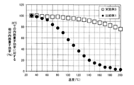
- FIG. 2 is a graph showing the relationship between relative internal quantum efficiency and temperature in the phosphors of Example 3 and Comparative Example 1.
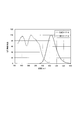
- FIG. 3 is a graph showing an emission spectrum and an excitation spectrum of the phosphor of Example 3.
- the wavelength conversion member according to the present embodiment absorbs ultraviolet light in sunlight and converts it into visible light or infrared light. As a result, visible light or infrared light having high spectral sensitivity is increased, which makes it possible to improve the photoelectric conversion efficiency of the solar cell.
- the wavelength conversion member needs to exhibit high transmittance to visible light and infrared light in which the solar battery cell is a highly sensitive wavelength range. This is because if the transmittance is lowered when the wavelength conversion member is provided, the photoelectric conversion efficiency is lowered due to the decrease of the transmittance than the improvement of the photoelectric conversion efficiency by the wavelength conversion member.
- the wavelength conversion member according to the present embodiment is cerium ion (Ce 3+ ) or A fluoride phosphor activated with europium ion (Eu 2+ ) is provided.
- a fluoride fluorescent substance as a wavelength conversion member, the fall of the transmittance
- the internal quantum efficiency measured at 80 ° C. when the internal quantum efficiency measured at 30 ° C. is 100%, the internal quantum efficiency measured at 80 ° C. is 85% or more.
- the fluoride fluorescent substance excellent in the temperature characteristic since the fluoride fluorescent substance excellent in the temperature characteristic is used, it becomes possible to absorb the ultraviolet light sufficiently even at high temperature in summer to perform wavelength conversion, and to improve the output of the solar cell.
- the fluoride phosphor preferably has an internal quantum efficiency measured at 80 ° C. of 90% or more, and more preferably 95% or more .
- the fluoride fluorescent material needs to have cerium ion (Ce 3+ ) or europium ion (Eu 2+ ) as a luminescent center.
- Ce 3+ and Eu 2+ adopt a mechanism of light absorption and emission based on 4f n ⁇ 4f n -1 5d 1 permissible transition. Therefore, the wavelengths of absorption and emission change depending on the host crystal in which they are activated. Therefore, by selecting an appropriate host crystal with Ce 3+ or Eu 2+ as the emission center, it is possible to convert light in the near ultraviolet to violet region into light in a wavelength range in which the solar battery cell has high sensitivity.
- the matrix of the fluoride phosphor in this embodiment is preferably a fluoride containing an alkaline earth metal and magnesium. That is, the matrix of the fluoride phosphor is preferably a fluoride containing magnesium and at least one element selected from the group consisting of calcium (Ca), strontium (Sr) and barium (Ba). This is preferable because the emission intensity is high and the quantum efficiency tends to be high even at high temperature. The reason why the emission intensity at high temperature is good is presumed to be as follows.
- the crystal structure of the fluoride phosphor is a strong host crystal in which [MgF 6 ] 4- units having an octahedral structure share F to be bonded in large numbers.
- CaF 2 : Eu 2+ is conventionally known as a fluoride fluorescent material having Eu 2+ as a luminescent center.
- the host compound is calcium fluoride (CaF 2 ) and the luminescent center is Eu 2+ .
- CaF 2 : Eu 2+ absorbs ultraviolet light of 300 nm or more and less than 400 nm and emits visible light of about 425 nm, it can be used as a wavelength conversion material for solar cells.
- the refractive index of CaF 2 is 1.43, which is close to the refractive index of the sealing material described later, the transmittance in visible light and infrared light is reduced even if CaF 2 : Eu 2+ is dispersed in the sealing material. It becomes a difficult wavelength conversion member.
- the wavelength conversion member using CaF 2 : Eu 2+ can not sufficiently improve the output of the solar cell.
- the reason why the output of a solar cell can not be improved by such conventional fluoride phosphors is the temperature quenching of the phosphors.
- Thermal quenching is a phenomenon in which the internal quantum efficiency decreases as the temperature of the phosphor increases.
- the temperature of the solar cell may rise to 80 ° C. or more depending on the use environment. Therefore, when the temperature quenching of the phosphor used for the wavelength conversion member is remarkable, the improvement of the efficiency due to the wavelength conversion can not be sufficiently obtained in the use environment where the temperature of the solar cell is high.
- CaF 2 : Eu 2+ can not sufficiently improve the output of the solar cell because the internal quantum efficiency at 80 ° C. decreases to 80% or less of the internal quantum efficiency at 30 ° C.
- all other conventional fluoride phosphors have remarkable temperature quenching, and can not exhibit high internal quantum efficiency even at 80 ° C. or higher. Therefore, the wavelength conversion member which can fully improve the output of a solar cell was not able to be obtained.
- the fluoride phosphor is activated by Ce 3+ or Eu 2+ , and when the internal quantum efficiency measured at 30 ° C. is 100%, the internal quantum measured at 80 ° C. Efficiency is 85% or more. Therefore, wavelength conversion is efficiently performed even in a use environment where the temperature of the solar cell is high, and the output of the solar cell can be improved.
- the inventor knows, there is no reported example of a fluoride phosphor activated with Ce 3+ or Eu 2+ which has such a small temperature quenching, and a fluorescence which achieves both a low refractive index and a good temperature quenching property. Having a body was not a surprise.
- a rare earth ion other than Ce 3+ and Eu 2+ as an emission center is also known.
- the emission center is a rare earth ion other than Ce 3+ and Eu 2+ , it is difficult to obtain an inorganic phosphor that absorbs ultraviolet light having a wavelength of 300 to 400 nm even if the composition of the host crystal is adjusted.
- Ce 3+ and Eu 2+ it is possible to obtain an inorganic phosphor that absorbs ultraviolet light having a wavelength of 300 to 400 nm by adjusting the composition of the host crystal. The main reasons are as follows.
- the rare earth ions from Ce to Yb have electrons in the 4f orbital.
- ions other than Ce 3+ and Eu 2+ generally absorb and emit light by transition in the 4f shell.
- the electrons in the 4f orbital are inside the electrons in the 5s orbital and the 5p orbital and shielded, fluctuation of the energy level due to the influence of the surroundings hardly occurs.
- an inorganic phosphor whose center of emission is ions other than Ce 3+ and Eu 2+
- the change in emission wavelength is small even if the composition of the host crystal is adjusted, and an inorganic phosphor that absorbs ultraviolet light of 300 to 400 nm is used. Hard to get.
- Ce 3+ and Eu 2+ absorb and emit light by the transition between the 5d and 4f shells, ie, the transition between 4f n and 4f n ⁇ 5d.
- the emission wavelength can be adjusted by adjusting the composition of the host crystal in the case of light emission based on the transition from the 4f n ⁇ 1 5d 1 level to the 4f orbital. It is possible to make a big change. This large change in emission wavelength makes it possible to obtain an inorganic phosphor that absorbs ultraviolet light of 300 to 400 nm in the case of an inorganic phosphor having Ce 3+ and Eu 2+ as emission centers.
- the fluoride phosphor is preferably based on the compound represented by the general formula (1).
- the fluoride fluorescent substance excellent in the absorptivity of ultraviolet light, quantum efficiency, and a temperature characteristic can be obtained.
- the alkaline earth metal is preferably at least one element selected from the group consisting of calcium (Ca), strontium (Sr) and barium (Ba).
- M 3 Mg 4 F 14 (1) (Wherein, M is an alkaline earth metal)
- the crystal structure in which a part of the atoms of the host crystal having the composition represented by the general formula (1) is substituted with one of Ce 3+ and Eu 2+ is represented by, for example, the chemical formula (2) or (3) Ru. (M 1-x Ce x ) 3 Mg 4 F 14 (2) (Wherein, M is one or more alkaline earth metals selected from the group consisting of Ca, Sr and Ba, and x satisfies 0 ⁇ x ⁇ 0.3).
- M is one or more alkaline earth metals selected from the group consisting of Ca, Sr and Ba, and y satisfies 0 ⁇ y ⁇ 0.3).
- x is preferably 0.003 ⁇ x ⁇ 0.1, more preferably 0.01 ⁇ x ⁇ 0.1.
- y is preferably 0.003 ⁇ y ⁇ 0.1, more preferably 0.01 ⁇ y ⁇ 0.1.
- the fluoride phosphor may contain an alkali metal. This makes it possible to control the excitation spectrum and the emission spectrum derived from Eu 2+ or Ce 3+ .
- the alkali metal is preferably at least one element selected from the group consisting of lithium (Li), sodium (Na), potassium (K), rubidium (Rb) and cesium (Cs).
- the fluoride phosphor may contain a halogen element other than fluorine as long as the crystal structure of the fluoride phosphor is not impaired. Thereby, it is possible to control the excitation spectrum and the emission spectrum derived from Eu 2+ or Ce 3+ and the refractive index of the phosphor.
- the halogen element is preferably at least one element selected from the group consisting of chlorine (Cl), bromine (Br) and iodine (I).
- the fluoride phosphor may contain manganese ion (Mn 2+ ). As a result, energy transfer from Eu 2+ or Ce 3+ to Mn 2+ occurs, and it becomes possible to emit light on the long wavelength side by causing Mn 2+ to be a luminescent center. Moreover, the fluoride fluorescent substance may contain oxygen in the range which does not impair the crystal structure of the said fluoride fluorescent substance. This makes it possible to control the refractive index of the phosphor.
- the fluoride phosphor may contain a rare earth element other than the element that is the emission center.
- a rare earth element it is possible to include a large number of elements serving as a light emission center, and it is possible to increase the absorptivity of ultraviolet light.
- rare earth elements scandium (Sc), yttrium (Y), lanthanum (La), praseodymium (Pr), neodymium (Nd), promethium (Pm), samarium (Sm), gadolinium (Gd), terbium (Tb) And preferably at least one element selected from the group consisting of dysprosium (Dy), holmium (Ho), erbium (Er), thulium (Tm), ytterbium (Yb) and lutetium (Lu).
- Dy dysprosium
- Ho holmium
- Er erbium
- Tm thulium
- Lu lutetium
- the fluoride fluorescent substance may contain an element other than Mg which can take a hexacoordinated state. By including such an element, it is possible to control the refractive index of the phosphor.
- the element capable of taking a hexacoordinated state is, for example, selected from the group consisting of aluminum (Al), gallium (Ga), scandium (Sc), zirconium (Zr), manganese (Mn) and lutetium (Lu). It is preferable that it is at least one element.
- the fluoride fluorescent material preferably has a crystal structure of the same type as Pb 3 Nb 4 O 12 F 2 . As a result, a phosphor having excellent absorptivity, quantum efficiency and temperature characteristics can be obtained.
- a fluoride fluorescent substance makes a compound represented by Chemical formula (4) a base.
- a phosphor having excellent absorptivity, quantum efficiency and temperature characteristics is obtained.
- the fluoride fluorescent substance is based on the compound represented by the chemical formula (5). This makes it possible to adjust the refractive index of the fluoride phosphor.
- the fluoride phosphor preferably has a center particle diameter (D 50 ) of 0.1 ⁇ m or more and less than 100 ⁇ m, and more preferably 0.3 ⁇ m or more and less than 30 ⁇ m.
- D 50 center particle diameter
- the central particle size of the fluoride fluorescent material can be measured, for example, by a laser diffraction scattering type particle size distribution measuring apparatus.
- the fluoride phosphor preferably has an average particle diameter of 0.1 ⁇ m or more and less than 100 ⁇ m, and more preferably 0.3 ⁇ m or more and less than 30 ⁇ m.
- the average particle diameter of the fluoride fluorescent material is in this range, it is possible to sufficiently absorb ultraviolet light in sunlight and obtain a wavelength conversion member in which a decrease in transmittance of visible light and infrared light is suppressed. It becomes possible.
- the average particle diameter of fluoride fluorescent substance is defined as the average value of the longest axis length in arbitrary 20 or more fluorescent substance particle
- the fluoride phosphor preferably has an emission wavelength of 440 nm or more. Therefore, since the ultraviolet light can be converted to the region where the spectral sensitivity of the solar battery cell is high, the output of the solar battery can be further improved.
- the refractive index of the fluoride phosphor is preferably 1.41 or more and less than 1.57, more preferably 1.44 or more and less than 1.54, and particularly preferably 1.47 or more and less than 1.51. preferable.
- the wavelength conversion member of the present embodiment further includes a sealing material for dispersing the fluoride fluorescent material. That is, in the wavelength conversion member, the fluoride fluorescent material is preferably dispersed in the sealing material. By dispersing the fluoride fluorescent substance in the sealing material, it is possible to efficiently absorb ultraviolet light and to convert the wavelength to visible light or infrared light. Moreover, it becomes easy to shape
- the sealing material for example, at least one resin material selected from the group consisting of ethylene-vinyl acetate copolymer (EVA), polyvinyl butyral (PVB), polyimide, polyethylene, polypropylene, polyethylene terephthalate (PET) is used.
- EVA ethylene-vinyl acetate copolymer
- PVB polyvinyl butyral
- PET polyethylene terephthalate
- the refractive index of these resins is 1.41 or more and less than 1.57.
- the particle diameter of the fluorescent material is several tens of nm in order not to reduce the transmittance of visible light and infrared light.
- the phosphor is miniaturized to a certain extent, or the refractive index of the phosphor is comparable to that of the sealing material.
- the larger the particle size of the phosphor the smaller the defect density in the phosphor, and the less the energy loss at the time of light emission, so the luminous efficiency becomes higher.
- the refractive index of the phosphor be approximately the same as that of the sealing material.
- the refractive index of the fluoride phosphor is preferably 1.41 or more and less than 1.57.
- the inorganic fluorescent substance is used in various light emitting devices, for example, a fluorescent lamp, an electron tube, a plasma display panel (PDP), a white LED, and the like.
- an inorganic fluorescent substance is a compound in which a part of a crystalline compound is partially substituted with an element capable of becoming an ion emitting fluorescence. Ions having such characteristics are called "emission centers" as described above. Then, ions as a luminescent center are introduced into the host as the crystalline compound.
- Examples of the base of the phosphor used for such applications include oxides, nitrides, sulfides, oxynitrides, oxysulfides, acid halides and the like.
- the refractive index of these base compounds is 1.6 or more, which is higher than that of the sealing material. Therefore, in the wavelength conversion member in which the phosphor consisting of such a matrix is dispersed in the sealing material, visible light and infrared light are reflected due to the difference in refractive index between the sealing material and the phosphor, and the transmittance is It has caused deterioration of the photoelectric conversion efficiency due to the decrease.
- the wavelength conversion member of the present embodiment uses a fluoride phosphor as the phosphor.
- a fluoride having a refractive index as low as that of the sealing material is a matrix compound. Therefore, since the refractive index difference between the sealing material and the phosphor is small, the reflection of visible light and infrared light is reduced in the wavelength conversion member, and the deterioration of the photoelectric conversion efficiency due to the reduction of the transmittance is suppressed. Is possible.
- the content of the fluoride fluorescent substance in the sealing material is preferably 0.1 vol% to less than 10 vol%, and more preferably 1 vol% to less than 5 vol%. It becomes possible to obtain the wavelength conversion member which fully absorbed ultraviolet light and suppressed the fall of the transmittance
- the fluoride fluorescent substance in the wavelength conversion member of this embodiment can be manufactured by a well-known method. Specifically, similar to yttrium aluminum garnet (YAG), it can be synthesized using a known solid phase reaction.
- YAG yttrium aluminum garnet
- fluorides of alkaline earth metal elements, fluorides of rare earth elements, and fluorides of magnesium are prepared.
- the raw material powder is prepared to have a stoichiometric composition of the desired compound or a composition close to this, and thoroughly mixed using a mortar, a ball mill or the like.
- the fluoride fluorescent substance of this embodiment can be prepared by baking mixed raw material with an electric furnace etc. using baking containers, such as an alumina crucible. When firing the mixed material, it is preferable to heat the mixture material at a firing temperature of 700 to 1000 ° C. for several hours in the air or in a weak reducing atmosphere.
- additives such as reaction accelerator may be added to the raw material.
- ammonium fluoride (NH 4 F) is preferable because it suppresses the elimination of fluorine.
- the wavelength conversion member of this embodiment can be obtained by mixing with the sealing material the fluorescent substance obtained by making it above, and shape
- the thickness of the wavelength conversion member is not particularly limited, but preferably 200 ⁇ m to 1000 ⁇ m, for example.
- the wavelength conversion member according to the present embodiment includes the fluoride phosphor activated with Ce 3+ or Eu 2+ . And when the fluoride fluorescent substance makes internal quantum efficiency measured at 30 degreeC 100%, internal quantum efficiency measured at 80 degreeC is 85% or more. Further, in the present embodiment, as a result of detailed investigation of a fluoride phosphor activated with Ce 3+ or Eu 2 + , which was conventionally considered to have a large temperature quenching, it was found that some have excellent temperature quenching. It is obtained. Therefore, the wavelength conversion member can efficiently convert the wavelength of ultraviolet light without reducing the transmittance of visible light or infrared light, and the output of the photovoltaic device can be sufficiently improved even at high temperatures. It becomes.
- the photovoltaic device of the present embodiment includes the wavelength conversion member described above. Specifically, as a photovoltaic device according to the present embodiment, a solar cell module 1 as shown in FIG. 1 can be mentioned.
- the solar cell module 1 includes a solar cell 10 as a photoelectric conversion element, a wavelength conversion member 20 disposed on the light receiving surface 13 side of the solar cell 10, and a surface of the wavelength conversion member 20. And a surface protection layer 30 disposed.
- the solar cell module 1 includes a back surface sealing member 40 disposed on the back surface 14 which is a surface opposite to the light receiving surface 13 of the solar battery cell 10 and a back surface protective layer disposed on the back surface of the back surface sealing member 40 And 50. That is, in the solar cell module 1, the surface protection layer 30, the wavelength conversion member 20, the solar cell 10, the back surface sealing member 40, and the back surface protection layer 50 are provided in this order from the top in the figure. .
- the photovoltaic cell 10 absorbs light incident from the light receiving surface 13 of the photovoltaic cell 10 to generate photovoltaic power.
- the solar battery cell 10 is formed using a semiconductor material such as crystalline silicon, gallium arsenide (GaAs), indium phosphide (InP), or the like.
- the solar battery cell 10 is made of, for example, a stack of crystalline silicon and amorphous silicon. Electrodes (not shown) are provided on the light receiving surface 13 of the solar battery cell 10 and the back surface 14 which is the surface opposite to the light receiving surface 13.
- the photovoltaic power generated by the solar battery cell 10 is supplied to the outside through the electrode.
- a wavelength conversion member 20 is disposed on the light receiving surface 13 of the solar battery cell 10. As shown in FIG. 1, the wavelength conversion member 20 includes a sealing material 21 for sealing the light receiving surface 13 of the solar battery cell 10, and a fluoride fluorescent material 25 dispersed in the sealing material 21. The wavelength conversion member 20 prevents the moisture from entering the solar battery cell 10 by the sealing material 21 and improves the strength of the entire solar battery module 1.
- the surface protective layer 30 is provided on the light receiving surface 13 side of the solar battery cell 10, and protects the solar battery cell 10 from the external environment and transmits light to be absorbed by the solar battery cell 10.
- a glass substrate can be used as the surface protective layer 30.
- the surface protective layer 30 may be made of polycarbonate, acrylic resin, polyester, or fluorinated polyethylene in addition to the glass substrate.
- the back surface protective layer 50 is a back sheet provided on the back surface 14 side of the solar battery cell 10.
- the back surface protective layer 50 may be a transparent substrate made of the same glass or plastic as the surface protective layer 30.
- the back surface sealing member 40 is disposed on the back surface 14 of the solar battery cell 10 to prevent the entry of moisture into the solar battery cell 10 and improve the strength of the entire solar battery module 1.
- the back surface sealing member 40 is made of, for example, the same material as the material that can be used for the sealing material 21 of the wavelength conversion member 20.
- the material of the back surface sealing member 40 may be the same as or different from the material of the sealing material 21 of the wavelength conversion member 20.
- a metal foil or the like may be provided between the back surface sealing member 40 and the back surface protective layer 50 so that the light incident from the surface protective layer 30 side is more absorbed by the solar battery cell 10. Thereby, the light reaching the back surface protective layer 50 from the surface protective layer 30 can be reflected in the direction of the solar battery cell 10.
- the solar cell module 1 when the solar cell module 1 is irradiated with ultraviolet light 70 and sunlight including visible light and infrared light 80, the ultraviolet light 70 and visible light and infrared light 80 pass through the surface protection layer 30.
- the light is incident on the wavelength conversion member 20.
- the visible light and the infrared light 80 which are incident on the wavelength conversion member 20 are transmitted through the wavelength conversion member 20 as they are without being substantially converted by the fluoride fluorescent material 25 and are irradiated to the solar battery cell 10.
- the ultraviolet light 70 incident on the wavelength conversion member 20 is converted to visible light and infrared light 80 which are light on the long wavelength side by the fluoride phosphor 25, and then is applied to the solar battery cell 10.
- the solar cell 10 generates a photovoltaic power 90 by the irradiated visible light and infrared light 80, and the photovoltaic power 90 is supplied to the outside of the solar cell module 1 through a terminal (not shown).
- the wavelength conversion member 20 of the present embodiment uses the fluoride fluorescent material 25 which is significantly suppressed in the decrease of the internal quantum efficiency at high temperature and is excellent in the temperature characteristic. Therefore, ultraviolet light can be effectively used without reducing the transmittance in visible light or infrared light, and the output of the solar cell module 1 can be improved even at high temperatures.
- Examples 1 to 16 and Comparative Example 1 (Preparation of phosphor)
- the fluoride phosphors of Examples 1 to 16 and Comparative Example 1 were synthesized using a preparation method utilizing a solid phase reaction, and their characteristics were evaluated.
- the following compound powder was used as a raw material.
- each raw material was weighed at a ratio shown in Table 1.
- the raw materials were sufficiently dry-mixed using a magnetic mortar and a magnetic pestle to obtain sintered raw materials.
- the fired material was transferred to an alumina crucible and fired for 2 hours in a reducing atmosphere (in a 96% nitrogen 4% hydrogen mixed gas atmosphere) at a temperature of 850 ° C. using a tubular atmosphere furnace.
- the fired product was crushed using an alumina mortar and an alumina pestle to obtain the phosphors of Examples 1 to 16.
- each raw material was weighed at a ratio shown in Table 1.
- the raw materials were sufficiently dry-mixed using a magnetic mortar and a magnetic pestle to obtain sintered raw materials.
- the fired material was transferred to an alumina crucible and fired for 2 hours in a reducing atmosphere (in a 96% nitrogen 4% hydrogen mixed gas atmosphere) at a temperature of 1200 ° C. using a tubular atmosphere furnace.
- the fired product was crushed using an alumina mortar and an alumina pestle to obtain a phosphor of Comparative Example 1.
- FIG. 2 is a graph showing relative internal quantum efficiencies at respective temperatures when the internal quantum efficiency at 30 ° C. is 100% for the phosphors of Example 3 and Comparative Example 1.
- the phosphor of Example 3 exhibits high internal quantum efficiency even at high temperature with respect to the phosphor of Comparative Example 1.
- the relative internal quantum efficiency at 80 ° C. of the phosphor of Comparative Example 1 is 80% or less
- the phosphor of Example 3 has a relative internal quantum efficiency of 98% at 80 ° C.
- the phosphor of Example 3 exhibited high relative internal quantum efficiency as high as 96% at 100 ° C. and 89% at 150 ° C. even when the temperature increased.
- each of the phosphors of Examples 1 to 16 emitted light in the visible light region of 400 nm or more.
- all relative internal quantum efficiencies at 80 ° C. to internal quantum efficiencies at 30 ° C. are 95% or more, and temperature characteristics superior to the phosphor of Comparative Example 1 are obtained. Indicated.
- Example 3 The excitation and emission characteristics of the phosphor of Example 3 were evaluated. Specifically, the excitation spectrum and the emission spectrum were measured using a spectrofluorimeter (FP-6500) manufactured by JASCO Corporation. The excitation wavelength at the time of emission spectrum measurement was 350 nm, and the monitor wavelength at the time of excitation spectrum measurement was the emission peak wavelength (458 nm).
- FP-6500 spectrofluorimeter
- the phosphor of Example 3 absorbs ultraviolet light of 300 nm or more and less than 400 nm and shows emission having a peak at 458 nm.
- ⁇ Refractive index> The refractive index of the phosphors of Example 3 and Comparative Example 1 was measured.
- the refractive index of the phosphor was measured by the Becke ray method (based on JIS K7142 B method) using an Abbe refractometer NAR-2T manufactured by Atago Co., Ltd. and a polarizing microscope BH-2 manufactured by Olympus Co., Ltd.
- the measurement conditions are as follows. Immersion liquid: Propylene carbonate (n D 23 1.420) Butyl phthalate (n D 23 1.491) Temperature: 23 ° C
- Light source Na (D line / 589 nm)
- the refractive index of the phosphor of Example 3 was 1.45, and the refractive index of the phosphor of Comparative Example 1 was 1.44.
- the phosphor of Example 3 is in the range of 1.41 or more and less than 1.57, and has a refractive index close to the refractive index of the sealing material.
- Example 17 A wavelength conversion member was produced using the phosphor of Example 3 and ethylene-vinyl acetate copolymer (EVA) as a sealing material. Specifically, first, the phosphor and the ethylene-vinyl acetate copolymer were weighed at the ratio shown in Table 3. As the ethylene-vinyl acetate copolymer, Evaflex (registered trademark) EV450 manufactured by Mitsui-Dupont Polychemical Co., Ltd. was used.
- Evaflex registered trademark
- the mixture was melt-kneaded at a heating temperature of 150 ° C. and a rotational speed of 30 rpm for 30 minutes to obtain a mixture of a phosphor and an ethylene-vinyl acetate copolymer.
- the sheet-like wavelength conversion member with a thickness of 0.6 mm was obtained by heat-pressing the obtained mixture with a heating press at a heating temperature of 150 ° C. and a pressing pressure of 1.5 MPa.
- Comparative Example 2 A wavelength conversion member of this example was obtained in the same manner as in Example 17 except that BAM phosphor (BaMgAl 10 O 17 : Eu 2+ ) was used as the phosphor.
- BAM phosphor BaMgAl 10 O 17 : Eu 2+
- the transmittance of the wavelength conversion members obtained in Example 17 and Comparative Example 2 was measured.
- the measurement of the transmittance was performed using an ultraviolet visible near infrared spectrophotometer UV-2600 manufactured by Shimadzu Corporation.
- the measurement conditions are as follows. Measurement range: 300 to 800 nm Scanning speed: 600 nm / min Sampling interval: 1 nm Slit width: 2 nm
- Table 3 also shows the transmittance of 590 nm light in the wavelength conversion members of Example 17 and Comparative Example 2.
- the refractive index of the BAM phosphor is 1.77.
- the wavelength conversion member of Example 17 using the phosphor of Example 3 exhibited a high transmittance of 81%.
- the wavelength conversion member of Comparative Example 2 using the BAM phosphor had a low transmittance of 42%.
- the refractive index of the phosphor of Example 3 is close to 1.45 and the refractive index of EVA (1.48), and the refractive index of the BAM phosphor is largely different from the refractive index of 1.77 and EVA. It is derived from That is, in the case of the BAM phosphor, since the difference in refractive index with the sealing material is large, the light impinging on the phosphor particles is scattered, and the transmittance is lowered. On the other hand, in the case of the phosphor of Example 3, since the difference in refractive index with the sealing material is small and the scattering of light is suppressed, a high transmittance is shown.
- the wavelength conversion member of the present invention uses a fluoride fluorescent material which is suppressed in lowering of the internal quantum efficiency and is excellent in temperature characteristics. Therefore, ultraviolet light can be effectively used even at high temperatures, and the output of the photovoltaic device can be improved.
Landscapes
- Chemical & Material Sciences (AREA)
- Inorganic Chemistry (AREA)
- Engineering & Computer Science (AREA)
- Materials Engineering (AREA)
- Organic Chemistry (AREA)
- Physics & Mathematics (AREA)
- General Physics & Mathematics (AREA)
- Optics & Photonics (AREA)
- Luminescent Compositions (AREA)
- Photovoltaic Devices (AREA)
Priority Applications (3)
| Application Number | Priority Date | Filing Date | Title |
|---|---|---|---|
| EP15881899.7A EP3260895A4 (en) | 2015-02-09 | 2015-12-16 | Wavelength conversion member and photovoltaic device using same |
| CN201580074969.6A CN107209297A (zh) | 2015-02-09 | 2015-12-16 | 波长转换部件以及使用了该波长转换部件的光伏器件 |
| US15/547,450 US20180026150A1 (en) | 2015-02-09 | 2015-12-16 | Wavelength conversion member and photovoltaic device using same |
Applications Claiming Priority (2)
| Application Number | Priority Date | Filing Date | Title |
|---|---|---|---|
| JP2015-022869 | 2015-02-09 | ||
| JP2015022869A JP2016145295A (ja) | 2015-02-09 | 2015-02-09 | 波長変換部材及びそれを用いた光起電力デバイス |
Publications (1)
| Publication Number | Publication Date |
|---|---|
| WO2016129023A1 true WO2016129023A1 (ja) | 2016-08-18 |
Family
ID=56614434
Family Applications (1)
| Application Number | Title | Priority Date | Filing Date |
|---|---|---|---|
| PCT/JP2015/006268 Ceased WO2016129023A1 (ja) | 2015-02-09 | 2015-12-16 | 波長変換部材及びそれを用いた光起電力デバイス |
Country Status (5)
| Country | Link |
|---|---|
| US (1) | US20180026150A1 (cg-RX-API-DMAC7.html) |
| EP (1) | EP3260895A4 (cg-RX-API-DMAC7.html) |
| JP (1) | JP2016145295A (cg-RX-API-DMAC7.html) |
| CN (1) | CN107209297A (cg-RX-API-DMAC7.html) |
| WO (1) | WO2016129023A1 (cg-RX-API-DMAC7.html) |
Cited By (1)
| Publication number | Priority date | Publication date | Assignee | Title |
|---|---|---|---|---|
| WO2018055849A1 (ja) * | 2016-09-26 | 2018-03-29 | パナソニックIpマネジメント株式会社 | 蛍光体、並びにそれを用いた波長変換部材及び電子装置 |
Families Citing this family (3)
| Publication number | Priority date | Publication date | Assignee | Title |
|---|---|---|---|---|
| CN108963000A (zh) * | 2018-06-27 | 2018-12-07 | 张家港康得新光电材料有限公司 | 一种光伏板 |
| US11862559B2 (en) | 2020-07-31 | 2024-01-02 | Taiwan Semiconductor Manufacturing Co., Ltd. | Semiconductor structures and methods of forming the same |
| JP7686608B2 (ja) * | 2022-10-28 | 2025-06-02 | ソフトバンク株式会社 | 光電変換装置及び飛行体 |
Citations (3)
| Publication number | Priority date | Publication date | Assignee | Title |
|---|---|---|---|---|
| US4112328A (en) * | 1975-09-22 | 1978-09-05 | Gte Sylvania Incorporated | Barium magnesium fluoride phosphors and lamps and X-ray screens embodying same |
| JP2007027423A (ja) * | 2005-07-15 | 2007-02-01 | Univ Of Electro-Communications | 太陽電池素子及び太陽光発電装置 |
| JP2013087243A (ja) * | 2011-10-20 | 2013-05-13 | Hitachi Chemical Co Ltd | 球状蛍光体、波長変換型太陽電池封止材、太陽電池モジュール及びこれらの製造方法 |
-
2015
- 2015-02-09 JP JP2015022869A patent/JP2016145295A/ja active Pending
- 2015-12-16 CN CN201580074969.6A patent/CN107209297A/zh active Pending
- 2015-12-16 EP EP15881899.7A patent/EP3260895A4/en not_active Withdrawn
- 2015-12-16 US US15/547,450 patent/US20180026150A1/en not_active Abandoned
- 2015-12-16 WO PCT/JP2015/006268 patent/WO2016129023A1/ja not_active Ceased
Patent Citations (3)
| Publication number | Priority date | Publication date | Assignee | Title |
|---|---|---|---|---|
| US4112328A (en) * | 1975-09-22 | 1978-09-05 | Gte Sylvania Incorporated | Barium magnesium fluoride phosphors and lamps and X-ray screens embodying same |
| JP2007027423A (ja) * | 2005-07-15 | 2007-02-01 | Univ Of Electro-Communications | 太陽電池素子及び太陽光発電装置 |
| JP2013087243A (ja) * | 2011-10-20 | 2013-05-13 | Hitachi Chemical Co Ltd | 球状蛍光体、波長変換型太陽電池封止材、太陽電池モジュール及びこれらの製造方法 |
Non-Patent Citations (1)
| Title |
|---|
| See also references of EP3260895A4 * |
Cited By (1)
| Publication number | Priority date | Publication date | Assignee | Title |
|---|---|---|---|---|
| WO2018055849A1 (ja) * | 2016-09-26 | 2018-03-29 | パナソニックIpマネジメント株式会社 | 蛍光体、並びにそれを用いた波長変換部材及び電子装置 |
Also Published As
| Publication number | Publication date |
|---|---|
| EP3260895A4 (en) | 2018-03-14 |
| CN107209297A (zh) | 2017-09-26 |
| US20180026150A1 (en) | 2018-01-25 |
| JP2016145295A (ja) | 2016-08-12 |
| EP3260895A1 (en) | 2017-12-27 |
Similar Documents
| Publication | Publication Date | Title |
|---|---|---|
| US6255670B1 (en) | Phosphors for light generation from light emitting semiconductors | |
| JP5944508B2 (ja) | オプトエレクトロニクス部品 | |
| US8674388B2 (en) | Phosphor, method of manufacturing the same, and light-emitting device | |
| JP5592602B2 (ja) | 蛍光体およびそれを用いた発光装置 | |
| US9359551B2 (en) | Phosphor, manufacture thereof; light-emitting device, and image display device utilizing phosphor | |
| EP2280054B1 (en) | Europium doped halogen-silicate phosphor and light emitting device | |
| US20110234118A1 (en) | Complex Crystal Phosphor, Light Emitting Device, Surface Light Source Apparatus, Display Apparatus, and Lighting Device | |
| EP2913380A1 (en) | Phosphor, led light-emission element, and light source device | |
| JP2008545048A (ja) | アルミネート系青色蛍光体 | |
| JP2008545048A6 (ja) | アルミネート系青色蛍光体 | |
| JP2015180741A (ja) | 一般用途及びバックライト照明用途の緑色放出ガーネット系蛍光体 | |
| JPWO2006106883A1 (ja) | 蛍光体、蛍光体シートおよびその製造方法、並びに当該蛍光体を用いた発光装置 | |
| JP6115432B2 (ja) | 複合波長変換粒子及び複合波長変換粒子含有樹脂組成物並びに発光装置 | |
| Dutta et al. | Inorganic phosphor materials for solid state white light generation | |
| EP3480280B1 (en) | Fluorophore and light-emitting device | |
| WO2016129023A1 (ja) | 波長変換部材及びそれを用いた光起電力デバイス | |
| JP6123619B2 (ja) | 複合波長変換粒子及び複合波長変換粒子含有樹脂組成物並びに発光装置 | |
| EP2687575B1 (en) | Phosphor based on caxsryeuzsi2n2o2 and light emitting device comprising the same | |
| US20180016496A1 (en) | Phosphor, wavelength conversion member, and photovoltaic device | |
| JP2014194019A (ja) | 照明システム | |
| WO2018055849A1 (ja) | 蛍光体、並びにそれを用いた波長変換部材及び電子装置 | |
| JP2011506655A5 (cg-RX-API-DMAC7.html) | ||
| JP2018180159A (ja) | 波長変換フィルタ及び太陽電池モジュール | |
| JP2017132844A (ja) | フッ化物蛍光体、波長変換部材及び光電変換装置 | |
| US10174245B2 (en) | Method for producing a luminescent material, luminescent material and optoelectronic component |
Legal Events
| Date | Code | Title | Description |
|---|---|---|---|
| 121 | Ep: the epo has been informed by wipo that ep was designated in this application |
Ref document number: 15881899 Country of ref document: EP Kind code of ref document: A1 |
|
| REEP | Request for entry into the european phase |
Ref document number: 2015881899 Country of ref document: EP |
|
| WWE | Wipo information: entry into national phase |
Ref document number: 15547450 Country of ref document: US |
|
| NENP | Non-entry into the national phase |
Ref country code: DE |