WO2016129022A1 - 光媒体再生装置及び光媒体再生方法 - Google Patents
光媒体再生装置及び光媒体再生方法 Download PDFInfo
- Publication number
- WO2016129022A1 WO2016129022A1 PCT/JP2015/006143 JP2015006143W WO2016129022A1 WO 2016129022 A1 WO2016129022 A1 WO 2016129022A1 JP 2015006143 W JP2015006143 W JP 2015006143W WO 2016129022 A1 WO2016129022 A1 WO 2016129022A1
- Authority
- WO
- WIPO (PCT)
- Prior art keywords
- signal
- optical
- optical medium
- signals
- unit
- Prior art date
- Legal status (The legal status is an assumption and is not a legal conclusion. Google has not performed a legal analysis and makes no representation as to the accuracy of the status listed.)
- Ceased
Links
Images


Classifications
-
- G—PHYSICS
- G11—INFORMATION STORAGE
- G11B—INFORMATION STORAGE BASED ON RELATIVE MOVEMENT BETWEEN RECORD CARRIER AND TRANSDUCER
- G11B7/00—Recording or reproducing by optical means, e.g. recording using a thermal beam of optical radiation by modifying optical properties or the physical structure, reproducing using an optical beam at lower power by sensing optical properties; Record carriers therefor
- G11B7/004—Recording, reproducing or erasing methods; Read, write or erase circuits therefor
- G11B7/005—Reproducing
-
- G—PHYSICS
- G11—INFORMATION STORAGE
- G11B—INFORMATION STORAGE BASED ON RELATIVE MOVEMENT BETWEEN RECORD CARRIER AND TRANSDUCER
- G11B20/00—Signal processing not specific to the method of recording or reproducing; Circuits therefor
- G11B20/10—Digital recording or reproducing
- G11B20/10009—Improvement or modification of read or write signals
- G11B20/10046—Improvement or modification of read or write signals filtering or equalising, e.g. setting the tap weights of an FIR filter
-
- G—PHYSICS
- G11—INFORMATION STORAGE
- G11B—INFORMATION STORAGE BASED ON RELATIVE MOVEMENT BETWEEN RECORD CARRIER AND TRANSDUCER
- G11B7/00—Recording or reproducing by optical means, e.g. recording using a thermal beam of optical radiation by modifying optical properties or the physical structure, reproducing using an optical beam at lower power by sensing optical properties; Record carriers therefor
- G11B7/08—Disposition or mounting of heads or light sources relatively to record carriers
- G11B7/09—Disposition or mounting of heads or light sources relatively to record carriers with provision for moving the light beam or focus plane for the purpose of maintaining alignment of the light beam relative to the record carrier during transducing operation, e.g. to compensate for surface irregularities of the latter or for track following
- G11B7/0901—Disposition or mounting of heads or light sources relatively to record carriers with provision for moving the light beam or focus plane for the purpose of maintaining alignment of the light beam relative to the record carrier during transducing operation, e.g. to compensate for surface irregularities of the latter or for track following for track following only
-
- G—PHYSICS
- G11—INFORMATION STORAGE
- G11B—INFORMATION STORAGE BASED ON RELATIVE MOVEMENT BETWEEN RECORD CARRIER AND TRANSDUCER
- G11B7/00—Recording or reproducing by optical means, e.g. recording using a thermal beam of optical radiation by modifying optical properties or the physical structure, reproducing using an optical beam at lower power by sensing optical properties; Record carriers therefor
- G11B7/08—Disposition or mounting of heads or light sources relatively to record carriers
- G11B7/09—Disposition or mounting of heads or light sources relatively to record carriers with provision for moving the light beam or focus plane for the purpose of maintaining alignment of the light beam relative to the record carrier during transducing operation, e.g. to compensate for surface irregularities of the latter or for track following
- G11B7/0943—Methods and circuits for performing mathematical operations on individual detector segment outputs
-
- G—PHYSICS
- G11—INFORMATION STORAGE
- G11B—INFORMATION STORAGE BASED ON RELATIVE MOVEMENT BETWEEN RECORD CARRIER AND TRANSDUCER
- G11B7/00—Recording or reproducing by optical means, e.g. recording using a thermal beam of optical radiation by modifying optical properties or the physical structure, reproducing using an optical beam at lower power by sensing optical properties; Record carriers therefor
- G11B7/12—Heads, e.g. forming of the optical beam spot or modulation of the optical beam
- G11B7/13—Optical detectors therefor
- G11B7/133—Shape of individual detector elements
-
- G—PHYSICS
- G11—INFORMATION STORAGE
- G11B—INFORMATION STORAGE BASED ON RELATIVE MOVEMENT BETWEEN RECORD CARRIER AND TRANSDUCER
- G11B7/00—Recording or reproducing by optical means, e.g. recording using a thermal beam of optical radiation by modifying optical properties or the physical structure, reproducing using an optical beam at lower power by sensing optical properties; Record carriers therefor
- G11B7/12—Heads, e.g. forming of the optical beam spot or modulation of the optical beam
- G11B7/135—Means for guiding the beam from the source to the record carrier or from the record carrier to the detector
- G11B7/1381—Non-lens elements for altering the properties of the beam, e.g. knife edges, slits, filters or stops
-
- G—PHYSICS
- G11—INFORMATION STORAGE
- G11B—INFORMATION STORAGE BASED ON RELATIVE MOVEMENT BETWEEN RECORD CARRIER AND TRANSDUCER
- G11B7/00—Recording or reproducing by optical means, e.g. recording using a thermal beam of optical radiation by modifying optical properties or the physical structure, reproducing using an optical beam at lower power by sensing optical properties; Record carriers therefor
- G11B7/007—Arrangement of the information on the record carrier, e.g. form of tracks, actual track shape, e.g. wobbled, or cross-section, e.g. v-shaped; Sequential information structures, e.g. sectoring or header formats within a track
- G11B2007/00709—Dimensions of grooves or tracks, e.g. groove depth, track pitch
-
- G—PHYSICS
- G11—INFORMATION STORAGE
- G11B—INFORMATION STORAGE BASED ON RELATIVE MOVEMENT BETWEEN RECORD CARRIER AND TRANSDUCER
- G11B2220/00—Record carriers by type
- G11B2220/20—Disc-shaped record carriers
- G11B2220/25—Disc-shaped record carriers characterised in that the disc is based on a specific recording technology
- G11B2220/2537—Optical discs
- G11B2220/2541—Blu-ray discs; Blue laser DVR discs
Definitions
- the present disclosure relates to an optical medium reproducing apparatus and an optical medium reproducing method for reproducing an optical medium such as an optical disc.
- Patent Document 1 describes that crosstalk is canceled by supplying reproduction signals of a track to be reproduced and tracks on both sides thereof to an adaptive equalizer unit and controlling tap coefficients of the adaptive equalizer unit. It is done.
- Patent Document 2 the reflected light from the optical recording medium is spatially divided into three in the track width direction, each of the light divided into three is detected, and the detection signal is multiplied by a constant (weighted) It is described that the influence of crosstalk is reduced by performing an addition operation. Further, Patent Document 2 suggests that the reproduction signal of a small recording mark can be emphasized and reproduced by further weighting the beam traveling direction.
- Patent Document 1 three beams are required to simultaneously read a track to be reproduced and a track on both sides. It was necessary to match the phase of the reproduced signal read by the three beams. It is also possible that one beam sequentially reproduces three tracks and synchronize the reproduction signal. A memory is required to synchronize. Therefore, the one described in Patent Document 1 has a problem that the configuration of the optical pickup becomes complicated, the phase alignment becomes complicated, and the circuit scale becomes large. Furthermore, the one described in Patent Document 1 does not mention the use of densification in the linear density direction.
- AERO Adaptive Electro Optical
- an object of the present disclosure is to provide an optical medium reproducing apparatus and an optical medium reproducing method capable of suppressing the influence of disturbance such as a defect by calculating signals between a plurality of areas.
- the present disclosure is an optical medium reproducing apparatus for optically reproducing an optical medium in which a plurality of tracks are formed, An optical filter on which a return light beam from an optical medium is incident to form a plurality of signals having different bands in spatial and optical directions tangentially and radially; An operation unit that operates the plurality of first signals formed by the optical filter to form the second signals of the plurality of channels; An optical medium reproducing apparatus comprising: an electric filter which receives a second signal and processes the second signal to obtain a reproduction signal.
- the present disclosure is an optical medium reproducing method for optically reproducing an optical medium in which a plurality of tracks are formed, An optical filter forms a plurality of signals having different bands in spatial and optical directions tangentially and radially, with the return light beam from the incident optical medium, The computing unit computes the plurality of first signals formed by the optical filter to form the second signals of the plurality of channels; This is an optical medium reproducing method for processing a second signal input by an electric filter to obtain a reproduction signal.
- the error rate when reproducing a disc with many disturbances such as defects, the error rate can be lowered by performing an operation to calculate the difference between the areas.
- the effect described here is not necessarily limited and may be any effect described in the present disclosure.
- FIG. 1 is a block diagram showing a configuration of an optical disc device according to an embodiment of the present disclosure. It is a basic diagram which shows the structure of the optical pick-up in one embodiment of this indication. It is a block diagram of an example of a data detection processing part in one embodiment. It is a block diagram of an example of the multi-input adaptive equalizer in a data detection process part. It is a block diagram of an example of an adaptive equalizer unit. FIG. 7 is a block diagram of an example of an equalization error computing unit. It is a block diagram of an example of composition for reproducing. It is a basic diagram for explaining a plurality of examples of a pattern of field division. It is a graph showing the relation between linear density and e-MLSE.
- FIG. 5 is a schematic diagram for describing a reproduction signal of an optical disc. It is a graph showing the relation between linear density and e-MLSE.
- AERO adaptive electro-optical multi-function filter
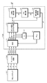
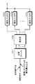
- An optical disc apparatus to which the present disclosure can be applied includes, as shown in FIG. 1, an optical pickup 101 for recording and reproducing information on an optical disc 100 as an optical recording medium, and a spindle motor 102 for rotating the optical disc 100. Prepare. In order to move the optical pickup 101 in the radial direction of the optical disc 100, a thread (feed motor) 103 is provided.
- a high density optical disc such as BD (Blu-ray (registered trademark) Disc) can be used.
- the BD is a high density optical disc having a recording capacity of about 25 GB (gigabyte) in a single-sided single layer and about 50 GB in two-sided single layer.
- the light source wavelength is set to 405 nm, and the numerical aperture NA (Numerical Aperture) of the objective lens is increased to 0.85.
- the spot diameter can be narrowed to 0.58 ⁇ m.
- BD Blu-ray (registered trademark) Disc
- the channel bit length that is, the mark length is shortened, the density is increased in the linear density direction, and 100GB in three layers and 128GB in four layers.
- BDXL registered trademark
- an optical disc adopting a method of recording data on both a groove track and a land track (referred to as a land / groove recording method as appropriate).
- the groove is referred to as a groove
- the track formed by the groove is referred to as a groove track.
- the grooves are defined as portions irradiated with laser light when an optical disc is manufactured, an area between adjacent grooves is referred to as a land, and a track formed by the land is referred to as a land track.
- the recording capacity can be further increased.
- an optical track is obtained by making the groove depth as wide as about ⁇ / 6 with a wide track pitch to the extent that ⁇ 1st order diffracted light from the grooves overlap.
- the shallow groove structure equal to or smaller than that of BD be capable of reducing crosstalk between adjacent tracks.
- optical disc 100 capable of high density recording
- it is rotationally driven at a constant linear velocity (CLV) or a constant angular velocity (CAV) by the spindle motor 102 at the time of recording / reproducing.
- CLV linear velocity
- CAV constant angular velocity
- reading of mark information recorded on a track on the optical disc 100 is performed by the optical pickup (optical head) 101.
- user data is recorded as a phase change mark or a pigment change mark on a track on the optical disc 100 by the optical pickup 101.
- phase change mark In the case of a recordable disc, a recording mark by a phase change mark is recorded on the track formed by the wobbling groove, but the phase change mark is RLL (1, 7) PP modulation method (RLL; Run Length Limited, PP) Recording is performed at a linear density of 0.12 ⁇ m / bit and 0.08 ⁇ m / channel bit in the case of 23.3 GB of BD per layer by, for example, Parity preserve / Prohibit rmtr (repeated minimum transition run length).
- optical disc 100 In the inner circumferential area of the optical disc 100, physical information of the disc, for example, is recorded as emboss pits or wobbling grooves as reproduction-only management information. Reading of these pieces of information is also performed by the optical pickup 101. Further, reading of ADIP information embedded as wobbling of a groove track on the optical disc 100 is also performed by the optical pickup 101.
- a laser diode serving as a laser light source, and an optical for separating reflected light into a plurality of signals having different bands in a line optical density direction (tangential direction) and a track density direction (radial direction) spatially optically.
- the disk recording surface is irradiated with laser light through a filter, a photodetector for detecting a plurality of signals separated by an optical filter, an objective lens serving as an output end of laser light, and an objective lens, and the reflected light is guided to a photodetector An optical system etc.
- the objective lens is held movably in the tracking direction and the focusing direction by a biaxial mechanism.
- the entire optical pickup 101 is movable by the sled mechanism 103 in the radial direction of the disc.
- the drive current from the laser driver 113 is supplied to the laser diode of the optical pickup 101, and the laser diode generates a laser.
- Reflected light from the optical disc 100 is detected by a photodetector, converted into an electrical signal according to the amount of light received, and supplied to the matrix circuit 104.
- the matrix circuit 104 is provided with a current-voltage conversion circuit, a matrix operation / amplification circuit, and the like corresponding to output currents from a plurality of light receiving elements as photodetectors, and generates necessary signals by matrix operation processing.
- the current-voltage conversion circuit and part of the matrix operation / amplification circuit may be formed in the photodetector element in consideration of the signal transmission quality. For example, a reproduction information signal (RF signal) corresponding to reproduction data, a focus error signal for servo control, a tracking error signal and the like are generated.
- a push-pull signal is generated as a signal related to groove wobbling, that is, a signal for detecting wobbling.
- the reproduction information signal output from the matrix circuit 104 is supplied to the data detection processing unit 105, the focus error signal and the tracking error signal are supplied to the optical block servo circuit 111, and the push-pull signal is supplied to the wobble signal processing circuit 106. .
- the data detection processing unit 105 performs binarization processing of the reproduction information signal. For example, the data detection processing unit 105 performs A / D conversion processing of an RF signal, reproduction clock generation processing by PLL, PR (Partial Response) equalization processing, Viterbi decoding (maximum likelihood decoding), etc. A binary data string is obtained by (PRML detection method: Partial Response Maximum Likelihood detection method). The data detection processing unit 105 supplies a binary data string as information read from the optical disc 100 to the encode / decode unit 107 in the subsequent stage.
- PRML detection method Partial Response Maximum Likelihood detection method
- the encode / decode unit 107 performs demodulation of reproduction data at the time of reproduction and modulation processing of recording data at the time of recording. That is, at the time of reproduction, data demodulation, deinterleaving, ECC decoding, address decoding and the like are performed, and at the time of recording, ECC encoding, interleaving, data modulation and the like are performed.
- the binary data string decoded by the data detection processing unit 105 is supplied to the encoding / decoding unit 107.
- the encode / decode unit 107 demodulates the binary data string to obtain reproduction data from the optical disc 100. That is, for example, demodulation processing for data recorded on the optical disc 100 with run length limited code modulation such as RLL (1, 7) PP modulation and ECC decoding processing for performing error correction is performed. Get playback data from.
- the data decoded to reproduction data by the encode / decode unit 107 is transferred to the host interface 108, and transferred to the host device 200 based on an instruction of the system controller 110.
- the host device 200 is, for example, a computer device or an AV (Audio-Visual) system device.
- processing of ADIP information is performed. That is, the push-pull signal output from the matrix circuit 104 as a signal related to groove wobbling is converted to wobble data digitized by the wobble signal processing circuit 106. PLL processing generates a clock synchronized with the push-pull signal.
- the wobble data is demodulated into a data stream constituting an ADIP address by the ADIP demodulation processing unit 116 and supplied to the address decoder 109.
- the address decoder 109 decodes the supplied data, obtains an address value, and supplies it to the system controller 110.
- recording data is transferred from the host device 200, but the recording data is supplied to the encoding / decoding unit 107 via the host interface 108.
- the encoding / decoding unit 107 performs error correction code addition (ECC encoding), interleaving, subcode addition, and the like as encoding processing of recording data.
- ECC encoding error correction code addition
- Run-length limited code modulation such as RLL (1-7) PP method is performed on the data subjected to these processes.
- the recording data processed by the encode / decode unit 107 is supplied to the write strategy unit 114.
- the write strategy unit 114 adjusts the laser drive pulse waveform with respect to the characteristics of the recording layer, the spot shape of the laser beam, the recording linear velocity, and the like as the recording compensation processing. Then, the laser drive pulse is output to the laser driver 113.
- the laser driver 113 causes a current to flow to the laser diode in the optical pickup 101 based on the laser drive pulse subjected to the recording compensation processing to emit a laser. As a result, a mark corresponding to the recording data is formed on the optical disc 100.
- the optical block servo circuit 111 generates various servo drive signals of focus, tracking, and sled from the focus error signal and the tracking error signal from the matrix circuit 104 to execute the servo operation. That is, the focus drive signal and the tracking drive signal are generated according to the focus error signal and the tracking error signal, and the driver 118 drives the focus coil and the tracking coil of the biaxial mechanism in the optical pickup 101. As a result, the optical pickup 101, the matrix circuit 104, the optical block servo circuit 111, the driver 118, and the tracking servo loop and the focus servo loop by the biaxial mechanism are formed.
- the optical block servo circuit 111 turns off the tracking servo loop in response to the track jump command from the system controller 110 and outputs a jump drive signal to execute a track jump operation. Furthermore, the optical block servo circuit 111 generates a thread drive signal based on a thread error signal obtained as a low-frequency component of the tracking error signal, access execution control from the system controller 110, etc. Drive.
- the spindle servo circuit 112 controls the spindle motor 102 to perform CLV rotation or CAV rotation.
- the spindle servo circuit 112 obtains a clock generated by the PLL for the wobble signal as rotational speed information of the present spindle motor 102, and generates a spindle error signal by comparing this with predetermined reference speed information. Further, at the time of data reproduction, since the reproduction clock generated by the PLL in the data detection processing unit 105 becomes the current rotational speed information of the spindle motor 102, the spindle is compared with predetermined reference speed information. An error signal is generated. The spindle servo circuit 112 outputs a spindle drive signal generated according to the spindle error signal, and causes the spindle driver 117 to execute CLV rotation or CAV rotation of the spindle motor 102.
- the spindle servo circuit 112 generates a spindle drive signal in accordance with a spindle kick / brake control signal from the system controller 110, and also performs operations such as start, stop, acceleration, and deceleration of the spindle motor 102.
- the various operations of the servo system and the recording and reproducing system as described above are controlled by a system controller 110 formed by a microcomputer.
- the system controller 110 executes various processing in response to a command from the host device 200 given via the host interface 108. For example, when a write command (write command) is issued from the host device 200, the system controller 110 first moves the optical pickup 101 to an address to be written. Then, the encoding / decoding unit 107 causes the encoding process to be performed on the data (for example, video data, audio data, etc.) transferred from the host device 200 as described above. Then, recording is performed by the laser driver 113 driving laser light emission according to the encoded data.
- a write command write command
- the system controller 110 first moves the optical pickup 101 to an address to be written.
- the encoding / decoding unit 107 causes the encoding process to be performed on the data (for example, video data, audio data, etc.) transferred from the host device 200 as described above.
- recording is performed by the
- the system controller 110 when a read command for transferring certain data recorded on the optical disc 100 is supplied from the host device 200, the system controller 110 first performs seek operation control for the designated address. That is, a command is issued to the optical block servo circuit 111, and the access operation of the optical pickup 101 with the address specified by the seek command as the target is executed. Thereafter, operation control necessary to transfer data of the instructed data section to the host device 200 is performed. That is, data reading from the optical disc 100 is performed, reproduction processing in the data detection processing unit 105 and the encoding / decoding unit 107 is executed, and requested data is transferred.
- FIG. 1 has been described as an optical disc apparatus connected to the host device 200, the optical disc apparatus may have a form not connected to another apparatus.
- the operation unit and the display unit are provided, and the configuration of the data input / output interface portion is different from that in FIG. That is, recording and reproduction may be performed according to the user's operation, and a terminal portion for input / output of various data may be formed.
- the optical disk apparatus there are various other possible configuration examples of the optical disk apparatus.
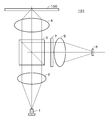
- the optical pickup 101 uses, for example, a laser beam (beam) having a wavelength ⁇ of 405 nm to record information on the optical disc 100 and reproduce information from the optical disc 100.
- Laser light is emitted from a semiconductor laser (LD: Laser Diode) 1.
- a laser beam passes through a collimator lens 2, a polarizing beam splitter (PBS) 3, and an objective lens 4, and is irradiated onto the optical disc 100.
- the polarization beam splitter 3 has, for example, a separation surface that transmits approximately 100% of P-polarized light and reflects approximately 100% of S-polarized light. Reflected light from the recording layer of the optical disc 100 returns along the same optical path and enters the polarization beam splitter 3. By interposing a ⁇ / 4 element (not shown), the incident laser light is reflected approximately 100% by the polarization beam splitter 3.
- the laser beam reflected by the polarization beam splitter 3 is spatially optically optically linear density direction and track density direction by a dividing line extending in the radial direction (disk radial direction) and tangential direction (track direction) of the optical disk 100 by the optical filter 7
- the light is divided into a plurality of regions including signals in different bands, and condensed on the light receiving surface of the photodetector 6 through the lens 5.
- the area of the optical filter 7 is divided.
- the photodetector 6 has a light receiving cell on the light receiving surface for photoelectrically converting the incident light.
- the light receiving cells are arranged to respectively receive the light divided into a plurality of regions by the optical filter 7.
- the photodetector 6 outputs electrical signals of a plurality of channels in accordance with the amount of light received in each region of the light receiving cell.
- the optical filter 7 spatially splits the light flux into four regions including different-band signals in the line density direction and the track density direction.
- the respective signals of the four regions are denoted A, C, E and F.
- the notation of the area and the reproduction signal obtained from the area are indicated by the same reference numerals.
- the light reception signal is calculated by the matrix circuit 104 to generate four channels of signals Ch 1 to Ch 4, and the four channels of signals Ch 1 to Ch 4 are input to the data detection processing unit 105.
- the configuration of the optical pickup 101 in FIG. 2 shows the minimum components for explaining the present disclosure, and a focus error signal and a tracking error output to the optical block servo circuit 111 via the matrix circuit 104.
- a signal, a signal for generating a push-pull signal output to the wobble signal processing circuit 106 through the matrix circuit 104, and the like are omitted.
- various configurations other than the configuration shown in FIG. 2 are possible.
- the cross section of the light beam of the return beam from the optical disc 100 is divided into a plurality of areas, and reproduction signals of a plurality of channels corresponding to each area are obtained.
- a method of obtaining the reproduction information signal for each area other than the method of dividing by the optical filter 7, a method of dividing the photodetector 6 to give the photodetector an optical filter function can also be used.
- a plurality of optical path conversion elements for separating a plurality of regions are disposed in the optical path passing through the objective lens 4 to the photodetector 6, and a plurality of optical path conversion elements separated Can be used to supply different beams to different photodetectors, and as the optical path conversion element, a diffractive element such as a holographic optical element, or a refractive element such as a microlens array or a microprism can be used. .
- the optical pickup 101 reproduces from the optical disc 100, detection signals corresponding to the respective regions are supplied to the matrix circuit 104, and the signals of the plurality of channels are made equal in number to the signals before calculation.
- the data detection processing unit 105 has an A / D converter 11 to which the reproduction information signal supplied from the matrix circuit 104 is supplied as shown in FIG.
- FIGS. 3 and 4 show an example in which the cross section of the light beam of the return beam from the optical disk 100 is divided into four areas, and the four-channel reproduction signals Ch1 to Ch4 are obtained from the matrix circuit 104.
- a clock for the A / D converter 11 is formed by the PLL 12.
- the reproduction signal supplied from the matrix circuit 104 is converted into digital data by the A / D converter 11.
- the reproduction information signals are referred to as S1 to S4 in which the reproduction signals Ch1 to Ch4 of four channels generated by the matrix circuit 104 are digitized.
- a signal obtained by adding the reproduction information signals S1 to S4 by the addition circuit 17 is supplied to the PLL 12.
- the data detection processing unit 105 includes a multi-input adaptive equalizer unit 13, a binarization detector 14, a PR convolution unit 15, and an equalization error computing unit 16.
- the multi-input adaptive equalizer unit 13 performs PR adaptive equalization processing based on the reproduction information signals S1 to S4. That is, the reproduction information signals S1 to S4 are output through the adaptive equalizer unit and equalized so that the equalized signal y0 added is approximated to the target PR waveform.
- the output of the multi-input adaptive equalizer unit may be used as a signal input to the PLL 12.
- the initial coefficient of the multi-input adaptive equalizer is set to a predetermined value.
- the frequency characteristics of the phase and the amplitude of the reproduction information signals S1 to S4 are changed by an FIR filter or the like instead of simply adding the reproduction information signals S1 to S4. It is good also as composition which adds by.
- the tap coefficient of the FIR filter is set to a predetermined value.
- the binarization detector 14 is, for example, a Viterbi decoder, and maximum likelihood decoding processing is performed on the PR equalized equalization signal y0 to obtain binarized data DT.
- the binarized data DT is supplied to the encode / decode unit 107 shown in FIG. 1 to perform reproduction data demodulation processing.
- the Viterbi decoding uses a Viterbi detector composed of a plurality of states composed of consecutive bits of a predetermined length and a branch represented by a transition between them, and uses all possible bit sequences. Among them, the configuration is configured to efficiently detect a desired bit sequence.
- a register for storing partial response series up to the state called path metric register and path metric of the signal, and a flow of bit series up to the state called path memory register Two registers of registers for storing are provided. Furthermore, for each branch, there is provided an operation unit called branch metric unit that calculates a partial response sequence at that bit and a path metric of the signal.
- various bit sequences can be associated in a one-to-one relationship by one of the paths passing through the state.
- the path metric between the partial response sequence passing through these paths and the actual signal (reproduction signal) is the inter-state transition constituting the above path, that is, the above-mentioned branch metric in the branch It is obtained by adding.
- the PR convolver 15 performs a convolution process of the binarization result to generate a target signal Zk, as shown in the following equation.
- the target signal Zk is an ideal signal without noise because it is a convolution of the binary detection result.
- PR (1, 2, 2, 2, 1) the value P for each channel clock is (1, 2, 2, 2, 1).
- the restraint length is five.
- PR (1, 2, 3, 3, 3, 2, 1) the value P for each channel clock is (1, 2, 3, 3, 3, 2, 1).
- the restraint length is seven.
- PR (1, 2, 3, 4, 4, 4, 3, 2, 1) the value P for each channel clock is (1, 2, 3, 4, 4, 3, 2, 1) ).
- the restraint length is nine.
- the partial response constraint length If the detection capability is not increased by increasing the length from 5 to 7, detection will be difficult, and if the recording density is increased to about 45 GB, the constraint length is increased to 7 to 9 to increase detection capability. There is a need to.
- d represents binarized data.
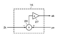
- the equalization error computing unit 16 obtains an equalization error ek from the equalization signal y0 from the multi-input adaptive equalizer unit 13 and the target signal Zk, and controls the tap coefficient of the equalization error ek to the multi-input adaptive equalizer unit 13. Supply for.
- the equalization error calculator 16 includes a subtractor 26 and a coefficient multiplier 27.
- the subtractor 26 subtracts the target signal Zk from the equalized signal y0.
- An equalization error ek is generated by multiplying the subtraction result by a predetermined coefficient a by the coefficient multiplier 27.
- the multi-input adaptive equalizer unit 13 includes adaptive equalizer units 21, 22, 23, 24 and an adder 25.
- the reproduction information signals S1 to S4 described above are inputted to the adaptive equalizer units 21 to 24, respectively.
- the configuration of the multi-input adaptive equalizer unit 13 is shown when the reproduction information signal output from the matrix circuit has four channels.
- An adaptive equalizer unit is provided corresponding to the number of channels of the input signal.
- Each of the adaptive equalizer units 21, 22, 23, 24 has parameters of the number of FIR (Finite Impulse Response) filter taps, the calculation accuracy (bit resolution), and the update gain of the adaptive calculation, and an optimum value is set for each. ing.
- An equalization error ek is supplied to each of the adaptive equalizer units 21, 22, 23, 24 as a coefficient control value for adaptive control.
- the outputs y 1, y 2, y 3, y 4 of the adaptive equalizer units 21, 22, 23, 24 are added by the adder 25 and output as the equalized signal y 0 of the multi-input adaptive equalizer unit 13.
- An output target of the multi-input adaptive equalizer unit 13 is an ideal PR waveform in which a binary detection result is convoluted into PR (partial response).
- the adaptive equalizer unit 21 is composed of, for example, an FIR filter as shown in FIG.
- the adaptive equalizer unit 21 is a filter having taps of n + 1 stages including delay elements 30-1 to 30-n, coefficient multipliers 31-0 to 31-n, and an adder.
- the coefficient multipliers 31-0 to 31-n multiply tap coefficients C0 to Cn with respect to the input x at each point in time.
- the outputs of the coefficient multipliers 31-0 to 31-n are added by the adder 34 and taken out as the output y0.
- the tap coefficient is set in advance to an initial value.
- Control of tap coefficients C0 to Cn is performed in order to perform adaptive equalization processing.
- arithmetic units 32-0 to 32-n are provided which are input with equalization errors ek and respective tap inputs.
- integrators 33-0 to 33-n that integrate the outputs of the computing units 32-0 to 32-n are provided.
- Each of the arithmetic units 32-0 to 32-n performs, for example, an operation of -1 * ek * x.
- the outputs of the arithmetic units 32-0 to 32-n are integrated by the integrators 33-0 to 33-n, and the tap coefficients C0 to Cn of the coefficient multipliers 31-0 to 31-n are changed and controlled by the integration result. Ru.
- the integration of the integrators 33-0 to 33-n is performed to adjust the response of the adaptive coefficient control.
- decoding of binarized data is performed after unnecessary signals such as crosstalk are reduced.
- the adaptive equalizer units 22, 23 and 24 also have the same configuration as the adaptive equalizer unit 21.
- a common equalization error ek is supplied to the adaptive equalizer units 21, 22, 23, 24 to perform adaptive equalization. That is, in the adaptive equalizer units 21, 22, 23, 24, the error of the input signal frequency component of the reproduction information signals Sa, Sb, Sc and the phase distortion are optimized, that is, adaptive PR equalization is performed. That is, the tap coefficients C0 to Cn are adjusted in accordance with the calculation result of ⁇ 1 * ek * x in the arithmetic units 32-0 to 32-n. This means that the tap coefficients C0 to Cn are adjusted in the direction of eliminating the equalization error.
- the tap coefficients C0 to Cn are adaptively controlled in the direction to achieve the target frequency characteristics using the equalization error ek.
- the equalization signal y0 of the multi-input adaptive equalizer unit 13 obtained by adding the outputs y1, y2, y3, y4 of the adaptive equalizer units 21, 22, 23, 24 by the adder 25 has crosstalk, intersymbol interference, etc. It is a reduced signal.
- Electro-optical filter The signal reproduced from the optical disc is ideal for the ideal signal, due to the increase in intersymbol interference due to the linear densification and the increase in the signal leakage from the adjacent track due to the track densification. It is a big departure from the signal. In the past, electrical filters have solved this problem. For example, 33.4 GB / L is realized in BDXL (registered trademark).
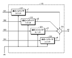
- FIG. 1 An arrangement for reproducing a high density recorded signal according to the present disclosure is as shown in FIG. That is, the reproduction signal is supplied to the optical filter 131, and the optical filter 131 generates a plurality of, for example, n first signals having different bands in the line density direction (tangential direction) and the track density direction (radial direction) spatially optically. Separate into x11, x12, ----, x1 n. The separated n first signals x 11, x 12,..., X 1 n are supplied to the calculation unit 132. The computing unit 132 computes the first signals x11, x12, ----, x1 n to form n second signals x21, x22, ----, x2 n.
- the second signals x21, x22,..., X2 n are supplied to the electric filters 133 1 to 133 n .
- the reproduction signal is obtained by summing the outputs of the electric filters 133 1 to 133 n . As this calculation, the following can be considered.
- the luminous flux is split into Reproduction information signals of a plurality of channels are formed using a plurality of light reception signals corresponding to the amounts of light respectively incident on the plurality of regions, and are respectively supplied to the electric filter.
- the above-mentioned adaptive equalizer unit corresponds to an electric filter.
- the matrix circuit 104 performs part of the function of the optical filter by receiving the signal lights divided into the areas by separate light receiving elements and performing calculations.
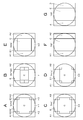
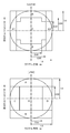
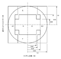
- the circle in the figure indicates the outer periphery of the cross section of the beam.
- Squares are, for example, diffraction elements such as holographic optical elements for separating a plurality of regions, optical path conversion elements including microlens elements, refractive elements such as micro prisms, etc. It represents the area of the light receiving cell.
- the vertical direction of the region division diagram corresponds to the tangential direction of the returned light flux, and the horizontal direction corresponds to the radial direction.
- the area division pattern shown in FIG. 8 is an example, and patterns other than those shown in FIG. 8 are also possible.
- the dividing line is not limited to a straight line, and may be a curved line such as an arc.
- the region division position in the radial direction is set to be ⁇ 0.5 and ⁇ 0.7 when the pupil radius is 1.0.
- the region division position in the tangential direction is ⁇ 0.45 and ⁇ 0.65 when the pupil radius is 1.0.
- the four channel signals corresponding to the division pattern of IVT 4 may be generated based on the outputs from the four light receiving cells respectively corresponding to the above regions A, C, E and F.
- C, E, F may be used to generate four channels of signals using matrix circuits based on outputs from five light receiving cells corresponding to the five regions.
- various division patterns as described below can be realized with the same division as a basic form.
- the pattern shown in FIG. 8B is obtained by changing the shape and arrangement of each region so as to improve the characteristics at a higher linear density while following the optical filter configuration of IVT4.
- the pattern shown in FIG. 8C is a combination of channels (E and F) outside IVT 4 into one channel E.
- the pattern IV3ts0.2 shown in FIG. 8D is a pattern in which IV3 is shifted in the tangential direction, for example, 20% of the luminous flux radius.
- Three channel signals corresponding to three regions are obtained.
- Patterns R2 and R3 are comparative patterns to clarify the effects of the configuration of the present disclosure.
- a pattern R2 which divides the beam into two in the radial direction and a pattern R3 which divides it into three in the radial direction are shown by two dividing lines which extend the beam in the tangential direction.
- the electrical signals corresponding to the light reception signals in the regions A1 and A2 are added to be a signal of one channel. That is, two channels (R2) of the inner channel (region C) and the outer channel (region A1 + A2) are formed.
- the region division position in the radial direction is a position that is ⁇ 0.55 when the pupil radius is 1.0.
- the results of comparison of characteristics when the techniques of Patent Documents 2 and 3 and the PRML detection method are combined will be described later.
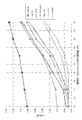
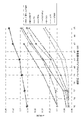
- FIG. 9 shows simulation results for the six patterns shown in FIG. The same applies to the following simulations, but using e-MLSE as a signal index value.
- e-MLSE a signal evaluation value different from i-MLSE, to which a new data pattern is added, which is necessary to improve the accuracy of the signal index value at a higher linear density, is used to explain the effect.
- e-MLSE a new index value with improved accuracy
- the data patterns added in e-MLSE are the following three types.
- the bit in which 1 of the pattern sequence is written indicates the position where bit inversion occurs in the error pattern with respect to the detection pattern.
- e-MLSE and i-MLSE almost match at the same linear density as the conventional BDXL (registered trademark) where the accuracy of i-MLSE is sufficient, and the difference of error improvement appears at higher linear density.
- the theoretical correlation between the index values and the error rate, which is important in practical use, is the same for both. Therefore, although there is a difference in calculation and a difference in the range of applied linear density, the evaluation values of the signal quality indicated by both may be taken in the same sense.
- an index other than e-MLSE may be used. The difference between e-MLSE and i-MLSE due to differences in data patterns that are prone to errors when the linear density increases will be supplemented later.
- a graph represented as e-MLSE is a result in the case where region segmentation is not performed.
- the e-MLSE has not been sufficiently lowered with LD 35 GB.
- R2 and R3 have almost the same characteristics at the perturbation origin.
- H3A and IV3 can reduce the e-MLSE in the LD35GB, the degradation due to the high linear density is large because there is no channel whose central position is different in the tangential direction.
- H3A has a slightly higher e-MLSE even in the LD 35 GB, and the difference expands as the linear density increases.
- the pattern IV3ts0.2 in which the pattern of IV3 is shifted in the tangential direction can differentiate the central position when the outer channel in the tangential direction and the central channel are considered at the center of gravity, so degradation due to high linear density It is possible to suppress a little.
- IVT4 with a channel whose center position is different in the tangential direction has linear density for IV3 in which the radial and tangential division positions are the same, in addition to the fact that e-MLSE at LD 35 GB can be sufficiently reduced. It can be seen that there is a high linear density effect equivalent to LD 3 GB in the direction.
- the IVT 4 H in which the shape of the optical filter is optimized by giving priority to the characteristics at the time of the high linear density has a high linear density effect equivalent to the LD 1 GB with respect to the IVT 4.
- Patent Document 2 suggests that “it is possible to emphasize and reproduce the reproduction signal of a small recording mark by weighting also in the beam traveling direction”, and thus the e-MLSE improvement effect
- LD39GB in which H has decreased
- the result of further dividing the central region at the position corresponding to H3A and further weighting twice on the outer side and the inner side in the tangential direction is LD39GB, There is almost no high linear density effect as suggested.
- FIG. 11 which accumulated and plotted the result by the application example which combined the technique of these patent documents 2 and 3 and the PRML detection system, and also changed the weighting coefficient by linear density on the graph of FIG.
- the superiority of the bottom property in the LD35GB of the configuration of the present disclosure and the further superiority of IVT4 and IVT4H when the linear density is increased are clearly shown.
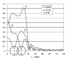
- FIG. 12 shows tap coefficients in simulation results in the case of LD 35 GB of the FIR filter in the configuration of the above patent document application and the FIR filter in pattern R 2 and the corresponding frequency amplitude characteristics as an electric filter. Shown in.
- the characteristic L1 in the case of the pattern R2 is the frequency amplitude characteristic of the channel corresponding to the outer region A, and the characteristic L2 is the frequency amplitude characteristic of the channel corresponding to the inner region C.
- the horizontal axis is n / (256T) (n: value on the horizontal axis).
- n 64
- (64 / 256T) (1 / 4T).
- the mark length is from 2T to 8T, where the channel clock cycle is "T”.
- (1 / 4T) is a frequency when the 2T mark repeats. In the LD 35 GB, since the 2T mark exceeds the spatial optical cutoff frequency, it is in a frequency range that can not be reproduced, and the 3T mark can be reproduced.
- the region is further divided in the tangential direction in addition to the radial direction, and divided into three regions corresponding to the signals having different bands in the linear density direction and the track density direction in space optical direction.
- the adaptive electro-optical filter characteristic of the LD 35 GB in the pattern H3A is shown in FIG.
- the horizontal axis is n / (256T) (n: value on the horizontal axis).
- n 64
- (64 / 256T) (1 / 4T).
- the mark length is from 2T to 8T, where the channel clock cycle is "T”.
- (1 / 4T) is a frequency when the 2T mark repeats.
- the characteristic L1 is the frequency amplitude characteristic of the channel corresponding to the region A in the radial direction
- the characteristic L2 is the frequency amplitude characteristic of the channel corresponding to the region E in the tangential direction
- the characteristic L3 is the central region It is a frequency amplitude characteristic of a channel corresponding to C.
- the characteristic is an example of the characteristic at the perturbation origin.
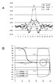
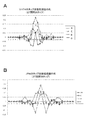
- FIG. 14A shows tap coefficients of respective channels of the pattern H3A.
- the number of taps of the FIR filter is 31.
- FIG. 14B shows the frequency phase characteristics of each channel.
- the frequency phase characteristic represents the phase difference between two of the three channels.
- a characteristic L11 is a phase difference between reproduction information signals of channels corresponding to the region E on the outer side in the tangential direction and the region A on the outer side in the radial direction.
- a characteristic L12 is a phase difference between reproduction information signals of channels corresponding to the central region C and the radial outer region A, respectively.
- a characteristic L13 is a phase difference between reproduction information signals of channels corresponding respectively to the region E outside the tangential direction and the region C at the center.
- the filter characteristics of H3A have the following features.
- a filter having frequency characteristics that greatly differ in both amplitude and phase for each of the three channel regions can be configured to realize good reproduction signal reproduction.
- the phases are shifted by 180 degrees between the central region and the region E outside the tangential direction and the region A outside the radial direction.
- the central region has a characteristic of blocking a frequency band (near the value 32 of the horizontal axis) corresponding to the 4T signal, and suppresses spurious signals due to crosstalk.
- the tangential direction outer side should contribute to the short mark reproduction, and cuts off the frequency band corresponding to the 8T signal (near the value 16 of the horizontal axis), and in the lower frequency band than the 8T signal, the central region C
- the phase is shifted by 180 degrees between the region A on the radially outer side and the region E on the outer side in the tangential direction.
- a high pass filter, a low pass filter, a band pass filter, a band stop (or notch) filter, and the like are configured for each region, and filter characteristics that can not be realized by only optics or only electricity are realized.
- the tap coefficients of the adaptive equalizer unit are adaptively controlled.
- the adaptive type is excellent in terms of performance, it is possible to simplify processing and hardware since it is preferable because adaptive control of tap coefficients is not performed. Further, it is also possible to use a fixed type equalizer unit for some of the plurality of channels and use an adaptive equalizer unit for the other channels.
- IVT 4 has very good e-MLSE characteristics in LD 35 GB, and also patterns R 3 and H 3 A in which the central position in the tangential direction does not have different channels even when the linear density is increased. Compared to IV3, e-MLSE can be maintained in good condition.
- the tap coefficient of each channel corresponding to each region (in this case, the number of taps of the FIR filter is 31 taps) is shown in FIG. 16A in the case of LD 35 GB, and the frequency amplitude characteristic is shown in FIG. It is shown in FIG. 16B.
- the frequency phase characteristic represents the phase difference between the channel corresponding to the region E outside the tangential direction and the channel corresponding to the region F outside the tangential direction.
- the filter characteristic of IVT 4 shown in FIG. 15 and FIG. 16 has the following characteristics. Similar to the pattern H3A, the central region has low-pass characteristics and the tangential direction outer region has high-pass characteristics (in this case, high-pass characteristics are shorter in the frequency band contributing to signal reproduction) The band pass characteristic passing through the band corresponding to the mark is expressed as a relatively high-pass type).
- the outer region in the tangential direction is independently two channels, and the two regions are about 120 to 90 degrees in the frequency band corresponding to 3T and 4T (near the values of 43 and 32 in the horizontal axis)
- the filter is configured to have a phase difference of (about 2 clocks, as can be seen from the tap coefficients). This enables more sensitive detection of the short mark with respect to the reproduction amplitude by the simple sum signal. With regard to the short mark reproduction, by utilizing the phase difference between the regions, not only a good reproduction signal characteristic is realized, but also it contributes to a good characteristic when the linear density is further increased.
- the graph represented as e-MLSE is the result in the case where region segmentation is not performed.
- IV3 which does not have a channel whose center position is different in the tangential direction is degraded by the higher linear density. large.
- the IVT 4 having channels whose center positions are different in the tangential direction has a high linear density effect equivalent to LD 3 GB in the linear density direction with respect to IV 3 where the division positions in the radial and tangential directions are the same.
- IVT 4 H in which the shape of the optical filter is optimized by giving priority to the characteristics at the time of high linear density can also obtain the high linear density effect equivalent to LD 1 GB with respect to IVT 4.
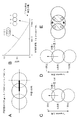
- the optical disc can be increased in density by increasing the density in the track density direction.
- recording marks are two-dimensionally arranged on the signal recording surface.
- the reproduction signal in the optical disc detects a change in light and dark caused by interference of diffracted lights generated by periodic structures such as recording marks and grooves.
- the shift amount of the center is represented by ⁇ / (NA * p)
- the ⁇ 1st order diffracted light due to the periodic structure of period p is reproduced as the overlap is larger.
- the amplitude of the signal increases, and the smaller the overlap, the smaller the amplitude.
- MTF Modulation Transfer Function
- the region outside the tangential direction is a filter that high-passes the frequency band corresponding to short marks such as 3T and 4T, and the central region Is a low-pass filter that passes many frequency bands corresponding to long marks of 5T or more.
- this corresponds to the region to which more contribution is given to the reproduction of the band corresponding to the spatially optically short mark and the reproduction of the band corresponding to the long mark.
- the regions are divided in the tangential direction and the radial direction, and high pass filters are provided to the signals from the respective regions.
- the diffracted light corresponding to the short mark reproduction corresponding to the short mark reproduction is not only the signal of the 0th-order light region but also the interference region with the ⁇ 1st-order diffracted light according to the track structure It is effective to separate the signals in the region of
- the radially outer area (A1, A2) is sensitive to noise because it has high gain over a wide band. Furthermore, having a channel outside in the tangential direction is advantageous for higher linear density.
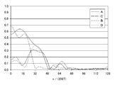
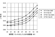
- FIG. 19 is a simulation result showing the influence of random noise represented by amplifier noise.
- PRML of PR (1233321) is used.
- Simulation results for IVT4 and IVT4H are shown.
- the relationship between IVT4 (Na + 0) and IVT4 (Na + 3 dB) means that random noise represented by amplifier noise is increased by 3 dB.
- IVT4H (Na + 0) and IVT4H (Na + 3 dB) have the same meaning.
- FIG. 20 is a simulation result showing the influence of random noise represented by amplifier noise.
- PRML of PR (123444321) is used. Simulation results for IVT4 and IVT4H are shown. Also in this case, the same as described above is shown.
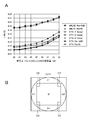
- FIG. 21A is a simulation result showing the influence of random noise represented by amplifier noise.
- PRML of PR (123444321) is used.
- Simulation results for IVT 4 are shown.
- random noise other than amplifier noise is sufficiently small, and the effect of assuming that amplifier noise is dominant as random noise is shown.
- (R 2 amp) shows the case where the radially outer channels A 1 and A 2 are received by different detectors, and are added via an IV amplifier.
- the use of two IV amplifiers increases amplifier noise.
- (T 2 amp) indicates the case where channel E or F on one side in the tangential direction uses two amplifiers
- C 2 amp indicates the case where the central channel uses two amplifiers.
- (Na + 3 dB) shows the case where all four channels use two amplifiers.
- FIG. 22 is a simulation result to show the influence of amplifier noise.
- PRML of PR (123444321) is used.
- Simulation results for IVT 4H are shown.
- FIG. 22A the meanings of (R 2 amp), (T 2 amp), (C 2 amp) and (Na + 3 dB) are the same as in FIG. 21A.
- the value of e-MLSE is degraded by 1 to 2% (0.01 to 0.02) by the increase of amplifier noise or the decrease of the signal amount, so the amplifier noise is reduced and the recording signal is degraded. It is important to design the reflectivity of the disc, which can ensure sufficient reproduction power within a range that does not cause this problem and ensure a sufficient amount of signal.
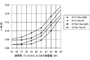
- the linear density range of LD35GB to LD45GB is PR (1,2,3,3,3,2,1) with a constraint length of 7, and the linear density range of LD39GB to LD55GB is a constraint length of 9
- the simulation results are shown by fixing to PR (1, 2, 3, 4, 4, 4, 3, 2, 1).
- the best PR class is different depending on the type.
- PR class The frequency characteristics of the adaptive equalization target for the optical filters and various PR classes considered to be effective for the signal recording density assumed in the present disclosure are indicated by the horizontal axis n / (256T) as with the electric filters. It is shown in FIG. It is effective to use the value PR-TL (4T) of the equalization target (target level) at the frequency corresponding to the horizontal axis 32, that is, the 4T mark / space, as an index value characterizing the characteristics of each PR class.
- PR-TL (4T) of the equalization target (target level) at the frequency corresponding to the horizontal axis 32, that is, the 4T mark / space
- a disc with a single-sided three-layer structure is prepared and recorded with a plurality of signal recording densities, but not configured or provided with an optical filter having channels corresponding to a plurality of areas having different center positions in the tangential direction.
- the results of signal regeneration using an arrangement having an optical filter are shown below.
- Disc recording surface single-sided three-layer structure Tp 0.225 ⁇ m (land and groove respectively) Groove depth approx. (1/16) ⁇
- Multi-track recording and reproduction optical system NA 0.85 wavelength 405 nm equivalent to 351 GB LD 47.0 GB (39.7 nm / channelbit) 66.8 GB / layer, equivalent to 401 GB with 6 layers on both sides
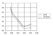
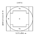
- Optical filter Two types VHT4 shown in FIG. 24 total 4 of 3 channels corresponding to 3 regions C, E, F different in center position in the tangential direction and 1 channel corresponding to the region A (A1 + A2) on the radially outer side The signal of the channel is obtained. It is an optical filter having characteristics very close to the above-mentioned IVT4. A representative example of the type "T-type" having a plurality of regions having different center positions in the tangential direction is used. JR 4: There is no channel corresponding to a plurality of areas with different center positions in the tangential direction.
- a total of four channels of signals are obtained: three channels corresponding to three regions C, E, D having different central positions in the radial direction and one channel corresponding to the region (A + B) outside the tangential direction.
- a representative example of the type "R-type" having a plurality of regions having different central positions in the radial direction is used.
- FIG. 26 shows experimental results in the case of 300 GB equivalent with LD 35.18 GB (53 nm / channel bit) 50.0 GB / layer, 6 layers on both sides.
- FIG. 27 shows an experimental result in the case of LD 41.1 GB (45.4 nm / channel bit) 58.5 GB / layer, equivalent to 351 GB with 6 layers on both sides.
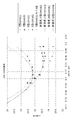
- FIG. 28 shows experimental results in the case of equivalent to 401 GB with 66.8 GB / layer, 6 layers on both sides of LD 47.0 GB (39.7 nm / channel bit).
- the horizontal axis is the equalization target value PR-TL (4T) at the frequency corresponding to 4T mark / space of the PR class used for reproduction, and the vertical axis is the average value of e-MLSE in a sufficiently wide section at that time. Shown (in percent).
- PR-TL 4T
- the vertical axis is the average value of e-MLSE in a sufficiently wide section at that time. Shown (in percent).
- T-type correspond to those described with R-type when JR4 is used
- (G) is the groove reproduction in the area where both land and groove are recorded
- (L) shows the time of land regeneration.
- PR-TL (4T) close to PR (1, 1, 2, 2, 2, 1, 1) in both land and groove in the case of R-type JR 4 in LD 35. 18 GB Is the best at 0.325 to 0.33, and in the case of T-type VHT4, the e-MLSE characteristics become almost flat at PR-TL (4T) of 0.41 or more for both land and groove. There is.
- the optimal PR class differs between the R type and the T type.
- the R-type optimum PR-TL (4T) is smaller than the T-type optimum PR-TL. It can also be seen that (4T) is on the large side, and that it is a valid PR class for comparison with fixed PR.
- the land of R-type JR 4 is PR (2, 3, 5, 7, 7, 7, 5, 3, 2) and the groove is PR (4, 5 E-MLSE is best for 7, 11, 15, 17, 15, 11, 7, 4), and the T-type VHT4 land is PR (2, 6, 8, 11, 14, 11, 8, 6, 2), the groove is the best e-MLSE per PR (1, 3, 4, 6, 7, 6, 4, 3, 1).
- the optimum PR class differs between R-type and T-type, the optimum PR class also differs between land and groove.
- the optimum PR-TL (4T at LD 41.1 GB) The best PR-TL (4T) for LD 47.0 GB is on the small side on both the R and T types, while the R and T types on the small side are reasonable PR classes for comparison with PR fixation I understand that.
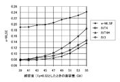
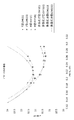
- FIG. 29 plots the relationship between the optimum PR-TL (4T) and the linear density for each of the R-type and T-type land and groove conditions. Since the PR-TL (4T) which is the best e-MLSE has a high correlation with the linear density, the relationship between the linear density at which the optimal PR-TL (4T) becomes equal between R and T types can be read from the graph It corresponds to approximately LD 3 GB, and it can be seen that an effect equivalent to the T-type high linear density effect confirmed in the simulation in which PR is fixed can be confirmed in the experiment.
- the reproduction characteristics may be checked for a plurality of PR classes corresponding to different PR-TL (4T) as candidates, and the PR class closest to the margin center with respect to PR-TL (4T) may be selected.
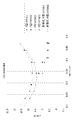
- FIG. 30 shows the relationship between the e-MLSE and i-MLSE and the linear density when the optimum PR class is selected.
- the relationship between the linear density and the e-MLSE changes linearly with almost the same slope in both R type and T type.
- e-MLSE and i-MLSE have almost the same value for both R and T types in LD 35. 18 GB, the difference between e-MLSE and i-MLSE as the linear density is increased.
- the linear density is increased, the data pattern that is likely to cause errors changes, so the difference between the e-MLSE adding the pattern and the i-MLSE not adding the pattern increases. Due to
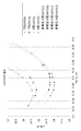
- FIG. 31 shows an e-MLSE added to FIG. 28 when the reproduction power is increased by 1.4 times with respect to the groove of T-type VHT4 in LD 41.1 GB. It can be seen that e-MLSE improves by nearly 1% by increasing the reproduction power by 1.4. Also, the optimum PR class (PR-TL (4T)) slightly changes depending on the reproduction power.
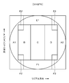
- FIG. 32 illustrates an example of a division pattern according to an embodiment of the present disclosure. It divides
- the detection signals of the respective regions of the division pattern of FIG. 32 are combined by the pattern of the selected combination (hereinafter, appropriately referred to as a selection pattern) to form four channels Ch1 as follows.
- a selection pattern for example, selection patterns IVT4M, IVR4M, IVL4M are formed.
- detection signals of detectors of each channel are synthesized according to Table 2.
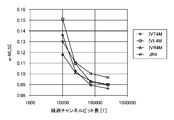
- FIG. 33 shows simulation results in the case where the linear density is LD 35.18 GB (50 GB / L) and the PR class is PR (1233321).
- the convergence difference can be absorbed to some extent, but if the quality of the disk is poor and there is a lot of signal disturbance that hinders the convergence, the convergence difference is average. It will be reflected in the difference of the characteristics.
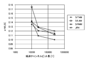
- FIG. 34 shows simulation results when the linear density and the PR class are changed.
- 34 shows simulation results for a linear density of (LD 44 GB (62.5 GB / L) and a PR class of PR (235777532). The tendency of each pattern is the same as in FIG.
- the characteristics of the IVT 4M ie T-type, are more pronounced, and depending on the linear density and the quality of the disk etc., a superior pattern can be obtained among the patterns that can be realized from the same divided pattern. It turns out that it changes.
- This IVNST 6 is obtained by further dividing the central region B into three in the radial direction in order to increase the number of divisions of the region different in band spatially in the radial direction based on the IVT 4.
- the region division position in the radial direction is a position where ⁇ 0.25, ⁇ 0.5, and ⁇ 0.7 when the pupil radius is 1.0, and the region division position in the tangential direction is ⁇ 0.45, ⁇ 0.65.
- IVTSM4, IVSP4, IVos4, and IVR4 area A is another channel on the left and right sides
- IVT4 described above Configuration
- OEIC it is possible to switch the voltage applied to the mode switching pin as three values of high level, mid level and low level.
- IVTSP5 and IVNS5 can be switched similarly.
- the “adaptive electro-optical multi-function filter (AERO) multi function filter” can improve the reproduction characteristics.
- the present disclosure reduces the influence of disturbances such as defects by performing an operation on the signal between the regions in the prior step of adaptive equalization in such a technique as described with reference to FIG. The quality is good.
- the number of divisions of the luminous flux (the number of regions) and the number of the input signals to the signal processing unit (the number of channels) are equal. Under this condition, signals from the respective regions are calculated to form an input signal to the signal processing unit.
- the above-described pattern VHT4 (see FIG. 24) will be described as an example.
- four channels of signals are formed by linear calculation as shown in Table 5 below.
- 4-channel signals can be formed by linear operations as shown in Table 6 below.
- the operations shown in Table 6 are of the following type.
- the tangential direction sum difference type has high accuracy in detecting the state of the mark phase.
- the difference channel Ch4 can remove the in-phase noise such as the laser noise, so that the reproduction characteristic improvement effect can be obtained in a state where the in-phase noise is large. As indicated by the broken line in FIG. 36, the tangential direction sum difference type is dominant.
- the difference between the regions E and F in the tangential direction and the region A in the radial direction may be determined as shown in Table 7 below.
- the quality of the mounted disk is not constant, and a disk with many defects may be mounted. That is, as small disturbances such as foreign matter on the recording surface, defective groove formation, defective recording film, etc. as disturbances such as defects, large foreign matter and air bubbles contained in the intermediate layer and cover layer and further adhesion to the disk surface Dust and fingerprints are considered.
- the occurrence of an error can be suppressed by using an operation which takes a difference between areas in a disc having many disturbances such as defects.
- calculation coefficient may be changed according to the mark phase or the tendency of the defect.
- the values of the coefficients can be optimized on the basis of the area ratio between the regions where the coefficients are different and the light amount ratio.
- the occurrence of an error can be suppressed by using an operation which takes a difference between areas in a disc having many disturbances such as defects.
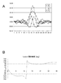
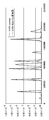
- FIG. 37 is a graph of an example of measurement of an error rate in the case where a disc with few defects is reproduced without performing an operation regarding a signal of an area.
- the disc reproducing apparatus shown in FIG. 1 is used.
- the disk used is a disk with a single-sided three-layer structure shown below.
- the solid line graph represents the error rate during groove reproduction, and the broken line graph represents the error rate during land reproduction.
- the horizontal axis is the number of clocks, and the vertical axis is the error rate.
- no particular problem occurs in the case of reproducing a disc with few defects.
- Signal recording density LD 35.18 GB (53 nm / channel bit) 50.0 GB / layer, equivalent to 300 GB with 6 layers on both sides Recording on both land and groove
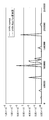
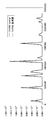
- FIG. 38 and FIG. 39 are graphs of measurement examples of error rates when a disc with many defects is reproduced.
- the vertical axis and the horizontal axis of the used disc and graph are the same as in FIG. FIG. 38 shows data at the time of groove reproduction, and FIG. 39 shows data at the time of land reproduction.
- the solid line graph indicates data in the case where no operation is performed on the signal of the region
- the broken line graph indicates data according to the present disclosure that performs the operation on the signal of the region as shown in Table 8. is there.
- the error rate can be reduced according to the present disclosure.
- the occurrence of an error can be suppressed by using an operation to calculate the difference between areas.
- the calculation coefficient may be changed according to the mark phase or the tendency of the defect.
- the coefficients can be optimized on the basis of the area ratio between the areas taking the difference and the light quantity ratio. In particular, such an effect is significant in the case of a division pattern (referred to as a T type) that uses outputs from a plurality of regions whose center positions are different in the tangential direction.
- the operation shown in Table 8 is a type of radial direction internal / external blend sum + difference type + tangential radial difference type. Further, an operation at the time of groove reproduction, an operation common to the groove and the land, and an operation at the time of land reproduction are shown.
- a Ch3 E-0.5 *
- a Ch4 F-0.5 *
- a Ch3 E-0.7 *
- a Ch4 F-0.7 *
- a Ch3 E-1.2 *
- a Ch4 F-1.2 * A
- each selection pattern is shown below. Here, it is configured to be different from the region on the outer side in the radial direction. For example, it is the radial direction internal / external blend sum difference type + tangential radial difference type.
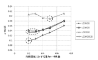
- Table 13 shows setting examples of the coefficients for the selection pattern IVR4M.
- FIG. 40 An example of the measurement of the error rate in the case of reproducing a disc with many defects by setting the coefficients as shown in Table 13 is shown in the graph of FIG.
- the vertical axis and the horizontal axis of the used disc and graph are the same as in FIG. FIG. 40 shows data at the time of groove reproduction.
- a solid line graph indicates data in the case where no operation is performed on the signal of the region
- a broken line graph is data according to the present disclosure that performs the operation on the signal of the region as shown in Table 13.
- the error rate can be reduced by the present disclosure.
- the occurrence of an error can be suppressed by using an operation to calculate the difference between areas.
- the calculation coefficient may be changed according to the mark phase or the tendency of the defect.
- the coefficients can be optimized on the basis of the area ratio between the areas taking the difference and the light quantity ratio.
- the signal characteristics are not significantly deteriorated even if the calculation between the regions is performed, taking the pattern VHT4 as an example.
- the signal names corresponding to the regions are changed as shown in FIG. As described below, even if the average signal level is multiplied by a gain (coefficient) approximately equal to twice, addition / subtraction does not significantly deteriorate the signal characteristics.
- the broken line corresponds to the average light intensity ratio between the regions Ta and Tb on the outer side in the tangential direction and the region R on the outer side in the radial direction.
- the range sandwiched by the broken lines corresponds to the average light amount ratio between the regions Ta and Tb on the outer side in the tangential direction and the region R on the outer side in the radial direction.
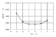
- Ch1 R + Krtct * (Ta + C + Tb)
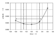
- the range sandwiched by the broken lines corresponds to the average light amount ratio between the outer regions Ta and Tb in the tangential direction and the central region C and the outer region R in the radial direction.
- the present disclosure it is possible to perform operations between regions and improve tolerance to disturbances such as defects.
- the signal characteristics are not significantly degraded even if the average light amount ratio (average signal level) is multiplied by a coefficient within a range from equivalent to about twice to be added / subtracted.
- the coefficients may be fixed or some constant may be prepared and switched. Furthermore, the coefficient may be variable. Furthermore, the inter-region operation may be performed using an analog circuit on OEIC (PDIC), or may be performed using a matrix circuit (analog circuit) separately provided with an OEIC output, or a digital signal using an A / D converter After converting into, it may carry out with a digital circuit.
- PDIC analog circuit on OEIC
- matrix circuit analog circuit
- the present disclosure it is possible to detect a defect by measuring the difference in characteristics by switching between the case of using the operation for improving the defect tolerance and the case of not using the operation, and the detection result for the defect countermeasure Can be used.
- it is useful to provide a mechanism to clean the disc such as by blowing air into the drive or library with dust on the disc surface, wiping or the like.
- the disk detection result may be used to control the operation of the cleaning mechanism.
- An optical medium reproducing apparatus for optically reproducing an optical medium in which a plurality of tracks are formed, comprising: An optical filter on which a return light beam from an optical medium is incident to form a plurality of signals having different bands in spatial and optical directions tangentially and radially; An operation unit that calculates a plurality of first signals formed by the optical filter to form a second signal of a plurality of channels; An optical medium reproducing apparatus comprising: an electric filter for receiving the second signal and processing the second signal to obtain a reproduction signal.
- the optical filter divides the light flux of the return light beam into a plurality of regions having different positions in the tangential direction and the radial direction, and a plurality of detection signals corresponding to the amounts of light respectively incident on the plurality of regions are The optical medium reproducing apparatus according to (1) or (2), wherein (4) The optical medium reproducing apparatus according to (3), wherein the arithmetic unit adds or subtracts the detection signals of a plurality of regions whose positions are different in the tangential direction to form the second signal. (5) The optical medium reproducing apparatus according to (3), wherein the operation unit adds or subtracts the detection signals of a plurality of regions which are located at different positions in the radial direction to form the second signal.
- the calculation unit adds or subtracts one of detection signals of a plurality of regions having different positions in the tangential direction and detection signals of a plurality of regions having different positions in the radial direction with respect to the other,
- the optical medium reproducing apparatus according to (3) which forms two signals.
- the electric filter includes a plurality of equalizer units to which signals of the plurality of channels are respectively supplied, and a multi-input equalizer unit that calculates outputs of the plurality of equalizer units and outputs as an equalization signal;
- the optical medium reproducing apparatus according to any one of (1) to (6), further comprising: a binarization unit that performs binarization processing on the equalized signal to obtain binary data.
- the multi-input equalizer unit is configured as a multi-input adaptive equalizer unit, An equalization error is obtained from the equalization target signal obtained based on the binary detection result of the binarization unit and the equalization signal output from the multi-input adaptive equalizer unit, and the equalization error is calculated by The optical medium reproducing apparatus according to (7), further comprising: an equalization error calculation unit which supplies an input adaptive equalizer unit as a control signal for adaptive equalization.
- the multi-input adaptive equalizer unit performs partial response equalization processing on an output signal
- the binarization unit performs maximum likelihood decoding processing as binarization processing on the equalization signal of the multi-input adaptive equalizer unit
- the equalization error calculation unit is an arithmetic operation using an equalization target signal obtained by convolution processing of binary detection results by the maximum likelihood decoding and an equalization signal output from the multi-input adaptive equalizer unit.
- the optical medium reproducing apparatus according to (8), which determines the conversion error.
- (10) In the optical medium lands and grooves are alternately formed, The optical medium reproducing apparatus according to any one of (1) to (9), which reproduces an optical medium having information recorded on both the land and the groove.
- An optical medium reproducing method for optically reproducing an optical medium in which a plurality of tracks are formed comprising: An optical filter forms a plurality of signals having different bands in spatial and optical directions tangentially and radially, with the return light beam from the incident optical medium, The arithmetic unit calculates a plurality of first signals formed by the optical filter to form second signals of a plurality of channels, A method of reproducing an optical medium, wherein an electrical filter processes the input second signal to obtain a reproduced signal.
- multi-input adaptive equalizer 14 binarization detector 15 PR convolution unit 21 to 23 adaptive equalizer unit 100 optical disk 101 optical pickup 105 data detection processing unit 131 optical filter 132 arithmetic unit 133 1 to 133 n electric filter
Landscapes
- Physics & Mathematics (AREA)
- Engineering & Computer Science (AREA)
- Signal Processing (AREA)
- Optics & Photonics (AREA)
- Mathematical Physics (AREA)
- Optical Recording Or Reproduction (AREA)
- Signal Processing For Digital Recording And Reproducing (AREA)
- Optical Head (AREA)
Priority Applications (2)
| Application Number | Priority Date | Filing Date | Title |
|---|---|---|---|
| US15/548,520 US9990952B2 (en) | 2015-02-12 | 2015-12-09 | Optical medium reproducing device and optical medium reproducing method |
| CN201580075463.7A CN107210049B (zh) | 2015-02-12 | 2015-12-09 | 光学介质再现装置和光学介质再现方法 |
Applications Claiming Priority (2)
| Application Number | Priority Date | Filing Date | Title |
|---|---|---|---|
| JP2015-025666 | 2015-02-12 | ||
| JP2015025666A JP6123821B2 (ja) | 2015-02-12 | 2015-02-12 | 光媒体再生装置及び光媒体再生方法 |
Publications (1)
| Publication Number | Publication Date |
|---|---|
| WO2016129022A1 true WO2016129022A1 (ja) | 2016-08-18 |
Family
ID=56614353
Family Applications (1)
| Application Number | Title | Priority Date | Filing Date |
|---|---|---|---|
| PCT/JP2015/006143 Ceased WO2016129022A1 (ja) | 2015-02-12 | 2015-12-09 | 光媒体再生装置及び光媒体再生方法 |
Country Status (4)
| Country | Link |
|---|---|
| US (1) | US9990952B2 (enExample) |
| JP (1) | JP6123821B2 (enExample) |
| CN (1) | CN107210049B (enExample) |
| WO (1) | WO2016129022A1 (enExample) |
Cited By (1)
| Publication number | Priority date | Publication date | Assignee | Title |
|---|---|---|---|---|
| EP3522161A4 (en) * | 2016-09-30 | 2019-10-16 | Sony Semiconductor Solutions Corporation | PLAYING DEVICE AND PLAYBACK PROCESS |
Families Citing this family (1)
| Publication number | Priority date | Publication date | Assignee | Title |
|---|---|---|---|---|
| WO2021159153A1 (en) | 2020-02-11 | 2021-08-19 | Innio Jenbacher Gmbh & Co Og | Internal combustion engine |
Citations (4)
| Publication number | Priority date | Publication date | Assignee | Title |
|---|---|---|---|---|
| JP2009199635A (ja) * | 2008-02-19 | 2009-09-03 | Sony Corp | 再生装置、再生方法、データ検出処理回路 |
| WO2014054246A1 (ja) * | 2012-10-05 | 2014-04-10 | パナソニック株式会社 | 情報再生装置及び情報再生方法 |
| WO2014203526A1 (ja) * | 2013-06-19 | 2014-12-24 | パナソニックIpマネジメント株式会社 | 光情報装置及び情報処理装置 |
| WO2014207972A1 (ja) * | 2013-06-28 | 2014-12-31 | ソニー株式会社 | 光媒体再生装置および光媒体再生方法 |
Family Cites Families (15)
| Publication number | Priority date | Publication date | Assignee | Title |
|---|---|---|---|---|
| JPS57111838A (en) * | 1980-12-27 | 1982-07-12 | Olympus Optical Co Ltd | Optical information reader |
| JP2723986B2 (ja) * | 1989-08-02 | 1998-03-09 | 株式会社日立製作所 | 光ディスク原盤の作製方法 |
| JPH05242512A (ja) | 1991-12-19 | 1993-09-21 | Matsushita Electric Ind Co Ltd | 光ディスク装置 |
| JPH07234382A (ja) * | 1994-02-24 | 1995-09-05 | Matsushita Electric Ind Co Ltd | 超解像走査光学装置 |
| JP3214537B2 (ja) | 1995-03-08 | 2001-10-02 | 日本電信電話株式会社 | 光ビームを用いたデータ再生方法及びその装置 |
| US5621717A (en) * | 1995-06-07 | 1997-04-15 | International Business Machines Corporation | Reading optical disks having substrates with diverse axial thicknesses |
| JP2000048488A (ja) * | 1998-07-27 | 2000-02-18 | Pioneer Electron Corp | クロストーク除去回路を有する記録情報再生装置 |
| JP4578656B2 (ja) * | 1999-09-16 | 2010-11-10 | 三星電子株式会社 | 光記録再生機器用エラー信号検出装置 |
| KR100636121B1 (ko) * | 2000-05-23 | 2006-10-18 | 삼성전자주식회사 | 광픽업장치 |
| US20060114791A1 (en) * | 2004-11-30 | 2006-06-01 | Charles Marshall | Ultra-high data density optical media system |
| CN101030409A (zh) * | 2006-03-03 | 2007-09-05 | 索尼株式会社 | 光拾取装置以及光盘装置 |
| JP5318033B2 (ja) * | 2010-05-28 | 2013-10-16 | 株式会社日立メディアエレクトロニクス | 光ピックアップ装置 |
| JP2012079385A (ja) | 2010-10-04 | 2012-04-19 | Sony Corp | データ検出装置、再生装置、データ検出方法 |
| JP6167918B2 (ja) * | 2013-08-14 | 2017-07-26 | ソニー株式会社 | 光媒体再生装置および光媒体再生方法 |
| WO2016006157A1 (ja) * | 2014-07-11 | 2016-01-14 | ソニー株式会社 | 光媒体再生装置および光媒体再生方法 |
-
2015
- 2015-02-12 JP JP2015025666A patent/JP6123821B2/ja not_active Expired - Fee Related
- 2015-12-09 US US15/548,520 patent/US9990952B2/en active Active
- 2015-12-09 WO PCT/JP2015/006143 patent/WO2016129022A1/ja not_active Ceased
- 2015-12-09 CN CN201580075463.7A patent/CN107210049B/zh not_active Expired - Fee Related
Patent Citations (4)
| Publication number | Priority date | Publication date | Assignee | Title |
|---|---|---|---|---|
| JP2009199635A (ja) * | 2008-02-19 | 2009-09-03 | Sony Corp | 再生装置、再生方法、データ検出処理回路 |
| WO2014054246A1 (ja) * | 2012-10-05 | 2014-04-10 | パナソニック株式会社 | 情報再生装置及び情報再生方法 |
| WO2014203526A1 (ja) * | 2013-06-19 | 2014-12-24 | パナソニックIpマネジメント株式会社 | 光情報装置及び情報処理装置 |
| WO2014207972A1 (ja) * | 2013-06-28 | 2014-12-31 | ソニー株式会社 | 光媒体再生装置および光媒体再生方法 |
Cited By (2)
| Publication number | Priority date | Publication date | Assignee | Title |
|---|---|---|---|---|
| EP3522161A4 (en) * | 2016-09-30 | 2019-10-16 | Sony Semiconductor Solutions Corporation | PLAYING DEVICE AND PLAYBACK PROCESS |
| US11335371B2 (en) | 2016-09-30 | 2022-05-17 | Sony Semiconductor Solutions Corporation | Reproduction apparatus and reproduction method |
Also Published As
| Publication number | Publication date |
|---|---|
| JP6123821B2 (ja) | 2017-05-10 |
| CN107210049B (zh) | 2020-09-01 |
| US9990952B2 (en) | 2018-06-05 |
| US20180096703A1 (en) | 2018-04-05 |
| JP2016149172A (ja) | 2016-08-18 |
| CN107210049A (zh) | 2017-09-26 |
Similar Documents
| Publication | Publication Date | Title |
|---|---|---|
| JP6167918B2 (ja) | 光媒体再生装置および光媒体再生方法 | |
| JP6489126B2 (ja) | 光媒体再生装置および光媒体再生方法 | |
| JP6311711B2 (ja) | 光媒体再生装置および光媒体再生方法 | |
| JP6428619B2 (ja) | 光媒体再生装置および光媒体再生方法 | |
| JP6123821B2 (ja) | 光媒体再生装置及び光媒体再生方法 | |
| JP6597779B2 (ja) | 光ディスク装置 | |
| JP6551418B2 (ja) | 光媒体再生装置及び光媒体再生方法 |
Legal Events
| Date | Code | Title | Description |
|---|---|---|---|
| 121 | Ep: the epo has been informed by wipo that ep was designated in this application |
Ref document number: 15881898 Country of ref document: EP Kind code of ref document: A1 |
|
| WWE | Wipo information: entry into national phase |
Ref document number: 15548520 Country of ref document: US |
|
| NENP | Non-entry into the national phase |
Ref country code: DE |
|
| 122 | Ep: pct application non-entry in european phase |
Ref document number: 15881898 Country of ref document: EP Kind code of ref document: A1 |