WO2016125675A1 - スイッチ - Google Patents
スイッチ Download PDFInfo
- Publication number
- WO2016125675A1 WO2016125675A1 PCT/JP2016/052466 JP2016052466W WO2016125675A1 WO 2016125675 A1 WO2016125675 A1 WO 2016125675A1 JP 2016052466 W JP2016052466 W JP 2016052466W WO 2016125675 A1 WO2016125675 A1 WO 2016125675A1
- Authority
- WO
- WIPO (PCT)
- Prior art keywords
- switch
- contact
- movable
- fixed
- arc
- Prior art date
- Legal status (The legal status is an assumption and is not a legal conclusion. Google has not performed a legal analysis and makes no representation as to the accuracy of the status listed.)
- Ceased
Links
Images




Classifications
-
- H—ELECTRICITY
- H01—ELECTRIC ELEMENTS
- H01H—ELECTRIC SWITCHES; RELAYS; SELECTORS; EMERGENCY PROTECTIVE DEVICES
- H01H33/00—High-tension or heavy-current switches with arc-extinguishing or arc-preventing means
- H01H33/02—Details
- H01H33/04—Means for extinguishing or preventing arc between current-carrying parts
- H01H33/18—Means for extinguishing or preventing arc between current-carrying parts using blow-out magnet
- H01H33/182—Means for extinguishing or preventing arc between current-carrying parts using blow-out magnet using permanent magnets
-
- H—ELECTRICITY
- H01—ELECTRIC ELEMENTS
- H01H—ELECTRIC SWITCHES; RELAYS; SELECTORS; EMERGENCY PROTECTIVE DEVICES
- H01H1/00—Contacts
- H01H1/12—Contacts characterised by the manner in which co-operating contacts engage
- H01H1/14—Contacts characterised by the manner in which co-operating contacts engage by abutting
- H01H1/24—Contacts characterised by the manner in which co-operating contacts engage by abutting with resilient mounting
- H01H1/26—Contacts characterised by the manner in which co-operating contacts engage by abutting with resilient mounting with spring blade support
-
- H—ELECTRICITY
- H01—ELECTRIC ELEMENTS
- H01H—ELECTRIC SWITCHES; RELAYS; SELECTORS; EMERGENCY PROTECTIVE DEVICES
- H01H9/00—Details of switching devices, not covered by groups H01H1/00 - H01H7/00
- H01H9/30—Means for extinguishing or preventing arc between current-carrying parts
- H01H9/44—Means for extinguishing or preventing arc between current-carrying parts using blow-out magnet
- H01H9/443—Means for extinguishing or preventing arc between current-carrying parts using blow-out magnet using permanent magnets
-
- H—ELECTRICITY
- H01—ELECTRIC ELEMENTS
- H01H—ELECTRIC SWITCHES; RELAYS; SELECTORS; EMERGENCY PROTECTIVE DEVICES
- H01H9/00—Details of switching devices, not covered by groups H01H1/00 - H01H7/00
- H01H9/30—Means for extinguishing or preventing arc between current-carrying parts
- H01H9/40—Multiple main contacts for the purpose of dividing the current through, or potential drop along, the arc
Definitions
- the present invention relates to a switch.
- Patent Document 1 is a structure using a permanent magnet to extinguish the generated arc, and one permanent magnet is installed for each set of contacts consisting of a fixed contact and a movable contact.
- a switch having a plurality of contact sets for example, a switch having two contact points called a double switch is used.
- the number of permanent magnets corresponding to the set of contacts i.e., two pieces, is required.
- a bad effect such as a heavy switch occurs.
- a first switch having a first fixed contact and a first movable contact
- a second switch having a second fixed contact and a second movable contact
- a switch that is turned on when the first fixed contact and the first movable contact are in contact with each other and the second fixed contact and the second movable contact are in contact with each other.
- a magnet is installed between the switch and the second switch.
- an arc can be extinguished at a low cost without increasing the size in a switch having a plurality of contact sets.
- the switch described in the present embodiment corresponds to a high voltage.
- the high voltage means “over 750 VDC” defined in electrical equipment technical standards, It does not mean “DC 1500V or higher”, which is an international regulation by the International Electrotechnical Commission (IEC), but means a voltage exceeding a safe low voltage (less than DC 60V), that is, 60V or higher. .
- FIGS. 1 is a front view of the main part of the switch according to the present embodiment
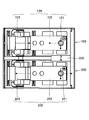
- FIG. 2 is a top view
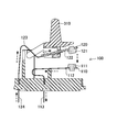
- FIG. 3 is a cross-sectional view of the first switch 100
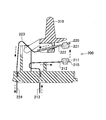
- FIG. 4 is the second switch.
- FIG. The switch in the present embodiment is called a double cut switch, and has a first switch 100 and a second switch 200 as shown in FIGS.
- the first switch 100 has a first fixed part 110 and a first movable part 120
- the second switch 200 has a second fixed part 210 and a second movable part 220. is doing.
- the first fixed portion 110 and the first movable portion 120 are in contact with each other, and the second fixed portion 210 and the second movable portion 220 are in contact with each other to turn on. Power is supplied to the devices. Note that in a state where either the first switch 100 or the second switch 200 is not in contact, the switch is turned off, and power is not supplied to the electronic device or the like.
- the first fixed portion 110 has a first fixed contact 111 and a first fixed spring 112, and a first fixed portion external terminal 113 is connected to the first fixed spring 112.
- the second fixed portion 210 has a second fixed contact 211 and a second fixed spring 212, and a second fixed portion external terminal 213 is connected to the second fixed spring 212.
- the first movable portion 120 includes a first movable contact 121, a first movable plate 122, and a first movable spring 123, and the first movable portion 123 includes a first movable portion external terminal 124. Is connected.
- the second movable portion 220 includes a second movable contact 221, a second movable plate 222, and a second movable spring 223, and a second movable portion external terminal 224 is connected thereto.
- Both the first movable plate 122 and the second movable plate 222 are connected to the card 310. Therefore, by pushing down the card 310, the one movable contact 121 and the second movable contact 221 can be moved downward. Accordingly, the first movable contact 121 can be brought into contact with the first fixed contact 111, and the second movable contact 221 can be brought into contact with the second fixed contact 211. In this way, the switch in the present embodiment is turned on.
- a permanent magnet 320 that extinguishes the arc is installed between the first switch 100 and the second switch 200. More specifically, the permanent magnet 320 includes a portion where the first fixed contact 111 and the first movable contact 121 are disposed, and a second fixed contact 211 and the second movable contact 221 which are disposed. It is installed in between. Thereby, a magnetic field can be generated in the region between the contacts of the first switch 100 and the region between the contacts of the second switch 200. Thus, by generating a magnetic field in the region between the contacts, when an arc is generated between the contacts, the arc can be skipped and the arc can be extinguished efficiently.
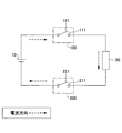
- the switch in the present embodiment is connected to a DC power supply 10 and an electronic device 20 as a load, as shown in FIG.
- the positive electrode of the DC power supply 10 is connected to the first movable contact 121, and the first fixed contact 111 is connected to the electronic device 20.
- the negative electrode of the DC power supply 10 is connected to the second movable contact 221, and the second fixed contact 211 is connected to the electronic device 20.
- the switch according to the present embodiment when the switch according to the present embodiment is connected to the DC power supply 10 and the electronic device 20, when the switch is turned on, the current is indicated by the broken line arrows in FIGS. It flows in the direction. Specifically, in the first switch 100, current flows from the first movable contact 121 toward the first fixed contact 111, and in the second switch 200, current flows from the second fixed contact 211 to the second movable contact. It flows toward the contact 221. As shown in FIG. 2, when the permanent magnet 320 is installed so that the first switch 100 side becomes the S pole and the second switch 200 side becomes the N pole, the magnetic field of the permanent magnet 320 in FIG. It occurs in the direction indicated by the dashed-dotted arrow.
- the arc is directed in the direction indicated by the two-dot chain line arrow, that is, in the direction in which the first movable spring 123 and the first fixed spring 112 are provided in the first switch 100 when viewed from the contact point.
- the second switch 200 can fly in the direction opposite to the direction in which the second movable spring 223 and the second fixed spring 212 are provided when viewed from the contact point.
- the arc generated between the respective contacts can be blown by the single permanent magnet 320. Therefore, it is possible to obtain a switch that is small, lightweight, low cost, and capable of extinguishing the arc.
- the permanent magnet 320 is replaced with a first fixed contact 111, a first movable contact 121, a second fixed contact 211, a second movable contact 221. It may be installed at a position shifted from the middle position to the outside (right side in FIG. 6). In this case, the direction of the magnetic field acting at each contact position is oblique with respect to the extending direction of the movable spring / fixed spring as shown by the two-dot chain arrows in FIG.
- the arc generated in the first switch 100 can be blown in a direction that is not parallel to the direction of current flow in the first fixed spring 112 and the first movable spring 123, and the arc can be easily extinguished.
- the arc generated by the second switch 200 can also be blown in a direction that is not parallel to the direction along the second fixed spring 212 and the second movable spring 223.
- the direction of current flow is indicated by a broken line arrow
- the direction of the magnetic field generated by the permanent magnet 320 is indicated by a one-dot chain line arrow
- the direction of the arc is indicated by a two-dot chain line arrow.
- the switch in this embodiment can be used as a single switch, or can be used as a connector with a switch in which the switch is incorporated.
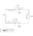
- FIGS. 7 is a circuit diagram showing the connection state of the switch in the present embodiment
- FIG. 8 is a top view of the main part of the switch in the present embodiment
- FIG. FIG. 10 is a sectional view of the second switch 200.
- the switch in the present embodiment is connected to the DC power supply 10 and the electronic device 20 as shown in FIG.
- the positive electrode of the DC power supply 10 is connected to the first movable contact 121, and the first fixed contact 111 is connected to the positive electrode terminal of the electronic device 20.
- the negative electrode of the DC power supply 10 is connected to the second fixed contact 211, and the second movable contact 221 is connected to the negative terminal of the electronic device 20.
- the current is shown by the broken line in FIG. 8, FIG. 9, and FIG. It flows in the direction indicated by the arrow. Specifically, the current flows from the first movable contact 121 to the first fixed contact 111 in the first switch 100, and also from the second movable contact 221 to the second switch 200 in the second switch 200. It flows toward the fixed contact 211.
- the permanent magnet 320 is installed so that the first switch 100 side becomes the S pole and the second switch 200 side becomes the N pole, the magnetic field generated by the permanent magnet 320 is 8 occurs in the direction indicated by the dashed-dotted arrow.
- the arc generated between the contacts of the first switch 100 is the direction indicated by the two-dot chain line arrow, that is, the direction in which the first movable spring 123 and the first fixed spring 112 are provided as viewed from the contact. You can fly in the opposite direction.
- the second movable spring 223 and the second fixed spring 212 can be blown in the direction opposite to the direction in which the second movable spring 223 and the second fixed spring 212 are provided.
- the first switch 100 can blow an arc away from the first fixed portion 110 and the first movable portion 120
- the second switch 200 can also discharge the second fixed portion 210 and the second fixed portion 210.
- the arc can be blown away from the movable part 220.
- the current flows from the first movable contact 121 to the first fixed contact 111 in the first switch 100, and the second fixed contact from the second movable contact 221 also in the second switch 200.
- the switch is connected to the power source and the load so that current flows from the fixed contact to the movable contact, and the permanent magnet 320 is reversed, that is, the first switch
- the switch 100 side may be an N pole
- the second switch 200 side may be an S pole.
- the switch according to the present embodiment has a structure in which a yoke 330 for concentrating a magnetic field is provided in a region between a fixed contact and a movable contact. That is, the magnetic field generated by the permanent magnet 320 is generated between the first fixed contact 111 and the first movable contact 121, and between the second fixed contact 211 and the second movable contact 221.
- a yoke 330 is provided for concentrating on the area between the contacts.
- the yoke 330 is formed in a U shape.
- a permanent magnet 320 is installed in the vicinity of the center inside the yoke 330.
- the first fixed contact 111, the first movable contact 121, the second fixed contact 211, and the second movable contact 221 are installed so as to be located inside the U-shaped portion of the yoke 330. Therefore, the first fixed contact 111 and the first movable contact 121 are sandwiched between the one end 331 of the yoke 330 and the permanent magnet 320, and the second fixed contact 211 and the second movable contact 221. Is sandwiched between the other end 332 of the yoke 330 and the permanent magnet 320.
- the yoke 330 is formed of a material containing a magnetic material such as iron, cobalt, nickel. Further, the permanent magnet 320 and the yoke 330 are in contact with each other so as to reduce the leakage of magnetic flux, and the magnetic flux generated in the permanent magnet 320 passes through the yoke 330. That is, the magnetic flux from the permanent magnet 320 passes through the yoke 330 as shown by a one-dot chain line in FIG. 11, between the first fixed contact 111 and the first movable contact 121, and between the second fixed contact 211 and the first fixed contact. It passes between the two movable contacts 221.
- the region between the contacts of the first switch 100 and the region between the contacts of the second switch 200 that are sandwiched between one end 331 of the yoke 330 and the permanent magnet 320 are permanent.
- the magnetic field generated by the magnet 320 can be concentrated.
- the magnetic field in the region between the first fixed contact 111 and the first movable contact 121 and the region between the second fixed contact 211 and the second movable contact 221 can be increased. Even if an arc occurs between them, the arc can be extinguished efficiently and in a short time.
- the contents other than the above are the same as in the first embodiment.
Landscapes
- Arc-Extinguishing Devices That Are Switches (AREA)
Abstract
第1の固定接点(111)と第1の可動接点(121)とを有する第1のスイッチ(100)と、第2の固定接点(211)と第2の可動接点(221)とを有する第2のスイッチ(200)と、を有するスイッチ。前記第1の固定接点(111)と前記第1の可動接点(121)とが接触し、前記第2の固定接点(211)と前記第2の可動接点(221)とが接触することによりオンとなる。前記第1のスイッチ(100)と、前記第2のスイッチ(200)との間に、磁石(320)が設置されている。
Description
本発明は、スイッチに関する。
電気機器が、電源から電力の供給を受ける際には、電源と電気機器とがコネクタにより接続され、この状態で、スイッチのオンオフ制御を行うことにより、電力の供給がなされる。
近年、地球温暖化等に対する対策の一つとして、ローカルエリアにおける送電においても、直流で高電圧の電力の供給が検討されている。直流で高電圧の電力の供給は、電圧変換や送電等における電力損失が少なく、ケーブルの太さも太くする必要がない。特に、サーバ等の情報機器においては、大量に電力を消費するため、このような電力供給が望ましいものとされている。
ところで、このような高電圧の電力の供給の制御をスイッチにより行う場合、スイッチにおける端子間にアークが発生する場合がある。このようなアークが発生すると、アークによる熱により各々の端子が破壊される場合があるため、発生したアークを短時間で消弧する方法が検討されている。
特許文献1において開示されている方法は、発生したアークを消弧するため永久磁石を用いた構造のものであり、固定接点と可動接点からなる一組の接点ごとに、一つの永久磁石が設置されている。しかしながら、高電圧の電力の供給を制御する場合には、複数の接点の組を有するスイッチ、例えば、両切りスイッチと呼ばれる二組の接点を有するスイッチが用いられる。このような両切りスイッチ等において、一組の接点ごとに一つの永久磁石を設置すると、永久磁石は接点の組に対応した数、即ち、二個必要となるため、スイッチのコストアップ、大型化、更には、スイッチが重くなるといった弊害が生じてしまう。
このため、複数の接点の組を有しているスイッチにおいて、大型化することなく低コストで、アークを消弧することのできるスイッチが求められている。
本発明の一側面によれば、第1の固定接点と第1の可動接点とを有する第1のスイッチと、第2の固定接点と第2の可動接点とを有する第2のスイッチと、を有し、前記第1の固定接点と前記第1の可動接点とが接触し、前記第2の固定接点と前記第2の可動接点とが接触することによりオンとなるスイッチにおいて、前記第1のスイッチと、前記第2のスイッチとの間に、磁石が設置されていることを特徴とする。
本発明の一実施例によれば、複数の接点の組を有しているスイッチにおいて、大型化することなく低コストで、アークを消弧することができる。
本発明を実施するための形態について、以下に説明する。尚、同じ部材等については、同一の符号を付して説明を省略する。
本実施の形態において説明するスイッチは、高電圧に対応しているものであるが、本実施の形態においては、高電圧とは、電気設備技術基準に定められている「直流750V超」や、国際電気標準会議(IEC:International Electrotechnical Commission)による国際規定である「直流1500V以上」を意味するものではなく、安全低電圧(直流60V未満)を超える電圧、即ち、60V以上を意味するものとする。
本実施の形態において説明するスイッチは、高電圧に対応しているものであるが、本実施の形態においては、高電圧とは、電気設備技術基準に定められている「直流750V超」や、国際電気標準会議(IEC:International Electrotechnical Commission)による国際規定である「直流1500V以上」を意味するものではなく、安全低電圧(直流60V未満)を超える電圧、即ち、60V以上を意味するものとする。
〔第1の実施の形態〕
第1の実施の形態におけるスイッチについて、図1から図5に基づき説明する。尚、図1は、本実施の形態におけるスイッチの要部における正面図であり、図2は上面図であり、図3は第1のスイッチ100における断面図であり、図4は第2のスイッチ200における断面図である。
本実施の形態におけるスイッチは、両切りスイッチと呼ばれるものであり、図1から図4に示されるように、第1のスイッチ100と第2のスイッチ200とを有している。第1のスイッチ100は、第1の固定部110と第1の可動部120とを有しており、第2のスイッチ200は、第2の固定部210と第2の可動部220とを有している。
本実施の形態におけるスイッチでは、第1の固定部110と第1の可動部120とが接触し、第2の固定部210と第2の可動部220とが接触することによりオンとなり、電子機器等への電力の供給がなされる。尚、第1のスイッチ100、または、第2のスイッチ200のうちのいずれか一方が接触していない状態においてはスイッチはオフ状態となり、電子機器等への電力の供給はなされない。
第1の実施の形態におけるスイッチについて、図1から図5に基づき説明する。尚、図1は、本実施の形態におけるスイッチの要部における正面図であり、図2は上面図であり、図3は第1のスイッチ100における断面図であり、図4は第2のスイッチ200における断面図である。
本実施の形態におけるスイッチは、両切りスイッチと呼ばれるものであり、図1から図4に示されるように、第1のスイッチ100と第2のスイッチ200とを有している。第1のスイッチ100は、第1の固定部110と第1の可動部120とを有しており、第2のスイッチ200は、第2の固定部210と第2の可動部220とを有している。
本実施の形態におけるスイッチでは、第1の固定部110と第1の可動部120とが接触し、第2の固定部210と第2の可動部220とが接触することによりオンとなり、電子機器等への電力の供給がなされる。尚、第1のスイッチ100、または、第2のスイッチ200のうちのいずれか一方が接触していない状態においてはスイッチはオフ状態となり、電子機器等への電力の供給はなされない。
第1の固定部110は、第1の固定接点111及び第1の固定バネ112を有しており、第1の固定バネ112には第1の固定部外部端子113が接続されている。第2の固定部210は、第2の固定接点211及び第2の固定バネ212を有しており、第2の固定バネ212には第2の固定部外部端子213が接続されている。第1の可動部120は、第1の可動接点121、第1の可動板122及び第1の可動バネ123を有しており、第1の可動バネ123には第1の可動部外部端子124が接続されている。第2の可動部220は、第2の可動接点221、第2の可動板222及び第2の可動バネ223を有しており、第2の可動部外部端子224が接続されている。
第1の可動板122及びの第2の可動板222は、ともにカード310に接続されている。よって、カード310を押し下げることにより、1の可動接点121及び第2の可動接点221を下方向に動かすことができる。これにより、第1の可動接点121を第1の固定接点111に接触させるとともに、第2の可動接点221を第2の固定接点211に接触させることができる。このようにして、本実施の形態におけるスイッチはオンとなる。
本実施の形態におけるスイッチでは、アークを消弧する永久磁石320が第1のスイッチ100と第2のスイッチ200との間に設置されている。より詳細には、永久磁石320は、第1の固定接点111及び第1の可動接点と121とが配置される部分と、第2の固定接点211及び第2の可動接点と221とが配置される部分との間に設置されている。これにより、第1のスイッチ100の接点間領域、及び第2のスイッチ200の接点間領域に、磁界を発生させることができる。このように、接点間領域に磁界を発生させることにより、接点間にアークが発生した場合にアークを飛ばし、効率よくアークを消弧することができる。
本実施の形態におけるスイッチは、図5に示されるように、直流電源10及び負荷となる電子機器20に接続される。直流電源10の正極は第1の可動接点121と接続されており、第1の固定接点111は電子機器20に接続されている。また、直流電源10の負極は第2の可動接点221と接続されており、第2の固定接点211は電子機器20に接続されている。
図5に示されるように本実施の形態におけるスイッチを直流電源10及び電子機器20に接続することにより、スイッチがオンとなった場合には、電流は図2、図3、図4における破線矢印の向きに流れる。具体的には、第1のスイッチ100において電流は第1の可動接点121から第1の固定接点111に向かって流れ、第2のスイッチ200において電流は第2の固定接点211から第2の可動接点221に向かって流れる。図2に示されるように、第1のスイッチ100側がS極となり、第2のスイッチ200側がN極となるように永久磁石320が設置されている場合、永久磁石320の磁界は、図2において一点鎖線の矢印で示される方向に発生する。よって、アークは、二点鎖線の矢印で示される方向、即ち、第1のスイッチ100においては接点から見て第1の可動バネ123及び第1の固定バネ112が設けられている方向に向かって飛ばすことができ、第2のスイッチ200においては、接点から見て第2の可動バネ223及び第2の固定バネ212が設けられている方向とは反対方向に向かって飛ばすことができる。
本実施の形態においては、第1のスイッチ100及び第2のスイッチ200を有する両切りスイッチにおいても、一つの永久磁石320により、各々の接点間において発生したアークを飛ばすことができる。従って、小型で、軽量で、低コストで、アークを消弧することのできるスイッチを得ることができる。
尚、本実施の形態におけるスイッチでは、図6に示すように、永久磁石320を第1の固定接点111・第1の可動接点と121と第2の固定接点211・第2の可動接点と221との中間の位置より外側(図6図示右側)にずれた位置に設置してもよい。この場合、各接点位置に働く磁界の向きは、図6図示二点鎖線の矢印で示すように可動バネ・固定バネの延長方向に対して斜め向きとなる。これにより、第1のスイッチ100で発生するアークを、第1の固定バネ112及び第1の可動バネ123において電流の流れる方向とは平行ではない方向に飛ばすことができ、アークを消弧しやすい。第2のスイッチ200で発生するアークについても、第2の固定バネ212及び第2の可動バネ223に沿った方向とは平行ではない方向に飛ばすことができる。尚、図6においては、電流の流れる方向を破線矢印で示し、永久磁石320により生じた磁界の方向を一点鎖線矢印で示し、アークの飛ぶ方向を二点鎖線矢印により示す。
図2の場合には、第1のスイッチ100で発生したアークは第1の可動バネ123の根元に向けて飛ばされるため、第1の可動バネ123の根元ではそれ以上アークを伸ばすことができず、アークの消弧が十分にできない可能性がある。一方、図6のようにアークを飛ばすことで、接点間に発生したアークを十分伸ばすことができ、より効果的にアークを消弧することが可能となる。
本実施の形態におけるスイッチはスイッチ単体として用いることができ、また、コネクタにスイッチを組み入れたスイッチ付きコネクタとして用いることも可能である。
〔第2の実施の形態〕
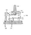
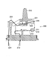
次に、第2の実施の形態について説明する。本実施の形態におけるスイッチは、第1のスイッチ100及び第2のスイッチ200の双方において、電流が可動接点から固定接点に流れるようにしている。本実施の形態におけるスイッチについて、図7から図10に基づき説明する。尚、図7は、本実施の形態におけるスイッチの接続状態を示す回路図であり、図8は、本実施の形態におけるスイッチの要部の上面図であり、図9は第1のスイッチ100における断面図であり、図10は第2のスイッチ200における断面図である。
次に、第2の実施の形態について説明する。本実施の形態におけるスイッチは、第1のスイッチ100及び第2のスイッチ200の双方において、電流が可動接点から固定接点に流れるようにしている。本実施の形態におけるスイッチについて、図7から図10に基づき説明する。尚、図7は、本実施の形態におけるスイッチの接続状態を示す回路図であり、図8は、本実施の形態におけるスイッチの要部の上面図であり、図9は第1のスイッチ100における断面図であり、図10は第2のスイッチ200における断面図である。
本実施の形態におけるスイッチは、図7に示されるように直流電源10及び電子機器20に接続される。直流電源10の正極は第1の可動接点121と接続されており、第1の固定接点111は電子機器20の正極端子に接続されている。また、直流電源10の負極は、第2の固定接点211と接続されており、第2の可動接点221は電子機器20の負極端子に接続されている。
本実施の形態におけるスイッチを図7に示されるように直流電源10及び電子機器20に接続することにより、スイッチがオンとなった際には、電流は、図8、図9、図10における破線矢印に示される向きに流れる。具体的には、電流は、第1のスイッチ100においては第1の可動接点121から第1の固定接点111に向かって流れ、第2のスイッチ200においても第2の可動接点221から第2の固定接点211に向かって流れる。図8に示されるように、第1のスイッチ100側がS極となり、第2のスイッチ200側がN極となるように永久磁石320が設置されている場合、永久磁石320が発生する磁界は、図8において一点鎖線の矢印で示される方向に発生する。
よって、第1のスイッチ100の接点間に発生するアークは、二点鎖線の矢印で示される方向、即ち接点から見て第1の可動バネ123及び第1の固定バネ112が設けられている方向とは反対方向に飛ばすことができる。また、第2のスイッチ200においても、接点から見て第2の可動バネ223及び第2の固定バネ212が設けられている方向とは反対方向に飛ばすことができる。言い換えるならば、第1のスイッチ100では第1の固定部110及び第1の可動部120から離れる方向にアークを飛ばすことができ、第2のスイッチ200でも第2の固定部210及び第2の可動部220から離れる方向にアークを飛ばすことができる。
尚、上記においては、電流が、第1のスイッチ100では第1の可動接点121から第1の固定接点111に向かって流れ、第2のスイッチ200でも第2の可動接点221から第2の固定接点211に向かって流れる場合について説明した。しかしながら、第1のスイッチ100及び第2のスイッチ200の双方において固定接点から可動接点に向かうように電流が流れるようにスイッチを電源および負荷に接続し、永久磁石320を逆向き、即ち、第1のスイッチ100側がN極となり、第2のスイッチ200側がS極となるように設置してもよい。
尚、上記以外の構成は第1の実施の形態と同様である。
〔第3の実施の形態〕
次に、第3の実施の形態について、図11及び図12に基づき説明する。本実施の形態によるスイッチは、固定接点と可動接点との間の領域に磁界を集中させるためのヨーク330が設けられている構造のものである。即ち、永久磁石320により発生した磁界を第1の固定接点111と第1の可動接点121との間の接点間の領域、および第2の固定接点211と第2の可動接点221との間の接点間の領域に集中させるためのヨーク330が設けられている。
〔第3の実施の形態〕
次に、第3の実施の形態について、図11及び図12に基づき説明する。本実施の形態によるスイッチは、固定接点と可動接点との間の領域に磁界を集中させるためのヨーク330が設けられている構造のものである。即ち、永久磁石320により発生した磁界を第1の固定接点111と第1の可動接点121との間の接点間の領域、および第2の固定接点211と第2の可動接点221との間の接点間の領域に集中させるためのヨーク330が設けられている。
ヨーク330はコの字状に形成されている。ヨーク330の内側の中央近傍には永久磁石320が設置されている。第1の固定接点111及び第1の可動接点121、第2の固定接点211及び第2の可動接点221は、ヨーク330のコの字状部分の内側に位置するように設置されている。よって、第1の固定接点111及び第1の可動接点121はヨーク330の一方の端部331と永久磁石320との間に挟まれており、第2の固定接点211及び第2の可動接点221はヨーク330の他方の端部332と永久磁石320との間に挟まれている。
ヨーク330は、鉄、コバルト、ニッケル等の磁性材料を含む材料により形成されている。また、永久磁石320とヨーク330は磁束の漏れが少なくなるように接しており、永久磁石320において発生した磁束は、ヨーク330内を通る。即ち、永久磁石320からの磁束は図11に一点鎖線で示されるようにヨーク330内を通り、第1の固定接点111と第1の可動接点121との間、第2の固定接点211と第2の可動接点221との間を通る。
本実施の形態においては、ヨーク330の一方の端部331と永久磁石320との間に挟まれている第1のスイッチ100の接点間の領域および第2のスイッチ200の接点間の領域に永久磁石320により発生した磁界を集中させることができる。これにより、第1の固定接点111と第1の可動接点121との間の領域、および第2の固定接点211と第2の可動接点221との間の領域における磁界を強めることができ、接点間にアークが発生してもアークを効率よく短時間で消弧することができる。
尚、上記以外の内容については、第1の実施の形態と同様である。
尚、上記以外の内容については、第1の実施の形態と同様である。
以上、本発明の実施に係る形態について説明したが、上記内容は、発明の内容を限定するものではない。
本国際出願は、2015年2月6日に出願された日本国特許出願2015-022620号に基づく優先権を主張するものであり、2015-022620号の全内容をここに本国際出願に援用する。
10 電源
20 電子機器
100 第1のスイッチ
110 第1の固定部
111 第1の固定接点
112 第1の固定バネ
113 第1の固定部外部端子
120 第1の可動部
121 第1の可動接点
122 第1の可動板
123 第1の可動バネ
124 第1の可動部外部端子
200 第2のスイッチ
210 第2の固定部
211 第2の固定接点
212 第2の固定バネ
213 第2の固定部外部端子
220 第2の可動部
221 第2の可動接点
222 第2の可動板
223 第2の可動バネ
224 第2の可動部外部端子
310 カード
320 永久磁石
330 ヨーク
331 一方の端部
332 他方の端部
20 電子機器
100 第1のスイッチ
110 第1の固定部
111 第1の固定接点
112 第1の固定バネ
113 第1の固定部外部端子
120 第1の可動部
121 第1の可動接点
122 第1の可動板
123 第1の可動バネ
124 第1の可動部外部端子
200 第2のスイッチ
210 第2の固定部
211 第2の固定接点
212 第2の固定バネ
213 第2の固定部外部端子
220 第2の可動部
221 第2の可動接点
222 第2の可動板
223 第2の可動バネ
224 第2の可動部外部端子
310 カード
320 永久磁石
330 ヨーク
331 一方の端部
332 他方の端部
Claims (3)
- 第1の固定接点と第1の可動接点とを有する第1のスイッチと、
第2の固定接点と第2の可動接点とを有する第2のスイッチと、
を有し、前記第1の固定接点と前記第1の可動接点とが接触し、前記第2の固定接点と前記第2の可動接点とが接触することによりオンとなるスイッチにおいて、
前記第1のスイッチと、前記第2のスイッチとの間に、磁石が設置されていることを特徴とするスイッチ。 - コの字状に形成されたヨークを有しており、
前記ヨークと前記磁石とは接しており、
前記ヨークの一方の端部と前記磁石との間には、前記第1のスイッチが位置しており、
前記ヨークの他方の端部と前記磁石との間には、前記第2のスイッチが位置していることを特徴とする請求項1に記載のスイッチ。 - 前記スイッチは、両切りスイッチであることを特徴とする請求項1に記載のスイッチ。
Priority Applications (2)
| Application Number | Priority Date | Filing Date | Title |
|---|---|---|---|
| CN201680007196.4A CN107210152B (zh) | 2015-02-06 | 2016-01-28 | 开关 |
| US15/543,644 US10262818B2 (en) | 2015-02-06 | 2016-01-28 | Switch |
Applications Claiming Priority (2)
| Application Number | Priority Date | Filing Date | Title |
|---|---|---|---|
| JP2015022620A JP6548905B2 (ja) | 2015-02-06 | 2015-02-06 | スイッチ |
| JP2015-022620 | 2015-02-06 |
Publications (1)
| Publication Number | Publication Date |
|---|---|
| WO2016125675A1 true WO2016125675A1 (ja) | 2016-08-11 |
Family
ID=56564023
Family Applications (1)
| Application Number | Title | Priority Date | Filing Date |
|---|---|---|---|
| PCT/JP2016/052466 Ceased WO2016125675A1 (ja) | 2015-02-06 | 2016-01-28 | スイッチ |
Country Status (4)
| Country | Link |
|---|---|
| US (1) | US10262818B2 (ja) |
| JP (1) | JP6548905B2 (ja) |
| CN (2) | CN110676079A (ja) |
| WO (1) | WO2016125675A1 (ja) |
Citations (4)
| Publication number | Priority date | Publication date | Assignee | Title |
|---|---|---|---|---|
| JPH10154448A (ja) * | 1996-11-25 | 1998-06-09 | Matsushita Electric Works Ltd | 直流開閉器 |
| JP2004355844A (ja) * | 2003-05-27 | 2004-12-16 | Mitsuba Corp | 電磁継電器 |
| JP2010073352A (ja) * | 2008-09-16 | 2010-04-02 | Denso Corp | 電磁継電器 |
| JP2013041690A (ja) * | 2011-08-11 | 2013-02-28 | Fujitsu Component Ltd | スイッチ及びコネクタ |
Family Cites Families (16)
| Publication number | Priority date | Publication date | Assignee | Title |
|---|---|---|---|---|
| US4810841A (en) * | 1986-07-31 | 1989-03-07 | Siemens Aktiengesellschaft | Current-limiting switching element |
| CN201289820Y (zh) * | 2008-10-24 | 2009-08-12 | 邢东波 | 触点全封闭永磁开关 |
| JP5284882B2 (ja) * | 2009-06-12 | 2013-09-11 | アンデン株式会社 | 電磁継電器 |
| EP2463878A1 (de) * | 2010-12-07 | 2012-06-13 | Eaton Industries GmbH | Schalter mit Löschkammer |
| EP2463876A1 (de) * | 2010-12-07 | 2012-06-13 | Eaton Industries GmbH | Schalter mit Löschkammer |
| JP5806562B2 (ja) * | 2011-01-12 | 2015-11-10 | 富士電機株式会社 | 電磁接触器 |
| JP5727862B2 (ja) * | 2011-05-19 | 2015-06-03 | 富士電機機器制御株式会社 | 電磁接触器 |
| EP2600367A1 (de) * | 2011-11-29 | 2013-06-05 | Eaton Industries GmbH | Schaltgerät für Gleichstromanwendungen |
| JP5852918B2 (ja) * | 2012-02-09 | 2016-02-03 | 株式会社日本自動車部品総合研究所 | ソレノイド装置及び電磁継電器 |
| JP5738209B2 (ja) * | 2012-02-09 | 2015-06-17 | 株式会社日本自動車部品総合研究所 | 電磁継電器 |
| JP5990028B2 (ja) * | 2012-04-13 | 2016-09-07 | 富士電機機器制御株式会社 | 接点装置及びこれを使用した電磁開閉器 |
| JP5965197B2 (ja) * | 2012-04-13 | 2016-08-03 | 富士電機機器制御株式会社 | 開閉器 |
| US9129761B2 (en) * | 2012-12-20 | 2015-09-08 | Eaton Electrical Ip Gmbh & Co. Kg | Switching device suitable for direct current operation |
| US20150130566A1 (en) * | 2013-11-14 | 2015-05-14 | James K. Kinsella | Means for providing improved operation properties for electrically operated circuit breakers, disconnect switches, and contactors |
| DE102014002902B4 (de) * | 2014-02-27 | 2019-08-01 | Schaltbau Gmbh | Löschkammer für ein Schütz und ein Schütz zum Löschen von Lichtbögen |
| US9349555B2 (en) * | 2014-07-09 | 2016-05-24 | Siemens Industry, Inc. | Current limited electrical devices, electrical device contact assemblies, and operational methods |
-
2015
- 2015-02-06 JP JP2015022620A patent/JP6548905B2/ja not_active Expired - Fee Related
-
2016
- 2016-01-28 CN CN201910956076.4A patent/CN110676079A/zh active Pending
- 2016-01-28 CN CN201680007196.4A patent/CN107210152B/zh not_active Expired - Fee Related
- 2016-01-28 US US15/543,644 patent/US10262818B2/en not_active Expired - Fee Related
- 2016-01-28 WO PCT/JP2016/052466 patent/WO2016125675A1/ja not_active Ceased
Patent Citations (4)
| Publication number | Priority date | Publication date | Assignee | Title |
|---|---|---|---|---|
| JPH10154448A (ja) * | 1996-11-25 | 1998-06-09 | Matsushita Electric Works Ltd | 直流開閉器 |
| JP2004355844A (ja) * | 2003-05-27 | 2004-12-16 | Mitsuba Corp | 電磁継電器 |
| JP2010073352A (ja) * | 2008-09-16 | 2010-04-02 | Denso Corp | 電磁継電器 |
| JP2013041690A (ja) * | 2011-08-11 | 2013-02-28 | Fujitsu Component Ltd | スイッチ及びコネクタ |
Also Published As
| Publication number | Publication date |
|---|---|
| CN107210152B (zh) | 2019-11-08 |
| US10262818B2 (en) | 2019-04-16 |
| JP2016146273A (ja) | 2016-08-12 |
| CN107210152A (zh) | 2017-09-26 |
| CN110676079A (zh) | 2020-01-10 |
| JP6548905B2 (ja) | 2019-07-24 |
| US20170358410A1 (en) | 2017-12-14 |
Similar Documents
| Publication | Publication Date | Title |
|---|---|---|
| US8946580B2 (en) | Contact bridge with blow magnets | |
| US9673004B1 (en) | Electrical switching apparatus, and arc chamber assembly and associated circuit protection method | |
| KR101568685B1 (ko) | 직류 개폐기의 소호 기구, 및 상기 소호 기구를 가지는 직류 개폐기 및 직류 차단기 | |
| KR102397524B1 (ko) | 전기 스위치용 접속 장치 및 전기 스위치 | |
| WO2018024167A1 (zh) | 一种灭弧磁路及其直流继电器 | |
| CN108352266B (zh) | 电开关设备及用于其的槽式马达 | |
| JP5515719B2 (ja) | 回路遮断器 | |
| EP3242306B1 (en) | Circuit interrupteur with arc suppression | |
| CN113632193B (zh) | 电路断路器 | |
| WO2016125675A1 (ja) | スイッチ | |
| CN105140065B (zh) | 开闭装置 | |
| JP6300681B2 (ja) | 開閉装置 | |
| CN104813429B (zh) | 直流电开关 | |
| JP5940225B1 (ja) | 開閉装置 | |
| KR102508804B1 (ko) | 직류 차단기용 자기소호장치 | |
| EP4300529B1 (en) | Medium voltage or high voltage switch system with a magnetic system applying a transverse field to a vacuum switch | |
| JP2015079664A (ja) | 回路遮断器 | |
| CN204390967U (zh) | 接地开关触头及具有其的直动插接式接地开关 | |
| JP2015165457A (ja) | 真空遮断器 | |
| JP2015046273A (ja) | 開閉装置 | |
| KR102508803B1 (ko) | 직류 차단기용 자기소호장치 | |
| CN116313678A (zh) | 一种双向无极性直流灭弧系统及微型断路器 | |
| KR20170009119A (ko) | 전자개폐장치 | |
| JP2017091798A (ja) | 直流電源切替開閉器 | |
| CN104737396A (zh) | 紧凑式断路器及其开关装置 |
Legal Events
| Date | Code | Title | Description |
|---|---|---|---|
| 121 | Ep: the epo has been informed by wipo that ep was designated in this application |
Ref document number: 16746506 Country of ref document: EP Kind code of ref document: A1 |
|
| WWE | Wipo information: entry into national phase |
Ref document number: 15543644 Country of ref document: US |
|
| NENP | Non-entry into the national phase |
Ref country code: DE |
|
| 122 | Ep: pct application non-entry in european phase |
Ref document number: 16746506 Country of ref document: EP Kind code of ref document: A1 |