WO2016125401A1 - 表示入力装置及びこれを備えた画像形成装置、表示入力装置の制御方法 - Google Patents
表示入力装置及びこれを備えた画像形成装置、表示入力装置の制御方法 Download PDFInfo
- Publication number
- WO2016125401A1 WO2016125401A1 PCT/JP2015/085099 JP2015085099W WO2016125401A1 WO 2016125401 A1 WO2016125401 A1 WO 2016125401A1 JP 2015085099 W JP2015085099 W JP 2015085099W WO 2016125401 A1 WO2016125401 A1 WO 2016125401A1
- Authority
- WO
- WIPO (PCT)
- Prior art keywords
- display
- power
- area
- screen
- job
- Prior art date
- Legal status (The legal status is an assumption and is not a legal conclusion. Google has not performed a legal analysis and makes no representation as to the accuracy of the status listed.)
- Ceased
Links
Images





Classifications
-
- G—PHYSICS
- G06—COMPUTING OR CALCULATING; COUNTING
- G06F—ELECTRIC DIGITAL DATA PROCESSING
- G06F3/00—Input arrangements for transferring data to be processed into a form capable of being handled by the computer; Output arrangements for transferring data from processing unit to output unit, e.g. interface arrangements
- G06F3/01—Input arrangements or combined input and output arrangements for interaction between user and computer
- G06F3/048—Interaction techniques based on graphical user interfaces [GUI]
- G06F3/0487—Interaction techniques based on graphical user interfaces [GUI] using specific features provided by the input device, e.g. functions controlled by the rotation of a mouse with dual sensing arrangements, or of the nature of the input device, e.g. tap gestures based on pressure sensed by a digitiser
- G06F3/0488—Interaction techniques based on graphical user interfaces [GUI] using specific features provided by the input device, e.g. functions controlled by the rotation of a mouse with dual sensing arrangements, or of the nature of the input device, e.g. tap gestures based on pressure sensed by a digitiser using a touch-screen or digitiser, e.g. input of commands through traced gestures
-
- G—PHYSICS
- G06—COMPUTING OR CALCULATING; COUNTING
- G06F—ELECTRIC DIGITAL DATA PROCESSING
- G06F3/00—Input arrangements for transferring data to be processed into a form capable of being handled by the computer; Output arrangements for transferring data from processing unit to output unit, e.g. interface arrangements
- G06F3/01—Input arrangements or combined input and output arrangements for interaction between user and computer
- G06F3/048—Interaction techniques based on graphical user interfaces [GUI]
- G06F3/0487—Interaction techniques based on graphical user interfaces [GUI] using specific features provided by the input device, e.g. functions controlled by the rotation of a mouse with dual sensing arrangements, or of the nature of the input device, e.g. tap gestures based on pressure sensed by a digitiser
- G06F3/0488—Interaction techniques based on graphical user interfaces [GUI] using specific features provided by the input device, e.g. functions controlled by the rotation of a mouse with dual sensing arrangements, or of the nature of the input device, e.g. tap gestures based on pressure sensed by a digitiser using a touch-screen or digitiser, e.g. input of commands through traced gestures
- G06F3/04883—Interaction techniques based on graphical user interfaces [GUI] using specific features provided by the input device, e.g. functions controlled by the rotation of a mouse with dual sensing arrangements, or of the nature of the input device, e.g. tap gestures based on pressure sensed by a digitiser using a touch-screen or digitiser, e.g. input of commands through traced gestures for inputting data by handwriting, e.g. gesture or text
-
- H—ELECTRICITY
- H04—ELECTRIC COMMUNICATION TECHNIQUE
- H04N—PICTORIAL COMMUNICATION, e.g. TELEVISION
- H04N1/00—Scanning, transmission or reproduction of documents or the like, e.g. facsimile transmission; Details thereof
- H04N1/0035—User-machine interface; Control console
- H04N1/00352—Input means
- H04N1/00381—Input by recognition or interpretation of visible user gestures
-
- H—ELECTRICITY
- H04—ELECTRIC COMMUNICATION TECHNIQUE
- H04N—PICTORIAL COMMUNICATION, e.g. TELEVISION
- H04N1/00—Scanning, transmission or reproduction of documents or the like, e.g. facsimile transmission; Details thereof
- H04N1/0035—User-machine interface; Control console
- H04N1/00352—Input means
- H04N1/00392—Other manual input means, e.g. digitisers or writing tablets
-
- H—ELECTRICITY
- H04—ELECTRIC COMMUNICATION TECHNIQUE
- H04N—PICTORIAL COMMUNICATION, e.g. TELEVISION
- H04N1/00—Scanning, transmission or reproduction of documents or the like, e.g. facsimile transmission; Details thereof
- H04N1/00885—Power supply means, e.g. arrangements for the control of power supply to the apparatus or components thereof
- H04N1/00888—Control thereof
- H04N1/00891—Switching on or off, e.g. for saving power when not in use
-
- B—PERFORMING OPERATIONS; TRANSPORTING
- B60—VEHICLES IN GENERAL
- B60K—ARRANGEMENT OR MOUNTING OF PROPULSION UNITS OR OF TRANSMISSIONS IN VEHICLES; ARRANGEMENT OR MOUNTING OF PLURAL DIVERSE PRIME-MOVERS IN VEHICLES; AUXILIARY DRIVES FOR VEHICLES; INSTRUMENTATION OR DASHBOARDS FOR VEHICLES; ARRANGEMENTS IN CONNECTION WITH COOLING, AIR INTAKE, GAS EXHAUST OR FUEL SUPPLY OF PROPULSION UNITS IN VEHICLES
- B60K2360/00—Indexing scheme associated with groups B60K35/00 or B60K37/00 relating to details of instruments or dashboards
- B60K2360/143—Touch sensitive instrument input devices
- B60K2360/1438—Touch screens
- B60K2360/1442—Emulation of input devices
-
- B—PERFORMING OPERATIONS; TRANSPORTING
- B60—VEHICLES IN GENERAL
- B60K—ARRANGEMENT OR MOUNTING OF PROPULSION UNITS OR OF TRANSMISSIONS IN VEHICLES; ARRANGEMENT OR MOUNTING OF PLURAL DIVERSE PRIME-MOVERS IN VEHICLES; AUXILIARY DRIVES FOR VEHICLES; INSTRUMENTATION OR DASHBOARDS FOR VEHICLES; ARRANGEMENTS IN CONNECTION WITH COOLING, AIR INTAKE, GAS EXHAUST OR FUEL SUPPLY OF PROPULSION UNITS IN VEHICLES
- B60K35/00—Instruments specially adapted for vehicles; Arrangement of instruments in or on vehicles
- B60K35/10—Input arrangements, i.e. from user to vehicle, associated with vehicle functions or specially adapted therefor
Definitions
- the present invention relates to reception of a power-off instruction in a display input device attached to an image forming apparatus.
- an image forming apparatus such as a multifunction machine, a copier, a printer, or a facsimile machine is provided with a power switch for turning on / off a main power source.
- the power switch may be provided on an operation panel attached to the image forming apparatus. When turning on / off the power of the image forming apparatus, the user operates the power switch on the operation panel.
- An example of an operation panel including a power switch and an image forming apparatus is described in Patent Document 1.
- Patent Document 1 describes a digital multi-function peripheral 102 (image processing apparatus) having a mechanical hard key or a soft switch provided on a side surface of the apparatus or a display operation unit as a power switch (Patent Document 1). 1: See paragraph [0092]).
- the image processing apparatus described in Patent Document 1 displays the operation state of the apparatus and information input from the operation unit, and when the user instructs to shut off the power from the operation unit, a job being executed and a job waiting
- the shutdown confirmation screen prompting the user to enter whether or not to turn off the power is displayed and the user inputs that the power is turned off on the shutdown confirmation screen
- a shutdown execution screen for notifying execution of blocking is displayed on the display unit.
- Patent Document 1 Claim 1, paragraph [0015]
- a hard key may be provided on the operation panel of the image forming apparatus as a power switch (power switch).
- the power switch may be displayed as a soft key on the display panel with a touch panel. Then, the user turns off the power of the image forming apparatus (operation panel) by operating a hard key as a power switch or a soft key.
- hard keys when a hard key is provided as a power switch for turning off the power, there is a problem that it is necessary to provide a hard key while securing a space for installation and wiring. There is also a problem that the cost of the power switch itself is high. In some cases, hard keys may be provided in places that are not clearly noticeable, such as the side and back of the image forming apparatus. The user must find out where the hard key is, and it is difficult and inconvenient to find.
- the soft key must be displayed on the entire screen so that the power can be turned off at any time. That is, the power switch always occupies a part of the display area. Accordingly, there is a problem that the display area is substantially reduced by the soft key of the power switch in the display area of the display panel.
- Patent Document 1 includes a switch for power supply using a hard key or a soft key, and includes the above-described problems.
- the present invention has been made in view of the above-described problems of the prior art, and allows the power to be easily turned off by simply operating the touch panel without always displaying a soft key as a power switch.
- the display input device includes a display panel, a touch panel unit, and a control unit.
- the display panel displays a setting screen and keys.
- the touch panel unit is provided for the display panel.
- the control unit recognizes the operation content of the user based on the output of the touch panel unit. Then, the control unit touches a predetermined start area in the display area of the display panel, and continues touching toward a predetermined end area that is a region away from the start area. Recognize the pull-out operation to slide the touch position.
- the control unit recognizes that the touch position reaches the end region due to the continuation of the pull-out operation as a power-off instruction that instructs power-off.
- the control unit performs processing for power-off.
- the power can be easily turned off by simply operating the touch panel without continuously displaying the soft key as a power switch. Further, it is not necessary to provide a hard key for turning off the power.
- 1 is a diagram illustrating an example of a multifunction machine according to an embodiment.
- 1 is a diagram illustrating an example of a multifunction machine according to an embodiment. It is a figure which shows an example of the main menu screen displayed on the display panel which concerns on embodiment. It is a figure which shows an example of the execution status screen of the job displayed on the display panel which concerns on embodiment. An example of the combination pattern of the start area
- FIG. 6 is a flowchart illustrating an example of a flow of shutdown processing in the multifunction peripheral according to the embodiment. It is a figure which shows an example of the flow of a display when there exists an uncompleted job with the operation panel which concerns on embodiment. It is a figure which shows an example of the detailed list screen of the job displayed on the display panel which concerns on embodiment. It is a figure which shows an example of the rewind of the drawer screen which concerns on embodiment.
- a multi-function device 100 (corresponding to an image forming apparatus) including the operation panel 1 (corresponding to a display input device) will be described as an example.
- the operation panel 1 corresponding to a display input device
- each element such as configuration and arrangement described in this embodiment does not limit the scope of the invention and is merely an illustrative example.
- FIGS. 1 and 2 are diagrams illustrating an example of the multifunction peripheral 100 according to the embodiment.
- an operation panel 1 (illustrated by a broken line) is provided on the front surface of the multifunction machine 100 of the present embodiment.
- a document transport unit 2a and an image reading unit 2b are provided at the top.
- a printing unit 3 (a paper feeding unit 3a, a conveyance unit 3b, an image forming unit 3c, and a fixing unit 3d) that performs printing is provided inside the multifunction peripheral 100.
- the operation panel 1 displays a selection screen for a function to be used (job type), an item selection screen for the selected function, a setting screen for the selected item, a screen such as a soft key for setting value setting, an image, and various messages.
- a display panel 11 is provided.
- a touch panel unit 12 is provided on the display panel 11 (on the upper surface). The touch panel unit 12 detects the position and coordinates of a portion of the display panel 11 operated (touched or pressed) by the user. Based on the output of the touch panel unit 12, the operated soft key (button) is recognized.
- the operation panel 1 is also provided with hard keys 13 such as a start key and a numeric keypad.
- the document conveying section 2a feeds the set documents one by one and continuously and automatically conveys them toward the reading contact glass (reading position, not shown).
- the image reading unit 2b reads a document set on the upper surface or a document conveyed by the document conveying unit 2a, and generates image data.
- the paper feed unit 3a accommodates a plurality of sheets. When executing a print job, the paper feed unit 3a feeds the sheets one by one to the transport unit 3b.
- the transport unit 3b transports the paper supplied from any of the paper feed units 3a.
- the image forming unit 3c forms a toner image based on the image data, and transfers the toner image onto the conveyed paper.
- the fixing unit 3d fixes the toner image transferred to the paper. The paper after toner fixing is discharged to the discharge tray 31.
- a control unit 4 is provided in the multifunction peripheral 100.
- the control unit 4 controls the operation of the image forming apparatus.
- the control unit 4 includes circuits such as a CPU 4a and an image processing unit 4b.
- the CPU 4a is a central processing unit.
- the CPU 4a performs control of various units of the image forming apparatus and various arithmetic processes based on programs and data stored in the storage unit 5.
- the image processing unit 4b performs image processing of image data used for printing and transmission.
- the storage unit 5 includes a volatile storage device such as the RAM 51 and a nonvolatile storage device such as the ROM 52 and the HDD 53.
- the storage unit 5 stores various data such as the multifunction peripheral 100, control data, setting data, and image data, and various control programs.
- the storage unit 5 stores data necessary for execution of jobs such as copying, printing, scan transmission, box saving, and box printing until at least the job is completed.
- control unit 4 is connected to the operation panel 1 so as to be able to communicate.
- the control unit 4 controls display on the display panel 11. Further, the control unit 4 recognizes the user's operation contents (operated soft keys, tabs, and hard keys 13) on the operation panel 1 based on outputs from the touch panel unit 12 and the hard keys 13.
- the control unit 4 also functions as the control unit 4 of the operation panel 1 (display input device). That is, the multi-function device 100 includes an operation panel 1 as a display input device including a display panel 11, a touch panel unit 12, and a control unit 4.
- the operation panel 1 may be provided with a panel control unit that controls the display of the display panel 11 in response to an instruction from the control unit 4, recognizes the operation content of the user, and performs various processes.
- control unit 4 is connected to each of the document conveying unit 2a, the image reading unit 2b, and the printing unit 3 through signal lines such as a bus.
- the control unit 4 recognizes the existence of each unit and each device. Then, the control unit 4 controls operations of the multifunction peripheral 100 such as scanning and printing.
- the control unit 4 is connected to a communication unit 41 including various connectors, sockets, and a communication control chip.
- the communication unit 41 is communicably connected to the computer 200 such as a PC or a server or the FAX apparatus 300 via a network, a public line, or a cable.
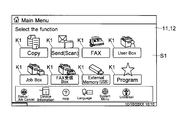
- FIG. 3 is a diagram illustrating an example of the main menu screen S1 displayed on the display panel 11 according to the embodiment.
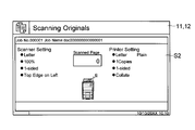
- FIG. 4 is a diagram illustrating an example of a job execution status screen S2 displayed on the display panel 11 according to the embodiment.
- the display panel 11 displays various screens and setting keys.
- the display data for each screen is stored in the storage unit 5 or a memory (not shown) in the operation panel 1.
- the control unit 4 switches the display screen to the display panel 11 in response to an operation on the soft key or the hard key 13 in the setting screen.
- the main menu screen S1 shown in FIG. 3 is the highest screen in the hierarchy.
- the control unit 4 first displays the main menu screen S1 on the display panel 11 when the main power is turned on, when the power saving mode is canceled, or when the job is completed. Icons (images) are arranged on the main menu screen S1. Also, a function selection key K1 for selecting a function (job type) to be used is displayed below each icon. One of the function selection keys K1 can be touched to select a job type such as copy, scan transmission, box storage, and box printing.
- the user When a copy job is to be performed, the user operates the “Copy” function selection key K1.
- the user When performing a scan transmission job for transmitting image data based on data obtained by reading an original, the user operates a function selection key K1 of “Send (Scan)”.
- the control unit 4 When performing a box saving job for storing image data based on data obtained by reading a document in the storage unit 5 (HDD 53) or a box printing job for performing printing based on image data stored in the storage unit 5;
- the user operates the function selection key K1 of “User Box”.
- the control unit 4 causes the display panel 11 to display a screen related to the selected job. The user selects an item so that a desired job result is obtained, and sets a setting value using the selected item.
- the execution status screen S2 is a screen showing the current job execution status.
- FIG. 4 is an example of the copy job execution status screen S2.
- an execution status screen S2 is also prepared for each of other types of jobs such as a print job (printing based on data received from the computer 200), a scan transmission job, a box storage job, and a box print job (illustration is shown). (Omitted).
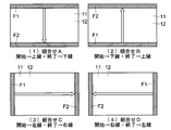
- FIG. 5 shows an example of a combination pattern of the start area F1 and the end area F2.
- the soft key for turning off the power is not displayed on the display panel 11. Instead, the power can be turned off (dropped) by a gesture operation on the touch panel unit 12. Specifically, based on the output of the touch panel unit 12, the control unit 4 is an operation of moving in a predetermined end region direction while touching the predetermined start region F1 while continuing the touch. Recognize the pull operation. Then, the control unit 4 recognizes an operation of sliding the touch position until the touch position reaches the end region F2 by continuing the pull-out operation as a power-off instruction.
- a band-shaped (strip-shaped) region that is in contact with any one of the four end sides of the display region of the display panel 11 and extends along the entire side is defined as the start region F1.
- a band-shaped (strip-shaped) area that is in contact with the side opposite to the side where the start area F1 is provided and extends along the entire opposite side is the end area F2. It is said.
- the widths of the start area F1 and the end area F2 in the direction perpendicular to the side are set to about one-tenth to one-tenth of the length of the short side of the display panel 11.
- the start area F1 and end area F2 do not overlap. In other words, an area that is neither the start area F1 nor the end area F2 is provided between the start area F1 and the end area F2.
- the touch position moves in such a manner that the start area F1 ⁇ the area that is neither the start area F1 nor the end area F2 ⁇ the end area F2.
- the combination A is a combination in which the start area F1 is provided along the upper end side of the display area and the end area F2 is provided along the lower end side of the display area.
- the combination B is a combination in which the start area F1 is provided along the lower end side of the display area and the end area F2 is provided along the upper end side of the display area.
- the combination C is a combination in which the start area F1 is provided along the left end side of the display area and the end area F2 is provided along the right end side of the display area.
- the combination D is a combination in which the start area F1 is provided along the right end side of the display area and the end area F2 is provided along the left end side of the display area.
- the white arrow in each combination diagram of FIG. 5 indicates the direction in which the touch position should be slid when the power is turned off. Note that the start area F1 and the end area F2 do not necessarily need to be in contact with the edge of the display area, and can be determined as appropriate.
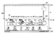
- FIGS. 6 to 8 are diagrams illustrating an example of a display flow when there is no unfinished job on the operation panel 1 according to the embodiment.
- the control unit 4 recognizes the touch of the start area F1, and recognizes an operation of sliding the touch position in the direction of the end area F2 while keeping the touch as a pull-out operation.
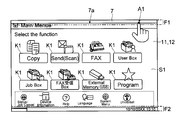
- the controller 4 recognizes the drawer operation, the controller 4 displays the drawer screen 7 on the display panel 11.
- the drawer screen 7 is a screen displayed above (on the uppermost layer) the currently displayed screen. 6 to 8, the screen being displayed (the screen below the drawer screen 7) is the main menu screen S1 (see FIG. 3).
- the control unit 4 increases the area of the drawer screen 7 on the display panel 11 as the drawer operation continues and the amount of movement of the touch position from the start area F1 to the end area increases. At this time, the control unit 4 displays the pull-out screen 7 so as to slide out from the start area F1 (the edge of the display area in contact with the outer side of the start area F1) in accordance with the slide movement direction of the touch position. Display on the panel 11. In other words, the control unit 4 causes the display panel 11 to perform an animation display in which the drawer screen 7 is pulled out like a curtain in accordance with the slide of the touch position.
- the drawer operation is continued, and when the touch position reaches the end area F2, the control unit 4 recognizes that a power-off instruction has been made. Then, the control unit 4 starts a shutdown process (details will be described later). In a state where there is an unprocessed job, even when the touch position reaches the end area F2, the control unit 4 does not recognize that an instruction to turn off the power has been issued and does not perform a shutdown process (details will be described later). .
- combinations B to D differ only in the positional relationship between the combination A, the start area F1, and the end area F2, and the direction in which the drawer screen 7 is drawn (direction indicated by the solid line arrow in FIG. 5).
- the drawer operation is performed on the main menu screen S1
- the drawer screen 7 is displayed by the drawer operation, and the power can be turned off.
- the drawing operations other than the main menu screen S1 and the execution status screen S2 are the same, and illustration and description are omitted.
- FIG. 6 shows the start point of the touch on the start area F1 (a state where the point A1 is touched).
- FIG. 7 shows a state where the touch position is being moved from the point A1 toward the end region F2 (a state where the point A2 is touched).
- FIG. 8 shows an example of a state where the touch position has reached the end region F2 (a state where the touch position is moved to the point A3).
- the movement amount in the vertical direction in the state of FIG. 7 is indicated by M1
- the movement amount in the state of FIG. 8 is indicated by M2.
- the amount of movement (slide amount) of the touch position from the start area F1 toward the end area increases in the order of FIG. 6 ⁇ FIG. 7 ⁇ FIG. Even when the touch position is inclined with respect to the vertical direction, the control unit 4 pays attention only to the component in the vertical direction among the components of the diagonal movement. As shown in FIG. 6 to FIG. 8, the control unit 4 pulls out from the start area F1 toward the end area as the amount of movement of the touch position from the start area F1 toward the end area increases.
- the screen 7 is displayed on the display panel 11.
- the control unit 4 matches the touch position (coordinates) detected by the touch panel unit 12 with the position of the side 7a on the end area side of the drawer screen 7.
- the control unit 4 moves the position of the side 7a on the end area side of the drawer screen 7 so as to be interlocked with the movement of the touch position (as if attached to the fingertip).
- the drawer screen 7 is slid (scrolled) so that the difference (displacement) between the touch position and the position of the side 7a on the end area side of the drawer screen 7 is within a predetermined allowable range.
- the allowable range absolute value can be several millimeters to several centimeters.
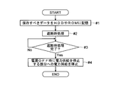
- FIG. 9 is a flowchart illustrating an example of a flow of shutdown processing in the multifunction peripheral 100 according to the embodiment.
- the start of FIG. 9 is a time point when the control unit 4 recognizes that a power-off instruction has been given based on a pull-out operation in a state where there is no unfinished job.
- the control unit 4 stores, in the HDD 53 and the ROM 52, data of a predetermined type (specific data) to be saved among the data stored in the cache memory in the CPU 4a and the RAM 51 (step #). 1). That is, specific data storage processing is performed as one of the shutdown processing. What kind of data is designated as specific data can be determined as appropriate. For example, from the viewpoint of life management of the multifunction device 100 and the members in the multifunction device 100, item values (values used for the total) such as the use time from the power ON to the current time (power OFF), the number of printed sheets, and the number of scanned sheets It may be specific data. Information indicating the state of the multifunction device 100 at the time of power OFF such as the remaining amount of toner may be used as the specific data.
- control unit 4 performs a shutdown process for protecting the storage unit 5 and preventing access to the storage device (step # 2). That is, the shutdown process is performed as one of the shutdown processes.
- the control unit 4 causes the HDD 53 to perform data write / read stop, and magnetic head evacuation as shutdown processing.
- the control unit 4 causes the storage device equipped with the flash memory to stop writing and reading data as the shutdown process.
- Step # 3 Step # 3 No ⁇ Step # 3
- the control unit 4 causes the power supply device 6 to stop power supply to a portion determined to stop power supply when the power is turned off (step # 4). Thereby, the shutdown process is completed, and the power of the multi-function device 100 is turned off (end).
- the multifunction device 100 is provided with a power supply device 6 (see FIG. 2).
- the power supply device 6 receives power from a commercial power source.
- the power supply device 6 includes a rectifier circuit and a voltage conversion circuit, and generates a plurality of types of voltages necessary for the operation of the part included in the multifunction peripheral 100.
- the power supply device 6 supplies power (applies the generated voltage) to each unit of the multifunction peripheral 100 such as the display input device (the operation panel 1 and the control unit 4).
- the power supply device 6 stops the power supply to a predetermined portion when the power supply is stopped when the power is turned off.
- the power can be turned off by a gesture operation (by simply operating the touch panel unit 12). Therefore, it is possible not to provide a switch (hard key) dedicated to power ON / OFF. Therefore, the power supply device 6 changes the omitted power ON / OFF switch to apply a voltage to a part for instructing the power ON of the multifunction peripheral 100 even in the power OFF state.
- the portion for instructing power ON can be determined as appropriate.
- a voltage may be applied to the touch panel unit 12, and it may be detected that an instruction to turn on the power is made by the user based on conduction (signal change, output voltage change) by touching the touch panel unit 12.
- a specific hard key such as a start key or a specific numeric key in the numeric keypad is used as a power ON switch.
- the output signal from the part for instructing power ON is input to the power supply device 6.
- the power supply device 6 starts supplying power to the part that stops power supply when the power is turned off.
- an output signal from a portion for instructing power ON may be input to the control unit 4. In this case, power is supplied only to the portion that detects the power-on instruction of the control unit 4.
- a part of the control unit 4 recognizes the instruction to turn on the power.
- the control unit 4 instructs the power supply device 6 to start the power supply to the portion where the power supply is stopped when the power is turned off. As a result, the multifunction peripheral 100 and the operation panel 1 are turned on.
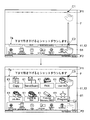
- FIG. 10 is a diagram illustrating an example of a display flow when there is an incomplete job on the operation panel 1 according to the embodiment.
- FIG. 11 is a diagram illustrating an example of a job detail list screen S3 displayed on the display panel 11 according to the embodiment.
- the control unit 4 recognizes the touch of the start area F1, and recognizes an operation of sliding the touch position in the direction of the end area as a pull-out operation while touching.
- the controller 4 displays the drawer screen 7 on the display panel 11.
- the control unit 4 increases the area of the drawer screen 7 on the display panel 11 as the movement amount (slide amount) of the touch position from the start area F1 to the end area F2 increases as the drawer operation is continued. increase.
- the difference between the touch position and the position of the side 7a on the end area side of the drawer screen 7 is set within a predetermined allowable range (matched in the operation panel 1 of the present embodiment). These points are the same as when there is no unfinished job.
- the control unit 4 moves the slide to the end region side of the touch position. Accordingly, the display panel 11 is caused to display the drawing screen 7 until the limit line L1 and the side 7a on the end area side of the drawing screen 7 overlap.
- the control unit 4 changes the end area side 7a of the drawer screen 7 to the end area. Keep away from F2 (do not change the area of the drawer screen 7). Then, the control unit 4 causes the display panel 11 to display a screen in which the side 7a on the end area side of the drawer screen 7 and the position of the restriction line L1 are overlapped. Further, in a state where there are unfinished jobs, the control unit 4 does not recognize that the power-off instruction has been issued even when the touch position reaches the end area F2.
- the limit line L ⁇ b> 1 can be a position separated from the side of the start region F ⁇ b> 1 toward the end region by about 1 ⁇ 2 of the short side or the long side of the display region.
- FIG. 10 illustrates a case where a pull-out operation is performed on the job execution status screen S2 (see FIG. 4).
- the point B1 is illustrated as the first touch point in the start area F1.
- control unit 4 increases the amount of movement (slide amount) of the touch position from the start area F1 toward the end area. 7 is displayed on the display panel 11 so as to be drawn from the start area F1 toward the end area.
- the control unit 4 As shown in the lower diagram of FIG. 10, after the limit line L1 and the side 7a on the end area side of the drawer screen 7 overlap each other (after the touch position reaches the point B2), the control unit 4 However, the area of the drawer screen 7 is not increased even if it is moved in the direction of the end area, and the limit line L1 and the side 7a on the end area side of the drawer screen 7 are kept matched. In a state where there is an uncompleted job, as shown in the lower diagram of FIG. 10, even when the touch position reaches a point B3 in the end area F2, the control unit 4 does not recognize that a power OFF instruction has been given. .
- FIG. 10 shows an example in which the types of uncompleted jobs (copy and box printing) are displayed on the drawer screen 7.
- Information such as the job name and the date and time when the job was input to the multifunction peripheral 100 may be displayed. Thereby, it is possible to recognize what kind of job is being executed or is waiting to be executed.
- the control unit 4 displays a plurality of option keys 8 on the display panel 11. To display. As shown in the upper and lower diagrams of FIG. 10, the display panel 11 displays each option key 8 outside the drawer screen 7. Specifically, in a state where there is an unprocessed job, the drawer screen 7 is drawn only up to the limit line L1, so the control unit 4 displays the option key 8 in the screen on the end area side of the limit line L1.
- a job cancel key 81 When the pull-out operation is performed in the state where there is an unprocessed job, what options are prepared can be determined as appropriate.
- a job cancel key 81 On the operation panel 1 of the present embodiment, a job cancel key 81, an end reservation key 82, and a list display key 83 are displayed as option keys 8.
- the control unit 4 recognizes an operation of moving the touch position in the drawer operation to any of the option keys 8 as an operation of selecting the option key 8. As shown in the upper diagram of FIG. 10, the user slides the touch position to the position of the desired option key 8 while continuing the touch. The control unit 4 performs processing according to the operated option key 8.
- the job cancel key 81 is a key for instructing to cancel the execution of jobs that have not yet been started among jobs that have not been processed. If the job input person confirms whether or not to cancel the job, there is no problem even if the power is turned off. When the job cancel key 81 is selected, the control unit 4 does not execute the unfinished job. Note that data of unfinished jobs may be stored in the storage unit 5 in a nonvolatile manner. Then, when the power is turned on next time, the control unit 4 may cause the printing unit 3, the image reading unit 2 b, and the communication unit 41 to execute the job stored in the storage unit 5.
- control unit 4 may stop the print job halfway.
- the control unit 4 does not feed the next sheet to the sheet feeding unit 3a so that no sheet remains in the transport path when the print job is canceled halfway, and all the fed sheets are put in the discharge tray. After discharging, the printing unit 3 is completely stopped.
- the control unit 4 may cause the communication unit 41 to perform the transmission job until the end, or may cause the communication unit 41 to terminate the transmission job halfway.
- the end reservation key 82 is a key for instructing a power-off reservation so that processing for power-off is started when all jobs are completed.
- the control unit 4 starts a shutdown process when all unfinished jobs are completed (see FIG. 9).
- the list display key 83 is a key for instructing display of a detailed list of jobs that have not been processed.
- the control unit 4 causes the display panel 11 to display a detailed list screen S3 that displays unfinished jobs in a list format (see FIG. 11).
- the control unit 4 causes the display panel 11 to display a detailed list screen S3 including information on jobs that are currently being executed and jobs that are stored in the storage unit 5 and are waiting to be executed. As job information, the type of job, the status of each job, and the name of the job are displayed. In addition, information such as the executor of each job and the date and time when the job is input to the multifunction peripheral 100 may be displayed.
- the control unit 4 recognizes the job corresponding to the touched column as the selected job. Further, when the cancel key K2 is operated while a job is selected, the control unit 4 causes the storage unit 5 to delete data corresponding to the selected job without executing the selected job. Thereby, when it is desired to turn off the power as soon as possible, the execution of a specific job can be stopped.
- FIG. 12 is a diagram illustrating an example of rewinding the drawer screen 7 according to the embodiment.
- the power of the multifunction peripheral 100 and the operation panel 1 can be turned off by moving the touch position from the start area F1 to the end area F2.
- it is desired to cancel the power-off for example, when the user thinks that the power should not be turned off halfway or when the drawer operation is mistakenly performed.
- the touch panel unit 12 receives a cancel operation for canceling the operation for turning off the power. Based on the output of the touch panel unit 12, the control unit 4 recognizes a cancel operation for canceling the operation for turning off the power performed on the touch panel unit 12.
- an operation of releasing a finger from the touch panel unit 12 and an operation of returning the touch position to the start area F1 after the start of the drawer operation and before reaching the end area F2 are accepted as a stop operation.
- the user stops turning off the power after touching the start area F1 the user may remove his / her finger from the touch panel unit 12 or return the touch position to the start area F1.
- the control unit 4 recognizes that the cancel operation has been performed based on the output of the touch panel unit 12. Note that the control unit 4 recognizes the cancel operation in any state where there is an unfinished job and when there is no job.
- the control unit 4 causes the display panel 11 to stop displaying the drawer screen 7. As a result, the entire original screen is displayed (returns to the state before the start of the drawer operation).
- the control unit 4 rewinds the drawer screen 7 as the touch position approaches the start area F1. Reduce the area of 7. In other words, the drawer screen 7 is returned while being slid so that the drawer screen 7 is stored in accordance with the operation of returning the touch position in the direction of the start area F1.
- the upper diagram shows a position (point C2) that is about 1 ⁇ 4 of the vertical length of the display panel 11 from the lower edge of the display panel 11 after touching the point C1 in the start area F1. ) Shows a state where the touch position is slid from top to bottom.
- the touch position is returned from the point C2 to a position (point C3) that is about 1/5 of the vertical length of the display panel 11 from the upper edge of the display panel 11.
- the state (slid) is shown.
- the area of the drawer screen 7 is reduced as the touch position moves upward.
- the side 7a on the end area side of the drawer screen 7 is the touch position so that it matches the slidable touch position (so that the deviation between the touch position and the side 7a on the end area side of the drawer screen 7 is within the allowable range). It is adjusted to move upward.
- the display input device (operation panel 1) includes a setting screen, a display panel 11 for displaying keys, a touch panel unit 12 provided for the display panel 11, and the touch panel unit 12.
- the user's operation content is recognized based on the output of, and a predetermined start area F1 is touched in the display area of the display panel 11, and the predetermined end area is separated from the start area F1. Recognizing a pull-out operation that slides the touch position while continuing the touch toward F2, and recognizing that the touch position reaches the end region F2 due to the continuation of the pull-out operation as a power-off instruction that instructs power-off. And a control unit 4 that performs processing for turning off the power when the OFF instruction is recognized.
- the user can turn off the power only by gesture operation (drawing operation) to the touch panel. Further, it is not necessary to provide a hard key 13 for turning off the power, which is advantageous in terms of manufacturing cost and design of the image forming apparatus (multifunction device 100). Further, it is not necessary to search for the location of the hard key 13 when the power is turned off. Further, it is not necessary to always display the power OFF soft key on the screen of the display panel 11, and the entire display area of the display panel 11 can be used effectively.
- the start area F1 is provided so as to be in contact with any one of the edges of the display area of the display panel 11.
- an end region F2 is provided so as to be in contact with a side opposite to one of the end sides of the display region of the display panel 11.
- the control unit 4 displays the drawer screen 7 superimposed on the currently displayed screen on the display panel 11, and the drawer screen 7 is displayed at the end on the start area F1 side.
- the display area of the pull-out screen 7 is increased as the amount of movement of the touch position from the start of the touch to the start area F1 to the end area increases by causing the display to slide out from the side toward the end area.
- the display panel 11 is gradually increased.
- the power supply cannot be turned off just by accidentally starting the drawer operation. Therefore, even if an erroneous operation is performed, the apparatus is not immediately turned off, and a display input apparatus (operation panel 1) that is easy to use can be provided. In addition, the user can visually recognize how much the touch position should be moved after the start of the pull-out operation until the power-off is accepted. Therefore, an input for instructing the power OFF intuitively and intuitively can be performed.
- the job will end in the middle, and paper jams will occur in the image forming apparatus (multifunction device 100). Also, if there is a job waiting for execution (waiting) and the power is turned off, the job waiting for execution remains unexecuted. The power OFF should not be performed ignoring the intention of the user who wants to execute the job.
- the control unit 4 displays the unprocessed job in the extraction screen 7. As a result, it is possible to confirm whether or not there is a job at the present time when the power is turned off. Therefore, the user can easily recognize the reason why the power supply should not be turned off.
- control unit 4 sets the difference between the touch position and the position of the side 7a on the end area side of the drawer screen 7 within a predetermined allowable range when the drawer operation is performed in the state where there is no unfinished job.
- the display area of the drawer screen 7 is gradually increased on the display panel 11 as the amount of movement of the touch position in the direction of the end region increases. Then, when the drawer operation is performed in a state where there is an unprocessed job, the control unit 4 determines that the touch position and the edge 7a on the end area side of the drawer screen 7 reach the predetermined limit line L1.
- the display of the drawer screen 7 is increased as the amount of movement of the touch position in the direction of the end area in the drawer operation increases.
- the area is gradually increased on the display panel 11, and after reaching the limit line L1, the display of the drawer screen 7 up to the limit line L1 is continued on the display panel 11 even if the touch position is moved further toward the end region. Even if the position reaches the end region F2, it is not recognized that a power OFF instruction has been issued.
- the drawer screen 7 can be pulled out only halfway, so that the user can perceive that the power cannot be turned off.
- the control unit 4 includes a job cancel key 81 for instructing to stop job execution that has not been started among unprocessed jobs, and an unprocessed job.
- End reservation key 82 for instructing reservation of power OFF so that processing for power OFF is started when all completed jobs are completed, and a list for instructing display of a detailed list of unprocessed jobs At least one of the display keys 83 is displayed on the display panel 11 as the option key 8 and processing corresponding to the selected option key 8 is performed.
- the job execution can be stopped by the job stop key 81 so that the power can be turned off immediately.
- the end reservation key 82 can be used to make a reservation for turning off the power after all jobs are completed. Therefore, it is not necessary to perform the operation for turning off the power again after the time for completing all jobs is completed.
- the list display key 83 can also be used to confirm details of a job that has not been processed.
- the display panel 11 displays the option key 8 outside the drawer screen 7.
- the control unit 4 recognizes the operation of moving the touch position in the drawer operation to any of the option keys 8 as the operation of selecting the option key 8. As a result, it is possible to select the option key 8 displayed when the power cannot be turned off because there is a job that has not been processed by an extremely simple operation, which is an operation subsequent to the pull-out operation.
- control unit 4 displays the drawing screen 7 so that the drawer screen 7 is slid and stored on the edge on the start area F1 side after the drawer operation, thereby increasing the return amount of the touch position in the direction of the start area F1. Accordingly, the display area of the drawer screen 7 is gradually reduced to the display panel 11, and when the touch position is returned to the start area F1 or when the touch is released before reaching the end position, the drawer is pulled out. The display on the screen 7 is stopped on the display panel 11.
- the image forming apparatus includes a storage unit 5 (RAM 51, ROM 52, HDD 53) that stores data, a display input device (operation panel 1), and a power supply unit 6 that supplies power to the storage unit 5.
- the display input device is included.
- the control unit 4 recognizes the power-off instruction, the control unit 4 causes the storage unit 5 to perform a shutdown process, which is a process for protecting stored data, and the power supply device 6 performs a shutdown process such as a shutdown process. Is completed, the power supply to the part where the power supply is stopped when the power is turned off is stopped.
- an image forming apparatus (multifunction apparatus 100) that does not require searching for the location of the hard key 13 when the power is turned off, or providing the hard key 13 for turning off the power. Further, it is possible to provide an image forming apparatus that can safely and easily turn off the power.
- the present invention can be used for a display input device and an image forming apparatus including the display input device.
Landscapes
- Engineering & Computer Science (AREA)
- General Engineering & Computer Science (AREA)
- Theoretical Computer Science (AREA)
- Human Computer Interaction (AREA)
- Multimedia (AREA)
- Signal Processing (AREA)
- Physics & Mathematics (AREA)
- General Physics & Mathematics (AREA)
- Facsimiles In General (AREA)
- User Interface Of Digital Computer (AREA)
- Accessory Devices And Overall Control Thereof (AREA)
Abstract
Description
図1、図2に基づき、実施形態に係る複合機100の概略を説明する。図1、図2は、実施形態に係る複合機100の一例を示す図である。
次に、図3、図4を用いて実施形態に係る表示パネル11で表示される画面の一例を説明する。図3は、実施形態に係る表示パネル11に表示されるメインメニュー画面S1の一例を示す図である。図4は、実施形態に係る表示パネル11に表示されるジョブの実行状況画面S2の一例を示す図である。
次に、本実施形態の操作パネル1で定められる開始領域F1と終了領域F2について説明する。図5は、開始領域F1と終了領域F2の組合せパターンの一例を示す。
次に、図6~図8を用いて、実施形態に係る操作パネル1で、処理未完了のジョブが無いときの表示の流れを説明する。図6~図8は、実施形態に係る操作パネル1で、処理未完了のジョブが無いときの表示の流れの一例を示す図である。
次に、図9を用いて、実施形態に係る複合機100でのシャットダウン処理の流れの一例を説明する。図9は、実施形態に係る複合機100でのシャットダウン処理の流れの一例を示すフローチャートである。
次に、図10、図11を用いて、実施形態に係る操作パネル1で、処理未完了のジョブがあるときの表示の流れを説明する。図10は、実施形態に係る操作パネル1で、処理未完了のジョブがあるときの表示の流れの一例を示す図である。図11は、実施形態に係る表示パネル11に表示されるジョブの詳細リスト画面S3の一例を示す図である。
次に、図12を用いて、実施形態に係る引出画面7の巻き戻しと電源OFFの中止を説明する。図12は、実施形態に係る引出画面7の巻き戻しの一例を示す図である。
Claims (10)
- 設定用の画面、キーを表示する表示パネルと、
前記表示パネルに対して設けられたタッチパネル部と、
前記タッチパネル部の出力に基づき使用者の操作内容を認識し、前記表示パネルの表示領域のうち予め定められた開始領域をタッチし、前記開始領域とは離れた領域であって予め定められた領域である終了領域に向けてタッチを続けたままタッチ位置をスライド移動させる引出操作を認識し、前記引出操作の継続によるタッチ位置の前記終了領域への到達を電源のOFFを指示する電源OFF指示と認識し、前記電源OFF指示を認識したとき電源OFFのための処理を行わせる制御部と、を含むことを特徴とする表示入力装置。 - 前記表示パネルの表示領域の端辺のうちのいずれかの1辺に接するように前記開始領域を設け、
前記表示パネルの表示領域の端辺のうち、前記1辺に対向する辺に接するように前記終了領域を設け、
前記制御部は、前記開始領域へのタッチの後、前記引出操作がなされると、表示中の画面上に重ねられる引出画面を前記表示パネルに表示させ、前記引出画面が前記開始領域側の端辺から前記終了領域方向に向けてスライドして引き出されるように表示させることによって、前記開始領域へのタッチ開始から前記終了領域方向へのタッチ位置の移動量が多くなるのに従い前記引出画面の表示面積を前記表示パネルに次第に増加させることを特徴とする請求項1に記載の表示入力装置。 - 処理未完了のジョブがある状態で前記引出操作がなされたとき、
前記制御部は、処理未完了のジョブの情報を前記引出画面内に表示させることを特徴とする請求項2に記載の表示入力装置。 - 前記制御部は、
処理未完了のジョブがない状態で前記引出操作がなされた場合、タッチ位置と前記引出画面の前記終了領域側の辺の位置との差を予め定められた許容範囲内としつつ、前記終了領域方向へのタッチ位置の移動量が多くなるのに従って前記引出画面の表示面積を表示パネルに次第に増加させ、
処理未完了のジョブがある状態で前記引出操作がなされた場合、前記引出画面の終了領域側の辺が予め定められた制限ラインに到るまでは、タッチ位置と前記引出画面の前記終了領域側の辺の位置との差を予め定められた許容範囲内としつつ、前記引出操作での前記終了領域方向へのタッチ位置の移動量が多くなるのに従って前記引出画面の表示面積を表示パネルに次第に増加させ、前記制限ラインに到った後、さらに前記終了領域方向にタッチ位置が移動されても前記制限ラインまでの前記引出画面の表示を前記表示パネルに続けさせ、タッチ位置が前記終了領域に到達しても前記電源OFF指示がなされたとは認識しないことを特徴とする請求項2に記載の表示入力装置。 - 処理未完了のジョブがある状態で前記引出操作がなされたとき、
前記制御部は、処理未完了のジョブのうち、まだ開始されていないジョブ実行中止を指示するジョブ中止キーと、処理未完了の全ジョブが完了すると電源OFFのための処理が開始されるように電源OFFの予約を指示するための終了予約キーと、処理未完了のジョブの詳細リストの表示を指示するためのリスト表示キーのうち、少なくとも1つを選択肢キーとして前記表示パネルに表示させ、選ばれた選択肢キーに応じた処理を行うことを特徴とする請求項2に記載の表示入力装置。 - 前記表示パネルは、前記選択肢キーを前記引出画面外に表示し、
前記制御部は、前記引出操作でのタッチ位置を何れかの選択肢キーまで移動させる操作を、選択肢キーを選ぶ操作と認識することを特徴とする請求項5に記載の表示入力装置。 - 前記リスト表示キーが操作されたとき、前記制御部は処理未完了のジョブを一覧形式で表示し、中止キーが設けられた詳細リスト画面を前記表示パネルに表示させ、
前記詳細リスト画面内の何れかの欄がタッチされたとき、前記制御部はタッチされた欄に対応するジョブを選択されたジョブと認識し、ジョブが選択された状態で前記中止キーが操作されたとき、選択されたジョブを実行せず、選択されたジョブに対応するデータを消去させることを特徴とする請求項5に記載の表示入力装置。 - 前記制御部は、前記引出操作後、前記引出画面が前記開始領域側の端辺にスライドして収納されていくように表示させることによって、前記開始領域方向へのタッチ位置の戻し量が多くなるのに従い、前記引出画面の表示面積を前記表示パネルに次第に減少させ、また、タッチ位置が前記開始領域まで戻されたとき、又は、前記終了位置に到る前にタッチが離されたとき、前記引出画面の表示を前記表示パネルに止めさせることを特徴とする請求項2に記載の表示入力装置。
- 請求項1に記載の表示入力装置と、
データを記憶する記憶部と、
前記表示入力装置及び前記記憶部に電力を供給する電源装置と、を含み、
前記制御部は、前記電源OFF指示を認識したとき、記憶されたデータを保護するための処理であるシャットダウン処理を前記記憶部に行わせ、
前記電源装置は、前記シャットダウン処理が完了した後、電源OFF時に電力供給を停止する部分への電力供給を停止することを特徴とする画像形成装置。 - 設定用の画面、キーを表示パネルに表示させ、
前記表示パネルに対して設けられたタッチパネル部の出力に基づき使用者の操作内容を認識し、
前記表示パネルの表示領域のうち予め定められた開始領域をタッチし、前記開始領域とは離れた領域であって予め定められた領域である終了領域に向けてタッチを続けたままタッチ位置をスライド移動させる引出操作を認識し、
前記引出操作の継続によるタッチ位置の前記終了領域への到達を電源のOFFを指示する電源OFF指示と認識し、
前記電源OFF指示を認識したとき電源OFFのための処理を行うことを特徴とする表示入力装置の制御方法。
Priority Applications (2)
| Application Number | Priority Date | Filing Date | Title |
|---|---|---|---|
| US15/543,337 US10338804B2 (en) | 2015-02-06 | 2015-12-15 | Display input device, image formation device comprising same, and control method for display input device |
| JP2016573202A JP6388037B2 (ja) | 2015-02-06 | 2015-12-15 | 表示入力装置及びこれを備えた画像形成装置、表示入力装置の制御方法 |
Applications Claiming Priority (2)
| Application Number | Priority Date | Filing Date | Title |
|---|---|---|---|
| JP2015022440 | 2015-02-06 | ||
| JP2015-022440 | 2015-02-06 |
Publications (1)
| Publication Number | Publication Date |
|---|---|
| WO2016125401A1 true WO2016125401A1 (ja) | 2016-08-11 |
Family
ID=56563758
Family Applications (1)
| Application Number | Title | Priority Date | Filing Date |
|---|---|---|---|
| PCT/JP2015/085099 Ceased WO2016125401A1 (ja) | 2015-02-06 | 2015-12-15 | 表示入力装置及びこれを備えた画像形成装置、表示入力装置の制御方法 |
Country Status (3)
| Country | Link |
|---|---|
| US (1) | US10338804B2 (ja) |
| JP (1) | JP6388037B2 (ja) |
| WO (1) | WO2016125401A1 (ja) |
Cited By (1)
| Publication number | Priority date | Publication date | Assignee | Title |
|---|---|---|---|---|
| CN111488064A (zh) * | 2019-01-25 | 2020-08-04 | 富士施乐株式会社 | 信息处理装置和计算机可读记录介质 |
Families Citing this family (2)
| Publication number | Priority date | Publication date | Assignee | Title |
|---|---|---|---|---|
| JP6693073B2 (ja) * | 2015-09-14 | 2020-05-13 | セイコーエプソン株式会社 | 機器による装置の取扱説明方法、機器およびプログラム |
| JP7321021B2 (ja) * | 2019-07-26 | 2023-08-04 | シャープ株式会社 | 画像形成装置およびデータ保護方法 |
Citations (5)
| Publication number | Priority date | Publication date | Assignee | Title |
|---|---|---|---|---|
| JP2006080855A (ja) * | 2004-09-09 | 2006-03-23 | Konica Minolta Business Technologies Inc | データ管理装置、画像出力装置、データ管理方法、およびコンピュータプログラム |
| JP2010183244A (ja) * | 2009-02-04 | 2010-08-19 | Fujifilm Corp | 撮像装置及び撮像装置の制御方法 |
| JP2012155743A (ja) * | 2012-04-11 | 2012-08-16 | Sony Computer Entertainment Inc | 情報処理装置 |
| JP2014085980A (ja) * | 2012-10-26 | 2014-05-12 | Dainippon Printing Co Ltd | 表示機能およびタッチ入力機能を有するカード媒体 |
| JP2014177024A (ja) * | 2013-03-14 | 2014-09-25 | Konica Minolta Inc | ジョブ処理装置、ジョブ用画面表示方法、およびコンピュータプログラム |
Family Cites Families (3)
| Publication number | Priority date | Publication date | Assignee | Title |
|---|---|---|---|---|
| JP4125269B2 (ja) | 2004-07-09 | 2008-07-30 | キヤノン株式会社 | ジョブ処理システム及びその制御方法 |
| US20090199093A1 (en) * | 2007-09-04 | 2009-08-06 | Tridib Chakravarty | Image Capture And Sharing System and Method |
| JP5708555B2 (ja) * | 2012-04-25 | 2015-04-30 | コニカミノルタ株式会社 | 操作表示装置及び操作表示方法プログラム |
-
2015
- 2015-12-15 JP JP2016573202A patent/JP6388037B2/ja not_active Expired - Fee Related
- 2015-12-15 WO PCT/JP2015/085099 patent/WO2016125401A1/ja not_active Ceased
- 2015-12-15 US US15/543,337 patent/US10338804B2/en active Active
Patent Citations (5)
| Publication number | Priority date | Publication date | Assignee | Title |
|---|---|---|---|---|
| JP2006080855A (ja) * | 2004-09-09 | 2006-03-23 | Konica Minolta Business Technologies Inc | データ管理装置、画像出力装置、データ管理方法、およびコンピュータプログラム |
| JP2010183244A (ja) * | 2009-02-04 | 2010-08-19 | Fujifilm Corp | 撮像装置及び撮像装置の制御方法 |
| JP2012155743A (ja) * | 2012-04-11 | 2012-08-16 | Sony Computer Entertainment Inc | 情報処理装置 |
| JP2014085980A (ja) * | 2012-10-26 | 2014-05-12 | Dainippon Printing Co Ltd | 表示機能およびタッチ入力機能を有するカード媒体 |
| JP2014177024A (ja) * | 2013-03-14 | 2014-09-25 | Konica Minolta Inc | ジョブ処理装置、ジョブ用画面表示方法、およびコンピュータプログラム |
Non-Patent Citations (1)
| Title |
|---|
| TOMOMI NAKAMURA ET AL., IPHONE 5S & IPHONE 5C GENIUS GUIDE, 28 September 2013 (2013-09-28), pages 32 * |
Cited By (4)
| Publication number | Priority date | Publication date | Assignee | Title |
|---|---|---|---|---|
| CN111488064A (zh) * | 2019-01-25 | 2020-08-04 | 富士施乐株式会社 | 信息处理装置和计算机可读记录介质 |
| JP2020119377A (ja) * | 2019-01-25 | 2020-08-06 | 富士ゼロックス株式会社 | 情報処理装置及びプログラム |
| JP7310152B2 (ja) | 2019-01-25 | 2023-07-19 | 富士フイルムビジネスイノベーション株式会社 | 情報処理装置及びプログラム |
| CN111488064B (zh) * | 2019-01-25 | 2024-07-26 | 富士胶片商业创新有限公司 | 信息处理装置和计算机可读记录介质 |
Also Published As
| Publication number | Publication date |
|---|---|
| US20180004387A1 (en) | 2018-01-04 |
| JP6388037B2 (ja) | 2018-09-12 |
| US10338804B2 (en) | 2019-07-02 |
| JPWO2016125401A1 (ja) | 2017-10-26 |
Similar Documents
| Publication | Publication Date | Title |
|---|---|---|
| CN102568019B (zh) | 可容易地编辑预览图像的图像编辑装置 | |
| JP6338318B2 (ja) | 操作装置、画像形成装置及びコンピュータプログラム | |
| JP5923477B2 (ja) | 表示入力装置、画像形成装置 | |
| CN108513029B (zh) | 图像处理装置和图像处理装置的控制方法 | |
| JP2013115524A (ja) | 画像形成装置 | |
| JP6388037B2 (ja) | 表示入力装置及びこれを備えた画像形成装置、表示入力装置の制御方法 | |
| US9148534B2 (en) | Display input device to display preview and default setting images, image forming apparatus, control method for display input device | |
| JP6002650B2 (ja) | 表示入力装置及びこれを備えた画像形成装置 | |
| CN105721732B (zh) | 显示输入装置、图像形成装置、显示输入装置的控制方法 | |
| JP6079659B2 (ja) | 表示システム、画像形成装置、プログラム、表示状態制御方法 | |
| US10712911B2 (en) | Display input device, image forming device, and method for controlling display input device | |
| JP2013141196A (ja) | 画像形成装置及び画像形成システム | |
| US11765287B2 (en) | Information processing apparatus capable of allowing display device to display combinations of setting values satisfying predetermined condition | |
| US10209860B2 (en) | Display input device capable of detecting operation performed on display portion, image processing apparatus, display input method | |
| JP6380338B2 (ja) | 表示入力装置およびそれを備えた画像形成装置 | |
| JP7000977B2 (ja) | 画像形成装置 | |
| US10757278B2 (en) | Image forming apparatus that executes first job and second job in parallel | |
| JP5364665B2 (ja) | 画像形成装置 | |
| JP5793604B2 (ja) | 表示入力装置及びこれを備えた画像形成装置 | |
| JP5858582B2 (ja) | 表示入力装置および画像形成装置 | |
| JP2017204114A (ja) | 画像処理装置、画像処理装置の機能設定方法 |
Legal Events
| Date | Code | Title | Description |
|---|---|---|---|
| 121 | Ep: the epo has been informed by wipo that ep was designated in this application |
Ref document number: 15881218 Country of ref document: EP Kind code of ref document: A1 |
|
| WWE | Wipo information: entry into national phase |
Ref document number: 15543337 Country of ref document: US |
|
| ENP | Entry into the national phase |
Ref document number: 2016573202 Country of ref document: JP Kind code of ref document: A |
|
| NENP | Non-entry into the national phase |
Ref country code: DE |
|
| 122 | Ep: pct application non-entry in european phase |
Ref document number: 15881218 Country of ref document: EP Kind code of ref document: A1 |