WO2016121653A1 - 吸気整流装置、これを備えたコンプレッサ - Google Patents
吸気整流装置、これを備えたコンプレッサ Download PDFInfo
- Publication number
- WO2016121653A1 WO2016121653A1 PCT/JP2016/051897 JP2016051897W WO2016121653A1 WO 2016121653 A1 WO2016121653 A1 WO 2016121653A1 JP 2016051897 W JP2016051897 W JP 2016051897W WO 2016121653 A1 WO2016121653 A1 WO 2016121653A1
- Authority
- WO
- WIPO (PCT)
- Prior art keywords
- intake
- flow guide
- compressor
- silencer
- cover ring
- Prior art date
Links
Images


Classifications
-
- F—MECHANICAL ENGINEERING; LIGHTING; HEATING; WEAPONS; BLASTING
- F02—COMBUSTION ENGINES; HOT-GAS OR COMBUSTION-PRODUCT ENGINE PLANTS
- F02B—INTERNAL-COMBUSTION PISTON ENGINES; COMBUSTION ENGINES IN GENERAL
- F02B37/00—Engines characterised by provision of pumps driven at least for part of the time by exhaust
-
- F—MECHANICAL ENGINEERING; LIGHTING; HEATING; WEAPONS; BLASTING
- F02—COMBUSTION ENGINES; HOT-GAS OR COMBUSTION-PRODUCT ENGINE PLANTS
- F02B—INTERNAL-COMBUSTION PISTON ENGINES; COMBUSTION ENGINES IN GENERAL
- F02B39/00—Component parts, details, or accessories relating to, driven charging or scavenging pumps, not provided for in groups F02B33/00 - F02B37/00
-
- F—MECHANICAL ENGINEERING; LIGHTING; HEATING; WEAPONS; BLASTING
- F04—POSITIVE - DISPLACEMENT MACHINES FOR LIQUIDS; PUMPS FOR LIQUIDS OR ELASTIC FLUIDS
- F04D—NON-POSITIVE-DISPLACEMENT PUMPS
- F04D29/00—Details, component parts, or accessories
- F04D29/40—Casings; Connections of working fluid
- F04D29/42—Casings; Connections of working fluid for radial or helico-centrifugal pumps
- F04D29/44—Fluid-guiding means, e.g. diffusers
-
- Y—GENERAL TAGGING OF NEW TECHNOLOGICAL DEVELOPMENTS; GENERAL TAGGING OF CROSS-SECTIONAL TECHNOLOGIES SPANNING OVER SEVERAL SECTIONS OF THE IPC; TECHNICAL SUBJECTS COVERED BY FORMER USPC CROSS-REFERENCE ART COLLECTIONS [XRACs] AND DIGESTS
- Y02—TECHNOLOGIES OR APPLICATIONS FOR MITIGATION OR ADAPTATION AGAINST CLIMATE CHANGE
- Y02T—CLIMATE CHANGE MITIGATION TECHNOLOGIES RELATED TO TRANSPORTATION
- Y02T10/00—Road transport of goods or passengers
- Y02T10/10—Internal combustion engine [ICE] based vehicles
- Y02T10/12—Improving ICE efficiencies
Definitions
- the present invention relates to an intake air rectifier and a compressor including the same.
- Patent Document 1 discloses a supercharger including a compressor and a filter (intake silencer) connected to the intake air inlet passage side of the compressor.
- an exclusive flow guide 104 is interposed between the intake silencer 101 and the intake passage 103 of the compressor 102, whereby intake air from the intake silencer 101.
- the flow to the passage 103 is arranged.
- the flow guide 104 has a large length in the axial direction and is made of cast metal, and has a thickness of about 12 to 20 mm and is heavy, the supercharger (compressor 102) is opened and assembled. The workability in etc. was bad.
- the present invention has been made in view of such circumstances, and has a structure that is compact, lightweight, and easy to manufacture, and matches the shape of the flow path from the intake silencer to the compressor intake passage to the specifications of the turbocharger. It is an object of the present invention to provide an intake air rectifier that can be appropriately selected and a compressor including the intake rectifier.
- the present invention employs the following means.
- An intake air rectifier is provided in an intake passage between a compressor in a supercharger and an intake silencer connected to an intake gas inlet side of the compressor, and is provided in the intake silencer.
- a flow guide whose inner diameter decreases from the intake silencer side toward the compressor side, a cover ring provided between the flow guide and the compressor, and connecting the flow guide and the intake passage; It is equipped with.
- the gas that has passed through the silencer element inside the intake silencer passes through the flow guide provided in the intake silencer and the cover ring connected to the downstream side thereof, and is then rectified. Is sucked into the intake passage.
- the above rectifying action can be appropriately changed according to the specifications of the supercharger by replacing the cover ring with a different shape.
- the cover ring forms a flow path by being connected to the downstream side of the flow guide provided in the intake silencer. For this reason, as a member of the intake air rectifier that is changed according to the specifications of the turbocharger, a large and heavy one that is connected integrally from the intake silencer to the intake passage of the compressor, such as a conventional flow guide made of casting Compared to, it is smaller and lighter.
- the miniaturized cover ring does not require a large space in its storage location. For this reason, a large number of cover rings can be prepared and appropriately selected according to the specifications of the supercharger. Furthermore, even if the cover ring is manufactured by casting, the wooden mold is reduced in size, so that the wooden mold can be easily stored.
- the small, lightweight, and easy-to-manufacture structure allows the flow path shape from the intake silencer to the compressor intake passage to be appropriately selected according to the supercharger specifications.
- a gap may be provided between the downstream end of the flow guide and the upstream end of the cover ring.
- the cover ring is preferably manufactured by casting with excellent manufacturability, but there is a concern that dimensional errors may occur due to casting, so by providing a gap with the flow guide as described above, especially when installing an intake silencer An error in the axial position can be allowed.
- a step may be formed at an end of the cover ring on the intake silencer side, and a downstream end of the flow guide may be fitted into the step.
- the intake silencer can be positioned by fitting the flow guide into the cover ring when installing the intake silencer to the compressor, making it easy to install the intake silencer. can do.
- the flow guide is preferably formed of a metal plate and integrated with the intake silencer.
- the weight of the flow guide can be drastically reduced as compared with the case of conventional casting, and the support structure can be simplified, so that the cost around the intake silencer can be reduced. .
- the compressor impeller because the flow guide made of metal plate has ductility, the compressor impeller, called a burst, should be damaged during operation of the turbocharger, and the broken fragments of the compressor impeller scattered in the axial and radial directions. If the flow guide collides with the flow guide, the impact is absorbed or alleviated by plastic deformation of the flow guide. Therefore, safety can be improved.
- the upstream end of the flow guide may be expanded. Thereby, the rectification effect of the airflow flowing into the flow guide from the inside of the intake silencer can be enhanced.
- the compressor according to the present invention includes any one of the intake rectifiers described above. For this reason, the cover ring is reduced in size and weight so that a large number of types can be easily arranged, and the structure from the intake silencer to the compressor intake passage is supercharged with a small, lightweight, and easy-to-manufacture structure. It can be selected appropriately according to the specifications of the machine.
- the flow path shape from the intake silencer to the compressor intake passage is supercharged by a small, lightweight, and easily manufactured structure. It can be selected appropriately according to the specifications of the machine.
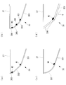
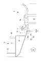
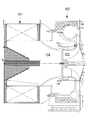
- FIG. 1 is a longitudinal sectional view showing a vicinity of a compressor and an intake silencer of a turbocharger to which an intake rectifier according to an embodiment of the present invention is applied. It is the longitudinal cross-sectional view which expands the II section of FIG. 1 and shows 1st Embodiment of the intake rectifier which concerns on this invention. It is the III section enlarged view of Drawing 2, and (a), (b), (c), and (d) are longitudinal sections showing the example of the shape of the flow guide upstream end, respectively. It is a longitudinal cross-sectional view which shows 2nd Embodiment of the intake rectifier which concerns on this invention. It is the V section enlarged view of FIG. It is a longitudinal cross-sectional view which shows the compressor and intake silencer vicinity of the supercharger which shows the prior art.
- FIG. 1 is a longitudinal sectional view showing a compressor 2 of a supercharger 1 to which an intake air rectifier according to the present invention is applied, and the vicinity of an intake silencer 3 connected to the compressor 2.
- the supercharger 1 of this embodiment is a device that increases the combustion efficiency of an internal combustion engine by compressing a gas such as air or gas supplied to the internal combustion engine and guiding the compressed gas to the internal combustion engine.
- the compressor 2 is provided adjacent to the bearing base 4, and the turbine shaft 5 pivotally supported by a bearing (not shown) inside the bearing base 4 is passed through the casing 6 of the compressor 2.
- a compressor impeller 7 is fixed to an end of the turbine shaft 5 so as to rotate integrally.
- the compressor impeller 7 has a configuration in which a large number of fins (blades) 7 b project from the outer peripheral surface of a hub 7 a that forms the center thereof, and rotates inside the casing 6.
- An exhaust turbine (not shown) is installed on the opposite side of the bearing stand 4 with respect to the compressor 2, and a turbine impeller (not shown) is fixed to the other end of the turbine shaft 5 so as to rotate integrally.
- an intake passage 10 along the axial direction of the turbine shaft 5, a stationary vane-shaped diffuser 11, a spiral scroll passage 12, and a compressed gas outlet 13 are provided.
- the casing 6 includes, for example, an inner housing 6 a that forms the intake passage 10, a middle housing 6 b that forms the inner peripheral surface of the scroll passage 12, and an outer housing 6 c that forms the outer peripheral surface of the scroll passage 12. 7 is accommodated in the inner housing 6a (intake passage 10).
- a heat insulating material 15 is attached to the outer peripheral portion of the outer housing 6c.
- An annular cover ring 20 constituting an intake rectifier 18 according to an embodiment of the present invention described later is detachably fixed by a plurality of bolts 19 on the inlet side (intake silencer 3 side) of the inner housing 6a.
- the intake silencer 3 connects, for example, a disk-shaped front panel 21, a rear panel 22 that is opposed to the front panel 21 and has a communication hole 22 a in the center, and the periphery of the panels 21 and 22.
- the outer peripheral panel 23 provided in this way is a cylindrical shape assembled.
- a silencer element 25 is provided along the inner peripheral surface of the outer peripheral panel 23, and a guide cylinder 26 is installed along the central axis of the intake silencer 3.
- the guide tube 26 has a conical shape whose inner diameter decreases from the front panel 21 side toward the rear panel 22 (communication hole 22a) side.
- An outlet pipe 27 extending to the compressor 2 side is inserted into and fixed to the communication hole 22 a of the rear panel 22, and a mounting flange 28 fixed to the outer periphery of the end of the outlet pipe 27 on the compressor 2 side is a casing with a plurality of bolts 29.
- the intake silencer 3 is connected and fixed to the casing 6.
- a conical tubular flow guide 30 constituting the intake air rectifier 18 according to the embodiment of the present invention is installed on the inner peripheral portion of the outlet pipe 27.
- a sound insulating material 32 is disposed between the inner surfaces of the front panel 21 and the rear panel 22, the inside of the guide tube 26, and between the outlet pipe 27 and the flow guide 30, respectively.
- FIG. 2 is a longitudinal cross-sectional view showing the first embodiment of the intake air rectifier 18 by enlarging the II part of FIG.
- the intake air rectifier 18 is provided between the intake silencer 3 and the intake passage 10 of the compressor 2, and gas A such as air drawn from the outer periphery of the intake silencer 3 is aligned along the central axis of the intake passage 10. The flow is rectified to flow into the intake passage 10.
- the intake air rectifier 18 is provided on the annular cover ring 20 detachably fixed to the inlet side of the inner housing 6a with a plurality of bolts 19 and the inner peripheral portion of the outlet pipe 27 of the intake silencer 3. And a conical tubular flow guide 30.
- the flow guide 30 that forms the intake outlet portion of the intake silencer 3 has a conical tubular shape whose inner diameter decreases from the intake silencer 3 side toward the intake passage 10 side (cover ring 20 side), and constitutes each part of the intake silencer 3. It is formed of a metal plate similar to a rolled steel plate or the like (for example, Gr. C or Gr. D of ASTM standard A283) and integrated with the intake silencer 3.
- the end of the flow guide 30 on the intake silencer 3 side is welded to the inner periphery of the front end of the outlet pipe 27, and the end of the flow guide 30 on the intake passage 10 side is connected to the rear of the outlet pipe 27 via the rear end plate 34. It is fixed at the end.
- the cover ring 20 is an annular member positioned between the flow guide 30 and the intake passage 10 (inner housing 6 a) of the compressor 2, and a plurality of bolts 19 are attached to the inner housing 6 a forming the intake passage 10. It is concluded with.
- the inner peripheral surface of the inner housing 6a is substantially extended to the flow guide 30 side.
- the inner diameter of the cover ring 20 gradually decreases from the flow guide 30 side toward the intake passage 10 side, and the downstream end portion 30a inner peripheral surface of the flow guide 30 and the upstream end inner peripheral surface 10a of the intake passage 10 Is smoothly connected without any step.
- the cover ring 20 is preferably cast from cast iron (for example, Gr. 65-45-12 of ASTM standard A536, FCD450 of JIS standard) constituting the casing 6 of the compressor 2, etc. It may be manufactured.
- a small gap C between the downstream end 30a of the flow guide 30 and the end of the cover ring 20 on the intake silencer 3 side so as not to disturb the flow of the gas A.
- the size of the gap C is preferably set in a range of about 3 mm to 5 mm, for example.
- the upstream end of the flow guide 30 is expanded in a funnel shape (funnel shape or trumpet shape).
- a funnel shape French shape or trumpet shape.
- FIGS. 3A to 3D As the expanded shape (structure), those shown in FIGS. 3A to 3D can be exemplified.
- the flow guide 30 is constituted by three metal plates 301, 302, and 303, and the abutting portion is welded by two welding lines W1 and W2 to form an expanded shape.
- the flow guide 30 is composed of four metal plates 301, 304, 305, and 306, and the abutting portion is welded by three welding lines W3, W4, and W5 to expand the shape. It is said.
- the flow guide 30 is composed of one metal plate 301 and one metal plate 307 having a curved surface, and the butted portion is welded by one welding line W6. Open shape.
- 3D shows that the flow guide 30 is composed of two metal plates 301 and 308, the abutting portions are welded by one welding line W7, and the corner portions of the metal plates 301 and 308 are The shape is expanded by grinding with a grinder or the like from the circumferential side to the position of the line G.
- exhaust gas from the high-temperature and high-pressure internal combustion engine flows into an exhaust turbine (not shown) of the supercharger 1, and this exhaust gas rotationally drives a turbine impeller (not shown).
- the turbine shaft 5 and the compressor impeller 7 rotate integrally.
- the above rectifying action can be appropriately changed according to the specifications of the supercharger 1 by replacing the cover ring 20 with a different shape.
- the flow guide 30 does not need to be changed according to the specifications of the supercharger 1.
- FIG. 2 when the shape of the inner housing 6a is changed and the inner diameter of the intake passage 10 is reduced to the shape of 10b indicated by a two-dot chain line, the shape of the cover ring 20 indicated by reference numeral 20a is formed. Replace with one.
- the inner diameter of the end of the cover ring 20a on the intake silencer 3 side is the same as the inner peripheral surface of the end portion 30a of the flow guide 30, and the inner diameter of the end of the cover ring 20a on the intake passage 10 side is reduced.
- the inner diameter of the inner housing 6a is adjusted to the inner diameter.
- the gas A that has passed through the intake passage 10 is compressed by the compressor impeller 7, is then discharged from the compressed gas outlet 13 through the diffuser 11 and the spiral scroll passage 12, and is supplied to an internal combustion engine (not shown).
- the cover ring 20 is connected to the downstream side of the flow guide 30 integrated with the intake silencer 3 to form a flow path. For this reason, as a member of the intake rectifier that is changed in accordance with the specifications of the supercharger 1, from the intake silencer 101 to the intake passage 103 of the compressor 102 as in the conventional casting flow guide 104 shown in FIG. It is much smaller and lighter than the large and heavy ones that are connected together.
- the miniaturized cover ring 20 does not require a large space in its storage location. For this reason, a large number of cover rings 20 can be prepared and appropriately selected according to the specifications of the supercharger 1. Even when the cover ring 20 is manufactured by casting, the wooden mold is reduced in size, so that the wooden mold can be easily stored.
- the small, lightweight, and easy-to-manufacture structure allows the shape of the flow path from the intake silencer 3 to the intake passage 10 of the compressor 2 to be appropriately selected according to the specifications of the supercharger 1. Performance can be demonstrated.
- the cover ring 20 is manufactured.
- it is made of a good casting it is possible to allow a dimensional error due to casting, particularly an axial position error when the intake silencer 3 is attached.
- the flow guide 30 has been conventionally manufactured so as to have a thickness of about t12 mm to 20 mm so as to ensure strength, but in the present invention, it is formed of a metal plate of about t3 mm to 5 mm and integrated with the intake silencer 3. . For this reason, the weight of the flow guide 30 can be drastically reduced as compared with the case of the conventional casting, and the support structure of the flow guide 30 itself can be simplified, so that the cost can be reduced. .
- the flow guide 30 is integrated with the intake silencer 3, so that the flow guide 30 is thinned and weight is reduced as compared with the case where the flow guide 30 is not supported by the intake silencer 3. Can be suppressed. Moreover, it becomes possible to manufacture the flow guide 30 with a metal plate. Furthermore, since the flow guide 30 is supported by metal coupling (welding) to the intake silencer 3, even if the flow guide 30 is thinned, the strength equivalent to that of the conventional structure can be ensured.
- the flow guide 30 made of a metal plate has ductility, the compressor impeller 7 called a burst should be damaged during the operation of the supercharger 1, and the broken pieces of the compressor impeller 7 are axially broken.
- the flow guide 30 can be plastically deformed to absorb or mitigate the impact. Therefore, safety can be improved.
- the difference from the intake rectifier 18 of the first embodiment shown in FIG. 2 is a step D on the inner periphery of the end of the cover ring 20 on the intake silencer 3 side (see FIG. 5).
- the downstream end 30a of the flow guide 30 is fitted to the step D. Since the configuration other than that is the same as that of the intake air rectifier 18 (see FIG. 2) of the first embodiment, the same reference numerals are given to the respective parts and the description thereof will be omitted.
- a gap C between the flow guide 30 and the cover ring 20 is formed by forming such a step D at the end of the cover ring 20 on the intake silencer 3 side and fitting the downstream end 30a of the flow guide 30.
- the cross section becomes a refracted shape. For this reason, it becomes difficult for the gas A to pass through the gap C, and the turbulence of the air flow, that is, the performance deterioration of the compressor 2 can be prevented.
- the intake silencer 3 is positioned by fitting the flow guide 30 into the step D of the cover ring 20 when the intake silencer 3 is attached to the compressor 2.
- the intake silencer 3 can be easily attached.
- the cover rings 20 and 20a that are small, light, and easy to manufacture can be replaced.
- the flow path shape from the intake silencer 3 to the intake passage 10 of the compressor 2 can be appropriately selected according to the specifications of the compressor 2.
Landscapes
- Engineering & Computer Science (AREA)
- Mechanical Engineering (AREA)
- General Engineering & Computer Science (AREA)
- Chemical & Material Sciences (AREA)
- Combustion & Propulsion (AREA)
- Structures Of Non-Positive Displacement Pumps (AREA)
- Supercharger (AREA)
Abstract
吸気整流装置(18)は、過給機におけるコンプレッサ(2)と、該コンプレッサ(2)の吸入気体入口側に連結される吸気サイレンサ(3)との間の吸気通路(10)に設けられ、吸気サイレンサ(3)側に一体であるとともに、吸気サイレンサ(3)側から吸気通路(10)側に向かって内径が小さくなるフローガイド(30)と、このフローガイド(30)と吸気通路(10)との間を接続するカバーリング(20)と、を備えている。
Description
本発明は、吸気整流装置、これを備えたコンプレッサに関するものである。
特許文献1には、コンプレッサと、該コンプレッサの吸入空気導入路入口側に接続されたフィルタ(吸気サイレンサ)とを備えた過給機が開示されている。
コンプレッサとフィルタとの接続部における吸気通路では、吸入空気の流れが、過給機の径方向からロータ軸に沿う方向に変換されるため、この位置では旋回渦流れが発生する。そのため、コンプレッサとフィルタとの接続部における吸入空気導入路では、ファンネル状のフローガイドを設けることによって吸入空気の流れを整えることが検討されていた。
しかし、コンプレッサの吸入空気導入路は、過給機の仕様によって、内径が異なるため、フィルタとの接続部において、吸気通路間に段差や空隙が生じる可能性があり、吸気性能が損なわれる懸念があった。
そこで、より良い吸気性能を得るべく、図6に示すように、吸気サイレンサ101と、コンプレッサ102の吸気通路103との間に、専用形状のフローガイド104を介在させることにより、吸気サイレンサ101から吸気通路103への流れを整えることが行われている。フローガイド104は、鋳造により形成することで、内周面の湾曲率を自在に設定することができ、過給機の仕様に適合させることができる。
しかしながら、フローガイド104は、その軸方向の長さ寸法が大きく、鋳造製であることから厚みも12~20ミリ程度あって高重量であるため、過給機(コンプレッサ102)の開放・組立時等における作業性が悪かった。
また、上記のように鋳造製のフローガイド104を、過給機の仕様に合わせて数種類製作しなければならないため、予備部品としての保管場所に多大なスペースを必要とする。その上、鋳造するための大型の木型を何種類も用意する必要があり、その保管スペースや管理にも多大なコストが掛かるという問題があった。
本発明は、このような事情に鑑みてなされたものであり、小型で軽量、且つ製作が容易な構造により、吸気サイレンサからコンプレッサの吸気通路までの流路形状を、過給機の仕様に合わせて適宜選択することのできる吸気整流装置、これを備えたコンプレッサを提供することを目的とする。
上記課題を解決するために、本発明は以下の手段を採用する。
本発明に係る吸気整流装置は、過給機におけるコンプレッサと、前記コンプレッサの吸入気体入口側に連結される吸気サイレンサとの間の吸気通路に設けられるものであって、前記吸気サイレンサに設けられるとともに、該吸気サイレンサ側から前記コンプレッサ側に向かって内径が小さくなるフローガイドと、前記フローガイドと前記コンプレッサとの間に設けられ、前記フローガイドと前記吸気通路との間を接続するカバーリングと、を備えたものである。
上記構成の吸気整流装置によれば、吸気サイレンサ内部のサイレンサエレメントを通過した気体は、吸気サイレンサに設けられたフローガイドと、その下流側に繋がるカバーリングとを通過して整流された後に、コンプレッサの吸気通路に吸い込まれる。上記の整流作用は、カバーリングを形状の異なる物に交換することにより、過給機の仕様に合わせて適宜設定変更することができる。
カバーリングは、吸気サイレンサに設けられたフローガイドの下流側に接続されることによって流路を形成する。このため、過給機の仕様に合わせて変更される吸気整流装置の部材としては、従来の鋳造製のフローガイドのように、吸気サイレンサからコンプレッサの吸気通路まで一体に繋がる大型で高重量なものに比べて小型・軽量なものになる。
したがって、過給機(コンプレッサ)の開放・組立時における作業性を向上させることができる。
また、小型化されたカバーリングは、その保管場所に多大なスペースを必要としない。このため、多数のカバーリングを用意して過給機の仕様に合わせて適宜選択することができる。
さらに、カバーリングを鋳造により製作するにしても、木型が小型化されるので、木型の保管が容易になる。
また、小型化されたカバーリングは、その保管場所に多大なスペースを必要としない。このため、多数のカバーリングを用意して過給機の仕様に合わせて適宜選択することができる。
さらに、カバーリングを鋳造により製作するにしても、木型が小型化されるので、木型の保管が容易になる。
こうして、小型で軽量、且つ製作が容易な構造により、吸気サイレンサからコンプレッサの吸気通路までの流路形状を、過給機の仕様に合わせて適宜選択することができる。
上記構成において、前記フローガイドの下流側端部と前記カバーリングの上流側端部との間に隙間を設けるとよい。
カバーリングは、製造性に優れる鋳造により製作するのが好ましいが、鋳造による寸法誤差が発生する懸念があるため、上記のようにフローガイドとの間に隙間を設けることにより、特に吸気サイレンサ取付時の軸方向位置の誤差を許容させることができる。
上記構成において、前記カバーリングの前記吸気サイレンサ側の端部に段差を形成し、前記フローガイドの下流側端部を前記段差に嵌合してもよい。
このような段差をカバーリングの吸気サイレンサ側の端部に形成してフローガイドの下流側端部を嵌合することにより、フローガイドとカバーリングとの間の隙間の断面が屈折した形状になる。このため、この隙間を気体が通過しにくくなり、気流の乱れ、即ち過給機の性能低下が起こることを防止することができる。
また、フローガイドとカバーリングとが嵌め合い構造となるため、吸気サイレンサをコンプレッサに取り付ける時に、フローガイドをカバーリングに嵌め込むことによって吸気サイレンサを位置決めすることができ、吸気サイレンサの取り付けを容易にすることができる。
上記構成において、前記フローガイドは、金属板により形成され、前記吸気サイレンサに一体化されていることが好ましい。
上記構成により、フローガイドの重量を、従来の鋳造製とした場合に比べて飛躍的に軽量化することができ、その支持構造も簡略化できるため、吸気サイレンサ周りのコストダウンを図ることができる。
しかも、金属板製のフローガイドは延性を有するため、過給機の運転中に万一、バーストと呼ばれるコンプレッサ翼車の破損が起こり、破断したコンプレッサ翼車の破片が軸方向および径方向に飛散してフローガイドに衝突した場合に、フローガイドが塑性変形することによって衝撃が吸収あるいは緩和される。したがって、安全性を向上させることができる。
上記構成において、前記フローガイドの上流側端部を拡開させてもよい。これにより、吸気サイレンサの内部からフローガイドに流入する気流の整流効果を高めることができる。
また、本発明に係るコンプレッサは、上記のいずれかの吸気整流装置を備えている。このため、カバーリングを小型・軽量化して多数の種類を容易に揃えられるようにし、小型で軽量、且つ製作が容易な構造により、吸気サイレンサからコンプレッサの吸気通路までの流路形状を、過給機の仕様に合わせて適宜選択することができる。
以上のように、本発明に係る吸気整流装置、これを備えたコンプレッサによれば、小型で軽量、且つ製作が容易な構造により、吸気サイレンサからコンプレッサの吸気通路までの流路形状を、過給機の仕様に合わせて適宜選択することができる。
以下に、本発明の実施形態について図面を参照しながら説明する。
[第1実施形態]
図1は、本発明に係る吸気整流装置が適用された過給機1のコンプレッサ2と、このコンプレッサ2に連結される吸気サイレンサ3付近を示す縦断面図である。
本実施形態の過給機1は、例えば内燃機関に供給する空気やガス等の気体を圧縮して内燃機関に導くことで内燃機関の燃焼効率を高める装置である。
図1は、本発明に係る吸気整流装置が適用された過給機1のコンプレッサ2と、このコンプレッサ2に連結される吸気サイレンサ3付近を示す縦断面図である。
本実施形態の過給機1は、例えば内燃機関に供給する空気やガス等の気体を圧縮して内燃機関に導くことで内燃機関の燃焼効率を高める装置である。
過給機1において、コンプレッサ2は軸受台4に隣接して設けられており、軸受台4内部の軸受(非図示)に軸支されたタービン軸5がコンプレッサ2のケーシング6内に軸通し、タービン軸5の端部にコンプレッサ翼車7が一体に回転するように固定されている。コンプレッサ翼車7は、その中心部をなすハブ7aの外周面に多数のフィン(羽根)7bが突設された構成であり、ケーシング6の内部で回転する。コンプレッサ2に対して軸受台4の反対側には図示しない排気タービンが設置され、タービン軸5の他端にタービン翼車(非図示)が一体に回転するように固定されている。
コンプレッサ2のケーシング6内部には、タービン軸5の軸方向に沿う吸気通路10と、静翼状のディフューザ11と、渦巻状のスクロール通路12と、圧縮気体出口13とが設けられている。ケーシング6は、例えば吸気通路10を形成するインナーハウジング6aと、スクロール通路12の内周面を形成するミドルハウジング6bと、スクロール通路12の外周面を形成するアウターハウジング6cとからなり、コンプレッサ翼車7はインナーハウジング6a(吸気通路10)の内部に収容されている。アウターハウジング6cの外周部には断熱材15が装着されている。インナーハウジング6aの入口側(吸気サイレンサ3側)には、後述する本発明の実施形態に係る吸気整流装置18を構成する環状のカバーリング20が複数のボルト19で着脱可能に固定されている。
一方、吸気サイレンサ3は、例えば円板状の前面パネル21と、この前面パネル21に対向する、中央部に連通穴22aが開いた後面パネル22と、これらのパネル21,22の周囲を接続するように設けられる外周パネル23とが組み立てられた円柱形状である。吸気サイレンサ3の内部には外周パネル23の内周面に沿ってサイレンサエレメント25が設けられ、吸気サイレンサ3の中心軸に沿って案内筒26が設置されている。案内筒26は、前面パネル21側から後面パネル22(連通穴22a)側に向かって内径が小さくなる円錐形状である。
後面パネル22の連通穴22aにはコンプレッサ2側に延びる出口管27が挿通されて固定され、この出口管27のコンプレッサ2側の端部外周に固定された取付フランジ28が複数のボルト29でケーシング6に締結されることにより、吸気サイレンサ3がケーシング6に連結固定される。出口管27の内周部には、本発明の実施形態に係る吸気整流装置18を構成する円錐管状のフローガイド30が設置されている。前面パネル21および後面パネル22の内面と、案内筒26の内部と、出口管27およびフローガイド30の間とには、それぞれ遮音材32が配設されている。
図2は、図1のII部を拡大して吸気整流装置18の第1実施形態を示す縦断面図である。この吸気整流装置18は、吸気サイレンサ3と、コンプレッサ2の吸気通路10との間に設けられ、吸気サイレンサ3の外周部から吸入された空気等の気体Aを、吸気通路10の中心軸線に沿う流れに整流して吸気通路10に流すものである。
前述したように、吸気整流装置18は、インナーハウジング6aの入口側に複数のボルト19で着脱可能に固定された環状のカバーリング20と、吸気サイレンサ3の出口管27の内周部に設けられた円錐管状のフローガイド30とを備えて構成されている。
吸気サイレンサ3の吸気出口部をなすフローガイド30は、吸気サイレンサ3側から吸気通路10側(カバーリング20側)に向かって内径が小さくなる円錐管状であり、吸気サイレンサ3の各部を構成している圧延鋼板等と同様の金属板(例えばASTM規格A283のGr.CまたはGr.D)によって形成され、吸気サイレンサ3に対して一体化されている。例えば、フローガイド30の吸気サイレンサ3側の端部が出口管27の先端内周部に溶接され、フローガイド30の吸気通路10側の端部が後端板34を介して出口管27の後端部に固定されている。
一方、カバーリング20は、フローガイド30とコンプレッサ2の吸気通路10(インナーハウジング6a)との間に位置する環状の部材であり、吸気通路10を形成しているインナーハウジング6aに複数のボルト19で締結されている。このカバーリング20により、インナーハウジング6aの内周面が実質的にフローガイド30側に延長されている。カバーリング20の内径は、フローガイド30側から吸気通路10側に向かって緩やかに小さくなっており、フローガイド30の下流側端部30a内周面と吸気通路10の上流端内周面10aとの間が段差無く滑らかに接続されている。このカバーリング20は、コンプレッサ2のケーシング6等を構成している鋳鉄(例えばASTM規格A536のGr.65-45-12、JIS規格のFCD450等)によって鋳造するのが好ましいが、他の材料によって製造してもよい。
図1および図2に示すように、フローガイド30の下流側端部30aとカバーリング20の吸気サイレンサ3側の端部との間には、気体Aの流れを乱さない程度の微小な隙間Cが設けられている。この隙間Cの大きさは例えば3mm~5mm程度の範囲に設定することが好ましい。
フローガイド30の上流側端部は、ファンネル状(漏斗状、またはラッパ状)に拡開されている。その拡開形状(構造)としては、図3(a)~(d)に示すようなものを例示することができる。
図3(a)は、フローガイド30を3枚の金属板301,302,303で構成し、その突き当て部を2本の溶接ラインW1,W2で溶接することで拡開形状としている。
図3(b)は、フローガイド30を4枚の金属板301,304,305,306で構成し、その突き当て部を3本の溶接ラインW3,W4,W5で溶接することで拡開形状としている。
図3(c)は、フローガイド30を1枚の金属板301と、1枚の曲面を有する金属板307とで構成し、その突き当て部を1本の溶接ラインW6で溶接することで拡開形状としている。
図3(d)は、フローガイド30を2枚の金属板301,308で構成し、その突き当て部を1本の溶接ラインW7で溶接するとともに、金属板301,308の角部を、内周側から線Gの位置までグラインダー等で研削することで拡開形状としている。
図3(b)は、フローガイド30を4枚の金属板301,304,305,306で構成し、その突き当て部を3本の溶接ラインW3,W4,W5で溶接することで拡開形状としている。
図3(c)は、フローガイド30を1枚の金属板301と、1枚の曲面を有する金属板307とで構成し、その突き当て部を1本の溶接ラインW6で溶接することで拡開形状としている。
図3(d)は、フローガイド30を2枚の金属板301,308で構成し、その突き当て部を1本の溶接ラインW7で溶接するとともに、金属板301,308の角部を、内周側から線Gの位置までグラインダー等で研削することで拡開形状としている。
内燃機関の運転時において、過給機1の図示しない排気タービンには、高温・高圧な内燃機関の排ガスが流入し、この排ガスがタービン翼車(非図示)を回転駆動する。これにより、タービン軸5およびコンプレッサ翼車7が一体に回転する。
コンプレッサ2側においては、コンプレッサ翼車7が回転することにより、吸気通路10内に負圧が発生し、これによって空気やガス等の気体Aが吸気サイレンサ3の外周部から吸入される。この気体Aは、吸気サイレンサ3内部のサイレンサエレメント25を通過した後、吸気サイレンサ3に一体に設けられたフローガイド30と、その下流側に位置するカバーリング20とを通過して軸方向の流れに整流され、コンプレッサ2の吸気通路10に吸い込まれる。
上記の整流作用は、カバーリング20を形状の異なる物に交換することにより、過給機1の仕様に合わせて適宜設定変更することができる。この際、フローガイド30は過給機1の仕様に合わせて変更する必要がない。例えば、図2に示すように、インナーハウジング6aの形状が変わり、吸気通路10の内径が縮小されて二点鎖線で示す10bの形状になった場合には、カバーリング20を符号20aで示す形状のものに交換する。このカバーリング20aの吸気サイレンサ3側の端部の内径は、フローガイド30の末端部30aの内周面と同じであり、カバーリング20aの吸気通路10側の端部の内径は、内径が縮小されたインナーハウジング6aの内周面の内径に合わせられている。
吸気通路10を通った気体Aは、コンプレッサ翼車7によって圧縮された後、ディフューザ11および渦巻状のスクロール通路12を経由して圧縮気体出口13から吐出され、図示しない内燃機関に供給される。
本実施形態における吸気整流装置18は、カバーリング20が、吸気サイレンサ3に一体のフローガイド30の下流側に繋がることによって流路を形成するようにした。このため、過給機1の仕様に合わせて変更される吸気整流装置の部材としては、図6に示す従来の鋳造製のフローガイド104のように、吸気サイレンサ101からコンプレッサ102の吸気通路103まで一体に繋がる大型で高重量なものに比べて、遥かに小型・軽量なものになる。
したがって、過給機1(コンプレッサ2)の開放・組立時における作業性を向上させることができる。
小型化されたカバーリング20は、その保管場所に多大なスペースを必要としない。このため、多数のカバーリング20を用意して過給機1の仕様に合わせて適宜選択することができる。
カバーリング20を鋳造により製作するにしても、木型が小型化されるので、木型の保管が容易になる。
小型化されたカバーリング20は、その保管場所に多大なスペースを必要としない。このため、多数のカバーリング20を用意して過給機1の仕様に合わせて適宜選択することができる。
カバーリング20を鋳造により製作するにしても、木型が小型化されるので、木型の保管が容易になる。
こうして、小型で軽量、且つ製作が容易な構造により、吸気サイレンサ3からコンプレッサ2の吸気通路10までの流路形状を、過給機1の仕様に合わせて適宜選択可能にし、最適な過給機性能を発揮させることができる。
また、フローガイド30の下流側端部と、カバーリング20の吸気サイレンサ3側の端部との間に、気体Aの流れを乱さない程度の微小な隙間Cを設けたため、カバーリング20を製造性のよい鋳造製とした場合に、鋳造による寸法誤差、特に吸気サイレンサ3を取り付ける時の軸方向位置の誤差を許容させることができる。
フローガイド30は、従来t12mm~20mm程度に肉厚化して強度を確保するように製造されていたが、本発明ではt3mm~5mm程度の金属板により形成され、吸気サイレンサ3に一体化されている。このため、フローガイド30の重量を、従来の鋳造製とした場合に比べて飛躍的に軽量化することができ、フローガイド30自体の支持構造も簡略化できるため、コストダウンを図ることができる。
本実施形態に係る吸気整流装置18は、フローガイド30を吸気サイレンサ3と一体構造とすることで、フローガイド30を吸気サイレンサ3に支持させない場合と比較してフローガイド30を薄肉化して重量を抑えることができる。また、フローガイド30を金属板で製造することが可能となる。さらに、フローガイド30は、吸気サイレンサ3に金属結合(溶接)により支持されているため、フローガイド30を薄肉化しても従来構造と同等の強度を確保することができる。
しかも、この金属板製のフローガイド30は延性を有するため、過給機1の運転中に万一、バーストと呼ばれるコンプレッサ翼車7の破損が起こり、破断したコンプレッサ翼車7の破片が軸方向および径方向に飛散してフローガイド30に衝突した場合に、フローガイド30が塑性変形することによって衝撃を吸収あるいは緩和することができる。したがって、安全性を向上させることができる。
フローガイド30の吸気サイレンサ3側の端部はファンネル状に拡開しているため、吸気サイレンサ3の内部からフローガイド30に流入する気流の整流効果を一層高めることができる。
[第2実施形態]
次に、本発明に係る吸気整流装置の第2実施形態について、図4、図5を参照しながら説明する。この第2実施形態の吸気整流装置40において、図2に示す第1実施形態の吸気整流装置18と異なるのは、カバーリング20の吸気サイレンサ3側の端部内周に段差D(図5参照)が形成され、この段差Dにフローガイド30の下流側端部30aが嵌合されている点である。それ以外の構成は、第1実施形態の吸気整流装置18(図2参照)と同様であるため、各部に同一の符号を付して説明を省略する。
次に、本発明に係る吸気整流装置の第2実施形態について、図4、図5を参照しながら説明する。この第2実施形態の吸気整流装置40において、図2に示す第1実施形態の吸気整流装置18と異なるのは、カバーリング20の吸気サイレンサ3側の端部内周に段差D(図5参照)が形成され、この段差Dにフローガイド30の下流側端部30aが嵌合されている点である。それ以外の構成は、第1実施形態の吸気整流装置18(図2参照)と同様であるため、各部に同一の符号を付して説明を省略する。
このような段差Dをカバーリング20の吸気サイレンサ3側の端部に形成してフローガイド30の下流側端部30aを嵌合することにより、フローガイド30とカバーリング20との間の隙間Cの断面が屈折した形状になる。このため、この隙間Cを気体Aが通過しにくくなり、気流の乱れ、即ちコンプレッサ2の性能低下が起こることを防止することができる。
また、フローガイド30とカバーリング20とが嵌め合い構造となるため、吸気サイレンサ3をコンプレッサ2に取り付ける時に、フローガイド30をカバーリング20の段差Dに嵌め込むことによって吸気サイレンサ3を位置決めすることができ、吸気サイレンサ3の取り付けを容易にすることができる。
以上説明したように、上記の各実施形態に係る吸気整流装置18,40、およびこれを備えたコンプレッサ2によれば、小型で軽量、且つ製作が容易なカバーリング20,20aを交換することにより、吸気サイレンサ3からコンプレッサ2の吸気通路10までの流路形状を、コンプレッサ2の仕様に合わせて適宜選択することができる。
なお、本発明は上記実施形態の構成のみに限定されるものではなく、本発明の要旨を逸脱しない範囲内において適宜変更や改良を加えることができ、このように変更や改良を加えた実施形態も本発明の権利範囲に含まれるものとする。
1 過給機
2 コンプレッサ
3 吸気サイレンサ
5 タービン軸
6 ケーシング
7 コンプレッサ翼車
10 吸気通路
10a 吸気通路の先端内周面
18,40 吸気整流装置
20 カバーリング
30 フローガイド
30a フローガイドの下流側端部
A 気体
C 隙間
D 段差
2 コンプレッサ
3 吸気サイレンサ
5 タービン軸
6 ケーシング
7 コンプレッサ翼車
10 吸気通路
10a 吸気通路の先端内周面
18,40 吸気整流装置
20 カバーリング
30 フローガイド
30a フローガイドの下流側端部
A 気体
C 隙間
D 段差
Claims (6)
- 過給機におけるコンプレッサと、前記コンプレッサの吸入気体入口側に連結される吸気サイレンサとの間の吸気通路に設けられる吸気整流装置であって、
前記吸気サイレンサに設けられるとともに、該吸気サイレンサ側から前記コンプレッサ側に向かって内径が小さくなるフローガイドと、
前記フローガイドと前記コンプレッサとの間に設けられ、前記フローガイドと前記吸気通路との間を接続するカバーリングと、を備えた吸気整流装置。 - 前記フローガイドの下流側端部と前記カバーリングの上流側端部との間に隙間を設けた請求項1に記載の吸気整流装置。
- 前記カバーリングの上流側端部に段差が形成され、前記フローガイドの下流側端部が前記段差に嵌合される請求項2に記載の吸気整流装置。
- 前記フローガイドは、金属板により形成され、前記吸気サイレンサに一体化されている請求項1から3のいずれかに記載の吸気整流装置。
- 前記フローガイドの上流側端部を拡開させた請求項1から4のいずれかに記載の吸気整流装置。
- 請求項1から5のいずれかに記載の吸気整流装置を備えたコンプレッサ。
Priority Applications (2)
| Application Number | Priority Date | Filing Date | Title |
|---|---|---|---|
| KR1020177020497A KR101804742B1 (ko) | 2015-01-26 | 2016-01-22 | 흡기 정류 장치, 이것을 구비한 컴프레서 |
| CN201680007035.5A CN107208531A (zh) | 2015-01-26 | 2016-01-22 | 吸气整流装置和具备该吸气整流装置的压缩机 |
Applications Claiming Priority (2)
| Application Number | Priority Date | Filing Date | Title |
|---|---|---|---|
| JP2015012347A JP6147777B2 (ja) | 2015-01-26 | 2015-01-26 | 吸気整流装置、これを備えたコンプレッサ |
| JP2015-012347 | 2015-01-26 |
Publications (1)
| Publication Number | Publication Date |
|---|---|
| WO2016121653A1 true WO2016121653A1 (ja) | 2016-08-04 |
Family
ID=56543266
Family Applications (1)
| Application Number | Title | Priority Date | Filing Date |
|---|---|---|---|
| PCT/JP2016/051897 WO2016121653A1 (ja) | 2015-01-26 | 2016-01-22 | 吸気整流装置、これを備えたコンプレッサ |
Country Status (4)
| Country | Link |
|---|---|
| JP (1) | JP6147777B2 (ja) |
| KR (1) | KR101804742B1 (ja) |
| CN (1) | CN107208531A (ja) |
| WO (1) | WO2016121653A1 (ja) |
Families Citing this family (1)
| Publication number | Priority date | Publication date | Assignee | Title |
|---|---|---|---|---|
| KR20230127497A (ko) | 2022-02-25 | 2023-09-01 | 두산에너빌리티 주식회사 | 공기 인렛 매니폴드 및 이를 포함하는 가스터빈 |
Citations (3)
| Publication number | Priority date | Publication date | Assignee | Title |
|---|---|---|---|---|
| JP4028923B2 (ja) * | 1997-12-10 | 2008-01-09 | 株式会社協立 | 滑り部材付きターボチャージャ |
| JP2014111905A (ja) * | 2012-12-05 | 2014-06-19 | Mitsubishi Heavy Ind Ltd | 遠心圧縮機およびこれを備えた過給機ならびに遠心圧縮機の運転方法 |
| WO2015005252A1 (ja) * | 2013-07-10 | 2015-01-15 | 三菱重工業株式会社 | 過給機用サイレンサ |
Family Cites Families (10)
| Publication number | Priority date | Publication date | Assignee | Title |
|---|---|---|---|---|
| JPH11324832A (ja) * | 1998-05-11 | 1999-11-26 | Yamaha Motor Co Ltd | 内燃機関の吸気装置 |
| JP2004232590A (ja) * | 2003-01-31 | 2004-08-19 | Suzuki Motor Corp | 船外機の吸気装置 |
| JP2005023792A (ja) * | 2003-06-30 | 2005-01-27 | Toyota Central Res & Dev Lab Inc | 可変ベーン付遠心圧縮機 |
| JP2007064042A (ja) * | 2005-08-30 | 2007-03-15 | Nissan Diesel Motor Co Ltd | 多気筒エンジン |
| EP2110531B1 (en) * | 2007-02-09 | 2016-11-30 | Mitsubishi Heavy Industries, Ltd. | Exhaust gas turbocharger |
| JP5101353B2 (ja) * | 2008-03-12 | 2012-12-19 | 三菱重工業株式会社 | 回転計センサの取付構造 |
| JP6008495B2 (ja) * | 2011-12-16 | 2016-10-19 | 三菱重工業株式会社 | 排気タービン過給機 |
| JP5883742B2 (ja) * | 2012-08-10 | 2016-03-15 | 本田技研工業株式会社 | 鞍乗型車両の吸気構造 |
| KR102160310B1 (ko) * | 2013-03-06 | 2020-09-28 | 에이비비 터보 시스템즈 아게 | 배기가스 터보차저의 소음기 |
| JP5569627B2 (ja) * | 2013-06-27 | 2014-08-13 | 株式会社デンソー | ミキシング装置 |
-
2015
- 2015-01-26 JP JP2015012347A patent/JP6147777B2/ja active Active
-
2016
- 2016-01-22 CN CN201680007035.5A patent/CN107208531A/zh active Pending
- 2016-01-22 WO PCT/JP2016/051897 patent/WO2016121653A1/ja active Application Filing
- 2016-01-22 KR KR1020177020497A patent/KR101804742B1/ko active IP Right Grant
Patent Citations (3)
| Publication number | Priority date | Publication date | Assignee | Title |
|---|---|---|---|---|
| JP4028923B2 (ja) * | 1997-12-10 | 2008-01-09 | 株式会社協立 | 滑り部材付きターボチャージャ |
| JP2014111905A (ja) * | 2012-12-05 | 2014-06-19 | Mitsubishi Heavy Ind Ltd | 遠心圧縮機およびこれを備えた過給機ならびに遠心圧縮機の運転方法 |
| WO2015005252A1 (ja) * | 2013-07-10 | 2015-01-15 | 三菱重工業株式会社 | 過給機用サイレンサ |
Also Published As
| Publication number | Publication date |
|---|---|
| JP2016138465A (ja) | 2016-08-04 |
| KR20170091750A (ko) | 2017-08-09 |
| CN107208531A (zh) | 2017-09-26 |
| KR101804742B1 (ko) | 2017-12-04 |
| JP6147777B2 (ja) | 2017-06-14 |
Similar Documents
| Publication | Publication Date | Title |
|---|---|---|
| JP6580122B2 (ja) | ターボチャージャ | |
| JP5199849B2 (ja) | 車両用熱交換モジュールおよびこれを備えた車両 | |
| US8425188B2 (en) | Diffuser pipe and assembly for gas turbine engine | |
| US9328738B2 (en) | Turbine scroll part structure | |
| EP2141329A2 (en) | Impingement cooling device | |
| EP3354856B1 (en) | Turbine housing assembly | |
| KR101055231B1 (ko) | 터빈 하우징 | |
| EP3771803B1 (en) | Diffuser pipe with stiffening rib | |
| US20170023014A1 (en) | Diffuser part for a gas turbine | |
| JP5242107B2 (ja) | 環状のターボ機械燃焼室 | |
| JP6621982B2 (ja) | コンプレッサ、これを備えた過給機、ならびにコンプレッサのスロート通路幅調整方法 | |
| JP2013525685A (ja) | 排気ガスターボチャージャのコンプレッサ | |
| US9376935B2 (en) | Gas turbine engine mounting ring | |
| WO2016121653A1 (ja) | 吸気整流装置、これを備えたコンプレッサ | |
| JP5230590B2 (ja) | 排気タービン過給機の排気入口ケーシング | |
| JP2019094899A (ja) | タービンおよびターボチャージャ | |
| WO2015151844A1 (ja) | 遠心圧縮機、過給機、および遠心圧縮機の製造方法 | |
| JP6667488B2 (ja) | タービンハウジング | |
| JP2011179370A (ja) | ターボチャージャおよびそのホイールハウジング | |
| JP6404082B2 (ja) | 遠心圧縮機およびそれを備えた過給機 | |
| JP2018105221A (ja) | ディフューザ、タービン及びガスタービン | |
| JP5933749B2 (ja) | ガスタービンエンジン構成要素 | |
| JP6101297B2 (ja) | タービン及びターボ過給機 | |
| JP6456596B2 (ja) | 遠心圧縮機、過給機、および遠心圧縮機の製造方法 | |
| JP2019094904A (ja) | タービンハウジング |
Legal Events
| Date | Code | Title | Description |
|---|---|---|---|
| 121 | Ep: the epo has been informed by wipo that ep was designated in this application |
Ref document number: 16743256 Country of ref document: EP Kind code of ref document: A1 |
|
| ENP | Entry into the national phase |
Ref document number: 20177020497 Country of ref document: KR Kind code of ref document: A |
|
| NENP | Non-entry into the national phase |
Ref country code: DE |
|
| 122 | Ep: pct application non-entry in european phase |
Ref document number: 16743256 Country of ref document: EP Kind code of ref document: A1 |