WO2016121546A1 - 車両姿勢制御装置 - Google Patents
車両姿勢制御装置 Download PDFInfo
- Publication number
- WO2016121546A1 WO2016121546A1 PCT/JP2016/051229 JP2016051229W WO2016121546A1 WO 2016121546 A1 WO2016121546 A1 WO 2016121546A1 JP 2016051229 W JP2016051229 W JP 2016051229W WO 2016121546 A1 WO2016121546 A1 WO 2016121546A1
- Authority
- WO
- WIPO (PCT)
- Prior art keywords
- yaw rate
- vehicle
- control device
- limit
- friction coefficient
- Prior art date
Links
Images


Classifications
-
- B—PERFORMING OPERATIONS; TRANSPORTING
- B60—VEHICLES IN GENERAL
- B60K—ARRANGEMENT OR MOUNTING OF PROPULSION UNITS OR OF TRANSMISSIONS IN VEHICLES; ARRANGEMENT OR MOUNTING OF PLURAL DIVERSE PRIME-MOVERS IN VEHICLES; AUXILIARY DRIVES FOR VEHICLES; INSTRUMENTATION OR DASHBOARDS FOR VEHICLES; ARRANGEMENTS IN CONNECTION WITH COOLING, AIR INTAKE, GAS EXHAUST OR FUEL SUPPLY OF PROPULSION UNITS IN VEHICLES
- B60K17/00—Arrangement or mounting of transmissions in vehicles
- B60K17/34—Arrangement or mounting of transmissions in vehicles for driving both front and rear wheels, e.g. four wheel drive vehicles
- B60K17/356—Arrangement or mounting of transmissions in vehicles for driving both front and rear wheels, e.g. four wheel drive vehicles having fluid or electric motor, for driving one or more wheels
-
- B—PERFORMING OPERATIONS; TRANSPORTING
- B60—VEHICLES IN GENERAL
- B60T—VEHICLE BRAKE CONTROL SYSTEMS OR PARTS THEREOF; BRAKE CONTROL SYSTEMS OR PARTS THEREOF, IN GENERAL; ARRANGEMENT OF BRAKING ELEMENTS ON VEHICLES IN GENERAL; PORTABLE DEVICES FOR PREVENTING UNWANTED MOVEMENT OF VEHICLES; VEHICLE MODIFICATIONS TO FACILITATE COOLING OF BRAKES
- B60T8/00—Arrangements for adjusting wheel-braking force to meet varying vehicular or ground-surface conditions, e.g. limiting or varying distribution of braking force
- B60T8/17—Using electrical or electronic regulation means to control braking
- B60T8/172—Determining control parameters used in the regulation, e.g. by calculations involving measured or detected parameters
-
- B—PERFORMING OPERATIONS; TRANSPORTING
- B60—VEHICLES IN GENERAL
- B60T—VEHICLE BRAKE CONTROL SYSTEMS OR PARTS THEREOF; BRAKE CONTROL SYSTEMS OR PARTS THEREOF, IN GENERAL; ARRANGEMENT OF BRAKING ELEMENTS ON VEHICLES IN GENERAL; PORTABLE DEVICES FOR PREVENTING UNWANTED MOVEMENT OF VEHICLES; VEHICLE MODIFICATIONS TO FACILITATE COOLING OF BRAKES
- B60T8/00—Arrangements for adjusting wheel-braking force to meet varying vehicular or ground-surface conditions, e.g. limiting or varying distribution of braking force
- B60T8/17—Using electrical or electronic regulation means to control braking
- B60T8/1755—Brake regulation specially adapted to control the stability of the vehicle, e.g. taking into account yaw rate or transverse acceleration in a curve
-
- B—PERFORMING OPERATIONS; TRANSPORTING
- B60—VEHICLES IN GENERAL
- B60W—CONJOINT CONTROL OF VEHICLE SUB-UNITS OF DIFFERENT TYPE OR DIFFERENT FUNCTION; CONTROL SYSTEMS SPECIALLY ADAPTED FOR HYBRID VEHICLES; ROAD VEHICLE DRIVE CONTROL SYSTEMS FOR PURPOSES NOT RELATED TO THE CONTROL OF A PARTICULAR SUB-UNIT
- B60W10/00—Conjoint control of vehicle sub-units of different type or different function
- B60W10/04—Conjoint control of vehicle sub-units of different type or different function including control of propulsion units
- B60W10/08—Conjoint control of vehicle sub-units of different type or different function including control of propulsion units including control of electric propulsion units, e.g. motors or generators
-
- B—PERFORMING OPERATIONS; TRANSPORTING
- B60—VEHICLES IN GENERAL
- B60W—CONJOINT CONTROL OF VEHICLE SUB-UNITS OF DIFFERENT TYPE OR DIFFERENT FUNCTION; CONTROL SYSTEMS SPECIALLY ADAPTED FOR HYBRID VEHICLES; ROAD VEHICLE DRIVE CONTROL SYSTEMS FOR PURPOSES NOT RELATED TO THE CONTROL OF A PARTICULAR SUB-UNIT
- B60W10/00—Conjoint control of vehicle sub-units of different type or different function
- B60W10/119—Conjoint control of vehicle sub-units of different type or different function including control of all-wheel-driveline means, e.g. transfer gears or clutches for dividing torque between front and rear axle
-
- B—PERFORMING OPERATIONS; TRANSPORTING
- B60—VEHICLES IN GENERAL
- B60W—CONJOINT CONTROL OF VEHICLE SUB-UNITS OF DIFFERENT TYPE OR DIFFERENT FUNCTION; CONTROL SYSTEMS SPECIALLY ADAPTED FOR HYBRID VEHICLES; ROAD VEHICLE DRIVE CONTROL SYSTEMS FOR PURPOSES NOT RELATED TO THE CONTROL OF A PARTICULAR SUB-UNIT
- B60W10/00—Conjoint control of vehicle sub-units of different type or different function
- B60W10/18—Conjoint control of vehicle sub-units of different type or different function including control of braking systems
- B60W10/184—Conjoint control of vehicle sub-units of different type or different function including control of braking systems with wheel brakes
-
- B—PERFORMING OPERATIONS; TRANSPORTING
- B60—VEHICLES IN GENERAL
- B60W—CONJOINT CONTROL OF VEHICLE SUB-UNITS OF DIFFERENT TYPE OR DIFFERENT FUNCTION; CONTROL SYSTEMS SPECIALLY ADAPTED FOR HYBRID VEHICLES; ROAD VEHICLE DRIVE CONTROL SYSTEMS FOR PURPOSES NOT RELATED TO THE CONTROL OF A PARTICULAR SUB-UNIT
- B60W30/00—Purposes of road vehicle drive control systems not related to the control of a particular sub-unit, e.g. of systems using conjoint control of vehicle sub-units, or advanced driver assistance systems for ensuring comfort, stability and safety or drive control systems for propelling or retarding the vehicle
- B60W30/02—Control of vehicle driving stability
-
- B—PERFORMING OPERATIONS; TRANSPORTING
- B60—VEHICLES IN GENERAL
- B60W—CONJOINT CONTROL OF VEHICLE SUB-UNITS OF DIFFERENT TYPE OR DIFFERENT FUNCTION; CONTROL SYSTEMS SPECIALLY ADAPTED FOR HYBRID VEHICLES; ROAD VEHICLE DRIVE CONTROL SYSTEMS FOR PURPOSES NOT RELATED TO THE CONTROL OF A PARTICULAR SUB-UNIT
- B60W40/00—Estimation or calculation of non-directly measurable driving parameters for road vehicle drive control systems not related to the control of a particular sub unit, e.g. by using mathematical models
- B60W40/10—Estimation or calculation of non-directly measurable driving parameters for road vehicle drive control systems not related to the control of a particular sub unit, e.g. by using mathematical models related to vehicle motion
- B60W40/101—Side slip angle of tyre
-
- B—PERFORMING OPERATIONS; TRANSPORTING
- B60—VEHICLES IN GENERAL
- B60W—CONJOINT CONTROL OF VEHICLE SUB-UNITS OF DIFFERENT TYPE OR DIFFERENT FUNCTION; CONTROL SYSTEMS SPECIALLY ADAPTED FOR HYBRID VEHICLES; ROAD VEHICLE DRIVE CONTROL SYSTEMS FOR PURPOSES NOT RELATED TO THE CONTROL OF A PARTICULAR SUB-UNIT
- B60W40/00—Estimation or calculation of non-directly measurable driving parameters for road vehicle drive control systems not related to the control of a particular sub unit, e.g. by using mathematical models
- B60W40/10—Estimation or calculation of non-directly measurable driving parameters for road vehicle drive control systems not related to the control of a particular sub unit, e.g. by using mathematical models related to vehicle motion
- B60W40/109—Lateral acceleration
-
- B—PERFORMING OPERATIONS; TRANSPORTING
- B60—VEHICLES IN GENERAL
- B60W—CONJOINT CONTROL OF VEHICLE SUB-UNITS OF DIFFERENT TYPE OR DIFFERENT FUNCTION; CONTROL SYSTEMS SPECIALLY ADAPTED FOR HYBRID VEHICLES; ROAD VEHICLE DRIVE CONTROL SYSTEMS FOR PURPOSES NOT RELATED TO THE CONTROL OF A PARTICULAR SUB-UNIT
- B60W40/00—Estimation or calculation of non-directly measurable driving parameters for road vehicle drive control systems not related to the control of a particular sub unit, e.g. by using mathematical models
- B60W40/10—Estimation or calculation of non-directly measurable driving parameters for road vehicle drive control systems not related to the control of a particular sub unit, e.g. by using mathematical models related to vehicle motion
- B60W40/114—Yaw movement
Definitions
- the present invention relates to a vehicle attitude control device for improving turning performance and stabilizing vehicle behavior in a turning limit region.
- a standard yaw rate is obtained from various vehicle state quantities such as a vehicle speed and a steering angle
- a target yaw moment is calculated based on a deviation between the standard yaw rate and the actual yaw rate, and the target yaw moment is realized. It is known that a stable vehicle behavior is ensured by applying a braking / driving force necessary for the vehicle to each wheel (for example, Patent Document 1).
- Patent Document 3 instead of the countermeasure for adding the control by the side slip angle feedback of Patent Document 2, the vehicle behavior that has occurred in the conventional yawing behavior control is gradually increased by correcting the yawing motion target value according to the side slip angle of the vehicle body.
- a method for solving the problem of instability has been proposed.
- skidding is also possible by correcting the standard yaw rate obtained from various vehicle state quantities such as the vehicle speed and the steering angle, with the yaw rate obtained by dividing the actual lateral acceleration by the vehicle speed as the upper limit. An excessive increase in corners is suppressed. However, if this method is used, it is not possible to improve the response of the vehicle motion at the initial stage of steering.
- some skid prevention control devices perform control while estimating the friction coefficient of the road surface as needed. For example, in Patent Document 4, when the first condition that the lateral acceleration evaluation value is equal to or greater than the first threshold is satisfied. Or when the lateral acceleration evaluation value is greater than or equal to a second threshold smaller than the first threshold and the temporal change rate of the lateral acceleration evaluation value is greater than or equal to a predetermined value.
- a method of determining that the road surface on which the vehicle is traveling is a high ⁇ road and determining that the road surface is a low ⁇ road when neither the first condition nor the second condition is satisfied. It is shown.
- Patent Document 2 In the method of Patent Document 2, there is a possibility that the driver may feel uncomfortable when switching the control, and the value of the actual skid angle is required.
- the method of Patent Document 3 also requires the actual side slip angle value. It is very expensive to mount a sensor for actually measuring the side slip angle, and it is difficult to accurately estimate in all situations.
- the yaw rate obtained by dividing the actual lateral acceleration by the vehicle speed is used as an upper limit, and the reference yaw rate obtained from various vehicle state quantities such as the vehicle speed and the steering angle is corrected. Although an excessive increase in the skid angle is suppressed, this method cannot improve the response of the vehicle motion at the initial stage of steering.
- Patent Document 4 when the lateral acceleration is small as in a straight traveling state, a high ⁇ road is determined to be a low ⁇ road.
- the present invention solves the above-described problems, and improves the responsiveness of the vehicle at the initial stage of steering, while improving the limit performance and preventing excessive skidding in the limit region to stabilize the vehicle attitude control device.
- the purpose is to provide.
- a vehicle attitude control device is a vehicle control device that controls a vehicle provided with at least two power sources 4 provided at least for each of a pair of left and right wheels 2 (3).
- a vehicle attitude control device 24 provided in the vehicle control device 10 that independently controls the braking / driving torque of each wheel 2 (3) by individually controlling the at least two power sources 4.
- Provisional normative yaw rate calculating means 25 for obtaining a normative yaw rate from the vehicle speed and the steering angle;
- Target yaw moment calculating means 26 for calculating a target yaw moment based on a deviation between the standard yaw rate and the actual yaw rate detected by the yaw rate sensor 19;
- a yaw moment control means 27 for applying the braking / driving force necessary to realize the target yaw moment to the braking / driving force given from the braking / driving force command means 21 and distributed to the power source 4 of each wheel;
- a limit yaw rate calculating means 28 for estimating a road surface friction coefficient and determining a limit yaw rate based on the estimated road surface friction coefficient;
- the reference yaw rate correcting means 29 for correcting the reference yaw rate using the limit yaw rate is provided.
- the standard yaw rate is obtained from the vehicle speed and the steering angle
- the target yaw moment is calculated based on the deviation between the standard yaw rate and the actual yaw rate
- the braking force or driving force necessary to realize the target yaw moment is obtained. Since it is added to each wheel, the responsiveness in the initial stage of steering is improved.
- tire road cornering power is estimated by estimating a road surface friction coefficient, determining a limit yaw rate based on the estimated road surface friction coefficient, and correcting the reference yaw rate using the limit yaw rate when the reference yaw rate is larger than the limit yaw rate.
- the reference yaw rate is calculated in consideration of the estimated road friction coefficient.
- the limit yaw rate calculating means 28 uses a product of a value obtained by adding a constant to the estimated road friction coefficient and a gravitational acceleration as a limit lateral acceleration, and a value calculated by dividing the limit lateral acceleration by a vehicle speed is the limit You may make it output as a yaw rate.
- a limit lateral acceleration is obtained by using a value obtained by adding a constant to the estimated road friction coefficient, and this limit lateral acceleration is divided by the vehicle speed to obtain a limit yaw rate. Therefore, it is slightly larger than the actual lateral acceleration.
- a limit yaw rate can be calculated based on the lateral acceleration. Therefore, the side slip angle of the vehicle is slightly increased, and understeer can be effectively reduced.
- the limit yaw rate calculating means 28 obtains a standard lateral acceleration from the vehicle speed and the steering angle, a lateral acceleration deviation that is a deviation between the standard lateral acceleration and the actual lateral acceleration is larger than a deviation threshold value, and a change rate of the actual lateral acceleration is a change rate. If the value is equal to or less than the threshold value, the value obtained by dividing the actual lateral acceleration by the gravitational acceleration is used as the estimated road friction coefficient, and the lateral acceleration deviation is equal to or less than the deviation threshold value, or the change rate of the actual lateral acceleration is greater than the change rate threshold value. In this case, a predetermined value may be used as the estimated road friction coefficient.
- the limit yaw rate calculating means 28 corrects the estimated road friction coefficient so as to be smaller than the estimated road friction coefficient while the estimated road friction coefficient is increasing. Also good. By correcting the estimated road surface friction coefficient so that it is smaller than the estimated road surface friction coefficient when it increases, even if the ⁇ value of the road surface increases, the increase in the limit yaw rate is suppressed, and in the limit region It is possible to more reliably prevent excessive skidding.
- the predetermined value may be a road surface friction coefficient on a high ⁇ road.
- a vehicle attitude control device is a vehicle control device 10 for controlling a vehicle, wherein the vehicle 1 is provided for at least each of a pair of left and right wheels 2 (3). And at least two power sources 4
- the vehicle control device 10 is At least one inverter device 12 for individually controlling the torque of the at least two power sources 4;
- a processor 11 connected to at least the inverter device 12;
- the braking / driving force necessary for realizing the target yaw moment is added to the command braking force, Estimate the road surface friction coefficient, determine the limit yaw rate based on the estimated road surface friction coefficient,
- a processor 11 programmed to modify the reference yaw rate using the limit y
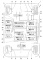
- FIG. 1 is a system configuration diagram showing a conceptual configuration of an electric vehicle equipped with a vehicle attitude control device according to a first embodiment of the present invention.
- FIG. 2 is a control block diagram of the vehicle attitude control device of FIG. 1. It is a flowchart which shows the limit yaw rate calculation of the vehicle attitude
- FIG. 1 is a block diagram of a conceptual configuration of an electric vehicle, and the upper side of the figure is the front of the vehicle.
- the electric vehicle includes a vehicle control device 10.
- This vehicle control device 10 is equipped with a vehicle attitude control device 24 according to this embodiment.
- This electric vehicle is a left-right wheel independent drive type vehicle.
- this electric vehicle is a four-wheel independent drive in which a pair of left and right rear wheels 2 and 2 and a pair of left and right front wheels 3 and 3 of a vehicle 1 are independently driven by an electric motor 4 as a power source. It is a car.
- the front wheels 3 and 3 are steering wheels.
- Each motor 4 constitutes, for example, the in-wheel motor drive device 5 of FIG. 5, but may be an on-board type mounted on a chassis (not shown).
- the in-wheel motor drive device 5 includes a motor 4 that is an in-wheel motor (IWM), a speed reducer 6, and a wheel bearing 7, and a part or all of these are arranged in the wheel 2. .
- the rotation of the motor 4 is transmitted to the wheel 2 (3) via the speed reducer 6 and the wheel bearing 7.
- a brake rotor 8a constituting the friction brake device 8 is fixed to the flange portion of the hub wheel 7a of the wheel bearing 7, and the brake rotor 8a rotates integrally with the wheel 2 (3).
- the motor 4 is, for example, an embedded magnet type synchronous motor in which a permanent magnet is built in the core portion of the rotor 4a.
- the motor 4 is a motor in which a radial gap is provided between a stator 4b fixed to the housing 4c and a rotor 4a attached to the rotation output shaft 9.
- the vehicle control device 10 includes a plurality of ECUs 11 mounted on the vehicle 1, a pair of motors 4, 4 for the front wheels 3, 3 and a pair of motors 4, 4 for the rear wheels 2, 2 ( In this example, two inverter devices 12 are provided.
- the ECU 11 includes, as its basic configuration, an integrated control unit 23, a driving force command unit 21, and a braking / driving force distribution unit 22.
- the integrated control unit 23 is a control unit that performs overall control and cooperative control of the entire vehicle.
- the driving force command means 21 is based on the detection signal for the operation amount of the accelerator operation means such as the accelerator pedal 14 and the detection signal for the operation amount of the brake operation means such as the brake pedal 15.
- the braking / driving force distribution means 22 distributes the command output from the driving force command means 21 as an individual braking / driving force command, for example, a torque command, to the inverter device 12 of each motor 4 according to the setting rule.
- Each inverter device 12 is means for converting DC power of a battery (not shown) into AC power for driving the motor 4, and has a control unit (not shown) for controlling the output thereof.
- the corresponding motor 4 is controlled in accordance with a braking / driving force command such as the distributed torque command.
- one inverter device 12 is provided for each of the two front and rear motors 4.
- each front and rear inverter device 12 has the left and right motors 4 individually in one inverter device 12. It has the structure controlled to.
- each inverter device 12 is provided with a power circuit section (not shown) such as a gate circuit of a switching element that converts AC power for each of the pair of left and right motors 4 and 4, and the control section is time-shared.
- two power circuit units are controlled by one unit. Instead of providing two inverter devices 12 as described above, a total of four inverter devices 12 may be provided for each motor 4.
- the ECU 11 includes a computer such as a microcomputer, a program executed on the computer, and various electronic circuits.
- the ECU 11 and each inverter device 12 are connected by an in-vehicle communication network such as a CAN (control area network).
- the ECU 11 having the above basic configuration further includes a vehicle attitude control device 24.
- the vehicle 1 is provided with vehicle speed detection means 16, lateral acceleration sensor 17, steering angle sensor 18, and yaw rate sensor 19 as sensors.
- the steering angle sensor 18 is a sensor that detects a steering angle of the steering means 13 such as a steering handle, or a sensor that detects a steering angle from a steering device (not shown).
- the vehicle attitude control device 24 obtains a standard yaw rate from various vehicle state quantities such as a vehicle speed and a steering angle, calculates a target yaw moment based on a deviation between the standard yaw rate and the actual yaw rate, and the target yaw moment
- the braking / driving force necessary for realizing the above is added to the braking / driving force distributed to the power source of each wheel.
- a road surface friction coefficient is estimated from the actual lateral acceleration and the lateral acceleration change rate, and a limit yaw rate is determined based on the estimated road surface friction coefficient.
- the reference yaw rate calculated based on the vehicle speed and the steering angle is corrected with the determined limit yaw rate. This improves the responsiveness of the vehicle at the initial stage of steering, while improving the limit performance and preventing excessive skidding in the limit region, thereby stabilizing the vehicle posture.
- the vehicle attitude control device 24 includes provisional standard yaw rate calculation means 25, target yaw moment calculation means 26, yaw moment control means 27, limit yaw rate calculation means 28, and standard yaw rate correction means 29.
- the vehicle attitude control device 24 is embodied by a program comprising an algorithm to be described later of each of these means 25 to 29.
- the processor of the ECU 21 is programmed to execute the algorithms of the means 25 to 29.
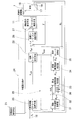
- FIG. 2 is a control block diagram of the vehicle attitude control device 24.
- the provisional standard yaw rate calculation means 25 is a means for obtaining a standard yaw rate from the vehicle speed and the steering angle.
- the vehicle speed is obtained from the vehicle speed detection means 16, and the steering angle is obtained from the steering angle sensor 18.
- the target yaw moment calculating means 26 calculates a target yaw moment based on the deviation between the standard yaw rate and the actual yaw rate detected by the yaw rate sensor 19.
- the yaw moment control means 27 applies the braking / driving force necessary for realizing the target yaw moment to the braking / driving force distributed to the motor 4 of each wheel given from the braking / driving force command means 21.
- the yaw moment control means 27 may be configured as a part of the braking / driving force control means 11 or may be provided separately from the braking / driving force control means 11.
- the limit yaw rate calculating means 28 estimates the road surface friction coefficient and determines the limit yaw rate based on the estimated road surface friction coefficient.
- the reference yaw rate correcting means 29 corrects the reference yaw rate using the limit yaw rate when the reference yaw rate is larger than the limit yaw rate determined by the limit yaw rate calculating means 28.
- the limit yaw rate calculation means 28 includes a reference lateral acceleration calculation unit 31, an addition unit 32, a differentiation unit 36, a road surface friction coefficient estimator 33, a road surface friction coefficient corrector 34, and a limit yaw rate calculation unit 35.
- the limit yaw rate calculation means 28 which will be described in detail later, is calculated by dividing the product of the estimated road friction coefficient by a constant and a gravitational acceleration as the limit lateral acceleration and dividing the limit lateral acceleration by the vehicle speed. The obtained value is defined as the limit yaw rate.
- the limit yaw rate calculating means 28 obtains the standard lateral acceleration from the vehicle speed and the steering angle, compares the standard lateral acceleration and the actual lateral acceleration, and the lateral acceleration deviation which is the deviation between them is larger than the deviation threshold value and If the acceleration change rate is less than the change rate threshold, the value obtained by dividing the lateral acceleration by the gravitational acceleration is taken as the estimated road friction coefficient, and the lateral acceleration deviation is less than the deviation threshold, or the change rate of the actual lateral acceleration changes. When it is larger than the rate threshold, a predetermined value is set as the estimated road surface friction coefficient. In the case of this configuration, the limit yaw rate calculating means 28 may correct the estimated road surface friction coefficient so as to be smaller than the road surface friction coefficient while the road surface friction coefficient is increasing. .
- FIG. 3 is a flowchart of the standard yaw rate calculation.
- the normative lateral acceleration calculator 31 of the limit yaw rate calculator 28 calculates the normative lateral acceleration ⁇ y ref (step S1).
- G ⁇ r (0) is a yaw rate gain constant
- ⁇ n is a natural frequency of the vehicle
- ⁇ is a damping ratio
- T r is a constant
- s is a Laplace operator.
- the natural frequency ⁇ n and the damping ratio ⁇ of the vehicle depend on the vehicle speed V.
- the adder 32 calculates a deviation ⁇ y between the reference lateral acceleration ⁇ y ref and the actual lateral acceleration ⁇ y detected by the lateral acceleration sensor 17 (step S2a).
- the road surface friction coefficient estimator 33 determines the actual lateral acceleration when the magnitude of the lateral acceleration deviation
- ⁇ y is divided by the gravitational acceleration g to obtain a road surface friction coefficient estimated value ⁇ es (step S3).
- the specified value ⁇ H of the road surface friction coefficient is a predetermined value and is a road surface friction coefficient on a high ⁇ road.
- the specified value mu H is different by the vehicle.
- the road surface friction coefficient corrector 34 determines a road surface friction coefficient correction value ⁇ ev from the estimated road surface friction coefficient estimated value ⁇ es . Specifically, the road surface friction coefficient correction value ⁇ ev is decreased by the road surface friction coefficient corrector 34 following the road surface friction coefficient estimated value ⁇ es when the road surface friction coefficient estimated value ⁇ es decreases. When the road surface friction coefficient estimated value ⁇ es increases, the road surface friction coefficient estimated value ⁇ es is gradually increased (that is, delayed from the road surface friction coefficient estimated value ⁇ es ) (step S5).
- the road surface friction coefficient correction value mu ev is smaller than the road surface friction coefficient estimated value ⁇ es .
- the road surface friction coefficient correction value ⁇ ev is quickly reduced to reduce the standard yaw rate and prevent the vehicle from becoming unstable, while the steering is small and the horizontal
- the road surface friction coefficient correction value ⁇ ev is gradually increased to rapidly increase the reference yaw rate ⁇ ref or the vehicle attitude. Changes can be prevented.
- the limit yaw rate calculation unit 35 adds a constant to the road surface friction coefficient correction value ⁇ ev (step S6), and sets the product with the gravitational acceleration g as the limit lateral acceleration G ylimit (step S7).
- a limit yaw rate ⁇ limit is determined from the limit lateral acceleration G ylimit by the following equation (step S8).
- ⁇ limit G ylimit / V
- the limit yaw rate is calculated based on the lateral acceleration slightly larger than the actual lateral acceleration, so the side slip angle of the vehicle 1 slightly increases and effectively understeers. Can be reduced.
- the road surface friction coefficient is set as a road surface friction coefficient correction value ⁇ ev .
- the reference yaw rate correction unit 29 corrects the provisional reference yaw rate by limiting the magnitude of the limit yaw rate (step S9). That is,
- the target yaw moment calculating means 26 calculates the target yaw moment based on the corrected standard yaw rate ⁇ ref and the deviation ⁇ between the actual yaw rate ⁇ detected by the yaw rate sensor 19.
- the vehicle speed V the the information of the vehicle behavior, such as lateral acceleration alpha y, determines oversteer or understeer condition.
- FIG. 4A shows an example of the braking / driving force applied to each wheel 2 during the right turn understeer in the case of the four-wheel drive vehicle shown in FIG.
- a driving force is applied to the rear wheel outside the turn as shown in FIG. 4B.
- the reference yaw rate ⁇ ref at the initial stage of the steering is calculated with the yaw rate that can be generated on the high ⁇ road, the response is further improved. Furthermore, the understeer tendency is reduced and the turning limit is improved. In the limit region, the normative yaw rate ⁇ ref is calculated in consideration of the road surface friction coefficient estimated value ⁇ es, and the value is limited by the maximum yaw rate that can be generated on the current road surface. The behavior of the vehicle is less likely to become unstable.
Abstract
操舵初期の車両の応答性を向上させる一方、限界性能の向上と限界領域での過大な横滑りを防止し車両姿勢を安定化する車両姿勢制御装置を提供する。車両姿勢制御装置(24)は、少なくとも左右一対の車輪(2 (3))の制駆動トルクを独立に制御可能な車両(1)を制御する車両制御装置(10)に設けられる。車両姿勢制御装置(10)は、車速と操舵角から規範ヨーレートを求める暫定規範ヨーレート演算手段(25)と、規範ヨーレートと実ヨーレートとの偏差に基づいて目標ヨーモーメントを算出する目標ヨーモーメント演算手段(26)と、目標ヨーモーメントを実現するために必要な制駆動力を、制駆動力指令手段(21)から与えられる各輪の制駆動力に加えるヨーモーメント制御手段(27)と、路面摩擦係数を推定して限界ヨーレートを定める限界ヨーレート演算手段(28)と、規範ヨーレートが限界ヨーレートより大きい場合に、限界ヨーレートを用いて規範ヨーレートを修正する規範ヨーレート修正手段(29)と備える。
Description
本出願は、2015年1月28日出願の特願2015-013904の優先権を主張するものであり、それらの全体を参照により本願の一部をなすものとして引用する。
この発明は、旋回性能の向上と、旋回限界領域での車両挙動の安定化とを図る車両姿勢制御装置に関する。
従来、車両姿勢制御装置において、車速や操舵角等の各種車両状態量から規範ヨーレートを求め、規範ヨーレートと実ヨーレートとの偏差に基づいて目標ヨーモーメントを算出し、その目標ヨーモーメントを実現するために必要な制駆動力を各輪に加えることにより、安定した車両挙動を確保するものが知られている(例えば、特許文献1)。
しかし、車両の運動目標となる状態量をヨーレートのみとした場合、タイヤのコーナリングパワーが非線形特性となる限界領域では、規範ヨーレートを実現すると車両横滑り角も増大し、車両の挙動が不安定となる場合がある。そのため、ヨーレートフィードバックによって制御する一方、車両の横滑り角フィードバックによっても制御し、これらを所定の条件に応じて切り換えることで、このような状態での車両の挙動を安定させるものが公知である(特許文献2)。
特許文献3では、特許文献2の横滑り角フィードバックによる制御を付加する対策の代わりに、車体横滑り角に応じヨーイング運動目標値を修正することで、従来のヨーイング挙動制御で生じていた車両挙動が益々不安定になるという問題を解消する方法が提案されている。
特許文献3や特許文献4では、実横加速度を車速で除して求めたヨーレートの値を上限として、車速や操舵角等の各種車両状態量から求めた規範ヨーレートを修正することによっても、横滑り角の過大な増加を抑制している。しかし、この方法を用いると、操舵初期の車両運動の応答性向上は望めない。
また、横滑り防止制御装置では、路面の摩擦係数を随時推測しながら制御を行うものがあり、例えば特許文献4では,横加速度評価値が第1の閾値以上であるという第1の条件を満たす場合、または、前記横加速度評価値が前記第1の閾値よりも小さな第2の閾値以上であるとともに前記横加速度評価値の時間的変化率が所定値以上であるという第2の条件を満たす場合に、前記車両が走行している路面が高μ路であると判定し、第1の条件および第2の条件のいずれをも満たさない場合に、前記路面が低μ路であると判定する方法が示されている。
特許文献2の方法では、制御の切り替え時にドライバに違和感を与える恐れがあり、また実横滑り角の値が必要である。特許文献3の方法でも、やはり実横滑り角の値が必要である。横滑り角を実測するためのセンサを搭載すると非常にコストがかかり、あらゆる状況において精度良く推定することは困難である。また、特許文献3や特許文献4では、実横加速度を車速で除して求めたヨーレートの値を上限として、車速や操舵角等の各種車両状態量から求めた規範ヨーレートを修正することによっても、横滑り角の過大な増加を抑制しているが、この方法では操舵初期の車両運動の応答性向上は望めない。
特許文献4では、直進走行状態のような横加速度が小さい場合は高μ路でも低μ路と判断してしまう。
特許文献4では、直進走行状態のような横加速度が小さい場合は高μ路でも低μ路と判断してしまう。
この発明は、上記課題を解消するものであり、操舵初期の車両の応答性を向上させる一方、限界性能の向上と限界領域での過大な横滑りを防止し車両姿勢を安定化する車両姿勢制御装置を提供することを目的とする。
以下、便宜上理解を容易にするために、実施形態の符号を参照して説明する。
この発明の一構成に係る、車両姿勢制御装置は、少なくとも左右一対の車輪2(3)の各車輪に対してそれぞれ設けられた少なくとも2つの動力源4を備えた車両を制御する車両制御装置10であって、前記少なくとも2つの動力源4を個別に制御することで前記各車輪2(3)の制駆動トルクを独立に制御する車両制御装置10に設けられた車両姿勢制御装置24であって、
車速と操舵角から規範ヨーレートを求める暫定規範ヨーレート演算手段25と、
前記規範ヨーレートとヨーレートセンサ19によって検出された実ヨーレートとの偏差に基づいて目標ヨーモーメントを算出する目標ヨーモーメント演算手段26と、
前記目標ヨーモーメントを実現するために必要な制駆動力を、制駆動力指令手段21から与えられて各輪の動力源4に配分する制駆動力に加えるヨーモーメント制御手段27と、
路面摩擦係数を推定し、推定されたこの路面摩擦係数に基づき限界ヨーレートを定める限界ヨーレート演算手段28と、
前記規範ヨーレートが前記限界ヨーレート演算手段28で定められた限界ヨーレートより大きい場合に、前記限界ヨーレートを用いて規範ヨーレートを修正する規範ヨーレート修正手段29とを備える。
この構成によると、車速と操舵角から規範ヨーレートを求め、規範ヨーレートと実ヨーレートとの偏差に基づいて目標ヨーモーメントを算出し、その目標ヨーモーメントを実現するために必要な制動力または駆動力を各輪に加えるため、操舵初期の応答性が向上する。
その一方、路面摩擦係数を推定し、推定された路面摩擦係数に基づき限界ヨーレートを定め、前記規範ヨーレートが限界ヨーレートよりも大きい場合は限界ヨーレートを用いて規範ヨーレートを修正するため、タイヤのコーナリングパワーが非線形特性となる限界領域では、規範ヨーレートは推定された路面摩擦係数を考慮して計算される。これにより、現在の路面において発生し得る最大ヨーレートによって目標ヨーモーメントが制限されることになる。そのため、過大な横滑り角が生じることがなく、車両の挙動が不安定となる恐れがない。これにより、限界性能の向上と限界領域での過大な横滑りの防止との効果を得ることができる。
前記限界ヨーレート演算手段28は、推定された前記路面摩擦係数に定数を加算した値と重力加速度との積を限界横加速度とし、この限界横加速度を車速で除して算出された値を前記限界ヨーレートとして出力するようにしても良い。
このように、推定された前記路面摩擦係数に定数を加算した値を用いて限界横加速度を求め、この限界横加速度を車速で除して限界ヨーレートとするため、実横加速度よりも僅かに大きな横加速度に基づいて限界ヨーレートが計算されるようにできる。したがって、車両の横滑り角が僅かに増加し、効果的にアンダーステアを低減することができる。
前記限界ヨーレート演算手段28は、車速と操舵角から規範横加速度を求め、規範横加速度と実横加速度の偏差である横加速度偏差が偏差閾値よりも大きく、かつ実横加速度の変化率が変化率閾値以下の場合は、実横加速度を重力加速度で除した値を、推定された前記路面摩擦係数とし、前記横加速度偏差が偏差閾値以下、または実横加速度の変化率が変化率閾値よりも大きい場合は、予め定められた値を、推定された前記路面摩擦係数としても良い。
このように、実横加速度と規範横加速度の偏差と、実横加速度の変化率とを参照することによって、タイヤの限界(横滑り角に対するコーナリングフォースの飽和)を精度良く検出することができる。そのため、より一層の限界性能の向上と限界領域での過大な横滑りの防止との効果を高めることができる。
好ましい実施形態において、前記限界ヨーレート演算手段28は、推定された前記路面摩擦係数を、推定された前記路面摩擦係数が増加している間は、この路面摩擦係数よりも小さくなるように補正しても良い。
推定された路面摩擦係数を、その増加時にはその推定された路面摩擦係数よりも小さくなるように補正することで、路面のμ値が増加しても、限界ヨーレートの増大を抑制し、限界領域での過大な横滑りの防止をより確実に行うことができる。
推定された路面摩擦係数を、その増加時にはその推定された路面摩擦係数よりも小さくなるように補正することで、路面のμ値が増加しても、限界ヨーレートの増大を抑制し、限界領域での過大な横滑りの防止をより確実に行うことができる。
別の好ましい実施形態において、前記予め定められた値は、高μ路における路面摩擦係数であっても良い。
この発明の他の構成に係る、車両姿勢制御装置は、車両を制御する車両制御装置10であって、前記車両1が、少なくとも左右一対の車輪2(3)の各車輪に対してそれぞれ設けられた少なくとも2つの動力源4を有し、
当該車両制御装置10が、
前記少なくとも2つの動力源4を個別にトルク制御する少なくとも1つのインバータ装置12と、
前記少なくともインバータ装置12に接続されたプロセッサ11であって、
各輪2(3)の動力源4に配分する指令制駆動力を決定し、
車速と操舵角から規範ヨーレートを求め、
前記規範ヨーレートとヨーレートセンサによって検出された実ヨーレートとの偏差に基づいて目標ヨーモーメントを算出し、
前記目標ヨーモーメントを実現するために必要な制駆動力を、前記指令制動力に加え、
路面摩擦係数を推定し、推定されたこの路面摩擦係数に基づき限界ヨーレートを定め、
前記規範ヨーレートが定められた前記限界ヨーレートより大きい場合に、前記限界ヨーレートを用いて規範ヨーレートを修正するようにプログラムされたプロセッサ11とを備える。
請求の範囲および/または明細書および/または図面に開示された少なくとも2つの構成のどのような組合せも、本発明に含まれる。特に、請求の範囲の各請求項の2つ以上のどのような組合せも、本発明に含まれる。
この発明は、添付の図面を参考にした以下の好適な実施形態の説明から、より明瞭に理解されるであろう。しかしながら、実施形態および図面は単なる図示および説明のためのものであり、この発明の範囲を定めるために利用されるべきものではない。この発明の範囲は添付の請求の範囲によって定まる。添付図面において、複数の図面における同一の符号は、同一または相当する部分を示す。
この発明の第1の実施形態に係る車両姿勢制御装置を搭載した電気自動車の概念構成を示すシステム構成図である。
図1の車両姿勢制御装置の制御ブロック図である。
図1の同車両姿勢制御装置の限界ヨーレート演算を示すフローチャートである。
図1の車両姿勢制御装置を適用した4輪駆動車における姿勢制御時の各駆動力を示す説明図である。
図1の車両姿勢制御装置を適用した後輪駆動車における姿勢制御時の各駆動力を示す説明図である。
図1の電気自動車におけるモータが構成するモータ駆動装置の一例であるインホイールモータ駆動装置の概略断面図である。
この発明の第1の実施形態を図1ないし図5と共に説明する。図1は、電気自動車の概念構成のブロック図であり、図の上側が車両の前方である。この電気自動車は車両制御装置10を備える。この車両制御装置10が、本実施形態に係る車両姿勢制御装置24を搭載する。この電気自動車は、左右輪独立駆動式車両である。つまり、この電気自動車は、車両1の左右一対の後輪2,2および左右一対の前輪3,3が、いずれも動力源である電動のモータ4で独立して駆動される4輪独立駆動の自動車である。前輪3,3は操舵輪である。各モータ4は、例えば図5のインホイールモータ駆動装置5を構成するが、車台(図示せず)上に搭載されるオンボード形式であっても良い。
図5において、インホイールモータ駆動装置5は、インホイールモータ(IWM)であるモータ4、減速機6、および車輪用軸受7を有し、これらの一部または全体が車輪2内に配置される。モータ4の回転は、減速機6および車輪用軸受7を介して車輪2(3)に伝達される。車輪用軸受7のハブ輪7aのフランジ部には摩擦ブレーキ装置8を構成するブレーキロータ8aが固定され、同ブレーキロータ8aは車輪2(3)と一体に回転する。モータ4は、例えば、ロータ4aのコア部に永久磁石が内蔵された埋込磁石型同期モータである。このモータ4は、ハウジング4cに固定したステータ4bと、回転出力軸9に取り付けたロータ4aとの間にラジアルギャップを設けたモータである。
図1を参照して、制御系を説明する。車両制御装置10は、車両1に搭載されたECU11と、前輪3,3用の一対のモータ4,4および後輪2,2用の一対のモータ4,4に対してそれぞれ設けられた複数(この例では2つ)のインバータ装置12とを有する。ECU11は、その基本的な構成として、統合制御手段23と、駆動力指令手段21と、制駆動力分配手段22とを有する。統合制御手段23は、自動車全般の統括制御や協調制御を行う制御手段である。駆動力指令手段21は、アクセルペダル14等のアクセル操作手段の操作量の検出信号と、ブレーキペダル15等のブレーキ操作手段の操作量の検出信号とに基づいて、車両全体の制駆動力(制動力および駆動力)の指令、例えばトルク指令を生成する手段である。制駆動力分配手段22は、駆動力指令手段21の出力する指令を、設定規則に従って各モータ4のインバータ装置12へ個別の制駆動力指令、例えばトルク指令として分配する。
各インバータ装置12は、バッテリ(図示せず)の直流電力をモータ4の駆動のための交流電力に変換する手段であって、その出力を制御する制御部(図示せず)を有し、上記の分配されたトルク指令等の制駆動力の指令に従って対応するモータ4を制御する。インバータ装置12は、図示の例では、前後それぞれ2台のモータ4に対して一台ずつ設けているが、前後の各インバータ装置12は、一台のインバータ装置12内に左右のモータ4を個別に制御する構成を有している。例えば、各インバータ装置12は、交流電力に変換するスイッチング素子のゲート回路等のパワー回路部(図示せず)が左右一対のモータ4,4に対してそれぞれ別に設けられ、その制御部は時分割等により1台で2つのパワー回路部を制御する構成とされる。前記インバータ装置12は、上記のように2台設ける代わりに、各モータ4に個別として合計4台設けても良い。
ECU11は、マイクロコンピュータ等のコンピュータとこれに実行されるプログラム、並びに各種の電子回路等で構成される。ECU11と各インバータ装置12とは、CAN(コントロール・エリア・ネットワーク)等の車内通信網で接続されている。上記の基本的な構成を有するECU11は、さらに車両姿勢制御装置24を有する。また、車両1には、センサ類として、車速検出手段16、横加速度センサ17、操舵角センサ18、およびヨーレートセンサ19が設けられている。操舵角センサ18は、ステアリングハンドル等の操舵手段13の操舵角を検出するセンサ、または転舵装置(図示せず)から操舵角を検出するセンサである。
車両姿勢制御装置24は、概要を説明すると、車速や操舵角等の各種車両状態量から規範ヨーレートを求め、規範ヨーレートと実ヨーレートとの偏差に基づいて目標ヨーモーメントを算出し、その目標ヨーモーメントを実現するために必要な制駆動力を、各輪の動力源に配分する制駆動力に加える。この際に、実横加速度および横加速度変化率から路面摩擦係数を推定し、推定された路面摩擦係数に基づき限界ヨーレートを定める。そして、車速と操舵角に基づいて演算される規範ヨーレートを、前記定めた限界ヨーレートで修正する。これにより、操舵初期の車両の応答性を向上させる一方、限界性能の向上と限界領域での過大な横滑りを防止し車両姿勢を安定化する。
車両姿勢制御装置24は、暫定規範ヨーレート演算手段25、目標ヨーモーメント演算手段26、ヨーモーメント制御手段27、限界ヨーレート演算手段28、および規範ヨーレート修正手段29を有する。車両姿勢制御装置24は、これら各手段25~29の後述するアルゴリズムからなるプログラムで具現化される。そして、ECU21のプロセッサは、手段25~29のアルゴリズムを実行するようにプログラミングされている。
図2は、車両姿勢制御装置24の制御ブロック図である。暫定規範ヨーレート演算手段25は、車速と操舵角から規範ヨーレートを求める手段である。ここで、車速は車速検出手段16から、操舵角は操舵角センサ18から取得する。目標ヨーモーメント演算手段26は、前記規範ヨーレートとヨーレートセンサ19によって検出された実ヨーレートとの偏差に基づいて目標ヨーモーメントを算出する。ヨーモーメント制御手段27は、前記目標ヨーモーメントを実現するために必要な制駆動力を、制駆動力指令手段21から与えられた各輪のモータ4に配分する制駆動力に対して加える。ヨーモーメント制御手段27は、前記制駆動力制御手段11の一部として構成されていても、また制駆動力制御手段11とは別に設けられていても良い。
限界ヨーレート演算手段28は、路面摩擦係数を推定し、推定された路面摩擦係数に基づき限界ヨーレートを定める。
規範ヨーレート修正手段29は、前記規範ヨーレートが前記限界ヨーレート演算手段28で定められた限界ヨーレートより大きい場合に、前記限界ヨーレートを用いて規範ヨーレートを修正する。
規範ヨーレート修正手段29は、前記規範ヨーレートが前記限界ヨーレート演算手段28で定められた限界ヨーレートより大きい場合に、前記限界ヨーレートを用いて規範ヨーレートを修正する。
限界ヨーレート演算手段28は、規範横加速度演算部31、加算部32、微分部36、路面摩擦係数推定器33、路面摩擦係数補正器34、および限界ヨーレート演算部35を有する。
前記限界ヨーレート演算手段28は、後により詳しく説明するが、推定された路面摩擦係数に定数を加算した値と重力加速度との積を限界横加速度とし、この限界横加速度を車速で除して算出された値を限界ヨーレートとする。
また、前記限界ヨーレート演算手段28は、車速と操舵角から規範横加速度を求め、規範横加速度と実横加速度を比較し、両者の偏差である横加速度偏差が偏差閾値よりも大きく、かつ実横加速度の変化率が変化率閾値以下の場合は、横加速度を重力加速度で除した値を、推定された路面摩擦係数とし、前記横加速度偏差が偏差閾値以下、または実横加速度の変化率が変化率閾値よりも大きい場合は、予め定められた値を、推定された前記路面摩擦係数とする。
この構成の場合に、前記限界ヨーレート演算手段28は、推定された前記路面摩擦係数を、その路面摩擦係数が増加している間は、この路面摩擦係数よりも小さくなるように補正しても良い。
この構成の場合に、前記限界ヨーレート演算手段28は、推定された前記路面摩擦係数を、その路面摩擦係数が増加している間は、この路面摩擦係数よりも小さくなるように補正しても良い。
次に、この実施形態の車両姿勢制御装置24につき、その作用と、各構成手段のより具体的な機能を説明する。この車両姿勢制御装置24は、次の手順で演算を実行する。図3はその規範ヨーレート演算のフローチャートである。
(1) 暫定規範ヨーレート演算手段25は、操舵角δhと車速Vより、次式のように、車両モデルに基づき暫定規範ヨーレートγref*を求める(ステップS1)。限界ヨーレート演算手段28の規範横加速度演算部31は、規範横加速度αyrefを求める(ステップS1)。

(2) 規範横加速度αyrefと横加速度センサ17で検出した実横加速度αyとの偏差Δαyを加算部32で算出する(ステップS2a)。
路面摩擦係数推定器33は、横加速度偏差の大きさ|Δαy|が偏差閾値よりも大きく、かつ実横加速度の変化率の大きさが変化率閾値以下の場合(ステップS2b)、実横加速度αyを重力加速度gで除して路面摩擦係数推定値μesとする(ステップS3)。
μes=|αy/g|
横加速度偏差の大きさ|Δαy|が偏差閾値以下、または実横加速度の変化率の大きさが変化率閾値よりも大きい場合は、路面摩擦係数の規定値μHを路面摩擦係数推定値μesとする(ステップS4)。
μes=μH
路面摩擦係数推定器33は、横加速度偏差の大きさ|Δαy|が偏差閾値よりも大きく、かつ実横加速度の変化率の大きさが変化率閾値以下の場合(ステップS2b)、実横加速度αyを重力加速度gで除して路面摩擦係数推定値μesとする(ステップS3)。
μes=|αy/g|
横加速度偏差の大きさ|Δαy|が偏差閾値以下、または実横加速度の変化率の大きさが変化率閾値よりも大きい場合は、路面摩擦係数の規定値μHを路面摩擦係数推定値μesとする(ステップS4)。
μes=μH
路面摩擦係数の規定値μHは、予め定められた値であり、高μ路における路面摩擦係数である。この規定値μHは、車両によって異なる。
実横加速度と規範横加速度の偏差と、実横加速度の変化率とを参照することによって、タイヤの限界(横滑り角に対するコーナリングフォースの飽和)を精度良く検出することができる。
実横加速度と規範横加速度の偏差と、実横加速度の変化率とを参照することによって、タイヤの限界(横滑り角に対するコーナリングフォースの飽和)を精度良く検出することができる。
(3) 路面摩擦係数補正器34は、推定された路面摩擦係数推定値μesから路面摩擦係数補正値μevを定める。具体的には、路面摩擦係数補正値μevは、路面摩擦係数補正器34により、路面摩擦係数推定値μesが減少するときは路面摩擦係数推定値μesに追従して減少するのに対して、路面摩擦係数推定値μesが増加するときは、徐々に(つまり、路面摩擦係数推定値μesよりも遅れて)増加するようにする(ステップS5)。すなわち、路面摩擦係数推定値μesが減少している間、路面摩擦係数補正値μevは路面摩擦係数推定値μesに等しく、路面摩擦係数推定値μesが減少している間、路面摩擦係数補正値μevは路面摩擦係数推定値μesよりも小さい。
これにより、低μを検出した場合には、すみやかに路面摩擦係数補正値μevを低下させることにより規範ヨーレートを低下させて車両が不安定になるのを防止しする一方、操舵が小さく規範横加速度と実横加速度との偏差が小さい場合や高μ路に移行した場合には、徐々に路面摩擦係数補正値μevを増加させることにより、規範ヨーレートγrefの急激な増加や車両姿勢の急激な変化を防ぐことができる。
(4) 限界ヨーレート演算部35は、路面摩擦係数補正値μevに定数を加算し(ステップS6)、重力加速度gとの積を限界横加速度Gylimitとする(ステップS7)。限界横加速度Gylimitから、次式により限界ヨーレートγlimitを定める(ステップS8)。
γlimit=Gylimit/V
路面摩擦係数補正値μevに定数を加算することにより、実横加速度より僅かに大きな横加速度に基づいて限界ヨーレートが計算されるため、車両1の横滑り角が僅かに増加し、効果的にアンダーステアを低減することができる。
なお、他の方法により計測または推定された路面摩擦係数を用いる場合は、その路面摩擦係数を路面摩擦係数補正値μevとする。
γlimit=Gylimit/V
路面摩擦係数補正値μevに定数を加算することにより、実横加速度より僅かに大きな横加速度に基づいて限界ヨーレートが計算されるため、車両1の横滑り角が僅かに増加し、効果的にアンダーステアを低減することができる。
なお、他の方法により計測または推定された路面摩擦係数を用いる場合は、その路面摩擦係数を路面摩擦係数補正値μevとする。
(5) 規範ヨーレート修正手段29は、暫定規範ヨーレートγref*が限界ヨーレートγlimitより大きい場合、限界ヨーレートの大きさで制限して暫定規範ヨーレートを修正する(ステップS9)。すなわち、
|γref|≦|γlimit|
が満たされることになる。
|γref|≦|γlimit|
が満たされることになる。
(6) 目標ヨーモーメント演算手段26は、修正後の規範ヨーレートγrefとヨーレートセンサ19で検出された実ヨーレートγの偏差Δγに基づいて、目標ヨーモーメントを計算する。実ヨーレートγ、ヨーレート偏差Δγ、車速V、横加速度αy等の車両挙動の情報から、オーバーステア状態またはアンダーステア状態を判断する。例えば、規範ヨーレートの絶対値|γref|より実ヨーレートの絶対値|γ|が小さい場合は、アンダーステアと判断する。アンダーステア状態の場合は、アクセルペダル14の操作量等により制駆動力指令手段21で決定される制駆動力指令値に加えて、目標ヨーモーメントとなるように、車両旋回の内側となる前後の車輪2に制動力、車両旋回の外側となる前後の車輪2に駆動力を付加する。これにより、内向きのヨーモーメントが発生し、アンダーステア傾向を低減することができる。
図4Aに、図1の4輪駆動車の場合における右旋回アンダーステア時に、各輪2に加えられる制駆動力の例を示す。後輪駆動車の場合は、図4Bのように旋回外側の後輪に駆動力を加えることになるが、四輪駆動車の場合は旋回外側の前輪にも駆動力を加えることが可能である。
以上により、操舵初期の規範ヨーレートγrefは高μ路において発生し得るヨーレートで計算されるため、より応答性が向上する。さらに、アンダーステア傾向が低減され、旋回限界が向上する。また、限界領域では、規範ヨーレートγrefは路面摩擦係数推定値μesを考慮して計算され、現在の路面において発生し得る最大ヨーレートによって値が制限されるため、過大な横滑り角が生じることがなく、車両の挙動が不安定となりにくい。
なお、インホイールモータ方式の四輪駆動車について本実施形態を説明したが、後輪2輪のみにインホイールモータを備える後輪駆動車や、非インホイールモータ方式の車両、例えば、左右輪それぞれに対応させて車体に設置された2つのモータの出力をドライブシャフト等を介して各車輪にそれぞれ伝達し、各車輪の駆動トルクを独立して制御する構成の電気自動車においても、この発明を適用することができる。
以上のとおり、図面を参照しながら好適な実施形態を説明したが、当業者であれば、本件明細書を見て、自明な範囲内で種々の変更および修正を容易に想定するであろう。したがって、そのような変更および修正は、請求の範囲から定まる発明の範囲内またはこれと均等の範囲内のものと解釈される。
1…車両
2…車輪
4…モータ(動力源)
10…車両制御装置
24…車両姿勢制御装置
25…暫定規範ヨーレート演算手段
26…目標ヨーモーメント演算手段
27…ヨーモーメント制御手段
28…限界ヨーレート演算手段
29…規範ヨーレート修正手段
2…車輪
4…モータ(動力源)
10…車両制御装置
24…車両姿勢制御装置
25…暫定規範ヨーレート演算手段
26…目標ヨーモーメント演算手段
27…ヨーモーメント制御手段
28…限界ヨーレート演算手段
29…規範ヨーレート修正手段
Claims (6)
- 少なくとも左右一対の車輪の各車輪に対してそれぞれ設けられた少なくとも2つの動力源を備えた車両を制御 する車両制御装置であって、前記少なくとも2つの動力源を個別に制御することで前記各車輪の制駆動トルクを独立に制御する車両制御装置に設けられた車両姿勢制御装置であって、
車速と操舵角から規範ヨーレートを求める暫定規範ヨーレート演算手段と、
前記規範ヨーレートとヨーレートセンサによって検出された実ヨーレートとの偏差に基づいて目標ヨーモーメントを算出する目標ヨーモーメント演算手段と、
前記目標ヨーモーメントを実現するために必要な制駆動力を、制駆動力指令手段から与えられて各輪の動力源に配分する制駆動力に加えるヨーモーメント制御手段と、
路面摩擦係数を推定し、推定されたこの路面摩擦係数に基づき限界ヨーレートを定める限界ヨーレート演算手段と、
前記規範ヨーレートが前記限界ヨーレート演算手段で定められた限界ヨーレートより大きい場合に、前記限界ヨーレートを用いて規範ヨーレートを修正する規範ヨーレート修正手段とを備えた車両姿勢制御装置。 - 請求項1に記載の車両姿勢制御装置において、前記限界ヨーレート演算手段は、推定された前記路面摩擦係数に定数を加算した値と重力加速度との積を限界横加速度とし、この限界横加速度を車速で除して算出された値を前記限界ヨーレートとして出力する車両姿勢制御装置。
- 請求項1に記載の車両姿勢制御装置において、前記限界ヨーレート演算手段は、車速と操舵角から規範横加速度を求め、規範横加速度と実横加速度の偏差である横加速度偏差が偏差閾値よりも大きく、かつ実横加速度の変化率が変化率閾値以下の場合は、実横加速度を重力加速度で除した値を、推定された前記路面摩擦係数とし、前記横加速度偏差が偏差閾値以下、または実横加速度の変化率が変化率閾値よりも大きい場合は、予め定められた値を、推定された前記路面摩擦係数とする車両姿勢制御装置。
- 請求項3に記載の車両姿勢制御装置において、前記限界ヨーレート演算手段は、推定された前記路面摩擦係数を、推定された前記路面摩擦係数が増加している間は、この路面摩擦係数よりも小さくなるように補正する車両姿勢制御装置。
- 請求項3に記載の車両姿勢制御装置において、前記予め定められた値は、高μ路における路面摩擦係数である車両姿勢制御装置。
- 車両を制御する車両制御装置であって、前記車両が、少なくとも左右一対の車輪の各車輪に対してそれぞれ設けられた少なくとも2つの動力源を有し、
当該車両制御装置が、
前記少なくとも2つの動力源を個別にトルク制御する少なくとも1つのインバータ装置と、
前記少なくとも1つのインバータ装置に接続されたプロセッサであって、
各輪の動力源に配分する指令制駆動力を決定し、
車速と操舵角から規範ヨーレートを求め、
前記規範ヨーレートとヨーレートセンサによって検出された実ヨーレートとの偏差に基づいて目標ヨーモーメントを算出し、
前記目標ヨーモーメントを実現するために必要な制駆動力を、前記指令制動力に加え、
路面摩擦係数を推定し、推定されたこの路面摩擦係数に基づき限界ヨーレートを定め、
前記規範ヨーレートが定められた前記限界ヨーレートより大きい場合に、前記限界ヨーレートを用いて規範ヨーレートを修正するようにプログラムされたプロセッサとを備えた車両姿勢制御装置。
Applications Claiming Priority (2)
| Application Number | Priority Date | Filing Date | Title |
|---|---|---|---|
| JP2015-013904 | 2015-01-28 | ||
| JP2015013904A JP6584779B2 (ja) | 2015-01-28 | 2015-01-28 | 車両姿勢制御装置 |
Publications (1)
| Publication Number | Publication Date |
|---|---|
| WO2016121546A1 true WO2016121546A1 (ja) | 2016-08-04 |
Family
ID=56543164
Family Applications (1)
| Application Number | Title | Priority Date | Filing Date |
|---|---|---|---|
| PCT/JP2016/051229 WO2016121546A1 (ja) | 2015-01-28 | 2016-01-18 | 車両姿勢制御装置 |
Country Status (2)
| Country | Link |
|---|---|
| JP (1) | JP6584779B2 (ja) |
| WO (1) | WO2016121546A1 (ja) |
Cited By (5)
| Publication number | Priority date | Publication date | Assignee | Title |
|---|---|---|---|---|
| GB2554531A (en) * | 2016-08-09 | 2018-04-04 | Ford Global Tech Llc | Controlling skidding vehicles |
| WO2018110346A1 (ja) * | 2016-12-13 | 2018-06-21 | 本田技研工業株式会社 | トルク配分装置の制御装置 |
| CN110329239A (zh) * | 2018-03-28 | 2019-10-15 | 马自达汽车株式会社 | 车辆的控制装置 |
| US11752989B2 (en) | 2021-06-01 | 2023-09-12 | Toyota Research Institute, Inc. | Purposeful brake-induced wheel lockup for vehicle stability control in autonomous vehicles |
| US11834026B2 (en) | 2021-06-01 | 2023-12-05 | Toyota Research Institute, Inc. | Purposeful brake-induced wheel lockup for vehicle stability control |
Families Citing this family (5)
| Publication number | Priority date | Publication date | Assignee | Title |
|---|---|---|---|---|
| JP6438449B2 (ja) * | 2016-11-18 | 2018-12-12 | 本田技研工業株式会社 | 車両制御装置 |
| CN107702727B (zh) * | 2017-09-04 | 2020-02-04 | 武汉光庭科技有限公司 | 一种自动驾驶过程中使车辆位置平滑的装置及方法 |
| JP6944125B2 (ja) * | 2017-11-17 | 2021-10-06 | トヨタ自動車株式会社 | 車両の挙動制御装置 |
| JP6607532B2 (ja) * | 2017-12-27 | 2019-11-20 | マツダ株式会社 | 車両の挙動制御装置 |
| JP6525408B1 (ja) * | 2017-12-27 | 2019-06-05 | マツダ株式会社 | 車両の挙動制御装置 |
Citations (7)
| Publication number | Priority date | Publication date | Assignee | Title |
|---|---|---|---|---|
| JPH0986378A (ja) * | 1995-09-28 | 1997-03-31 | Mitsubishi Motors Corp | 車両の旋回挙動制御装置 |
| GB2435102A (en) * | 2006-02-11 | 2007-08-15 | Ford Global Tech Llc | Friction estimation for vehicle control systems |
| JP2007276564A (ja) * | 2006-04-04 | 2007-10-25 | Honda Motor Co Ltd | 車両制御装置 |
| JP2008273289A (ja) * | 2007-04-26 | 2008-11-13 | Denso Corp | ハイブリッド車の制御装置 |
| JP2010188918A (ja) * | 2009-02-19 | 2010-09-02 | Toyota Motor Corp | 挙動制御装置 |
| US20110251749A1 (en) * | 2010-04-09 | 2011-10-13 | Chris Schwarz | Method and system for vehicle ESC system using map data |
| JP5078484B2 (ja) * | 2007-07-26 | 2012-11-21 | 日信工業株式会社 | 車両用ブレーキ液圧制御装置 |
Family Cites Families (1)
| Publication number | Priority date | Publication date | Assignee | Title |
|---|---|---|---|---|
| JP3401987B2 (ja) * | 1995-04-05 | 2003-04-28 | トヨタ自動車株式会社 | 車輌の挙動制御装置 |
-
2015
- 2015-01-28 JP JP2015013904A patent/JP6584779B2/ja active Active
-
2016
- 2016-01-18 WO PCT/JP2016/051229 patent/WO2016121546A1/ja active Application Filing
Patent Citations (7)
| Publication number | Priority date | Publication date | Assignee | Title |
|---|---|---|---|---|
| JPH0986378A (ja) * | 1995-09-28 | 1997-03-31 | Mitsubishi Motors Corp | 車両の旋回挙動制御装置 |
| GB2435102A (en) * | 2006-02-11 | 2007-08-15 | Ford Global Tech Llc | Friction estimation for vehicle control systems |
| JP2007276564A (ja) * | 2006-04-04 | 2007-10-25 | Honda Motor Co Ltd | 車両制御装置 |
| JP2008273289A (ja) * | 2007-04-26 | 2008-11-13 | Denso Corp | ハイブリッド車の制御装置 |
| JP5078484B2 (ja) * | 2007-07-26 | 2012-11-21 | 日信工業株式会社 | 車両用ブレーキ液圧制御装置 |
| JP2010188918A (ja) * | 2009-02-19 | 2010-09-02 | Toyota Motor Corp | 挙動制御装置 |
| US20110251749A1 (en) * | 2010-04-09 | 2011-10-13 | Chris Schwarz | Method and system for vehicle ESC system using map data |
Cited By (8)
| Publication number | Priority date | Publication date | Assignee | Title |
|---|---|---|---|---|
| GB2554531A (en) * | 2016-08-09 | 2018-04-04 | Ford Global Tech Llc | Controlling skidding vehicles |
| WO2018110346A1 (ja) * | 2016-12-13 | 2018-06-21 | 本田技研工業株式会社 | トルク配分装置の制御装置 |
| JPWO2018110346A1 (ja) * | 2016-12-13 | 2019-10-24 | 本田技研工業株式会社 | トルク配分装置の制御装置 |
| US10744875B2 (en) | 2016-12-13 | 2020-08-18 | Honda Motor Co., Ltd. | Control device for torque distributor |
| CN110329239A (zh) * | 2018-03-28 | 2019-10-15 | 马自达汽车株式会社 | 车辆的控制装置 |
| CN110329239B (zh) * | 2018-03-28 | 2022-07-19 | 马自达汽车株式会社 | 车辆的控制装置 |
| US11752989B2 (en) | 2021-06-01 | 2023-09-12 | Toyota Research Institute, Inc. | Purposeful brake-induced wheel lockup for vehicle stability control in autonomous vehicles |
| US11834026B2 (en) | 2021-06-01 | 2023-12-05 | Toyota Research Institute, Inc. | Purposeful brake-induced wheel lockup for vehicle stability control |
Also Published As
| Publication number | Publication date |
|---|---|
| JP2016137820A (ja) | 2016-08-04 |
| JP6584779B2 (ja) | 2019-10-02 |
Similar Documents
| Publication | Publication Date | Title |
|---|---|---|
| WO2016121546A1 (ja) | 車両姿勢制御装置 | |
| US10857995B2 (en) | Vehicle attitude control device | |
| US10780878B2 (en) | Vehicle turning control device | |
| US10093308B2 (en) | Electronic stability control system for vehicle | |
| CN109070877B (zh) | 车辆的转弯控制装置 | |
| CN108430847B (zh) | 车辆的转弯控制装置 | |
| CN107848526B (zh) | 车辆转弯控制装置 | |
| US10654470B2 (en) | Vehicle control apparatus and method for controlling vehicle | |
| US10272943B2 (en) | Control unit for vehicle and control method for vehicle | |
| JP6542017B2 (ja) | 車両姿勢制御装置 | |
| CN107848527B (zh) | 车辆转弯控制装置 | |
| CN109383617B (zh) | 电动助力转向设备及其控制方法 | |
| WO2019059131A1 (ja) | 車両制御装置 | |
| JP6585446B2 (ja) | 車両の制駆動力制御装置 | |
| JP4844148B2 (ja) | 4輪独立駆動車の駆動力配分装置 | |
| JP4918787B2 (ja) | 4輪独立駆動車の駆動力配分装置 |
Legal Events
| Date | Code | Title | Description |
|---|---|---|---|
| 121 | Ep: the epo has been informed by wipo that ep was designated in this application |
Ref document number: 16743150 Country of ref document: EP Kind code of ref document: A1 |
|
| NENP | Non-entry into the national phase |
Ref country code: DE |
|
| 122 | Ep: pct application non-entry in european phase |
Ref document number: 16743150 Country of ref document: EP Kind code of ref document: A1 |