WO2016121385A1 - 空調装置 - Google Patents
空調装置 Download PDFInfo
- Publication number
- WO2016121385A1 WO2016121385A1 PCT/JP2016/000395 JP2016000395W WO2016121385A1 WO 2016121385 A1 WO2016121385 A1 WO 2016121385A1 JP 2016000395 W JP2016000395 W JP 2016000395W WO 2016121385 A1 WO2016121385 A1 WO 2016121385A1
- Authority
- WO
- WIPO (PCT)
- Prior art keywords
- electric compressor
- refrigerant
- control
- temperature
- inverter
- Prior art date
- Legal status (The legal status is an assumption and is not a legal conclusion. Google has not performed a legal analysis and makes no representation as to the accuracy of the status listed.)
- Ceased
Links
Images


Classifications
-
- F—MECHANICAL ENGINEERING; LIGHTING; HEATING; WEAPONS; BLASTING
- F25—REFRIGERATION OR COOLING; COMBINED HEATING AND REFRIGERATION SYSTEMS; HEAT PUMP SYSTEMS; MANUFACTURE OR STORAGE OF ICE; LIQUEFACTION SOLIDIFICATION OF GASES
- F25B—REFRIGERATION MACHINES, PLANTS OR SYSTEMS; COMBINED HEATING AND REFRIGERATION SYSTEMS; HEAT PUMP SYSTEMS
- F25B31/00—Compressor arrangements
- F25B31/006—Cooling of compressor or motor
-
- B—PERFORMING OPERATIONS; TRANSPORTING
- B60—VEHICLES IN GENERAL
- B60H—ARRANGEMENTS OF HEATING, COOLING, VENTILATING OR OTHER AIR-TREATING DEVICES SPECIALLY ADAPTED FOR PASSENGER OR GOODS SPACES OF VEHICLES
- B60H1/00—Heating, cooling or ventilating devices
- B60H1/32—Cooling devices
- B60H1/3204—Cooling devices using compression
- B60H1/3205—Control means therefor
-
- B—PERFORMING OPERATIONS; TRANSPORTING
- B60—VEHICLES IN GENERAL
- B60H—ARRANGEMENTS OF HEATING, COOLING, VENTILATING OR OTHER AIR-TREATING DEVICES SPECIALLY ADAPTED FOR PASSENGER OR GOODS SPACES OF VEHICLES
- B60H1/00—Heating, cooling or ventilating devices
- B60H1/32—Cooling devices
- B60H1/3204—Cooling devices using compression
- B60H1/3225—Cooling devices using compression characterised by safety arrangements, e.g. compressor anti-seizure means or by signalling devices
-
- F—MECHANICAL ENGINEERING; LIGHTING; HEATING; WEAPONS; BLASTING
- F04—POSITIVE - DISPLACEMENT MACHINES FOR LIQUIDS; PUMPS FOR LIQUIDS OR ELASTIC FLUIDS
- F04B—POSITIVE-DISPLACEMENT MACHINES FOR LIQUIDS; PUMPS
- F04B39/00—Component parts, details, or accessories, of pumps or pumping systems specially adapted for elastic fluids, not otherwise provided for in, or of interest apart from, groups F04B25/00 - F04B37/00
- F04B39/06—Cooling; Heating; Prevention of freezing
-
- F—MECHANICAL ENGINEERING; LIGHTING; HEATING; WEAPONS; BLASTING
- F04—POSITIVE - DISPLACEMENT MACHINES FOR LIQUIDS; PUMPS FOR LIQUIDS OR ELASTIC FLUIDS
- F04D—NON-POSITIVE-DISPLACEMENT PUMPS
- F04D25/00—Pumping installations or systems
- F04D25/02—Units comprising pumps and their driving means
- F04D25/06—Units comprising pumps and their driving means the pump being electrically driven
-
- F—MECHANICAL ENGINEERING; LIGHTING; HEATING; WEAPONS; BLASTING
- F04—POSITIVE - DISPLACEMENT MACHINES FOR LIQUIDS; PUMPS FOR LIQUIDS OR ELASTIC FLUIDS
- F04D—NON-POSITIVE-DISPLACEMENT PUMPS
- F04D27/00—Control, e.g. regulation, of pumps, pumping installations or pumping systems specially adapted for elastic fluids
- F04D27/004—Control, e.g. regulation, of pumps, pumping installations or pumping systems specially adapted for elastic fluids by varying driving speed
-
- F—MECHANICAL ENGINEERING; LIGHTING; HEATING; WEAPONS; BLASTING
- F25—REFRIGERATION OR COOLING; COMBINED HEATING AND REFRIGERATION SYSTEMS; HEAT PUMP SYSTEMS; MANUFACTURE OR STORAGE OF ICE; LIQUEFACTION SOLIDIFICATION OF GASES
- F25B—REFRIGERATION MACHINES, PLANTS OR SYSTEMS; COMBINED HEATING AND REFRIGERATION SYSTEMS; HEAT PUMP SYSTEMS
- F25B49/00—Arrangement or mounting of control or safety devices
- F25B49/005—Arrangement or mounting of control or safety devices of safety devices
-
- F—MECHANICAL ENGINEERING; LIGHTING; HEATING; WEAPONS; BLASTING
- F25—REFRIGERATION OR COOLING; COMBINED HEATING AND REFRIGERATION SYSTEMS; HEAT PUMP SYSTEMS; MANUFACTURE OR STORAGE OF ICE; LIQUEFACTION SOLIDIFICATION OF GASES
- F25B—REFRIGERATION MACHINES, PLANTS OR SYSTEMS; COMBINED HEATING AND REFRIGERATION SYSTEMS; HEAT PUMP SYSTEMS
- F25B49/00—Arrangement or mounting of control or safety devices
- F25B49/02—Arrangement or mounting of control or safety devices for compression type machines, plants or systems
- F25B49/022—Compressor control arrangements
-
- F—MECHANICAL ENGINEERING; LIGHTING; HEATING; WEAPONS; BLASTING
- F25—REFRIGERATION OR COOLING; COMBINED HEATING AND REFRIGERATION SYSTEMS; HEAT PUMP SYSTEMS; MANUFACTURE OR STORAGE OF ICE; LIQUEFACTION SOLIDIFICATION OF GASES
- F25B—REFRIGERATION MACHINES, PLANTS OR SYSTEMS; COMBINED HEATING AND REFRIGERATION SYSTEMS; HEAT PUMP SYSTEMS
- F25B5/00—Compression machines, plants or systems, with several evaporator circuits, e.g. for varying refrigerating capacity
- F25B5/04—Compression machines, plants or systems, with several evaporator circuits, e.g. for varying refrigerating capacity arranged in series
-
- F—MECHANICAL ENGINEERING; LIGHTING; HEATING; WEAPONS; BLASTING
- F25—REFRIGERATION OR COOLING; COMBINED HEATING AND REFRIGERATION SYSTEMS; HEAT PUMP SYSTEMS; MANUFACTURE OR STORAGE OF ICE; LIQUEFACTION SOLIDIFICATION OF GASES
- F25B—REFRIGERATION MACHINES, PLANTS OR SYSTEMS; COMBINED HEATING AND REFRIGERATION SYSTEMS; HEAT PUMP SYSTEMS
- F25B6/00—Compression machines, plants or systems, with several condenser circuits
- F25B6/04—Compression machines, plants or systems, with several condenser circuits arranged in series
-
- B—PERFORMING OPERATIONS; TRANSPORTING
- B60—VEHICLES IN GENERAL
- B60H—ARRANGEMENTS OF HEATING, COOLING, VENTILATING OR OTHER AIR-TREATING DEVICES SPECIALLY ADAPTED FOR PASSENGER OR GOODS SPACES OF VEHICLES
- B60H1/00—Heating, cooling or ventilating devices
- B60H1/32—Cooling devices
- B60H2001/3236—Cooling devices information from a variable is obtained
- B60H2001/3255—Cooling devices information from a variable is obtained related to temperature
- B60H2001/3257—Cooling devices information from a variable is obtained related to temperature of the refrigerant at a compressing unit
-
- B—PERFORMING OPERATIONS; TRANSPORTING
- B60—VEHICLES IN GENERAL
- B60H—ARRANGEMENTS OF HEATING, COOLING, VENTILATING OR OTHER AIR-TREATING DEVICES SPECIALLY ADAPTED FOR PASSENGER OR GOODS SPACES OF VEHICLES
- B60H1/00—Heating, cooling or ventilating devices
- B60H1/32—Cooling devices
- B60H2001/3269—Cooling devices output of a control signal
- B60H2001/327—Cooling devices output of a control signal related to a compressing unit
- B60H2001/3272—Cooling devices output of a control signal related to a compressing unit to control the revolving speed of a compressor
-
- B—PERFORMING OPERATIONS; TRANSPORTING
- B60—VEHICLES IN GENERAL
- B60H—ARRANGEMENTS OF HEATING, COOLING, VENTILATING OR OTHER AIR-TREATING DEVICES SPECIALLY ADAPTED FOR PASSENGER OR GOODS SPACES OF VEHICLES
- B60H1/00—Heating, cooling or ventilating devices
- B60H1/32—Cooling devices
- B60H2001/3286—Constructional features
- B60H2001/3292—Compressor drive is electric only
-
- F—MECHANICAL ENGINEERING; LIGHTING; HEATING; WEAPONS; BLASTING
- F25—REFRIGERATION OR COOLING; COMBINED HEATING AND REFRIGERATION SYSTEMS; HEAT PUMP SYSTEMS; MANUFACTURE OR STORAGE OF ICE; LIQUEFACTION SOLIDIFICATION OF GASES
- F25B—REFRIGERATION MACHINES, PLANTS OR SYSTEMS; COMBINED HEATING AND REFRIGERATION SYSTEMS; HEAT PUMP SYSTEMS
- F25B2400/00—Component parts or details not otherwise provided for in this subclass
- F25B2400/04—Refrigeration circuit bypassing means
- F25B2400/0409—Refrigeration circuit bypassing means for evaporators
-
- F—MECHANICAL ENGINEERING; LIGHTING; HEATING; WEAPONS; BLASTING
- F25—REFRIGERATION OR COOLING; COMBINED HEATING AND REFRIGERATION SYSTEMS; HEAT PUMP SYSTEMS; MANUFACTURE OR STORAGE OF ICE; LIQUEFACTION SOLIDIFICATION OF GASES
- F25B—REFRIGERATION MACHINES, PLANTS OR SYSTEMS; COMBINED HEATING AND REFRIGERATION SYSTEMS; HEAT PUMP SYSTEMS
- F25B2400/00—Component parts or details not otherwise provided for in this subclass
- F25B2400/04—Refrigeration circuit bypassing means
- F25B2400/0411—Refrigeration circuit bypassing means for expansion valves or capillary tubes
-
- F—MECHANICAL ENGINEERING; LIGHTING; HEATING; WEAPONS; BLASTING
- F25—REFRIGERATION OR COOLING; COMBINED HEATING AND REFRIGERATION SYSTEMS; HEAT PUMP SYSTEMS; MANUFACTURE OR STORAGE OF ICE; LIQUEFACTION SOLIDIFICATION OF GASES
- F25B—REFRIGERATION MACHINES, PLANTS OR SYSTEMS; COMBINED HEATING AND REFRIGERATION SYSTEMS; HEAT PUMP SYSTEMS
- F25B2500/00—Problems to be solved
- F25B2500/08—Exceeding a certain temperature value in a refrigeration component or cycle
-
- F—MECHANICAL ENGINEERING; LIGHTING; HEATING; WEAPONS; BLASTING
- F25—REFRIGERATION OR COOLING; COMBINED HEATING AND REFRIGERATION SYSTEMS; HEAT PUMP SYSTEMS; MANUFACTURE OR STORAGE OF ICE; LIQUEFACTION SOLIDIFICATION OF GASES
- F25B—REFRIGERATION MACHINES, PLANTS OR SYSTEMS; COMBINED HEATING AND REFRIGERATION SYSTEMS; HEAT PUMP SYSTEMS
- F25B2600/00—Control issues
- F25B2600/02—Compressor control
- F25B2600/021—Inverters therefor
-
- F—MECHANICAL ENGINEERING; LIGHTING; HEATING; WEAPONS; BLASTING
- F25—REFRIGERATION OR COOLING; COMBINED HEATING AND REFRIGERATION SYSTEMS; HEAT PUMP SYSTEMS; MANUFACTURE OR STORAGE OF ICE; LIQUEFACTION SOLIDIFICATION OF GASES
- F25B—REFRIGERATION MACHINES, PLANTS OR SYSTEMS; COMBINED HEATING AND REFRIGERATION SYSTEMS; HEAT PUMP SYSTEMS
- F25B2600/00—Control issues
- F25B2600/02—Compressor control
- F25B2600/025—Compressor control by controlling speed
- F25B2600/0253—Compressor control by controlling speed with variable speed
-
- F—MECHANICAL ENGINEERING; LIGHTING; HEATING; WEAPONS; BLASTING
- F25—REFRIGERATION OR COOLING; COMBINED HEATING AND REFRIGERATION SYSTEMS; HEAT PUMP SYSTEMS; MANUFACTURE OR STORAGE OF ICE; LIQUEFACTION SOLIDIFICATION OF GASES
- F25B—REFRIGERATION MACHINES, PLANTS OR SYSTEMS; COMBINED HEATING AND REFRIGERATION SYSTEMS; HEAT PUMP SYSTEMS
- F25B2700/00—Sensing or detecting of parameters; Sensors therefor
- F25B2700/21—Temperatures
- F25B2700/2115—Temperatures of a compressor or the drive means therefor
- F25B2700/21154—Temperatures of a compressor or the drive means therefor of an inverter
-
- F—MECHANICAL ENGINEERING; LIGHTING; HEATING; WEAPONS; BLASTING
- F25—REFRIGERATION OR COOLING; COMBINED HEATING AND REFRIGERATION SYSTEMS; HEAT PUMP SYSTEMS; MANUFACTURE OR STORAGE OF ICE; LIQUEFACTION SOLIDIFICATION OF GASES
- F25B—REFRIGERATION MACHINES, PLANTS OR SYSTEMS; COMBINED HEATING AND REFRIGERATION SYSTEMS; HEAT PUMP SYSTEMS
- F25B2700/00—Sensing or detecting of parameters; Sensors therefor
- F25B2700/21—Temperatures
- F25B2700/2115—Temperatures of a compressor or the drive means therefor
- F25B2700/21156—Temperatures of a compressor or the drive means therefor of the motor
Definitions
- the present disclosure relates to an air conditioner including an electric compressor in which an inverter is integrated.
- Patent Document 1 proposes an air conditioner that measures the refrigerant temperature and prevents liquid compression and poor lubrication by limiting the upper limit rotation speed of the compressor when the refrigerant temperature is lower than a predetermined value. ing.
- the compressor operates by rotating an electric motor under the control of an inverter having electronic components such as power elements.
- the refrigerant sucked into the compressor may fall below the minimum operation guarantee temperature of the electronic component.
- the electronic component itself does not generate heat, but the refrigerant that has been circulated continues to flow into the compressor due to its inertia. As a result, the electronic component may be supercooled below the minimum guaranteed temperature and eventually damaged.
- the present disclosure provides an air conditioner that can prevent electronic components constituting an inverter from being destroyed by overcooling of an electric compressor integrated with the inverter in a low temperature environment. With the goal.
- the air conditioner of the present disclosure includes an electric compressor, a drive unit, a temperature detection unit, and a control unit.
- the electric compressor compresses the refrigerant sucked from the refrigerant suction port and discharges it from the refrigerant discharge port.
- the drive unit is integrated with the electric compressor so as to be cooled by the refrigerant sucked from the refrigerant suction port of the electric compressor, and operates the electric compressor according to the control signal.
- the temperature detection unit detects the temperature of the drive unit.
- the control unit outputs a control signal to the drive unit to control the drive unit.
- the control unit is configured to reduce the self-cooling amount of the electric compressor and the control to increase the self-heating amount of the driving unit. Either or both of these are performed on the drive unit.
- the drive unit since the amount of self-cooling of the electric compressor is reduced, the drive unit can be prevented from being cooled too much by the refrigerant. Moreover, since the self-heating amount of the drive unit increases, the temperature of the drive unit itself can be increased. For this reason, in a low temperature environment, it can avoid that the electronic component which comprises a drive part falls below minimum guarantee temperature by the supercooling of an electric compressor. Accordingly, it is possible to prevent the drive unit from being damaged.
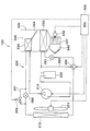
- FIG. 1 is an overall configuration diagram of an air conditioner according to an embodiment. It is sectional drawing of the electric compressor with which the inverter was integrated. It is the flowchart which showed the control content of air-conditioner control ECU or an inverter. It is the flowchart which showed the content of 1st low temperature environment control. It is the flowchart which showed the content of 2nd low temperature environment control. It is the figure which showed the change of component temperature before and after stopping operation
- the air conditioner according to the present embodiment is mounted on a vehicle and controls air conditioning in the vehicle interior by a heat pump cycle.
- the heat pump cycle 200 heats or cools the air (blowing air) blown into the vehicle interior, which is the air-conditioning target space. Therefore, in this heat pump cycle 200, by switching the refrigerant flow path, heating operation (heating operation) in which the air that is the heat exchange target fluid is heated and the vehicle interior is heated as normal environment control, and the air is cooled and the vehicle is cooled. A cooling operation (cooling operation) for cooling the room can be performed.
- a normal chlorofluorocarbon refrigerant is adopted as the refrigerant, and a subcritical refrigeration cycle in which the high-pressure side refrigerant pressure does not exceed the critical pressure of the refrigerant is configured.
- This refrigerant is mixed with refrigerating machine oil for lubricating the electric compressor 210, and a part of the refrigerating machine oil circulates in the cycle together with the refrigerant.
- the electric compressor 210 is disposed in the engine room, and inhales, compresses and discharges the refrigerant in the heat pump cycle 200. Specifically, as shown in FIG. 2, the electric compressor 210 has a configuration in which an inverter 220 is integrated with a housing 211.
- the housing 211 is a housing in which a refrigerant circulation space is formed, and has a refrigerant inlet 212 and a refrigerant outlet 213.
- the refrigerant sucked from the refrigerant suction port 212 flows through the refrigerant circulation space and is discharged from the refrigerant discharge port 213.
- the housing 211 houses an electric motor 210a and a compression mechanism 201b that compresses the refrigerant in the refrigerant circulation space.
- specific structures of the electric motor 210a and the compression mechanism 210b are omitted.
- the operation (rotation speed) of the electric motor 210a is controlled by driving the inverter 220 based on a control signal from an air conditioner control ECU 300 described later.
- air conditioner control ECU 300 is simply referred to as ECU 300.
- the electric motor 210a may employ either an AC motor or a DC motor.
- the compression mechanism 210b compresses the refrigerant and is driven by the electric motor 210a.
- a scroll type compression mechanism is employed as the compression mechanism 210b, but other mechanisms may be employed.
- the ECU 300 outputs a control signal for instructing the target rotational speed to the inverter 220, and the inverter 220 controls the rotational speed of the electric motor 210a, whereby the refrigerant discharge capacity of the compression mechanism 210b is adjusted. That is, when the rotation speed of the electric motor 210a is increased, the flow rate (flow velocity) of the refrigerant flowing through the refrigerant circulation space of the housing 211 increases. As a result, the refrigerant discharge capacity of the compression mechanism 210b increases. On the other hand, when the rotation speed of the electric motor 210a is reduced, the flow rate of the refrigerant flowing through the refrigerant circulation space of the housing 211 is reduced. As a result, the refrigerant discharge capacity of the compression mechanism 210b decreases.
- the inverter 220 is housed in a groove 214 provided on the refrigerant inlet side 212 of the refrigerant in the housing 211.
- the inverter 220 includes a heat sink 222, a power element 224, and a circuit board 225.
- the heat sink 222 is disposed in the groove 214 via the heat radiation grease 221.
- the power element 224 is disposed on the heat sink 222 via the heat dissipation grease 223.
- a power element 224 is mounted on the circuit board 225.
- the inverter 220 includes electronic components (not shown) such as a microcomputer. Inverter 220 drives power element 224 in accordance with a control signal input from ECU 300. By driving the power element 224, the electric motor 210a rotates.
- the heat sink 222 is pressed against the bottom of the groove 214 by the lid 215 and is fixed to the groove 214 by the screw 216. As a result, the inverter 220 is accommodated in the housing 211.
- the heat generated by the power element 224 is transmitted to the housing 211 via the heat radiation grease 223, the heat sink 222, and the heat radiation grease 221.
- the housing 211 sucks the refrigerant from the refrigerant suction port 212
- the heat of the power element 224 is absorbed by the refrigerant. That is, the inverter 220 is integrated with the electric compressor 210 so as to be cooled by the refrigerant sucked from the refrigerant suction port 212 of the electric compressor 210.
- a temperature detection element 226 for detecting the temperature of the inverter 220 is mounted on the circuit board 225 of the inverter 220.
- the temperature detection element 226 is, for example, a thermistor. Temperature detection element 226 outputs a temperature signal to ECU 300. Note that the temperature detection element 226 may not be mounted on the circuit board 225. That is, as long as the temperature of the inverter 220 can be detected, it may be disposed anywhere in the groove 214 of the housing 211.
- the indoor condenser 230 is disposed in the casing 241 of the indoor air conditioning unit 240 of the air conditioner 100, and heat exchanger for heating that exchanges heat between the high-temperature and high-pressure refrigerant flowing through the interior and the air after passing through the evaporator 250 described later. It is.
- the detailed configuration of the indoor air conditioning unit 240 will be described later.
- a heating expansion valve 260 is connected to the refrigerant outlet side of the indoor condenser 230 as a decompression section for heating operation that decompresses and expands the refrigerant flowing out of the indoor condenser 230 during the heating operation.
- the refrigerant inlet side of the outdoor condenser 270 is connected to the outlet side of the heating expansion valve 260.
- a bypass passage 261 is connected to the refrigerant outlet side of the indoor condenser 230 to guide the refrigerant flowing out of the indoor condenser 230 to the outdoor condenser 270 side by bypassing the heating expansion valve 260.
- a two-way valve 262 that opens and closes the bypass passage 261 is disposed in the bypass passage 261.
- the two-way valve 262 is an electromagnetic valve whose opening / closing operation is controlled by a control voltage output from the ECU 300, and is a refrigerant flow switching unit.
- the pressure loss that occurs when the refrigerant passes through the two-way valve 262 is extremely small with respect to the pressure loss that occurs when the refrigerant passes through the heating expansion valve 260. Therefore, the refrigerant flowing out of the indoor condenser 230 flows into the outdoor condenser 270 via the bypass passage 261 when the two-way valve 262 is open, and expands for heating when the two-way valve 262 is closed. It flows into the outdoor capacitor 270 through the valve 260. Thereby, the two-way valve 262 can switch the refrigerant flow path of the heat pump cycle 200.
- the outdoor condenser 270 exchanges heat between the low-pressure refrigerant circulating inside and the outside air blown from the outdoor fan 271.
- the outdoor condenser 270 is disposed in the engine room and functions as an evaporator that evaporates the low-pressure refrigerant and exerts an endothermic effect during the heating operation, and functions as a radiator that radiates heat from the high-pressure refrigerant during the cooling operation. It is an exchanger.
- the outdoor fan 271 is an electric blower in which the operating rate, that is, the rotation speed (the amount of air to be blown) is controlled by the control voltage output from the ECU 300.
- An electric three-way valve 280 is connected to the outlet side of the outdoor capacitor 270.
- the operation of the three-way valve 280 is controlled by a control voltage output from the ECU 300, and constitutes a refrigerant flow path switching unit in the same manner as the two-way valve 262 described above.
- the three-way valve 280 switches to a refrigerant flow path that connects an outlet side of the outdoor condenser 270 and an inlet side of an accumulator 290 described later during heating operation.
- the three-way valve 280 switches to a refrigerant flow path that connects the outlet side of the outdoor condenser 270 and the inlet side of the cooling expansion valve 281 during the cooling operation.
- the cooling expansion valve 281 is a decompression unit for cooling operation (for cooling operation) that decompresses and expands the refrigerant that flows out of the outdoor condenser 270 during the cooling operation, and the basic configuration thereof is the same as that of the heating expansion valve 260. .
- the refrigerant inlet side of the evaporator 250 is connected to the outlet side of the cooling expansion valve 281.
- the evaporator 250 is disposed in the casing 241 of the indoor air conditioning unit 240 on the upstream side of the air flow with respect to the indoor condenser 230, and performs heat exchange between the refrigerant circulating in the interior and the air to cool the air. It is a heat exchanger.
- the refrigerant outlet side of the evaporator 250 is connected to the inlet side of the accumulator 290.
- the refrigerant flow path from the three-way valve 280 through which the refrigerant during heating operation flows to the inlet side of the accumulator 290 constitutes a bypass passage 282 through which the refrigerant on the downstream side of the outdoor condenser 270 flows around the evaporator 250.
- the three-way valve 280 is a bypass passage switching unit that switches between a refrigerant circuit that guides the refrigerant downstream of the outdoor condenser 270 to the evaporator 250 side and a refrigerant circuit that guides the refrigerant downstream of the outdoor condenser 270 to the bypass passage 282 side. Is configured.
- the accumulator 290 is a gas-liquid separator for a low-pressure side refrigerant that separates the gas-liquid refrigerant flowing into the accumulator 290 and stores excess refrigerant in the cycle.
- the suction side of the electric compressor 210 is connected to the gas-phase refrigerant outlet of the accumulator 290. Therefore, the accumulator 290 suppresses the liquid refrigerant from being sucked into the electric compressor 210 and prevents liquid compression of the electric compressor 210.
- the indoor air conditioning unit 240 is disposed inside the instrument panel (instrument panel) at the foremost part of the vehicle interior, and houses the blower 242, the aforementioned indoor condenser 230, the evaporator 250, and the like in a casing 241 that forms the outer shell thereof. Is.
- the casing 241 forms an air passage for air to be blown into the passenger compartment, and is formed of a resin (for example, polypropylene) having a certain degree of elasticity and excellent strength.
- An inside / outside air switching device 243 that switches and introduces vehicle interior air (inside air) and outside air is disposed on the most upstream side of the air flow in the casing 241.
- the inside / outside air switching device 243 continuously adjusts the opening area of the inside air introduction port through which the inside air is introduced into the casing 241 and the outside air introduction port through which the outside air is introduced by the inside / outside air switching door, and the introduction ratio of the inside air to the outside air
- the inside / outside air switching device 243 is formed with an inside air introduction port for introducing inside air into the casing 241 and an outside air introduction port for introducing outside air. Furthermore, inside / outside air switching device 243 has an inside / outside air switching door that continuously adjusts the opening area of the inside air introduction port and the outside air introduction port to change the air volume ratio between the inside air volume and the outside air volume. Has been.
- the inside / outside air switching door is driven by an electric actuator (not shown) whose operation is controlled by a control signal output from the ECU 300.
- the suction port mode switched by the inside / outside air switching device 243 there is an inside air mode in which the inside air introduction port is fully opened and the outside air introduction port is fully closed to introduce the inside air into the casing 241.
- an outside air mode in which the inside air introduction port is fully closed and the outside air introduction port is fully opened to introduce outside air into the casing 241
- an inside and outside air mixing mode in which the inside air introduction port and the outside air introduction port are simultaneously opened.
- a blower 242 that blows air sucked through the inside / outside air switching device 243 toward the vehicle interior is disposed on the downstream side of the air flow of the inside / outside air switching device 243.
- the blower 242 is an electric blower that drives a centrifugal multiblade fan (sirocco fan) with a motor, and the number of rotations (the amount of blown air) is controlled by a control voltage output from the ECU 300.
- Evaporator 250 and indoor condenser 230 are arranged in this order with respect to the air flow on the air flow downstream side of blower 242.
- the evaporator 250 is arranged on the upstream side of the air flow with respect to the indoor condenser 230.
- the air mix door 244 that adjusts the air volume ratio that passes through the indoor condenser 230 in the air that has passed through the evaporator 250.
- a mixing space 245 for mixing the air heated by exchanging heat with the refrigerant in the indoor condenser 230 and the air not heated by bypassing the indoor condenser 230 is provided on the downstream side of the air flow of the indoor condenser 230. It has been.
- the most downstream part of the air flow of the casing 241 is provided with an opening hole for blowing the air merged in the mixing space 245 into the passenger compartment as a cooling target space as conditioned air. Therefore, the temperature of the air mixed in the mixing space 245 is adjusted by adjusting the ratio of the air volume that the air mix door 244 passes through the indoor condenser 230, and the temperature of the air blown out from the opening hole is adjusted. . That is, the air mix door 244 constitutes a temperature adjustment unit that adjusts the temperature of air (air conditioned air) blown into the vehicle interior.
- the air mix door 244 serves as a heat exchange amount adjustment unit that adjusts the heat exchange amount between the refrigerant discharged from the electric compressor 210 and the air blown into the vehicle interior in the indoor condenser 230 that constitutes the use side heat exchanger. Fulfills the function.
- the air mix door 244 is driven by a servo motor (not shown) whose operation is controlled by a control signal output from the ECU 300.
- the ECU 300 is an electronic control unit (ECU) including a known microcomputer including a CPU, a ROM, a RAM, and the like and a peripheral circuit thereof.
- ECU electronice control unit
- ECU 300 inputs sensor signals from a group of sensors for air conditioning control such as an inside air sensor, an outside air sensor, a solar radiation sensor, and a high pressure side pressure sensor (not shown). Further, the ECU 300 receives operation signals of various air conditioning operation switches from an operation panel (not shown) disposed near the instrument panel in the front part of the vehicle interior. ECU 300 performs various calculations and processes according to the air conditioning control program stored in the ROM. Thereby, ECU300 outputs a control signal to various air-conditioning control apparatuses, such as inverter 220 of electric compressor 210, two-way valve 262, outdoor fan 271, three-way valve 280, and air blower 242, and controls operation of each apparatus. .
- the above is the overall configuration of the air conditioner 100 according to the present embodiment.
- the air conditioner 100 starts the processing shown in FIG. 3 when the user operates the operation panel in the passenger compartment.
- the contents shown in FIGS. 3 to 5 can be implemented in a microcomputer mounted on the inverter 220, the present embodiment will be described as the control of the ECU 300.
- the ECU 300 acquires the component temperature of the inverter 220 (S400). That is, ECU 300 receives a temperature signal from temperature detection element 226 mounted on inverter 220. Then, ECU 300 determines whether or not the component temperature of inverter 220 is lower than a predetermined first reference temperature Ta1 (S410).
- the first reference temperature Ta1 is a temperature that may cause overcooling of the inverter when the component temperature of the inverter 220 is cooled to a level lower than the temperature. Accordingly, the first reference temperature Ta1 is set to a temperature higher than the minimum guaranteed temperature of each component constituting the inverter 220 (see FIG. 6 described later). Since the inverter 220 includes a plurality of electronic components such as the power element 224, the minimum guaranteed temperature of the inverter 220 is the highest minimum guaranteed temperature among the components.
- the ECU 300 When the component temperature of the inverter 220 is higher than the first reference temperature Ta1, the ECU 300 performs normal environmental control (S420). Specifically, first, ECU 300 calculates a target blowing temperature, which is a target temperature of air blown into the vehicle interior, based on the above-described sensor signals and operation signals of the operation panel. Then, ECU 300 performs feedback control for adjusting the rotational speed of electric compressor 210 and the like so that the target blowing temperature coincides with the actual blowing temperature that is the actual temperature in the passenger compartment.
- a target blowing temperature which is a target temperature of air blown into the vehicle interior
- the ECU 300 closes the two-way valve 262 and switches the three-way valve 280 to a refrigerant flow path that connects the outlet side of the outdoor capacitor 270 and the inlet side of the accumulator 290.
- the heat pump cycle 200 is switched to the refrigerant flow path through which the refrigerant flows, such as the electric compressor 210, the indoor condenser 230, the heating expansion valve 260, the outdoor condenser 270, the three-way valve 280, the accumulator 290, and the electric compressor 210. .
- the high-pressure refrigerant discharged from the electric compressor 210 flows into the indoor condenser 230.
- the refrigerant flowing into the indoor condenser 230 exchanges heat with the air blown from the blower 242 and passed through the evaporator 250 to dissipate heat. Thereby, air is heated.
- the ECU 300 opens the two-way valve 262 and switches the three-way valve 280 to a refrigerant flow path that connects the outlet side of the outdoor condenser 270 and the inlet side of the cooling expansion valve 281.
- the heat pump cycle 200 includes a refrigerant such as an electric compressor 210, an indoor condenser 230, a two-way valve 262, an outdoor condenser 270, a three-way valve 280, a cooling expansion valve 281, an evaporator 250, an accumulator 290, and an electric compressor 210. Is switched to the refrigerant flow path.
- the high-pressure refrigerant discharged from the electric compressor 210 flows into the indoor condenser 230 and exchanges heat with the air blown from the blower 242 and passed through the evaporator 250 to dissipate heat. .
- the high-pressure refrigerant that has flowed out of the indoor condenser 230 flows into the outdoor condenser 270 via the bypass passage 261 because the two-way valve 262 is open.
- the low-pressure refrigerant that has flowed into the outdoor condenser 270 further dissipates heat to the outside air blown by the outdoor fan 271.
- the three-way valve 280 switches to the refrigerant flow path that connects the outlet side of the outdoor condenser 270 and the inlet side of the cooling expansion valve 281.
- the refrigerant flowing out of the outdoor condenser 270 is decompressed and expanded by the cooling expansion valve 281.
- the refrigerant that has flowed out of the cooling expansion valve 281 flows into the evaporator 250 and absorbs heat from the air blown by the blower 242 and evaporates. Thereby, air is cooled.
- the ECU 300 acquires the component temperature of the inverter 220 again, and repeatedly executes the normal environment control described above if the component temperature is higher than the first reference temperature Ta1.
- the ECU 300 is one of control for reducing the self-cooling amount of the electric compressor 210 (second low-temperature environment control) and control for increasing the self-heat generation amount of the inverter 220 (first low-temperature environment control). One or both controls are performed on the inverter 220.
- control for reducing the self-cooling amount of the electric compressor 210 is control for reducing the ability to cool the inverter 220 by the refrigerant flowing into the electric compressor 210.
- control for increasing the self-heat generation amount of the inverter 220 is control for increasing the heat generation amount of the inverter 220 by increasing the electrical operation amount of the inverter 220.
- the ECU 300 determines whether or not a stop signal is received (S430).
- the stop signal is a signal indicating that the air conditioning control is stopped.
- the ECU 300 receives a stop signal from the operation panel, another ECU, or the like when the user operates the operation panel to stop the air conditioning in the vehicle interior or when the power supply of the vehicle is stopped.
- ECU300 performs 1st low temperature environment control, when the stop signal is not received (S440).
- the component temperature of the inverter 220 is lower than the first reference temperature Ta1
- the vehicle is placed in an environment where the outside air temperature is very low, and the user usually uses heating. Therefore, when the first low-temperature environment control is executed, it is assumed that the air conditioner 100 is performing a heating operation.
- the contents of the first low-temperature environment control will be described with reference to FIG.
- the ECU 300 determines whether or not the heating capacity of the electric compressor 210 can be limited (S441).
- the ECU 300 determines the determination based on, for example, the remaining battery capacity. When the remaining capacity of the battery is higher than a predetermined value, it is possible to limit the heating capacity. When the remaining capacity of the battery is lower than the predetermined value, it is difficult to limit the heating capacity. In addition, you may determine the restriction
- the ECU 300 controls the inverter 220 so that the rotation of the electric compressor 210 is decelerated (S442). That is, the rotational speed of the electric motor 210a of the electric compressor 210 is reduced. Thereby, since the flow volume of the refrigerant
- ECU 300 determines whether or not the efficiency of heat pump cycle 200 can be reduced (S443).
- the ECU 300 determines the determination based on, for example, the remaining battery capacity. When the remaining capacity of the battery is higher than a predetermined value, the efficiency of the heat pump cycle 200 can be reduced. When the remaining capacity of the battery is lower than the predetermined value, it is difficult to reduce the efficiency of the heat pump cycle 200. is there. In addition, you may determine the possibility of the efficiency fall of the heat pump cycle 200 using another criterion.
- the ECU 300 drives the inverter 220 so that the switching speed of the inverter 220 is increased (S444). That is, by increasing the switching frequency of the power element 224, the switching loss of the power element 224 increases, and the power element 224 generates heat. Thereby, since inverter 220 itself generates heat, the amount of self-heating of inverter 220 increases. Therefore, overcooling of the inverter 220 can be prevented.
- the ECU 300 returns to S400 shown in FIG. 3 and acquires the component temperature of the inverter 220 again.
- ECU 300 drives inverter 220 so that the switching speed of inverter 220 increases, so that the self-heat generation amount of inverter 220 is increased. To raise.
- ECU 300 determines that it is difficult to reduce the efficiency of heat pump cycle 200 after decelerating the rotation of electric compressor 210, ECU 300 ends the first low-temperature environment control and is shown in FIG. Return to S400.
- the second low temperature environment control is executed (S430, 450).
- the content of the second low-temperature environment control will be described with reference to FIG.
- the ECU 300 determines whether or not the rotation of the electric compressor 210 can be stopped at a reduced speed (S451). The ECU 300 determines the determination based on, for example, whether or not a special flag is set.
- the special flag refers to the electric motor 210a of the electric compressor 210, such as when a high voltage is used during traveling of the vehicle, when the power of the vehicle is turned off, when an abnormality occurs in the heat pump cycle 200, or the like. This flag stands when it is difficult to control the rotation.
- the special flag is not set, the rotation of the electric motor 210a of the electric compressor 210 can be stopped at a reduced speed, and when the special flag is set, the rotation of the electric compressor 210 is reduced at a reduced speed. It is difficult to stop.
- the ECU 300 controls the inverter 220 so that the rotation of the electric motor 210a of the electric compressor 210 is gently stopped (S452). That is, normally, when the electric compressor 210 is stopped, the electric motor 210a is suddenly stopped, but here, the electric motor 210a is stopped while being loosened so that the electric motor 210a does not stop suddenly.
- the refrigerant continues to flow into the electric compressor 210 due to the inertia of the refrigerant, but the refrigerant flows into the electric compressor 210 by gently stopping the electric compressor 210.
- the flow rate can be reduced. That is, the amount of self-cooling of the electric compressor 210 decreases. Therefore, overcooling of the inverter 220 can be prevented.
- the ECU 300 acquires the component temperature of the inverter 220 (S453), and determines whether or not the component temperature of the inverter 220 is lower than a predetermined second reference temperature Ta2 (S454).
- the second reference temperature Ta2 is a component temperature at which the inverter 220 will not be supercooled after the electric compressor 210 is stopped, and is set, for example, between a component temperature in a low temperature environment and a minimum guaranteed temperature (described later). (See FIG. 6).
- the ECU 300 ends the second low temperature environment control.
- the ECU 300 performs control to cause the power element 224 of the inverter 220 to generate heat (S455). That is, ECU 300 causes power element 224 to generate heat by operating power element 224 so that electric motor 210a of electric compressor 210 does not rotate. That is, the warm-up control of the power element 224 is performed. Thereby, the self-heating amount of the inverter 220 increases. Therefore, overcooling of the inverter 220 can be prevented.
- ECU 300 obtains the component temperature of inverter 220 (S456), and determines whether or not the component temperature of inverter 220 is lower than a predetermined third reference temperature Ta3 (S457).
- the third reference temperature Ta3 is a component temperature at which the inverter 220 is likely to be overcooled after the electric compressor 210 is stopped, and is set between, for example, the third reference temperature Ta3 and the minimum guaranteed temperature (described later). (See FIG. 6).
- the ECU 300 ends the second low temperature environment control.
- the ECU 300 performs control to cause the power element 224 of the inverter 220 to generate heat again.
- the ECU 300 normally stops the electric compressor 210 (S458). That is, the electric motor 210a is suddenly stopped. Thereafter, the ECU 300 controls the power element 224 to generate heat until the component temperature of the inverter 220 becomes higher than the third reference temperature Ta3 (S455, S456, S457).
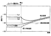
- the component temperature does not fall below the minimum guaranteed temperature by the first low temperature environment control during the operation of the inverter 220 as shown in FIG.
- the inverter 220 is stopped by the stop signal, the self-cooling amount of the electric compressor 210 is decreased or the self-heat generation amount of the inverter 220 is increased by the second low temperature environment control. Therefore, the component temperature does not fall below the minimum guaranteed temperature after the inverter 220 is stopped.
- the refrigerant temperature sucked into the electric compressor 210 is the lowest.
- the heat sink 222 is cooled by the refrigerant and is lower than the minimum guaranteed temperature of the component temperature of the inverter 220.
- the suction refrigerant temperature and the temperature of the heat sink 222 become substantially the same as the component temperature when the inverter 220 is stopped.
- the ECU 300 increases the control for reducing the self-cooling amount of the electric compressor 210 and the self-heat generation amount of the inverter 220. Either or both of the controls are performed. As a result, the inverter 220 can be prevented from being overcooled by the refrigerant in a low temperature environment, and thus the inverter 220 can be prevented from being destroyed.
- the temperature detection element 226 of the present embodiment corresponds to the “temperature detection unit” of the present disclosure
- the ECU 300 corresponds to the “control unit” of the present disclosure
- an operation panel and other devices such as an ECU correspond to the “external device” of the present disclosure
- the first reference temperature Ta1 corresponds to the “reference temperature” of the present disclosure.
- the inverter 220 including the power element 224 and the circuit board 225 that are components for rotating the electric motor 210a of the electric compressor 210 in accordance with the control signal corresponds to the “drive unit” of the present disclosure.
- the configuration of the air conditioner 100 and the control content of the ECU 300 shown in each of the above embodiments are examples, and the present disclosure is not limited to the configuration described above, and other configurations that can realize the present disclosure can be employed.
- the control for decelerating the rotation of the electric motor 210a of the electric compressor 210 S442
- the control for increasing the switching speed of the inverter 220 S444
- the self-cooling amount of the electric compressor 210 can be reduced by the following control. For example, when operating in a one-stage heat pump cycle, there is a method of switching to a multistage compression cycle such as a gas injection cycle. Further, there is a method in which the refrigerant sucked into the electric compressor 210 is warmed by the outside air temperature by accelerating the rotation of the outdoor fan 271.
- the self-heat generation amount of the inverter 220 can be increased by the following control.
- two-phase modulation control is performed by the inverter 220
- the air conditioning control there is a method in which the refrigerant discharge pressure of the electric compressor 210 is increased by switching to the inside air circulation mode so that a high load state is obtained.
- the amount of refrigerant flowing into the electric compressor 210 is increased by increasing the rotational speed of the electric compressor 210, but the self-heat generation amount of the inverter 220 is further increased.
- a refrigerant shut-off valve is provided at the refrigerant inlet 212 of the electric compressor 210, and the refrigerant shut-off valve is closed when the electric compressor 210 is stopped, so that the refrigerant flows into the electric compressor 210. And the self-cooling amount of the electric compressor 210 can be reduced.
- the self-heating amount of the inverter 220 may be increased by energizing the electric motor 210a of the electric compressor 210 with an electrical angle at which the electric motor 210a does not rotate to generate heat in the power element 224 and the motor winding. it can.
- the ECU 300 performs the control combining the first low-temperature environment control and the second low-temperature environment control. However, only one of them may be performed.
- the ECU 300 performs the first low-temperature environment control and the second low-temperature environment control, and determines whether or not the execution is necessary.
- the first low-temperature environment control and the second low-temperature environment control may be performed and necessity determination may be performed by the microcomputer provided in the inverter 220 itself.
- the inverter 220 may be integrally provided with a control unit that performs the first low temperature environment control and the second low temperature environment control and determines whether or not to perform the first low temperature environment control.
- the air conditioner 100 is mounted on a vehicle, the air conditioner 100 is not limited to a vehicle.
Landscapes
- Engineering & Computer Science (AREA)
- Mechanical Engineering (AREA)
- General Engineering & Computer Science (AREA)
- Physics & Mathematics (AREA)
- Thermal Sciences (AREA)
- Compressor (AREA)
- Control Of Positive-Displacement Pumps (AREA)
- Inverter Devices (AREA)
- Air Conditioning Control Device (AREA)
- Air-Conditioning For Vehicles (AREA)
Abstract
空調装置は、電動圧縮機(210)、インバータ(220)、温度検出素子(226)、およびECU(300)を備える。電動圧縮機は、冷媒吸入口(212)から吸入した冷媒を圧縮して冷媒吐出口(213)から吐出する。インバータ(220)は、吸入された冷媒によって冷却されるように電動圧縮機(210)に一体化されていると共に、制御信号に従って電動圧縮機(210)を動作させる。温度検出素子(226)は、インバータ(220)の温度を検出する。ECU(300)は、制御信号を出力してインバータ(220)を制御する。ECU(300)は、温度検出素子(226)によって検出された温度が予め定められた基準温度(Ta1)よりも低い場合、電動圧縮機(210)の自己冷却量を低下させる制御、及び、インバータ(220)の自己発熱量を上昇させる制御のうちのいずれか一方または両方をインバータ(220)に対して行う。
Description
本出願は、当該開示内容が参照によって本出願に組み込まれた、2015年1月30日に出願された日本特許出願2015-016381号を基にしている。
本開示は、インバータが一体化された電動圧縮機を備える空調装置に関する。
冷媒温度を測定し、冷媒温度が所定の値より低い場合は圧縮機の上限回転数を制限することで液圧縮や潤滑不良が起こることを防止する空気調和装置が、例えば特許文献1で提案されている。圧縮機は、パワー素子等の電子部品を有するインバータの制御によって電動モータが回転することにより動作する。
ここで、インバータを構成する電子部品を循環冷媒によって冷却するために、インバータが圧縮機に一体化された構成が知られている。これにより、圧縮機に流入する冷媒によって電子部品が冷却される。
しかしながら、例えば低温環境下等の状況では、圧縮機に吸入される冷媒が電子部品の最低動作保証温度を下回ることがある。具体的には、圧縮機を停止させると、電子部品自身の発熱が無くなる一方、それまで循環していた冷媒が、その慣性により圧縮機に流入し続ける。これにより、電子部品が最低保証温度以下に過冷却され、ひいては破損してしまう恐れがある。
これを防止するためには、電子部品の温度が最低動作保証温度を下回るような場合に圧縮機の動作を停止させる保護機能を圧縮機に持たせることが考えられる。この場合、圧縮機の停止時の電子部品の温度降下を見越して、保護温度閾値を高めの温度に設定する必要がある。しかし、保護温度閾値を高く設定するということは、低温環境下では圧縮機を作動させないことに他ならない。そのため、低温環境下での電子部品の動作保証温度範囲が制限されてしまうという新たな不具合が生じてしまう。
本開示は上記点に鑑み、低温環境下において、インバータが一体化された電動圧縮機の過冷却によってインバータを構成する電子部品が破壊されてしまうことを防止することができる空調装置を提供することを目的とする。
本開示の空調装置は、電動圧縮機、駆動部、温度検出部、および制御部を備える。
電動圧縮機は、冷媒吸入口から吸入した冷媒を圧縮して冷媒吐出口から吐出する。駆動部は、電動圧縮機の冷媒吸入口から吸入された冷媒によって冷却されるように電動圧縮機に一体化されていると共に、制御信号に従って電動圧縮機を動作させる。温度検出部は、駆動部の温度を検出する。制御部は、制御信号を駆動部に出力して駆動部を制御する。
制御部は、温度検出部によって検出された温度が予め定められた基準温度よりも低い場合、電動圧縮機の自己冷却量を低下させる制御、及び、駆動部の自己発熱量を上昇させる制御のうちのいずれか一方または両方を駆動部に対して行う。
これによると、電動圧縮機の自己冷却量が低下するので、駆動部が冷媒によって冷やされすぎないようにすることができる。また、駆動部の自己発熱量が上昇するので、駆動部自身の温度を上昇させることができる。このため、低温環境下において、電動圧縮機の過冷却によって駆動部を構成する電子部品が最低保証温度を下回ることを回避することができる。したがって、駆動部の破損を防止することができる。
本開示についての上記目的およびその他の目的、特徴や利点は、添付の図面を参照しながら下記の詳細な記述により、より明確になる。
一実施形態に係る空調装置の全体構成図である。
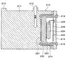
インバータが一体化された電動圧縮機の断面図である。
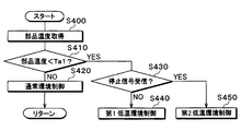
エアコン制御ECUまたはインバータの制御内容を示したフローチャートである。
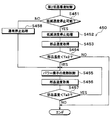
第1低温環境制御の内容を示したフローチャートである。
第2低温環境制御の内容を示したフローチャートである。
インバータの動作を停止させる前後で部品温度の変化を示した図である。
電動圧縮機の内部構造を概略的に示す断面図である。
以下、本開示の一実施形態について図に基づいて説明する。
以下、本開示の一実施形態について図を参照して説明する。本実施形態に係る空調装置は車両に搭載されると共に、ヒートポンプサイクルによって車室内の空調制御を行うものである。
図1に示された空調装置100において、ヒートポンプサイクル200は空調対象空間である車室内へ送風される空気(送風空気)を加熱あるいは冷却する。したがって、このヒートポンプサイクル200は、冷媒流路を切り替えることによって、通常環境制御として熱交換対象流体である空気を加熱して車室内を暖房する暖房運転(加熱運転)と、空気を冷却して車室内を冷房する冷房運転(冷却運転)とを実行できる。
また、本実施形態のヒートポンプサイクル200では、冷媒として通常のフロン系冷媒を採用しており、高圧側冷媒圧力が冷媒の臨界圧力を超えない亜臨界冷凍サイクルを構成している。この冷媒には電動圧縮機210を潤滑するための冷凍機油が混入されており、冷凍機油の一部は冷媒と共にサイクルを循環している。
まず、電動圧縮機210は、エンジンルーム内に配置されており、ヒートポンプサイクル200において冷媒を吸入し、圧縮して吐出するものである。具体的には、図2に示されるように、電動圧縮機210はハウジング211にインバータ220が一体化された構成になっている。
図7に示すように、ハウジング211は、冷媒流通空間が内部に形成された筐体であって、冷媒吸入口212および冷媒吐出口213を有している。冷媒吸入口212から吸入された冷媒は、冷媒流通空間を流通して、冷媒吐出口213から吐出される。また、ハウジング211は、冷媒流通空間内に電動モータ210aと冷媒を圧縮する圧縮機構201bとを収容している。なお、図2では電動モータ210a及び圧縮機構210bの具体的な構造を省略している。
電動モータ210aは、後述するエアコン制御ECU300による制御信号に基づくインバータ220の駆動によって、その作動(回転数)が制御される。なお、以下の説明では、エアコン制御ECU300を単にECU300と称する。電動モータ210aは、交流モータ、直流モータのいずれの形式が採用されても良い。圧縮機構210bは冷媒を圧縮するものであり、電動モータ210aによって駆動される。本実施形態では、圧縮機構210bとしてスクロール型圧縮機構が採用されているが、他の機構が採用されてもよい。そして、ECU300からインバータ220へ目標回転数を指示する制御信号が出力され、インバータ220が電動モータ210aの回転数を制御することによって、圧縮機構210bの冷媒吐出能力が調整される。すなわち、電動モータ210aの回転数を高めると、ハウジング211の冷媒流通空間を流通する冷媒の流量(流速)が大きくなる。その結果、圧縮機構210bの冷媒吐出能力が上昇する。一方、電動モータ210aの回転数を小さくすると、ハウジング211の冷媒流通空間を流通する冷媒の流量が小さくなる。その結果、圧縮機構210bの冷媒吐出能力は下降する。
インバータ220は、ハウジング211のうち冷媒の冷媒吸入口212側に設けられた溝部214に収容されている。インバータ220は、ヒートシンク222、パワー素子224、および回路基板225を備えている。ヒートシンク222は、放熱グリス221を介して溝部214に配置されている。パワー素子224は、放熱グリス223を介してヒートシンク222に配置されている。回路基板225には、パワー素子224が実装されている。この他、インバータ220はマイクロコンピュータ等の図示しない電子部品も備えている。インバータ220は、ECU300から入力される制御信号に従ってパワー素子224を駆動する。このパワー素子224が駆動することで、電動モータ210aが回転する。
なお、ヒートシンク222は蓋部215によって溝部214の底部に押さえ付けられていると共に、ネジ216によって溝部214に固定されている。これにより、インバータ220はハウジング211に収容されている。
また、パワー素子224の発熱は、放熱グリス223、ヒートシンク222、及び放熱グリス221を介してハウジング211に伝わる。上述のように、ハウジング211は冷媒吸入口212から冷媒を吸入しているので、パワー素子224の熱は冷媒に吸収される。すなわち、インバータ220は、電動圧縮機210の冷媒吸入口212から吸入された冷媒によって冷却されるように電動圧縮機210に一体化されている。
ここで、インバータ220の回路基板225には、インバータ220の温度を検出するための温度検出素子226が実装されている。温度検出素子226は、例えばサーミスタである。温度検出素子226は、温度信号をECU300に出力する。なお、温度検出素子226は回路基板225に実装されていなくても良い。すなわち、インバータ220の温度を検出できればハウジング211の溝部214のどこに配置されていても良い。
図1に示された電動圧縮機210の冷媒吐出口213には、利用側熱交換器としての室内コンデンサ230の冷媒入口側が接続されている。室内コンデンサ230は、空調装置100の室内空調ユニット240のケーシング241内に配置されており、その内部を流通する高温高圧冷媒と後述するエバポレータ250通過後の空気とを熱交換させる加熱用熱交換器である。なお、室内空調ユニット240の詳細構成については後述する。
室内コンデンサ230の冷媒出口側には、暖房運転時に室内コンデンサ230から流出した冷媒を減圧膨張させる暖房運転用の減圧部としての暖房用膨張弁260が接続されている。暖房用膨張弁260の出口側には、室外コンデンサ270の冷媒入口側が接続されている。
さらに、室内コンデンサ230の冷媒出口側には、室内コンデンサ230から流出した冷媒を、暖房用膨張弁260を迂回させて室外コンデンサ270側へ導く迂回通路261が接続されている。この迂回通路261には、迂回通路261を開閉する二方弁262が配置されている。二方弁262は、ECU300から出力される制御電圧によってその開閉作動が制御される電磁弁であり、冷媒流路切替部である。
また、冷媒が二方弁262を通過する際に生じる圧力損失は、暖房用膨張弁260を通過する際に生じる圧力損失に対して極めて小さい。したがって、室内コンデンサ230から流出した冷媒は、二方弁262が開いている場合には迂回通路261側を介して室外コンデンサ270へ流入し、二方弁262が閉じている場合には暖房用膨張弁260を介して室外コンデンサ270へ流入する。これにより、二方弁262は、ヒートポンプサイクル200の冷媒流路を切り替えることができる。
室外コンデンサ270は、内部を流通する低圧冷媒と室外ファン271から送風された外気とを熱交換させるものである。この室外コンデンサ270は、エンジンルーム内に配置されて、暖房運転時には、低圧冷媒を蒸発させて吸熱作用を発揮させる蒸発器として機能し、冷房運転時には、高圧冷媒を放熱させる放熱器として機能する熱交換器である。
また、室外ファン271は、ECU300から出力される制御電圧によって稼働率、すなわち回転数(送風する空気量)が制御される電動式送風機である。
室外コンデンサ270の出口側には、電気式の三方弁280が接続されている。この三方弁280は、ECU300から出力される制御電圧によって、その作動が制御されるものであり、上述した二方弁262と同様に冷媒流路切替部を構成している。
具体的には、三方弁280は、暖房運転時には、室外コンデンサ270の出口側と後述するアキュムレータ290の入口側とを接続する冷媒流路に切り替える。一方、三方弁280は、冷房運転時には、室外コンデンサ270の出口側と冷房用膨張弁281の入口側とを接続する冷媒流路に切り替える。
冷房用膨張弁281は、冷房運転時に室外コンデンサ270から流出した冷媒を減圧膨張させる冷房運転用(冷却運転用)の減圧部であり、その基本的構成は、暖房用膨張弁260と同様である。冷房用膨張弁281の出口側には、エバポレータ250の冷媒入口側が接続されている。
エバポレータ250は、室内空調ユニット240のケーシング241内のうち、室内コンデンサ230よりも空気流れの上流側に配置されて、その内部を流通する冷媒と空気とを熱交換させ、空気を冷却する冷却用熱交換器である。エバポレータ250の冷媒出口側には、アキュムレータ290の入口側が接続されている。
したがって、暖房運転時の冷媒が流通する三方弁280からアキュムレータ290の入口側へ至る冷媒流路は、室外コンデンサ270の下流側の冷媒をエバポレータ250を迂回させて流す迂回通路282を構成している。さらに、三方弁280は、室外コンデンサ270の下流側の冷媒をエバポレータ250側へ導く冷媒回路と、室外コンデンサ270の下流側の冷媒を迂回通路282側へ導く冷媒回路と、を切り替える迂回通路切替部を構成している。
アキュムレータ290は、その内部に流入した冷媒の気液を分離して、サイクル内の余剰冷媒を蓄える低圧側冷媒用の気液分離器である。アキュムレータ290の気相冷媒出口には、電動圧縮機210の吸入側が接続されている。したがって、このアキュムレータ290は、電動圧縮機210に液相冷媒が吸入されてしまうことを抑制して、電動圧縮機210の液圧縮を防止する。
次に、室内空調ユニット240について説明する。室内空調ユニット240は、車室内最前部の計器盤(インストルメントパネル)の内側に配置されて、その外殻を形成するケーシング241内に送風機242、前述の室内コンデンサ230、エバポレータ250等を収容したものである。
ケーシング241は、車室内に送風される空気の空気通路を形成しており、ある程度の弾性を有し、強度的にも優れた樹脂(例えば、ポリプロピレン)にて成形されている。ケーシング241内の空気流れ最上流側には、車室内空気(内気)と外気とを切替導入する内外気切替装置243が配置されている。
内外気切替装置243は、ケーシング241内に内気を導入させる内気導入口及び外気を導入させる外気導入口の開口面積を、内外気切替ドアによって連続的に調整して、内気と外気との導入割合を連続的に変化させて吸込口モードを切り替える内外気切替部である。
内外気切替装置243には、ケーシング241内に内気を導入させる内気導入口及び外気を導入させる外気導入口が形成されている。さらに、内外気切替装置243の内部には、内気導入口及び外気導入口の開口面積を連続的に調整して、内気の風量と外気の風量との風量割合を変化させる内外気切替ドアが配置されている。この内外気切替ドアは、ECU300から出力される制御信号によって作動が制御される図示しない電動アクチュエータによって駆動される。
内外気切替装置243によって切り替えられる吸込口モードとしては、内気導入口を全開とすると共に外気導入口を全閉としてケーシング241内へ内気を導入する内気モードがある。また、内気導入口を全閉とすると共に外気導入口を全開としてケーシング241内へ外気を導入する外気モード、さらに、内気導入口及び外気導入口を同時に開く内外気混入モードがある。
内外気切替装置243の空気流れ下流側には、内外気切替装置243を介して吸入された空気を車室内へ向けて送風する送風機242が配置されている。この送風機242は、遠心多翼ファン(シロッコファン)をモータにて駆動する電動送風機であって、ECU300から出力される制御電圧によって回転数(送風量)が制御される。
送風機242の空気流れ下流側には、エバポレータ250及び室内コンデンサ230が、空気の流れに対して、この順に配置されている。換言すると、エバポレータ250は、室内コンデンサ230に対して、空気の流れ上流側に配置されている。
さらに、エバポレータ250の空気流れ下流側であって、かつ、室内コンデンサ230の空気流れ上流側には、エバポレータ250通過後の空気のうち、室内コンデンサ230を通過させる風量割合を調整するエアミックスドア244が配置されている。また、室内コンデンサ230の空気流れ下流側には、室内コンデンサ230にて冷媒と熱交換して加熱された空気と室内コンデンサ230を迂回して加熱されていない空気とを混合させる混合空間245が設けられている。
ケーシング241の空気流れ最下流部には、混合空間245にて合流した空気を、空調風として冷却対象空間である車室内へ吹き出す開口穴が設けられている。したがって、エアミックスドア244が室内コンデンサ230を通過させる風量の割合を調整することによって、混合空間245にて混合された空気の温度が調整され、開口穴から吹き出される空気の温度が調整される。つまり、エアミックスドア244は、車室内へ送風される空気(空調風)の温度を調整する温度調整部を構成している。
換言すると、エアミックスドア244は、利用側熱交換器を構成する室内コンデンサ230において、電動圧縮機210吐出冷媒と車室内に送風される空気との熱交換量を調整する熱交換量調整部としての機能を果たす。なお、エアミックスドア244は、ECU300から出力される制御信号によって作動が制御される図示しないサーボモータによって駆動される。
ECU300は、CPU、ROM及びRAM等を含む周知のマイクロコンピュータとその周辺回路を含む電子制御装置(Electronic Control Unit;ECU)である。
ECU300は、図示しない内気センサ、外気センサ、日射センサ、高圧側圧力センサ等の空調制御用のセンサ群からセンサ信号を入力する。さらに、ECU300には、車室内前部の計器盤付近に配置された図示しない操作パネルから各種空調操作スイッチの操作信号を入力する。そして、ECU300は、ROMに記憶された空調制御プログラムに従って各種演算、処理を行う。これにより、ECU300は、電動圧縮機210のインバータ220、二方弁262、室外ファン271、三方弁280、及び送風機242等の各種空調制御機器に制御信号を出力して各機器の作動を制御する。以上が、本実施形態に係る空調装置100の全体構成である。
次に、空調装置100の作動について説明する。空調装置100は、ユーザによって車室内の操作パネルが操作されることで図3に示された処理を開始する。なお、図3から図5に示された内容はインバータ220に搭載されたマイクロコンピュータにおいても実施可能であるが、本実施形態ではECU300の制御として説明する。
まず、ECU300は、インバータ220の部品温度を取得する(S400)。すなわち、ECU300は、インバータ220に実装された温度検出素子226から温度信号を受信する。そして、ECU300は、インバータ220の部品温度が予め定められた第1基準温度Ta1よりも低いか否かを判定する(S410)。
第1基準温度Ta1は、インバータ220の部品温度が当該温度を下回る程度に冷却された場合にインバータの過冷却となるおそれがある温度である。したがって、第1基準温度Ta1は、インバータ220を構成する各部品の最低保証温度よりも高い温度に設定されている(後述する図6参照)。なお、インバータ220はパワー素子224等の複数の電子部品によって構成されているので、インバータ220の最低保証温度は各部品のうち最も高い最低保証温度とする。
インバータ220の部品温度が第1基準温度Ta1よりも高い場合、ECU300は通常環境制御を行う(S420)。具体的には、まず、ECU300が上述の各センサ信号及び操作パネルの操作信号に基づいて車室内へ吹き出す空気の目標温度である目標吹出温度を算出する。そして、ECU300は、目標吹出温度が車室内の実際の温度である実際吹出温度に一致するように電動圧縮機210の回転数等を調整するフィードバック制御を行う。
例えば、暖房運転の場合、ECU300は二方弁262を閉じると共に、三方弁280を室外コンデンサ270の出口側とアキュムレータ290の入口側とを接続する冷媒流路に切り替える。これにより、ヒートポンプサイクル200は、電動圧縮機210、室内コンデンサ230、暖房用膨張弁260、室外コンデンサ270、三方弁280、アキュムレータ290、電動圧縮機210というように冷媒が流れる冷媒流路に切り替えられる。
このような暖房運転時のヒートポンプサイクル200では、電動圧縮機210から吐出された高圧冷媒が室内コンデンサ230へ流入する。室内コンデンサ230へ流入した冷媒は、送風機242から送風されてエバポレータ250を通過した空気と熱交換して放熱する。これにより、空気が加熱される。
一方、冷房運転の場合、ECU300は二方弁262を開くと共に、三方弁280を室外コンデンサ270の出口側と冷房用膨張弁281の入口側とを接続する冷媒流路に切り替える。これにより、ヒートポンプサイクル200は、電動圧縮機210、室内コンデンサ230、二方弁262、室外コンデンサ270、三方弁280、冷房用膨張弁281、エバポレータ250、アキュムレータ290、電動圧縮機210というように冷媒が流れる冷媒流路に切り替えられる。
このような冷房運転時のヒートポンプサイクル200では、電動圧縮機210から吐出された高圧冷媒が室内コンデンサ230へ流入して、送風機242から送風されてエバポレータ250を通過した空気と熱交換して放熱する。室内コンデンサ230から流出した高圧冷媒は、二方弁262が開いているので、迂回通路261を介して室外コンデンサ270へ流入する。室外コンデンサ270へ流入した低圧冷媒は、室外ファン271によって送風された外気にさらに放熱する。
そして、三方弁280が室外コンデンサ270の出口側と冷房用膨張弁281の入口側とを接続する冷媒流路に切り替えている。これにより、室外コンデンサ270から流出した冷媒は、冷房用膨張弁281にて減圧膨張される。冷房用膨張弁281から流出した冷媒は、エバポレータ250へ流入して、送風機242によって送風された空気から吸熱して蒸発する。これにより、空気が冷却される。
そして、ECU300は、再びインバータ220の部品温度を取得し、部品温度が第1基準温度Ta1よりも高ければ上記の通常環境制御を繰り返し実行する。
また、インバータ220の部品温度が第1基準温度Ta1よりも低い場合、インバータ220の温度が最低保証温度を下回る可能性がある。このため、ECU300は、電動圧縮機210の自己冷却量を低下させる制御(第2低温環境制御)、及び、インバータ220の自己発熱量を上昇させる制御(第1低温環境制御)のうちのいずれか一方または両方の制御をインバータ220に対して行う。
ここで、電動圧縮機210の自己冷却量を低下させる制御とは、電動圧縮機210に流入する冷媒によってインバータ220を冷却する能力を低下させる制御である。また、インバータ220の自己発熱量を上昇させる制御とは、インバータ220の電気的な動作量を増加させることでインバータ220の発熱量を増加させる制御である。
まず、ECU300は停止信号を受信しているか否かを判定する(S430)。停止信号は、空調制御を停止することを示す信号である。例えば、ユーザが車室内空調を停止させるように操作パネルを操作した場合や車両の電源が停止された場合等にECU300が操作パネルや他のECU等から停止信号を受信する。
ECU300は、停止信号を受信していない場合、第1低温環境制御を実行する(S440)。インバータ220の部品温度が第1基準温度Ta1よりも低い場合、車両は外気温が非常に低い環境に置かれており、ユーザは暖房を使用していることが通常である。したがって、第1低温環境制御を実行する場合、空調装置100は暖房運転を行っているとする。以下、第1低温環境制御の内容を、図4を参照して説明する。
まず、ECU300は、電動圧縮機210の暖房能力の制限が可能か否かを判定する(S441)。ECU300は、当該判定を例えばバッテリの残容量に基づいて判定する。バッテリの残容量が所定値よりも高い場合は暖房能力の制限が可能であり、バッテリの残容量が所定値よりも低い場合は暖房能力の制限が困難である。なお、他の判定基準を用いて暖房能力の制限の可否を判定しても良い。
そして、暖房能力の制限が可能である場合、ECU300は電動圧縮機210の回転が減速するようにインバータ220を制御する(S442)。つまり、電動圧縮機210の電動モータ210aの回転数を低下させる。これにより、電動圧縮機210に流入する冷媒の流量が低下するので、電動圧縮機210の自己冷却量が低下する。したがって、インバータ220の過冷却を防止することができる。
この後、ECU300はヒートポンプサイクル200の効率を低下させることが可能か否かを判定する(S443)。ECU300は、当該判定を例えばバッテリの残容量に基づいて判定する。バッテリの残容量が所定値よりも高い場合はヒートポンプサイクル200の効率を低下させることが可能であり、バッテリの残容量が所定値よりも低い場合はヒートポンプサイクル200の効率を低下させることが困難である。なお、他の判定基準を用いてヒートポンプサイクル200の効率低下の可否を判定しても良い。
そして、ヒートポンプサイクル200の効率を低下させることが可能である場合、ECU300は、インバータ220のスイッチング速度が上昇するようにインバータ220を駆動する(S444)。すなわち、パワー素子224のスイッチング周波数を高速化することでパワー素子224のスイッチング損失が増大し、パワー素子224が発熱する。これにより、インバータ220自身が発熱するので、インバータ220の自己発熱量が上昇する。したがって、インバータ220の過冷却を防止することができる。
この後、ECU300は図3に示されたS400に戻り、再びインバータ220の部品温度を取得する。なお、図4に示された第1低温環境制御において、暖房能力の制限が困難である場合、ECU300はインバータ220のスイッチング速度が上昇するようにインバータ220を駆動することでインバータ220の自己発熱量を上昇させる。一方、ECU300が電動圧縮機210の回転を減速させた後にヒートポンプサイクル200の効率を低下させることが困難であると判定した場合は、ECU300は第1低温環境制御を終了し、図3に示されたS400に戻る。
ECU300が上記の制御を行っている最中にECU300が操作パネル等の外部装置から停止信号を入力した場合、第2低温環境制御を実行する(S430、450)。以下、第2低温環境制御の内容を、図5を参照して説明する。
まず、ECU300は、電動圧縮機210の回転を低減速度で停止することが可能であるか否かを判定する(S451)。ECU300は、当該判定を例えば特別なフラグが立っているか否かに基づいて判定する。
特別なフラグとは、車両の走行時に高電圧が使用されている場合、車両の電源がOFFされた場合、ヒートポンプサイクル200に異常が発生した場合等のように、電動圧縮機210の電動モータ210aの回転制御が困難な場合に立つフラグである。特別なフラグが立っていない場合は電動圧縮機210の電動モータ210aの回転を低減速度で停止することが可能であり、特別なフラグが立っている場合は電動圧縮機210の回転を低減速度で停止することが困難である。
そして、特別なフラグが立っていない場合、ECU300は電動圧縮機210の電動モータ210aの回転が緩やかに停止するようにインバータ220を制御する(S452)。すなわち、通常、電動圧縮機210を停止させる場合は電動モータ210aが突然停止するが、ここでは電動モータ210aが突然停止しないように回転を緩めながら停止させる。
これにより、電動圧縮機210を突然停止させた場合には冷媒の慣性によって電動圧縮機210に冷媒が流入し続けるが、電動圧縮機210を緩やかに停止させることで電動圧縮機210に流入する冷媒流量を少なくすることができる。つまり、電動圧縮機210の自己冷却量が低下する。したがって、インバータ220の過冷却を防止することができる。
この後、ECU300は、インバータ220の部品温度を取得し(S453)、インバータ220の部品温度が予め定められた第2基準温度Ta2よりも低いか否かを判定する(S454)。第2基準温度Ta2は、電動圧縮機210の停止後にインバータ220が過冷却しないであろう部品温度であり、例えば低温環境時の部品温度と最低保証温度との間に設定されている(後述する図6参照)。
インバータ220の部品温度が第2基準温度Ta2よりも高い場合、ECU300は第2低温環境制御を終了する。一方、インバータ220の部品温度が第2基準温度Ta2よりも低い場合、ECU300は、インバータ220のパワー素子224を発熱させる制御を行う(S455)。すなわち、ECU300は、電動圧縮機210の電動モータ210aが回転しないようにパワー素子224を動作させてパワー素子224を発熱させる。つまり、パワー素子224の暖気制御を行う。これにより、インバータ220の自己発熱量が上昇する。したがって、インバータ220の過冷却を防止することができる。
この後、ECU300は、インバータ220の部品温度を取得し(S456)、インバータ220の部品温度が予め定められた第3基準温度Ta3よりも低いか否かを判定する(S457)。第3基準温度Ta3は、電動圧縮機210の停止後にインバータ220が過冷却する可能性が高い部品温度であり、例えば第3基準温度Ta3と最低保証温度との間に設定されている(後述する図6参照)。
インバータ220の部品温度が第3基準温度Ta3よりも高い場合、ECU300は第2低温環境制御を終了する。一方、インバータ220の部品温度が第3基準温度Ta3よりも低い場合、ECU300は、再びインバータ220のパワー素子224を発熱させる制御を行う。
また、特別なフラグが立っている場合、すなわち電動圧縮機210の回転を低減速度で停止することが困難である場合、ECU300は電動圧縮機210を通常停止させる(S458)。つまり、電動モータ210aを突然停止させる。この後、ECU300は、インバータ220の部品温度が第3基準温度Ta3よりも高くなるまでパワー素子224を発熱させる制御を行う(S455、S456、S457)。
これにより、電動モータ210aが突然停止したことで慣性によって電動圧縮機210に冷媒が流入し続けるが、インバータ220の自己発熱量が上昇するのでインバータ220の過冷却を防止することができる。
そして、インバータ220の部品温度が第3基準温度Ta3よりも高くなった場合は第2低温環境制御を終了する。
ECU300が上記の制御を行うことにより、図6に示されるようにインバータ220の動作中では第1低温環境制御によって部品温度が最低保証温度を下回ることない。また、停止信号によってインバータ220が停止した場合は第2低温環境制御によって電動圧縮機210の自己冷却量を低下させたり、インバータ220の自己発熱量を上昇させたりしている。従って、インバータ220が停止した後に部品温度が最低保証温度を下回ることない。
なお、インバータ220の動作中は電動圧縮機210への吸入冷媒温度が最も低くなっている。また、ヒートシンク222は冷媒によって冷やされてインバータ220の部品温度の最低保証温度よりも低くなっている。吸入冷媒温度とヒートシンク222の温度は、インバータ220の停止によって部品温度とほぼ同じになる。
以上説明したように、インバータ220の部品温度が第1基準温度Ta1よりも低くなった場合、ECU300は、電動圧縮機210の自己冷却量が低下させる制御、及び、インバータ220の自己発熱量を上昇させる制御のいずれか一方または両方を行う。これにより、低温環境下において、冷媒によってインバータ220の過冷却を防止することができ、ひいてはインバータ220の破壊を防止することができる。
なお、本実施形態の温度検出素子226が本開示の「温度検出部」に対応し、ECU300が本開示の「制御部」に対応する。また、操作パネルや他のECU等の機器が本開示の「外部装置」に対応する。さらに、第1基準温度Ta1が本開示の「基準温度」に対応する。
また、制御信号に従って電動圧縮機210の電動モータ210aを回転させる部品であるパワー素子224や回路基板225を備えたインバータ220が本開示の「駆動部」に対応する。
(他の実施形態)
以上、本開示の好ましい実施形態について説明したが、本開示は上述した実施形態に何ら制限されることなく、本開示の主旨を逸脱しない範囲において種々変形して実施することが可能である。上記実施形態の構造は、あくまで例示であって、本開示の範囲はこれらの記載の範囲に限定されるものではない。本開示の範囲は、本開示における記載と均等の意味及び範囲内での全ての変更を含むものである。
以上、本開示の好ましい実施形態について説明したが、本開示は上述した実施形態に何ら制限されることなく、本開示の主旨を逸脱しない範囲において種々変形して実施することが可能である。上記実施形態の構造は、あくまで例示であって、本開示の範囲はこれらの記載の範囲に限定されるものではない。本開示の範囲は、本開示における記載と均等の意味及び範囲内での全ての変更を含むものである。
上記各実施形態で示された空調装置100の構成及びECU300の制御内容は一例であり、上記で示した構成に限定されることなく、本開示を実現できる他の構成とすることもできる。
例えば、第1低温環境制御では、電動圧縮機210の電動モータ210aの回転を減速する制御(S442)と、インバータ220のスイッチング速度を上昇させる制御(S444)と、のいずれか一方または両方を行っていた。しかしながら、第1低温環境制御では、電動圧縮機210の電動モータ210aの回転を減速する制御のみを実施しても良い。また、第1低温環境制御では、インバータ220のスイッチング速度を上昇させる制御のみを実施しても良い。
また、第1低温環境制御において、次のような制御によって電動圧縮機210の自己冷却量を低下させることができる。例えば、1段ヒートポンプサイクルで作動していた場合、ガスインジェクションサイクル等の多段圧縮サイクルへと切り替える方法がある。また、室外ファン271の回転を加速させることで電動圧縮機210への吸入冷媒を外気温によって温める方法がある。
さらに、第1低温環境制御において、次のような制御によってインバータ220の自己発熱量を上昇させることができる。例えば、インバータ220で2相変調制御を実施していた場合、3相変調制御に切り替える方法がある。また、電動圧縮機210において強め界磁または弱め界磁を実施する方法がある。さらに、空調制御において、内気循環モードに切り替えることで電動圧縮機210の吐出冷媒圧力を増加させ、高負荷状態とする方法がある。電動圧縮機210の回転数を増速することで、電動圧縮機210への流入冷媒量は増えるがインバータ220の自己発熱量をさらに増加させる方法もある。
一方、第2低温環境制御では、電動圧縮機210の電動モータ210aの回転を緩やかに停止させる制御(S452)と、インバータ220のパワー素子224を発熱させる制御(S455)と、のいずれか一方または両方を行っていた。しかしながら、第2低温環境制御では、電動圧縮機210の電動モータ210aの回転を緩やかに停止させる制御のみを実施しても良い。また、第2低温環境制御では、インバータ220のパワー素子224を発熱させる制御のみを実施しても良い。
また、第2低温環境制御において、電動圧縮機210の冷媒吸入口212に冷媒遮断弁を設けて電動圧縮機210の停止時に冷媒遮断弁を閉鎖することにより、電動圧縮機210への冷媒の流入を停止して電動圧縮機210の自己冷却量を低下させることができる。
さらに、第2低温環境制御において、電動圧縮機210の電動モータ210aが回転しない電気角で通電してパワー素子224及びモータ巻線を発熱させることにより、インバータ220の自己発熱量を上昇させることもできる。
上記の実施形態では、ECU300は、第1低温環境制御と第2低温環境制御とを組み合わせた制御を実施していたが、いずれか一方のみを実施しても良い。
上記の実施形態では、ECU300が、第1低温環境制御と第2低温環境制御の実施、及び実施要否判定を行っていた。しかしながら、インバータ220に設けられたマイクロコンピュータ自身によって第1低温環境制御と第2低温環境制御との実施、および実施要否判定を行っても良い。換言すれば、第1低温環境制御と第2低温環境制御との実施および実施要否判定を行う制御部をインバータ220に一体的に設けてもよい。
上記の空調装置100は車両に搭載されるものであったが、空調装置100は車両用に限定されない。
Claims (8)
- 冷媒吸入口(212)から吸入した冷媒を圧縮して冷媒吐出口(213)から吐出する電動圧縮機(210)と、
前記電動圧縮機(210)の前記冷媒吸入口(212)から吸入された前記冷媒によって冷却されるように前記電動圧縮機(210)に一体化されていると共に、制御信号に従って前記電動圧縮機(210)を動作させる駆動部(220)と、
前記駆動部(220)の温度を検出する温度検出部(226)と、
前記制御信号を前記駆動部(220)に出力して前記駆動部(220)を制御する制御部(300)と、を備え、
前記制御部(300)は、前記温度検出部(226)によって検出された温度が予め定められた基準温度(Ta1)よりも低い場合、前記電動圧縮機(210)の自己冷却量を低下させる制御、及び、前記駆動部(220)の自己発熱量を上昇させる制御のうちのいずれか一方または両方を前記駆動部(220)に対して行う空調装置。 - 前記制御部(300)は、前記電動圧縮機(210)の自己冷却量を低下させる制御として、前記電動圧縮機(210)の回転が減速するように前記駆動部(220)を制御する請求項1に記載の空調装置。
- 前記駆動部(220)は、前記電動圧縮機(210)を駆動するためのパワー素子(224)を有しており、
前記制御部(300)は、前記駆動部(220)の自己発熱量を上昇させる制御として、前記パワー素子(224)のスイッチング速度が上昇するように前記駆動部(220)を駆動させる請求項1または2に記載の空調装置。 - 前記制御部(300)は、前記電動圧縮機(210)の自己冷却量を低下させる制御として、外部装置から前記電動圧縮機(210)を停止させる停止信号を入力したとき、前記電動圧縮機(210)の回転が緩やかに停止するように前記駆動部(220)を制御する請求項1ないし3のいずれか1つに記載の空調装置。
- 前記駆動部(220)は、前記電動圧縮機(210)を駆動するためのパワー素子を有しており、
前記制御部(300)は、前記駆動部(220)の自己発熱量を上昇させる制御として、外部装置から前記電動圧縮機(210)を停止させる停止信号を入力したとき、前記電動圧縮機(210)が回転しないように前記パワー素子(224)を動作させて前記パワー素子(224)を発熱させる請求項1ないし4のいずれか1つに記載の空調装置。 - 電動モータ(210a)を備え、前記電動モータ(210a)の回転に応じて冷媒吸入口(212)から吸入した冷媒を圧縮して冷媒吐出口(213)から吐出する電動圧縮機(210)と、
前記電動圧縮機(210)の前記冷媒吸入口(212)から吸入された前記冷媒によって冷却されるように前記電動圧縮機(210)に一体化され、前記電動モータ(210a)の回転を制御する駆動部(220)と、
前記駆動部(220)に制御信号を出力して前記駆動部(220)を制御する制御部(300)と、
前記駆動部(220)の温度を検出する温度検出部(226)と、を備え、
前記制御部(300)は、前記温度検出部(226)によって検出された温度が予め定められた基準温度(Ta1)よりも低い場合、前記電動圧縮機(210)の自己冷却量を低下させる制御、及び、前記駆動部(220)の自己発熱量を上昇させる制御のうちのいずれか一方または両方を前記駆動部(220)に対して行う空調装置。 - 前記制御部(300)は、前記電動モータ(210a)の回転を減速させて前記冷媒吸入口(212)を介して吸入される冷媒の流量が低減するよう前記駆動部(220)を制御する請求項6に記載の空調装置。
- 前記駆動部(220)はインバータであり、前記制御部は、インバータに一体的に設けられている請求項1ないし7のいずれか1つに記載の空調装置。
Priority Applications (3)
| Application Number | Priority Date | Filing Date | Title |
|---|---|---|---|
| CN201680007586.1A CN107208940B (zh) | 2015-01-30 | 2016-01-27 | 空调装置 |
| US15/543,287 US10465953B2 (en) | 2015-01-30 | 2016-01-27 | Air conditioning apparatus |
| DE112016000555.5T DE112016000555B4 (de) | 2015-01-30 | 2016-01-27 | Klimatisierungsgerät |
Applications Claiming Priority (2)
| Application Number | Priority Date | Filing Date | Title |
|---|---|---|---|
| JP2015016381A JP6406039B2 (ja) | 2015-01-30 | 2015-01-30 | 空調装置 |
| JP2015-016381 | 2015-01-30 |
Publications (1)
| Publication Number | Publication Date |
|---|---|
| WO2016121385A1 true WO2016121385A1 (ja) | 2016-08-04 |
Family
ID=56543007
Family Applications (1)
| Application Number | Title | Priority Date | Filing Date |
|---|---|---|---|
| PCT/JP2016/000395 Ceased WO2016121385A1 (ja) | 2015-01-30 | 2016-01-27 | 空調装置 |
Country Status (5)
| Country | Link |
|---|---|
| US (1) | US10465953B2 (ja) |
| JP (1) | JP6406039B2 (ja) |
| CN (1) | CN107208940B (ja) |
| DE (1) | DE112016000555B4 (ja) |
| WO (1) | WO2016121385A1 (ja) |
Cited By (3)
| Publication number | Priority date | Publication date | Assignee | Title |
|---|---|---|---|---|
| CN105546754A (zh) * | 2016-01-04 | 2016-05-04 | 广东美的暖通设备有限公司 | 变频器的温度控制方法、装置及空调 |
| CN107367095A (zh) * | 2017-07-28 | 2017-11-21 | 广东美芝制冷设备有限公司 | 压缩机功率模块温度控制方法及控制系统 |
| CN116928106A (zh) * | 2023-09-15 | 2023-10-24 | 德耐尔能源装备有限公司 | 无油螺杆压缩机温度控制方法和系统 |
Families Citing this family (11)
| Publication number | Priority date | Publication date | Assignee | Title |
|---|---|---|---|---|
| JP6406039B2 (ja) * | 2015-01-30 | 2018-10-17 | 株式会社デンソー | 空調装置 |
| US10569620B2 (en) | 2016-06-30 | 2020-02-25 | Emerson Climate Technologies, Inc. | Startup control systems and methods to reduce flooded startup conditions |
| US10414241B2 (en) | 2016-06-30 | 2019-09-17 | Emerson Climate Technologies, Inc. | Systems and methods for capacity modulation through eutectic plates |
| US10974570B2 (en) * | 2018-04-19 | 2021-04-13 | Toyota Motor Engineering & Manufacturing North America, Inc. | Limit for compressor speed based on inverter temperature for air conditioner in vehicle |
| DE102018211413A1 (de) * | 2018-07-10 | 2020-01-16 | Brose Fahrzeugteile Gmbh & Co. Kommanditgesellschaft, Bamberg | Nebenaggregat |
| CN109026813B (zh) * | 2018-10-22 | 2024-05-17 | 中车洛阳机车有限公司 | 电力机车送风风机试验工装设备 |
| KR102186423B1 (ko) * | 2018-11-13 | 2020-12-03 | 엘지전자 주식회사 | 공기조화기 및 그의 동작 방법 |
| US11728757B2 (en) * | 2019-11-07 | 2023-08-15 | Carrier Corporation | System and method for controlling temperature inside electrical and electronics system |
| KR102230723B1 (ko) * | 2020-03-09 | 2021-03-22 | 주식회사 대우컴프레셔 | 밀폐형 압축기 및 이의 정지 제어 방법 |
| CN112248744A (zh) * | 2020-09-30 | 2021-01-22 | 广西玉柴机器股份有限公司 | 车辆空调的控制系统 |
| US11592225B2 (en) * | 2020-11-24 | 2023-02-28 | Lennox Industries Inc. | Method and system for the heat-pump control to reduce liquid refrigerant migration |
Citations (4)
| Publication number | Priority date | Publication date | Assignee | Title |
|---|---|---|---|---|
| JPH06159738A (ja) * | 1992-11-25 | 1994-06-07 | Daikin Ind Ltd | 空気調和機の発熱素子の冷却装置 |
| JPH07285323A (ja) * | 1994-04-19 | 1995-10-31 | Matsushita Electric Ind Co Ltd | 自動車用電動圧縮機の制御駆動装置 |
| JP2004212004A (ja) * | 2003-01-08 | 2004-07-29 | Toyota Industries Corp | モータ/コンプシステム、空調装置、及び空調装置におけるインバータの発熱抑制方法 |
| JP2004271167A (ja) * | 2003-02-19 | 2004-09-30 | Matsushita Electric Ind Co Ltd | 空気調和装置 |
Family Cites Families (16)
| Publication number | Priority date | Publication date | Assignee | Title |
|---|---|---|---|---|
| JPS6116278A (ja) * | 1984-07-03 | 1986-01-24 | Matsushita Electric Ind Co Ltd | 圧縮機の駆動装置 |
| JPS62680A (ja) * | 1985-06-26 | 1987-01-06 | Toshiba Corp | 冷凍サイクルの防振制御装置 |
| JPH0840053A (ja) | 1994-08-04 | 1996-02-13 | Matsushita Electric Ind Co Ltd | 電動圧縮機の保護方法及びそれを有する装置 |
| JP4155084B2 (ja) | 2002-06-12 | 2008-09-24 | 株式会社デンソー | 電動圧縮機 |
| JP2005291558A (ja) | 2004-03-31 | 2005-10-20 | Mitsubishi Heavy Ind Ltd | 空気調和装置 |
| JP4529540B2 (ja) | 2004-05-13 | 2010-08-25 | パナソニック株式会社 | 空気調和装置と圧縮機の予熱方法 |
| JP4975328B2 (ja) * | 2006-01-25 | 2012-07-11 | サンデン株式会社 | 電動圧縮機 |
| JP5011957B2 (ja) * | 2006-09-07 | 2012-08-29 | ダイキン工業株式会社 | 空気調和装置 |
| US20090092501A1 (en) * | 2007-10-08 | 2009-04-09 | Emerson Climate Technologies, Inc. | Compressor protection system and method |
| JP5315990B2 (ja) * | 2008-12-29 | 2013-10-16 | ダイキン工業株式会社 | 空気調和装置およびその制御方法 |
| JP5652240B2 (ja) * | 2011-02-18 | 2015-01-14 | 株式会社デンソー | 電動コンプレッサ |
| WO2015053939A1 (en) * | 2013-10-09 | 2015-04-16 | Johnson Controls Technology Company | Motor housing temperature control system |
| DE102014211108A1 (de) * | 2014-06-11 | 2015-12-17 | BSH Hausgeräte GmbH | Kältegerät mit Heißgasabtauung und Abtauverfahren |
| JP5854109B2 (ja) | 2014-10-27 | 2016-02-09 | タイガー魔法瓶株式会社 | 炊飯器 |
| JP6406039B2 (ja) * | 2015-01-30 | 2018-10-17 | 株式会社デンソー | 空調装置 |
| WO2017177287A2 (en) * | 2016-04-12 | 2017-10-19 | Atlas Copco Airpower, Naamloze Vennootschap | Method for protecting an electric motor of a device with a motor driven consumer with a continuous capacity control system and choice of such a motor |
-
2015
- 2015-01-30 JP JP2015016381A patent/JP6406039B2/ja active Active
-
2016
- 2016-01-27 CN CN201680007586.1A patent/CN107208940B/zh not_active Expired - Fee Related
- 2016-01-27 WO PCT/JP2016/000395 patent/WO2016121385A1/ja not_active Ceased
- 2016-01-27 DE DE112016000555.5T patent/DE112016000555B4/de not_active Expired - Fee Related
- 2016-01-27 US US15/543,287 patent/US10465953B2/en active Active
Patent Citations (4)
| Publication number | Priority date | Publication date | Assignee | Title |
|---|---|---|---|---|
| JPH06159738A (ja) * | 1992-11-25 | 1994-06-07 | Daikin Ind Ltd | 空気調和機の発熱素子の冷却装置 |
| JPH07285323A (ja) * | 1994-04-19 | 1995-10-31 | Matsushita Electric Ind Co Ltd | 自動車用電動圧縮機の制御駆動装置 |
| JP2004212004A (ja) * | 2003-01-08 | 2004-07-29 | Toyota Industries Corp | モータ/コンプシステム、空調装置、及び空調装置におけるインバータの発熱抑制方法 |
| JP2004271167A (ja) * | 2003-02-19 | 2004-09-30 | Matsushita Electric Ind Co Ltd | 空気調和装置 |
Cited By (6)
| Publication number | Priority date | Publication date | Assignee | Title |
|---|---|---|---|---|
| CN105546754A (zh) * | 2016-01-04 | 2016-05-04 | 广东美的暖通设备有限公司 | 变频器的温度控制方法、装置及空调 |
| CN105546754B (zh) * | 2016-01-04 | 2019-07-19 | 广东美的暖通设备有限公司 | 变频器的温度控制方法、装置及空调 |
| CN107367095A (zh) * | 2017-07-28 | 2017-11-21 | 广东美芝制冷设备有限公司 | 压缩机功率模块温度控制方法及控制系统 |
| CN107367095B (zh) * | 2017-07-28 | 2020-08-04 | 广东美芝制冷设备有限公司 | 压缩机功率模块温度控制方法及控制系统 |
| CN116928106A (zh) * | 2023-09-15 | 2023-10-24 | 德耐尔能源装备有限公司 | 无油螺杆压缩机温度控制方法和系统 |
| CN116928106B (zh) * | 2023-09-15 | 2023-12-12 | 德耐尔能源装备有限公司 | 无油螺杆压缩机温度控制方法和系统 |
Also Published As
| Publication number | Publication date |
|---|---|
| JP6406039B2 (ja) | 2018-10-17 |
| JP2016142418A (ja) | 2016-08-08 |
| CN107208940B (zh) | 2019-12-03 |
| CN107208940A (zh) | 2017-09-26 |
| US20170370626A1 (en) | 2017-12-28 |
| DE112016000555T5 (de) | 2017-10-12 |
| DE112016000555B4 (de) | 2021-09-30 |
| US10465953B2 (en) | 2019-11-05 |
Similar Documents
| Publication | Publication Date | Title |
|---|---|---|
| JP6406039B2 (ja) | 空調装置 | |
| JP6278132B2 (ja) | ヒートポンプサイクル | |
| CN112236322B (zh) | 空调装置 | |
| US11105536B2 (en) | Combined heat exchanger | |
| JP2010266132A (ja) | インバータ冷却装置およびインバータ冷却方法ならびに冷凍機 | |
| JP2011208841A (ja) | ヒートポンプサイクル | |
| JP6394505B2 (ja) | ヒートポンプサイクル | |
| CN107848374A (zh) | 车辆用空调装置 | |
| JP2012042114A (ja) | 二段昇圧式冷凍サイクル | |
| WO2013145537A1 (ja) | 車両用の空調装置 | |
| JP2013213670A (ja) | インバータ冷却装置およびインバータ冷却方法ならびに冷凍機 | |
| JP6582800B2 (ja) | 熱交換システム | |
| CN111433538B (zh) | 制冷循环装置 | |
| JP6572695B2 (ja) | 統合弁 | |
| US12090814B2 (en) | Vehicle heat exchange system | |
| JP6733625B2 (ja) | 冷凍サイクル装置 | |
| CN107076470B (zh) | 喷射器式制冷循环装置 | |
| JP7651500B2 (ja) | 空調装置 | |
| JP6572829B2 (ja) | 統合弁 | |
| JP4957767B2 (ja) | 空調装置 | |
| JP2016008792A (ja) | ヒートポンプサイクル装置 | |
| JP7638924B2 (ja) | 空調装置 | |
| JP7644043B2 (ja) | 空調装置 | |
| WO2024101061A1 (ja) | ヒートポンプサイクル装置 | |
| JP2025018136A (ja) | 冷凍サイクル装置 |
Legal Events
| Date | Code | Title | Description |
|---|---|---|---|
| 121 | Ep: the epo has been informed by wipo that ep was designated in this application |
Ref document number: 16742989 Country of ref document: EP Kind code of ref document: A1 |
|
| WWE | Wipo information: entry into national phase |
Ref document number: 15543287 Country of ref document: US |
|
| WWE | Wipo information: entry into national phase |
Ref document number: 112016000555 Country of ref document: DE |
|
| 122 | Ep: pct application non-entry in european phase |
Ref document number: 16742989 Country of ref document: EP Kind code of ref document: A1 |