WO2016121106A1 - 未然形状推定装置、挿入/抜去作業システム、挿入/抜去作業支援システム、未然形状推定方法及び未然形状推定プログラム - Google Patents
未然形状推定装置、挿入/抜去作業システム、挿入/抜去作業支援システム、未然形状推定方法及び未然形状推定プログラム Download PDFInfo
- Publication number
- WO2016121106A1 WO2016121106A1 PCT/JP2015/052696 JP2015052696W WO2016121106A1 WO 2016121106 A1 WO2016121106 A1 WO 2016121106A1 JP 2015052696 W JP2015052696 W JP 2015052696W WO 2016121106 A1 WO2016121106 A1 WO 2016121106A1
- Authority
- WO
- WIPO (PCT)
- Prior art keywords
- shape
- information
- insertion portion
- unit
- change
- Prior art date
- Legal status (The legal status is an assumption and is not a legal conclusion. Google has not performed a legal analysis and makes no representation as to the accuracy of the status listed.)
- Ceased
Links
Images













Classifications
-
- A—HUMAN NECESSITIES
- A61—MEDICAL OR VETERINARY SCIENCE; HYGIENE
- A61B—DIAGNOSIS; SURGERY; IDENTIFICATION
- A61B1/00—Instruments for performing medical examinations of the interior of cavities or tubes of the body by visual or photographical inspection, e.g. endoscopes; Illuminating arrangements therefor
- A61B1/005—Flexible endoscopes
-
- A—HUMAN NECESSITIES
- A61—MEDICAL OR VETERINARY SCIENCE; HYGIENE
- A61B—DIAGNOSIS; SURGERY; IDENTIFICATION
- A61B1/00—Instruments for performing medical examinations of the interior of cavities or tubes of the body by visual or photographical inspection, e.g. endoscopes; Illuminating arrangements therefor
- A61B1/00002—Operational features of endoscopes
- A61B1/00011—Operational features of endoscopes characterised by signal transmission
- A61B1/00013—Operational features of endoscopes characterised by signal transmission using optical means
-
- A—HUMAN NECESSITIES
- A61—MEDICAL OR VETERINARY SCIENCE; HYGIENE
- A61B—DIAGNOSIS; SURGERY; IDENTIFICATION
- A61B1/00—Instruments for performing medical examinations of the interior of cavities or tubes of the body by visual or photographical inspection, e.g. endoscopes; Illuminating arrangements therefor
- A61B1/00002—Operational features of endoscopes
- A61B1/0002—Operational features of endoscopes provided with data storages
- A61B1/00022—Operational features of endoscopes provided with data storages removable
-
- A—HUMAN NECESSITIES
- A61—MEDICAL OR VETERINARY SCIENCE; HYGIENE
- A61B—DIAGNOSIS; SURGERY; IDENTIFICATION
- A61B1/00—Instruments for performing medical examinations of the interior of cavities or tubes of the body by visual or photographical inspection, e.g. endoscopes; Illuminating arrangements therefor
- A61B1/005—Flexible endoscopes
- A61B1/0051—Flexible endoscopes with controlled bending of insertion part
-
- A—HUMAN NECESSITIES
- A61—MEDICAL OR VETERINARY SCIENCE; HYGIENE
- A61B—DIAGNOSIS; SURGERY; IDENTIFICATION
- A61B1/00—Instruments for performing medical examinations of the interior of cavities or tubes of the body by visual or photographical inspection, e.g. endoscopes; Illuminating arrangements therefor
- A61B1/005—Flexible endoscopes
- A61B1/009—Flexible endoscopes with bending or curvature detection of the insertion part
-
- A—HUMAN NECESSITIES
- A61—MEDICAL OR VETERINARY SCIENCE; HYGIENE
- A61B—DIAGNOSIS; SURGERY; IDENTIFICATION
- A61B5/00—Measuring for diagnostic purposes; Identification of persons
- A61B5/06—Devices, other than using radiation, for detecting or locating foreign bodies ; Determining position of diagnostic devices within or on the body of the patient
- A61B5/065—Determining position of the probe employing exclusively positioning means located on or in the probe, e.g. using position sensors arranged on the probe
-
- G—PHYSICS
- G02—OPTICS
- G02B—OPTICAL ELEMENTS, SYSTEMS OR APPARATUS
- G02B23/00—Telescopes, e.g. binoculars; Periscopes; Instruments for viewing the inside of hollow bodies; Viewfinders; Optical aiming or sighting devices
- G02B23/24—Instruments or systems for viewing the inside of hollow bodies, e.g. fibrescopes
- G02B23/2407—Optical details
- G02B23/2415—Stereoscopic endoscopes
Definitions
- the present invention relates to a shape estimation device, an insertion / removal operation system, an insertion / removal operation support system, a shape estimation method, and a shape estimation program for estimating the shape of an insertion portion to be inserted into an observation object.
- a device for inserting an insertion part into a narrow tube hole and inserting it into the observation object, and working inside the observation object For example, in an endoscope, an observation operation of the inner surface of the observation object is performed by inserting an insertion portion into the observation object.
- an apparatus such as an endoscope, the shape of the insertion portion in the tube hole cannot be directly seen from the outside.
- the state such as the position and shape of the insertion portion inside the observation object cannot be known from the outside of the observation object. For this reason, the operator observes the state of the insertion portion inserted into the tube hole while imagining where the insertion portion is in the tube hole and observing the current position. Need to do. Therefore, the operator has to perform an operation on the insertion portion depending on the feeling while imagining the state of the insertion portion inside the observation object.
- the insertion into the observation object itself may be difficult.
- the shape of the tube hole is in a position or state different from the imagination, there is a possibility that the observation object is affected as a worst case. For this reason, the worker needed to improve work skills, such as training for a long time to perform work, and feeling and experience while performing actual work. In other words, there is a case where insertion of the insertion portion into the observation object and work inside the observation object cannot be performed unless it is a highly trained technician or expert.
- Patent Document 1 discloses an endoscope insertion shape probe for detecting and displaying the shape of an insertion portion of an endoscope.
- This endoscope insertion shape detection probe is inserted into a forceps channel provided in the endoscope apparatus to detect the shape of the endoscope insertion portion.
- a mirror is irradiated with light supplied by a light supply fiber, and light reflected by the mirror is transmitted by a plurality of curvature detection optical fibers.
- Each of these optical fibers for detecting the curvature is provided with one optical loss portion in which the optical loss changes in accordance with the curvature.
- each curvature detection optical fiber reaches the module via the optical loss portion, so that the optical loss portion is provided by detecting the change in the amount of light guided to the module. It is possible to detect the curvature of the optical fiber for curvature detection at the determined position.
- Patent Document 1 uses a plurality of curvature detection fibers with different positions at which the light loss portions are provided, and detects each curvature at each position of the different light loss portions for each curvature detection fiber. Is disclosed. Thereby, the shape of the endoscope insertion portion can be detected from the bending angle at the point where each light loss portion is provided and the distance between adjacent points.
- Patent Literature 1 it is possible to detect the shape of the endoscope insertion portion at the time when the insertion shape detection probe detects the shape, that is, the shape of the endoscope insertion portion in the past. I can't guess what it will be. That is, in the process of inserting the endoscope insertion portion into the observation object having a complicated shape, the “shape of the endoscope insertion portion in the past” can be detected. It is not possible to obtain information about the shape of the insertion portion and “what shape the endoscope insertion portion will be” when the operation of the insertion portion is continued.
- An object of the present invention is to estimate a shape of an insertion portion at a timing later than the timing detected by a shape sensor and output the information as estimated shape information, an insertion / extraction operation system, and an insertion / extraction operation.
- An object is to provide a support system, a shape estimation method and a shape estimation program.
- the shape estimation apparatus of the present invention includes a flexible insertion portion that is inserted into an observation object, a shape sensor that detects a bending state of the insertion portion and outputs a detection signal thereof, and the shape sensor A shape estimation unit that estimates the shape of the insertion portion after a predetermined time based on information acquired from the detection signal output from the device and outputs the shape as estimated shape information.
- the insertion / extraction operation system includes a flexible insertion portion that is inserted into an observation object, a shape sensor that detects a bending state of the insertion portion and outputs a detection signal thereof, and the insertion The shape of the insertion portion after a predetermined time has been estimated in advance based on the information acquired from the operation unit for bending the portion and the detection signal output from the shape sensor, and as estimated shape information An output insertion portion shape estimation unit.
- the insertion / extraction work support system of the present invention includes a flexible insertion portion that is inserted into an observation object, a shape sensor that detects a bending state of the insertion portion and outputs a detection signal thereof, Based on information acquired from an operation unit for bending the insertion unit and the detection signal output from the shape sensor, the shape of the insertion unit after a predetermined time elapses is estimated in advance. And an operation for supporting the insertion / removal of the insertion portion into the observation object by notifying the shape estimation portion output from the shape insertion portion and the shape estimation information output from the shape insertion portion estimation portion. And a support unit.
- the bending state of the flexible insertion portion that is inserted into the observation object is detected by the shape sensor, and the detection signal is output. Based on the information acquired from the detection signal, the shape of the insertion portion after a predetermined time elapses is estimated in advance and output as estimated shape information.
- an input function for inputting a detection signal output from a shape sensor for detecting a bending state of a flexible insertion portion to be inserted into an observation object into the computer. Based on the information acquired from the detection signal input by the input function, the shape of the insertion portion after a predetermined time has been estimated in advance, and the insertion portion shape estimation function for outputting the estimated shape information is realized. .
- the present invention preliminarily estimates the shape of the insertion portion at a timing later than the timing detected by the shape sensor, and outputs it as estimated shape information, an insertion / removal operation system, and an insertion / removal operation support system
- the shape estimation method and the shape estimation program can be provided.
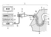
- FIG. 1 is a configuration diagram showing a first embodiment of an endoscope system as an insertion / extraction operation system according to the present invention.
- FIG. 2 is a configuration diagram illustrating a distal end portion of the insertion portion.
- FIG. 3A is a diagram illustrating a light transmission amount when the optical fiber sensor is bent to the side where the curved shape detection unit is provided.
- FIG. 3B is a diagram illustrating the light transmission amount when the optical fiber sensor is not bent.
- FIG. 3C is a diagram illustrating a light transmission amount when the optical fiber sensor is bent to the side opposite to the side where the curved shape detection unit is provided.
- FIG. 4 is a configuration diagram showing the support information unit.
- FIG. 1 is a configuration diagram showing a first embodiment of an endoscope system as an insertion / extraction operation system according to the present invention.
- FIG. 2 is a configuration diagram illustrating a distal end portion of the insertion portion.
- FIG. 3A is a diagram illustrating a light transmission amount
- FIG. 5 is a diagram illustrating the j-th and k-th detection-time insertion portion shapes corresponding to the j-th and k-th timing signals calculated by the detection-time insertion-portion shape calculation unit.
- FIG. 6 is a diagram illustrating an example of analysis for the shape change region.
- FIG. 7 is a diagram showing the shape change region KE1 when the jth operation unit side central axis Zja and the kth operation unit side central axis Zka in the shape change region shown in FIG. 6 are overlapped.
- FIG. 8 is a diagram illustrating changes in the shape of the endoscope insertion portion at the time of the j-th and k-th timing signals.
- FIG. 9 is a diagram illustrating an output image of the timing signal T as time elapses.
- FIG. 10 is a diagram illustrating a process of estimating the estimated shape information KE1h of the shape change region KE1 when the jth to hth timing signals T are generated.
- FIG. 11 is a diagram showing the entire insertion portion shape information (time change) Jh of the insertion portion 7 at the time of generation of the h-th timing signal estimated using the insertion portion shape time change information KA.
- FIG. 12 is a diagram showing each shape of the endoscope insertion portion when an operator's operation is added at the time point at which the j-th, k-th and h-th timing signals are generated.
- FIG. 10 is a diagram illustrating a process of estimating the estimated shape information KE1h of the shape change region KE1 when the jth to hth timing signals T are generated.
- FIG. 11 is a diagram showing the entire insertion portion shape information (time change) Jh of the insertion portion 7 at the time of generation of the h-th timing signal estimated using the insertion portion shape time change
- FIG. 13 shows an endoscope insertion section at the time of occurrence of each of the j-th and k-th timing signals acquired by the insertion section shape time change deriving section in the first modification of the first embodiment of the present invention. It is a figure which shows the shape of each shape change area
- FIG. 14 is a diagram illustrating a change in the connection direction of the shape change region of the endoscope insertion portion at each time point when the j-th and k-th timing signals are generated.
- FIG. 15 is a diagram illustrating insertion-side shape information at the time of detection for each of the jth and kth corresponding to each of the timing signals of jth and kth.
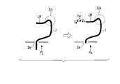
- FIG. 16 is a diagram for explaining three regions of the insertion portion shape dissimilar region NLR, the insertion portion progression region 7sr, and the insertion portion retraction region in the insertion portion.
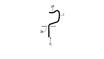
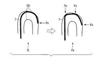
- FIG. 17A is a diagram illustrating a jth detection-time insertion portion shape Fj.
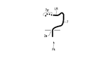
- FIG. 17B is a diagram illustrating a kth detection-time insertion portion shape Fk.
- FIG. 17C is a diagram illustrating the hth detection-time insertion portion shape Fh1 in a case where approximate information such as the shape of the internal space of the observation target is obtained.
- FIG. 17D is a diagram illustrating an h-th detection-time insertion portion shape Fh2 when there is no approximate information such as the shape of the internal space of the observation target.
- FIG. 17A is a diagram illustrating a jth detection-time insertion portion shape Fj.
- FIG. 17B is a diagram illustrating a kth detection-time insertion portion shape Fk.
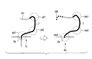
- FIG. 18 is a diagram illustrating examples of the first to third feature portions in the jth and kth detection-time insertion portion shapes Fj and Fk in the first modification example of the second embodiment of the invention.
- FIG. 19 is a configuration diagram showing a support information unit according to the third embodiment of the present invention.
- FIG. 20 is a diagram showing an inner surface profile of the internal space of the observation object corresponding to the jth and kth pieces of shape information Fj and Fk.
- FIG. 21 is a diagram for explaining the operation by the object inner surface profile information estimation unit.
- FIG. 22 is a diagram for explaining the operation by the object inner surface profile information estimation unit.
- FIG. 23 is a block diagram showing a support information unit in the first modification of the third embodiment of the present invention.
- FIG. 24 is a diagram for explaining the operation of the observation object load estimation unit.
- FIG. 25 is a diagram showing an example of a modification of the present invention.
- FIG. 1 shows a configuration diagram of an endoscope system 1 as an insertion / extraction operation system.
- an endoscope insertion portion (hereinafter referred to as an insertion portion) 7 is inserted into the interior space (cavity) 3 of the observation object 2 mainly by the work of the operator, and the observation object 2 It is used for observing the inner surface of the internal space 3.
- the system 1 includes an endoscope main body unit 4, an endoscope scope unit 5, and a display unit 6 as components.
- the endoscope scope unit 5 includes an insertion unit 7.
- a shape sensor 8 is mounted on the insertion portion 7.
- the endoscope scope unit 5 includes an insertion unit 7, an operation unit 9, and a main body side cable 10.
- the endoscope scope unit 5 is gripped and operated by an operator. By this operation, the insertion part 7 of the endoscope scope part 5 is moved to a position where it can be inserted from an insertion opening 2 a as an entrance part of the observation object 2, and further inserted into the internal space 3 of the observation object 2.
- the main body side cable 10 connects between the endoscope scope section 5 and the endoscope main body section 4 and is detachable from the endoscope main body section 4.
- One or a plurality of main body side cables 10 are connected between the endoscope scope section 5 and the endoscope main body section 4.
- the insertion part 7 will be specifically described.
- the insertion portion 7 is formed by a tip portion 7a and a portion other than the tip portion 7a.
- the distal end portion 7a includes a hard region (hard portion).
- the region other than the tip portion 7a is formed to have flexibility.
- the hard part of the tip part 7a is formed in a preset area (small area).
- a partial region on the distal end portion 7a side is formed in an active bending portion 7b that can be bent actively.
- the active bending portion 7b can be actively bent in the up-down direction and the left-right direction when the operator operates the operation handle 11 provided in the operation unit 9.
- a passive bending portion 7c that can be passively bent is formed in the region of the other insertion portion 7.
- the passive bending portion 7 c is passively bent by following the shape of the observation object 2.
- the passive bending portion 7c is passively bent depending on how the operator grips or the positional relationship between the insertion opening 2a of the observation object 2
- the operation unit 9 includes an operation handle 11.
- the operation handle 11 is operated by an operator to bend the active bending portion 7b of the insertion portion 7 in the vertical direction or the horizontal direction.
- the operation unit 9 is gripped by, for example, one hand of an operator, and the operation handle 11 is operated in this state, whereby the active bending unit 7b of the insertion unit 7 is bent in the vertical direction or the horizontal direction.
- the operation unit 9 can change the amount of bending of the active bending portion 7 b in the insertion portion 7 in response to an operation on the operation handle 11 by the operator.
- FIG. 2 is a configuration diagram of the distal end portion 7a of the insertion portion 7 in the system 1.
- Various members are provided at the distal end portion 7 a of the insertion portion 7 according to the use of the endoscope including the imaging element 7 d, the objective lens 10, the forceps channel 12, and the illumination unit 13.
- the objective lens 10 is optically connected to the image sensor 7d.
- the forceps channel 12 is an opening for inserting forceps and the like for performing various operations and treatments in the internal space 3 of the observation object 2.
- the illuminating unit 13 emits light emitted from the light source unit 20 of the endoscope main body unit 4 toward the internal space 3 of the observation object 2, for example.
- the present system when light emitted from the illumination unit 13 of the insertion unit 7 is irradiated on the internal space 3 of the observation object 2, light reflected from the internal space 3 of the observation object 2 is reflected on the objective lens 10. Is incident on.
- An image pickup device 7d is provided at the distal end portion 7a of the insertion portion 7. The image pickup device 7d picks up the light incident on the objective lens 10 and outputs an image pickup signal.
- This imaging signal is sent to the video processor 21 through the main body side cable 10.
- the video processor 21 obtains an observation image of the inner surface of the observation object 2 by performing image processing on the imaging signal output from the imaging element 7d. This observation image is displayed on the display unit 6.
- the insertion portion 7 includes an active bending portion 7b that is bent by the operation of the operation handle 11, and a passive bending portion 7c that is passively bent.
- the passive bending portion 7 c is bent so as to follow the shape of the wall surface of the internal space 3 by being pressed against the wall surface of the internal space 3 of the observation object 2.
- the internal space 3 of the observation object 2 includes introduction paths having various shapes depending on the type of the observation object 2 and the like.
- the insertion portion 7 has a structure capable of traveling inside the internal space 3 of the observation object 2.
- a shape sensor 8 for detecting the entire shape of the insertion portion 7 is provided inside the insertion portion 7.
- the shape sensor 8 is, for example, an optical fiber sensor (hereinafter described as the optical fiber sensor 8).
- the optical fiber sensor 8 is provided with a plurality of detection points so that the entire shape of the insertion portion 7 can be detected.
- These detection points include, for example, a light absorber (hereinafter referred to as a curved shape detection unit) 8b provided in an optical fiber 8a forming the optical fiber sensor 8 as shown in FIGS. 3A to 3C. These detection points are distributed in the longitudinal direction of the optical fiber sensor 8 over almost the entire length of the insertion portion 7. The configuration and principle of the optical fiber sensor 8 will be described later.
- the insertion part 7 and the operation part 9 are mechanically connected.
- the operation unit 9 and the main body side cable 10 are also mechanically connected.
- the endoscope main body 4 includes a light source unit 20, a video processor 21, a support information unit 22, and a main body memory 40.
- the light source unit 20 includes lamps such as xenon and halogen, or semiconductor light sources such as LEDs and lasers.
- a member capable of guiding light such as a light guide, is provided through the main body side cable 10, the operation unit 9, and the insertion unit 7. Thereby, when light is emitted from the light source unit 20, the light is emitted as illumination light from the illumination unit 13 provided at the distal end portion 7a of the insertion unit 7 via a light guide or the like. This illumination light is incident on the inside of the observation object 2 and illuminates the inside of the observation object 2.
- the video processor 21 obtains an observation image of the inner surface of the observation object 2 by performing image processing on the imaging signal output from the imaging element 7 d mounted on the distal end portion 7 a of the insertion portion 7.
- An image pickup signal output from the image pickup device 7 d is transmitted to the video processor 21 through a signal line provided in the insertion unit 7, the operation unit 9, and the main body side cable 10.
- the video processor 21 converts the acquired observation image into an observation image signal that can be displayed on the display unit 6 and sends the observation image signal to the display unit 6.
- the main body memory 40 information on the observation object 2 and information on observation work when observing the observation object 2 are stored in advance.
- the main body memory 40 stores the estimated shape information M output from the support information unit 22.
- FIG. 4 shows a configuration diagram of the support information unit 22.
- the support information unit 22 includes a part of the shape sensor unit 23.
- the shape sensor unit 23 includes an optical fiber sensor 8, a fiber sensor light source 24, and a photodetector 25.
- the fiber sensor light source 24 and the light detector 25 are included in the support information unit 22, and the optical fiber sensor 8 is not included in the support information unit 22.
- the shape sensor unit 23 outputs a detection signal D indicating optical information corresponding to the curved shape of the insertion portion 7. Details of the configuration and operation of the shape sensor unit 23 will be described later.
- the optical information corresponding to the curved shape of the insertion portion 7 represents the amount of light corresponding to the curved angle of the optical fiber disposed in the optical fiber sensor 8.
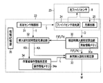
- the support information unit 22 functions as a work support unit that supports insertion / removal of the insertion unit 7 into / from the observation object 2. That is, the support information unit 22 receives the detection signal D output from the shape sensor unit 23 and processes the detection signal D to support the work and operation of the worker, that is, the insertion unit 7. Preliminary estimated shape information M obtained by estimating the shape is output.
- This support information unit 22 includes a detection insertion part shape calculation part (hereinafter referred to as a shape calculation part) 30, a shape sensor control part 31, and an insertion part shape time change derivation part (hereinafter referred to as a change derivation part) 32. And an insertion portion shape estimation unit (hereinafter referred to as a “foreign shape estimation unit”) 33, an operator operation information estimation unit (hereinafter referred to as an operation estimation unit) 34, and an information storage unit 35.
- a detection insertion part shape calculation part hereinafter referred to as a shape calculation part
- a shape sensor control part 31 a
- the shape sensor unit 23 includes a signal processing circuit (not shown) for processing the output signal of the photodetector 25 and outputting the detection signal D.
- the shape calculation unit 30 calculates the direction and size of the bending when the insertion unit 7 is bent by performing arithmetic processing on the detection signal D output from the shape sensor unit 23, and calculates the result of the calculation as the insertion portion shape at the time of detection. It outputs as information F (henceforth insertion part shape information) F.
- information F here, since the insertion portion 7 is formed to have flexibility except for the distal end portion 7a, the insertion portion 7 is often curved.
- the shape calculation unit 30 is described not as simply calculating the shape of the insertion portion 7 but as calculating the direction and magnitude of the bending when the insertion portion 7 is bent.
- the shape calculation unit 30 includes a curvature information memory 30a.
- the bending information memory 30 a stores information indicating the relationship between the bending angle of the insertion portion 7 and the change in optical information indicated by the detection signal D output from the shape sensor unit 23.
- the curvature information memory 30a stores information on the number of detection points of the optical fiber sensor 8, the arrangement positions of these detection points, and the directions of curvature (X direction and Y direction) detected at these detection points. Saved. Therefore, the shape calculation unit 30 determines the direction and magnitude of the bending when the insertion unit 7 is bent based on the detection signal D output from the shape sensor unit 23 and the information stored in the bending information memory 30a. And the calculation result is output as insertion portion shape information F.
- the shape sensor control unit 31 outputs a timing signal T for the timing at which the shape sensor unit 23 detects the curved shape of the insertion unit 7.
- the timing signal T is, for example, a rectangular wave that becomes a high level at a constant period.
- n is a natural number of 2 or more
- j and k are different natural numbers of n or less
- the magnitude relationship between j and k is j ⁇ k
- the shape sensor control unit 31 performs the first to nth timings.
- a rectangular-wave timing signal T that is at a high level is output.
- the first to nth timing signals T include a jth timing signal T and a kth timing signal T.
- the change deriving unit 32 receives the timing signal T output from the shape sensor control unit 31 and inserts shape information F (hereinafter referred to as jth) output from the shape calculation unit 30 when the jth timing signal T is generated. Insertion portion shape information Fj) and the insertion portion shape information F (hereinafter referred to as kth insertion portion shape information Fk) output from the shape calculation unit 30 when the kth timing signal T is generated. To do.
- the change deriving unit 32 compares the jth insertion unit shape information Fj received from the shape calculation unit 30 with the kth insertion unit shape information Fk. Note that the jth insertion portion shape information Fj also indicates the jth detection insertion portion shape for convenience. Similarly, the kth insertion portion shape information Fk also indicates the kth detection-time insertion portion shape for convenience.
- the change deriving unit 32 analyzes the shape change of the insertion unit 7 during the period from the generation of the jth timing signal T to the generation of the kth timing signal T based on the comparison result, and the analysis Is output as insertion portion shape time change information (hereinafter referred to as shape change information) KA. Details of the shape change information KA will be described later.
- the shape estimation unit 33 receives the insertion portion shape information F output from the shape calculation unit 30 and the shape change information KA output from the change derivation unit 32, and receives the insertion portion shape information F and the shape change information KA.
- the curved shape of the insertion portion 7 is estimated in advance from the current timing to the next timing, for example, from the current jth timing to the next kth timing.
- the shape estimation unit 33 outputs the estimated shape of the insertion portion 7 as the estimated shape information M.
- the shape estimation unit 33 receives the operator operation information L output from the operation estimation unit 34 together with the insertion unit shape information F and the shape change information KA.
- the shape estimation unit 33 estimates the shape of the insertion unit 7 based on information obtained by combining the insertion unit shape information F, the shape change information KA, and the operator operation information L, and outputs the shape as estimated shape information M. To do.
- the operation estimation unit 34 receives the shape change information KA output from the change derivation unit 32, and based on the shape change information KA, the operator determines the k-th timing signal T from the generation of the j-th timing signal T. The operator's operation performed during the period until the occurrence is estimated, and the estimated operator's operation is output as worker operation information L. The worker operation information L will be described later.
- the operation estimation unit 34 includes an operation information memory 34a in which handle operation information indicating the position of the shape change of the insertion unit 7 when the operation handle 11 is operated, a curved shape, and the like is stored.
- the information storage unit 35 includes a detection signal D output from the shape sensor unit 23, various types of information transmitted in the support information unit 22, such as insertion portion shape information F, shape change information KA, and operator operation information. L and the estimated shape information M are stored in association with the timing signal T.
- the information storage unit 35 includes a plurality of detection points provided in the optical fiber sensor 8, that is, position information of the light absorber 8 a, a light amount corresponding to the bending angle of the insertion unit 7 and the bending angle of the optical fiber sensor 8. Correspondence information with the detection signal D indicating is stored.
- the information storage unit 35 passes through a path (not shown) among the shape calculation unit 30, the shape sensor control unit 31, the change derivation unit 32, the shape estimation unit 33, and the operation estimation unit 34 in the support information unit 22. Information can be exchanged. Information stored in the information storage unit 35 can be read as appropriate by the operator. The information storage unit 35, each main body memory 40, the bending information memory 30a, and the operation information memory 34a can use the storage areas of the same memory device in association with each other. Further, the common information is stored in any one of the main body memory 40, the bending information memory 30a, the operation information memory 34a, or the information storage unit 35, and the main body memory 40, the bending information memory through a path (not shown). 30a, the operation information memory 34a, or the information storage unit 35 can be made readable.
- the endoscope main body 4 may include a printer, for example.
- the endoscope main body 4 may include all of medical devices necessary for various treatments and treatments, and all of those that can be connected to the endoscope system 1.
- the light source unit 20, the video processor 21, and the support information unit 22 function separately within the endoscope body unit 4, but are not limited thereto.
- the light source unit 20, the video processor 21, and the support information unit 22 may function as one processing unit inside the endoscope body unit 4. Some functions of the light source unit 20 and the video processor 21 may be incorporated in the support information unit 22.
- the endoscope body 4 can be integrated with units other than the three units of the light source 20, the video processor 21, and the support information unit 22.
- the endoscope main body 4 can be freely combined in consideration of various circumstances such as user convenience, ease of design, and cost, such as combining with another unit.
- the support information unit 22 configures the functions of the shape calculation unit 30, the shape sensor control unit 31, the change derivation unit 32, the shape estimation unit 33, and the operation estimation unit 34 as one processing unit. It is possible. On the other hand, the support information unit 22 has the functions of the shape calculation unit 30, the shape sensor control unit 31, the change derivation unit 32, the shape estimation unit 33, and the operation estimation unit 34 as independent units. It is also possible to configure.
- the support information unit 22 can be freely combined in consideration of various circumstances such as user convenience, ease of design, and cost, such as combining with another unit.
- the display unit 6 displays the internal space 3 of the observation object 2 to be observed by the system 1, information on the observation object 2 stored in advance in the main body memory 40 of the endoscope main body 4, and the observation object 2. Information of observation work at the time of observation and estimated shape information M output from the support information unit 22 can be displayed.
- the display unit 6 includes a monitor display made of, for example, a liquid crystal, a cathode ray tube, an LED, or plasma. Although the number of the display units 6 is one for convenience in FIG. 1, the display unit 6 is not limited thereto, and two or more display units 6 may be arranged side by side, or a plurality of units may be arranged in different places.
- the display unit 6 is not limited to displaying images and text information on a monitor display.
- the display unit 6 includes a variety of information for informing the operator of information, including an output for recognizing by auditory sense such as voice or alarm sound, and an output for recognizing by tactile sense such as vibration.
- Output devices based on the transmission method are collectively referred to as a display unit.
- the optical fiber sensor (shape sensor) 8 is provided with a curved shape detector 8b on a part of the side surface of the long optical fiber 8a.
- the optical fiber sensor 8 used in the present embodiment utilizes a phenomenon in which the amount of light absorbed by the curved shape detection unit 8b increases or decreases according to the bending angle of the optical fiber 8a.
- the amount of light transmitted through the optical fiber 8a decreases in the optical fiber sensor 8, for example, when the amount of light absorbed by the curved shape detection unit 8b increases according to the bending angle of the optical fiber 8a. Therefore, the optical fiber sensor 8 emits an optical signal having a light amount corresponding to the bending angle of the optical fiber 8a.
- the optical fiber sensor 8 is composed of, for example, the optical fiber 8a. Therefore, when the insertion portion 7 is bent, the optical fiber 8a is bent in accordance with the bending, and the light transmitted through the optical fiber 8a is accordingly transmitted. A part of the light leaks to the outside through the curved shape detection unit 8b or is absorbed by the curved shape detection unit 8b, so that the amount of light passing through the optical fiber sensor 8 decreases.
- the curved shape detection unit 8b has a configuration in which a part of the clad of the optical fiber 8a is removed and a light absorbing member or a dye is applied to the part from which the clad is removed.
- the curved shape detection unit 8b is provided on one side surface of the optical fiber 8a, and reduces a part of the light transmitted according to the curvature of the optical fiber 8a. That is, the curved shape detection unit 8b changes the optical characteristics of the optical fiber 8a, for example, the amount of light transmission, according to the curvature of the optical fiber 8a.
- FIG. 3A shows the light transmission amount when the optical fiber 8a is bent to the side where the curved shape detector 8b is provided
- FIG. 3B shows the light transmission amount when the optical fiber 8a is not bent
- FIG. 3C shows the optical fiber. It is an image figure which shows the light transmission amount when 8a curves to the opposite side to the side in which the curved shape detection part 8b was provided.
- the optical transmission amount when the optical fiber 8a is bent to the side where the curved shape detecting unit 8b is provided is the largest, the optical transmission amount when the optical fiber 8a is not bent next, and then the optical fiber.
- the light transmission amount decreases in the order of the light transmission amount when 8a is bent to the side opposite to the side on which the curved shape detection unit 8b is provided.
- the optical fiber sensor 8 becomes a bending sensor by providing one curved shape detection unit 8b.
- the optical fiber sensor 8 can detect the entire three-dimensional shape of the insertion portion 7 by providing a plurality of curved shape detection portions 8 b in the longitudinal direction and the circumferential direction of the insertion portion 7.
- the optical fiber sensor 8 may include optical means such as attaching a pigment to the curved shape detection unit 8b and separating light according to wavelength. Thereby, the optical fiber sensor 8 can provide the some curved shape detection part 8b in one optical fiber. If a plurality of optical fibers provided with the curved shape detector 8b are bundled, it is possible to detect the bending angle at a plurality of points. If the number of curved shape detectors 8b provided per optical fiber is increased, the number of optical fibers 8a can be reduced.
- the optical fiber sensor 8 is mounted on the insertion portion 7 so that a plurality of curved shape detection portions 8b are provided at a predetermined interval, for example, every 10 cm. If the plurality of curved shape detection units 8b are provided at such intervals, the entire curved shape of the insertion unit 7 can be detected with high accuracy. If the interval between the curved shape detection units 8b is longer than, for example, 10 cm, the number of the curved shape detection units 8b can be reduced to reduce the cost and simplify the system configuration for detecting the curved shape.
- the insertion portion 7 can be bent in an arbitrary direction by an operator, for example.
- two or more curved shape detection portions 8b may be provided in different circumferential directions at substantially the same location of the insertion portion 7.
- the shape sensor unit 23 includes a function of detecting a change in the amount of light guided to the optical fiber sensor 8, and includes a fiber sensor light source 24 and a photodetector 25.
- the optical fiber sensor 8 is provided in the insertion portion 7.
- the fiber sensor light source 24 and the photodetector 25 are provided in the support information unit 22.
- the fiber sensor light source 24 emits detection light.
- the detection light emitted from the fiber sensor light source 24 enters the optical fiber sensor 8, is guided by the optical fiber sensor 8, and enters the photodetector 25.
- the detection light passes through the curved shape detection unit 8 b provided in the optical fiber sensor 8.
- the photodetector 25 detects incident light, converts the detected light amount into a detection signal D by a signal processing circuit (not shown), and outputs the detection signal D.
- This detection signal D is transmitted to the shape calculation unit 30.
- the photodetector 25 detects incident light separately by wavelength, converts the spectral light amount of the detected light into a detection signal D by a signal processing circuit (not shown), and outputs it. .
- the shape sensor control unit 31 When the shape sensor control unit 31 recognizes that the shape sensor unit 23 is in a detectable state by receiving the detectable signal, the shape sensor control unit 31 sequentially outputs the first to n-th timing signals T.
- the first high-level signal is the first timing signal
- the generation intervals of the first to n-th timing signals T can be set as appropriate depending on the content of the target support information, the request from the operator, the operation speed of the support information unit 22 and the shape sensor unit 23, and the like.
- the first to nth timing signals T may be periodic at regular intervals, or the intervals of the first to nth timing signals may be changed depending on the situation.
- the shape sensor unit 23 receives the first to n-th timing signals T output from the shape sensor control unit 31.
- the photodetector 25 detects the optical signal output from the optical fiber sensor 8 according to the first to n-th timing signals T, passes through the curved shape detection unit 8b, and detects the detection signal D corresponding to the optical signal. Is output.
- the optical fiber sensor 8 itself a known one can be used, and the description thereof is omitted.
- the shape sensor unit 23 turns on the fiber sensor light source 24 when the power is turned on.
- the fiber sensor light source 24 emits detection light that continuously emits light with basically the same brightness and spectrum. This detection light is incident on the incident end of the optical fiber 8 a of the optical fiber sensor 8.
- the optical fiber sensor 8 guides the detection light incident from the incident end of the optical fiber 8 a, and the detection light is emitted from the optical fiber 8 a via the curved shape detection unit 8 b provided in the optical fiber sensor 8. Inject from the end.
- the light emitted from the exit end of the optical fiber 8 a enters the photodetector 25.
- the optical fiber sensor 8 when the optical fiber sensor 8 is bent together with the insertion portion 7, the amount of light absorbed by the curved shape detection portion 8b changes according to the bending angle. For example, as shown in FIG. 3A, the amount of light absorbed by the curved shape detection unit 8b decreases as the bending angle of the optical fiber 8a increases toward the curved shape detection unit 8b. Thereby, the light quantity which permeate
- the optical fiber sensor 8 outputs an optical signal having a light amount corresponding to the bending angle of the insertion portion 7.
- the optical signal output from the optical fiber sensor 8 enters the photodetector 25.
- the photodetector 25 receives the incident optical signal, converts it into an electrical signal, and outputs the electrical signal as a detection signal D corresponding to the light amount of the optical signal by a signal processing circuit.
- the shape sensor unit 23 associates each optical signal emitted from the plurality of curved shape detectors 8b provided in the optical fiber sensor 8 with the first to n-th timing signals T, and a plurality of curved shape detectors. A flag is attached to the detection signal D so that each optical signal emitted from 8b can be identified. This detection signal D is sent to the shape calculation unit 30.
- the shape calculating unit 30 receives the detection signal D with a flag output from the shape sensor unit 23, detects the position information of the curved shape detecting unit 8b stored in the information storage unit 35, the bending angle of the optical fiber, and the detection.
- the bending angle light quantity information indicating the relationship with the signal D (light quantity)
- the direction and magnitude of the bending when the insertion section 7 is curved for each of the first to n-th timing signals T are calculated, and the insertion section Output as shape information F.
- the shape calculation unit 30 calculates the jth insertion portion shape information Fj based on the detection signal D associated with, for example, the jth timing signal Tj among the first to nth timing signals T1 to Tn. .
- the shape calculation unit 30 sequentially outputs k-th, l-th,..., N-th (k-th to n-th) timing signals Tk, Tl,.
- the detection signal D sequentially output from the shape sensor unit 23 is received every time, and the kth to nth insertion portion shape information Fk to Fn is calculated for each of the kth to nth timing signals T.
- the kth to nth insertion portion shape information Fk to Fn are sequentially stored in the information storage unit 35 in the support information unit 22.
- the change deriving unit 32 receives at least two insertion unit shape information F output from the shape calculation unit 30 based on the first to n-th timing signals T1 to Tn, and receives the insertion unit shape information F.
- the shape change information KA is derived by comparison.
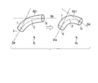
- the change deriving unit 32 compares the jth insertion portion shape information Fj calculated by the shape calculation unit 30 as shown in FIG. 5 with the kth insertion portion shape information Fk.
- the change deriving unit 32 extracts a region where the bending shape of the insertion unit 7 is changed as the shape change region KE1, and the region where the bending shape of the insertion unit 7 is not changed is the first and second shapes. Extracted as unchanged regions KE2a and KE2b.
- the curved shape of the insertion portion 7 is not changed, but the relative positional relationship between the first and second shape-invariant regions KE2a and KE2b. Has changed. This relative positional relationship is because the shape of the shape change region KE1 in the insertion portion 7 has changed.
- the change deriving unit 32 calculates the classification of the type of change in the curved shape of the extracted shape change region KE1 and the amount of change in the curved shape in the shape change region KE1.
- the insertion portion 7 is formed in an elongated rod shape having a substantially circular cross section and having flexibility.
- the partial change in the curved shape of the insertion portion 7 includes, for example, two changes in the shape of the curve and the twist. Further, as the partial change in the curved shape of the insertion portion 7, there can be considered a case where the bending and twisting occur in combination, or a case where the bending and twisting occur continuously in each adjacent region. .
- FIG. 6 shows an example of analysis for the shape change region KE1, and an example of analysis for the shape change region KE1 when the j-th timing signal Tj is generated and the shape change region when the k-th timing signal Tk is generated.
- An example of analysis for KE1 is shown.
- the change deriving unit 32 compares the curved shapes of the shape change region KE1 when two timing signals are generated, for example, when each of the j-th timing signal Tj and the k-th timing signal Tk is generated. Since the jth and kth insertion portion shape information Fj and Fk are three-dimensional information, the shape information of the shape change region KE1 is also three-dimensional information.
- the change deriving unit 32 is based on the jth and kth insertion portion shape information Fj, Fk, in the axial directions of both ends of the shape change region KE1, that is, both ends of the jth insertion portion shape Fj.
- the axial directions Zja and Zjb of the portion and the axial directions Zka and Zkb of both ends of the kth insertion portion shape Fk are set.
- Zja is the j-th operation unit side central axis
- Zjb is the j-th tip side central axis.
- Zka is the k-th operation unit side central axis Zka
- Zkb is the k-th tip side central axis.
- Z is the central axis of the insertion portion 7 in the shape change region KE1.
- the operation unit 9 side closest to the operation unit 9 is connected to the shape non-change region KE2 or directly connected to the operation unit 9. In the present embodiment, it is connected to the first shape invariable region KE2a. Therefore, the type of change in the curved shape, the amount of change in the curved shape, and the direction of the curved change in the shape change region KE1 are as follows.
- the jth operation unit side central axis Zja and the kth operation unit side are shown in FIG. It is calculated from the positional relationship between the j-th tip-side center axis Zjb and the k-th tip-side center axis Zkb when the center axes Zka are overlapped with each other.
- the shape change region KE1 is bent by an angle ⁇ (hereinafter referred to as a bending angle) ⁇ around a portion where the j-th and k-th operation unit side central axes Zja and Zka are overlapped.
- This angle ⁇ is the amount of change in bending when the insertion portion 7 is bent during the period from the j-th to the k-th timing signal T.
- the j-th and k-th tip side central axes Zjb and Zkb change only in the same plane, it can be understood that the insertion portion 7 is simply curved without being twisted.
- the change amount and the direction of the shape change region KE1 can be calculated as the change amount and the direction of the bending angle.
- the type of change is a change in the bending angle.
- the amount of change in the bending angle is the size of the angle formed by the j-th and k-th tip side center axes Zjb and Zkb, that is, the angle ⁇ as shown in FIG.
- the bending direction is a moving direction (clockwise direction) from the jth tip side center axis Zjb to the kth tip side center axis Zkb indicated by an arrow in the drawing.
- the change deriving unit 32 outputs the change amount (angle ⁇ ) of the bending angle of the insertion unit 7 and information on the direction (clockwise direction) as the shape change information KA.
- the type of change is in-plane curvature
- the amount of change is an angle ⁇
- the direction of change is clockwise.
- the shape change information KA is sent to the shape estimation unit 33 and the operation estimation unit 34, respectively.
- the operation estimation unit 34 estimates an operation performed by the worker, and outputs the estimated operation of the worker as worker operation information L.
- the operation estimating unit 34 assumes that the change in the curved shape of the insertion unit 7 is a result of the operator's operation, and based on the shape change information KA, for example, the jth timing signal Tj and the kth timing.
- the operator's operation performed during the period with the signal Tk is estimated, and the estimated operator's operation is output as worker operation information L.
- the type of operation by the operator, the direction of the operation, and the operation amount are estimated. That is, the worker operation information includes the type of operation by the worker, the direction of the operation, and the operation amount.
- the operator's operation is roughly classified into two types, that is, an operation handle operation for operating the operation handle 11 and a direct operation for directly gripping and operating the insertion portion 7.
- the operation handle operation is to operate the operation handle 11 to bend the active bending portion 7b of the insertion portion 7.
- the direct operation the operator directly grips and pushes the part of the insertion portion 7 that is not inserted into the internal space 3 of the observation object 2 (the part protruding from the internal space 3 of the observation object 2), pulls out, Or operations such as twisting are performed.
- the operation direction when the operator operates the operation handle 11 and the bending angle and the bending direction of the insertion unit 7 according to the operation amount are determined for each type of the endoscope scope unit 5 as handle operation information.
- the operation directions are, for example, the vertical direction and the horizontal direction.
- the operation amount is an operation amount in the up / down direction and an operation amount in the left / right direction.
- Such handle operation information is stored, for example, in an operation information memory 34 a provided in the operation estimation unit 34.
- the curved portion is the active bending portion 7 b and that the change in the bending shape of the active bending portion 7 b is due to the operator's operation on the operation handle 11. That is, the assumed change in the curved shape of the active bending portion 7b may coincide with the change in the curved shape of the active bending portion 7b that is actually operated. In this case, it is possible to determine that the bending change of the active bending portion 7 b is due to the operator's operation on the operation handle 11.
- the operation estimation unit 34 estimates that the operation is a direct operation by the worker, or a combined operation in which both the direct operation by the worker and the operation on the operation handle 11 are combined.
- the operation by the worker is determined to be a direct operation.
- the direct operation is performed by directly gripping the operation unit 9 or the portion of the insertion unit 7 protruding from the internal space 3 of the observation object 2, the operation force by the operator is on the operation unit 9 side in the shape change region KE1.
- the operation estimation unit 34 estimates the operator's operation on the assumption that an operation by a worker who can cause a change in the curved shape of the shape change region KE1 is applied from the operation unit 9 side.
- the operation estimating unit 34 If there is no deformation in the shapes of the first and second shape invariable areas KE2a and KE2b, the operation estimating unit 34 considers that there is no deformation, and the change in the curved shape of the shape changing area KE1 is performed by the operator. It is estimated that
- the shape of the first shape invariant region KE2a is not deformed during the period from the jth to the kth timing signal T.
- the force by the operator's operation may be an operation that transmits the operation force to the end of the shape change region KE1 on the operation unit 9 side without changing the shape of the first shape invariable region KE2a. I understand.
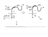
- the operation estimation unit 34 can estimate that an operation Q that pushes the insertion unit 7 in the axial direction of the insertion unit 7 from the operation unit 9 side as shown in FIG. FIG. 8 shows the jth insertion portion shape information Fj and the kth insertion portion shape information Fk operated by the operator. Further, the operation estimation unit 34 is the amount of operation performed by the operator based on the information on the hardness of the observation object 2 stored in the information storage unit 35 and the force required for bending based on the structure of the insertion unit 7. Estimate the approximate value of. Structural information related to the structure of the insertion unit 7 is stored in, for example, the information storage unit 35. This structure information includes information such as the ease of bending partially or in each bending direction based on the structure of the insertion portion 7, the ease of maintaining the shape of the insertion portion 7, and the force required to bend the insertion portion 7. including.
- the operation estimation unit 34 refers to the structure information of the insertion unit 7 stored in the information storage unit 35 and other information such as the physical property information and shape information of the observation object 2.
- the operation estimation unit 34 determines the type of operation performed by the worker, The operation amount of the operation is defined as the type of operation performed by the worker, the direction of the operation, and the operation amount of the operation during the period of the j-th timing signal Tj and the k-th timing signal Tk.
- L is output to the shape estimation unit 33.
- the type of operation performed by the operator includes, for example, pushing the observation object 2 of the insertion unit 7 into the internal space 3.
- the operation direction includes the direction of the central axis of the portion of the insertion portion 7 that protrudes outside the internal space 3 of the observation object 2 from the insertion opening 2a as shown in FIG.
- the manipulated variable is estimated from the positional relationship between the first and second shape invariant regions KE2a and KE2b when the jth timing signal Tj and the kth timing signal Tk are generated.
- the operation estimation unit 34 uses the shape change amount ⁇ Pj in the direction of the operation Q of the shape change area KE1 in the jth insert portion shape information Fj and the kth insert portion shape information Fk.
- the shape change amount ⁇ Pj in the j-th insertion portion shape information Fj in the present embodiment is the central axis direction (vertical direction in the drawing) of the insertion portion 7 protruding outside the observation object 2 from the insertion opening 2a.
- the shape change amount ⁇ Pk in the k-th insertion portion shape information Fk similarly represents a change in the central axis direction (vertical direction in the drawing) of the insertion portion 7 that is exposed to the outside of the observation object 2 from the insertion opening 2a.
- the shape estimation unit 33 receives the insertion portion shape information F (including Fj and Fk) output from the shape calculation unit 30 and receives the shape change information KA output from the change derivation unit 32 or the operation estimation unit 34. One or both of the operator operation information L to be output is received.
- the shape estimation unit 33 calculates the estimated shape information M based on the insertion portion shape information F and either one or both of the shape change information KA and the worker operation information L.
- the portion where the curved shape is deformed in the insertion portion 7 is a shape change region KE1 in which both ends are sandwiched between the first shape unchanged region KE2a and the second shape unchanged region KE2b.
- the change deriving unit 32 outputs the amount of change in the bending angle and the bending direction (clockwise direction) in the shape change region KE1 of the insertion unit 7 as the shape change information KA as shown in FIG.
- the shape estimation unit 33 receives the shape change information KA output from the change derivation unit 32, and the amount of change in the bending angle and the bending direction (clockwise direction) of the shape change region of the insertion unit 7 as the shape change information KA. ) To estimate the insertion portion shape information M.
- FIG. 9 shows an image of the timing signal T (T1, Tj, Tk, Th, Tn) according to past, present, and future time passages.
- h is a natural number larger than k.
- the shape sensor control unit 31 has already output the j-th and k-th timing signals Tj and Tk, and intends to output the h-th timing signal Th in the future.
- the time interval Tjk between the j-th and k-th timing signals Tj and Tk is equal to the time interval Tkh between the k-th and h-th timing signals Tk and Th.
- the operation type is a bending operation according to the shape change information KA
- the operation direction is a clockwise direction
- the operation amount is the j-th and k-th timing signals Tj.
- An angle ⁇ that is a bending angle during the period of Tk.
- the shape estimation unit 33 is information on the shape of the insertion portion when the h-th timing signal Th is generated based on the bending angle as the type of operation, the clockwise direction as the operation direction, and the angle ⁇ as the operation amount.
- FIG. 10 shows a process of estimating the estimated shape information KE1h of the shape change region KE1 when the jth to hth timing signals Tj to Th are generated.
- the figure shows the detected shape KE1j of the shape change region KE1 when the jth timing signal Tj is generated, the detected shape KE1k of the shape change region KE1 when the kth timing signal Tk is generated, and the hth timing signal Th.
- the shape estimation area information KE1h of the shape change area KE1 at the time of occurrence of the error is shown.
- the shape change region KE1 is estimated as the curve angle continuously changing at a constant change speed.
- FIG. 11 shows the insertion portion shape information (time change) Mh of the entire insertion portion 7 when the h-th timing signal Th is generated.
- the insertion portion shape information Mh includes the estimated shape information KE1h of the shape change region KE1 and the first and second shape invariant regions KE2a and KE2b on both ends of the shape change region KE1.
- FIG. 12 shows changes in each shape of the insertion portion 7 when the j, k, h timing signals Tj, Tk, Th are generated when the operator's operation is applied. That is, changes in the jth insertion portion shape information Fj, the kth insertion portion shape information Fk, and the hth insertion portion shape information Fh are shown.
- the worker operation information L is, for example, the type of operation pushed in and the direction of operation is output from the insertion opening 2a to the outside of the observation object 2 as described in the above section [Operation of the worker operation information estimation unit].
- the direction of the center of the insertion portion 7 is the operation amount, and the operation amount is an operation change amount ⁇ Pjk due to the operation of the operator.
- the shape estimation unit 33 estimates the shape of the insertion unit 7 when the future h-th timing signal Th is generated based on the operator operation information L.
- the estimation method is almost the same as the calculation of the estimated shape information M based on the insertion portion shape information F and the shape change information KA described above.
- the shape estimation portion 33 determines the curved shape of the insertion portion 7 when the operation type, the operation direction, and the operation amount are continuously estimated. Calculate as At the same time, the shape estimation unit 33 assumes that the shape change region KE1 is curved by the estimated operator's operation and that the shapes of the first and second shape invariant regions KE2a and KE2b do not change. The insertion portion shape information M is estimated.
- the time interval Tjk between the j-th and k-th timing signals Tj, Tk is equal to the time interval Tkh between the k-th and h-th timing signals Tk, Th.
- the operation change amount when the j-th timing signal Tj is generated is ⁇ Pjk
- the shape change amount when the k-th timing signal Tk is generated is ⁇ Pk
- the shape estimation unit 33 uses the operator operation information L estimated by the operation estimation unit 34 as shown in FIG. 12, and the shape deformation amount ⁇ Ph in the shape deformation region KE1 of the insertion unit 7 is expressed by the above equation (1).
- the deformation shape in the shape change region KE1 is estimated so as to be the shape change amount ⁇ Ph shown.
- the endoscope structure is considered in the estimation of the deformed shape of the shape change region KE1.
- the shape estimation unit 33 compares the insertion portion shape information (time change) M with the insertion portion shape information (operator operation) M to estimate the final insertion portion shape information M.
- the method for estimating the final insert portion shape information M from the two insert portion shape information M that is, the insert portion shape information (time change) M and the insert portion shape information (operator operation) M.
- the insert portion shape information M time change
- the insert portion shape information (operator operation) M there are several.
- a method for obtaining an average of the two insertion portion shape information M is also suitable. In this case, it is also preferable to simply obtain an average, and it is also preferable to take a weighted average in view of the other information described above. Further, it is also preferable to present both of the two insertion portion shape information M to the operator.
- the time interval Tjk between the j-th and k-th timing signals Tj, Tk and the time interval Tkh between the k-th and h-th timing signals Tk, Th are equal.
- the shape estimation unit 33 determines that the deformation in the shape deformation region KE1 of the insertion unit 7 and the operation by the worker are performed at a constant speed during the period of the jth and kth timing signals Tj and Tk.
- the insertion portion shape information M is estimated with the amount of change ⁇ of the bending angle of the insertion portion 7 as ⁇ / 2 and the operation amount as ⁇ Pjk / 2. do it.
- the insertion portion shape information M can be estimated by obtaining the elapsed time ratio.
- the shape of the insertion portion 7 inserted into the internal space 3 of the observation object 2 is detected by the shape sensor unit 23, and based on the detected insertion portion shape information F.
- the shape of the insertion portion 7 after the elapsed time Tkh from the k-th timing signal Tk to the h-th timing signal Th is estimated in advance and output as the estimated shape information M, the operator observes the insertion portion 7.
- the shape of the insertion part 7 which will be formed from now on can be estimated beforehand.
- the estimated shape of the insertion unit 7 can be displayed on the display unit 6 or the like as support information when the insertion unit 7 is inserted.
- the time required for training and skill improvement can be shortened as compared with the conventional endoscope system. Even an operator with a low experience and skill level can insert and remove the insertion portion 7 into and from the internal space 3 of the observation object 2 relatively easily.
- the worker can determine that the insertion / removal operation of the insertion portion 7 may proceed.
- the operator can determine that it is better to change the insertion / removal operation.
- the change deriving unit 32 shows an example of comparing two insertion portion shape information F, that is, the jth insertion portion shape information Fj and the kth insertion portion shape information Fk. However, it is not limited to this.
- the change deriving unit 32 can also compare three or more insertion portion shape information F. For example, j-th insertion portion shape information Fj, k-th insertion portion shape information Fk, and first insertion portion shape information Fl corresponding to the first timing signal T.
- the change in the shape of the insertion portion 7 It is possible to obtain information on the state, that is, whether it is changing stably at a low speed, whether it is changing with acceleration, or whether a repetitive operation is being performed.
- the operation estimation unit 34 can estimate the worker operation information L in consideration of using such three or more insertion portion shape information F (Fj, Fk, F1, etc.). Accordingly, the shape estimation unit 33 can estimate the insertion portion shape information M with higher accuracy.
- the operation of the change deriving unit 32 is different from that of the first embodiment.
- the change deriving unit 32 compares the jth insertion portion shape information Fj calculated by the shape calculation unit 30 as shown in FIG. 5 with the kth insertion portion shape information Fk. Based on the result of this comparison, the region where the shape of the insertion portion 7 is changed is extracted as the shape change region KE1, and the region where the shape of the insertion portion 7 is not changed is the first and second shapes. Extracted as change areas KE2a and KE2b.
- the change deriving unit 32 pays attention to the first and second shape invariant regions KE2a and KE2b extracted as regions in which the curved shape of the insertion unit 7 has not changed, and these shape invariants.
- the shape change information KA is derived based on the relative positional relationship between the change areas KE2a and KE2b.
- the operation of calculating the insertion portion shape information F by the shape calculation unit 30 and the operation of extracting the shape change region KE1 and the first and second shape invariant regions KE2a and KE2b by the change derivation unit 32 This is the same as in the first embodiment.
- FIG. 13 is a diagram for explaining the operation of the change deriving unit 32.
- the figure shows the shape of the insertion section 7 when the j-th timing signal Tj acquired by the change deriving section 32 is generated, and the insertion section when the k-th timing signal Tk acquired by the change deriving section 32 is generated. 7 shows the shape.
- the change deriving unit 32 compares the jth insertion unit shape information Fj calculated by the detection unit insertion unit shape calculation unit 30 with the kth insertion unit shape information Fk, and the shape is changed in the insertion unit 7.
- Shape change region KE1 and first and second shape invariant regions KE2a and KE2b whose shape has not changed in the insertion portion 7 are extracted.
- the insertion portion 7 includes a first connecting portion C1 connecting the first shape invariable region KE2a and the shape changing region KE1, and the shape changing region KE1 and the second shape invariant.
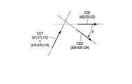
- the change deriving unit 32 includes the coordinates (connection unit coordinates) of the first connection unit C1 at the generation time point of the j-th timing signal Tj and the generation time point of the k-th timing signal Tk, and the first connection unit C1.
- the connection direction CD1 which is the tangential direction of the central axis of the insertion portion 7 at, is calculated.
- the change deriving unit 32 determines the coordinates of the second connection unit C2 (connection unit coordinates) at the generation time point of the j-th timing signal Tj and the generation time point of the k-th timing signal Tk, and the second connection.
- a connection direction CD2 that is a tangential direction of the central axis of the insertion portion 7 in the portion C2 is calculated.
- the coordinate system representing the connection portion coordinates of the first and second connection portions C1 and C2 can be compared with the jth insertion portion shape information Fj and the kth insertion portion shape information Fk. Any coordinate system may be used.
- the support information unit 22 sets the position of the jth insertion portion shape information Fj and the kth insertion portion shape information Fk closest to the operation unit 9 as the origin coordinates (0, 0, 0). That is, the origin coordinates (0, 0, 0) are located at the end of the first shape invariable region KE2a on the operation unit 9 side. In this modification, the support information unit 22 performs the first connection based on the origin coordinates (0, 0, 0), the jth insertion portion shape information Fj, and the kth insertion portion shape information Fk. The coordinates of the connection part coordinates of the part C1 and the connection part coordinates of the second connection part C2 are calculated.
- connection portion coordinates C1 on the front end side of the first shape invariable region KE2a at the time when the jth timing signal Tj is generated are represented by (x1j, y1j, z1j) as shown in FIG.
- the connecting portion coordinates C1 on the front end side of the first shape invariant region KE2a at the time of generation of the kth timing signal Tk are represented by (x1k, y1k, z1k).
- connection portion coordinates C1 (x1j, y1j , Z1j) and the connecting portion coordinates C1 (x1k, y1k, z1k) are equal.
- connection direction CD1 is calculated as a vector indicating the connection direction between the first shape invariant region KE2a and the shape change region KE1.
- connection direction CD2 is calculated as a vector indicating the connection direction between the shape change region KE1 and the second shape non-change region KE2b.
- each vector in each connection direction CD1, CD2 is obtained as a unit vector of length “1”.
- the vector of the connection direction CD1 at the time of generation of the j-th timing signal Tj is represented by (a1j, b1j, c1j) as shown in FIG.
- the vector of the connection direction CD2 at the time when the k-th timing signal Tk is generated is represented by (a1k, b1k, c1k). Since it is the first shape invariable region KE2a that is connected to the origin coordinates (0, 0, 0), in the first modification, the vector (1) of the connection direction CD1 at the time when the j-th timing signal Tj is generated. a1j, b1j, c1j) and the vector (a1k, b1k, c1k) of the connection direction CD1 at the time of generation of the k-th timing signal Tk.
- the coordinates of the second shape-invariant region KE2b at the time when the j-th and k-th timing signals Tj and Tk are generated are also obtained in the same manner as the coordinates of the first shape-invariant region KE2a.
- the connection point coordinates C2 on the base end side of the second shape invariable region KE2b at the time when the j-th timing signal Tj is generated are represented by (x2j, y2j, z2j) as shown in FIG.
- the connection portion coordinates C2 on the base end side of the second shape non-change region KE2b at the time when the k-th timing signal Tk is generated are represented by (x2k, y2k, z2k).
- the vector of the connection direction CD1 at the time when the j-th timing signal Tj is generated is represented by (a2j, b2j, c2j).
- the vector of the connection direction CD2 at the time when the k-th timing signal Tk is generated is represented by (a2k, b2k, c2k).
- the change deriving unit 32 can represent the information on the shape change of the insertion unit 7 by the positions and directions of the first and second shape invariant regions KE2a and KE2b. That is, the shape change region KE1 exists between the first and second shape non-change regions KE2a and KE2b.
- the information on the shape change of the insertion portion 7 includes the coordinates (x1j, y1j, z1j) of the first connecting portion C1 between the first shape invariant region KE2a and the shape change region KE1, and the second shape invariant region KE2b. And the coordinates (x2j, y2j, z2j) of the second connection portion C2 between the shape change region KE1 and the information of the vectors CD1 and CD2 in the tangential direction of the insertion portion 7 at these coordinates.
- FIG. 13 is described for the purpose of making it easy to imagine the shape change of the insertion portion 7.
- the first and second shape invariant regions KE2a and KE2b are represented by dotted quadrilaterals
- the shape changing region KE1 is represented by a solid line corresponding to the curved shape.
- the change deriving unit 32 does not need to generate information to be represented by dotted quadrilaterals and solid lines or use the information.
- the shape change region KE1 exists between the first and second shape non-change regions KE2a and KE2b is shown.
- the shape change region KE1 and the first or second shape non-change regions KE2a and KE2b may be alternately and repeatedly arranged.
- the first and second shape-invariant regions KE2a and KE2b include two position coordinates, that is, a connection portion coordinate on the insertion portion 7 side and a connection portion coordinate on the distal end portion side.
- the shape of the insertion portion 7 does not change in the first and second shape invariant regions KE2a and KE2b.
- the shape of the insertion portion 7 can be obtained if the following three pieces of information are provided. The whole can be obtained at all timings. That is, in the shape invariant region at a certain timing, the coordinates on the operation unit 9 side in the region (first information), the coordinates on the distal end side of the insertion unit 7 in the region (second information), and the same tip If the side connection direction vector (third information) is known, at any other timing, if any two of the first to third information are known, the remaining information is calculated. It can ask for.
- the change deriving unit 32 uses the information of each connection portion coordinate C1 on the operation unit 9 side and each connection direction CD1 at the time of occurrence of the j-th and k-th timing signals Tj, Tk, and the shape change region KE1.
- the type of shape change, the direction of shape change, and the amount of change in shape change are calculated.
- the change deriving unit 32 determines the type of shape change, the direction of shape change, and the shape change from the relative arrangement relationship between the shape change region KE1 and the first and second shape invariant regions KE2a and KE2b. Is calculated.
- the change derivation is performed.
- the unit 32 obtains the change in each connection portion coordinate C2 and each connection direction CD2 of the second shape invariable region KE2b, thereby obtaining the shape change region KE1, the first and second shape invariant regions KE2a, KE2b, Can be obtained.
- the connection portion coordinates C1 of the first shape invariant region KE2a and the connection direction CD1 of the connection portion C1 do not change and are equal to each other. It has become.
- the insertion portions 7 of the first and second shape invariant regions KE2a and KE2b provided so as to sandwich the shape change region KE1 of interest. Assuming that the connection coordinates C2 and the connection direction CD2 on the side are equal, the type, direction, and amount of change are calculated.
- connection direction CD2 of the second shape invariant region KE2b is set as shown in FIG. 14 during the period from the time when the j-th timing signal Tj is generated to the time when the k-th timing signal Tk is generated.
- the bending angle is rotated by an angle ⁇ in the plane.
- Each connection portion coordinate C2 also changes its bending angle by an angle ⁇ in the same plane. Moreover, it turns out that the twist etc. have not generate
- the type of shape change is a curve change
- the amount of change is a change in angle ⁇ .
- the direction of the shape change is clockwise as shown in FIG.
- the change deriving unit 32 uses the change type, amount of change, and change direction of the insertion unit 7 as the shape change information KA that is information about the curve, the angle ⁇ , and the clockwise direction, and the shape estimation unit 33 and the operation estimation unit 34. And output respectively. Thereafter, the operation of the endoscope system 1 is the same as that of the first embodiment.
- the insertion section 7 In the extraction of the shape change area KE1 and the first and second shape invariant areas KE2a and KE2b, the insertion section 7 has the largest change or insertion from the insertion section shape information F calculated by the shape calculation section 30.
- the region may be regarded as a shape-invariant region equivalent to the first and second shape-invariant regions KE2a and KE2b.
- the change deriving unit 32 does not necessarily have to derive information on the shape change over the entire insertion unit 7.
- the shape change information KA may be derived only for a part focused on by the operator's operation or a part registered in advance. Thereby, the operation of the change deriving unit 32 can be simplified.
- the change derivation unit 32 calculates the first and second shape invariant regions KE2a and KE2b and the shape change region KE1, and the shape change region KE1 and the first In addition, it is possible to calculate the shape change type, the direction of the shape change, and the change amount of the shape change of the insertion portion 7 from the relative arrangement relationship with the second shape invariant regions KE2a and KE2b.
- the shape change region KE1 existing between the first and second shape invariant regions KE2a and KE2b at the generation time of the jth timing signal Tj and the generation time of the kth timing signal Tk It is possible to calculate the coordinates of the first connecting portion C1, the coordinates of the second connecting portion C2, and the vectors CD1 and CD2 in the tangential direction of the insertion portion 7 at these coordinates.
- the shape of the insertion portion 7 that can occur at the next timing can be estimated in advance.
- the shape of the insertion unit 7 can be displayed on the display unit 6 or the like as support information when the insertion unit 7 is inserted.
- the time required for training and skill improvement can be shortened as compared with the conventional endoscope system. Even an operator with a low experience and skill level can insert and remove the insertion portion 7 into and from the internal space 3 of the observation object 2 relatively easily.
- the change deriving unit 32 compares the jth insertion portion shape information Fj calculated by the shape calculation unit 30 as shown in FIG. 5 with the kth insertion portion shape information Fk. Then, the shape change region KE1 in which the shape of the insertion portion 7 is changed and the first and second shape invariant regions KE2a and KE2b in which the shape of the insertion portion 7 is not changed are extracted, and these regions KE1, KE2a are extracted.
- the configuration for calculating the shape change type, shape change direction, and shape change amount of the shape change region KE1 based on KE2b has been described as an example.
- the change derivation unit 32 compares the jth insertion portion shape information Fj and the kth insertion portion shape information Fk, extracts a similar shape region, and extracts the similar shape. This is different from the first embodiment in that the type of shape change, the direction of shape change, and the amount of change in shape change are calculated based on the region.
- FIG. 15 shows jth insertion portion shape information Fj and kth insertion portion shape information Fk.
- the jth insertion portion shape information Fj and the kth insertion portion shape information Fk include the similar shape regions LR having similar shapes.
- An insertion portion advancing region 7sr exists in a portion including the distal end portion 7a of the insertion portion 7 based on the kth insertion portion shape information Fk.
- the insertion portion progression area 7sr is a portion where the insertion portion 7 has progressed during the period from the time when the j-th timing signal Tj is generated to the time when the k-th timing signal Tk is generated.
- the insertion unit 7 receives the operation of the operator during the period from the time when the j-th timing signal Tj is generated to the time when the k-th timing signal Tk is generated. It progresses in the internal space 3. During the period, the shape of the similar shape region LR of the insertion portion 7 does not change as shown in FIG. The reason why there is no change in the shape of the similar shape region LR is as follows.
- the insertion part 7 advances into the internal space 3 of the observation object 2 while following the inner surface of the internal space 3 of the observation object 2 by the insertion operation by the operator.
- the shape of the insertion portion 7 follows the inside of the internal space 3 of the observation object 2 during the period from the generation time point of the j-th timing signal Tj to the generation time point of the k-th timing signal Tk as the insertion portion 7 advances. It will be a thing. Therefore, the shape of the insertion portion 7 does not change between the similar shape region LR when the j-th timing signal T is generated and the similar shape region LR when the k-th timing signal T is generated.
- the position of the insertion portion 7 corresponding to each position of the similar shape region LR is changed in the jth insertion portion shape information Fj and the kth insertion portion shape information Fk. . That is, in the j-th insertion portion shape information Fj and the k-th insertion portion shape information Fk, since the insertion portion 7 is moved by insertion, it is output from each curved shape detection portion 8b of each detection point of the shape sensor 8. However, in the jth insertion portion shape information Fj and the kth insertion portion shape information Fk calculated by the shape calculation unit 30, the similar shape regions LR having substantially the same shape are included. It is something that exists.
- the change deriving unit 32 compares the jth insertion portion shape information Fj and the kth insertion portion shape information Fk. As a result of the comparison, the change deriving unit 32 classifies each similar shape region LR having substantially the same shape and a region other than each similar shape region LR, and extracts each similar shape region LR. In regions other than the similar shape regions LR, there are three regions, for example, an insertion portion shape non-similar region NLR as shown in FIG. 16, an insertion portion advancement region 7sr, and an insertion portion retraction region (not shown). Exists. The insertion portion retraction area will be described later.
- the insertion portion shape dissimilar region NLR is simply a region whose shape is clearly different.
- the insertion portion progression region 7sr is a region newly appearing at the time when the kth timing signal Tk is generated, for example, in a region that did not exist at the time when the jth timing signal Tj was generated.
- the insertion portion receding region is, for example, a region that existed when the j-th timing signal Tj was generated and disappeared when the k-th timing signal Tk was generated. That is, in contrast to the insertion portion progression region 7sr, for example, a portion of the insertion portion shape similar region LR is missing due to the insertion portion 7 retreating.
- the change derivation unit 32 calculates each insertion portion similar shape region LR having substantially the same shape and the insertion portion progression region 7 sr that appears at the time when the k-th timing signal Tk is generated. That is, the insertion portion 7 is advanced by the insertion portion advance region 7sr in the internal space 3 of the observation object 2 by the operator's operation. Despite this progress, the operation portion 9 side of the insertion portion 7 has substantially the same shape regardless of the progress of the insertion portion 7.
- the insertion portion 7 proceeds following the shape of the internal space 3 of the observation object 2. That is, the region that maintains the same shape even when the insertion portion 7 travels through the internal space 3 of the observation object 2 is the region that is at the same position with respect to the observation object 2, that is, the insertion portion similar shape region LR. It can be estimated that
- the change derivation unit 32 is such that the moving direction of the insertion unit 7 is the insertion direction toward the internal space 3 of the observation object 2, and the movement amount of the insertion unit 7 is the insertion unit progression region 7 sr. It is estimated that the amount is approximately equal to the length of.
- the change deriving unit 32 sends the insertion direction of the insertion unit 7 and the amount substantially equal to the length of the insertion unit progression area 7sr to the shape estimation unit 33 and the operation estimation unit 34 as the shape change information KA.
- the shape sensor unit 23 used in the present embodiment is configured to be able to detect the bending direction of the insertion portion 7.
- the X direction, the Y direction, etc. Can be determined.
- the change deriving unit 32 generates the shape change information KA indicating that there is no change in the shape of the insertion unit 7. Output.
- the operation estimation unit 34 When the operation estimation unit 34 receives the shape change information KA that the shape of the insertion unit 7 is not changed, the operation estimation unit 34 estimates that the insertion unit 7 is simply inserted. If there is a change with respect to the X direction and the Y direction from the detection signal D, the change deriving unit 32 outputs shape change information KA indicating that there is a change in the X direction and the Y direction in the shape of the insertion unit 7. To do. When the operation estimation unit 34 receives the shape change information KA that the shape of the insertion unit 7 is changed, the operation estimation unit 34 twists the insertion unit 7 based on the change in the shape of the insertion unit 7 in the X direction and the Y direction. It is presumed that the direction is also manipulated.
- insertion portion advance region 7sr There may be no insertion portion advance region 7sr, insertion portion retraction region (not shown), or insertion portion shape dissimilar region NLR on the distal end side of the insertion portion similar shape region RL in the insertion portion 7. . In this case, it shows that the front-end
- the insertion portion dissimilar shape region NLR exists closer to the operation unit 9 than the insertion portion similar shape region LR.
- the insertion portion dissimilar shape region NLR is generated by the operator's operation.
- FIG. 16 shows an example in which the distal end portion of the insertion portion 7 is advanced by the insertion portion progression region 7sr by the operator's operation, and the insertion portion shape similar region LR is generated on the operation portion 9 side.
- the direction of the operator's operation is the insertion direction of the insertion portion 7.
- the amount of operation is substantially equal to the length obtained by adding the insertion amount necessary to generate the insertion portion dissimilar shape region NLR to the length of the insertion portion advance region 7sr.
- the operation estimation unit 34 estimates the operator's operation performed by the worker, and outputs it as the worker operation information L.
- the operation estimation unit 34 assumes that the shape change of the insertion unit 7 is a result of the operation by the operator, and during the period from the time when the j-th timing signal Tj is generated to the time when the k-th timing signal Tk is generated.
- the performed operation is estimated based on the shape change information KA and output as worker operation information L.
- the estimation of the operation by the worker is described only for the direct operation of the worker, but the operation performed by the operation estimation unit 34 on the operation handle 11 can also be estimated. Needless to say.
- the jth insertion portion shape Fj is substantially similar to the insertion portion-like shape on the inner space 3 side of the observation object 2 from the insertion opening 2a as shown in FIG. This is a region LR.
- the operator proceeds to the depth of the internal space 3 of the observation object 2 by the insertion portion advance region 7sr by the operation of the operator. Therefore, the operation estimation unit 34 estimates that the operator has performed a pushing operation in the insertion direction, and the insertion unit 7 has advanced into the internal space 3 of the observation object 2 by the amount of the insertion unit progression region 7sr.
- the operation estimation unit 34 estimates that the type of operation is push-in and the operation direction is the central axis direction of the insertion unit 7 exposed from the insertion opening 2a. It is estimated that the insertion amount of the insertion portion 7 is the length of the insertion portion progression region 7sr.
- the length of the insertion portion advancing region 7sr can be estimated based on the characteristic portions Crj and Crk of the shape of the insertion portion 7, for example, as shown in FIGS.
- the characteristic portions Crj and Crk of the shape of the insertion portion 7 are the position on the insertion portion 7 of each curved shape detection portion 8b provided in the optical fiber sensor 8 of the shape sensor unit 23, and the insertion shape calculation portion 30 at the time of detection. It can be estimated from the information from, information from the change deriving unit 32, and the like.
- Each of the characteristic portions Crj and Crk in the present embodiment has a smooth shape such as a shape in which the insertion portion 7 is curved to have a specific shape, for example, a convex portion having a sharper angle than other regions, a convex shape, etc. It is set as a shape portion that is not a unique shape.
- the feature portion Crj is a shape portion that appears when the j-th timing signal T is generated
- the feature portion Crk is a shape portion that appears when the k-th timing signal T is generated.
- the curved shape detection unit 8b disposed at a position of, for example, 20 cm from the distal end portion 7a of the insertion unit 7 is exactly coincident with the apex of the feature portion Crj, It can be seen that the position of the characteristic portion Crj is 20 cm from the distal end of the insertion portion 7.
- the insertion amount of the insertion portion 7 into the internal space 3 of the observation object 2, that is, the length of the insertion portion advance region GR is the same as the position (35 cm) of the characteristic portion Crk when the k-th timing signal Tk is generated.
- the insertion amount of the insertion portion 7 needs to further consider a change in the length of the dissimilar shape region NLR in the insertion portion 7. .
- the operation estimation unit 34 can calculate the length of the insertion unit 7 from the detection signal D output from the shape sensor unit 23. That is, since the shape sensor unit 23 can detect the shape information of the insertion portion 7 as relative position information, the length of the insertion portion 7 can be obtained by various mathematical methods. .
- the length of the dissimilar shape region NLR of the insertion portion 7 at the time of occurrence of the j-th timing signal Tj and the dissimilar shape of the insertion portion 7 at the time of occurrence of the k-th timing signal Tk If the difference from the length of the region NLR is, for example, 5 cm, the operation estimating unit 34 calculates the insertion amount of the insertion unit 7 as 20 cm, which is the previously obtained 15 cm plus 5 cm. 20 cm that is the insertion amount of the insertion unit 7 is sent to the shape estimation unit 33 as the operator operation information L. Needless to say, FIG.
- the insertion amount of the insertion portion 7 is obtained using the characteristic portions Crj and Crk, but this example is also calculated based on information detected by the shape sensor unit 23. It is of course possible to calculate the difference in length of the insertion portion 7 as the insertion amount of the insertion portion 7.
- the shape estimation unit 33 receives one or both of the shape change information KA output from the change derivation unit 32 and the worker operation information L output from the operation estimation unit 34, and receives the shape change information KA or the work Based on one or both of the user operation information L, the shape of the insertion portion 7 is estimated in advance.
- an example using worker operation information L will be described with reference to FIG.
- the type of operation is push-in
- the operation direction is the direction of the central axis of the insertion portion 7 exposed to the outside from the insertion opening 2a
- the operation amount is the length of the insertion portion advancement region 7sr. For example, 15 cm.
- the shape estimating unit 33 is configured to generate the insertion portion shape information M based on the push-in that is the type of operation, the direction of the central axis of the insertion portion 7 that is the operation direction, and the length of the insertion portion advance region 7sr that is the operation amount. Is estimated.
- the natural number h is a natural number larger than k.
- the shape sensor control unit 31 has already output the j-th and k-th timing signals Tj and Tk, but has not yet output the h-th timing signal Th and is in a state of outputting in the future. .
- the time interval between the jth and kth timing signals Tj and Tk is equal to the time interval between the kth and hth timing signals Tk and Th.
- the timing signal T is as shown in the output image according to the passage of time shown in FIG.
- the shape estimation unit 33 When the push-in operation toward the central axis direction of the insertion portion 7 exposed from the insertion opening 2a is performed, for example, by 15 cm, the shape estimation unit 33 further performs the same operation in the same direction by the same operation amount. Assuming that the insertion portion shape information M is estimated. As shown in FIG. 15, the insertion portion 7 is inserted into the internal space 3 of the observation object 2 by an operation by a worker during the period from the j-th timing signal Tj to the generation of the k-th timing signal Tk.
- the shape estimation unit 33 estimates the insertion portion shape information M of the insertion portion 7 on the assumption that the insertion portion 7 has been pushed further by 15 cm as described above.
- the distal end portion 7a of the insertion portion 7 is predicted to advance to a region where the distal end portion 7a in the internal space 3 of the observation object 2 has not yet reached. It is necessary to estimate the information on the further tip side of the region, that is, the insertion portion progression region 7sr as shown in FIG.
- FIG. 17A shows the jth insertion portion shape Fj
- FIG. 17B shows the kth insertion portion shape Fk.
- the kth insertion portion shape Fk includes the estimated insertion portion progression region 7sr.
- FIG. 17C shows the insertion portion shape information Fh1 output from the shape calculation unit 30 when the h-th timing signal Th is generated when the approximate information such as the shape of the internal space 3 of the observation object 2 is obtained.
- the insertion portion shape information Fh1 includes the estimated insertion portion progression region 7sr (a).
- the shape estimation unit 33 assumes that the insertion portion 7 advances so that the insertion portion advance region 7sr (a) follows this based on the approximate shape information of the internal space 3 of the observation object 2.
- the estimation information M is estimated.
- the shape estimation unit 33 uses a temporary shape of the insertion unit 7, for example, a preset shape such as a linear shape as a temporary shape. Assuming that, the insertion portion shape information M of the insertion portion 7 is estimated based on the provisional shape information.
- FIG. 17D shows insertion portion shape information Fh2 output from the shape calculation unit 30 when the h-th timing signal T is generated when there is no approximate information such as the shape of the internal space 3 of the observation object 2.
- the insertion portion shape information Fh2 includes the estimated insertion portion progression region 7sr (b).
- the insertion portion progression region 7sr (b) has a linear shape as compared with the insertion portion progression region 7sr (a).
- the shape estimation unit 33 assumes the shape of the insertion portion 7 on the assumption that the insertion portion 7 further proceeds by the amount of insertion operation by the operator's insertion operation without changing the shape of the similar shape region LR in the insertion portion 7. To estimate.
- the change derivation unit 32 compares the shape information of the insertion unit 7 at different timings to extract the similar shape region LR, and inserts based on the similar shape region LR.
- the shape change direction, the direction of the shape change, and the amount of change in the shape change of the portion 7 are calculated, and the insertion portion corresponding to the insertion portion advance region 7sr when the operator performs a pushing operation by the operation estimating portion 34 7 has progressed to the internal space 3 of the observation object 2, and the shape estimation unit 33 pushes in as the type of operation, the direction of the central axis of the insertion unit 7 as the operation direction, and the insertion as the operation amount
- the insertion portion shape information M is estimated based on the length of the portion progression region 7sr.
- the shape of the insertion portion 7 that can occur at the next timing is estimated in advance, and this estimated shape is displayed on the display portion 6 as insertion operation support information to the operator. Can be displayed and provided to workers.
- the time required for training and skill improvement can be shortened as compared with the conventional endoscope system.
- Even an operator with a low experience and skill level can insert and remove the insertion portion 7 into and from the internal space 3 of the observation object 2 relatively easily.
- a similar shape region LR having a similar shape of the insertion portion 7 is detected, so that an insertion that may occur at the next timing is detected.
- the shape of the part 7 can be estimated in advance.
- FIG. 18 shows an example of the jth and kth insertion portion shapes Fj and Fk.
- the shape of the insertion portion 7 cannot be classified into the first and second shape invariant regions KE2a and KE2b and the shape change region KE1 as in the first embodiment, and
- the insertion portion similar shape region LR cannot be extracted as in the second embodiment, there are a plurality of curved portions, and the distances between the vertices of the curved portions are equal to each other. Applicable when
- each of the jth and kth insertion portion shapes Fj and Fk has three curved portions. These curved portions are referred to as a first feature jw1, a second feature jw2, and a third feature jw3 in the jth insert portion shape Fj, and the first feature in the kth insert portion shape Fk. These are referred to as a part kw1, a second characteristic part kw2, and a third characteristic part kw3.
- the third characteristic part kw3 each have the apex of the bending part.
- the first to third feature portions jw1 to jw3 and the first to third feature portions kw1 to kw3 in the jth insertion portion shape Fj and the like have the same interval between the vertices and are curved. Are equal. In the first to third feature portions jw1 to jw3 and the first to third feature portions kw1 to kw3, the intervals between the vertices are equal to each other and the curved directions are the same.
- the third feature portions jw1 to jw3 are recognized by comparing the positional relationship between the first to third feature portions kw1 to kw3.
- G1 in FIG. 18 indicates a region not sandwiched between the first to third feature portions kw1 to kw3. Note that although there are a plurality of the regions G1, it is difficult to illustrate all the regions G1 in FIG. 18, and thus one region G1 is shown as an example.
- the change derivation unit 32 calculates the coordinates of each vertex of the bending portion in the insertion unit 7.
- the coordinates of each vertex of the bending portion can be easily obtained from the j-th and k-th insertion portion shape information Fj, Fk.
- the change deriving unit 32 calculates the distance between the vertices and the directions in which the vertices are bent from the coordinates of the vertices of the bending portion in the insertion unit 7.
- Each curved direction is a relative direction of each vertex of the curved portion. That is, in the j-th insertion portion shape information Fj, the relative positional relationship and interval between the first feature portion jw1, the second feature portion jw2, and the third feature portion jw3 are obtained. Similarly, in the k-th insertion portion shape information Fk, the relative positional relationship and the interval between the first feature portion kw1, the second feature portion kw2, and the third feature portion kw3 are obtained.
- Relative positional relationship and interval between the first feature jw1, the second feature jw2, and the third feature jw3 in the jth insert shape information Fj, and the kth insert shape information are calculated on the common coordinate axis. May be.
- interval of the vertex of these 1st characteristic part jw1, 2nd characteristic part jw2, and 3rd characteristic part jw3, 1st characteristic part kw1, 2nd characteristic part kw2, and 3rd characteristic may be obtained as information on the scalar amount, or may be obtained including the direction information using the curved directions as vectors.
- the change deriving unit 32 includes a relative positional relationship and an interval between the first feature jw1, the second feature jw2, and the third feature jw3 between the jth insert portion shape information Fj, the kth
- the relative positional relationship and interval between the first feature portion kw1, the second feature portion kw2, and the third feature portion kw3 in the insertion portion shape information Fk are compared, and the substantially identical positional relationship and interval are determined.
- the first feature jw1, the second feature jw2, and the third feature jw3 in the j insertion portion shape information Fj are extracted, and the first feature kw1 and the first feature kw1 in the kth insertion portion shape information Fk are extracted.
- the second feature portion kw2 and the third feature portion kw3 are extracted.
- each vertex in the first feature jw1, the second feature jw2, the third feature jw3, the first feature kw1, the second feature kw2, and the third feature kw3 Should be on a straight line if there is nothing around the vertex.
- the insertion portion 7 is bent by the structure of the internal space 3 of the observation object 2 by being inserted into the internal space 3 of the observation object 2.
- the third feature kw3 between the jth and kth insertion portion shape information Fj and Fk is a convex portion. Therefore, there is a high possibility that the convex side of the insertion portion 7 is in contact with the internal space 3 of the observation object 2.
- a place where the curved portion is easy to come into contact with the insertion portion 7 is determined to some extent due to the characteristics of the tube shape of the internal space 3. From these, the first feature jw1, the second feature jw2,..., The third feature kw3 relative to each other between the jth and kth insert shape information Fj and Fk.
- the general positional relationship and interval are substantially equal, there is a high possibility that the insertion portion 7 is in contact with the same inner wall surface in the internal space 3 of the observation object 2. That is, it can be estimated that the insertion part 7 exists in the same place.
- the change derivation unit 32 includes the relative positional relationship between the first to third feature portions jw1 to jw3 in the jth insertion portion shape Fj and the first to third features in the kth insertion portion shape Fk.
- the relative positional relationship between the parts kw1 to kw3 is substantially equal, the first characteristic part jw1 and the first characteristic part kw1 exist at the same position, and the second characteristic part jw2 and the second characteristic part kw2 Are present at the same position, and it is determined that both the third feature part jw3 and the third feature part kw3 are present at the same position.
- the change deriving unit 32 is based on information on the distance between the vertices of the first to third feature parts jw1 to jw3 and the first to third feature parts kw1 to kw3 and the directions of the curves.
- the moving direction and moving amount of the insertion portion 7 are obtained. That is, regarding the moving direction, when the jth insertion portion shape information Fj and the kth insertion portion shape information Fk are compared, the insertion portion 7 is subject to observation by the insertion portion progression region GR as shown in FIG. It can be seen that it extends into the internal space 3 of the object 2. As a result, the movement direction is the insertion direction of the insertion portion 7.
- the amount of movement of the insertion portion 7 is a length obtained by adding a difference in length from the first to third characteristic portions kw1 to kw3 to a length substantially equal to the length of the insertion portion advancement region GR.
- the shape information M can be estimated using the same method as the method for estimating the shape of the insertion portion 7 in the second embodiment.
- the shape of the insertion portion 7 that can occur at the next timing is estimated in advance, and this estimated shape is displayed on the display portion 6 as insertion operation support information to the operator. Can be displayed and provided to workers.
- the time required for training and skill improvement can be shortened as compared with the conventional endoscope system.
- Even an operator with a low experience and skill level can insert and remove the insertion portion 7 into and from the internal space 3 of the observation object 2 relatively easily.
- a similar shape region LR having a similar shape of the insertion portion 7 is detected, so that an insertion that may occur at the next timing is detected.
- the shape of the part 7 can be estimated in advance.
- the inner surface profile indicates shape information of the inner surface of the inner space 3 of the observation object 2.
- an observation object 2 on which work is performed often includes a narrow internal space 3.
- the insertion unit 7 performs work by moving toward the depth of the internal space 3 in the observation object 2 along the shape of the internal space 3 where the observation object 2 is narrow.
- the insertion part 7 of the insertion / extraction work system advances in the back direction by the operator's operation while a part of the insertion part 7 is in contact with the inner surface of the internal space 3 of the observation object 2. Therefore, if the place where the insertion portion 7 is in contact with the inner surface of the observation object 2 can be estimated, the inner surface profile of the observation object 2 can be roughly estimated. If the inner surface profile of the observation object 2 can be estimated, it can be used to estimate the shape of the insertion portion 7 in advance. Thereby, it is possible to provide the inner surface profile information to the worker, and an insertion / removal work system can be realized more easily.
- FIG. 19 shows a configuration diagram of the support information unit 22.
- the basic configuration of the support information unit 22 is the same as that of the first embodiment.
- the support information unit 22 in the present embodiment includes a profile estimation unit 50 for the observation object 2. That is, the support information unit 22 includes a profile estimation unit 30, a shape sensor control unit 31, a change derivation unit 32, a shape estimation unit 33, and an operation estimation unit 34, and a profile estimation unit for the observation object 2. 50 is included.
- the profile estimation unit 50 receives the information from the change deriving unit 32, estimates the inner surface profile information FD of the observation object 2, and sends the inner surface profile information FD to the shape estimation unit 33.
- the inner surface profile information FD can also be provided to the worker via the display unit 6 as support information.
- the profile estimation unit 50 estimates the inner surface profile of the observation object 2 based on the information from the change derivation unit 32.
- the profile estimation unit 50 includes a profile information memory 50a. In the profile information memory 50a, information regarding the internal profile of the observation object 2 is stored in advance.
- the profile estimation unit 50 estimates the inner surface profile of the observation object 2 using the prior information on the inner surface profile of the observation object 2 stored in advance in the profile information memory 50a.
- the profile estimation unit 50 estimates the inner surface profile of the observation object 2 with respect to the information from the change deriving unit 32 as in the following first to fifth functions. (First function) Although the entire shape of the insertion portion 7 changes with time, there may be a region having the same shape partially. In this case, it is hypothesized that the region having the same shape of the insertion portion 7 has a shape imitating the shape of the inner surface of the internal space 3 of the observation object 2, and shows a shape almost similar to the inner surface profile. Estimated.
- the positional relationship between the feature portions for example, the relative positional relationship between the first to third feature portions jw1 to jw3 in the jth insertion portion shape Fj, and the first to third features in the kth insertion portion shape Fk.
- the insertion part 7 is at the same position in the observation object 2 internal space 3, and for example, the vertices (outside) of the characteristic parts jw1 to jw3 are the observation objects It is presumed that the object 2 is in contact with the inner surface of the internal space 3.
- the operation of the profile estimation unit 50 will be described.
- the observation object 2 is a living organ. It is assumed that the organ to be observed is given a certain degree of movement within the observation object 2 by the pressing force of the insertion portion 7. It is assumed that the prior information is stored in the profile information memory 50a of the profile estimation unit 50. Further, it is assumed that the organ is a cylindrical organ such as the large intestine and is stored in the profile information memory 50a.
- the profile estimation unit 50 estimates the inner surface profile around the shape invariant regions KE2a and KE2b by the first function. Next, the profile estimation unit 50 estimates the inner profile of the apex (outside) of the curve of the shape change region KE1 by the third function. Finally, the profile estimation unit 50 estimates the profile inside the apex of the curve from the information that the observation object 2 is cylindrical. In the case of this example, the profile estimation unit 50 can estimate the inner surface profile for the entire region where the insertion unit 7 exists. In the shape-invariable region KE2b on the distal end side of the insertion portion 7, the inner wall of the observation object 2 is moved, and the inner surface profile is changed accordingly.
- the profile estimation unit 50 estimates the inner surface profile on the assumption that the three convex portions are in contact with the inner surface of the observation object 2 by the second function.
- the profile estimation unit 50 assumes that the insertion unit 7 is in contact with the inner surface of the observation target object 2 on the side surface in the convex direction of the insertion unit similar shape region LR in the insertion unit 7 by the third function. Estimate the inner profile.
- the profile estimation unit 50 uses the fourth function to make an area where discontinuous portions are likely to be smoothly connected by the estimation by the first function and the estimation by the third function (for example, the inner surface indicated by the dotted line in the upper part of FIG. 21).
- the profile PN is connected to enlarge the area where the inner surface profile can be estimated.
- the inner surface profile cannot be estimated over the entire insertion portion 7.
- the estimated object inner surface profile information FD is stored in the information storage unit 35.
- the object inner surface profile information FD can also be output to the display unit 6.
- the region between the second feature portion jw1 and the third feature portion jw3 is convex on the lower right side in the figure, but in the kth insertion portion shape Fk, The second feature portion kw1 and the third feature portion kw3 are slightly convex on the upper left side. Accordingly, for the profile on the upper left side of the region, the inner surface profile cannot be estimated with the jth detection insertion portion shape Fj, but the inner surface profile can be estimated with the third function by using the kth insertion portion shape Fk. .
- the profile estimation unit 50 continues to operate assuming that the inner surface profile exists.
- the insertion / extraction work system is an endoscope apparatus.
- the profile estimation unit 50 naturally acquires an observation image by performing image processing on the imaging signal output from the imaging element 7d included in the endoscope apparatus, and estimates the inner surface profile information using the observation image or the like. Is possible.
- the profile estimation unit 50 can know from the observation image whether the inner surface of the observation object 2 is a wide space or a cylindrical shape.
- the profile estimation unit 50 can improve the reliability of the inner surface profile information automatically or based on input from the information.
- the profile estimation unit 50 stores the inner surface profile information FD estimated by the above-described process in the information storage unit 35 and outputs the information to the shape estimation unit 33. It is also possible to output to the display unit 6.
- FIG. 20 shows inner surface profiles G2j and G2k of the inner space 3 of the observation object 2 corresponding to the jth and kth insertion portion shape information Fj and Fk.
- the observation object 2 has a cylindrical inner surface profile such as a large intestine. Information that the inside of the observation object 2 can be moved is stored in the profile information memory 50a.
- the inner surface profiles G2j and G2k of the observation object 2 are greatly deformed between the jth insertion portion shape Fj and the kth insertion portion shape Fk on the distal end side of the insertion portion 7.
- the deformation of the inner surface profiles G2j and G2k is due to the pressing force from the insertion portion 7. Even if an organ can move in a living body, the organ has a limit of movement. Thereby, when the same pressing force is applied to the insertion portion 7, the insertion portion 7 is not deformed by the same amount, and the deformation amount is expected to be gradually reduced.
- GF1 indicates an inner surface profile estimated by the first function
- GF2 indicates an inner surface profile estimated by the third function.
- the shape estimation unit 33 In consideration of these pieces of information, the shape estimation unit 33 generates the shape information M of the insertion portion when the h-th timing signal Th shown in FIGS. 10, 11 and 12 of the first embodiment is generated. It is estimated that the modification is small compared to At this time, when information such as the distance that the inner surface of the observation object 2 can move and the stress necessary for the movement is stored in advance in the profile information memory 50a, the shape estimation unit 33 uses the information to appropriately A physical calculation is performed to estimate the insertion portion shape information M. The estimated insertion portion shape information M is stored in the information storage unit 35.
- the shape estimation unit 33 estimates the insertion portion shape information M on the assumption that the insertion portion 7 can exist only inside the inner surface profile estimated as the inner surface profiles G2j and G2k of the observation object 2 are not moved. To do.
- the shape of the insertion portion 7 that can occur at the next timing is estimated in advance, and this is determined by the operator. Can be displayed and provided as insertion operation support information.
- this embodiment shortens the time required for training and skill improvement compared to conventional endoscope systems, and it is relatively easy for even an operator with a low experience and skill level. The effect that it becomes possible to insert and withdraw can be expected.
- FIG. 23 shows a configuration diagram of the support information unit 22 of this modification.
- the support information unit 22 in the present modification example is an observation object load estimation that estimates load estimation information of the observation object 2 as illustrated in FIG.
- the load estimation unit 60 includes the inner surface profile information FD from the profile estimation unit 50, the insertion unit shape information F from the detection insertion unit shape estimation unit 30, the worker operation information L from the operation estimation unit 34, and / or Alternatively, the load applied to the observation object 2 by combining with the insertion part shape information M from the shape estimation unit 33 is estimated as the observation object load estimation information KG.
- the observation object 2 is sufficiently hard with respect to the insertion portion 7, and the inner surface profile of the observation object 2 is not deformed.
- the insertion portion 7 maintains a substantially linear shape when no load is applied from the outside.
- the jth insertion portion shape Fj as shown in the left diagram of FIG. .
- the insertion portion 7 has a k-th insertion portion shape Fk.
- the insertion portion 7 has this shape by contacting the observation object 2 at least at three locations.
- the load estimation unit 60 performs an appropriate calculation using information such as the ease of deflection of the insertion unit 7 stored in the information storage unit 35 in the support information unit 22 and the pressing force necessary to obtain the shape thereof, As the reaction force of the obtained pressing force, the pressing force applied to the observation object 2 by the insertion portion 7 is estimated.
- the observation object load information KG estimated by the load estimation unit 60 is stored in the information storage unit 35.
- the information storage unit stores information on ease of deformation of the observation target object 2 and information on the pressing force necessary for the deformation.
- the load estimation unit 60 can estimate the pressing force applied to the observation object 2 by the same method.
- the load estimating unit 60 estimates a direct operation that affects the pressing force FO by using information on the type, direction, and amount of the operation that is information on the operator operation from the operation estimating unit 34. It is possible. Thereby, the precision about the value of the pressing force FO, its influence, etc. can be improved.
- the load estimation unit 60 can also combine the insertion portion shape information M. Even if the insertion portion shape information M is used, the basic operation of the profile estimation unit 50 does not change. However, by using this information, the pressing force applied to the observation object 2 at a future timing can be reduced. It becomes possible to know.
- the pressing force FO applied to the observation object 2 can be estimated. It becomes. Thereby, it becomes possible to qualitatively or quantitatively evaluate the load on the observation object 2 in the past, present or future. Furthermore, when the observation object 2 is a living body, it is possible to estimate the pain experienced by the patient and the risk of damage to the organ. With a medical endoscope or the like, there is a risk of reducing the patient's load or organ damage. It becomes possible to reduce. As in the first embodiment, the time required for training and skill improvement is shortened compared to the conventional endoscope system, and even a worker with a low level of experience and skill is relatively easy. Needless to say, it is possible to expect effects such as insertion and removal of the endoscope.
- the operation estimation unit 34 functions as the prior operation estimation unit 34 that estimates the operator operation information, and is different from the first to third embodiments.
- the operation estimation unit 34 will be described as the operation estimation unit 34 in advance.
- the operation estimation unit 34 estimates the operator's operations that have been performed in the past or present based on the insertion portion shape information F.
- the shape estimating unit 33 estimates the insertion portion shape information M in advance (assuming) only when the operator's operation performed in the past or present continues as it is.
- the prior operation estimation unit 34 estimates an operator operation that may be performed by the worker in the future, and outputs it to the prior shape estimation unit 33.
- the configuration and functions other than the operation estimation unit 34 are basically the same as those in the first to third embodiments.
- the worker operation information estimation unit 34 estimates the worker operation information L by the operation described in the first embodiment.
- the worker operation information L is information related to worker operations that have been performed in the past or present.
- the worker operation information L includes information on the type of operation, the direction of operation, and the amount of operation.
- the prior operation estimation unit 34 also receives the shape change information KA included in the worker operation information estimation unit 34, and estimates the prior operation information LF using the information KA.
- an operation for inserting / extracting the insertion portion 7 from / to the inside of the observation target portion 3 as in insertion / extraction and secondly, the insertion portion 7 is inserted as in a rotation / twisting operation.
- the operation estimation unit 34 estimates the type and direction of the operator operation L input from the operation estimation unit 34 in consideration of three possibilities of continuation, stop, and inversion. Similarly, the operation estimation unit 34 estimates the amount of operation in consideration of three possibilities of continuation (continuing the same amount), reduction, and increase.
- the operation estimation unit 34 estimates the operator's operation in advance by assuming the following three patterns for the type and direction of the operation.
- the operator operation can be a simple operation or a combination thereof.
- the following first to fourth operator operations are estimated as candidates for each of the insertion and twist operations.
- First operator operation In this operation, it is estimated that the type, direction, and amount of operations that have been performed in the past or present are continued as they are.
- the prior operation estimation unit 34 outputs the worker operation information L received from the operation estimation unit 34 to the prior shape estimation unit 33 as it is.
- Second operator operation In this operation, it is presumed that the operations performed until the present or the present are stopped.
- the prior operation estimation unit 34 estimates which of the first to fourth prior operator operations is performed. First, when the operator performs the same operation continuously and it can be determined from the shape change information KA that the operation of insertion / extraction to the observation object 2 is proceeding smoothly, that is, the direction of the operator's operation If the amount is substantially equal to the moving direction and amount of the insertion unit 7, the operation estimation unit 34 determines that there is a high possibility that the same work will continue. That is, the prior operation estimation unit 34 estimates that there is a high possibility that the first prior operator operation will be performed.
- the operation estimation unit 34 estimates that the third and fourth prior worker operations are performed after the second prior worker operation is performed.
- the prior operation estimation unit 34 estimates that the third and fourth prior worker operations are performed after the second prior worker operation is performed.
- the operation estimation unit 34 estimates that there is a high possibility that the amount will increase if the operation is started after a predetermined time. If the operation estimation unit 34 continues for a predetermined time or more, the operation estimation unit 34 estimates that there is a high possibility of maintenance or reduction.
- the operator operation estimation unit 34 always increases the amount, but it is unlikely that the magnitude of the amount will suddenly become a large value. Estimated.
- the prior operation estimation unit 34 estimates the operator's operation by utilizing situational information such as a high possibility of performing an operation in the removal direction.
- the operation estimation unit 34 determines an operation that is likely to be performed next for a certain operation from the analysis result of the past support information log when the similar observation object 2 is observed. 2. Analyze each worker, endoscope device, etc., and estimate operator operation information before using the analysis result.
- the support information log referred to here means that various information received and generated by each unit is stored in the information storage unit in the operation of the insertion / extraction work system using the support information unit 22, and what kind of work and operation is performed. This is a system that allows you to look back on the future. As the support information log, only necessary logs can be extracted according to the purpose, and the procedure of the insertion operation and the success / failure of the insertion / extraction can be analyzed.
- the support information log is provided in the support information unit 22 and includes a memory signal-connected to each unit and a data processing program for calling it. Further, the support information unit 22 can display a support information log on the display unit.
- the standard operation amount in the operation is held as a default value and is output.
- the default value can also be set by referring to the value of the support information log, or can be corrected appropriately from the value.
- the operation estimation unit 34 has a high possibility that a combination operation is performed, for example, when it is estimated that information from the support information log of the worker or a specific medical procedure is performed. In this case, the estimation is performed in consideration of the combination operation.
- the estimated operator information is stored in the information storage unit.
- the prior shape estimation unit 33 estimates a plurality of likely insert portion shapes. enable.
- the present invention is not limited to the above embodiments.
- the shape sensor 8 has been an optical fiber sensor, but is not limited thereto. Any object may be used as long as it can detect the shape of the insertion portion 7 inside the observation object 2.
- a plurality of magnetic coils may be arranged in the insertion portion 7 and a magnetic antenna may be arranged outside. In this case, since the absolute position with respect to the antenna can be confirmed, there is no need to use an insertion amount sensor as will be described later.
- An X-ray camera may be used.
- a technique for confirming the shape of the insertion portion 7 inside the living body and the relative position with the living body with an X-ray camera has been known for a long time.
- the accuracy and accuracy of the inner surface profile of the observation object 2 can be improved.
- an X-ray camera if only one unit is used, only two-dimensional data can be obtained. In this case, the above-described configuration and operation can be handled by two-dimensionally processing. Although the amount of information is reduced as compared with the case of three-dimensional information, it can be expected to produce a certain degree of effect.
- the sensor mounted on the endoscope is an example of only the optical fiber sensor 8 as a shape sensor, but is not limited thereto.
- an operation amount sensor 70 that can directly detect the operation amount of the operation handle 11 in order to detect the bending operation of the active bending portion 7b of the endoscope is installed in the insertion opening 2a of the observation object 2.
- an insertion amount sensor 71 that can detect the direction and amount of the insertion / extraction operation of the insertion portion 7 is installed, and the operation amount sensor 70 and the insertion amount sensor 71 can be combined. By using the outputs from these sensors 70 and 71, it is possible to directly detect a part of the estimation performed by the operation estimation unit 34.
- the operator operation estimation unit 34 estimates the operator operation information using the output results from the operation amount sensor and the insertion amount sensor, so that the accuracy and accuracy of the operator operation information can be improved. Become. Furthermore, although the example which replaces about a different part was shown in embodiment mentioned above, it is not restricted to this.
- the function of the change derivation unit 32 described from the first embodiment to the modification of the second embodiment may be incorporated into one insertion unit time change derivation unit so that it can be selected during use. You may comprise so that an appropriate method may be selected automatically according to a condition.
- the configurations of all the above-described embodiments can be mounted on one insertion / extraction operation system so that each function can be selected, and can be estimated and displayed at the same time.
- the endoscope has been exemplified as the subject, but the present invention is not limited to this.
- the present invention is suitable for all insertion / removal operation systems in which a flexible insertion portion 7 is inserted into a tube hole to perform a desired operation.
- treatment tools and forceps that are inserted into the forceps channel of an endoscope, catheters that are inserted into blood vessels and lymphatic vessels to perform various treatments, and various industrial observations that maintain industrial piping Repair devices and the like are particularly suitable.
- Some of these insertion / extraction work systems may not have a function of performing an active operation.
- the operator operation information L does not have a “bending operation”, but other than that, the object can be achieved by almost the same method, operation, and function as described above. It should be noted that the embodiments described above and modifications thereof are merely examples, and various modifications can be made without departing from the spirit of the embodiments.
Landscapes
- Health & Medical Sciences (AREA)
- Life Sciences & Earth Sciences (AREA)
- Surgery (AREA)
- Physics & Mathematics (AREA)
- Engineering & Computer Science (AREA)
- General Health & Medical Sciences (AREA)
- Optics & Photonics (AREA)
- Radiology & Medical Imaging (AREA)
- Medical Informatics (AREA)
- Veterinary Medicine (AREA)
- Biomedical Technology (AREA)
- Heart & Thoracic Surgery (AREA)
- Pathology (AREA)
- Molecular Biology (AREA)
- Animal Behavior & Ethology (AREA)
- Biophysics (AREA)
- Public Health (AREA)
- Nuclear Medicine, Radiotherapy & Molecular Imaging (AREA)
- Astronomy & Astrophysics (AREA)
- General Physics & Mathematics (AREA)
- Human Computer Interaction (AREA)
- Endoscopes (AREA)
- Instruments For Viewing The Inside Of Hollow Bodies (AREA)
- Signal Processing (AREA)
Abstract
Description
本発明の目的は、形状センサにより検出したタイミングよりも後のタイミングにおける挿入部の形状を未然に推定し、未然推定形状情報として出力する未然形状推定装置、挿入/抜去作業システム、挿入/抜去作業支援システム、未然形状推定方法及び未然形状推定プログラムを提供することにある。
以下、本発明の第1の実施の形態について図面を参照して説明する。
図1は挿入/抜去作業システムとしての内視鏡システム1の構成図を示す。本システム1は、作業者による作業によって、主に、観察対象物2の内部空間(空洞)3の内部に内視鏡挿入部(以下、挿入部と称する)7を挿入し、観察対象物2の内部空間3の内面を観察するために用いられる。
本システム1は、各構成要素として内視鏡本体部4と、内視鏡スコープ部5と、表示部6とを含む。内視鏡スコープ部5は、挿入部7を含む。挿入部7には、形状センサ8が搭載されている。
[内視鏡スコープ部]
内視鏡スコープ部5は、挿入部7と、操作部9と、本体側ケーブル10とを含む。内視鏡スコープ部5は、作業者により把持されて操作される。この操作により内視鏡スコープ部5の挿入部7は、観察対象物2の入口部としての挿入開口2aから挿入可能な位置に移動され、さらに観察対象物2の内部空間3に挿入される。
本体側ケーブル10は、内視鏡スコープ部5と内視鏡本体部4との間を接続するもので、内視鏡本体部4に対しては着脱可能である。本体側ケーブル10は、1本又は複数本、内視鏡スコープ部5と内視鏡本体部4との間に接続される。
図2は本システム1における挿入部7の先端部7aの構成図を示す。挿入部7の先端部7aには、撮像素子7dと、対物レンズ10と、鉗子チャンネル12と、照明部13と、を含む当該内視鏡の用途に応じて様々な部材が設けられている。対物レンズ10は、撮像素子7dと光学的に接続されている。鉗子チャンネル12は、観察対象物2の内部空間3内において様々な作業や処置を行うための鉗子等を挿入するための開口である。照明部13は、内視鏡本体部4の光源部20から射出された光を例えば観察対象物2の内部空間3に向けて射出する。
挿入部7と操作部9とは機械的に接続されている。操作部9と本体側ケーブル10も機械的に接続されている。
内視鏡本体部4は、図1に示すように光源部20と、ビデオプロセッサ21と、支援情報ユニット22と、本体メモリ40とを含む。光源部20は、キセノン、ハロゲン等のランプ類、又はLED、レーザなどの半導体光源を含む。又、本体側ケーブル10と操作部9と挿入部7の内部には、ライトガイド等、光を導光可能な部材が挿通して設けられている。これにより、光源部20から光を射出すると、この光は、ライトガイド等を経由して挿入部7の先端部7aに設けられた照明部13から照明光として射出される。この照明光は、観察対象物2の内部に入射し、当該観察対象物2の内部を照明する。
本体メモリ40には、観察対象物2に関する情報と、観察対象物2を観察するときの観察作業の情報とが予め記憶されている。又、本体メモリ40には、支援情報ユニット22から出力される未然推定形状情報Mが記憶される。
形状算出部30は、形状センサユニット23から出力される検出信号Dを演算処理して挿入部7が湾曲したときの湾曲の方向と大きさとを算出し、当該算出の結果を検出時挿入部形状情報(以下、挿入部形状情報と称する)Fとして出力する。ここでは、挿入部7は、先端部7a以外は可撓性を有するように形成されているので、湾曲している状態が多い。また、観察対象物2の内部空間3の形状も複雑に湾曲しているものが多いので、挿入部7は、直線状に配置されている状態が殆どない。従って、形状算出部30は、単に、挿入部7の形状を算出するのでなく、挿入部7が湾曲したときの湾曲の方向と大きさとを算出するものとして記載する。
変化導出部32は、形状算出部30から受信した第jの挿入部形状情報Fjと第kの挿入部形状情報Fkとを比較する。なお、第jの挿入部形状情報Fjは、便宜上、第jの検出時挿入部形状も示すものとする。同様に、第kの挿入部形状情報Fkも便宜上、第kの検出時挿入部形状を示すものとする。
未然形状推定部33は、形状算出部30から出力される挿入部形状情報Fと、変化導出部32から出力される形状変化情報KAとを受信し、これら挿入部形状情報Fと形状変化情報KAとに基づいて現時点のタイミングから次のタイミング、例えば現時点の第jのタイミングから次の第kのタイミングにおける挿入部7の湾曲形状を未然に推定する。未然形状推定部33は、未然に推定した挿入部7の湾曲形状を未然推定形状情報Mとして出力する。
情報記憶部35には、光ファイバセンサ8に設けられている複数の検出ポイント、すなわち光吸収体8aの各位置情報と、挿入部7の湾曲角と光ファイバセンサ8の湾曲角に応じた光量を示す検出信号Dとの対応情報が記憶されている。
光源部20と、ビデオプロセッサ21と、支援情報ユニット22とは、内視鏡本体部4の内部でそれぞれ別に機能しているが、これに限らない。光源部20と、ビデオプロセッサ21と、支援情報ユニット22とは、内視鏡本体部4の内部において1つの処理ユニットとして機能するようにしてもよい。光源部20とビデオプロセッサ21との一部の機能は、支援情報ユニット22内に組み込んでもよい。さらに、内視鏡本体部4は、光源部20、ビデオプロセッサ21、支援情報ユニット22の3つのユニット以外のユニットと一体化することもできる。内視鏡本体部4は、別のユニットと組み合わせるなど、ユーザの利便性や設計のし易さ、コストなど、様々な事情を考慮して自由に組み合わせることが可能である。
これに対して支援情報ユニット22は、形状算出部30と、形状センサ制御部31と、変化導出部32と、未然形状推定部33と、操作推定部34との各機能をそれぞれ独立したユニットとして構成することも可能である。
支援情報ユニット22は、別のユニットと組み合わせるなど、ユーザの利便性や設計のし易さ、コストなど、様々な事情を考慮して自由に組み合わせることが可能である。
表示部6は、本システム1によって観察する観察対象物2の内部空間3と、内視鏡本体部4の本体メモリ40に予め記憶されている観察対象物2に関する情報と、観察対象物2を観察するときの観察作業の情報と、支援情報ユニット22から出力される未然推定形状情報Mとを表示可能である。表示部6は、例えば液晶、ブラウン管、LED、又はプラズマから成るモニタ用のディスプレイを含む。表示部6は、図1において便宜上1つであるが、これに限らず、2つ以上を並べて配置する、或いは複数台をそれぞれ異なる場所に配置してもよい。
光ファイバセンサ(形状センサ)8には、図3A乃至図3Cに示すように長尺の光ファイバ8aの側面の一部に湾曲形状検出部8bが設けられている。本実施の形態において用いる光ファイバセンサ8は、湾曲形状検出部8bに吸収される光量が光ファイバ8aの湾曲角に応じて増減する現象を利用している。これにより、光ファイバセンサ8は、例えば光ファイバ8aの湾曲角に従って湾曲形状検出部8bに吸収される光量が大きくなると、光ファイバ8a内に透過する光量が減少する。従って、光ファイバセンサ8は、光ファイバ8aの湾曲角に応じた光量の光信号を射出するものとなる。
光ファイバセンサ8は、湾曲形状検出部8bに色素を添付して光を波長別に分離するなどの光学的な手段を備えてもよい。これにより、光ファイバセンサ8は、一本の光ファイバに複数の湾曲形状検出部8bを設けることが可能である。
湾曲形状検出部8bが設けられた光ファイバを複数束ねれば、複数点で曲げ角を検出することが実現可能である。光ファイバの1本当たりに設ける湾曲形状検出部8bの数を増加すれば、光ファイバ8aの本数を減少することが可能である。
挿入部7には、所定の間隔、例えば10cm毎の間隔で複数の湾曲形状検出部8bが設けられるように光ファイバセンサ8が搭載されている。このような間隔で複数の湾曲形状検出部8bを設ければ、挿入部7の全体の湾曲形状を精度高く検出することができる。各湾曲形状検出部8bの間隔を例えば10cmより長くすると、湾曲形状検出部8bの個数を減少してコストの軽減と、湾曲形状を検出するシステム構成を簡素化できる。
形状センサユニット23は、光ファイバセンサ8に導光される光の光量の変化を検出する機能を含むもので、ファイバセンサ用光源24と光検出器25とを含む。光ファイバセンサ8は、挿入部7に設けられている。ファイバセンサ用光源24と光検出器25とは、支援情報ユニット22内に設けられている。
次に、上記の通り構成された本システム1の動作について説明する。なお、既存の内視鏡システムが有する基本的な動作についてはその説明を省略する。
作業者による本システム1への電源投入によって形状センサユニット23及び支援情報ユニット22にも電源が投入される。電源投入によって形状センサユニット23は、挿入部7の湾曲形状の検出が可能になる。これにより、形状センサユニット23は、挿入部7の形状が検出可能になったことを示す検出可能信号(Ready信号)を形状センサ制御部31に送る。
形状算出部30は、形状センサユニット23から出力されるフラグ付きの検出信号Dを受信し、情報記憶部35に記憶されている湾曲形状検出部8bの位置情報と、光ファイバの湾曲角と検出信号D(光量)との関係を示す湾曲角光量情報とを参照し、第1乃至第nのタイミング信号T毎における挿入部7が湾曲したときの湾曲の方向と大きさとを算出し、挿入部形状情報Fとして出力する。
変化導出部32は、第1~第nのタイミング信号T1~Tnに基づいて形状算出部30から出力されるタイミングの異なる少なくとも2つの挿入部形状情報Fを受信し、これら挿入部形状情報Fを比較して形状変化情報KAを導出する。
変化導出部32は、例えば、図5に示すような形状算出部30により算出された第jの挿入部形状情報Fjと、第kの挿入部形状情報Fkとを比較する。
比較結果、変化導出部32は、挿入部7の湾曲形状が変化している領域を形状変化領域KE1として抽出し、挿入部7の湾曲形状が変化していない領域を第1と第2の形状不変化領域KE2a、KE2bとして抽出する。
これら第1と第2の形状不変化領域KE2a、KE2bの間の形状変化領域KE1では、挿入部7の湾曲形状が変化している。
変化導出部32は、抽出した形状変化領域KE1の湾曲形状の変化の種類の分類と、当該形状変化領域KE1における湾曲形状の変化量とを算出する。挿入部7は、断面が略円形で、かつ可撓性を有する細長い棒状に形成されている。これにより、挿入部7の部分的な湾曲形状の変化としては、例えば湾曲とねじれとの2つの形状変化が含むものと考えられる。さらに、挿入部7の部分的な湾曲形状の変化としては、湾曲とねじれとが複合して発生する場合、又は湾曲とねじれとが近接した各領域でそれぞれ連続的に発生する場合などが考えられる。
変化導出部32は、2つのタイミング信号発生時、例えば第jのタイミング信号Tjと第kのタイミング信号Tkとの各発生時における形状変化領域KE1の各湾曲形状を比較する。第jと第kの挿入部形状情報Fj、Fkとは、3次元情報であるので、形状変化領域KE1の形状情報も3次元情報である。
第jと第kの操作部側中心軸Zja、Zkaを重ね合わせると、第jと第kの先端側中心軸Zjb、Zkbは、挿入部7の湾曲により同じ平面内で移動していることが分かる。このとき形状変化領域KE1は、第jと第kの操作部側中心軸Zja、Zkaを重ねた部分を中心として角度(以下、湾曲角と称する)θだけ湾曲している。この角θは、第jから第kのタイミング信号Tまでの期間中において挿入部7が湾曲したときの湾曲の変化量となる。換言すると、第jと第kの先端側中心軸Zjb、Zkbは、同じ平面内でのみ変化しているので、挿入部7は、ねじれることなく、単純に湾曲変化したものであることが分かる。
操作推定部34は、作業者が行った操作を推定し、この推定した作業者の操作を作業者操作情報Lとして出力する。操作推定部34は、挿入部7の湾曲形状の変化が作業者の操作により成された結果であるものと仮定し、形状変化情報KAに基づいて例えば第jのタイミング信号Tjと第kのタイミング信号Tkとの期間中に行われた作業者の操作を推定し、この推定した作業者の操作を作業者操作情報Lとして出力する。この推定では、作業者による操作の種類と、操作の方向と、操作量とを推定する。すなわち作業者操作情報は、作業者による操作の種類と、操作の方向と、操作量とを含んでいる。
操作ハンドル操作は、操作ハンドル11を操作して挿入部7の能動湾曲部7bを湾曲させるものである。
直接操作は、観察対象物2の内部空間3内に挿入されていない挿入部7の部分(観察対象物2の内部空間3から出ている部分)を作業者が直接把持して押し込み、引き抜き、又はひねり等の操作を行うものである。
従って、操作推定部34は、形状変化領域KE1の湾曲形状の変化を引き起こし得る作業員による操作が操作部9側から加えられたものとして作業者の操作を推定する。
操作推定部34は、第1と第2の形状不変化領域KE2a、KE2bの形状に変形が無ければ、当該変形の無いことを考慮し、形状変化領域KE1の湾曲形状の変化が作業者による操作であることを推定する。
又、操作推定部34は、情報記憶部35に記憶されている観察対象物2の硬さに関する情報及び挿入部7の構造に基づく湾曲に要する力などに基づいて作業者が行った操作の力量のおおよその値を推定する。挿入部7の構造に関する構造情報は、例えば情報記憶部35に記憶されている。この構造情報は、挿入部7の構造に基づく部分的或いは湾曲方向ごとの湾曲のし易さ、挿入部7の形状保持のし易さ、挿入部7を湾曲させるのに必要な力などの情報を含む。
検証の結果、作業員による挿入部7に対する操作により形状変化領域KE1に湾曲変形が起こることが検証されると、操作推定部34は、推定した作業者による操作の種類と、操作の方向と、操作の操作量とを、第jのタイミング信号Tjと第kのタイミング信号Tkとの期間中において作業者が行った操作の種類と、操作の方向と、操作の操作量とし、作業者操作情報Lとして未然形状推定部33に出力する。
操作量は、第jのタイミング信号Tjと第kのタイミング信号Tkとの各発生時における第1と第2の形状不変化領域KE2a、KE2bの位置関係から推定される。この操作量は、図8に示すように形状変化領域KE1の先端側KE1sと操作部9側の端部KE1eとの間における挿入部7の中心軸方向における操作変化量ΔP(=ΔPjk)として推定している。
ΔPjk(=ΔPj―ΔPk)
が操作者による操作変化量ΔPjkであると推定する。なお、本実施の形態における第jの挿入部形状情報Fjにおける形状変化量ΔPjは、挿入開口2aから観察対象物2の外部に出ている挿入部7の中心軸方向(図面上の縦方向)の変化を表す。第kの挿入部形状情報Fkにおける形状変化量ΔPkも同様に、挿入開口2aから観察対象物2の外部に出ている挿入部7の中心軸方向(図面上の縦方向)の変化を表す。
未然形状推定部33は、形状算出部30から出力される挿入部形状情報F(Fj、Fkを含む)を受信し、かつ変化導出部32から出力される形状変化情報KA又は操作推定部34から出力される作業者操作情報Lのいずれか一方又は両方を受信する。
未然形状推定部33は、挿入部形状情報Fと、形状変化情報KA又は作業者操作情報Lのいずれか一方又は両方とに基づいて未然推定形状情報Mを算出する。
挿入部7において湾曲形状が変形する部分としては、例えば図5に示すように両端が第1の形状不変化領域KE2aと第2の形状不変化領域KE2bとに挟まれた形状変化領域KE1である。
変化導出部32は、図7に示すように形状変化情報KAとして挿入部7の形状変化領域KE1における湾曲角の変化量及び湾曲方向(時計回り方向)を出力する。
図9は過去、現在、未来の時間経過に従ったタイミング信号T(T1、Tj、Tk、Th、Tn)のイメージを示す。なお、hをkより大きな自然数とする。現在において、形状センサ制御部31は、既に、第jと第kのタイミング信号Tj、Tkを出力済であり、未来において第hのタイミング信号Thを出力しようとしている。ここでは、第jと第kのタイミング信号Tj、Tkの時間間隔Tjkと、第kと第hのタイミング信号Tk、Thの時間間隔Tkhとは等しいとする。
次に、作業者操作情報Lを用いた場合の未然推定形状情報Mの算出について説明する。
図12は作業者の操作が加わったときの第j、k、hのタイミング信号Tj、Tk、Thの発生時における挿入部7の各形状の変化を示す。すなわち、第jの挿入部形状情報Fjと、第kの挿入部形状情報Fkと、第hの挿入部形状情報Fhとの変化を示す。
これと共に、未然形状推定部33は、推定された作業者の操作により形状変化領域KE1が湾曲し、かつ第1と第2の形状不変化領域KE2a、KE2bの形状が変化しないものと仮定して未然挿入部形状情報Mを推定する。
図9に示すように本実施の形態では、第jと第kのタイミング信号Tj、Tkの時間間隔Tjkと、第kと第hのタイミング信号Tk、Thの時間間隔Tkhとは等しい。
従って、未然形状推定部33は、第kと第hのタイミング信号Tk、Thの時間間隔Tkh内において作業者により操作されると予測される操作変化量ΔPjkが図12に示すように第jと第kのタイミング信号Tj、Tkの時間間隔Tjkにおける作業者の操作変化量ΔPkhと等しいと推定する(ΔPjk=ΔPkh)。
ΔPh=ΔPk-ΔPkh(=ΔPk-ΔPjk) …(1)
により求められる。
そして、未然形状推定部33は、未然挿入部形状情報(時間変化)Mと、未然挿入部形状情報(作業者操作)Mとを比較し、最終的な未然挿入部形状情報Mを推定する。
前述の通り、未然形状推定部33は、第jと第kのタイミング信号Tj、Tkの期間中における挿入部7の形状変形領域KE1での変形及び作業員による操作は、等速で行われたと仮定しているので、例えば時間間隔Tjk、Tkhが半分となる場合には、挿入部7の湾曲角の変化量θをθ/2、操作量をΔPjk/2として未然挿入部形状情報Mを推定すればよい。他のタイミングについても同様に経過時間の比を求めることで未然挿入部形状情報Mを推定することができる。
このように第1の実施の形態によれば、観察対象物2の内部空間3に挿入される挿入部7の形状を形状センサユニット23により検出し、当該検出した挿入部形状情報Fに基づいて例えば第kのタイミング信号Tkから第hのタイミング信号Thまでの経過時間Tkh後の挿入部7の形状を未然に推定し、未然推定形状情報Mとして出力するので、作業者が挿入部7を観察対象物2の内部空間3に挿入する際に、これから形成されるであろう挿入部7の形状を未然に推定できる。推定した挿入部7の形状は、作業者に対して挿入部7の挿入操作時の支援情報として表示部6等に表示することができる。この結果、従来の内視鏡システムと比較して訓練や技能向上に要する時間を短縮することができる。経験や技能レベルの低い作業者であっても比較的容易に挿入部7を観察対象物2の内部空間3に挿入、抜去することが可能となる。
このような3つ以上の挿入部形状情報F(Fj、Fk、F1等)を用いることを考慮して操作推定部34は、作業者操作情報Lを推定することができる。これによって未然形状推定部33は、より確度の高い未然挿入部形状情報Mを推定することができる。
[第1の実施の形態の第1の変形例]
次に、本発明の第1の実施の形態における第1の変形例について図面を参照して説明する。なお、本変形例では、上記第1の実施の形態と同一部分についてはその説明を省略し、上記第1の実施の形態とは相違する部分について詳細に説明する。
本変形例は、変化導出部32の動作を上記第1の実施の形態と相違させたものである。
上記第1の実施の形態では、変化導出部32は、図5に示すような形状算出部30により算出された第jの挿入部形状情報Fjと、第kの挿入部形状情報Fkとを比較し、この比較の結果に基づいて挿入部7の形状が変化している領域を形状変化領域KE1として抽出し、かつ挿入部7の形状が変化していない領域を第1と第2の形状不変化領域KE2a、KE2bとして抽出する。
本変形例において、形状算出部30により挿入部形状情報Fを算出する動作と、変化導出部32により形状変化領域KE1及び第1と第2の形状不変化領域KE2a、KE2bを抽出する動作とは、上記第1の実施の形態と同一である。
図13は変化導出部32の動作を説明するための図を示す。同図は、変化導出部32により取得される第jのタイミング信号Tjの発生時点における挿入部7の形状と、同変化導出部32により取得される第kのタイミング信号Tkの発生時点における挿入部7の形状とを示す。
挿入部7には、図13に示すように第1の形状不変化領域KE2aと形状変化領域KE1とを接続している第1の接続部C1と、形状変化領域KE1と第2の形状不変化領域KE2bとを接続している第2の接続部C2とがある。
これと共に変化導出部32は、第jのタイミング信号Tjの発生時点と、第kのタイミング信号Tkの発生時点とにおける第2の接続部C2の座標(接続部座標)と、当該第2の接続部C2における挿入部7の中心軸の接線方向である接続方向CD2とを算出する。
ここで、第1と第2の接続部C1、C2の各接続部座標を表す座標系は、第jの挿入部形状情報Fjと、第kの挿入部形状情報Fkとが比較可能であれば、どのような座標系であってもよい。
又、本変形例では、支援情報ユニット22は、原点座標(0,0,0)と、第jの挿入部形状情報Fjと、第kの挿入部形状情報Fkとに基づいて第1の接続部C1の接続部座標と、第2の接続部C2の接続部座標との各座標を算出する。
第jのタイミング信号Tjの発生時点における第1の形状不変化領域KE2aの先端側の接続部座標C1は、図13に示すように(x1j、y1j、z1j)により表される。
第kのタイミング信号Tkの発生時点における第1の形状不変化領域KE2aの先端側の接続部座標C1は、(x1k、y1k、z1k)により表される。
本変形例では、原点座標(0,0,0)の部分と接続部座標C1の部分との間には、第1の形状不変化領域KE2aが存在するので、接続部座標C1(x1j、y1j、z1j)と、接続部座標C1(x1k、y1k、z1k)とは、等しい。
接続方向CD2は、形状変化領域KE1と第2の形状不変化領域KE2bとの接続方向を示すベクトルとして算出される。
なお、本変形例では、各接続方向CD1、CD2のベクトルの方向の情報だけが必要であり、ベクトルの長さの情報は用いない。このため本変形例では、各接続方向CD1、CD2の各ベクトルは、長さ「1」の単位ベクトルとして求めている。
第kのタイミング信号Tkの発生時点における接続方向CD2のベクトルは、(a1k,b1k,c1k)により表される。
原点座標(0,0,0)に接続されているのは第1の形状不変化領域KE2aであるので、第1の変形例において第jのタイミング信号Tjの発生時点における接続方向CD1のベクトル(a1j,b1j,c1j)と、第kのタイミング信号Tkの発生時点における接続方向CD1のベクトル(a1k,b1k,c1k)とは等しい。
第jのタイミング信号Tjの発生時点における第2の形状不変化領域KE2bの基端側の接続部座標C2は、図13に示すように(x2j、y2j、z2j)により表される。
第kのタイミング信号Tkの発生時点における第2の形状不変化領域KE2bの基端側の接続部座標C2は、(x2k、y2k、z2k)により表される。
第jのタイミング信号Tjの発生時点における接続方向CD1のベクトルは、(a2j,b2j,c2j)により表される。
第kのタイミング信号Tkの発生時点における接続方向CD2のベクトルは、(a2k,b2k,c2k)により表される。
操作部9側に形状変化領域KE1が有る場合でも、本変形例では、当該注目する形状変化領域KE1を挟むように設けられた第1及び第2の形状不変化領域KE2a、KE2bの挿入部7側の接続座標C2、接続方向CD2は、等しいものとして変化の種類、方向、量を算出する。
これ以降、内視鏡システム1の動作は、上記第1の実施の形態と同様である。
なお、形状変化領域KE1と、第1及び第2の形状不変化領域KE2a、KE2bとの抽出では、形状算出部30により算出される挿入部形状情報Fから挿入部7が最も大きな変化、又は挿入部7の形状変化を決定付ける明確な変化をしている領域と比較して十分に小さな形状変化が発生している領域を抽出することがある。当該領域については、第1及び第2の形状不変化領域KE2a、KE2bと同等の形状不変化領域と見做してもよい。
このように第1の変形例によれば、変化導出部32によって第1と第2の形状不変化領域KE2a、KE2bと、形状変化領域KE1とを算出し、これら形状変化領域KE1と、第1及び第2の形状不変化領域KE2a、KE2bとの相対的な配置関係から挿入部7の形状変化の種類と、形状変化の方向と、形状変化の変化量とを算出することが可能になる。具体的には、第jのタイミング信号Tjの発生時点と第kのタイミング信号Tkの発生時点とにおいて、第1と第2の形状不変化領域KE2a、KE2bの間に存在する形状変化領域KE1との第1の接続部C1の座標と、第2の接続部C2の座標と、これら座標における挿入部7の接線方向のベクトルCD1、CD2の情報を算出するが可能になる。
[第2の実施の形態]
次に、本発明の第2の実施の形態について図面を参照して説明する。なお、本実施の形態では、上記第1の実施の形態と同一部分についてはその説明を省略し、相違する部分について説明する。
第2の実施の形態は、変化導出部32の動作と、操作推定部34の動作と、未然形状推定部33の動作とを上記第1の実施の形態と相違させたものである。
上記第1の実施の形態では、変化導出部32は、図5に示すような形状算出部30により算出された第jの挿入部形状情報Fjと、第kの挿入部形状情報Fkとを比較し、挿入部7の形状が変化している形状変化領域KE1と挿入部7の形状が変化していない第1及び第2の形状不変化領域KE2a、KE2bとを抽出し、これら領域KE1、KE2a、KE2bに基づいて形状変化領域KE1の形状変化の種類と、形状変化の方向と、形状変化の変化量とを算出する構成を例に説明した。
類似形状領域LRの形状に変化がないのは、次の理由による。挿入部7は、作業者による挿入操作により形状が観察対象物2の内部空間3の内面に倣いながら当該観察対象物2の内部空間3内に進行する。挿入部7の進行により当該挿入部7の形状は、第jのタイミング信号Tjの発生時点から第kのタイミング信号Tkの発生時点までの期間中においても観察対象物2の内部空間3内に倣うものとなる。従って、挿入部7の形状は、第jのタイミング信号Tの発生時点での類似形状領域LRと、第kのタイミング信号Tの発生時点での類似形状領域LRとにおいて変化することがない。
当該各類似形状領域LR以外の領域には、例えば図16に示すような挿入部形状非類似領域NLRと、挿入部進行領域7srと、挿入部後退領域(図示せず)との3つの領域が存在する。挿入部後退領域については、後述する。
挿入部形状非類似領域NLRは、単純に形状が明らかに異なる領域である。挿入部進行領域7srは、例えば第jのタイミング信号Tjの発生時点では存在していなかった領域に第kのタイミング信号Tkの発生時点で新たに現れた領域である。
図15に示す例では、変化導出部32は、形状が互いに略等しい各挿入部類似形状領域LRと、第kのタイミング信号Tkの発生時点に現れる挿入部進行領域7srとを算出している。すなわち、作業者の操作により挿入部7は、観察対象物2の内部空間3内において挿入部進行領域7srの分だけ進行している。この進行があったにも拘わらず挿入部7の操作部9側は、当該挿入部7の進行にも拘わらず略同一形状になっている。
変化導出部32は、挿入部7の挿入方向と、挿入部進行領域7srの長さと略等しい量とを形状変化情報KAとして未然形状推定部33と操作推定部34とに送出する。
同検出信号DからX方向とY方向とに対して変化が有れば、変化導出部32は、挿入部7の形状においてX方向とY方向とに変化が有るとする形状変化情報KAを出力する。操作推定部34は、挿入部7の形状に変化が有るとする形状変化情報KAを受信すると、挿入部7のX方向とY方向とにおける形状の変化に基づいて例えば挿入部7に対してひねり方向にも操作されているものと推定する。
挿入部類似形状領域LRよりも操作部9側には、挿入部非類似形状領域NLRが存在する場合がある。挿入部非類似形状領域NLRは、作業者の操作によって生じたものである。
操作推定部34は、作業者が行った作業者の操作を推定し、当該作業者操作情報Lとして出力する。操作推定部34は、挿入部7の形状変化が作業者による操作の結果であるものと仮定し、第jのタイミング信号Tjの発生時点から第kのタイミング信号Tkの発生時点までの期間中に行った操作を形状変化情報KAに基づいて推定し、作業者操作情報Lとして出力する。
本実施の形態では、作業者による操作の推定については、作業者の直接操作のみを対象として説明しているが、操作推定部34が操作ハンドル11に対して行った操作も推定可能なことも言うまでもない。
従って、操作推定部34は、作業者が挿入方向の押し込み操作を行い、挿入部進行領域7srの分だけ挿入部7が観察対象物2の内部空間3に進行したと推測する。
操作推定部34は、操作の種類が押し込みであり、操作方向が挿入開口2aから露出している挿入部7の中心軸方向であることを推測する。挿入部7の挿入量は、挿入部進行領域7srの長さであることを推定する。
本実施形態における各特徴部Crj、Crkは、それぞれ挿入部7が湾曲して特定の形状、例えば凸部が他の領域と比較して、より鋭角になった形状、凸状の形状等の滑らかな形状でない形状部分として設定している。なお、特徴部Crjは、第jのタイミング信号Tの発生時点に現れた形状部分であり、特徴部Crkは、第kのタイミング信号Tの発生時点に現れた形状部分である。
第kの挿入部形状Fkの発生時において、挿入部7の先端部7aから例えば30cmの位置に配置された別の湾曲形状検出部8bと、同先端部7aから例えば40cmの位置に配置された別の湾曲形状検出部8bとの中間の位置が丁度特徴部Crkの頂点と一致していると、当該特徴部Crkの位置は、挿入部7の先端から35cmの位置であると分かる。
図16に示すように、挿入部7に非類似形状領域NLRが存在する場合、挿入部7の挿入量は、さらに挿入部7における非類似形状領域NLRの長さの変化も考慮する必要がある。この場合では、挿入部7における非類似形状領域NLRが挿入部7の操作部9側にあるので、特徴部Crj、Crkの位置を用いての挿入部進行領域GRの長さの算出が出来ない。
このような場合、操作推定部34は、形状センサユニット23から出力される検出信号Dから挿入部7の長さを算出することができる。すなわち、形状センサユニット23は、挿入部7の形状情報を、相対的な位置情報として検出可能であるので、様々な数学的な手法により挿入部7の長さを求めることが可能となっている。
なお、言うまでもないが、図15は特徴部Crj、Crkを用いて挿入部7の挿入量を求める例について示すが、この例に対しても形状センサユニット23により検出した情報に基づいて算出された挿入部7の長さの差を挿入部7の挿入量として算出することももちろん可能である。
未然形状推定部33は、変化導出部32から出力された形状変化情報KAと、操作推定部34から出力された作業者操作情報Lのいずれか一方又は両方を受信し、形状変化情報KA又は作業者操作情報Lのいずれか一方又は両方に基づいて挿入部7の形状を未然に推定する。
本実施の形態では、図15を参照して作業者操作情報Lを用いた例について説明する。
前述の通り、操作の種類は、押し込みであり、操作方向は、挿入開口2aから外部に露出している挿入部7の中心軸の方向であり、操作量は、挿入部進行領域7srの長さ、例えば15cmである。
未然形状推定部33は、操作の種類である押し込みと、操作方向である挿入部7の中心軸の方向と、操作量である挿入部進行領域7srの長さとに基づいて未然挿入部形状情報Mを推定する。
形状センサ制御部31は、既に第jと第kのタイミング信号Tj、Tkを出力しているが、第hのタイミング信号Thを未だ出力しておらず、未来に出力する状態にあるものとする。ここでは、第jと第kのタイミング信号Tj、Tkの時間間隔は、第kと第hのタイミング信号Tk、Thの時間間隔と等しいものとする。タイミング信号Tは、図9に示す時間経過に従った出力イメージに示す通りである。
図15に示す通り第jのタイミング信号Tjから第kのタイミング信号Tkの発生までの期間中における作業員による操作により挿入部7は、観察対象物2の内部空間3に挿入されている。
このとき、本実施の形態では、挿入部7の先端部7aは、これから先、観察対象物2の内部空間3における当該先端部7aが未だ到達していない領域まで進行することが予測されるので、当該領域、すなわち図16に示すような挿入部進行領域7srのさらに先端側の情報を推定する必要がある。
一方、観察対象物2の内部空間3のおおよその形状等の情報が無い場合、未然形状推定部33は、挿入部7の仮の形状、例えば直線形状等の予め設定された形状を仮の形状として想定し、当該仮の形状の情報に基づいて挿入部7の未然挿入部形状情報Mを推定する。
未然形状推定部33は、挿入部7における類似形状領域LRの形状が変化しないまま挿入部7が作業者の挿入操作による挿入操作量だけさらに進行するものと想定して挿入部7の形状を未然に推定する。
特に、本実施の形態では、挿入部7の全体の形状が変化した場合であっても、挿入部7の形状が類似している類似形状領域LRを検出するので、次のタイミングで起こり得る挿入部7の形状を未然に推定することができる。
[第2の実施の形態の第1の変形例]
次に、第2の実施の形態の第1の変形例について図を参照して説明する。なお、本変形例では、上記第2の実施の形態と同一部分についてはその説明を省略し、それとは相違する部分について説明する。
本変形例は、変化導出部32の動作が上記第2の実施の形態と相違する。上記第2の実施の形態では、挿入部類似形状領域LRを用いて形状変化情報KAとしての挿入部7の移動方向と移動の量とを算出する例を示したが、本変形例では、挿入部類似形状領域LRに代えて挿入部7の湾曲部の頂点の間隔である頂点部間距離同一領域を用いる。
図18は第jと第kの挿入部形状Fj、Fkの例を示す。本変形例は、上記第1の実施の形態のように挿入部7の形状が第1と第2の形状不変化領域KE2a、KE2bと、形状変化領域KE1とに分類することが出来ず、かつ上記第2の実施の形態のように挿入部類似形状領域LRを抽出すること出来ない場合であって、一方、複数の湾曲部が存在し、これら湾曲部の各頂点間の距離が互いに等しくなっている場合に適用される。
第1の特徴部jw1、第2の特徴部jw2、・・・、第3の特徴部kw3は、それぞれ湾曲部の頂点を有する。
第jの挿入部形状Fj等における第1乃至の第3特徴部jw1~jw3と第1乃至の第3特徴部kw1~kw3とは、互いに各頂点の間隔が等しく、かつ湾曲している各方向が等しい関係となっている。第1乃至の第3特徴部jw1~jw3と第1乃至の第3特徴部kw1~kw3とにおいて、互いに各頂点の間隔が等しく、かつ湾曲している各方向が等しいのは、第1乃至の第3特徴部jw1~jw3と第1乃至の第3特徴部kw1~kw3との位置関係を比較することにより認識される。図18中におけるG1は、第1乃至の第3特徴部kw1~kw3に挟まれていない領域を示す。なお、当該領域G1は、複数存在するが、図18では全ての領域G1を図示することが困難であるので、一例として1つの領域G1を示す。
すなわち、第jの挿入部形状情報Fjにおいて、第1の特徴部jw1と、第2の特徴部jw2と、第3の特徴部jw3との相対的な位置関係及び間隔が求められる。同様に第kの挿入部形状情報Fkにおいて、第1の特徴部kw1と、第2の特徴部kw2と、第3の特徴部kw3との相対的な位置関係及び間隔が求められる。
これら第1の特徴部jw1と、第2の特徴部jw2と、第3の特徴部jw3との頂点の間隔、及び第1の特徴部kw1と、第2の特徴部kw2と、第3の特徴部kw3との頂点の間隔は、それぞれスカラー量の情報として求めてもよいし、湾曲している各方向をベクトルとしての方向情報も含めて求めてもよい。
変化導出部32は、第jの挿入部形状情報Fj間における第1の特徴部jw1と第2の特徴部jw2と第3の特徴部jw3との相対的な位置関係及び間隔と、第kの挿入部形状情報Fkにおける第1の特徴部kw1と第2の特徴部kw2と第3の特徴部kw3との相対的な位置関係及び間隔とを比較し、略同一となる位置関係及び間隔を第jの挿入部形状情報Fjにおける第1の特徴部jw1と第2の特徴部jw2と第3の特徴部jw3として抽出すると共に、第kの挿入部形状情報Fkにおける第1の特徴部kw1と第2の特徴部kw2と第3の特徴部kw3として抽出する。
さらに、第j、kの挿入部形状情報Fj、Fk間における第1の特徴部jw1と、第2の特徴部jw2と、・・・、第3の特徴部kw3の各頂点は凸部であることから、挿入部7の凸側が観察対象物2の内部空間3に接触している部分である可能性が高い。
特に、本実施の形態では、挿入部7の全体の形状が変化した場合であっても、挿入部7の形状が類似している類似形状領域LRを検出するので、次のタイミングで起こり得る挿入部7の形状を未然に推定することができる。
[第3の実施の形態]
次に、本発明の第3の実施の形態について図面を参照して説明する。なお、第1及び第2の実施の形態と同一部分には同一符号を付してその詳しい説明は省略する。
本実施の形態の上記第1及び第2の実施の形態と相違する点は、観察対象物2の内部空間3における内面プロファイルの少なくとも一部を推定する内面プロファイル情報推定部(以下、プロファイル推定部と称する)50を含むところである。
このため、挿入/抜去作業システムの挿入部7は、その一部が観察対象物2の内部空間3の内面と接触しながら作業者の操作によって奥方向に進行する。従って、挿入部7が観察対象物2の内面に接触しているところが推定できれば、観察対象物2の内面プロファイルをおおよそ推定することが出来る。観察対象物2の内面プロファイルが推定できれば、挿入部7の形状の未然の推定に活用することができる。これにより、作業者に内面プロファイル情報を提供することが可能となり、より容易に挿入/抜去作業システムが実現できる。
プロファイル推定部50は、変化導出部32からの情報を受けて観察対象物2の内面プロファイル情報FDを推定し、当該内面プロファイル情報FDを未然形状推定部33に送る。内面プロファイル情報FDは、支援情報として表示部6を経由して作業者に情報提供されることも可能である。
支援情報ユニット22の基本的な動作は、上記第1と第2の実施の形態と同一であり、相違する部分について説明する。
プロファイル推定部50は、変化導出部32からの情報に基づいて観察対象物2の内面プロファイルを推定する。プロファイル推定部50は、未然プロファイル情報メモリ50aを含む。未然プロファイル情報メモリ50aには、観察対象物2の内面プロファイルに関する未然情報が予め記憶されている。
プロファイル推定部50は、変化導出部32からの情報について下記第1~第5の機能のように観察対象物2の内面プロファイルを推定する。
(第1の機能)
挿入部7の全体の形状は時間的に変化しているにも拘わらず、部分的に同じ形状の領域が存在する場合がある。この場合、挿入部7の同じ形状の領域は、観察対象物2の内部空間3の内面形状に倣った形状となっているためであると仮説を立て、内面プロファイルとほぼ近い形状を現していると推定する。
(第2の機能)
特徴部の位置関係、例えば、第jの挿入部形状Fjにおける第1乃至第3の特徴部jw1~jw3の相対的な位置関係と、第kの挿入部形状Fkにおける第1乃至第3の特徴部kw1~kw3の相対的な位置関係とが等しい場合、挿入部7は、観察対象物2内部空間3における同じ位置にあり、例えば各特徴部jw1~jw3である頂点(外側)は、観察対象物2の内部空間3の内面に接していると推定する。
(第3の機能)
上記第2の機能と同様に、各特徴部の位置関係が等しい場合であって、各特徴部jw1~jw3の間の領域が凸状になっている場合は、当該領域も観察対象物2の内部空間3の内面と接していると推定する。
(第4の機能)
複数の不連続な内面プロファイル領域について、滑らかに接続することが可能な場合にはこれを根拠として内面プロファイルを推定する。
(第5の機能)
推定した複数の内面プロファイルが滑らかにつながらない場合は、優先順位を第1の機能、第2の機能、第3の機能、第4の機能の順とし、下位のものについては内面プロファイルを推定できない場合としてこの推定による情報を削除する。
プロファイル推定部50は、第1の機能により形状不変化領域KE2a、KE2bの周囲に内面プロファイルを推定する。
次に、プロファイル推定部50は、第3の機能により形状変化領域KE1の湾曲の頂点(外側)の内面プロファイルを推定する。
最後に、プロファイル推定部50は、観察対象物2が筒状であるという情報から湾曲の頂点の内側のプロファイルを推定する。この例の場合、プロファイル推定部50は、挿入部7が存在している領域の全体について内面プロファイルを推定することが可能である。なお、挿入部7の先端側の形状不変化領域KE2bでは、観察対象物2の内壁が移動しており、これに伴って内面プロファイルも変化している。
プロファイル推定部50は、第2の機能により3箇所の凸部について、観察対象物2の内面に接しているものと仮定して内面プロファイルを推定する。
これと共に、プロファイル推定部50は、第3の機能により挿入部7における挿入部類似形状領域LRの凸方向の側面について、挿入部7が観察対象物2の内面に接触しているものと仮定し、内面プロファイルを推定する。
プロファイル推定部50は、上述のプロセスにより推定した内面プロファイル情報FDを情報記憶部35に記憶し、かつ未然形状推定部33に出力する。また、表示部6に出力することも可能である。
未然形状推定部33の動作について、上記図5、図20に示した第1の実施の形態で用いた例を用いて説明する。
図20は、第j、kの挿入部形状情報Fj、Fkに対応する観察対象物2の内部空間3の内面プロファイルG2j、G2kを示す。
前述の通り、観察対象物2は、例えば大腸のような筒状の内面プロファイルを有している。観察対象物2の内部を移動可能であることの情報が未然プロファイル情報メモリ50aに記憶されている。
このとき、観察対象物2の内面が移動できる距離や移動に必要な応力などの情報が予め未然プロファイル情報メモリ50aに記憶されている場合、未然形状推定部33は、当該情報を用いて適切な物理的な演算を行って未然挿入部形状情報Mを推定する。推定した未然挿入部形状情報Mは、情報記憶部35に記憶される。
[第3の実施の形態の第1の変形例]
次に、第3の実施の形態の第1の変形例について説明する。
図23は本変形例の支援情報ユニット22の構成図を示す。上記実施の形態では、プロファイル推定部50を含む例について示したが、本変形例における支援情報ユニット22は、図23に示すように観察対象物2の負荷推定情報を推定する観察対象物負荷推定部(以下、負荷推定部と称する)60を含むところが上記第3の実施の形態と相違する。
負荷推定部60は、プロファイル推定部50からの内面プロファイル情報FDと、検出時挿入部形状推定部30からの挿入部形状情報Fと、操作推定部34からの作業者操作情報Lと、および/または未然形状推定部33からの未然挿入部形状情報Mとを組み合わせて観察対象物2に加わる負荷を観察対象物負荷推定情報KGとして推定する。
先ず、図24に示すように第jの挿入部形状Fjであったものが第kの挿入部形状Fkに変形したものとする。挿入部7は、外部から負荷が掛かっていない場合、おおよそ直線形状を維持する。第jの挿入部形状Fjの場合、図24左図に示すように、挿入部7の先端部7aは、観察対象物2に接触することで押圧力FOが加わり、湾曲した形状となっている。
負荷推定部60は、支援情報ユニット22内の情報記憶部35に記憶されている挿入部7のたわみ易さやその形状となるために必要な押圧力などの情報を用いて適切な演算を行い、求められた押圧力の反力として、挿入部7が観察対象物2に掛けている押圧力を推定する。負荷推定部60が推定した観察対象物負荷情報KGは、情報記憶部35に記憶される。
このとき、負荷推定部60は、操作推定部34からの作業者操作の情報である操作の種類、方向、量の情報を活用することで押圧力FOに影響を及ぼす直接的な操作を推定することが可能である。これにより、より押圧力FOの値やその影響などについての精度を向上することが出来る。
なお、上記第1の実施の形態と同様に、従来の内視鏡システムと比較して訓練や技能向上に要する時間を短縮したり、経験や技能レベルの低い作業者であっても比較的容易に内視鏡を挿入、抜去することが可能となるなどの効果が期待できることは言うまでもない。
次に、本発明の第4の実施の形態について図面を参照して説明する。なお、本実施の形態では、上記第1乃至第3の実施の形態と共通の部分についてはその説明を省略し、それとは相違する部分についてのみ詳細に説明する。
本実施の形態において操作推定部34は、未然作業者操作情報を推定する未然操作推定部34として機能するところが上記第1乃至第3の実施の形態とは相違する。以下、操作推定部34を未然操作推定部34として読み替えて説明する。
作業者操作情報推定部34は、上記第1の実施の形態で説明した動作により作業者操作情報Lを推定する。この作業者操作情報Lは、過去又は現在までに行われた作業者操作に関する情報である。作業者操作情報Lは、操作の種類、操作の方向、操作の量の情報を含む。
未然操作推定部34は、これらの作業者操作情報Lを入力し、未来の作業者操作である未然作業者操作情報L(=LF)を推定する。未然操作推定部34は、作業者操作情報推定部34が含む形状変化情報KAも受信し、当該情報KAを用いて未然作業者操作情報LFを推定する。
未然操作推定部34は、操作推定部34から入力した作業者操作Lの種類、方向について、継続、停止、反転の3つの可能性を考慮して推定する。
また、未然操作推定部34は、操作の量についても同様に、継続(同じ量を継続する)、減量、増量の3つの可能性を考慮して推定する。ここで操作の量でも「操作量ゼロ=停止」もある。当該操作量ゼロ=停止は、操作の種類、方向で考慮する停止と同じであるので、操作の量はゼロとして考慮する。
(1)第1の未然作業者操作
この操作では、過去又は現在までに行われた操作の種類、方向、量をそのまま継続するとして推定する。未然操作推定部34は、操作推定部34から受け取った作業者操作情報Lをそのまま未然形状推定部33に向けて出力する。
(2)第2の未然作業者操作
この操作では、過去又は現在までに行われた操作を停止するものとして推定する。
(3)第3の未然作業者操作
この操作では、操作の種類は維持したまま方向を反転させる操作を行うものとして推定する。
(4)第4の未然作業者操作
この操作では、現在行っていない操作を新たに開始するとして推定を行うものである。
操作の量について、第2の未然作業者操作では「停止」のために、操作量の情報は常にゼロとなる。第4の未然作業者操作では常に増量となる。さらに、第3の未然作業者操作では方向が反転するということは、一旦減量し、その後反転方向、すなわちマイナス方向に増量することになるため、常に減量ということになる。
未然操作推定部34は、これらについて、過去および現在までの最新の作業者操作を含む1つ又は複数の作業者操作情報に基づいて未然作業者操作情報L(=LF)を推定する。
先ず、作業者が同じ操作を連続的に行っており、かつ形状変化情報KAより観察対象物2への挿入/抜去の操作が順調に進行していると判断できる場合、すなわち作業者操作の方向と量が挿入部7の移動方向、量と略等しいような場合、未然操作推定部34は、同様の作業が継続する可能性が高いと判断する。すなわち、未然操作推定部34は、第1の未然作業者操作が行われる可能性が高いと推定する。
操作の量について未然操作推定部34は、同じ操作を継続する場合、その操作が始められた後、所定時間以下の場合は増量する可能性が高いと推定する。未然操作推定部34は、所定時間以上継続されている場合、維持か又は減量する可能性が高いと推定する。また、同様に、第3又は第4の未然作業者操作の場合、未然操作推定部34は、必ず増量することになるが、その量の大きさ事態は急激に大きな値になる可能性は小さいと推定する。
支援情報ログは、目的に応じて必要なログのみを抽出可能で、挿入操作の手順と、挿入/抜去の成否などを解析可能となっている。支援情報ログは、支援情報ユニット22内に設けられ、各部と信号接続されたメモリとそれを呼び出すためのデータ処理プログラムを有している。また、支援情報ユニット22は支援情報ログを表示部に表示させることが可能となっている。
又、未然操作推定部34は、未然形状推定部33に対し、複数の未然作業者操作情報L(=LF)を並行して出力する機能を有している。これは、未然作業者操作情報L(=LF)は、実際の作業者の操作ではないため、作業者が当然異なる操作を行う可能性がある。そこで、起こり得る可能性の高い順に複数の未然作業者操作情報L(=LF)を未然形状推定部33に出力することで、起こりそうな複数の未然挿入部形状を未然形状推定部33が推定可能にする。このとき、未然操作推定部34は、上述したような様々な情報、状況を考慮し、起こりそうな順に未然作業者操作情報L(=LF)を順位付けし、その順に沿って未然形状推定部33に出力する。順位付けが難しい場合や情報が不足する場合は、上述の第1の未然作業者操作情報から第2、第3、第4の未然作業者操作情報L(=LF)の順に出力する。
本実施の形態のように構成することで次のタイミングで起こり得る挿入部7の形状を未然に推定し、これを作業者に挿入操作支援情報として表示・提供することが可能となる。この結果、従来の内視鏡システムと比較して訓練や技能向上に要する時間を短縮したり、経験や技能レベルの低い作業者であっても比較的容易に内視鏡を挿入、抜去することが可能となるなどの効果が期待できる。
形状センサ8は、光ファイバセンサを用いてきたが、これに限らない。
観察対象物2の内部での挿入部7の形状を検出可能なものであれば、どのようなものでもかまわない。例えば、複数の磁気コイルを挿入部7内に配置し、外部に磁気アンテナを配置したものでもかまわない。この場合、アンテナとの絶対的な位置が確認できるため、後述するように挿入量センサを用いる必要がない。
さらに、上述した実施形態では、異なる部分については置き換える例を示したが、これに限らない。例えば、第1の実施の形態から第2の実施の形態の変形例までで説明した変化導出部32の機能を一つの挿入部時間変化導出部に組み込んで使用時において選択可能としてもかまわないし、状況に応じて適切な手法を自動的に選定するように構成してもかまわない。同様に上述した全ての実施の形態の構成を一つの挿入/抜去作業システムに搭載し、それぞれの機能を選択可能としたり、同時に推定、表示可能とすることも可能である。
なお、これまで述べてきた実施形態およびその変形例は一例に過ぎず、その趣旨を逸脱しない範囲で様々な変形が可能である。
Claims (20)
- 観察対象物の内部に挿入される可撓性を有する挿入部と、
前記挿入部の湾曲状態を検出してその検出信号を出力する形状センサと、
前記形状センサから出力された前記検出信号から取得される情報に基づいて所定の時間経過後の前記挿入部の形状を未然に推定し、未然推定形状情報として出力する未然挿入部形状推定部と、
を具備することを特徴とする未然形状推定装置。 - 前記形状センサから出力された前記検出信号に基づいて前記挿入部の形状情報を算出し、当該挿入部形状情報を、前記検出信号から取得される前記情報として出力する挿入部形状算出部を含むことを特徴とする請求項1に記載の未然形状推定装置。
- 前記挿入部は、前記観察対象物の内部の表面を観察するための内視鏡の挿入部を含むことを特徴とする請求項1に記載の未然形状推定装置。
- 前記挿入部形状算出部によって互いに異なる各時刻に算出された前記各挿入部形状情報を比較し、当該比較結果に基づいて前記挿入部の形状変化を示す形状時間変化情報を導出する形状時間変化導出部を含み、
前記未然挿入部形状推定部は、前記形状時間変化導出部により導出された前記形状時間変化情報と前記挿入部形状算出部により算出された前記挿入部形状情報とに基づいて前記未然推定形状情報を出力する、
ことを特徴とする請求項2に記載の未然形状推定装置。 - nを2以上の自然数とし、j、kをそれぞれ互いに異なるn以下の自然数とし、かつ当該jとkとの大小関係をj<kとし、
前記形状センサに対して、前記挿入部の形状の検出タイミングを示す第1乃至第nのタイミング信号を出力する形状センサ制御部を含み、
前記挿入部形状算出部は、前記形状センサ制御部から出力された前記第1乃至第nのタイミング信号に含まれる第jと第kとの各タイミング信号に対応して前記形状センサから出力される前記検出信号に基づいて第jの挿入部形状情報と第kの挿入部形状情報とを算出し、
前記形状時間変化導出部は、前記挿入部形状算出部により算出された前記第jの挿入部形状情報と前記第kの挿入部形状情報とを比較し、前記第jのタイミング信号の出力時から前記第kのタイミング信号の出力時までの前記挿入部形状時間変化情報を求める、
ことを特徴とする請求項4に記載の未然形状推定装置。 - 前記形状時間変化導出部は、前記第jの挿入部形状情報と前記第kの挿入部形状情報とを比較して前記挿入部において形状が変化している形状変化領域を抽出し、かつ当該形状変化領域における前記挿入部の形状変化の種類、当該形状変化の方向、又は当該形状変化の量のうち少なくとも1つを導出し、前記挿入部形状時間変化情報として出力することを特徴とする請求項5に記載の未然形状推定装置。
- 前記形状時間変化導出部は、前記第jの挿入部形状情報と前記第kの挿入部形状情報とを比較して前記挿入部において形状が殆ど変化していない形状不変化領域を抽出し、当該形状不変化領域が複数ある場合、当該各形状不変化領域の相対的な位置関係の変化に基づいて前記挿入部での形状変化の種類、当該形状変化の方向、又は当該形状変化の量のうち少なくとも1つを導出し、前記挿入部形状時間変化情報として出力することを特徴とする請求項5に記載の未然形状推定装置。
- 前記挿入部形状時間変化情報に基づいて前記観察対象物の内部への前記挿入部の挿入操作を含む操作情報を推定する操作情報推定部を含み、
前記未然挿入部形状推定部は、前記操作情報に基づいて前記未然推定形状情報を推定する、
ことを特徴とする請求項4に記載の未然形状推定装置。 - nを2以上の自然数とし、j、kをそれぞれ互いに異なるn以下の自然数とし、かつ当該jとkとの大小関係をj<kとすると、
前記形状センサに対して、前記挿入部の形状の検出タイミングを示す第1乃至第nのタイミング信号を出力する形状センサ制御部を含み、
前記挿入部形状算出部は、前記形状センサ制御部から出力された前記第1乃至第nのタイミング信号に含まれる第jと第kとの各タイミング信号に対応して前記形状センサから出力される前記検出信号に基づいて第jの挿入部形状情報と第kの挿入部形状情報とを算出し、
前記形状時間変化導出部は、前記挿入部形状算出部により算出された前記第jの挿入部形状情報と前記第kの挿入部形状情報とを比較し、前記第jのタイミング信号の出力時から前記第kのタイミング信号の出力時までの前記挿入部形状時間変化情報を求め、
前記操作情報推定部は、前記挿入部の形状変化が前記挿入部の挿入操作を受けて為されたものと仮定し、前記第jのタイミング信号の発生時から前記第kのタイミング信号の発生時までの期間中における前記挿入部の前記形状変化の種類、当該形状変化の方向、又は当該形状変化の量のうち少なくとも1つを推定する、
ことを特徴とする請求項8に記載の未然形状推定装置。 - 前記形状時間変化情報に基づいて前記観察対象物の内表面の形状情報を示す内面プロファイル情報の少なくとも一部を推定する観察対象物内面プロファイル情報推定部を含み、
前記未然挿入部形状推定部は、前記観察対象物の前記内面プロファイル情報に基づいて前記未然推定形状情報を推定する、
ことを特徴とする請求項4に記載の未然形状推定装置。 - 前記操作情報推定部は、前記操作情報に基づいて今後に行われる前記挿入部への操作情報を未然に推定する未然操作情報推定部を含み、
前記未然挿入部形状推定部は、前記未然操作情報推定部により推定された前記操作情報が行われたときの前記挿入部の形状を未然に推定する、
ことを特徴とする請求項8に記載の未然形状推定装置。 - 前記形状センサは、前記挿入部に搭載され、光ファイバセンサ、又は磁気センサを含むことを特徴とする請求項1に記載の未然形状推定装置。
- 前記形状センサは、X線カメラ、又は外部カメラを含むことを特徴とする請求項1に記載の未然形状推定装置。
- 前記挿入部の形状を操作可能な操作ハンドルと、
前記操作ハンドルの操作量を検出する操作量センサと、
を含み、
前記操作情報推定部は、前記操作量センサにより検出される前記操作ハンドルの操作量に基づいて前記挿入部に対する前記操作情報を推定する、
ことを特徴とする請求項8に記載の未然形状推定装置。 - 前記観察対象物の内部に前記挿入部を挿入するための入口部と、
前記入口部に設けられ、前記観察対象物の内部への前記挿入部の挿入量を検出する挿入量センサと、
を含み、
前記操作情報推定部は、前記挿入量センサにより検出された前記挿入部の挿入量に基づいて前記挿入部に対する前記操作情報を推定する、
ことを特徴とする請求項8に記載の未然形状推定装置。 - 前記未然に推定される前記未然推定形状情報を記憶し、かつ必要に応じて前記未然推定形状情報を読み出し可能とする情報記憶部を含むことを特徴とする請求項1に記載の未然形状推定装置。
- 観察対象物の内部に挿入される可撓性を有する挿入部と、
前記挿入部の湾曲状態を検出してその検出信号を出力する形状センサと、
前記挿入部の湾曲操作を行うための操作部と、
前記形状センサから出力された前記検出信号から取得される情報に基づいて所定の時間経過後の前記挿入部の形状を未然に推定し、未然推定形状情報として出力する未然挿入部形状推定部と、
を具備することを特徴とする挿入/抜去作業システム。 - 観察対象物の内部に挿入される可撓性を有する挿入部と、
前記挿入部の湾曲状態を検出してその検出信号を出力する形状センサと、
前記挿入部を湾曲させるための操作部と、
前記形状センサから出力された前記検出信号から取得される情報に基づいて所定の時間経過後の前記挿入部の形状を未然に推定し、未然推定形状情報として出力する未然挿入部形状推定部と、
前記未然挿入部形状推定部から出力された前記未然推定形状情報を報知し、前記挿入部の前記観察対象物の内部への挿入/抜去を支援する作業支援部と、
を具備することを特徴とする挿入/抜去作業支援システム。 - 観察対象物の内部に挿入される可撓性を有する挿入部の湾曲状態を形状センサにより検出してその検出信号を出力し、
前記形状センサから出力された前記検出信号から取得される情報に基づいて所定の時間経過後の前記挿入部の形状を未然に推定し、未然推定形状情報として出力する、
ことを特徴とする未然形状推定方法。 - コンピュータに、
観察対象物の内部に挿入される可撓性を有する挿入部の湾曲状態を検出する形状センサから出力される検出信号を入力する入力機能と、
前記入力機能により入力した前記検出信号から取得される情報に基づいて所定の時間経過後の前記挿入部の形状を未然に推定し、未然推定形状情報として出力する未然挿入部形状推定機能と、
を実現する未然形状推定プログラム。
Priority Applications (5)
| Application Number | Priority Date | Filing Date | Title |
|---|---|---|---|
| CN201580072569.1A CN107249421B (zh) | 2015-01-30 | 2015-01-30 | 预先形状推测装置、插拔作业系统、插拔作业辅助系统 |
| PCT/JP2015/052696 WO2016121106A1 (ja) | 2015-01-30 | 2015-01-30 | 未然形状推定装置、挿入/抜去作業システム、挿入/抜去作業支援システム、未然形状推定方法及び未然形状推定プログラム |
| JP2016571643A JP6535689B2 (ja) | 2015-01-30 | 2015-01-30 | 未然形状推定装置、挿入/抜去作業システム、挿入/抜去作業支援システム及び未然形状推定プログラム |
| DE112015006093.6T DE112015006093T5 (de) | 2015-01-30 | 2015-01-30 | Schätzvorrichtung für zukünftige form, einführ-/entfernungssystem, einführ-/entfernungsunterstützungssystem, schätzverfahren für zukünftige form und schätzprogramm für zukünftige form |
| US15/627,687 US10765299B2 (en) | 2015-01-30 | 2017-06-20 | Future shape estimation apparatus, insertion/removal system, insertion/removal support system, future shape estimation method, and recording medium non-transitory storing future shape estimation program |
Applications Claiming Priority (1)
| Application Number | Priority Date | Filing Date | Title |
|---|---|---|---|
| PCT/JP2015/052696 WO2016121106A1 (ja) | 2015-01-30 | 2015-01-30 | 未然形状推定装置、挿入/抜去作業システム、挿入/抜去作業支援システム、未然形状推定方法及び未然形状推定プログラム |
Related Child Applications (1)
| Application Number | Title | Priority Date | Filing Date |
|---|---|---|---|
| US15/627,687 Continuation US10765299B2 (en) | 2015-01-30 | 2017-06-20 | Future shape estimation apparatus, insertion/removal system, insertion/removal support system, future shape estimation method, and recording medium non-transitory storing future shape estimation program |
Publications (1)
| Publication Number | Publication Date |
|---|---|
| WO2016121106A1 true WO2016121106A1 (ja) | 2016-08-04 |
Family
ID=56542756
Family Applications (1)
| Application Number | Title | Priority Date | Filing Date |
|---|---|---|---|
| PCT/JP2015/052696 Ceased WO2016121106A1 (ja) | 2015-01-30 | 2015-01-30 | 未然形状推定装置、挿入/抜去作業システム、挿入/抜去作業支援システム、未然形状推定方法及び未然形状推定プログラム |
Country Status (5)
| Country | Link |
|---|---|
| US (1) | US10765299B2 (ja) |
| JP (1) | JP6535689B2 (ja) |
| CN (1) | CN107249421B (ja) |
| DE (1) | DE112015006093T5 (ja) |
| WO (1) | WO2016121106A1 (ja) |
Cited By (5)
| Publication number | Priority date | Publication date | Assignee | Title |
|---|---|---|---|---|
| JP2019122762A (ja) * | 2018-01-11 | 2019-07-25 | キヤノンメディカルシステムズ株式会社 | 医用情報処理装置、医用情報処理システム及び医用情報処理方法 |
| JPWO2019008726A1 (ja) * | 2017-07-06 | 2020-03-19 | オリンパス株式会社 | 管状挿入装置 |
| CN111801042A (zh) * | 2018-03-30 | 2020-10-20 | 奥林巴斯株式会社 | 应力估算系统、应力估算装置和内窥镜系统 |
| WO2021156926A1 (ja) * | 2020-02-03 | 2021-08-12 | オリンパス株式会社 | 内視鏡制御装置、内視鏡制御方法および内視鏡制御プログラム |
| WO2026074639A1 (ja) * | 2024-10-02 | 2026-04-09 | オリンパスメディカルシステムズ株式会社 | 内視鏡操作数値化システム、内視鏡操作データ収集システム、内視鏡操作ガイドシステム、データ処理装置、内視鏡データ収集システム、データ処理方法、挿入ガイド方法及び挿入ガイドプログラム |
Families Citing this family (3)
| Publication number | Priority date | Publication date | Assignee | Title |
|---|---|---|---|---|
| JP7110351B2 (ja) * | 2018-08-01 | 2022-08-01 | オリンパス株式会社 | 内視鏡システム及び制御装置 |
| CN115916023B (zh) * | 2020-04-09 | 2026-04-10 | 奥林巴斯株式会社 | 内窥镜插入辅助装置、方法及存储有程序的非暂态计算机可读介质 |
| WO2023175986A1 (ja) * | 2022-03-18 | 2023-09-21 | オリンパスメディカルシステムズ株式会社 | 内視鏡挿入支援システム、内視鏡挿入支援方法および記憶媒体 |
Citations (3)
| Publication number | Priority date | Publication date | Assignee | Title |
|---|---|---|---|---|
| WO2010103866A1 (ja) * | 2009-03-10 | 2010-09-16 | オリンパスメディカルシステムズ株式会社 | 位置検出システムおよび位置検出方法 |
| JP2014502911A (ja) * | 2011-01-20 | 2014-02-06 | エナヴ メディカル リミテッド | 物体の場所および配向を推定するシステムおよび方法 |
| JP2014113352A (ja) * | 2012-12-11 | 2014-06-26 | Olympus Corp | 内視鏡装置の挿入支援情報検出システム及び内視鏡装置 |
Family Cites Families (11)
| Publication number | Priority date | Publication date | Assignee | Title |
|---|---|---|---|---|
| JP3981364B2 (ja) * | 2004-03-19 | 2007-09-26 | オリンパス株式会社 | ダブルバルーン式内視鏡システム |
| JP2007044412A (ja) | 2005-08-12 | 2007-02-22 | Pentax Corp | 内視鏡挿入形状検出プローブ |
| US8672837B2 (en) * | 2010-06-24 | 2014-03-18 | Hansen Medical, Inc. | Methods and devices for controlling a shapeable medical device |
| JP5766940B2 (ja) * | 2010-12-01 | 2015-08-19 | オリンパス株式会社 | 管状挿入システム |
| US9539726B2 (en) * | 2012-04-20 | 2017-01-10 | Vanderbilt University | Systems and methods for safe compliant insertion and hybrid force/motion telemanipulation of continuum robots |
| US20150351608A1 (en) * | 2013-01-10 | 2015-12-10 | Ohio University | Method and device for evaluating a colonoscopy procedure |
| JP2015181643A (ja) * | 2014-03-24 | 2015-10-22 | オリンパス株式会社 | 湾曲形状推定システム、管状挿入システム、及び、湾曲部材の湾曲形状推定方法 |
| JP6322495B2 (ja) * | 2014-06-26 | 2018-05-09 | オリンパス株式会社 | 形状推定装置、形状推定装置を備えた内視鏡システム及び形状推定のためのプログラム |
| JP6278848B2 (ja) * | 2014-06-26 | 2018-02-14 | オリンパス株式会社 | 形状推定装置、それを備えた内視鏡システム及び形状推定のためのプログラム |
| WO2016079789A1 (ja) * | 2014-11-17 | 2016-05-26 | オリンパス株式会社 | 内視鏡装置 |
| JP6442601B2 (ja) * | 2015-04-07 | 2018-12-19 | オリンパス株式会社 | 挿抜装置及び挿入部の直接操作推定プログラム |
-
2015
- 2015-01-30 CN CN201580072569.1A patent/CN107249421B/zh active Active
- 2015-01-30 JP JP2016571643A patent/JP6535689B2/ja active Active
- 2015-01-30 WO PCT/JP2015/052696 patent/WO2016121106A1/ja not_active Ceased
- 2015-01-30 DE DE112015006093.6T patent/DE112015006093T5/de not_active Withdrawn
-
2017
- 2017-06-20 US US15/627,687 patent/US10765299B2/en active Active
Patent Citations (3)
| Publication number | Priority date | Publication date | Assignee | Title |
|---|---|---|---|---|
| WO2010103866A1 (ja) * | 2009-03-10 | 2010-09-16 | オリンパスメディカルシステムズ株式会社 | 位置検出システムおよび位置検出方法 |
| JP2014502911A (ja) * | 2011-01-20 | 2014-02-06 | エナヴ メディカル リミテッド | 物体の場所および配向を推定するシステムおよび方法 |
| JP2014113352A (ja) * | 2012-12-11 | 2014-06-26 | Olympus Corp | 内視鏡装置の挿入支援情報検出システム及び内視鏡装置 |
Cited By (10)
| Publication number | Priority date | Publication date | Assignee | Title |
|---|---|---|---|---|
| JPWO2019008726A1 (ja) * | 2017-07-06 | 2020-03-19 | オリンパス株式会社 | 管状挿入装置 |
| JP2019122762A (ja) * | 2018-01-11 | 2019-07-25 | キヤノンメディカルシステムズ株式会社 | 医用情報処理装置、医用情報処理システム及び医用情報処理方法 |
| JP7160659B2 (ja) | 2018-01-11 | 2022-10-25 | キヤノンメディカルシステムズ株式会社 | 医用情報処理装置、医用情報処理システム及び医用情報処理方法 |
| CN111801042A (zh) * | 2018-03-30 | 2020-10-20 | 奥林巴斯株式会社 | 应力估算系统、应力估算装置和内窥镜系统 |
| JPWO2019187025A1 (ja) * | 2018-03-30 | 2021-03-25 | オリンパス株式会社 | 応力推定システム、応力推定装置、内視鏡システム及び応力推定方法 |
| JP7124061B2 (ja) | 2018-03-30 | 2022-08-23 | オリンパス株式会社 | 応力推定システム、応力推定装置、及び内視鏡システム |
| CN111801042B (zh) * | 2018-03-30 | 2023-08-18 | 奥林巴斯株式会社 | 应力估算系统、应力估算装置、内窥镜系统和应力估算方法 |
| US12029383B2 (en) | 2018-03-30 | 2024-07-09 | Olympus Corporation | Stress estimation system, stress estimation apparatus, endoscope apparatus, and stress estimation method |
| WO2021156926A1 (ja) * | 2020-02-03 | 2021-08-12 | オリンパス株式会社 | 内視鏡制御装置、内視鏡制御方法および内視鏡制御プログラム |
| WO2026074639A1 (ja) * | 2024-10-02 | 2026-04-09 | オリンパスメディカルシステムズ株式会社 | 内視鏡操作数値化システム、内視鏡操作データ収集システム、内視鏡操作ガイドシステム、データ処理装置、内視鏡データ収集システム、データ処理方法、挿入ガイド方法及び挿入ガイドプログラム |
Also Published As
| Publication number | Publication date |
|---|---|
| US20170303769A1 (en) | 2017-10-26 |
| US10765299B2 (en) | 2020-09-08 |
| DE112015006093T5 (de) | 2017-10-19 |
| JP6535689B2 (ja) | 2019-06-26 |
| CN107249421B (zh) | 2019-06-18 |
| JPWO2016121106A1 (ja) | 2017-10-12 |
| CN107249421A (zh) | 2017-10-13 |
Similar Documents
| Publication | Publication Date | Title |
|---|---|---|
| WO2016121106A1 (ja) | 未然形状推定装置、挿入/抜去作業システム、挿入/抜去作業支援システム、未然形状推定方法及び未然形状推定プログラム | |
| CN107529939B (zh) | 插拔装置、插入部的直接操作推测方法及非暂时性存储插入部的直接操作推测程序的存储介质 | |
| JP6594133B2 (ja) | 内視鏡位置特定装置、内視鏡位置特定装置の作動方法および内視鏡位置特定プログラム | |
| CN109195499B (zh) | 导航装置以及内窥镜系统 | |
| JP6205125B2 (ja) | 内視鏡装置の挿入支援情報検出システム及び内視鏡装置 | |
| CN105142494B (zh) | 内窥镜系统 | |
| EP2766083A2 (en) | Catheter systems | |
| CN110099599A (zh) | 医学图像处理设备、医学图像处理方法和程序 | |
| JP7000471B2 (ja) | Teeプローブのための誘導デバイス | |
| WO2021048925A1 (ja) | 内視鏡制御装置、内視鏡制御装置の作動方法及びプログラム | |
| WO2021038871A1 (ja) | 内視鏡制御装置、内視鏡挿入形状分類装置、内視鏡制御装置の作動方法及びプログラム | |
| WO2013115231A1 (ja) | 挿入部検出装置及び挿入部検出システム | |
| CN105050476B (zh) | 插入装置 | |
| CN110769731B (zh) | 内窥镜系统、内窥镜用处理系统、图像处理方法 | |
| EP2923631B1 (en) | Endoscope insertion portion and endoscope | |
| JP7720190B2 (ja) | 挿入支援システム、挿入支援方法、およびプログラム | |
| JP4708963B2 (ja) | 内視鏡挿入部形状把握システム | |
| US20200000315A1 (en) | Flexible tube insertion apparatus and flexible tube insertion method | |
| US20240383129A1 (en) | Continuum robot control system and continuum robot control method | |
| JPWO2017175320A1 (ja) | 医療用マニピュレータシステムおよびマニピュレータの湾曲形状推定方法 | |
| WO2017010244A1 (ja) | 内視鏡システム、内視鏡装置、挿入形状算出方法 |
Legal Events
| Date | Code | Title | Description |
|---|---|---|---|
| 121 | Ep: the epo has been informed by wipo that ep was designated in this application |
Ref document number: 15880003 Country of ref document: EP Kind code of ref document: A1 |
|
| ENP | Entry into the national phase |
Ref document number: 2016571643 Country of ref document: JP Kind code of ref document: A |
|
| WWE | Wipo information: entry into national phase |
Ref document number: 112015006093 Country of ref document: DE |
|
| 122 | Ep: pct application non-entry in european phase |
Ref document number: 15880003 Country of ref document: EP Kind code of ref document: A1 |