WO2016117565A1 - 多孔質中空糸濾過膜 - Google Patents
多孔質中空糸濾過膜 Download PDFInfo
- Publication number
- WO2016117565A1 WO2016117565A1 PCT/JP2016/051458 JP2016051458W WO2016117565A1 WO 2016117565 A1 WO2016117565 A1 WO 2016117565A1 JP 2016051458 W JP2016051458 W JP 2016051458W WO 2016117565 A1 WO2016117565 A1 WO 2016117565A1
- Authority
- WO
- WIPO (PCT)
- Prior art keywords
- membrane
- hollow fiber
- hydrophilic polymer
- mass
- porous hollow
- Prior art date
- Legal status (The legal status is an assumption and is not a legal conclusion. Google has not performed a legal analysis and makes no representation as to the accuracy of the status listed.)
- Ceased
Links
Images

Classifications
-
- B—PERFORMING OPERATIONS; TRANSPORTING
- B01—PHYSICAL OR CHEMICAL PROCESSES OR APPARATUS IN GENERAL
- B01D—SEPARATION
- B01D71/00—Semi-permeable membranes for separation processes or apparatus characterised by the material; Manufacturing processes specially adapted therefor
- B01D71/06—Organic material
- B01D71/66—Polymers having sulfur in the main chain, with or without nitrogen, oxygen or carbon only
- B01D71/68—Polysulfones; Polyethersulfones
-
- B—PERFORMING OPERATIONS; TRANSPORTING
- B01—PHYSICAL OR CHEMICAL PROCESSES OR APPARATUS IN GENERAL
- B01D—SEPARATION
- B01D69/00—Semi-permeable membranes for separation processes or apparatus characterised by their form, structure or properties; Manufacturing processes specially adapted therefor
- B01D69/02—Semi-permeable membranes for separation processes or apparatus characterised by their form, structure or properties; Manufacturing processes specially adapted therefor characterised by their properties
-
- B—PERFORMING OPERATIONS; TRANSPORTING
- B01—PHYSICAL OR CHEMICAL PROCESSES OR APPARATUS IN GENERAL
- B01D—SEPARATION
- B01D69/00—Semi-permeable membranes for separation processes or apparatus characterised by their form, structure or properties; Manufacturing processes specially adapted therefor
- B01D69/08—Hollow fibre membranes
-
- C—CHEMISTRY; METALLURGY
- C07—ORGANIC CHEMISTRY
- C07K—PEPTIDES
- C07K1/00—General methods for the preparation of peptides, i.e. processes for the organic chemical preparation of peptides or proteins of any length
- C07K1/14—Extraction; Separation; Purification
- C07K1/34—Extraction; Separation; Purification by filtration, ultrafiltration or reverse osmosis
-
- A—HUMAN NECESSITIES
- A61—MEDICAL OR VETERINARY SCIENCE; HYGIENE
- A61F—FILTERS IMPLANTABLE INTO BLOOD VESSELS; PROSTHESES; DEVICES PROVIDING PATENCY TO, OR PREVENTING COLLAPSING OF, TUBULAR STRUCTURES OF THE BODY, e.g. STENTS; ORTHOPAEDIC, NURSING OR CONTRACEPTIVE DEVICES; FOMENTATION; TREATMENT OR PROTECTION OF EYES OR EARS; BANDAGES, DRESSINGS OR ABSORBENT PADS; FIRST-AID KITS
- A61F2/00—Filters implantable into blood vessels; Prostheses, i.e. artificial substitutes or replacements for parts of the body; Appliances for connecting them with the body; Devices providing patency to, or preventing collapsing of, tubular structures of the body, e.g. stents
- A61F2/02—Prostheses implantable into the body
- A61F2/022—Artificial gland structures using bioreactors
-
- B—PERFORMING OPERATIONS; TRANSPORTING
- B01—PHYSICAL OR CHEMICAL PROCESSES OR APPARATUS IN GENERAL
- B01D—SEPARATION
- B01D2323/00—Details relating to membrane preparation
- B01D2323/02—Hydrophilization
-
- B—PERFORMING OPERATIONS; TRANSPORTING
- B01—PHYSICAL OR CHEMICAL PROCESSES OR APPARATUS IN GENERAL
- B01D—SEPARATION
- B01D2323/00—Details relating to membrane preparation
- B01D2323/15—Use of additives
- B01D2323/218—Additive materials
- B01D2323/2182—Organic additives
- B01D2323/21839—Polymeric additives
-
- B—PERFORMING OPERATIONS; TRANSPORTING
- B01—PHYSICAL OR CHEMICAL PROCESSES OR APPARATUS IN GENERAL
- B01D—SEPARATION
- B01D2323/00—Details relating to membrane preparation
- B01D2323/15—Use of additives
- B01D2323/218—Additive materials
- B01D2323/2182—Organic additives
- B01D2323/21839—Polymeric additives
- B01D2323/2187—Polyvinylpyrolidone
-
- B—PERFORMING OPERATIONS; TRANSPORTING
- B01—PHYSICAL OR CHEMICAL PROCESSES OR APPARATUS IN GENERAL
- B01D—SEPARATION
- B01D2325/00—Details relating to properties of membranes
- B01D2325/02—Details relating to pores or porosity of the membranes
- B01D2325/022—Asymmetric membranes
- B01D2325/0231—Dense layers being placed on the outer side of the cross-section
-
- B—PERFORMING OPERATIONS; TRANSPORTING
- B01—PHYSICAL OR CHEMICAL PROCESSES OR APPARATUS IN GENERAL
- B01D—SEPARATION
- B01D2325/00—Details relating to properties of membranes
- B01D2325/04—Characteristic thickness
-
- B—PERFORMING OPERATIONS; TRANSPORTING
- B01—PHYSICAL OR CHEMICAL PROCESSES OR APPARATUS IN GENERAL
- B01D—SEPARATION
- B01D2325/00—Details relating to properties of membranes
- B01D2325/36—Hydrophilic membranes
Definitions
- the present invention relates to a porous hollow fiber filtration membrane.
- Examples of methods for inactivating viruses include heat treatment, optical treatment, and chemical treatment, and examples of methods for removing viruses include membrane filtration.
- membrane filtration methods effective for all viruses have been developed regardless of the thermal and chemical properties of viruses. It is widespread.
- small viruses include parvoviruses having a diameter of 18 to 24 nm and polioviruses having a diameter of 25 to 30 nm, and relatively large viruses include HIV viruses having a diameter of 80 to 100 nm.
- parvoviruses having a diameter of 18 to 24 nm
- polioviruses having a diameter of 25 to 30 nm
- relatively large viruses include HIV viruses having a diameter of 80 to 100 nm.
- the need for removal of small viruses such as parvovirus has been particularly increased.
- the first performance required for the virus removal membrane used in the purification process is safety. “Safety” means that a pathogenic substance such as a virus is not mixed in a plasma fractionation preparation or a biopharmaceutical.
- the second performance required for the virus removal membrane is productivity. Productivity is the efficient recovery of proteins such as 5 nm albumin and 10 nm globulin. From the viewpoint of productivity, ultrafiltration membranes and hemodialysis membranes having a pore size of several nanometers, and reverse osmosis membranes having a smaller pore size, block the pores during filtration and reduce the flux during filtration. Since the recovery efficiency decreases, it is not suitable as a virus removal membrane.
- the cause of the decrease in flux during filtration is not only pore clogging due to size, but also pore clogging due to protein adsorption on the pore surface. Therefore, in the virus removal membrane, not only the precise design of the pore diameter but also the design of the pore surface is important.
- Patent Document 1 discloses a virus removal membrane formed from a blend of a polysulfone polymer, a copolymer of vinylpyrrolidone and vinyl acetate, and a copolymer of vinylpyrrolidone and vinyl acetate which is a hydrophilic polymer. Is uniformly dispersed in the film thickness direction by evaluating the content of the hydrophilic polymer in the vicinity of the outer surface and in the entire film.
- Patent Document 2 discloses a virus removal membrane in which a polysaccharide derivative is coated on a blend membrane of a polysulfone polymer, a vinyl pyrrolidone, and a vinyl acetate copolymer.
- Patent Document 1 the hydrophilic polymer is uniformly dispersed in the film thickness direction so that the risk of protein adsorption to the film is at the same level throughout the film.
- Patent Document 2 clogging due to protein adsorption during protein solution filtration is suppressed by coating a polysaccharide derivative on the hollow fiber membrane formed by the same method as Patent Document 1 after film formation. Yes.
- the problem to be solved by the present invention is to provide a porous hollow fiber filtration membrane excellent in protein permeability by suppressing protein adsorption to the pore surface of the dense layer during protein solution filtration.
- the present invention is as follows. (1) It contains a polysulfone polymer and a hydrophilic polymer, has an inclined asymmetric structure in which the average pore diameter increases from the outer surface toward the inner surface, and the content of the hydrophilic polymer in the membrane is 6.0. A porous hollow fiber filtration membrane having a ratio of the content of the hydrophilic polymer on the outer surface to the content of the hydrophilic polymer in the membrane of 1.20 to 1.60. (2) The porous hollow fiber filtration membrane according to (1), wherein the pure water permeation rate is 60 to 200 L / (hr ⁇ m 2 ⁇ bar). (3) The porous hollow fiber filtration membrane according to (1) or (2), wherein the dense layer has a thickness of 2 to 10 ⁇ m.
- porous hollow fiber filtration membrane according to any one of (1) to (3), wherein the polysulfone-based polymer is polyethersulfone.
- the hydrophilic polymer is a copolymer containing vinylpyrrolidone.
- the present invention it is possible to provide a porous hollow fiber filtration membrane that suppresses protein adsorption to the pore surface during filtration and has excellent protein permeability.
- the present embodiment a mode for carrying out the present invention (hereinafter referred to as “the present embodiment”) will be described in detail.
- the present invention is not limited to the following embodiments, and various modifications can be made within the scope of the gist.
- the porous hollow fiber filtration membrane of the present embodiment includes a polysulfone-based polymer and a hydrophilic polymer, and has an inclined asymmetric structure in which the average pore diameter of pores increases from the outer surface toward the inner surface.
- the content of the hydrophilic polymer is 6.0 to 12.0% by mass, and the ratio of the content of the hydrophilic polymer on the outer surface to the content of the hydrophilic polymer in the film is 1.20 to 1. .60.
- the porous hollow fiber filtration membrane of this embodiment contains a polysulfone polymer and a hydrophilic polymer.
- the polysulfone polymer is a polysulfone having a repeating unit represented by the following formula 1 or a polyethersulfone having a repeating unit represented by the following formula 2.
- polyethersulfone is preferable from the viewpoint of solubility such as prevention of formation of aggregates in a solution.
- the polysulfone polymer may contain a substituent such as a functional group or an alkyl group in the structure represented by Formula 1 or Formula 2, and the hydrogen atom of the hydrocarbon skeleton is substituted with another atom or substituent such as halogen. May be.
- Polysulfone polymers may be used alone or in admixture of two or more.
- the hydrophilic polymer is not particularly limited as long as it is compatible with the polysulfone polymer, but it is highly compatible with the polysulfone polymer and can be mixed with a large amount of the hydrophilic polymer in the film forming stock solution.
- a copolymer containing vinylpyrrolidone is preferred.
- the copolymer containing vinylpyrrolidone is preferably a copolymer of vinylpyrrolidone and vinyl acetate from the viewpoint of compatibility with the polysulfone polymer.
- the copolymerization ratio of vinylpyrrolidone and vinyl acetate is preferably 6: 4 to 9: 1 from the viewpoint of protein adsorption on the membrane surface and interaction with the polysulfone polymer in the membrane.
- Specific examples of the copolymer of vinyl pyrrolidone and vinyl acetate include LUVISKOL (trade name) VA64 and VA73 commercially available from BASF.
- the hydrophilic polymer may be used alone or in combination of
- the porous hollow fiber filtration membrane of this embodiment has an inclined asymmetric structure in which the average pore diameter of pores increases from the outer surface toward the inner surface.
- the inner surface means the surface of the hollow portion of the hollow fiber filtration membrane on the hollow portion side
- the outer surface means the surface of the membrane opposite to the hollow portion surface in the film thickness direction.
- the porous hollow fiber filtration membrane has an inclined asymmetric structure in which the average pore diameter of the pores increases from the outer surface toward the inner surface is determined by photographing the cross section of the hollow fiber with a scanning electron microscope (SEM). Is done. For example, the photographing magnification is set to 50,000 times, and the field of view is set horizontally with respect to the film thickness direction at an arbitrary portion of the hollow fiber cross section. After photographing with one set visual field, the photographing visual field is moved horizontally with respect to the film thickness direction, and the next visual field is photographed. This photographing operation is repeated, a photograph of the film cross section is taken without gaps, and a single film cross-sectional photograph is obtained by combining the obtained photographs.
- SEM scanning electron microscope
- the average pore diameter in the range of (2 ⁇ m in the circumferential direction of the membrane) ⁇ (1 ⁇ m from the outer surface to the inner surface side) is calculated, and the membrane cross section is taken every 1 ⁇ m from the outer surface to the inner surface side.
- the porous hollow fiber filtration membrane has an inclined porous structure in which the average pore diameter of the pores increases from the outer surface toward the inner surface.
- having an inclined asymmetric structure in which the average pore diameter of pores increases from the outer surface to the inner surface confirms that the average pore diameter tends to increase from the outer surface to the inner surface.
- any structure can be used, and the average pore diameter in the range of 1 ⁇ m from the outer surface to the inner surface side is the smallest, and the average pore diameter in the range of 1 ⁇ m from the inner surface to the outer surface side is not the largest. .
- the average pore diameter is calculated by a method using image analysis. Specifically, binarization processing of a hole portion and a real portion is performed using Image-pro plus manufactured by Media Cyberbertics. The hole part and the real part are identified based on the brightness, and the part or noise that cannot be identified is corrected with a freehand tool. The edge part which becomes the outline of a void
- the flux of the film is governed by the thickness of the dense layer and the pore diameter in the dense layer.
- a membrane in which the average pore diameter of the pores decreases from the upstream side of the filtration toward the downstream side of the filtration can capture large particles upstream of the filtration, and can suppress the decrease in flux due to the blockage of the dense layer of large particles.
- the porous hollow fiber filtration membrane has an inclined asymmetric structure in which the average pore diameter of the pores increases from the outer surface toward the inner surface, so that the pores are blocked in the dense layer on the outer surface side. It is possible to suppress the decrease in flux due to the above.
- pore blockage in the dense layer There are two types of pore blockage in the dense layer.
- Adsorption that a hole is blocked is a factor (adsorption factor).
- the clogging of the pores due to the size factor occurs intermittently during the filtration, and the clogging of the pores due to the adsorption factor is mainly observed in the early stage of the filtration.
- the porous hollow fiber filtration membrane of the present embodiment has a hydrophilic polymer content of 6.0 to 12.0% by mass in the membrane, and the hydrophilic polymer content of the outer surface and the hydrophilicity of the membrane.
- the ratio of the content of the functional polymer is 1.20 to 1.60.
- by controlling the content of the hydrophilic polymer in the outer surface and the membrane it is possible to suppress protein adsorption to the pore surface in the dense layer and to suppress decrease in flux due to adsorption. it can.
- the hydrophilic polymer on the pore surface Reduction of pores due to thickness can be suppressed.
- the content of the hydrophilic polymer in the outer surface and the membrane is such that the content of the hydrophilic polymer in the membrane is 6.0 to 12.0% by mass, and the content of the hydrophilic polymer on the outer surface.
- the ratio of the content of the hydrophilic polymer in the film is 1.20 to 1.60, the decrease in flux can be suppressed.
- the content of the hydrophilic polymer on the outer surface and in the film is measured as follows.
- the porous hollow fiber filtration membrane is cut in the thickness direction with a thickness of 10 ⁇ m.
- the cut piece of the porous hollow fiber filtration membrane is sandwiched between potassium bromide plates, and 5 ⁇ 5 ⁇ m is defined as one segment, and continuously measured in the film thickness direction by microscopic FT-IR by the transmission method.
- a peak derived from a polysulfone polymer near 1580 cm ⁇ 1
- a peak derived from a hydrophilic polymer for example, a hydrophilic polymer having a carbonyl bond has a vicinity of 1730 cm ⁇ 1 , for example, an ether bond.
- a hydrophilic polymer the vicinity of 1100 cm -1 is detected, and the ratio of the absorbance of the hydrophilic polymer to the peak / the absorbance of the polysulfone-based polymer is calculated based on the ratio of the absorbance of the hydrophilic polymer in each segment. Calculated as content.
- the average value of the content rate of the hydrophilic polymer of each segment be the content rate in the film of the hydrophilic polymer.
- the content of hydrophilic polymer in the segment on the outermost surface side in the film thickness direction / the content of hydrophilic polymer in the film, the content of hydrophilic polymer in the outer surface and the content of hydrophilic polymer in the film Calculated as a ratio of rates.
- the dense layer suppresses the decrease in flux due to protein adsorption in the initial stage of filtration and exhibits excellent protein permeability.
- the immunoglobulin filtration test can be performed by the method described in the Examples.
- the decrease in flux is suppressed, which means that flux (F 5 ) after 5 minutes from the start of filtration when 1.5% by mass of immunoglobulin is filtered at a constant pressure of 2.0 bar.
- the ratio (F 5 / Fw) of the value (Fw) obtained by doubling the water permeation amount when pure water is filtered at a constant pressure of 1.0 bar is 0.50 or more.
- the protein can be operated at a high filtration pressure in addition to suppressing the adsorption of the protein in the dense layer. This is because the flux can be increased by setting the filtration pressure high.
- the operation at a high filtration pressure is realized by using a polysulfone polymer having pressure resistance for the substrate.
- the permeation rate of pure water is a measure of the filtration rate Flux of the protein solution.
- the protein solution has a higher viscosity than that of pure water, and thus is lower than the permeation rate of pure water.
- the pure water permeation rate of the porous hollow fiber filtration membrane of this embodiment is preferably 60 to 200 L / (hr ⁇ m 2 ⁇ bar), more preferably 100 to 180 L / (hr ⁇ m 2 ⁇ bar).
- the permeation rate of pure water is 60 L / (hr ⁇ m 2 ⁇ bar) or more, the filtration time is not too long and the protein can be recovered with high efficiency. Moreover, when the permeation rate of pure water is 200 L / (hr ⁇ m 2 ⁇ bar) or less, virus removal performance can be exhibited.
- the permeation rate of pure water can be measured by the method described in the examples.
- the mechanism of virus removal in the virus removal membrane is considered as follows.
- the protein solution containing the virus passes through the virus removal layer in which the virus capturing surfaces perpendicular to the permeation direction overlap each other.
- the virus capture rate on one virus capture surface is low, a high virus removal performance is realized by overlapping the layers of the virus capture surface. For example, even if the virus capture rate on one virus capture surface is 20%, the virus capture rate as a whole is 99.999% by overlapping 50 layers of virus capture surfaces.
- the thickness of the dense layer In the virus removal membrane, it is preferable to increase the thickness of the dense layer because the virus can be captured in multiple layers to increase the ability of capturing the virus. From the viewpoint of suppressing protein flux reduction, it is preferable to set the thickness of the dense layer within a certain range.
- the thickness of the dense layer is preferably 2 to 10 ⁇ m and more preferably 2 to 8 ⁇ m from the viewpoint of achieving both virus removal safety and protein recovery efficiency productivity.
- the parvovirus clearance of the porous hollow fiber filtration membrane of the present embodiment is preferably 4.0 or higher, more preferably 5.0 or higher, as LRV.
- the parvovirus is preferably a porcine parvovirus (PPV) because it is close to a real liquid and easy to operate.
- the LRV of PPV can be measured by the method described in Examples.
- the porous hollow fiber filtration membrane is not particularly limited, but can be produced as follows.
- a polysulfone polymer, a hydrophilic polymer, and a solvent are mixed and dissolved and defoamed to form a film-forming stock solution, along with the inner liquid (core liquid), the annular part of the double-tube nozzle (spinner), the center It discharges simultaneously from each part and guides into the coagulation liquid through the idle running part to form a hollow fiber.
- the obtained hollow fiber is wound after washing with water, drained from the hollow portion, heat-treated, and dried.
- the solvent used for the film-forming stock solution is a good solvent for polysulfone polymers and hydrophilic polymers, and can be widely used as long as the solvent is compatible with polysulfone polymers and hydrophilic polymers.
- examples thereof include N-methyl-2-pyrrolidone (NMP), N, N-dimethylformamide (DMF), N, N-dimethylacetamide (DMAc), dimethyl sulfoxide, and ⁇ -caprolactam.
- NMP N-methyl-2-pyrrolidone
- DMF N-dimethylformamide
- DMAc N-dimethylacetamide
- dimethyl sulfoxide and ⁇ -caprolactam.
- NMP N-methyl-2-pyrrolidone
- DMF N-dimethylformamide
- DMAc N-dimethylacetamide
- dimethyl sulfoxide and ⁇ -caprolactam.
- NMP N-methyl-2-pyrrolidone
- DMF N-d
- a non-solvent it is preferable to add a non-solvent to the film-forming stock solution.
- the non-solvent used in the film-forming stock solution include glycerin, water, and a diol compound, and a diol compound is preferable.
- the diol compound is a compound having hydroxyl groups at both ends of the molecule, and the diol compound is preferably a compound represented by the following formula 3 and having an ethylene glycol structure in which the repeating unit n is 1 or more.
- the diol compound include diethylene glycol (DEG), triethylene glycol (TriEG), tetraethylene glycol (TetraEG), polyethylene glycol, and the like. DEG, TriEG, and TetraEG are preferable, and TriEG is more preferable.
- the mass ratio of the solvent / non-solvent in the film forming stock solution may be about the same amount, and is preferably 35/65 to 65/35.
- the amount of the non-solvent is 65/35 or less as a mass ratio, coagulation proceeds at an appropriate speed, so that an excessively large pore diameter is hardly generated, and the porous structure has a preferable membrane structure as a filtration membrane for protein solution processing. A hollow fiber filtration membrane can be obtained. It is preferable that the amount of the non-solvent is 35/65 or more as a mass ratio because the progress of solidification is not too fast, so that excessively small pore diameters are hardly generated and macrovoids that are structural defects are not easily generated.
- the concentration of the polysulfone polymer in the membrane forming stock solution is preferably 15 to 35% by mass, more preferably 20 to 30% by mass.
- concentration of the polysulfone polymer in the membrane forming stock solution is preferably 15% by mass or more, it is possible to obtain an appropriate membrane strength, and it is possible to obtain high permeation performance by increasing the porosity.
- concentration of the polysulfone polymer in the membrane-forming stock solution By setting the concentration of the polysulfone polymer in the membrane-forming stock solution to 35% by mass or less, the porosity is not lowered too much, not only the permeation performance can be maintained, but also the membrane virus capture capacity can be kept high.
- the concentration of the hydrophilic polymer in the film forming stock solution is preferably 5 to 12% by mass.
- the concentration of the hydrophilic polymer in the film-forming stock solution is preferably 5% by mass or more from the viewpoint that the protein is less likely to be adsorbed on the membrane and the flux is not easily lowered.
- the concentration of the hydrophilic polymer in the film-forming stock solution is 12% by mass or less, the thickness of the hydrophilic polymer on the pore surface in the resulting membrane is not too thick, and the pore diameter is not excessively reduced.
- concentration is 12 mass% or less from a viewpoint of preventing the sticking with which a hollow fiber adheres after drying.
- the film-forming stock solution can be obtained by dissolving a polysulfone polymer, a hydrophilic polymer, a solvent, and a non-solvent at a constant temperature with stirring.
- the temperature at this time is preferably 30 to 60 ° C., which is higher than normal temperature.
- a compound containing nitrogen of grade 3 or less (NMP, vinylpyrrolidone, etc.) is oxidized in the air, and when heated, the oxidation proceeds more easily. Therefore, the film forming stock solution should be prepared in an inert gas atmosphere. preferable.
- the inert gas include nitrogen and argon, and nitrogen is preferable from the viewpoint of production cost.
- the defoaming step can be performed as follows.
- the inside of the tank containing the completely dissolved film forming stock solution is heated to 50 ° C., depressurized to 2 kPa, and left to stand for 1 hour or longer. This operation is preferably repeated 7 times or more.
- the pressure for defoaming is preferably higher than the boiling point of the solvent.
- the film-forming stock solution may be stirred during the defoaming.
- a filter before the membrane forming stock solution is discharged from the spinning nozzle, and it is possible to install filters with different pore sizes in multiple stages. More preferred. Specifically, it is preferable to install a mesh filter with a pore diameter of 10 ⁇ m and a mesh filter with a pore diameter of 3 ⁇ m in order from the side closer to the film-forming stock solution tank.
- the internal solution is preferably composed of NMP / TriEG and water. .
- Increasing the amount of solvent in the internal solution has the effect of slowing the progress of coagulation and slowing the formation of the film structure, while increasing the amount of non-solvent increases the viscosity of the solution, delaying the diffusion of the solution, and promoting the coagulation.
- the ratio of the solvent / non-solvent that is an organic component in the internal liquid is set. It is preferable that the mass ratio is approximately the same, for example, 35/65 to 65/35, and the ratio of the organic component / water is 70/30 to 100/0 by mass ratio.
- the spinning temperature is preferably 40 to 60 ° C. in order to obtain an appropriate pore size.
- the residence time of the free running portion is preferably 0.01 to 0.75 seconds, and more preferably 0.05 to 0.4 seconds. By setting the residence time to 0.01 seconds or longer, solidification until the introduction of the coagulation bath can be sufficiently advanced to obtain an appropriate pore size. By setting the residence time to 0.75 seconds or less, excessive progress of coagulation is prevented, and precise membrane structure control in the coagulation bath is enabled.
- the draft ratio is preferably 1.1 to 6.0, and more preferably 1.1 to 4.0 in order to control the drawing to the hollow fiber membrane in the spinning process.
- the draft ratio means the ratio between the take-up speed and the film forming stock discharge linear speed from the spinning nozzle.
- a high draft ratio means a high stretch ratio after being discharged from the spinning nozzle.
- the hollow fiber membrane is excessively stretched before the solidification is completed, in other words, if the polymer chain is excessively stretched before the polymer chain is entangled, the entanglement of the polymer chain is torn. Then, by connecting the hole portions, an excessively large hole is formed, or by dividing the hole portion, an excessively small hole is formed. Excessively large pores cause virus leakage, and excessively small pores cause clogging. Even a slight structural defect is fatal in a film intended for virus removal, so it is preferable to make the draft ratio as small as possible.
- the film-forming stock solution passes through a filter and a spinning nozzle, and after being appropriately solidified at an idle running portion, is introduced into the coagulation liquid.
- the hydrophilic polymer in the film-forming stock solution introduced into the coagulation liquid is involved in the coagulation of the polysulfone polymer, and is incorporated into the membrane and is not involved in the coagulation of the polysulfone polymer, but diffuses into the coagulation liquid. There is something to go.
- the diffusion gradient is slowed down by making the concentration gradient of the hydrophilic polymer in the membrane forming stock solution and the coagulation liquid gentle, and the outer surface of the hollow fiber membrane It is realized that the content of the hydrophilic polymer on the side is larger than the average of the entire film.
- the amount of the hydrophilic polymer added to the coagulation liquid is: It was found to be 2.0 to 7.0% by mass in the coagulation liquid.
- the coagulation liquid is composed of a solvent, a non-solvent, water, and a hydrophilic polymer. Since the solvent in the coagulation liquid has the effect of delaying the coagulation, and water has the effect of accelerating the coagulation, the composition of the coagulation liquid is 35/65 to 65/35 in the mass ratio of solvent / non-solvent and the mass of solvent / water is mass. The ratio is preferably 70/30 to 10/90.
- the preferable upper limit of the mass ratio of the solvent / water is set from the viewpoint of appropriately proceeding solidification and preventing formation of excessively large pores.
- the preferable lower limit is set from the viewpoint of preventing the formation of excessively small pores due to early solidification.
- the coagulation bath temperature is preferably 30 to 60 ° C. from the viewpoint of controlling the pore diameter.
- the spinning speed is not particularly limited as long as a porous hollow fiber filtration membrane having no defect is obtained, but it is preferably 5 to 15 m / min.
- the spinning speed is preferably 5 m / min or more from the viewpoint of productivity, and is preferably 15 m / min or less from the viewpoint of ensuring the residence time of the idle running portion and optimizing the draft ratio.
- the hollow fiber membrane pulled up from the coagulation bath is introduced into a washing tank and washed with warm water. If the air residence time until the hollow fiber membrane pulled up from the coagulation bath is introduced into the washing tank becomes excessively long, the drying of the hollow fiber from the outer surface side proceeds excessively during the air residence. Since the hydrophilic polymer is present in the coagulation bath, the hydrophilic polymer contained in the coagulation bath is present near the outer surface of the hollow fiber membrane exiting from the coagulation bath. In order to suppress excessive drying on the outer surface side of the hollow fiber and efficiently wash the excess hydrophilic polymer in the vicinity of the outer surface, the residence time in the air from the coagulation bath to the washing tank may be less than 10 seconds. preferable.
- the washing step with warm water it is preferable to reliably remove the solvent and the hydrophilic polymer not immobilized on the membrane.
- the solvent is concentrated in the membrane during drying, and the polysulfone polymer may dissolve or swell, thereby changing the membrane structure and fixing to the membrane.
- the hydrophilic polymer that has not been converted remains, the pores may be blocked and the permeability of the membrane may be reduced.
- the temperature of the hot water is preferably 50 ° C. or higher in order to increase the diffusion rate of the solvent and non-solvent to be removed and the hydrophilic polymer not immobilized on the membrane and increase the washing efficiency.
- the rinsing process preferably uses a Nelson roller.
- the residence time in the washing bath of the hollow fiber membrane is preferably 80 seconds or more from the viewpoint of preventing the remaining NMP from changing to an unfavorable membrane structure as a virus removal membrane, and removal of unnecessary components
- the longer the water washing step for the purpose the better.
- the hollow fiber membrane pulled up from the water washing bath is wound around a cassette by a winder. At this time, when the hollow fiber membrane is wound up in the air, the membrane is gradually dried and slightly, but the membrane shrinks. And the shrinkage
- the hollow fiber membrane wound around the cassette is cut at both ends to be bundled and held by the support so as not to loosen.
- the gripped hollow fiber membrane is immersed and washed in hot water.
- a cloudy liquid in which fine particles of a polysulfone polymer having a nanometer to micrometer size are floating remains in the hollow portion of the hollow fiber membrane wound around the cake. If the hollow fiber membrane is dried without removing the white turbid liquid, it is preferable to remove the white turbid liquid in the hollow portion because the fine particles of the polysulfone-based polymer block the pores of the hollow fiber membrane and the membrane performance deteriorates.
- the temperature of hot water is preferably 50 to 100 ° C.
- the temperature of the hot water is preferably 50 ° C. or higher from the viewpoint of improving the cleaning efficiency.
- the washing time is preferably 30 to 120 minutes.
- the hot water is preferably changed several times during washing.
- the wound hollow fiber membrane is preferably subjected to high-pressure hot water treatment.
- the hollow fiber membrane is preferably immersed in water and placed in a high-pressure steam sterilizer and treated at 120 ° C. or higher for 2 to 6 hours.
- this high pressure hydrothermal treatment not only completely removes the solvent and non-solvent remaining in the hollow fiber membrane and the hydrophilic polymer not fixed to the membrane, but also polysulfone. It is considered that the existence state of the system polymer and the hydrophilic polymer is optimized, and a preferable structure as the porous hollow fiber filtration membrane in the present embodiment is optimized.
- the porous hollow fiber filtration membrane of the present embodiment can be obtained by drying by air drying, vacuum drying, hot air drying or the like. Although not particularly limited, it is preferable to dry in a state where both ends of the hollow fiber membrane are fixed so that the membrane does not shrink during drying.
- the inner diameter of the porous hollow fiber filtration membrane was determined by photographing a vertical section of the membrane with a stereomicroscope. The outer diameter was obtained in the same manner as the inner diameter, and the film thickness was calculated from (outer diameter ⁇ inner diameter) / 2. Further, the membrane area was defined as the effective length of inner diameter ⁇ ⁇ ⁇ porous hollow fiber filtration membrane.
- the pure water permeation rate was measured from the filtration time by measuring the filtration amount of pure water at 25 ° C. by constant-pressure dead-end filtration at 1.0 bar.
- the average pore diameter in the range of (2 ⁇ m in the circumferential direction of the membrane) ⁇ (1 ⁇ m from the outer surface to the inner surface side) is calculated, and the membrane cross section is taken every 1 ⁇ m from the outer surface to the inner surface side.
- the slant structure was quantified.
- the average pore diameter was calculated as follows. Using MediaCybernetics' Imagepro-plus, the hole part and the real part are identified based on the brightness, the part that could not be identified and noise are corrected with a freehand tool, the edge part that becomes the outline of the hole part, The porous structure observed in the back of the hole part was identified as a hole part, and the binarization process of the hole part and the real part was performed.
- the hole diameter was calculated on the assumption that the area value of holes / piece was a perfect circle.
- the pores that were interrupted at the edge of the field of view were also counted and implemented for every hole, and the average pore diameter was calculated for each range of 2 ⁇ m ⁇ 1 ⁇ m.
- a range having an average pore diameter of 50 nm or less was defined as a dense layer, and a range having an average pore diameter of more than 50 nm was defined as a coarse layer.
- Thickness of the dense layer The thickness of the dense layer was measured as “the number of ranges in which the average pore diameter was 50 nm or less ⁇ 1 ⁇ m”.
- a peak derived from a polysulfone polymer and a peak derived from a hydrophilic polymer were detected from the measured spectrum, and each peak was divided from the absorbance area ratio of the peak derived from the hydrophilic polymer / the peak derived from the polysulfone polymer. It calculated as the content rate of the hydrophilic polymer in a segment.
- the average value of the content of the hydrophilic polymer in each segment was defined as the content of the hydrophilic polymer in the film.
- the content of hydrophilic polymer in the segment on the outermost surface side in the film thickness direction / the content of hydrophilic polymer in the film, the content of hydrophilic polymer in the outer surface and the content of hydrophilic polymer in the film Calculated as the ratio of rates.
- Example 1 Polyethersulfone (PES) 27 parts by mass (BASF Ultrason (trade name) E6020P), a copolymer of vinylpyrrolidone and vinyl acetate (BASF Luviskol (registered trademark) VA64, hereinafter referred to as “VA64”) After 9 parts by mass, 30.4 parts by mass of NMP (manufactured by Kishida Chemical Co., Ltd.), and 33.6 parts by mass of TriEG (manufactured by Kanto Chemical Co., Ltd.) were mixed at 50 ° C., a solution in which vacuum degassing was repeated seven times was formed into a film. The stock solution was used. The spinneret temperature is set to 50 ° C.
- the membrane forming stock solution is discharged, and a mixed liquid of NMP 45.1 parts by mass, TriEG 49.9 parts by mass and water 5 parts by mass from the center part. Discharged as internal solution.
- the discharged film-forming stock solution and the internal solution pass through the idle running part, and run the coagulation liquid consisting of 30 ° C., NMP 26.8 parts by mass, TriEG 29.6 parts by mass, water 37.6 parts by mass, and VA64 6 parts by mass. I let you.
- the hollow fiber membrane pulled out from the coagulation bath was wound in water after running a Nelson roll in a water washing tank set at 55 ° C. The spinning speed was 8 m / min and the draft ratio was 2.
- the wound hollow fiber membrane was cut at both ends, bundled, held by a support so as not to loosen, immersed in hot water at 80 ° C., and washed for 60 minutes.
- the washed hollow fiber membrane was subjected to high-pressure hydrothermal treatment at 128 ° C. for 6 hours and then vacuum-dried to obtain a porous hollow fiber filtration membrane.
- Example 2 A porous hollow fiber filtration membrane was obtained in the same manner as in Example 1, except that the coagulation bath composition was changed to 27.4 parts by mass of NMP, 30.2 parts by mass of TriEG, 38.4 parts by mass of water, and 4 parts by mass of VA64.
- Example 3 A porous hollow fiber filtration membrane was obtained in the same manner as in Example 1 except that the coagulation bath composition was changed to NMP 28.0 parts by mass, TriEG 30.8 parts by mass, water 39.2 parts by mass, and VA64 2 parts by mass.
- Example 4 A porous hollow fiber filtration membrane was obtained in the same manner as in Example 1 except that the coagulation bath composition was changed to 18.6 parts by mass of NMP, 20.6 parts by mass of TriEG, 58.8 parts by mass of water, and 2 parts by mass of VA64.
- Example 5 A porous hollow fiber filtration membrane was obtained in the same manner as in Example 1 except that the coagulation bath composition was changed to 9.3 parts by mass of NMP, 10.3 parts by mass of TriEG, 78.4 parts by mass of water, and 2 parts by mass of VA642.
- Example 6 A porous hollow fiber filtration membrane was obtained in the same manner as in Example 5 except that the composition of the membrane forming stock solution was changed to 26 parts by mass of PES, 10 parts by mass of VA64, 32 parts by mass of NMP, and 32 parts by mass of TriEG.
- Example 7 The composition of the film forming solution is 24 parts by mass of PES, 12 parts by mass of VA64, 30.4 parts by mass of NMP, and 33.6 parts by mass of TriEG, and the composition of the coagulation liquid is 37.3 parts by mass of NMP, 29.9 parts by mass of TriEG, and 28.8 parts by mass of water.
- a porous hollow fiber filtration membrane was obtained in the same manner as in Example 1 except that VA64 was changed to 4 parts by mass.
- Example 8 The composition of the film forming stock solution is 30 parts by mass of PES, 6 parts by mass of VA64, 30.4 parts by mass of NMP, and 33.6 parts by mass of TriEG, and the composition of the coagulation liquid is 24.8 parts by mass of NMP, 27.4 parts by mass of TriEG, 42.8 parts by mass of water.
- a porous hollow fiber filtration membrane was obtained in the same manner as in Example 1 except for changing to 5 parts by mass of VA64.
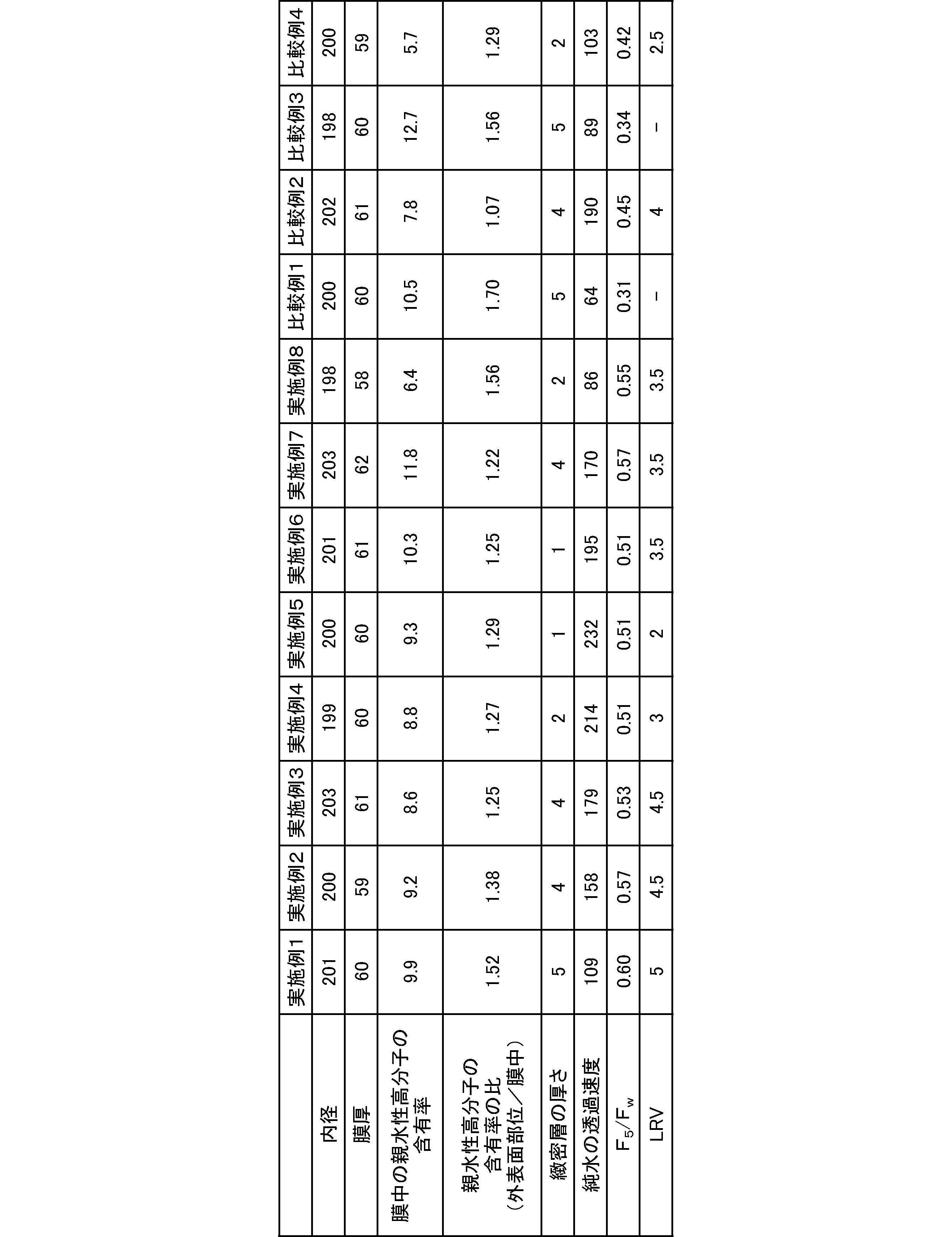
- Table 1 shows the measurement results of (1) to (7) for the porous hollow fiber filtration membranes obtained in Examples 1 to 8. All of the porous hollow fiber filtration membranes obtained in Examples 1 to 8 suppressed protein adsorption to the pore surface during filtration and were excellent in protein permeability.
- Example 1 A hollow fiber membrane was obtained in the same manner as in Example 1 except that the coagulating liquid composition was changed to 26.2 parts by mass of NMP, 29.0 parts by mass of TriEG, 36.8 parts by mass of water, and 8 parts by mass of VA64.
- Table 1 shows the measurement results of (1) to (7) for the hollow fiber membrane obtained in Comparative Example 1.
- the hollow fiber membrane obtained in Comparative Example 1 had a high content of hydrophilic polymer on the outer surface and did not show excellent protein permeability.
- Example 2 A hollow fiber membrane was obtained in the same manner as in Example 1 except that the coagulating liquid composition was changed to 28.5 parts by mass of NMP, 31.5 parts by mass of TriEG, and 40.0 parts by mass of water.
- Table 1 shows the measurement results of (1) to (7) for the hollow fiber membrane obtained in Comparative Example 2.
- the hollow fiber membrane obtained in Comparative Example 2 could not suppress protein adsorption in the dense layer and did not show excellent protein permeability.
- Example 3 A hollow fiber membrane was obtained in the same manner as in Example 7 except that the coagulating liquid composition was changed to 30.9 parts by mass of NMP, 34.2 parts by mass of TriEG, 27.9 parts by mass of water, and 7 parts by mass of VA64.
- Table 1 shows the measurement results of (1) to (7) for the hollow fiber membrane obtained in Comparative Example 3.
- the hollow fiber membrane obtained in Comparative Example 3 did not show excellent protein permeability because the hydrophilic polymer content was high and the pore diameter of the dense layer was small.
- Example 4 A hollow fiber membrane was obtained in the same manner as in Example 8 except that the coagulating liquid composition was changed to NMP 25.6 parts by mass, TriEG 28.3 parts by mass, water 44.1 parts by mass, and VA642 2 parts by mass.
- Table 1 shows the measurement results of (1) to (7) for the hollow fiber membrane obtained in Comparative Example 4.
- the hollow fiber membrane obtained in Comparative Example 4 had a low hydrophilic polymer content, could not suppress protein adsorption in the dense layer, and did not show excellent protein permeability.
- the porous hollow fiber filtration membrane in the present invention has industrial applicability in the purification process of plasma fractionation preparations and biopharmaceuticals.
- the porous hollow fiber filtration membrane can be used to remove a virus contained in a protein solution and recover a protein.
Landscapes
- Chemical & Material Sciences (AREA)
- Chemical Kinetics & Catalysis (AREA)
- Organic Chemistry (AREA)
- Biophysics (AREA)
- Analytical Chemistry (AREA)
- Health & Medical Sciences (AREA)
- Life Sciences & Earth Sciences (AREA)
- Biochemistry (AREA)
- Water Supply & Treatment (AREA)
- General Health & Medical Sciences (AREA)
- Genetics & Genomics (AREA)
- Medicinal Chemistry (AREA)
- Molecular Biology (AREA)
- Proteomics, Peptides & Aminoacids (AREA)
- Engineering & Computer Science (AREA)
- Separation Using Semi-Permeable Membranes (AREA)
Abstract
Description
血漿分画製剤やバイオ医薬品の精製工程において、ウイルス感染に対する安全性を付加する技術が用いられている。
安全性を付加する技術として、ウイルスを不活化する方法及びウイルスを除去する方法が挙げられる。
近年、ウイルスを不活化する方法における、タンパク質の変性、不活化効率、及び薬品の混入等の問題から、ウイルスの熱的及び化学的な性質にかかわらず、すべてのウイルスに有効な膜濾過法が広まっている。
ウイルス除去膜に求められる第二の性能は、生産性である。生産性とは、5nmサイズのアルブミンや10nmサイズのグロブリン等のタンパク質を効率的に回収することである。
生産性の観点から、孔径が数nm程度の限外濾過膜及び血液透析膜、並びにさらに小孔径の逆浸透膜は、濾過時にタンパク質が孔を閉塞させ、濾過中にFluxが低下し、タンパク質の回収効率が低下するため、ウイルス除去膜として適していない。また、パルボウイルス等の小さいウイルス除去を目的とした場合、ウイルスのサイズとタンパク質のサイズが近いため、上記の安全性と生産性を両立させる高度な技術が要求される。加えて、濾過中のFlux低下の原因は、サイズ因による孔の閉塞だけではなく、タンパク質の孔表面への吸着による孔の閉塞もある。
したがって、ウイルス除去膜は、孔径の精密な設計だけではなく、孔表面の設計も重要となる。
特許文献2には、ポリスルホン系高分子とビニルピロリドンと酢酸ビニルの共重合体のブレンド膜に多糖類誘導体がコーティングされたウイルス除去膜が開示されている。
特許文献2では、特許文献1と同様の方法で製膜した中空糸膜に多糖類誘導体を製膜後にコーティングすることにより、タンパク質溶液濾過中のタンパク質の膜への吸着による目詰まりを抑制している。このことから、特許文献1の方法で製膜された中空糸膜における親水性高分子の膜中の分散状態では、タンパク質の膜への吸着を十分に抑制できないことが推察される。また、製膜後に多糖類誘導体をコーティングすると、孔表面上の多糖類誘導体の分散状態の不均一性から、ビニルピロリドンと酢酸ビニルの共重合体の分散状態に不均一性が生じるため、孔表面上でのタンパク質の吸着のリスクが同レベルとならず、局所的なタンパク質の吸着が周囲に伝播し、目詰まりが起こるリスクが生じる。そして、タンパク質溶液を濾過することを目的とする膜においては、緻密層でのタンパク質の吸着を抑制する必要があるが、この課題はやはり解決されていない。
(1)
ポリスルホン系高分子と親水性高分子を含み、細孔の平均孔径が外表面から内表面に向かって大きくなる傾斜型非対称構造を有し、膜中の親水性高分子の含有率が6.0~12.0質量%であり、外表面の親水性高分子の含有率と膜中の親水性高分子の含有率の比が1.20~1.60である多孔質中空糸濾過膜。
(2)
純水の透過速度が60~200L/(hr・m2・bar)である、(1)に記載の多孔質中空糸濾過膜。
(3)
緻密層の厚みが2~10μmである、(1)または(2)に記載の多孔質中空糸濾過膜。
(4)
前記ポリスルホン系高分子が、ポリエーテルスルホンである、(1)~(3)のいずれかに記載の多孔質中空糸濾過膜。
(5)
前記親水性高分子が、ビニルピロリドンを含有する共重合体である、(1)~(4)のいずれかに記載の多孔質中空糸濾過膜。
(6)
タンパク質溶液に含まれるウイルスを除去し、タンパク質を回収するのに用いられる、(1)~(5)のいずれかに記載の多孔質中空糸濾過膜。
ポリスルホン系高分子とは、下記式1で示される繰り返し単位を有するポリスルホンであるか、下記式2で示される繰り返し単位を有するポリエーテルスルホンである。
ポリスルホン系高分子のうち、溶液中での会合体の形成防止等、溶解性の観点で、ポリエーテルスルホンが好ましい。


ポリスルホン系高分子は、単独で使用しても、2種以上を混合して使用してもよい。
ビニルピロリドンを含有する共重合体としては、ポリスルホン系高分子との相溶性の観点で、ビニルピロリドンと酢酸ビニルの共重合体が好ましい。ビニルピロリドンと酢酸ビニルの共重合比は、タンパク質の膜表面への吸着やポリスルホン系高分子との膜中での相互作用の観点から、6:4から9:1が好ましい。
ビニルピロリドンと酢酸ビニルの共重合体としては、具体的には、BASF社より市販されているLUVISKOL(商品名)VA64及びVA73等が挙げられる。
親水性高分子は、単独で使用しても、2種以上を混合して使用してもよい。
本実施形態において、内表面とは、多孔質中空糸濾過膜における中空糸の中空部側の表面を意味し、外表面とは、中空部表面とは膜厚方向に反対側の膜表面を意味する。
かかる数値化により、多孔質中空糸濾過膜が、細孔の平均孔径が外表面から内表面に向かって大きくなる傾斜型多孔質構造を有することを確認することができる。
本実施形態において、細孔の平均孔径が外表面から内表面に向かって大きくなる傾斜型非対称構造を有するとは、外表面から内表面に向かって、平均孔径が大きくなる傾向があることが確認できる構造であればよく、外表面から内表面側に向かって1μmの範囲の平均孔径が最小であり、内表面から外表面側に向かって1μmの範囲の平均孔径が最大であることを意味しない。
本実施形態においては、平均孔径が50nm以下であると算出された1μm×2μmの範囲は緻密層と定義する。
濾過上流側から濾過下流側に向けて、細孔の平均孔径が小さくなる膜は、濾過上流において大きな粒子を捕捉でき、大きな粒子の緻密層の閉塞によるFluxの低下を抑制することができる。
本実施形態においては、多孔質中空糸濾過膜が、細孔の平均孔径が外表面から内表面に向かって大きくなる傾斜型非対称構造を有するため、外表面側にある緻密層における細孔の閉塞によるFluxの低下を抑制することができる。
一つは、溶質のサイズよりも小さい細孔が、溶質により閉塞されるというサイズを因子(サイズ因)とするものであり、もう一つは、溶質が細孔表面に吸着することにより、細孔が閉塞されるという吸着を因子(吸着因)とするものである。
サイズ因による細孔の閉塞は濾過中断続的に起こり、吸着因による細孔の閉塞は、主に、濾過初期に観察される。
タンパク質透過性を向上させるためには、サイズ因に加え、緻密層における細孔表面へのタンパク質の吸着を抑制し、濾過初期の著しいFlux低下を抑制することが重要である。
本実施形態においては、外表面及び膜中での親水性高分子の含有量を制御することにより、緻密層における細孔表面へのタンパク質の吸着を抑制し、吸着によるFlux低下を抑制することができる。
外表面及び膜中での親水性高分子の含有量として、膜中の親水性高分子の含有率を6.0~12.0質量%とすることにより、孔表面上の親水性高分子の厚みによる細孔の縮小を抑制することができる。また、外表面及び膜中での親水性高分子の含有量として、膜中の親水性高分子の含有率を6.0~12.0質量%とし、外表面の親水性高分子の含有率と膜中の親水性高分子の含有率の比を1.20~1.60とすることにより、Flux低下を抑制することができる。
多孔質中空糸濾過膜を厚さ10μmで膜厚方向に切断する。切断した多孔質中空糸濾過膜断片を臭化カリウム板ではさみ、5×5μmを1セグメントとし、顕微FT-IRにより透過法で膜厚方向に連続的に測定する。測定したスペクトルよりポリスルホン系高分子由来のピーク(1580cm-1付近)と親水性高分子由来のピーク(例えば、カルボニル結合を有する親水性高分子ならば、1730cm-1付近、例えば、エーテル結合を有する親水性高分子ならば、1100cm-1付近)を検出し、親水性高分子由来のピークの吸光度面積/ポリスルホン系高分子由来のピークの吸光度面積比より、各分割したセグメントにおける親水性高分子の含有率として算出する。
各セグメントの親水性高分子の含有率の平均値を親水性高分子の膜中の含有率とする。
膜厚方向で最外表面側のセグメントの親水性高分子の含有率/親水性高分子の膜中の含有率を外表面の親水性高分子の含有率と膜中の親水性高分子の含有率の比として算出する。
免疫グロブリンの濾過試験は実施例に記載の方法により行うことができる。
免疫グロブリンの濾過試験において、Flux低下を抑制しているということは、1.5質量%の免疫グロブリンを2.0barで定圧濾過したときの、濾過開始後5分経過時のFlux(F5)と純水を1.0barで定圧濾過した時の透水量を2倍した値(Fw)の比(F5/Fw)が0.50以上であることである。
高い濾過圧での操作は、基材に耐圧性を有するポリスルホン系高分子を用いることにより実現される。
タンパク質溶液は純水に比べ溶液の粘度が高くなるため、純水の透過速度よりも低くなるが、純水の透過速度が高いほど、タンパク質溶液の濾過速度は高くなる。本実施形態の多孔質中空糸濾過膜の純水の透過速度は60~200L/(hr・m2・bar)が好ましく、100~180L/(hr・m2・bar)がより好ましい。
純水の透過速度が60L/(hr・m2・bar)以上であることにより、濾過時間が長過ぎず、高効率にタンパク質を回収可能である。また、純水の透過速度が200L/(hr・m2・bar)以下であることにより、ウイルス除去性能を発揮することができる。
純水の透過速度は実施例に記載の方法により測定することができる。
ウイルスを含んだタンパク質溶液は透過方向に対して垂直なウイルス捕捉面が何層も重なったウイルス除去層を透過する。
ウイルス捕捉面中の細孔の大きさには必ず分布が存在し、ウイルスのサイズよりも小さな細孔の部分でウイルスが捕捉される。一つのウイルス捕捉面でのウイルス捕捉率は低いが、ウイルス捕捉面が何層も重なることにより、高いウイルス除去性能が実現される。例えば、一つのウイルス捕捉面でのウイルス捕捉率が20%であっても、ウイルス捕捉面が50層重なることにより、全体としてのウイルス捕捉率は99.999%となる。
ウイルス除去膜では、ウイルスは多層で捕捉することによりウイルス捕捉能力を高くすることができるため、緻密層を厚くすることが好ましい。タンパク質のFlux低下抑制の観点から、緻密層の厚さを一定の範囲内にすることが好ましい。
ウイルス除去の安全性とタンパク質回収効率の生産性を両立させる観点から、緻密層の厚さは2~10μmであることが好ましく、2~8μmであることがより好ましい。
パルボウイルスとして、実液に近いもの、操作性の簡便性からブタパルボウイルス(PPV)であることが好ましい。
PPVのLRVは実施例に記載の方法により測定することができる。
例えば、ポリスルホン系高分子、親水性高分子、及び溶媒を混合溶解し、脱泡したものを製膜原液とし、内液(芯液)とともに、二重管ノズル(紡口)の環状部、中心部からそれぞれ同時に吐出し、空走部を経て凝固液中に導いて中空糸を形成する。得られた中空糸を、水洗後巻取り、中空部内の液抜き、熱処理、乾燥させる。
ジオール化合物とは、分子の両末端に水酸基を有する化合物であり、ジオール化合物としては、下記式3で表され、繰り返し単位nが1以上のエチレングリコール構造を有する化合物が好ましい。
ジオール化合物としては、例えば、ジエチレングリコール(DEG)、トリエチレングリコール(TriEG)、テトラエチレングリコール(TetraEG)、及びポリエチレングリコール等が挙げられ、DEG、TriEG、及びTetraEGが好ましく、TriEGがより好ましい。

製膜原液中のポリスルホン系高分子の濃度を15質量%以上とすることにより、適当な膜強度とすることができると共に、空孔率を上げることにより高い透過性能を得ることができる。製膜原液中のポリスルホン系高分子の濃度を35質量%以下にすることにより、空孔率が低くなり過ぎず、透過性能を維持できるだけでなく、膜のウイルス捕捉容量が高く保つことができる。
製膜原液中の親水性高分子の濃度が5質量%以上とすることにより、得られる膜が十分に親水性化される。タンパク質溶液の濾過に使用する場合でも、タンパク質が膜に吸着しにくく、Flux低下が起こり難い観点で、濃度が5質量%以上であることが好ましい。製膜原液中の親水性高分子の濃度を12質量%以下とすることにより、得られる膜において孔表面上の親水性高分子の厚みが厚過ぎず、過度に孔径が小さくならないので好ましい。また、乾燥後に中空糸同士が固着する糸付きを防止する観点で、濃度を12質量%以下であることが好ましい。
脱泡工程は以下のように行うことができる。
完全に溶解された製膜原液が入ったタンク内を50℃に加温し、2kPaまで減圧し、1時間以上静置する。この操作を7回以上繰り返すことが好ましい。脱泡するときの圧力は溶媒の沸点より高くすることが好ましい。脱泡効率をあげるため、脱泡中に製膜原液を撹拌してもよい。
製膜原液タンクのパッキン等からの異物の混入を除去するために、製膜原液が紡口から吐出される前に、フィルターを設置することが好ましく、孔径違いのフィルターを多段で設置することがより好ましい。具体的には、製膜原液タンクに近い方から、順に孔径10μmのメッシュフィルター、孔径3μmのメッシュフィルターを設置するのが好ましい。
内液中の溶媒量が多くなると、凝固の進行を遅らせ、膜構造形成をゆっくりと進行させる効果があり、非溶媒量が多くなると、増粘効果により、溶液の拡散を遅らし、凝固の進行を遅らせ、膜構造形成をゆっくりと進行させる効果があり、水が多くなると、凝固の進行を早める効果がある。
凝固の進行を適切に進行させ、膜構造を制御し、本実施形態の多孔質中空糸濾過膜の好ましい膜構造を得るためには、内液中の有機成分である溶媒/非溶媒の比率を質量比でほぼ同量、例えば35/65~65/35とし、有機成分/水の比率を質量比で70/30~100/0にすることが好ましい。
製膜原液は紡口から吐出された後、空走部を経て、凝固浴に導入される。空走部の滞留時間は0.01~0.75秒が好ましく、0.05~0.4秒がより好ましい。滞留時間を0.01秒以上とすることにより、凝固浴導入までの凝固を十分に進め、適当な孔径とすることができる。滞留時間を0.75秒以下とすることにより、凝固の過度な進行を防ぎ、凝固浴での精密な膜構造制御を可能にする。
ドラフト比が高いとは、紡口から吐出されてからの延伸比が高いことを意味する。
一般的に、湿式相分離法で製膜されるとき、製膜原液が空走部を経て、凝固浴を出たときに、大方の膜構造が決定される。膜内部は、高分子鎖が絡み合うことにより形成される実部と高分子が存在しない空孔部となっている虚部から構成される。詳細な機構は不明であるが、凝固が完了する前に中空糸膜が過度に延伸されると、言い換えると、高分子鎖が絡み合う前に過度に延伸されると、高分子鎖の絡み合いが引き裂かれ、空孔部が連結されることにより、過度に大きな孔が形成されたり、空孔部が分割されることにより、過度に小さな孔が形成される。過度に大きな孔はウイルス漏れの原因となり、過度に小さな孔は目詰まりの原因となる。わずかな構造欠陥でも、ウイルス除去を目的とした膜においては、致命的となるため、ドラフト比は極力小さくすることが好ましい。
凝固浴温度は、孔径制御の観点で、30~60℃が好ましい。
温水での水洗工程では、溶媒と膜に固定化されていない親水性高分子を確実に除去することが好ましい。中空糸膜が溶媒を含んだまま乾燥されると、乾燥中に膜内で溶媒が濃縮され、ポリスルホン系高分子が溶解または膨潤することにより、膜構造を変化させる可能性があり、膜に固定化されていない親水性高分子が残存すると、孔を閉塞させ、膜の透過性を低下させる可能性がある。除去すべき溶媒及び非溶媒並びに膜に固定化されていない親水性高分子の拡散速度を高め、水洗効率を上げるため、温水の温度は50℃以上が好ましい。水洗工程は、ネルソンローラを使用することが好ましい。十分に水洗を行うため、中空糸膜の水洗浴中の滞留時間は残存したNMPにより、ウイルス除去膜として好ましくない膜構造に変化するのを防止する観点で80秒以上が好ましく、不要成分の除去を目的とした水洗工程は長いほど好ましいが、生産効率の点から、300秒以下とすることが適当である。
熱水処理工程では、中空糸膜の内表面側からも洗浄されるため、水洗工程で除去しきれなかった、膜に固定されなかった親水性高分子等が効率的に除去される。熱水の温度は50~100℃が好ましい。熱水の温度は50℃以上とすることが、洗浄効率を高くできる点で、好ましい。洗浄時間は30~120分が好ましい。熱水は洗浄中に数回、交換することが好ましい。
多孔質中空糸濾過膜の内径は、膜の垂直割断面を実体顕微鏡で撮影することにより求めた。
内径と同様に外径を求め、(外径-内径)/2より膜厚を算出した。
また、膜面積として、内径×π×多孔質中空糸濾過膜の有効長とした。
1.0barの定圧デッドエンド濾過による25℃の純水の濾過量を測定し、濾過時間から透水量を測定して、純水の透過速度とした。
多孔質中空糸濾過膜の本数が4本、有効長が8cmになるように組み立てられたフィルターを122℃で60分高圧滅菌処理をした。献血ヴェノグロブリンIH 5%静注(2.5g/50mL)(田辺三菱製薬社製)を用いて、溶液の免疫グロブリン濃度が1.5質量%、塩化ナトリウム濃度が0.1M、pHが4.5になるように溶液を調製した。調製した溶液をデッドエンドで、2.0barの一定圧力で濾過を行った。濾過開始5分経過時の積算濾過量/5をF5とし、(2)において測定した透水量より、F5/Fwを算出した。
(3)免疫グロブリンの濾過試験において調製した溶液に0.5容量%のPPV溶液をspikeした溶液を濾過溶液とした。(3)免疫グロブリンの濾過試験と同様にして濾過試験を行った。濾液のTiter(TCID50値)をウイルスアッセイにて測定した。PPVのウイルスクリアランスはLRV=Log(TCID50)/mL(濾過溶液)-Log(TCID50)/mL(濾液)により算出した。
中空糸膜断面を走査型電子顕微鏡(SEM)により、撮影倍率を50,000倍、中空糸断面の膜厚方向に対して水平に視野を設定して撮影した。設定した一視野での撮影後、膜厚方向に対して水平に撮影視野を移動し、次の視野を撮影した。この撮影操作を繰り返し、隙間なく膜断面の写真を撮影し、得られた写真を結合して一枚の膜断面写真を得た。この断面写真において、(膜の円周方向に2μm)×(外表面から内表面側に向かって1μm)の範囲における平均孔径を算出し、外表面から内表面側に向かって1μm毎に膜断面の傾斜構造を数値化した。平均孔径は、以下のようにして算出した。MediaCybernetics社製Imagepro-plusを用いて、明度を基準に空孔部と実部を識別し、識別できなかった部分やノイズをフリーハンドツールで補正し、空孔部の輪郭となるエッジ部分や、空孔部の奥に観察される多孔構造は空孔部として識別して、空孔部と実部の二値化処理を行った。二値化処理の後、空孔/1個の面積値を真円と仮定し、空孔の直径を算出した。視野の端部で途切れた空孔部についてもカウントして、全ての孔毎に実施し、2μm×1μmの範囲毎に平均孔径を算出した。平均孔径が50nm以下の範囲を緻密層と定義し、平均孔径が50nm超の範囲を粗大層と定義した。
緻密層の厚みは、「平均孔径50nm以下を示した範囲の数×1μm」として測定した。
多孔質中空糸濾過膜を厚さ10μmで膜厚方向に切断した。切断した多孔質中空糸濾過膜断片を臭化カリウム板ではさみ、プレス機を用いて錠剤を成型した。錠剤としたものを顕微FT-IRにより透過法で、5×5μmを1セグメントとし、膜厚方向に連続的に測定した。測定したスペクトルよりポリスルホン系高分子由来のピークと親水性高分子由来のピークを検出し、親水性高分子由来のピークの吸光度面積/ポリスルホン系高分子由来のピークの吸光度面積比より、各分割したセグメントにおける親水性高分子の含有率として算出した。
各セグメントの親水性高分子の含有率の平均値を親水性高分子の膜中の含有率とした。
膜厚方向で最外表面側のセグメントの親水性高分子の含有率/親水性高分子の膜中の含有率を外表面の親水性高分子の含有率と膜中の親水性高分子の含有率の比として算出した。
ポリエーテルスルホン(PES)27質量部(BASF社製Ultrason(商品名)E6020P)、ビニルピロリドンと酢酸ビニルの共重合体(BASF社製Luviskol(登録商標)VA64、以下、「VA64」と記載する)9質量部、NMP(キシダ化学社製)30.4質量部、及びTriEG(関東化学社製)33.6質量部を50℃で混合した後、減圧脱泡を7回繰り返した溶液を製膜原液とした。二重管ノズルの環状部から紡口温度は50℃に設定して、製膜原液を吐出し、中心部からNMP45.1質量部、TriEG49.9質量部、及び水5質量部の混合液を内液として吐出した。
吐出された製膜原液と内液は、空走部を経て、30℃、NMP26.8質量部、TriEG29.6質量部、水37.6質量部、及びVA64 6質量部からなる凝固液を走行させた。凝固浴から引き出された中空糸膜は、55℃に設定された水洗槽をネルソンロール走行させた後、水中で巻き取った。紡糸速度は8m/minとし、ドラフト比は2とした。巻き取られた中空糸膜は両端を切断し、束にし、弛まないように支持体に把持させ、80℃の熱水に浸漬させ、60分間洗浄した。洗浄された中空糸膜は128℃、6時間の条件で、高圧熱水処理された後、真空乾燥して、多孔質中空糸濾過膜を得た。
凝固浴組成をNMP27.4質量部、TriEG30.2質量部、水38.4質量部、及びVA64 4質量部に変更した以外は実施例1と同様にして多孔質中空糸濾過膜を得た。
凝固浴組成をNMP28.0質量部、TriEG30.8質量部、水39.2質量部、及びVA64 2質量部に変更した以外は実施例1と同様にして多孔質中空糸濾過膜を得た。
凝固浴組成をNMP18.6質量部、TriEG20.6質量部、水58.8質量部、及びVA64 2質量部に変更した以外は実施例1と同様にして多孔質中空糸濾過膜を得た。
凝固浴組成をNMP9.3質量部、TriEG10.3質量部、水78.4質量部、及びVA64 2質量部に変更した以外は実施例1と同様にして多孔質中空糸濾過膜を得た。
製膜原液組成をPES26質量部、VA64 10質量部、NMP32質量部、及びTriEG32質量部に変更した以外は実施例5と同様にして多孔質中空糸濾過膜を得た。
製膜原液組成をPES24質量部、VA64 12質量部、NMP30.4質量部、及びTriEG33.6質量部にし、凝固液組成をNMP37.3質量部、TriEG29.9質量部、水28.8質量部、及びVA64 4質量部に変更した以外は実施例1と同様にして多孔質中空糸濾過膜を得た。
製膜原液組成をPES30質量部、VA64 6質量部、NMP30.4質量部、及びTriEG33.6質量部にし、凝固液組成をNMP24.8質量部、TriEG27.4質量部、水42.8質量部、及びVA64 5質量部に変更した以外は実施例1と同様にして多孔質中空糸濾過膜を得た。
実施例1~8で得られた多孔質中空糸濾過膜はいずれも、濾過中の細孔表面へのタンパク質の吸着を抑制し、タンパク質透過性に優れていた。
凝固液組成をNMP26.2質量部、TriEG29.0質量部、水36.8質量部、及びVA64 8質量部に変更した以外は実施例1と同様に中空糸膜を得た。
凝固液組成をNMP28.5質量部、TriEG31.5質量部、及び水40.0質量部に変更した以外は実施例1と同様に中空糸膜を得た。
凝固液組成をNMP30.9質量部、TriEG34.2質量部、水27.9質量部、及びVA64 7質量部に変更した以外は実施例7と同様に中空糸膜を得た。
凝固液組成をNMP25.6質量部、TriEG28.3質量部、水44.1質量部、及びVA64 2質量部に変更した以外は実施例8と同様に中空糸膜を得た。
Claims (6)
- ポリスルホン系高分子と親水性高分子を含み、細孔の平均孔径が外表面から内表面に向かって大きくなる傾斜型非対称構造を有し、膜中の親水性高分子の含有率が6.0~12.0質量%であり、外表面の親水性高分子の含有率と膜中の親水性高分子の含有率の比が1.20~1.60である多孔質中空糸濾過膜。
- 純水の透過速度が60~200L/(hr・m2・bar)である、請求項1に記載の多孔質中空糸濾過膜。
- 緻密層の厚みが2~10μmである、請求項1または2に記載の多孔質中空糸濾過膜。
- 前記ポリスルホン系高分子が、ポリエーテルスルホンである、請求項1~3のいずれか1項に記載の多孔質中空糸濾過膜。
- 前記親水性高分子が、ビニルピロリドンを含有する共重合体である、請求項1~4のいずれか1項に記載の多孔質中空糸濾過膜。
- タンパク質溶液に含まれるウイルスを除去し、タンパク質を回収するのに用いられる、請求項1~5のいずれかに記載の多孔質中空糸濾過膜。
Priority Applications (3)
| Application Number | Priority Date | Filing Date | Title |
|---|---|---|---|
| JP2016570659A JP6433513B2 (ja) | 2015-01-19 | 2016-01-19 | 多孔質中空糸濾過膜 |
| EP16740172.8A EP3248672A4 (en) | 2015-01-19 | 2016-01-19 | Porous hollow fiber filtration membrane |
| US15/544,342 US20170348650A1 (en) | 2015-01-19 | 2016-01-19 | Porous hollow fiber filtration membrane |
Applications Claiming Priority (2)
| Application Number | Priority Date | Filing Date | Title |
|---|---|---|---|
| JP2015-008058 | 2015-01-19 | ||
| JP2015008058 | 2015-01-19 |
Publications (1)
| Publication Number | Publication Date |
|---|---|
| WO2016117565A1 true WO2016117565A1 (ja) | 2016-07-28 |
Family
ID=56417106
Family Applications (1)
| Application Number | Title | Priority Date | Filing Date |
|---|---|---|---|
| PCT/JP2016/051458 Ceased WO2016117565A1 (ja) | 2015-01-19 | 2016-01-19 | 多孔質中空糸濾過膜 |
Country Status (4)
| Country | Link |
|---|---|
| US (1) | US20170348650A1 (ja) |
| EP (1) | EP3248672A4 (ja) |
| JP (1) | JP6433513B2 (ja) |
| WO (1) | WO2016117565A1 (ja) |
Cited By (11)
| Publication number | Priority date | Publication date | Assignee | Title |
|---|---|---|---|---|
| WO2018084131A1 (ja) * | 2016-11-04 | 2018-05-11 | 旭化成メディカル株式会社 | 多孔膜及び多孔膜の製造方法 |
| WO2018088451A1 (ja) * | 2016-11-11 | 2018-05-17 | 富士フイルム株式会社 | 免疫隔離膜、移植用チャンバー、および移植用デバイス |
| WO2018088452A1 (ja) * | 2016-11-11 | 2018-05-17 | 富士フイルム株式会社 | 免疫隔離膜、移植用チャンバー、および移植用デバイス |
| WO2019004377A1 (ja) * | 2017-06-29 | 2019-01-03 | 富士フイルム株式会社 | 移植用チャンバーおよび移植用デバイス |
| US20200038778A1 (en) * | 2017-02-17 | 2020-02-06 | Bayer Aktiengesellschaft | Degassing in methods for continuous processing of a healthcare product |
| CN110809479A (zh) * | 2017-06-29 | 2020-02-18 | 富士胶片株式会社 | 移植用室及移植用器件 |
| WO2021100804A1 (ja) | 2019-11-21 | 2021-05-27 | 東レ株式会社 | 多孔質分離膜 |
| CN113856495A (zh) * | 2021-09-18 | 2021-12-31 | 杭州科百特过滤器材有限公司 | 一种除病毒用不对称的聚醚砜滤膜及其制备方法 |
| CN114452844A (zh) * | 2022-01-29 | 2022-05-10 | 杭州科百特过滤器材有限公司 | 一种用于生物大分子纯化的pes中空纤维膜及其制备方法与应用 |
| WO2022165329A1 (en) | 2021-02-01 | 2022-08-04 | Chemours-Mitsui Fluoroproducts Co., Ltd | Porous membrane prepared by stretching heat-treated sheet comprising polytetrafluoroethylene and/or modified polytetrafluoroethylene |
| US12274985B2 (en) | 2019-03-29 | 2025-04-15 | Asahi Kasei Medical Co., Ltd. | Porous membrane |
Families Citing this family (2)
| Publication number | Priority date | Publication date | Assignee | Title |
|---|---|---|---|---|
| CN113842792A (zh) * | 2021-09-18 | 2021-12-28 | 杭州科百特过滤器材有限公司 | 一种除病毒用不对称的pes滤膜及其制备方法 |
| CN121219065A (zh) | 2023-05-25 | 2025-12-26 | 旭化成生命科学股份有限公司 | 多孔膜 |
Citations (10)
| Publication number | Priority date | Publication date | Assignee | Title |
|---|---|---|---|---|
| WO1995033549A1 (en) * | 1994-06-07 | 1995-12-14 | Mitsubishi Rayon Co., Ltd. | Porous polysulfone membrane and process for producing the same |
| JPH10180058A (ja) * | 1996-12-24 | 1998-07-07 | Toyobo Co Ltd | 中空糸膜 |
| JP2004525755A (ja) * | 2001-01-23 | 2004-08-26 | アマシャム・バイオサイエンス・メムブレイン・セパレイションズ・コーポレイション | アシンメトリー中空ファイバー膜 |
| JP2005342139A (ja) * | 2004-06-02 | 2005-12-15 | Toyobo Co Ltd | ポリスルホン系選択透過性中空糸膜 |
| JP2007136449A (ja) * | 2005-10-14 | 2007-06-07 | Millipore Corp | 限外ろ過膜、ならびに限外ろ過膜の製造および使用の方法 |
| WO2010035793A1 (ja) * | 2008-09-26 | 2010-04-01 | 旭化成ケミカルズ株式会社 | 清澄化されたバイオ医薬培養液を製造するための多孔質中空糸膜の使用 |
| WO2011111679A1 (ja) * | 2010-03-09 | 2011-09-15 | 東洋紡績株式会社 | タンパク質含有液処理用多孔質中空糸膜 |
| WO2013012024A1 (ja) * | 2011-07-21 | 2013-01-24 | 東洋紡株式会社 | 多孔質中空糸膜 |
| JP2014015411A (ja) * | 2012-07-06 | 2014-01-30 | Asahi Kasei Medical Co Ltd | タンパク質の製造方法 |
| WO2014077095A1 (ja) * | 2012-11-15 | 2014-05-22 | 東洋紡株式会社 | 多孔質中空糸膜 |
Family Cites Families (3)
| Publication number | Priority date | Publication date | Assignee | Title |
|---|---|---|---|---|
| JP3279018B2 (ja) * | 1993-11-12 | 2002-04-30 | エヌオーケー株式会社 | 多孔質膜の製造方法 |
| JP3594032B1 (ja) * | 2003-08-29 | 2004-11-24 | 東洋紡績株式会社 | 高透水性中空糸膜型血液浄化器 |
| JP3551971B1 (ja) * | 2003-11-26 | 2004-08-11 | 東洋紡績株式会社 | ポリスルホン系選択透過性中空糸膜 |
-
2016
- 2016-01-19 JP JP2016570659A patent/JP6433513B2/ja active Active
- 2016-01-19 US US15/544,342 patent/US20170348650A1/en not_active Abandoned
- 2016-01-19 WO PCT/JP2016/051458 patent/WO2016117565A1/ja not_active Ceased
- 2016-01-19 EP EP16740172.8A patent/EP3248672A4/en not_active Withdrawn
Patent Citations (10)
| Publication number | Priority date | Publication date | Assignee | Title |
|---|---|---|---|---|
| WO1995033549A1 (en) * | 1994-06-07 | 1995-12-14 | Mitsubishi Rayon Co., Ltd. | Porous polysulfone membrane and process for producing the same |
| JPH10180058A (ja) * | 1996-12-24 | 1998-07-07 | Toyobo Co Ltd | 中空糸膜 |
| JP2004525755A (ja) * | 2001-01-23 | 2004-08-26 | アマシャム・バイオサイエンス・メムブレイン・セパレイションズ・コーポレイション | アシンメトリー中空ファイバー膜 |
| JP2005342139A (ja) * | 2004-06-02 | 2005-12-15 | Toyobo Co Ltd | ポリスルホン系選択透過性中空糸膜 |
| JP2007136449A (ja) * | 2005-10-14 | 2007-06-07 | Millipore Corp | 限外ろ過膜、ならびに限外ろ過膜の製造および使用の方法 |
| WO2010035793A1 (ja) * | 2008-09-26 | 2010-04-01 | 旭化成ケミカルズ株式会社 | 清澄化されたバイオ医薬培養液を製造するための多孔質中空糸膜の使用 |
| WO2011111679A1 (ja) * | 2010-03-09 | 2011-09-15 | 東洋紡績株式会社 | タンパク質含有液処理用多孔質中空糸膜 |
| WO2013012024A1 (ja) * | 2011-07-21 | 2013-01-24 | 東洋紡株式会社 | 多孔質中空糸膜 |
| JP2014015411A (ja) * | 2012-07-06 | 2014-01-30 | Asahi Kasei Medical Co Ltd | タンパク質の製造方法 |
| WO2014077095A1 (ja) * | 2012-11-15 | 2014-05-22 | 東洋紡株式会社 | 多孔質中空糸膜 |
Cited By (24)
| Publication number | Priority date | Publication date | Assignee | Title |
|---|---|---|---|---|
| JPWO2018084131A1 (ja) * | 2016-11-04 | 2019-07-11 | 旭化成メディカル株式会社 | 多孔膜及び多孔膜の製造方法 |
| WO2018084131A1 (ja) * | 2016-11-04 | 2018-05-11 | 旭化成メディカル株式会社 | 多孔膜及び多孔膜の製造方法 |
| AU2017354687B2 (en) * | 2016-11-04 | 2020-02-27 | Asahi Kasei Medical Co., Ltd. | Porous membrane and method for manufacturing porous membrane |
| CN109982727B (zh) * | 2016-11-11 | 2022-01-21 | 富士胶片株式会社 | 免疫隔离膜、移植用室及移植用器件 |
| WO2018088452A1 (ja) * | 2016-11-11 | 2018-05-17 | 富士フイルム株式会社 | 免疫隔離膜、移植用チャンバー、および移植用デバイス |
| CN109982727A (zh) * | 2016-11-11 | 2019-07-05 | 富士胶片株式会社 | 免疫隔离膜、移植用室及移植用器件 |
| WO2018088451A1 (ja) * | 2016-11-11 | 2018-05-17 | 富士フイルム株式会社 | 免疫隔離膜、移植用チャンバー、および移植用デバイス |
| JPWO2018088452A1 (ja) * | 2016-11-11 | 2019-10-03 | 富士フイルム株式会社 | 免疫隔離膜、移植用チャンバー、および移植用デバイス |
| JPWO2018088451A1 (ja) * | 2016-11-11 | 2019-10-03 | 富士フイルム株式会社 | 免疫隔離膜、移植用チャンバー、および移植用デバイス |
| EP3539575A4 (en) * | 2016-11-11 | 2019-11-13 | FUJIFILM Corporation | IMMUNIZATION MEMBRANE, TRANSPLANT CHAMBER AND TRANSPLANT DEVICE |
| US11051930B2 (en) | 2016-11-11 | 2021-07-06 | Fujifilm Corporation | Membrane for immunoisolation, chamber for transplantation, and device for transplantation |
| US11045587B2 (en) | 2016-11-11 | 2021-06-29 | Fujifilm Corporation | Membrane for immunoisolation, chamber for transplantation, and device for transplantation |
| CN109922839A (zh) * | 2016-11-11 | 2019-06-21 | 富士胶片株式会社 | 免疫隔离膜、移植用室及移植用器件 |
| US20200038778A1 (en) * | 2017-02-17 | 2020-02-06 | Bayer Aktiengesellschaft | Degassing in methods for continuous processing of a healthcare product |
| US11771806B2 (en) | 2017-06-29 | 2023-10-03 | Fujifilm Corporation | Chamber for transplantation and device for transplantation |
| CN110831637A (zh) * | 2017-06-29 | 2020-02-21 | 富士胶片株式会社 | 移植用室及移植用器件 |
| CN110809479A (zh) * | 2017-06-29 | 2020-02-18 | 富士胶片株式会社 | 移植用室及移植用器件 |
| WO2019004377A1 (ja) * | 2017-06-29 | 2019-01-03 | 富士フイルム株式会社 | 移植用チャンバーおよび移植用デバイス |
| US12274985B2 (en) | 2019-03-29 | 2025-04-15 | Asahi Kasei Medical Co., Ltd. | Porous membrane |
| WO2021100804A1 (ja) | 2019-11-21 | 2021-05-27 | 東レ株式会社 | 多孔質分離膜 |
| WO2022165329A1 (en) | 2021-02-01 | 2022-08-04 | Chemours-Mitsui Fluoroproducts Co., Ltd | Porous membrane prepared by stretching heat-treated sheet comprising polytetrafluoroethylene and/or modified polytetrafluoroethylene |
| CN113856495A (zh) * | 2021-09-18 | 2021-12-31 | 杭州科百特过滤器材有限公司 | 一种除病毒用不对称的聚醚砜滤膜及其制备方法 |
| CN114452844A (zh) * | 2022-01-29 | 2022-05-10 | 杭州科百特过滤器材有限公司 | 一种用于生物大分子纯化的pes中空纤维膜及其制备方法与应用 |
| CN114452844B (zh) * | 2022-01-29 | 2023-12-29 | 杭州科百特过滤器材有限公司 | 一种用于生物大分子纯化的pes中空纤维膜及其制备方法与应用 |
Also Published As
| Publication number | Publication date |
|---|---|
| JPWO2016117565A1 (ja) | 2017-09-28 |
| US20170348650A1 (en) | 2017-12-07 |
| EP3248672A4 (en) | 2018-01-10 |
| EP3248672A1 (en) | 2017-11-29 |
| JP6433513B2 (ja) | 2018-12-05 |
Similar Documents
| Publication | Publication Date | Title |
|---|---|---|
| JP6433513B2 (ja) | 多孔質中空糸濾過膜 | |
| JP6385444B2 (ja) | 多孔質膜 | |
| JP6522001B2 (ja) | 中空糸濾過膜 | |
| JP6024660B2 (ja) | 多孔質中空糸膜 | |
| JP5504560B2 (ja) | 液体処理用の中空糸膜 | |
| CN104602798B (zh) | 选择性渗透的不对称膜 | |
| JP6367977B2 (ja) | 多孔質中空糸膜 | |
| JP5835659B2 (ja) | タンパク質含有液処理用多孔質中空糸膜 | |
| JP6770807B2 (ja) | 中空糸膜 | |
| JP7185766B2 (ja) | 多孔質膜 | |
| WO2024242161A1 (ja) | 多孔質膜 | |
| JP2011020071A (ja) | ポリスルホン系中空糸膜の製造方法 | |
| JP2024168853A (ja) | 多孔質膜 | |
| WO2024128243A1 (ja) | 多孔質膜および精製方法 | |
| CN117942791A (zh) | 病毒去除膜以及其制造方法和使用方法 |
Legal Events
| Date | Code | Title | Description |
|---|---|---|---|
| 121 | Ep: the epo has been informed by wipo that ep was designated in this application |
Ref document number: 16740172 Country of ref document: EP Kind code of ref document: A1 |
|
| ENP | Entry into the national phase |
Ref document number: 2016570659 Country of ref document: JP Kind code of ref document: A |
|
| REEP | Request for entry into the european phase |
Ref document number: 2016740172 Country of ref document: EP |
|
| WWE | Wipo information: entry into national phase |
Ref document number: 15544342 Country of ref document: US |
|
| NENP | Non-entry into the national phase |
Ref country code: DE |