WO2016117502A1 - 接合構造体及び接合構造体の製造方法 - Google Patents
接合構造体及び接合構造体の製造方法 Download PDFInfo
- Publication number
- WO2016117502A1 WO2016117502A1 PCT/JP2016/051276 JP2016051276W WO2016117502A1 WO 2016117502 A1 WO2016117502 A1 WO 2016117502A1 JP 2016051276 W JP2016051276 W JP 2016051276W WO 2016117502 A1 WO2016117502 A1 WO 2016117502A1
- Authority
- WO
- WIPO (PCT)
- Prior art keywords
- metal member
- region
- joining
- laser
- bonding
- Prior art date
- Legal status (The legal status is an assumption and is not a legal conclusion. Google has not performed a legal analysis and makes no representation as to the accuracy of the status listed.)
- Ceased
Links
Images








Classifications
-
- B—PERFORMING OPERATIONS; TRANSPORTING
- B29—WORKING OF PLASTICS; WORKING OF SUBSTANCES IN A PLASTIC STATE IN GENERAL
- B29C—SHAPING OR JOINING OF PLASTICS; SHAPING OF MATERIAL IN A PLASTIC STATE, NOT OTHERWISE PROVIDED FOR; AFTER-TREATMENT OF THE SHAPED PRODUCTS, e.g. REPAIRING
- B29C65/00—Joining or sealing of preformed parts, e.g. welding of plastics materials; Apparatus therefor
- B29C65/02—Joining or sealing of preformed parts, e.g. welding of plastics materials; Apparatus therefor by heating, with or without pressure
- B29C65/14—Joining or sealing of preformed parts, e.g. welding of plastics materials; Apparatus therefor by heating, with or without pressure using wave energy, i.e. electromagnetic radiation, or particle radiation
- B29C65/16—Laser beams
- B29C65/1603—Laser beams characterised by the type of electromagnetic radiation
- B29C65/1612—Infrared [IR] radiation, e.g. by infrared lasers
- B29C65/1616—Near infrared radiation [NIR], e.g. by YAG lasers
-
- B—PERFORMING OPERATIONS; TRANSPORTING
- B23—MACHINE TOOLS; METAL-WORKING NOT OTHERWISE PROVIDED FOR
- B23K—SOLDERING OR UNSOLDERING; WELDING; CLADDING OR PLATING BY SOLDERING OR WELDING; CUTTING BY APPLYING HEAT LOCALLY, e.g. FLAME CUTTING; WORKING BY LASER BEAM
- B23K26/00—Working by laser beam, e.g. welding, cutting or boring
- B23K26/20—Bonding
- B23K26/32—Bonding taking account of the properties of the material involved
- B23K26/324—Bonding taking account of the properties of the material involved involving non-metallic parts
-
- B—PERFORMING OPERATIONS; TRANSPORTING
- B23—MACHINE TOOLS; METAL-WORKING NOT OTHERWISE PROVIDED FOR
- B23K—SOLDERING OR UNSOLDERING; WELDING; CLADDING OR PLATING BY SOLDERING OR WELDING; CUTTING BY APPLYING HEAT LOCALLY, e.g. FLAME CUTTING; WORKING BY LASER BEAM
- B23K26/00—Working by laser beam, e.g. welding, cutting or boring
- B23K26/352—Working by laser beam, e.g. welding, cutting or boring for surface treatment
- B23K26/354—Working by laser beam, e.g. welding, cutting or boring for surface treatment by melting
-
- B—PERFORMING OPERATIONS; TRANSPORTING
- B29—WORKING OF PLASTICS; WORKING OF SUBSTANCES IN A PLASTIC STATE IN GENERAL
- B29C—SHAPING OR JOINING OF PLASTICS; SHAPING OF MATERIAL IN A PLASTIC STATE, NOT OTHERWISE PROVIDED FOR; AFTER-TREATMENT OF THE SHAPED PRODUCTS, e.g. REPAIRING
- B29C65/00—Joining or sealing of preformed parts, e.g. welding of plastics materials; Apparatus therefor
- B29C65/02—Joining or sealing of preformed parts, e.g. welding of plastics materials; Apparatus therefor by heating, with or without pressure
- B29C65/14—Joining or sealing of preformed parts, e.g. welding of plastics materials; Apparatus therefor by heating, with or without pressure using wave energy, i.e. electromagnetic radiation, or particle radiation
- B29C65/16—Laser beams
- B29C65/1629—Laser beams characterised by the way of heating the interface
- B29C65/1635—Laser beams characterised by the way of heating the interface at least passing through one of the parts to be joined, i.e. laser transmission welding
-
- B—PERFORMING OPERATIONS; TRANSPORTING
- B29—WORKING OF PLASTICS; WORKING OF SUBSTANCES IN A PLASTIC STATE IN GENERAL
- B29C—SHAPING OR JOINING OF PLASTICS; SHAPING OF MATERIAL IN A PLASTIC STATE, NOT OTHERWISE PROVIDED FOR; AFTER-TREATMENT OF THE SHAPED PRODUCTS, e.g. REPAIRING
- B29C65/00—Joining or sealing of preformed parts, e.g. welding of plastics materials; Apparatus therefor
- B29C65/02—Joining or sealing of preformed parts, e.g. welding of plastics materials; Apparatus therefor by heating, with or without pressure
- B29C65/14—Joining or sealing of preformed parts, e.g. welding of plastics materials; Apparatus therefor by heating, with or without pressure using wave energy, i.e. electromagnetic radiation, or particle radiation
- B29C65/16—Laser beams
- B29C65/1629—Laser beams characterised by the way of heating the interface
- B29C65/1654—Laser beams characterised by the way of heating the interface scanning at least one of the parts to be joined
-
- B—PERFORMING OPERATIONS; TRANSPORTING
- B29—WORKING OF PLASTICS; WORKING OF SUBSTANCES IN A PLASTIC STATE IN GENERAL
- B29C—SHAPING OR JOINING OF PLASTICS; SHAPING OF MATERIAL IN A PLASTIC STATE, NOT OTHERWISE PROVIDED FOR; AFTER-TREATMENT OF THE SHAPED PRODUCTS, e.g. REPAIRING
- B29C66/00—General aspects of processes or apparatus for joining preformed parts
- B29C66/01—General aspects dealing with the joint area or with the area to be joined
- B29C66/02—Preparation of the material, in the area to be joined, prior to joining or welding
- B29C66/024—Thermal pre-treatments
- B29C66/0246—Cutting or perforating, e.g. burning away by using a laser or using hot air
-
- B—PERFORMING OPERATIONS; TRANSPORTING
- B29—WORKING OF PLASTICS; WORKING OF SUBSTANCES IN A PLASTIC STATE IN GENERAL
- B29C—SHAPING OR JOINING OF PLASTICS; SHAPING OF MATERIAL IN A PLASTIC STATE, NOT OTHERWISE PROVIDED FOR; AFTER-TREATMENT OF THE SHAPED PRODUCTS, e.g. REPAIRING
- B29C66/00—General aspects of processes or apparatus for joining preformed parts
- B29C66/01—General aspects dealing with the joint area or with the area to be joined
- B29C66/05—Particular design of joint configurations
- B29C66/10—Particular design of joint configurations particular design of the joint cross-sections
- B29C66/11—Joint cross-sections comprising a single joint-segment, i.e. one of the parts to be joined comprising a single joint-segment in the joint cross-section
- B29C66/112—Single lapped joints
- B29C66/1122—Single lap to lap joints, i.e. overlap joints
-
- B—PERFORMING OPERATIONS; TRANSPORTING
- B29—WORKING OF PLASTICS; WORKING OF SUBSTANCES IN A PLASTIC STATE IN GENERAL
- B29C—SHAPING OR JOINING OF PLASTICS; SHAPING OF MATERIAL IN A PLASTIC STATE, NOT OTHERWISE PROVIDED FOR; AFTER-TREATMENT OF THE SHAPED PRODUCTS, e.g. REPAIRING
- B29C66/00—General aspects of processes or apparatus for joining preformed parts
- B29C66/01—General aspects dealing with the joint area or with the area to be joined
- B29C66/05—Particular design of joint configurations
- B29C66/10—Particular design of joint configurations particular design of the joint cross-sections
- B29C66/11—Joint cross-sections comprising a single joint-segment, i.e. one of the parts to be joined comprising a single joint-segment in the joint cross-section
- B29C66/118—Single monotone curved joints
- B29C66/1182—Single monotone curved joints the joint being C-shaped
-
- B—PERFORMING OPERATIONS; TRANSPORTING
- B29—WORKING OF PLASTICS; WORKING OF SUBSTANCES IN A PLASTIC STATE IN GENERAL
- B29C—SHAPING OR JOINING OF PLASTICS; SHAPING OF MATERIAL IN A PLASTIC STATE, NOT OTHERWISE PROVIDED FOR; AFTER-TREATMENT OF THE SHAPED PRODUCTS, e.g. REPAIRING
- B29C66/00—General aspects of processes or apparatus for joining preformed parts
- B29C66/01—General aspects dealing with the joint area or with the area to be joined
- B29C66/05—Particular design of joint configurations
- B29C66/10—Particular design of joint configurations particular design of the joint cross-sections
- B29C66/12—Joint cross-sections combining only two joint-segments; Tongue and groove joints; Tenon and mortise joints; Stepped joint cross-sections
- B29C66/122—Joint cross-sections combining only two joint-segments, i.e. one of the parts to be joined comprising only two joint-segments in the joint cross-section
- B29C66/1222—Joint cross-sections combining only two joint-segments, i.e. one of the parts to be joined comprising only two joint-segments in the joint cross-section comprising at least a lapped joint-segment
-
- B—PERFORMING OPERATIONS; TRANSPORTING
- B29—WORKING OF PLASTICS; WORKING OF SUBSTANCES IN A PLASTIC STATE IN GENERAL
- B29C—SHAPING OR JOINING OF PLASTICS; SHAPING OF MATERIAL IN A PLASTIC STATE, NOT OTHERWISE PROVIDED FOR; AFTER-TREATMENT OF THE SHAPED PRODUCTS, e.g. REPAIRING
- B29C66/00—General aspects of processes or apparatus for joining preformed parts
- B29C66/01—General aspects dealing with the joint area or with the area to be joined
- B29C66/05—Particular design of joint configurations
- B29C66/10—Particular design of joint configurations particular design of the joint cross-sections
- B29C66/12—Joint cross-sections combining only two joint-segments; Tongue and groove joints; Tenon and mortise joints; Stepped joint cross-sections
- B29C66/122—Joint cross-sections combining only two joint-segments, i.e. one of the parts to be joined comprising only two joint-segments in the joint cross-section
- B29C66/1224—Joint cross-sections combining only two joint-segments, i.e. one of the parts to be joined comprising only two joint-segments in the joint cross-section comprising at least a butt joint-segment
-
- B—PERFORMING OPERATIONS; TRANSPORTING
- B29—WORKING OF PLASTICS; WORKING OF SUBSTANCES IN A PLASTIC STATE IN GENERAL
- B29C—SHAPING OR JOINING OF PLASTICS; SHAPING OF MATERIAL IN A PLASTIC STATE, NOT OTHERWISE PROVIDED FOR; AFTER-TREATMENT OF THE SHAPED PRODUCTS, e.g. REPAIRING
- B29C66/00—General aspects of processes or apparatus for joining preformed parts
- B29C66/01—General aspects dealing with the joint area or with the area to be joined
- B29C66/05—Particular design of joint configurations
- B29C66/10—Particular design of joint configurations particular design of the joint cross-sections
- B29C66/12—Joint cross-sections combining only two joint-segments; Tongue and groove joints; Tenon and mortise joints; Stepped joint cross-sections
- B29C66/124—Tongue and groove joints
- B29C66/1246—Tongue and groove joints characterised by the female part, i.e. the part comprising the groove
- B29C66/12461—Tongue and groove joints characterised by the female part, i.e. the part comprising the groove being rounded, i.e. U-shaped or C-shaped
-
- B—PERFORMING OPERATIONS; TRANSPORTING
- B29—WORKING OF PLASTICS; WORKING OF SUBSTANCES IN A PLASTIC STATE IN GENERAL
- B29C—SHAPING OR JOINING OF PLASTICS; SHAPING OF MATERIAL IN A PLASTIC STATE, NOT OTHERWISE PROVIDED FOR; AFTER-TREATMENT OF THE SHAPED PRODUCTS, e.g. REPAIRING
- B29C66/00—General aspects of processes or apparatus for joining preformed parts
- B29C66/01—General aspects dealing with the joint area or with the area to be joined
- B29C66/05—Particular design of joint configurations
- B29C66/10—Particular design of joint configurations particular design of the joint cross-sections
- B29C66/12—Joint cross-sections combining only two joint-segments; Tongue and groove joints; Tenon and mortise joints; Stepped joint cross-sections
- B29C66/124—Tongue and groove joints
- B29C66/1246—Tongue and groove joints characterised by the female part, i.e. the part comprising the groove
- B29C66/12463—Tongue and groove joints characterised by the female part, i.e. the part comprising the groove being tapered
- B29C66/12464—Tongue and groove joints characterised by the female part, i.e. the part comprising the groove being tapered being V-shaped
-
- B—PERFORMING OPERATIONS; TRANSPORTING
- B29—WORKING OF PLASTICS; WORKING OF SUBSTANCES IN A PLASTIC STATE IN GENERAL
- B29C—SHAPING OR JOINING OF PLASTICS; SHAPING OF MATERIAL IN A PLASTIC STATE, NOT OTHERWISE PROVIDED FOR; AFTER-TREATMENT OF THE SHAPED PRODUCTS, e.g. REPAIRING
- B29C66/00—General aspects of processes or apparatus for joining preformed parts
- B29C66/01—General aspects dealing with the joint area or with the area to be joined
- B29C66/05—Particular design of joint configurations
- B29C66/303—Particular design of joint configurations the joint involving an anchoring effect
- B29C66/3032—Particular design of joint configurations the joint involving an anchoring effect making use of protrusions or cavities belonging to at least one of the parts to be joined
- B29C66/30325—Particular design of joint configurations the joint involving an anchoring effect making use of protrusions or cavities belonging to at least one of the parts to be joined making use of cavities belonging to at least one of the parts to be joined
-
- B—PERFORMING OPERATIONS; TRANSPORTING
- B29—WORKING OF PLASTICS; WORKING OF SUBSTANCES IN A PLASTIC STATE IN GENERAL
- B29C—SHAPING OR JOINING OF PLASTICS; SHAPING OF MATERIAL IN A PLASTIC STATE, NOT OTHERWISE PROVIDED FOR; AFTER-TREATMENT OF THE SHAPED PRODUCTS, e.g. REPAIRING
- B29C66/00—General aspects of processes or apparatus for joining preformed parts
- B29C66/40—General aspects of joining substantially flat articles, e.g. plates, sheets or web-like materials; Making flat seams in tubular or hollow articles; Joining single elements to substantially flat surfaces
- B29C66/41—Joining substantially flat articles ; Making flat seams in tubular or hollow articles
- B29C66/43—Joining a relatively small portion of the surface of said articles
-
- B—PERFORMING OPERATIONS; TRANSPORTING
- B29—WORKING OF PLASTICS; WORKING OF SUBSTANCES IN A PLASTIC STATE IN GENERAL
- B29C—SHAPING OR JOINING OF PLASTICS; SHAPING OF MATERIAL IN A PLASTIC STATE, NOT OTHERWISE PROVIDED FOR; AFTER-TREATMENT OF THE SHAPED PRODUCTS, e.g. REPAIRING
- B29C66/00—General aspects of processes or apparatus for joining preformed parts
- B29C66/50—General aspects of joining tubular articles; General aspects of joining long products, i.e. bars or profiled elements; General aspects of joining single elements to tubular articles, hollow articles or bars; General aspects of joining several hollow-preforms to form hollow or tubular articles
- B29C66/51—Joining tubular articles, profiled elements or bars; Joining single elements to tubular articles, hollow articles or bars; Joining several hollow-preforms to form hollow or tubular articles
- B29C66/53—Joining single elements to tubular articles, hollow articles or bars
- B29C66/532—Joining single elements to the wall of tubular articles, hollow articles or bars
- B29C66/5326—Joining single elements to the wall of tubular articles, hollow articles or bars said single elements being substantially flat
-
- B—PERFORMING OPERATIONS; TRANSPORTING
- B29—WORKING OF PLASTICS; WORKING OF SUBSTANCES IN A PLASTIC STATE IN GENERAL
- B29C—SHAPING OR JOINING OF PLASTICS; SHAPING OF MATERIAL IN A PLASTIC STATE, NOT OTHERWISE PROVIDED FOR; AFTER-TREATMENT OF THE SHAPED PRODUCTS, e.g. REPAIRING
- B29C66/00—General aspects of processes or apparatus for joining preformed parts
- B29C66/70—General aspects of processes or apparatus for joining preformed parts characterised by the composition, physical properties or the structure of the material of the parts to be joined; Joining with non-plastics material
- B29C66/72—General aspects of processes or apparatus for joining preformed parts characterised by the composition, physical properties or the structure of the material of the parts to be joined; Joining with non-plastics material characterised by the structure of the material of the parts to be joined
- B29C66/727—General aspects of processes or apparatus for joining preformed parts characterised by the composition, physical properties or the structure of the material of the parts to be joined; Joining with non-plastics material characterised by the structure of the material of the parts to be joined being porous, e.g. foam
-
- B—PERFORMING OPERATIONS; TRANSPORTING
- B29—WORKING OF PLASTICS; WORKING OF SUBSTANCES IN A PLASTIC STATE IN GENERAL
- B29C—SHAPING OR JOINING OF PLASTICS; SHAPING OF MATERIAL IN A PLASTIC STATE, NOT OTHERWISE PROVIDED FOR; AFTER-TREATMENT OF THE SHAPED PRODUCTS, e.g. REPAIRING
- B29C66/00—General aspects of processes or apparatus for joining preformed parts
- B29C66/70—General aspects of processes or apparatus for joining preformed parts characterised by the composition, physical properties or the structure of the material of the parts to be joined; Joining with non-plastics material
- B29C66/74—Joining plastics material to non-plastics material
- B29C66/742—Joining plastics material to non-plastics material to metals or their alloys
-
- B—PERFORMING OPERATIONS; TRANSPORTING
- B29—WORKING OF PLASTICS; WORKING OF SUBSTANCES IN A PLASTIC STATE IN GENERAL
- B29C—SHAPING OR JOINING OF PLASTICS; SHAPING OF MATERIAL IN A PLASTIC STATE, NOT OTHERWISE PROVIDED FOR; AFTER-TREATMENT OF THE SHAPED PRODUCTS, e.g. REPAIRING
- B29C65/00—Joining or sealing of preformed parts, e.g. welding of plastics materials; Apparatus therefor
- B29C65/82—Testing the joint
- B29C65/8207—Testing the joint by mechanical methods
- B29C65/8215—Tensile tests
-
- B—PERFORMING OPERATIONS; TRANSPORTING
- B29—WORKING OF PLASTICS; WORKING OF SUBSTANCES IN A PLASTIC STATE IN GENERAL
- B29C—SHAPING OR JOINING OF PLASTICS; SHAPING OF MATERIAL IN A PLASTIC STATE, NOT OTHERWISE PROVIDED FOR; AFTER-TREATMENT OF THE SHAPED PRODUCTS, e.g. REPAIRING
- B29C66/00—General aspects of processes or apparatus for joining preformed parts
- B29C66/50—General aspects of joining tubular articles; General aspects of joining long products, i.e. bars or profiled elements; General aspects of joining single elements to tubular articles, hollow articles or bars; General aspects of joining several hollow-preforms to form hollow or tubular articles
- B29C66/61—Joining from or joining on the inside
-
- B—PERFORMING OPERATIONS; TRANSPORTING
- B29—WORKING OF PLASTICS; WORKING OF SUBSTANCES IN A PLASTIC STATE IN GENERAL
- B29C—SHAPING OR JOINING OF PLASTICS; SHAPING OF MATERIAL IN A PLASTIC STATE, NOT OTHERWISE PROVIDED FOR; AFTER-TREATMENT OF THE SHAPED PRODUCTS, e.g. REPAIRING
- B29C66/00—General aspects of processes or apparatus for joining preformed parts
- B29C66/70—General aspects of processes or apparatus for joining preformed parts characterised by the composition, physical properties or the structure of the material of the parts to be joined; Joining with non-plastics material
- B29C66/71—General aspects of processes or apparatus for joining preformed parts characterised by the composition, physical properties or the structure of the material of the parts to be joined; Joining with non-plastics material characterised by the composition of the plastics material of the parts to be joined
-
- B—PERFORMING OPERATIONS; TRANSPORTING
- B29—WORKING OF PLASTICS; WORKING OF SUBSTANCES IN A PLASTIC STATE IN GENERAL
- B29C—SHAPING OR JOINING OF PLASTICS; SHAPING OF MATERIAL IN A PLASTIC STATE, NOT OTHERWISE PROVIDED FOR; AFTER-TREATMENT OF THE SHAPED PRODUCTS, e.g. REPAIRING
- B29C66/00—General aspects of processes or apparatus for joining preformed parts
- B29C66/70—General aspects of processes or apparatus for joining preformed parts characterised by the composition, physical properties or the structure of the material of the parts to be joined; Joining with non-plastics material
- B29C66/72—General aspects of processes or apparatus for joining preformed parts characterised by the composition, physical properties or the structure of the material of the parts to be joined; Joining with non-plastics material characterised by the structure of the material of the parts to be joined
- B29C66/721—Fibre-reinforced materials
-
- B—PERFORMING OPERATIONS; TRANSPORTING
- B29—WORKING OF PLASTICS; WORKING OF SUBSTANCES IN A PLASTIC STATE IN GENERAL
- B29C—SHAPING OR JOINING OF PLASTICS; SHAPING OF MATERIAL IN A PLASTIC STATE, NOT OTHERWISE PROVIDED FOR; AFTER-TREATMENT OF THE SHAPED PRODUCTS, e.g. REPAIRING
- B29C66/00—General aspects of processes or apparatus for joining preformed parts
- B29C66/70—General aspects of processes or apparatus for joining preformed parts characterised by the composition, physical properties or the structure of the material of the parts to be joined; Joining with non-plastics material
- B29C66/72—General aspects of processes or apparatus for joining preformed parts characterised by the composition, physical properties or the structure of the material of the parts to be joined; Joining with non-plastics material characterised by the structure of the material of the parts to be joined
- B29C66/721—Fibre-reinforced materials
- B29C66/7212—Fibre-reinforced materials characterised by the composition of the fibres
-
- B—PERFORMING OPERATIONS; TRANSPORTING
- B29—WORKING OF PLASTICS; WORKING OF SUBSTANCES IN A PLASTIC STATE IN GENERAL
- B29C—SHAPING OR JOINING OF PLASTICS; SHAPING OF MATERIAL IN A PLASTIC STATE, NOT OTHERWISE PROVIDED FOR; AFTER-TREATMENT OF THE SHAPED PRODUCTS, e.g. REPAIRING
- B29C66/00—General aspects of processes or apparatus for joining preformed parts
- B29C66/70—General aspects of processes or apparatus for joining preformed parts characterised by the composition, physical properties or the structure of the material of the parts to be joined; Joining with non-plastics material
- B29C66/73—General aspects of processes or apparatus for joining preformed parts characterised by the composition, physical properties or the structure of the material of the parts to be joined; Joining with non-plastics material characterised by the intensive physical properties of the material of the parts to be joined, by the optical properties of the material of the parts to be joined, by the extensive physical properties of the parts to be joined, by the state of the material of the parts to be joined or by the material of the parts to be joined being a thermoplastic or a thermoset
- B29C66/739—General aspects of processes or apparatus for joining preformed parts characterised by the composition, physical properties or the structure of the material of the parts to be joined; Joining with non-plastics material characterised by the intensive physical properties of the material of the parts to be joined, by the optical properties of the material of the parts to be joined, by the extensive physical properties of the parts to be joined, by the state of the material of the parts to be joined or by the material of the parts to be joined being a thermoplastic or a thermoset characterised by the material of the parts to be joined being a thermoplastic or a thermoset
- B29C66/7392—General aspects of processes or apparatus for joining preformed parts characterised by the composition, physical properties or the structure of the material of the parts to be joined; Joining with non-plastics material characterised by the intensive physical properties of the material of the parts to be joined, by the optical properties of the material of the parts to be joined, by the extensive physical properties of the parts to be joined, by the state of the material of the parts to be joined or by the material of the parts to be joined being a thermoplastic or a thermoset characterised by the material of the parts to be joined being a thermoplastic or a thermoset characterised by the material of at least one of the parts being a thermoplastic
-
- B—PERFORMING OPERATIONS; TRANSPORTING
- B29—WORKING OF PLASTICS; WORKING OF SUBSTANCES IN A PLASTIC STATE IN GENERAL
- B29C—SHAPING OR JOINING OF PLASTICS; SHAPING OF MATERIAL IN A PLASTIC STATE, NOT OTHERWISE PROVIDED FOR; AFTER-TREATMENT OF THE SHAPED PRODUCTS, e.g. REPAIRING
- B29C66/00—General aspects of processes or apparatus for joining preformed parts
- B29C66/70—General aspects of processes or apparatus for joining preformed parts characterised by the composition, physical properties or the structure of the material of the parts to be joined; Joining with non-plastics material
- B29C66/73—General aspects of processes or apparatus for joining preformed parts characterised by the composition, physical properties or the structure of the material of the parts to be joined; Joining with non-plastics material characterised by the intensive physical properties of the material of the parts to be joined, by the optical properties of the material of the parts to be joined, by the extensive physical properties of the parts to be joined, by the state of the material of the parts to be joined or by the material of the parts to be joined being a thermoplastic or a thermoset
- B29C66/739—General aspects of processes or apparatus for joining preformed parts characterised by the composition, physical properties or the structure of the material of the parts to be joined; Joining with non-plastics material characterised by the intensive physical properties of the material of the parts to be joined, by the optical properties of the material of the parts to be joined, by the extensive physical properties of the parts to be joined, by the state of the material of the parts to be joined or by the material of the parts to be joined being a thermoplastic or a thermoset characterised by the material of the parts to be joined being a thermoplastic or a thermoset
- B29C66/7394—General aspects of processes or apparatus for joining preformed parts characterised by the composition, physical properties or the structure of the material of the parts to be joined; Joining with non-plastics material characterised by the intensive physical properties of the material of the parts to be joined, by the optical properties of the material of the parts to be joined, by the extensive physical properties of the parts to be joined, by the state of the material of the parts to be joined or by the material of the parts to be joined being a thermoplastic or a thermoset characterised by the material of the parts to be joined being a thermoplastic or a thermoset characterised by the material of at least one of the parts being a thermoset
-
- B—PERFORMING OPERATIONS; TRANSPORTING
- B29—WORKING OF PLASTICS; WORKING OF SUBSTANCES IN A PLASTIC STATE IN GENERAL
- B29C—SHAPING OR JOINING OF PLASTICS; SHAPING OF MATERIAL IN A PLASTIC STATE, NOT OTHERWISE PROVIDED FOR; AFTER-TREATMENT OF THE SHAPED PRODUCTS, e.g. REPAIRING
- B29C66/00—General aspects of processes or apparatus for joining preformed parts
- B29C66/70—General aspects of processes or apparatus for joining preformed parts characterised by the composition, physical properties or the structure of the material of the parts to be joined; Joining with non-plastics material
- B29C66/74—Joining plastics material to non-plastics material
- B29C66/742—Joining plastics material to non-plastics material to metals or their alloys
- B29C66/7422—Aluminium or alloys of aluminium
-
- B—PERFORMING OPERATIONS; TRANSPORTING
- B29—WORKING OF PLASTICS; WORKING OF SUBSTANCES IN A PLASTIC STATE IN GENERAL
- B29C—SHAPING OR JOINING OF PLASTICS; SHAPING OF MATERIAL IN A PLASTIC STATE, NOT OTHERWISE PROVIDED FOR; AFTER-TREATMENT OF THE SHAPED PRODUCTS, e.g. REPAIRING
- B29C66/00—General aspects of processes or apparatus for joining preformed parts
- B29C66/70—General aspects of processes or apparatus for joining preformed parts characterised by the composition, physical properties or the structure of the material of the parts to be joined; Joining with non-plastics material
- B29C66/74—Joining plastics material to non-plastics material
- B29C66/742—Joining plastics material to non-plastics material to metals or their alloys
- B29C66/7428—Transition metals or their alloys
- B29C66/74281—Copper or alloys of copper
-
- B—PERFORMING OPERATIONS; TRANSPORTING
- B29—WORKING OF PLASTICS; WORKING OF SUBSTANCES IN A PLASTIC STATE IN GENERAL
- B29C—SHAPING OR JOINING OF PLASTICS; SHAPING OF MATERIAL IN A PLASTIC STATE, NOT OTHERWISE PROVIDED FOR; AFTER-TREATMENT OF THE SHAPED PRODUCTS, e.g. REPAIRING
- B29C66/00—General aspects of processes or apparatus for joining preformed parts
- B29C66/70—General aspects of processes or apparatus for joining preformed parts characterised by the composition, physical properties or the structure of the material of the parts to be joined; Joining with non-plastics material
- B29C66/74—Joining plastics material to non-plastics material
- B29C66/742—Joining plastics material to non-plastics material to metals or their alloys
- B29C66/7428—Transition metals or their alloys
- B29C66/74283—Iron or alloys of iron, e.g. steel
-
- B—PERFORMING OPERATIONS; TRANSPORTING
- B29—WORKING OF PLASTICS; WORKING OF SUBSTANCES IN A PLASTIC STATE IN GENERAL
- B29C—SHAPING OR JOINING OF PLASTICS; SHAPING OF MATERIAL IN A PLASTIC STATE, NOT OTHERWISE PROVIDED FOR; AFTER-TREATMENT OF THE SHAPED PRODUCTS, e.g. REPAIRING
- B29C66/00—General aspects of processes or apparatus for joining preformed parts
- B29C66/90—Measuring or controlling the joining process
- B29C66/92—Measuring or controlling the joining process by measuring or controlling the pressure, the force, the mechanical power or the displacement of the joining tools
- B29C66/929—Measuring or controlling the joining process by measuring or controlling the pressure, the force, the mechanical power or the displacement of the joining tools characterized by specific pressure, force, mechanical power or displacement values or ranges
-
- B—PERFORMING OPERATIONS; TRANSPORTING
- B29—WORKING OF PLASTICS; WORKING OF SUBSTANCES IN A PLASTIC STATE IN GENERAL
- B29C—SHAPING OR JOINING OF PLASTICS; SHAPING OF MATERIAL IN A PLASTIC STATE, NOT OTHERWISE PROVIDED FOR; AFTER-TREATMENT OF THE SHAPED PRODUCTS, e.g. REPAIRING
- B29C66/00—General aspects of processes or apparatus for joining preformed parts
- B29C66/90—Measuring or controlling the joining process
- B29C66/93—Measuring or controlling the joining process by measuring or controlling the speed
- B29C66/939—Measuring or controlling the joining process by measuring or controlling the speed characterised by specific speed values or ranges
-
- B—PERFORMING OPERATIONS; TRANSPORTING
- B29—WORKING OF PLASTICS; WORKING OF SUBSTANCES IN A PLASTIC STATE IN GENERAL
- B29K—INDEXING SCHEME ASSOCIATED WITH SUBCLASSES B29B, B29C OR B29D, RELATING TO MOULDING MATERIALS OR TO MATERIALS FOR MOULDS, REINFORCEMENTS, FILLERS OR PREFORMED PARTS, e.g. INSERTS
- B29K2105/00—Condition, form or state of moulded material or of the material to be shaped
- B29K2105/0079—Liquid crystals
Definitions
- the present invention relates to a joint structure having a joint region in which a metal member and a resin member are joined, and a method for manufacturing the joint structure.
- Patent Document 1 is known as a method for manufacturing a bonded structure having a bonded region in which resins are bonded together.
- Patent Document 1 a first member made of a transmissive thermoplastic resin that transmits laser light and a second member made of an absorptive thermoplastic resin that absorbs laser light are brought into contact with each other, and laser A method of laser welding a thermoplastic resin member that melts and joins contact surfaces with light, wherein the first member and the second member are brought into contact in a reduced-pressure atmosphere, and the two members are joined from the first member side.
- a laser welding method of a thermoplastic resin member for irradiating the contact surface with the laser beam is disclosed.
- a first member made of a transmissive thermoplastic resin that transmits laser light is brought into contact with a second member made of an absorptive thermoplastic resin that absorbs laser light,
- the laser beam When the laser beam is irradiated from the side of the first member that transmits the laser beam, the laser beam generates heat by accumulating energy on the surface of the second member that does not transmit the laser beam.
- the amount of heat generation increases, the contact surface with the first member is simultaneously heated through the contact surface, the contact surfaces of the two members are melted, and the two members are welded.
- Patent Document 1 The technology of Patent Document 1 is an invention relating to the joining of resins, but when this invention is used for joining a resin member and a metal member, problems described below have occurred.
- the present invention has been made in view of such a point, and the object of the present invention is to suppress thermal diffusion of the metal member even when the laser energy irradiated at the time of laser joining between the metal member and the resin member is small. It is an object of the present invention to provide a bonded structure and a method for manufacturing the bonded structure, in which the heat melting property of the resin member is improved and the bondability between the metal member and the resin member is good.
- the present invention is configured as follows.
- the joint structure according to the present invention is a joint structure having a joint region in which a metal member and a resin member are joined, and the joint region of the metal member has a concave shape having an opening on the surface of the metal member. And a concave portion of the metal member is filled with the resin member, and the metal member includes the joining region and an adjacent region adjacent to the joining region. A thin portion in which the thickness of the metal member is reduced is provided therein.
- the thin portion may be formed in the bonding region.
- the thin portion may be formed in a region including at least the adjacent region.
- the thin portion may be provided with a heat insulating material.
- the thin portion may be provided with a reinforcing portion that reinforces the metal member.
- a protruding portion that protrudes inward may be formed on the inner peripheral surface of the concave portion.
- the manufacturing method of the joining structure which concerns on this invention is a manufacturing method of the joining structure which has a joining area
- the bonding step when the laser is irradiated on the bonding region of the metal member, the laser is scanned in the bonding region, and a plurality of the scans are performed with the same locus. It may be performed once.
- the concave portion in the method for manufacturing the bonded structure, in the concave portion forming step, may be formed by irradiating a laser in which one pulse is composed of a plurality of subpulses.
- the present invention even when the laser energy irradiated at the time of laser joining between the metal member and the resin member is small, the thermal diffusion of the metal member is suppressed and the heat melting property of the resin member is improved. It is possible to provide a bonded structure having good bondability and a method for manufacturing the bonded structure.
- FIG. 1 is an explanatory view for explaining an arrangement step in the method for manufacturing a bonded structure according to the present invention.
- FIG. 2 is an explanatory view for explaining a joining step in the method for manufacturing a joined structure according to the present invention.
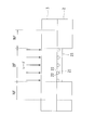
- FIG. 3 is a cross-sectional view of the first embodiment of the bonded structure according to the present invention.
- FIG. 4A is a diagram showing a modification of the first embodiment of the joint structure according to the present invention.
- FIG. 4B is a view showing another modification of the first embodiment of the joint structure according to the present invention.
- FIG. 4C is a diagram showing still another modification of the first embodiment of the joint structure according to the present invention.
- FIG. 4A is a diagram showing a modification of the first embodiment of the joint structure according to the present invention.
- FIG. 4B is a view showing another modification of the first embodiment of the joint structure according to the present invention.
- FIG. 4C is a diagram showing still another modification of the first embodiment of the joint structure according to the present
- FIG. 5 is a cross-sectional view of still another modification of the first embodiment of the bonded structure according to the present invention.
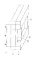
- FIG. 6 is a perspective view of still another modified example of the first embodiment of the bonded structure according to the present invention.
- FIG. 7 is a perspective view of still another modified example of the first embodiment of the bonded structure according to the present invention.
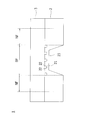
- FIG. 8 is a cross-sectional view of a second embodiment of the bonded structure according to the present invention.
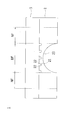
- FIG. 9A is a diagram showing a modification of the second embodiment of the joint structure according to the present invention.
- FIG. 9B is a diagram showing another modified example of the second embodiment of the joint structure according to the present invention.
- FIG. 9C is a diagram showing still another modification of the second embodiment of the joint structure according to the present invention.
- FIG. 9A is a diagram showing a modification of the second embodiment of the joint structure according to the present invention.
- FIG. 9B is a diagram showing another modified example of the second embodiment of the joint structure according
- FIG. 10 is a cross-sectional view of a third embodiment of the joint structure according to the present invention.
- FIG. 11 is a cross-sectional view of a modified example of the third embodiment of the bonded structure according to the present invention.
- FIG. 12 is a perspective view of another modification of the third embodiment of the joint structure according to the present invention.
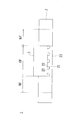
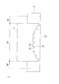
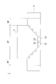
- FIG. 13 is an explanatory diagram schematically illustrating an example of the bonded structure according to the first embodiment.
- FIG. 14 is an explanatory diagram schematically illustrating an example of the bonded structure according to the third embodiment.
- FIG. 1 is an explanatory view for explaining an arrangement step in a method for manufacturing a bonded structure
- FIG. 2 is an explanatory view for explaining a bonding step in the method for manufacturing a bonded structure
- FIG. 3 is a first view of the bonded structure.
- 4A to 4C are cross-sectional views showing a modification of the first embodiment of the joint structure
- FIG. 5 is a cross-sectional view of another modification of the first embodiment of the joint structure.
- FIG. 6 is a perspective view of still another modified example of the first embodiment of the joined structure
- FIG. 7 is a perspective view of still another modified example of the first embodiment of the joined structure.
- the bonding structure 1 of the present embodiment is a bonding structure 1 in which a metal member 2 and a resin member 3 are bonded by a laser, and has a bonding region BF in which the metal member 2 and the resin member 3 are bonded. ing.
- Examples of the metal member 2 include iron metal, stainless steel metal, copper metal, aluminum metal, magnesium metal, and alloys thereof. Moreover, a metal molding may be sufficient and zinc die-casting, aluminum die-casting, powder metallurgy, etc. may be sufficient.
- a concave portion 21 having an opening on the surface of the metal member 2 is formed.
- the concave portion 21 is a substantially circular non-through hole when seen in a plan view, and a plurality of the concave portions 21 are formed on the surface of the metal member 2.
- the shape of a recessed part is not limited to a non-through-hole, For example, a groove shape may be sufficient if a cross section is a concave shape.
- the opening diameter of the concave portion 21 is preferably 30 ⁇ m or more and 100 ⁇ m or less. This is because, when the aperture diameter is less than 30 ⁇ m, the bonding laser irradiated in the bonding process described later is not sufficiently confined in the concave portion 21, and the conversion efficiency for converting the energy of the bonding laser into heat decreases. It is because there is a case to do. On the other hand, when the opening diameter exceeds 100 ⁇ m, the number of the concave portions 21 per unit area decreases, and the conversion efficiency for converting the energy of the laser for bonding into heat may decrease. Moreover, it is preferable that the depth of the recessed part 21 is 10 micrometers or more. This is because if the depth is less than 10 ⁇ m, the conversion efficiency for converting the energy of the laser for bonding into heat may decrease.
- the interval between the concave portions 21 (the distance between the center of the predetermined concave portion 21 and the center of the concave portion 21 adjacent to the predetermined concave portion 21) is preferably 200 ⁇ m or less. This is because if the interval between the concave portions 21 exceeds 200 ⁇ m, the number of the concave portions 21 per unit area decreases, and the conversion efficiency for converting the energy of the laser for bonding into heat may decrease. .
- An example of the lower limit of the interval between the concave portions 21 is a distance at which the concave portions 21 are not overlapped and crushed.
- interval of the recessed part 21 is equal intervals. This is because when the concave portions 21 are equidistant, the heat distribution when the bonding laser is irradiated is isotropic.
- the concave member 21 is filled with a resin member 3 to be described later, whereby the metal member 2 and the resin member 3 are joined.
- the concave portion 21 of the present embodiment is formed with a protruding portion 22 that protrudes inward.
- a thin portion 23 in which the thickness of the metal member 2 is reduced is provided in a region including the bonding region BF and the adjacent region NF adjacent to the bonding region BF (see FIG. 3).
- a hole is formed on the back surface of the metal member 2 to form a thin portion 23.
- the shape of the back surface processing of the metal member 2 is not limited to the hole shape, and may be a groove shape, for example. That is, any shape may be used as long as the metal member 2 is thin.
- the thin portion 23 is formed in the bonding region BF, but the concave portion 21 may be formed over the adjacent region NF adjacent to the bonding region BF.
- the adjacent region NF may reduce thermal diffusion in the laser irradiation direction (thickness direction of the metal member 2) even when the laser is applied to the bonding region BF of the metal member 2 in the bonding process described later.
- the area should be as large as possible.
- the shape of the thin portion 23 is not limited to the shape of FIG. 3, and as shown in FIG. 4A, the shape gradually thinned from the center of the bonding region BF toward the region end of the bonding region BF, As shown in FIG. 4B, the joining region BF on the back surface of the metal member 2 is processed into a trapezoidal shape in a cross-sectional view and thinned, or the joining region BF on the back surface of the metal member 2 is cross-sectionally shown in FIG. 4C.
- the shape may be thinned by processing by penetrating in a circular arc shape.
- the thin portion 23 may be provided with a heat insulating material 25 (see FIG. 5).
- An example of the heat insulating material 25 is a heat insulating material made of foamed resin.
- the thin portion 23 may be provided with a reinforcing portion 24 that reinforces the metal member 2 (see FIGS. 6 and 7).
- the reinforcing portion 24 may be disposed so as to be diagonally connected to each other in the groove formed on the back surface of the metal member 2, or as shown in FIG. A plurality of them may be arranged in parallel so as to connect each other.
- the strength of the metal member 2 can be increased.
- the resin member 3 is a thermoplastic resin or a thermosetting resin.
- the thermoplastic resin include PVC (polyvinyl chloride), PS (polystyrene), AS (acrylonitrile / styrene), ABS (acrylonitrile / butadiene). ⁇ Styrene), PMMA (polymethyl methacrylate), PE (polyethylene), PP (polypropylene), PC (polycarbonate), m-PPE (modified polyphenylene ether), PA6 (polyamide 6), PA66 (polyamide 66), POM (polyacetal) ), PET (polyethylene terephthalate), PBT (polybutylene terephthalate), PSF (polysulfone), PAR (polyarylate), PEI (polyetherimide), PPS (polyphenylene sulfide), PES (polyetherether) Hong), PEEK (polyetheretherketone), PAI (polyamideimide), LCP (liquid crystal
- TPE thermoplastic elastomer
- examples of TPE include TPO (olefin-based), TPS (styrene-based), TPEE (ester-based), TPU (urethane-based), TPA (nylon-based), And TPVC (vinyl chloride type) is mentioned.
- thermosetting resins examples include EP (epoxy), PUR (polyurethane), UF (urea formaldehyde), MF (melamine formaldehyde), PF (phenol formaldehyde), UP (unsaturated polyester), and SI (silicone). Is mentioned. Further, it may be FRP (fiber reinforced plastic).
- a filler may be added to the thermoplastic resin and the thermosetting resin.
- the filler include inorganic fillers (glass fibers, inorganic salts, etc.), metal fillers, organic fillers, and carbon fibers.
- the manufacturing method of the bonded structure 1 according to the present embodiment includes a thin portion forming step, a concave portion forming step, an arranging step, and a bonding step.
- a thin portion forming step a concave portion forming step
- an arranging step a bonding step.
- the thin part forming process is a thin part in which the thickness of the metal member 2 is reduced in the metal member 2 in a region including the bonding region BF and the adjacent region NF adjacent to the bonding region BF.
- 23 is a step of forming 23.
- a method of laser processing the metal member 2 or a method of forming a metal member 2 having the thin portion 23 by using a mold for forming the thin portion 23 in advance is not limited to these methods.
- the shape of the thin portion 23 is not limited to the shape of FIG. 3, and may be the shape shown in FIGS. 4A to 4C. Moreover, you may form the heat insulating material 25 in the thin part 23 (refer FIG. 5). Moreover, you may form the reinforcement part 24 which reinforces the metal member 2 in the thin part 23 (FIG.6 and FIG.7).
- the concave part formation process is a process of forming the concave part 21 having an opening in the bonding region BF on the surface of the metal member 2.
- the concave portion 21 is formed by a known method such as laser processing, blast processing, sandpaper processing, anodizing processing, electric discharge processing, etching processing, or press processing.
- a method for forming the concave portion 21 by laser processing will be described in detail.
- the type of processing laser that forms the concave portion 21 is preferably a laser capable of pulse oscillation, and can be selected from a fiber laser, a YAG laser, a YVO 4 laser, a semiconductor laser, a carbon dioxide gas laser, and an excimer laser. Then, a fiber laser, a YAG laser, a second harmonic of a YAG laser, a YVO 4 laser, and a semiconductor laser are preferable.
- the concave portion 21 is a substantially circular non-through hole as viewed in plan, and a plurality of the concave portions 21 are formed on the surface of the metal member 2.
- a fiber laser marker MXZ2000 or MX-Z2050 manufactured by OMRON As an example of an apparatus for forming the concave portion 21, there can be mentioned a fiber laser marker MXZ2000 or MX-Z2050 manufactured by OMRON. With this fiber laser marker, it is possible to irradiate a laser where one pulse is composed of a plurality of subpulses. For this reason, the energy of the laser is easily concentrated in the depth direction, which is suitable for forming the concave portion 21.
- the metal member 2 when the metal member 2 is irradiated with a laser, the metal member 2 is locally melted to advance the formation of the concave portion 21. At this time, since the laser is composed of a plurality of sub-pulses, the molten metal member 2 is not easily scattered and is easily deposited in the vicinity of the concave portion 21. When the formation of the concave portion 21 proceeds, the molten metal member 2 is deposited inside the concave portion 21, thereby forming a protruding portion 22 that protrudes inward on the inner peripheral surface of the concave portion 21. .
- one period of the subpulse is 15 ns or less. This is because when one period of the sub-pulse exceeds 15 ns, energy is easily diffused by heat conduction, and it becomes difficult to form the concave portion 21 having the protruding portion 22.
- one cycle of the subpulse is a total time of the irradiation time for one subpulse and the interval from the end of the irradiation of the subpulse to the start of the irradiation of the next subpulse.
- the number of subpulses of one pulse is preferably 2 or more and 50 or less. This is because if the number of subpulses exceeds 50, the output per unit of subpulses becomes small, and it becomes difficult to form the concave portion 21 having the protruding portions 22.
- positioning process is a process of arrange
- a laser absorption layer (not shown) may be provided on the surface of the metal member 2 or the surface of the resin member 3.
- a pigment-based or dye-based laser absorbing material having an absorptivity with respect to the wavelength of the laser for bonding can be appropriately selected and used. If comprised in this way, the improvement of the conversion efficiency which converts the energy of the laser for joining into heat can be aimed at.
- the thickness of the laser absorption layer is preferably 10 ⁇ m or less in order to ensure the filling property of the concave portion 21 of the metal member 2.
- a laser absorbing material may be blended in the resin member 3 as long as the resin member 3 satisfies the required laser transmittance.
- the bonding process is a process in which the resin member 3 is filled and bonded to the concave portion 21 of the metal member 2 by irradiating the bonding region BF of the metal member 2 with a laser from the resin member 3 side.
- the metal member 2 and the resin member 3 are pressed and brought into contact with each other, and then a bonding laser is irradiated toward the surface of the metal member 2.
- the laser irradiation may be performed from the resin member 3 side or from the metal member 2 side.
- the resin member 3 does not have laser transparency
- the laser is irradiated from the metal member 2 side.
- fiber laser, YAG laser, YVO 4 laser, a semiconductor laser, carbon dioxide laser, an excimer laser can be selected.
- the energy of the laser is converted into heat inside the metal member 2, and the surface temperature of the metal member 2 is increased.
- the resin member 3 in the vicinity of the surface of the metal member 2 is melted, and the concave portion 21 is filled with the resin member 3.
- the thin portion 23 is formed in the bonding region BF, even if the laser is irradiated to the bonding region BF of the metal member 2, heat in the laser irradiation direction (thickness direction of the metal member 2) is generated. Diffusion can be suppressed.
- the resin member 3 is solidified, whereby the bonded structure 1 in which the resin member 3 is bonded to the metal member 2 can be manufactured (see FIG. 3).
- the laser when irradiating the bonding area BF of the metal member 2 with a laser, the laser may be scanned in the bonding area BF, and the scanning may be performed a plurality of times along the same locus. In this case, since the laser scanning is performed a plurality of times along the same locus, the temperature of the metal member 2 rises, and the resin member 3 and the metal member 2 can be bonded more effectively.
- the metal is formed in the subsequent bonding step.
- the metal member 2 and the resin member 3 can be joined with less laser energy while suppressing thermal diffusion.
- FIG. 13 is an explanatory view schematically illustrating an example of a bonded structure.
- the metal member used in each example and each comparative example is made of SUS304, and has a length of 100 mm, a width of 29 mm, and a thickness of 3 mm.
- the resin member is a PMMA resin, and has a length of 100 mm, a width of 25 mm, and a thickness of 3 mm.
- region of a metal member and a resin member was set as width 20mm and length 20mm (refer FIG. 13).
- the laser used for joining the metal member and the resin member in the joining process is a semiconductor laser
- the wavelength is 808 nm
- the oscillation mode is continuous oscillation
- the focal diameter is 4 mm
- the scanning speed is 2 mm / sec
- the metal member and the resin The contact pressure with the member was set to 0.6 MPa.
- the joint strength was evaluated using an Instron electromechanical universal testing machine 5900. Specifically, the test was performed at a tensile speed of 5 mm / min in the shear direction to evaluate the bonding strength. The evaluation results are shown in Table 1.
- Comparative Example 1-1 In the joining structure of Comparative Example 1-1, the metal member is not provided with a thin portion, and the output of the semiconductor laser described above is set to 15 W in the joining step, and the metal member and the resin member are joined in the joining region. It was.
- the bonding strength of this bonded structure was 7.2 MPa.
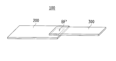
- Example 1-1 In the bonding structure 100 of Example 1-1, a hole having a length of 20 mm, a width of 20 mm, and a thickness of 2.5 mm is formed in the bonding region BF ′ on the back surface of the metal member 200 (that is, an area substantially equal to the bonding region BF ′).
- the output of the semiconductor laser described above was set to 15 W, and the metal member 200 and the resin member 300 were joined in the joining region BF ′.
- the bonding strength of this bonded structure 100 was 11.8 MPa.
- Example 1-2 In the bonding structure 100 of Example 1-2, the bonding region BF ′ on the back surface of the metal member 200 has a hole having a length of 20 mm, a width of 20 mm, and a thickness of 2.5 mm (that is, an area substantially equal to the bonding region BF ′).
- the output of the semiconductor laser described above was set to 20 W, and the metal member 200 and the resin member 300 were joined in the joining region BF ′.
- the bonding strength of this bonded structure 100 was 12.3 MPa.
- the bonding region BF ′ on the back surface of the metal member 200 has a hole having a length of 20 mm, a width of 20 mm, and a thickness of 2.5 mm (that is, an area substantially equal to the bonding region BF ′). Hole) to form a thin portion, a heat insulating material is provided in the hole, and in the bonding step, the output of the semiconductor laser described above is set to 15 W, and the metal member 200 and the resin member 300 are bonded to the bonding region BF ′. And joined.
- the bonding strength of this bonded structure 100 was 12.4 MPa.
- the bonding region BF ′ on the back surface of the metal member 200 has a hole having a length of 20 mm, a width of 20 mm, and a thickness of 2.5 mm (that is, an area substantially equal to the bonding region BF ′). Hole) is formed into a thin portion, and reinforcing portions formed so as to connect diagonal lines to each other are provided in the hole.
- the output of the above-described semiconductor laser is set to 15 W, and the metal The member 200 and the resin member 300 were joined at the joining region BF ′.
- the joint strength of this joint structure 100 was 11.5 MPa.
- the bonding region BF ′ on the back surface of the metal member 200 has a hole having a length of 20 mm, a width of 20 mm, and a thickness of 2.5 mm (that is, an area substantially equal to the bonding region BF ′). Hole) is formed into a thin portion, and reinforcing portions formed so as to connect diagonal lines to each other are provided in the hole.
- the output of the semiconductor laser described above is set to 20 W, and the metal The member 200 and the resin member 300 were joined at the joining region BF ′.
- the joint strength of this joint structure 100 was 11.3 MPa.
- the bonding strengths of the bonded structures of Comparative Examples 1-1 and 1-2 that do not include the thin portion are that of Examples 1-1 to 1-5 that include the thin portion. A result lower than the bonding strength of the bonded structure 100 was obtained.
- the bonding structure 100 corresponding to the present embodiment when the metal member 200 and the resin member 300 are bonded to each other by irradiating the bonding region BF ′ with a laser, a thin portion is formed in the bonding region BF ′. Therefore, thermal diffusion in the laser irradiation direction can be suppressed. Accordingly, the bonding strength between the metal member 200 and the resin member 300 can be improved while suppressing the laser output.
- FIG. 8 is a cross-sectional view of the second embodiment of the bonded structure
- FIGS. 9A to 9C are diagrams showing modifications of the second embodiment of the bonded structure.
- the bonded structure 1 of the present embodiment is provided with a thin portion 23 by processing the surface side of the metal member 2 (see FIG. 8).
- the thin portion 23 is formed in the bonding region BF.
- a concave portion 21 is formed in the thin portion 23, and the metal member 2 and the resin member 3 are joined by filling the concave portion 21 with the resin member 3.
- the protrusion part 22 which protrudes inside is formed in the concave-shaped part 21, the protrusion part 22 does not need to be formed.
- the shape of the thin portion 23 is not limited to the shape of FIG. 8, and as shown in FIG. 9A, the surface of the bonding region BF is raised so that the central portion is not flush with the surface of the bonding region BF.
- 9B a shape that is thinned as a convex shape in cross-sectional view, a shape that is thinned by processing the joint region BF on the surface of the metal member 2 through a trapezoidal shape in cross-sectional view, as shown in FIG.
- the bonding region BF on the surface of the metal member 2 may be formed in a thin shape by penetrating into a circular arc shape in a cross-sectional view.
- the resin member 3 has substantially the same size as the size of the bonding region BF (that is, the size enough to be accommodated in the groove corresponding to the thin portion 23).
- the resin member 3 may have the same size as the metal member 2, and the surface of the resin member 3 may be bulged to the extent that it is accommodated in the groove corresponding to the thin portion 23.
- the surface of the metal member 2 is processed into the thin part 23 by the thin part formation process.
- the shape of the thin portion 23 is not limited to the shape of FIG. 8, and may be the shape shown in FIGS. 9A to 9C.
- the recessed part 21 is formed in the thin part 23 of the metal member 2 by a recessed part formation process. At this time, when the laser is composed of a plurality of sub-pulses, the protruding portion 22 protruding inward can be formed on the inner peripheral surface of the concave portion 21.
- the resin member 3 is solidified, whereby the bonded structure 1 in which the resin member 3 is bonded to the metal member 2 can be manufactured.
- the thin portion 23 in which the thickness of the metal member 2 is reduced is formed also by the method for manufacturing the bonded structure 1 of the present embodiment, when the metal member 2 and the resin member 3 are bonded together.
- the metal member 2 and the resin member 3 can be joined with a small amount of laser energy.
- FIG. 10 is a cross-sectional view of the third embodiment of the joint structure
- FIG. 11 is a cross-sectional view of a modification of the third embodiment of the joint structure
- FIG. 12 is another view of the third embodiment of the joint structure. It is a perspective view of a modification.
- a thin portion 23 is formed by forming a slit on the back surface of the metal member 2 (see FIG. 10).
- two thin portions 23 are formed in a region including at least the adjacent region NF.
- the number of thin portions 23 may be one, or may be three or more.
- the thin portion 23 may be formed in the bonding region BF over a region including the adjacent region NF.
- the concave portion 21 is formed in the bonding region BF on the surface of the metal member 2. By filling the concave portion 21 with the resin member 3, the metal member 2 and the resin member 3 are joined. In addition, although the protrusion part 22 which protrudes inside is formed in the concave-shaped part 21, the protrusion part 22 does not need to be formed.
- the thin portion 23 may be provided with a heat insulating material 25 (see FIG. 11), or may be provided with a reinforcing portion 24 that reinforces the metal member 2 (see FIG. 12).
- the reinforcement part 24 may be arrange
- a slit is formed in the back surface of the metal member 2 by the thin part formation process, and it is set as the thin part 23.
- a heat insulating material 25 may be formed on the thin portion 23 (see FIG. 11), or a reinforcing portion 24 that reinforces the metal member 2 may be formed.
- the concave part 21 is formed in the joining area
- the resin member 3 in the vicinity of the surface of the metal member 2 is melted, and the resin member 3 is filled in the concave portion 21.
- the thin portion 23 is formed in a region including at least the adjacent region NF, thermal diffusion from the junction region BF to the outside via the thin portion 23 even if the junction region BF is irradiated with laser. Can be suppressed. That is, by forming the thin portion 23, the laser energy can be retained in the bonding region BF.
- the resin member 3 is solidified, whereby the bonded structure 1 in which the resin member 3 is bonded to the metal member 2 can be manufactured.
- the thin portion 23 in which the thickness of the metal member 2 is reduced is formed also by the method for manufacturing the bonded structure 1 of the present embodiment, when the metal member 2 and the resin member 3 are bonded together.
- the metal member 2 and the resin member 3 can be joined with a small amount of laser energy.
- FIG. 14 is an explanatory diagram schematically illustrating an example of the bonded structure according to the third embodiment.
- the metal member used in each example and each comparative example is made of SUS304, and has a length of 100 mm, a width of 29 mm, and a thickness of 3 mm.
- the resin member is a PMMA resin, and has a length of 100 mm, a width of 25 mm, and a thickness of 3 mm.
- region of a metal member and a resin member was set as width 20mm and length 20mm.
- the laser used for joining the metal member and the resin member in the joining process is a semiconductor laser
- the wavelength is 808 nm
- the oscillation mode is continuous oscillation
- the focal diameter is 4 mm
- the scanning speed is 2 mm / sec
- the metal member and the resin member was set to 0.6 MPa.
- the joint strength was evaluated using an Instron electromechanical universal testing machine 5900. Specifically, the test was performed at a tensile speed of 5 mm / min in the shear direction to evaluate the bonding strength. The evaluation results are shown in Table 2.
- Comparative Example 2-1 In the joining structure of Comparative Example 2-1, the metal member was not provided with a thin portion, and the output of the semiconductor laser was set to 15 W in the joining process, and the metal member and the resin member were joined in the joining region. It was.
- the bonding strength of this bonded structure was 5.6 MPa.
- Comparative Example 2-2 In the joining structure of Comparative Example 2-2, the metal member and the resin member are joined in the joining region in the joining step without setting the thin portion in the metal member and setting the output of the semiconductor laser described above to 20 W. It was.
- the bonding strength of this bonded structure was 7.2 MPa.
- Example 2-1 The bonding structure 100 of Example 2-1 is thin by forming a slit having a width of 0.2 mm and a depth of 2.5 mm in a region (adjacent region NF ′) surrounding the bonding region BF ′ on the back surface of the metal member 200.
- the output of the semiconductor laser described above was set to 15 W, and the metal member 200 and the resin member 300 were joined in the joining region BF ′.
- the bonding strength of this bonded structure 100 was 10.5 MPa.
- Example 2-2 The bonding structure 100 of Example 2-2 is thin by forming a slit having a width of 0.2 mm and a depth of 2.5 mm in a region (adjacent region NF ′) surrounding the bonding region BF ′ on the back surface of the metal member 200.
- the output of the semiconductor laser described above was set to 20 W, and the metal member 200 and the resin member 300 were joined in the joining region BF ′.
- the joint strength of this joint structure 100 was 11.2 MPa.
- Example 2-3 The bonding structure 100 of Example 2-3 is thin by forming a slit having a width of 0.2 mm and a depth of 2.5 mm in a region (adjacent region NF ′) surrounding the bonding region BF ′ on the back surface of the metal member 200.
- the output of the semiconductor laser described above was set to 15 W, and the metal member 200 and the resin member 300 were joined in the joining region BF ′.
- the bonding strength of this bonded structure 100 was 11.4 MPa.
- Example 2-4 The bonding structure 100 of Example 2-4 is thin by forming a slit having a width of 0.2 mm and a depth of 2.5 mm in a region (adjacent region NF ′) surrounding the bonding region BF ′ on the back surface of the metal member 200.
- the output of the semiconductor laser described above is set to 15 W, and the metal member 200 and the resin member 300 are joined at the joining region BF ′. It was made to join.
- the bonding strength of this bonded structure 100 was 10.4 MPa.
- Example 2-5 The bonding structure 100 of Example 2-5 is formed by forming a slit having a width of 0.2 mm and a depth of 2.5 mm in a region surrounding the bonding region BF ′ on the back surface of the metal member 200 (adjacent region NF ′).
- the output of the semiconductor laser described above is set to 20 W, and the metal member 200 and the resin member 300 are joined in the joining region BF ′. It was made to join.
- the bonding strength of this bonded structure 100 was 10.7 MPa.
- the thin portion is formed in the region including at least the adjacent region NF ′. Therefore, the metal member 200 is irradiated with the laser to the joining region BF ′.
- the resin member 300 and the resin member 300 are bonded, it is possible to suppress thermal diffusion from the bonding region BF ′ to the outside through the thin portion. Thereby, the energy of the laser is confined in the bonding region BF ′ with a small amount of laser energy, and the metal member 200 and the resin member 300 can be bonded.
Landscapes
- Engineering & Computer Science (AREA)
- Mechanical Engineering (AREA)
- Physics & Mathematics (AREA)
- Optics & Photonics (AREA)
- Health & Medical Sciences (AREA)
- Toxicology (AREA)
- Electromagnetism (AREA)
- Plasma & Fusion (AREA)
- Thermal Sciences (AREA)
- Lining Or Joining Of Plastics Or The Like (AREA)
- Laser Beam Processing (AREA)
Abstract
接合構造体は、金属部材と樹脂部材とが接合された接合領域を有する接合構造体であって、金属部材の接合領域には、金属部材の表面に開口を有する凹状部が形成されるとともに、金属部材の凹状部には、樹脂部材が充填されており、金属部材には、接合領域と、接合領域と隣接する隣接領域と、を包含する領域内に、金属部材の厚みが薄くされた薄厚部が設けられている。
Description
本発明は、金属部材と樹脂部材とが接合された接合領域を有する接合構造体及び接合構造体の製造方法に関する。
従来から、樹脂同士が接合された接合領域を有する接合構造体の製造方法として特許文献1が知られている。
特許文献1には、レーザ光を透過する透過性熱可塑性樹脂から構成される第1の部材と、レーザ光を吸収する吸収性熱可塑性樹脂から構成される第2の部材とを接触させ、レーザ光で接触面を溶融して接合する熱可塑性樹脂部材のレーザ溶着方法であって、第1の部材と第2の部材とを減圧雰囲気下で接触させ、第1の部材側から前記2つの部材の接触面に前記レーザ光を照射する熱可塑性樹脂部材のレーザ溶着方法が開示されている。
特許文献1によれば、レーザ光を透過する透過性熱可塑性樹脂から構成される第1の部材と、レーザ光を吸収する吸収性熱可塑性樹脂から構成される第2の部材とを接触させ、レーザ光を透過する第1の部材側からレーザ光を照射すると、レーザ光はレーザ光を透過しない第2の部材の表面でエネルギーが蓄積されて発熱する。レーザ光をさらに照射すると発熱量は大きくなり、接触面を通して第1の部材との接触面も同時に加熱され、2つの部材の接触面が溶融し、2つの部材が溶着される。
特許文献1の技術は、樹脂同士の接合に関する発明であるが、この発明を、樹脂部材と金属部材との接合に用いた場合は、以下に記載する課題が生じていた。
樹脂部材と金属部材とを減圧雰囲気下でレーザを照射して接合させた場合、減圧により樹脂側への熱拡散が生じにくいことに加え、熱伝導度の違いから金属部材側への熱拡散が圧倒的に大きいので、樹脂部材の熱溶融が生じにくかった。そのため、樹脂部材の熱溶融を生じさせて、樹脂部材と金属部材とを接合させるためには、レーザの照射エネルギーを上げる必要があった。このように、レーザの照射エネルギーを上げることは、省エネルギー化の観点から好ましくない。
本発明は、かかる点に鑑みてなされたものであり、その目的とするところは、金属部材と樹脂部材とのレーザ接合時に照射されたレーザエネルギーが小さい場合でも、金属部材の熱拡散を抑制して樹脂部材の熱溶融性を高め、金属部材と樹脂部材との接合性が良好な接合構造体及びこの接合構造体の製造方法の提供を目的とする。
上記目的を達するために、本発明は次のとおりの構成としている。
本発明に係る接合構造体は、金属部材と樹脂部材とが接合された接合領域を有する接合構造体であって、前記金属部材の前記接合領域には、当該金属部材の表面に開口を有する凹状部が形成されるとともに、前記金属部材の凹状部には、前記樹脂部材が充填されており、前記金属部材には、前記接合領域と、該接合領域と隣接する隣接領域と、を包含する領域内に、前記金属部材の厚みが薄くされた薄厚部が設けられていることを特徴とする。
また、上記接合構造体であって、前記薄厚部は、前記接合領域内に形成されていてもよい。
また、上記接合構造体であって、前記薄厚部は、少なくとも前記隣接領域を含む領域内に形成されていてもよい。
また、上記接合構造体であって、前記薄厚部には、断熱材が備えられていてもよい。
また、上記接合構造体であって、前記薄厚部には、前記金属部材を補強する補強部が備えられていてもよい。
また、上記接合構造体であって、前記凹状部の内周面には、内側に突出する突出部が形成されていてもよい。
また、本発明に係る接合構造体の製造方法は、金属部材と樹脂部材とが接合された接合領域を有する接合構造体の製造方法であって、前記金属部材において、前記接合領域と、該接合領域と隣接する隣接領域と、を包含する領域内に、前記金属部材の厚みが薄くされた薄厚部を形成する薄厚部形成工程と、前記金属部材の表面の前記接合領域に、開口を有する凹状部を形成する凹状部形成工程と、前記金属部材の表面と前記樹脂部材とを隣接配置する配置工程と、前記樹脂部材側から前記金属部材の接合領域にレーザを照射することにより、前記金属部材の前記凹状部に前記樹脂部材を充填して接合させる接合工程と、を備えることを特徴とする。
また、上記接合構造体の製造方法であって、前記接合工程では、前記金属部材の接合領域にレーザを照射する際に、前記接合領域内においてレーザを走査させるとともに、前記走査を同一軌跡で複数回行うこととしてもよい。
また、上記接合構造体の製造方法であって、前記凹状部形成工程では、1パルスが複数のサブパルスで構成されるレーザを照射することにより、前記凹状部を形成してもよい。
本発明によれば、金属部材と樹脂部材とのレーザ接合時に照射されたレーザエネルギーが小さい場合でも、金属部材の熱拡散を抑制して樹脂部材の熱溶融性を高め、金属部材と樹脂部材との接合性が良好な接合構造体及びこの接合構造体の製造方法を提供できる。
(第1実施形態)
以下、本発明の第1実施形態の接合構造体1及びこの接合構造体1の製造方法について図1~7を参照しながら説明する。
以下、本発明の第1実施形態の接合構造体1及びこの接合構造体1の製造方法について図1~7を参照しながら説明する。
図1は、接合構造体の製造方法において、配置工程を説明する説明図、図2は、接合構造体の製造方法において、接合工程を説明する説明図、図3は、接合構造体の第1実施形態の断面図、図4A~4Cは、それぞれ、接合構造体の第1実施形態の変形例を示す断面図、図5は、接合構造体の第1実施形態の他の変形例の断面図、図6は、接合構造体の第1実施形態のさらに他の変形例の斜視図、図7は、接合構造体の第1実施形態のさらに他の変形例の斜視図である。
-接合構造体の構成-
まず、本発明の第1実施形態の接合構造体1について説明する。
まず、本発明の第1実施形態の接合構造体1について説明する。
本実施形態の接合構造体1は、金属部材2と樹脂部材3とがレーザによって接合された接合構造体1であって、金属部材2と樹脂部材3とが接合された接合領域BFを有している。
金属部材2は、鉄系金属、ステンレス系金属、銅系金属、アルミ系金属、マグネシウム系金属、および、それらの合金が挙げられる。また、金属成型体であってもよく、亜鉛ダイカスト、アルミダイカスト、粉末冶金などであってもよい。
金属部材2の接合領域BFには、金属部材2の表面に開口を有する凹状部21が形成される。凹状部21は、平面的に見てほぼ円形の非貫通孔であり、金属部材2の表面に複数形成されている。なお、凹状部の形状は、非貫通孔に限定されず、断面が凹形状であれば、例えば、溝状であってもよい。
凹状部21の開口径は、30μm以上、100μm以下が好ましい。これは、開口径が30μmを下回ると、後述する接合工程において照射された接合用のレーザが凹状部21内に十分に閉じ込められず、接合用のレーザのエネルギーを熱に変換する変換効率が低下する場合があるためである。一方、開口径が100μmを上回ると、単位面積あたりの凹状部21の数が減少して、接合用のレーザのエネルギーを熱に変換する変換効率が低下する場合があるためである。また、凹状部21の深さは、10μm以上であることが好ましい。これは、深さが10μmを下回ると、接合用のレーザのエネルギーを熱に変換する変換効率が低下する場合があるためである。
また、凹状部21の間隔(所定の凹状部21の中心と、所定の凹状部21と隣接する凹状部21の中心との距離)は、200μm以下であることが好ましい。これは、凹状部21の間隔が200μmを上回ると、単位面積あたりの凹状部21の数が減少して、接合用のレーザのエネルギーを熱に変換する変換効率が低下する場合があるためである。なお、凹状部21の間隔の下限の一例としては、凹状部21が重畳して潰れない距離である。また、凹状部21の間隔は等間隔であることが好ましい。これは、凹状部21が等間隔であると、接合用のレーザが照射される際の熱の分布が等方的になるためである。
凹状部21には、後述する樹脂部材3が充填されることにより、金属部材2と樹脂部材3とが接合される。ここで、本実施形態の凹状部21には、内側に突出する突出部22が形成されている。このように凹状部21の内周面に、内側に突出する突出部22が形成されている場合は、凹状部21に樹脂部材3が充填されると、突出部22によるアンカー効果によって金属部材2と樹脂部材3との接合強度を高めることができる。なお、凹状部21に突出部22が形成されていなくてもよい。
金属部材2のうちの、接合領域BFと、接合領域BFと隣接する隣接領域NFと、を包含する領域内には、金属部材2の厚みが薄くされた薄厚部23が設けられている(図3参照)。図示例では、金属部材2の裏面に孔が形成されて薄厚部23とされている。なお、金属部材2の裏面加工の形状は、孔形状に限られず、例えば、溝形状でもよい。すなわち、金属部材2が薄厚とされていればどのような形状でもよい。
また、図示例では、薄厚部23は、接合領域BF内に形成されているが、凹状部21が接合領域BFと隣接する隣接領域NFに亘って形成されていてもよい。ここで、隣接領域NFは、後述する接合工程において、レーザを金属部材2の接合領域BFに照射しても、レーザの照射方向(金属部材2の厚み方向)への熱拡散を少なくすることができる程度の領域とする。
なお、薄厚部23の形状は、図3の形状に限定されるものではなく、図4Aのように、接合領域BFの中央から接合領域BFの領域端に向けて徐々に薄厚にした形状や、図4Bのように、金属部材2の裏面の接合領域BFを断面視で台形状に刳り貫いて加工して薄厚にした形状や、図4Cのように金属部材2の裏面の接合領域BFを断面視で円弧状に刳り貫いて加工して薄厚にした形状であってもよい。
また、薄厚部23には、断熱材25が備えられていてもよい(図5参照)。断熱材25の一例としては、発泡樹脂からなる断熱材が挙げられる。このように、薄厚部23に断熱材25が備えられている場合は、後述する接合構造体1の製造方法における接合工程において、接合領域BFにレーザを照射させて金属部材2と樹脂部材3とを接合させた場合、接合領域BF内に熱を閉じ込める効果を高めることができる。
また、薄厚部23には、金属部材2を補強する補強部24を備えていてもよい(図6及び図7参照)。補強部24は、図6に示すように、金属部材2の裏面に形成された溝内に互いに対角を結ぶように配置されていてもよいし、図7に示すように、溝内の間隙を結ぶように平行に複数配置されていてもよい。このように、薄厚部23に金属部材2を補強する補強部24が備えられている場合は、金属部材2の強度を高めることができる。
樹脂部材3は、熱可塑性樹脂、または、熱硬化性樹脂であり、熱可塑性樹脂の一例としては、PVC(ポリ塩化ビニル)、PS(ポリスチレン)、AS(アクリロニトリル・スチレン)、ABS(アクリロニトリル・ブタジエン・スチレン)、PMMA(ポリメチルメタクリレート)、PE(ポリエチレン)、PP(ポリプロピレン)、PC(ポリカーボネート)、m-PPE(変性ポリフェニレンエーテル)、PA6(ポリアミド6)、PA66(ポリアミド66)、POM(ポリアセタール)、PET(ポリエチレンテレフタレート)、PBT(ポリブチレンテレフタレート)、PSF(ポリサルホン)、PAR(ポリアリレート)、PEI(ポリエーテルイミド)、PPS(ポリフェニレンサルファイド)、PES(ポリエーテルサルホン)、PEEK(ポリエーテルエーテルケトン)、PAI(ポリアミドイミド)、LCP(液晶ポリマー)、PVDC(ポリ塩化ビニリデン)、PTFE(ポリテトラフルオロエチレン)、PCTFE(ポリクロロトリフルオロエチレン)、および、PVDF(ポリフッ化ビニリデン)が挙げられる。また、TPE(熱可塑性エラストマ)であってもよく、TPEの一例としては、TPO(オレフィン系)、TPS(スチレン系)、TPEE(エステル系)、TPU(ウレタン系)、TPA(ナイロン系)、および、TPVC(塩化ビニル系)が挙げられる。
熱硬化性樹脂の一例としては、EP(エポキシ)、PUR(ポリウレタン)、UF(ユリアホルムアルデヒド)、MF(メラミンホルムアルデヒド)、PF(フェノールホルムアルデヒド)、UP(不飽和ポリエステル)、および、SI(シリコーン)が挙げられる。また、FRP(繊維強化プラスチック)であってもよい。
なお、熱可塑性樹脂および熱硬化性樹脂には、充填剤が添加されていてもよい。充填剤の一例としては、無機系充填剤(ガラス繊維、無機塩類など)、金属系充填剤、有機系充填剤、および、炭素繊維などが挙げられる。
-接合構造体の製造方法-
次に、本実施形態に係る接合構造体1の製造方法について説明する。
次に、本実施形態に係る接合構造体1の製造方法について説明する。
本実施形態に係る接合構造体1の製造方法は、薄厚部形成工程と、凹状部形成工程と、配置工程と、接合工程と、を備える。以下、各工程について説明するが、本実施形態に係る接合構造体の製造方法の工程の順番は、説明する順番に限定されるものではない。
・薄厚部形成工程
薄厚部形成工程は、金属部材2において、接合領域BFと、接合領域BFと隣接する隣接領域NFと、を包含する領域内に、金属部材2の厚みが薄くされた薄厚部23を形成する工程である。
薄厚部形成工程は、金属部材2において、接合領域BFと、接合領域BFと隣接する隣接領域NFと、を包含する領域内に、金属部材2の厚みが薄くされた薄厚部23を形成する工程である。
薄厚部23の形成には、金属部材2をレーザ加工する方法や、予め、薄厚部23を形成するための金型を用いて、当該金型によって薄厚部23を有する金属部材2を形成する方法等が挙げられるが、これらの方法に限定されるものではない。
なお、薄厚部23の形状は、図3の形状に限定されるものではなく、図4A~図4Cに示した形状であってもよい。また、薄厚部23には、断熱材25を形成してもよい(図5参照)。また、薄厚部23には、金属部材2を補強する補強部24を形成してもよい(図6及び図7)。
・凹状部形成工程
凹状部形成工程は、金属部材2の表面の接合領域BFに、開口を有する凹状部21を形成する工程である。
凹状部形成工程は、金属部材2の表面の接合領域BFに、開口を有する凹状部21を形成する工程である。
凹状部21は、レーザ加工処理、ブラスト処理、サンドペーパ処理、陽極酸化処理、放電加工処理、エッチング処理、およびプレス加工処理等の公知の方法で形成される。本実施形態では、レーザ加工処理によって凹状部21を形成する方法について詳述する。
凹状部21を形成する加工用レーザの種類としては、パルス発振が可能なものが好ましく、ファイバレーザ、YAGレーザ、YVO4レーザ、半導体レーザ、炭酸ガスレーザ、エキシマレーザが選択でき、レーザの波長を考慮すると、ファイバレーザ、YAGレーザ、YAGレーザの第2高調波、YVO4レーザ、半導体レーザが好ましい。凹状部21は、平面的に見てほぼ円形の非貫通孔であり、金属部材2の表面に複数形成される。
凹状部21を形成する装置の一例としては、オムロン製のファイバレーザマーカMXZ2000またはMX-Z2050を挙げることができる。このファイバレーザマーカでは、1パルスが複数のサブパルスで構成されるレーザを照射することが可能である。このため、レーザのエネルギーを深さ方向に集中させやすいので、凹状部21を形成するのに好適である。
具体的には、金属部材2にレーザが照射されると、金属部材2が局部的に溶融されることにより凹状部21の形成が進行する。このとき、レーザが複数のサブパルスで構成されているため、溶融された金属部材2が飛散されにくく、凹状部21の近傍に堆積されやすい。そして、凹状部21の形成が進行すると、溶融された金属部材2が凹状部21の内部に堆積されることにより、凹状部21の内周面に、内側に突出する突出部22が形成される。
なお、上記ファイバレーザマーカによる加工条件としては、サブパルスの1周期が15ns以下であることが好ましい。これは、サブパルスの1周期が15nsを超えると、熱伝導によりエネルギーが拡散しやすくなり、突出部22を有する凹状部21を形成しにくくなるためである。なお、サブパルスの1周期は、サブパルスの1回分の照射時間と、そのサブパルスの照射が終了されてから次回のサブパルスの照射が開始されるまでの間隔との合計時間である。
また、上記ファイバレーザマーカによる加工条件としては、1パルスのサブパルス数は、2以上50以下であることが好ましい。これは、サブパルス数が50を超えると、サブパルスの単位あたりの出力が小さくなり、突出部22を有する凹状部21を形成しにくくなるためである。
なお、凹状部形成工程は、コストの観点から薄厚部形成工程後に行うことが好ましいが、凹状部形成工程後に上述した薄厚部形成工程を行ってもよい。
・配置工程
配置工程は、金属部材2の表面と樹脂部材3とを隣接配置する工程である(図1参照)。隣接配置する際に、金属部材2及び樹脂部材3を加圧することにより、後述する接合工程によって接合しやすくすることができる。
配置工程は、金属部材2の表面と樹脂部材3とを隣接配置する工程である(図1参照)。隣接配置する際に、金属部材2及び樹脂部材3を加圧することにより、後述する接合工程によって接合しやすくすることができる。
なお、金属部材2および樹脂部材3が隣接配置されたときに、金属部材2の表面または樹脂部材3の表面にレーザ吸収層(図示省略)が設けられていてもよい。このレーザ吸収層としては、接合用のレーザの波長に対して吸収性を有する顔料系または染料系のレーザ吸収材などを適宜選択して用いることができる。このように構成すれば、接合用のレーザのエネルギーを熱に変換する変換効率の向上を図ることができる。なお、レーザ吸収層の厚みは、金属部材2の凹状部21への充填性を確保するために10μm以下が好ましい。また、樹脂部材3が要求されるレーザの透過性を満たす範囲内において、樹脂部材3にレーザ吸収材が配合されていてもよい。
・接合工程
接合工程は、樹脂部材3側から金属部材2の接合領域BFにレーザを照射することにより、金属部材2の凹状部21に樹脂部材3を充填して接合させる工程である。
接合工程は、樹脂部材3側から金属部材2の接合領域BFにレーザを照射することにより、金属部材2の凹状部21に樹脂部材3を充填して接合させる工程である。
具体的には、配置工程において、金属部材2と樹脂部材3とを加圧して接触させた後、接合用のレーザを金属部材2の表面に向けて照射する。
ここで、レーザ照射は、樹脂部材3がレーザ透過性を有する場合は、樹脂部材3側からレーザを照射してもよいし、金属部材2側からレーザを照射してもよい。一方で、樹脂部材3がレーザ透過性を有しない場合は、金属部材2側からレーザを照射する。なお、接合用のレーザの種類としては、ファイバレーザ、YAGレーザ、YVO4レーザ、半導体レーザ、炭酸ガスレーザ、エキシマレーザが選択できる。
レーザを金属部材2の接合領域BFに照射することにより、レーザのエネルギーが金属部材2の内部で熱に変換され、金属部材2の表面の温度が高くなる。これにより、金属部材2の表面近傍の樹脂部材3が溶融され、その樹脂部材3が凹状部21に充填される。本実施形態では、薄厚部23が接合領域BF内に形成されているので、レーザを金属部材2の接合領域BFに照射しても、レーザの照射方向(金属部材2の厚み方向)への熱拡散を抑制することができる。
その後、樹脂部材3が固化されることにより、樹脂部材3が金属部材2に接合された接合構造体1を製造できる(図3参照)。
ここで、金属部材2の接合領域BFにレーザを照射する際に、接合領域BF内においてレーザを走査させるとともに、前記走査を同一軌跡で複数回行ってもよい。この場合は、レーザの走査を同一軌跡で複数回行われるため、金属部材2の温度が上昇し、より効果的に樹脂部材3と金属部材2とを接合することができる。
以上、説明したとおり、本実施形態の接合構造体1の製造方法によれば、金属部材2の厚みが薄くされた薄厚部23を形成する薄厚部形成工程を備えるため、その後の接合工程において金属部材2と樹脂部材3とを接合させる際に、熱拡散を抑制して少ないレーザエネルギーで金属部材2と樹脂部材3とを接合させることができる。
-接合構造体の実験例-
次に、上記した第1実施形態の効果を確認するために行った実験例について図13を参照しながら説明する。図13は、接合構造体の実施例を模式的に説明した説明図である。
次に、上記した第1実施形態の効果を確認するために行った実験例について図13を参照しながら説明する。図13は、接合構造体の実施例を模式的に説明した説明図である。
この実験例では、第1実施形態に対応する接合構造体の実施例1-1~1-5並びに比較例1-1及び1-2による接合構造体を作製した。
なお、各実施例及び各比較例に用いた金属部材は、材質がSUS304であり、長さ100mm、幅29mm、厚み3mmである。また、樹脂部材は、PMMA樹脂であり、長さ100mm、幅25mm、厚み3mmである。また、金属部材と樹脂部材との接合領域は、幅20mm、長さ20mmと設定した(図13参照)。
さらに、接合工程における金属部材と樹脂部材との接合に用いたレーザは、半導体レーザであり、波長が808nm、発振モードは連続発振、焦点径は4mm、走査速度は2mm/sec、金属部材と樹脂部材との密着圧力は0.6MPaと設定した。
接合強度の評価は、インストロン製の電気機械式万能試験機5900を用いて行った。具体的には、せん断方向に引張速度5mm/minで試験を行い、接合強度を評価した。評価結果を表1に示す。

[比較例1-1]
比較例1-1の接合構造体は、金属部材に薄厚部を設けずに、接合工程において、上述した半導体レーザの出力を15Wと設定して、金属部材と樹脂部材とを接合領域で接合させた。
比較例1-1の接合構造体は、金属部材に薄厚部を設けずに、接合工程において、上述した半導体レーザの出力を15Wと設定して、金属部材と樹脂部材とを接合領域で接合させた。
この接合構造体の接合強度は5.6MPaであった。
[比較例1-2]
比較例1-2の接合構造体は、金属部材に薄厚部を設けずに、接合工程において、上述した半導体レーザの出力を20Wと設定して、金属部材と樹脂部材とを接合領域で接合させた。
[比較例1-2]
比較例1-2の接合構造体は、金属部材に薄厚部を設けずに、接合工程において、上述した半導体レーザの出力を20Wと設定して、金属部材と樹脂部材とを接合領域で接合させた。
この接合構造体の接合強度は7.2MPaであった。
[実施例1-1]
実施例1-1の接合構造体100は、金属部材200の裏面の接合領域BF´に、長さ20mm、幅20mm、厚み2.5mmの孔(すなわち、接合領域BF´と略等しい面積を有する孔)を形成して薄厚部とし、接合工程において、上述した半導体レーザの出力を15Wと設定して、金属部材200と樹脂部材300とを接合領域BF´で接合させた。
実施例1-1の接合構造体100は、金属部材200の裏面の接合領域BF´に、長さ20mm、幅20mm、厚み2.5mmの孔(すなわち、接合領域BF´と略等しい面積を有する孔)を形成して薄厚部とし、接合工程において、上述した半導体レーザの出力を15Wと設定して、金属部材200と樹脂部材300とを接合領域BF´で接合させた。
この接合構造体100の接合強度は11.8MPaであった。
[実施例1-2]
実施例1-2の接合構造体100は、金属部材200の裏面の接合領域BF´に、長さ20mm、幅20mm、厚み2.5mmの孔(すなわち、接合領域BF´と略等しい面積を有する孔)を形成して薄厚部とし、接合工程において、上述した半導体レーザの出力を20Wと設定して、金属部材200と樹脂部材300とを接合領域BF´で接合させた。
実施例1-2の接合構造体100は、金属部材200の裏面の接合領域BF´に、長さ20mm、幅20mm、厚み2.5mmの孔(すなわち、接合領域BF´と略等しい面積を有する孔)を形成して薄厚部とし、接合工程において、上述した半導体レーザの出力を20Wと設定して、金属部材200と樹脂部材300とを接合領域BF´で接合させた。
この接合構造体100の接合強度は12.3MPaであった。
[実施例1-3]
実施例1-3の接合構造体100は、金属部材200の裏面の接合領域BF´に、長さ20mm、幅20mm、厚み2.5mmの孔(すなわち、接合領域BF´と略等しい面積を有する孔)を形成して薄厚部とするとともに、孔内に断熱材を設け、接合工程において、上述した半導体レーザの出力を15Wと設定して、金属部材200と樹脂部材300とを接合領域BF´で接合させた。
実施例1-3の接合構造体100は、金属部材200の裏面の接合領域BF´に、長さ20mm、幅20mm、厚み2.5mmの孔(すなわち、接合領域BF´と略等しい面積を有する孔)を形成して薄厚部とするとともに、孔内に断熱材を設け、接合工程において、上述した半導体レーザの出力を15Wと設定して、金属部材200と樹脂部材300とを接合領域BF´で接合させた。
この接合構造体100の接合強度は12.4MPaであった。
[実施例1-4]
実施例1-4の接合構造体100は、金属部材200の裏面の接合領域BF´に、長さ20mm、幅20mm、厚み2.5mmの孔(すなわち、接合領域BF´と略等しい面積を有する孔)を形成して薄厚部とするとともに、孔内に互いに対角線を結ぶように形成された補強部が備えられており、接合工程において、上述した半導体レーザの出力を15Wと設定して、金属部材200と樹脂部材300とを接合領域BF´で接合させた。
実施例1-4の接合構造体100は、金属部材200の裏面の接合領域BF´に、長さ20mm、幅20mm、厚み2.5mmの孔(すなわち、接合領域BF´と略等しい面積を有する孔)を形成して薄厚部とするとともに、孔内に互いに対角線を結ぶように形成された補強部が備えられており、接合工程において、上述した半導体レーザの出力を15Wと設定して、金属部材200と樹脂部材300とを接合領域BF´で接合させた。
この接合構造体100の接合強度は11.5MPaであった。
[実施例1-5]
実施例1-5の接合構造体100は、金属部材200の裏面の接合領域BF´に、長さ20mm、幅20mm、厚み2.5mmの孔(すなわち、接合領域BF´と略等しい面積を有する孔)を形成して薄厚部とするとともに、孔内に互いに対角線を結ぶように形成された補強部が備えられており、接合工程において、上述した半導体レーザの出力を20Wと設定して、金属部材200と樹脂部材300とを接合領域BF´で接合させた。
実施例1-5の接合構造体100は、金属部材200の裏面の接合領域BF´に、長さ20mm、幅20mm、厚み2.5mmの孔(すなわち、接合領域BF´と略等しい面積を有する孔)を形成して薄厚部とするとともに、孔内に互いに対角線を結ぶように形成された補強部が備えられており、接合工程において、上述した半導体レーザの出力を20Wと設定して、金属部材200と樹脂部材300とを接合領域BF´で接合させた。
この接合構造体100の接合強度は11.3MPaであった。
以上の接合強度の評価結果から、薄厚部が備えられていない比較例1-1及び1-2の接合構造体の接合強度は、薄厚部が備えられた実施例1-1~1-5の接合構造体100の接合強度よりも低い結果が得られた。
これにより、本実施形態に対応する接合構造体100によれば、接合領域BF´にレーザを照射させて金属部材200と樹脂部材300とを接合させると、薄厚部が接合領域BF´内に形成されているので、レーザの照射方向への熱拡散を抑制することができる。従って、レーザ出力を抑制しながら金属部材200と樹脂部材300との接合強度を向上させることができる。
(第2実施形態)
以下、本発明の第2実施形態の接合構造体1及びこの接合構造体1の製造方法にについて図8及び9を参照しながら説明する。図8は、接合構造体の第2実施形態の断面図、図9A~9Cは、それぞれ、接合構造体の第2実施形態の変形例を示す図である。
以下、本発明の第2実施形態の接合構造体1及びこの接合構造体1の製造方法にについて図8及び9を参照しながら説明する。図8は、接合構造体の第2実施形態の断面図、図9A~9Cは、それぞれ、接合構造体の第2実施形態の変形例を示す図である。
なお、本実施形態は、接合構造体1の薄厚部23に樹脂部材3が収容されて接合されている点が異なるだけであるので、以下、その相違点についてのみ説明し、同一の構成要素については、同一符号を付してその説明を省略する。
-接合構造体の構成-
まず、本発明の第2実施形態の接合構造体1について説明する。
まず、本発明の第2実施形態の接合構造体1について説明する。
本実施形態の接合構造体1は、金属部材2の表面側を加工して薄厚部23が設けられている(図8参照)。図示例では、薄厚部23は、接合領域BF内に形成されている。
薄厚部23には、凹状部21が形成されており、この凹状部21に樹脂部材3が充填されることにより、金属部材2と樹脂部材3とが接合される。なお、凹状部21には、内側に突出する突出部22が形成されているが、突出部22が形成されていなくてもよい。
なお、薄厚部23の形状は、図8の形状に限定されるものではなく、図9Aのように、接合領域BFの表面において、中央部が接合領域BFの表面と面一とならない程度に隆起させて断面視凸形状として薄厚にした形状や、図9Bのように、金属部材2の表面の接合領域BFを断面視で台形状に刳り貫いて加工して薄厚にした形状や、図9Cのように、金属部材2の表面の接合領域BFを断面視で円弧状に刳り貫いて加工して薄厚にした形状であってもよい。
樹脂部材3は、図8及び9A~9Cに示すとおり、接合領域BFの大きさと略同一の大きさ(つまり、薄厚部23に相当する溝内に収容される程度の大きさ)とされているが、この例に限られない。すなわち、樹脂部材3を金属部材2と同程度の大きさとし、樹脂部材3の表面が、薄厚部23に相当する溝内に収容される程度に膨出されていてもよい。
-接合構造体の製造方法-
次に、本実施形態に係る接合構造体1の製造方法について説明する。
次に、本実施形態に係る接合構造体1の製造方法について説明する。
・薄厚部形成工程
薄厚部形成工程により、金属部材2の表面を加工して薄厚部23とする。なお、薄厚部23の形状は、図8の形状に限定されるものではなく、図9A~9Cに示した形状であってもよい。
薄厚部形成工程により、金属部材2の表面を加工して薄厚部23とする。なお、薄厚部23の形状は、図8の形状に限定されるものではなく、図9A~9Cに示した形状であってもよい。
・凹状部形成工程
凹状部形成工により、金属部材2の薄厚部23に凹状部21を形成する。このとき、レーザが複数のサブパルスで構成されている場合は、凹状部21の内周面に、内側に突出する突出部22を形成できる。
凹状部形成工により、金属部材2の薄厚部23に凹状部21を形成する。このとき、レーザが複数のサブパルスで構成されている場合は、凹状部21の内周面に、内側に突出する突出部22を形成できる。
・配置工程及び接合工程
配置工程により、金属部材2の表面と樹脂部材3とを隣接配置する。そして、金属部材2と樹脂部材3とを加圧して接触させた後、接合用のレーザを金属部材2の表面に向けて照射する。これにより、金属部材2の表面近傍の樹脂部材3が溶融され、その樹脂部材3が凹状部21に充填される。
配置工程により、金属部材2の表面と樹脂部材3とを隣接配置する。そして、金属部材2と樹脂部材3とを加圧して接触させた後、接合用のレーザを金属部材2の表面に向けて照射する。これにより、金属部材2の表面近傍の樹脂部材3が溶融され、その樹脂部材3が凹状部21に充填される。
その後、樹脂部材3が固化されることにより、樹脂部材3が金属部材2に接合された接合構造体1を製造できる。
以上、説明したとおり、本実施形態の接合構造体1の製造方法によっても、金属部材2の厚みが薄くされた薄厚部23が形成されるため、金属部材2と樹脂部材3とを接合させる際に、少ないレーザエネルギーで金属部材2と樹脂部材3とを接合させることができる。
(第3実施形態)
以下、本発明の第3実施形態の接合構造体及びこの接合構造体の製造方法にについて図10~12を参照しながら説明する。
以下、本発明の第3実施形態の接合構造体及びこの接合構造体の製造方法にについて図10~12を参照しながら説明する。
図10は、接合構造体の第3実施形態の断面図、図11は、接合構造体の第3実施形態の変形例の断面図、図12は、接合構造体の第3実施形態の他の変形例の斜視図である。
なお、本実施形態は、接合構造体1の薄厚部23の構造が異なるだけであるので、以下、その相違点についてのみ説明し、同一の構成要素については、同一符号を付してその説明を省略する。
-接合構造体の構成-
まず、本発明の第3実施形態の接合構造体1について説明する。
まず、本発明の第3実施形態の接合構造体1について説明する。
本実施形態の接合構造体1は、金属部材2の裏面にスリットを形成して薄厚部23が形成されている(図10参照)。
薄厚部23は、図示例では、少なくとも隣接領域NFを含む領域内に2つ形成されている。なお、薄厚部23の数は、1つでもよいし、3つ以上であってもよい。また、薄厚部23は、隣接領域NFを含む領域に亘って接合領域BF内に形成されていてもよい。
凹状部21は、金属部材2の表面における接合領域BFに形成されている。この凹状部21に樹脂部材3が充填されることにより、金属部材2と樹脂部材3とが接合される。なお、凹状部21には、内側に突出する突出部22が形成されているが、突出部22が形成されていなくてもよい。
なお、薄厚部23には、断熱材25が備えられていてもよいし(図11参照)、金属部材2を補強する補強部24が備えられていてもよい(図12参照)。また、補強部24は、スリットの間隙を結ぶように平行に配置されていてもよいし、スリット内に対角状に配置されていてもよい。
-接合構造体の製造方法-
次に、本実施形態に係る接合構造体1の製造方法について説明する。
次に、本実施形態に係る接合構造体1の製造方法について説明する。
・薄厚部形成工程
薄厚部形成工程により、金属部材2の裏面にスリットを形成して薄厚部23とする。なお、薄厚部23には、断熱材25を形成してもよいし(図11参照)、金属部材2を補強する補強部24を形成してもよい。
薄厚部形成工程により、金属部材2の裏面にスリットを形成して薄厚部23とする。なお、薄厚部23には、断熱材25を形成してもよいし(図11参照)、金属部材2を補強する補強部24を形成してもよい。
・凹状部形成工程
凹状部形成工程により、金属部材2の表面における接合領域BFに、凹状部21を形成する。このとき、レーザが複数のサブパルスで構成されている場合は、凹状部21の内周面に、内側に突出する突出部22を形成できる。
凹状部形成工程により、金属部材2の表面における接合領域BFに、凹状部21を形成する。このとき、レーザが複数のサブパルスで構成されている場合は、凹状部21の内周面に、内側に突出する突出部22を形成できる。
・配置工程及び接合工程
配置工程により、金属部材2の表面と樹脂部材3とを隣接配置する。そして、金属部材2と樹脂部材3とを加圧して接触させた後、接合工程により、接合用のレーザを金属部材2の表面に向けて照射する。
配置工程により、金属部材2の表面と樹脂部材3とを隣接配置する。そして、金属部材2と樹脂部材3とを加圧して接触させた後、接合工程により、接合用のレーザを金属部材2の表面に向けて照射する。
レーザを金属部材2の接合領域BFに照射することにより、金属部材2の表面近傍の樹脂部材3が溶融され、その樹脂部材3が凹状部21に充填される。
本実施形態では、薄厚部23は、少なくとも隣接領域NFを含む領域内に形成されているので、接合領域BFにレーザを照射しても、薄厚部23を介して接合領域BFから外部に熱拡散することを抑制できる。すなわち、薄厚部23が形成されていることにより、接合領域BF内にレーザエネルギーを留めることができる。
その後、樹脂部材3が固化されることにより、樹脂部材3が金属部材2に接合された接合構造体1を製造できる。
以上、説明したとおり、本実施形態の接合構造体1の製造方法によっても、金属部材2の厚みが薄くされた薄厚部23が形成されるため、金属部材2と樹脂部材3とを接合させる際に、少ないレーザエネルギーで金属部材2と樹脂部材3とを接合させることができる。
-接合構造体の実験例-
次に、上記した第3実施形態の効果を確認するために行った実験例について図14を参照しながら説明する。図14は、第3実施形態の接合構造体の実施例を模式的に説明した説明図である。
次に、上記した第3実施形態の効果を確認するために行った実験例について図14を参照しながら説明する。図14は、第3実施形態の接合構造体の実施例を模式的に説明した説明図である。
この実験例では、第3実施形態に対応する接合構造体の実施例2-1~2-5並びに比較例2-1及び2-2による接合構造体を作製した。
なお、各実施例及び各比較例に用いた金属部材は、材質がSUS304であり、長さ100mm、幅29mm、厚み3mmである。また、樹脂部材は、PMMA樹脂であり、長さ100mm、幅25mm、厚み3mmである。また、金属部材と樹脂部材との接合領域は、幅20mm、長さ20mmと設定した。
さらに、接合工程における金属部材と樹脂部材との接合に用いたレーザは半導体レーザであり、波長が808nm、発振モードは連続発振、焦点径は4mm、走査速度は2mm/sec、金属部材と樹脂部材との密着圧力は0.6MPaと設定した。
接合強度の評価は、インストロン製の電気機械式万能試験機5900を用いて行った。具体的には、せん断方向に引張速度5mm/minで試験を行い、接合強度を評価した。評価結果を表2に示す。
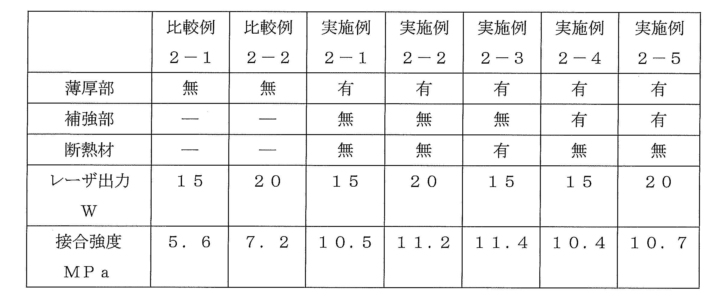
[比較例2-1]
比較例2-1の接合構造体は、金属部材に薄厚部を設けずに、接合工程において、上述した半導体レーザの出力を15Wと設定して、金属部材と樹脂部材とを接合領域で接合させた。
比較例2-1の接合構造体は、金属部材に薄厚部を設けずに、接合工程において、上述した半導体レーザの出力を15Wと設定して、金属部材と樹脂部材とを接合領域で接合させた。
この接合構造体の接合強度は5.6MPaであった。
[比較例2-2]
比較例2-2の接合構造体は、金属部材に薄厚部を設けずに、接合工程において、上述した半導体レーザの出力を20Wと設定して、金属部材と樹脂部材とを接合領域で接合させた。
比較例2-2の接合構造体は、金属部材に薄厚部を設けずに、接合工程において、上述した半導体レーザの出力を20Wと設定して、金属部材と樹脂部材とを接合領域で接合させた。
この接合構造体の接合強度は7.2MPaであった。
[実施例2-1]
実施例2-1の接合構造体100は、金属部材200の裏面の接合領域BF´を取り囲む領域(隣接領域NF´)に、幅0.2mm、深さ2.5mmのスリットを形成して薄厚部とし、接合工程において、上述した半導体レーザの出力を15Wと設定して、金属部材200と樹脂部材300とを接合領域BF´で接合させた。
実施例2-1の接合構造体100は、金属部材200の裏面の接合領域BF´を取り囲む領域(隣接領域NF´)に、幅0.2mm、深さ2.5mmのスリットを形成して薄厚部とし、接合工程において、上述した半導体レーザの出力を15Wと設定して、金属部材200と樹脂部材300とを接合領域BF´で接合させた。
この接合構造体100の接合強度は10.5MPaであった。
[実施例2-2]
実施例2-2の接合構造体100は、金属部材200の裏面の接合領域BF´を取り囲む領域(隣接領域NF´)に、幅0.2mm、深さ2.5mmのスリットを形成して薄厚部とし、接合工程において、上述した半導体レーザの出力を20Wと設定して、金属部材200と樹脂部材300とを接合領域BF´で接合させた。
実施例2-2の接合構造体100は、金属部材200の裏面の接合領域BF´を取り囲む領域(隣接領域NF´)に、幅0.2mm、深さ2.5mmのスリットを形成して薄厚部とし、接合工程において、上述した半導体レーザの出力を20Wと設定して、金属部材200と樹脂部材300とを接合領域BF´で接合させた。
この接合構造体100の接合強度は11.2MPaであった。
[実施例2-3]
実施例2-3の接合構造体100は、金属部材200の裏面の接合領域BF´を取り囲む領域(隣接領域NF´)に、幅0.2mm、深さ2.5mmのスリットを形成して薄厚部とするとともに、各スリット内に断熱材を設け、接合工程において、上述した半導体レーザの出力を15Wと設定して、金属部材200と樹脂部材300とを接合領域BF´で接合させた。
実施例2-3の接合構造体100は、金属部材200の裏面の接合領域BF´を取り囲む領域(隣接領域NF´)に、幅0.2mm、深さ2.5mmのスリットを形成して薄厚部とするとともに、各スリット内に断熱材を設け、接合工程において、上述した半導体レーザの出力を15Wと設定して、金属部材200と樹脂部材300とを接合領域BF´で接合させた。
この接合構造体100の接合強度は11.4MPaであった。
[実施例2-4]
実施例2-4の接合構造体100は、金属部材200の裏面の接合領域BF´を取り囲む領域(隣接領域NF´)に、幅0.2mm、深さ2.5mmのスリットを形成して薄厚部とするとともに、各スリット内の間隙を結ぶように補強部を設け、接合工程において、上述した半導体レーザの出力を15Wと設定して、金属部材200と樹脂部材300とを接合領域BF´で接合させた。
実施例2-4の接合構造体100は、金属部材200の裏面の接合領域BF´を取り囲む領域(隣接領域NF´)に、幅0.2mm、深さ2.5mmのスリットを形成して薄厚部とするとともに、各スリット内の間隙を結ぶように補強部を設け、接合工程において、上述した半導体レーザの出力を15Wと設定して、金属部材200と樹脂部材300とを接合領域BF´で接合させた。
この接合構造体100の接合強度は10.4MPaであった。
[実施例2-5]
実施例2-5の接合構造体100は、金属部材200の裏面の接合領域BF´を取り囲む領域(隣接領域NF´)に、幅0.2mm、深さ2.5mmのスリットを形成して薄厚部とするとともに、各スリット内の間隙を結ぶように補強部を設け、接合工程において、上述した半導体レーザの出力を20Wと設定して、金属部材200と樹脂部材300とを接合領域BF´で接合させた。
実施例2-5の接合構造体100は、金属部材200の裏面の接合領域BF´を取り囲む領域(隣接領域NF´)に、幅0.2mm、深さ2.5mmのスリットを形成して薄厚部とするとともに、各スリット内の間隙を結ぶように補強部を設け、接合工程において、上述した半導体レーザの出力を20Wと設定して、金属部材200と樹脂部材300とを接合領域BF´で接合させた。
この接合構造体100の接合強度は10.7MPaであった。
以上の評価結果から、薄厚部が備えられていない比較例2-1及び2-2の接合構造体の接合強度は、薄厚部23が備えられた実施例2-1~2-5の接合構造体1の接合強度よりも低い結果が得られた。
これにより、本実施形態に対応する接合構造体100によれば、薄厚部が、少なくとも隣接領域NF´を含む領域内に形成されているので、接合領域BF´にレーザを照射して金属部材200と樹脂部材300とを接合させると、接合領域BF´から薄厚部を介して外部に熱拡散することを抑制することができる。これにより、少ないレーザエネルギーで接合領域BF´内にレーザのエネルギーを閉じ込めて、金属部材200と樹脂部材300とを接合させることができる。
なお、上記に示した本発明の実施形態及び実施例はいずれも本発明を具体化した例であって、本発明の技術的範囲を限定する性格のものではない。
1、100 接合構造体
2、200 金属部材
21 凹状部
22 突出部
23 薄厚部
24 補強部
25 断熱材
3、300 樹脂部材
BF、BF´ 接合領域
NF、NF´ 隣接領域
2、200 金属部材
21 凹状部
22 突出部
23 薄厚部
24 補強部
25 断熱材
3、300 樹脂部材
BF、BF´ 接合領域
NF、NF´ 隣接領域
Claims (9)
- 金属部材と樹脂部材とが接合された接合領域を有する接合構造体であって、
前記金属部材の前記接合領域には、当該金属部材の表面に開口を有する凹状部が形成されるとともに、前記金属部材の凹状部には、前記樹脂部材が充填されており、
前記金属部材には、前記接合領域と、該接合領域と隣接する隣接領域と、を包含する領域内に、前記金属部材の厚みが薄くされた薄厚部が設けられていることを特徴とする接合構造体。 - 請求項1に記載された接合構造体であって、
前記薄厚部は、前記接合領域内に形成されていることを特徴とする接合構造体。 - 請求項1に記載された接合構造体であって、
前記薄厚部は、少なくとも前記隣接領域を含む領域内に形成されていることを特徴とする接合構造体。 - 請求項1~3のいずれか1項に記載された接合構造体であって、
前記薄厚部には、断熱材が備えられていることを特徴とする接合構造体。 - 請求項1~4のいずれか1項に記載された接合構造体であって、
前記薄厚部には、前記金属部材を補強する補強部が備えられていることを特徴とする接合構造体。 - 請求項1~5のいずれか1項に記載された接合構造体であって、
前記凹状部の内周面には、内側に突出する突出部が形成されていることを特徴とする接合構造体。 - 金属部材と樹脂部材とが接合された接合領域を有する接合構造体の製造方法であって、
前記金属部材において、前記接合領域と、該接合領域と隣接する隣接領域と、を包含する領域内に、前記金属部材の厚みが薄くされた薄厚部を形成する薄厚部形成工程と、
前記金属部材の表面の前記接合領域に、開口を有する凹状部を形成する凹状部形成工程と、
前記金属部材の表面と前記樹脂部材とを隣接配置する配置工程と、
前記樹脂部材側から前記金属部材の接合領域にレーザを照射することにより、前記金属部材の前記凹状部に前記樹脂部材を充填して接合させる接合工程と、
を備えることを特徴とする接合構造体の製造方法。 - 請求項7に記載された接合構造体の製造方法であって、
前記接合工程では、前記金属部材の接合領域にレーザを照射する際に、前記接合領域内においてレーザを走査させるとともに、前記走査を同一軌跡で複数回行うことを特徴とする接合構造体の製造方法。 - 請求項7又は8に記載された接合構造体の製造方法であって、
前記凹状部形成工程では、1パルスが複数のサブパルスで構成されるレーザを照射することにより、前記凹状部を形成することを特徴とする接合構造体の製造方法。
Applications Claiming Priority (2)
| Application Number | Priority Date | Filing Date | Title |
|---|---|---|---|
| JP2015-008044 | 2015-01-19 | ||
| JP2015008044A JP2016132156A (ja) | 2015-01-19 | 2015-01-19 | 接合構造体及び接合構造体の製造方法 |
Publications (1)
| Publication Number | Publication Date |
|---|---|
| WO2016117502A1 true WO2016117502A1 (ja) | 2016-07-28 |
Family
ID=56417047
Family Applications (1)
| Application Number | Title | Priority Date | Filing Date |
|---|---|---|---|
| PCT/JP2016/051276 Ceased WO2016117502A1 (ja) | 2015-01-19 | 2016-01-18 | 接合構造体及び接合構造体の製造方法 |
Country Status (2)
| Country | Link |
|---|---|
| JP (1) | JP2016132156A (ja) |
| WO (1) | WO2016117502A1 (ja) |
Families Citing this family (2)
| Publication number | Priority date | Publication date | Assignee | Title |
|---|---|---|---|---|
| CN106541209B (zh) * | 2017-01-17 | 2018-02-09 | 镭蒙(苏州)微光学科技有限公司 | 一种用于激光焊接的方法及系统 |
| JP2019113219A (ja) * | 2017-12-21 | 2019-07-11 | 株式会社デンソー | 接合構造体 |
Citations (6)
| Publication number | Priority date | Publication date | Assignee | Title |
|---|---|---|---|---|
| JP2003001455A (ja) * | 2001-06-15 | 2003-01-08 | Matsushita Electric Ind Co Ltd | 金属と樹脂との接合方法及び装置、制振鋼板の製造方法 |
| JP2009226643A (ja) * | 2008-03-19 | 2009-10-08 | Aisin Seiki Co Ltd | 接合方法及び接合体 |
| JP2014018995A (ja) * | 2012-07-13 | 2014-02-03 | Daicel Polymer Ltd | 複合成形体とその製造方法 |
| JP2014091263A (ja) * | 2012-11-05 | 2014-05-19 | Jtekt Corp | 複合成形体 |
| JP2014166693A (ja) * | 2013-02-28 | 2014-09-11 | Daicel Polymer Ltd | 複合成形体とその製造方法 |
| JP2014177051A (ja) * | 2013-03-15 | 2014-09-25 | Denso Corp | 溶着体のレーザー溶着方法 |
Family Cites Families (3)
| Publication number | Priority date | Publication date | Assignee | Title |
|---|---|---|---|---|
| JP2009302209A (ja) * | 2008-06-11 | 2009-12-24 | Nec Electronics Corp | リードフレーム、半導体装置、リードフレームの製造方法および半導体装置の製造方法 |
| JP5690051B2 (ja) * | 2009-05-27 | 2015-03-25 | 公益財団法人名古屋産業科学研究所 | レーザを用いた部材の接合方法 |
| JP2013058739A (ja) * | 2011-08-17 | 2013-03-28 | Dainippon Printing Co Ltd | 光半導体装置用リードフレーム、樹脂付き光半導体装置用リードフレーム、光半導体装置、および、光半導体装置用リードフレームの製造方法 |
-
2015
- 2015-01-19 JP JP2015008044A patent/JP2016132156A/ja active Pending
-
2016
- 2016-01-18 WO PCT/JP2016/051276 patent/WO2016117502A1/ja not_active Ceased
Patent Citations (6)
| Publication number | Priority date | Publication date | Assignee | Title |
|---|---|---|---|---|
| JP2003001455A (ja) * | 2001-06-15 | 2003-01-08 | Matsushita Electric Ind Co Ltd | 金属と樹脂との接合方法及び装置、制振鋼板の製造方法 |
| JP2009226643A (ja) * | 2008-03-19 | 2009-10-08 | Aisin Seiki Co Ltd | 接合方法及び接合体 |
| JP2014018995A (ja) * | 2012-07-13 | 2014-02-03 | Daicel Polymer Ltd | 複合成形体とその製造方法 |
| JP2014091263A (ja) * | 2012-11-05 | 2014-05-19 | Jtekt Corp | 複合成形体 |
| JP2014166693A (ja) * | 2013-02-28 | 2014-09-11 | Daicel Polymer Ltd | 複合成形体とその製造方法 |
| JP2014177051A (ja) * | 2013-03-15 | 2014-09-25 | Denso Corp | 溶着体のレーザー溶着方法 |
Also Published As
| Publication number | Publication date |
|---|---|
| JP2016132156A (ja) | 2016-07-25 |
Similar Documents
| Publication | Publication Date | Title |
|---|---|---|
| JP6414477B2 (ja) | 接合構造体の製造方法 | |
| JP6451370B2 (ja) | 接合構造体の製造方法 | |
| WO2016027775A1 (ja) | 接合構造体および接合構造体の製造方法 | |
| CN107921713B (zh) | 接合结构体的制造方法及接合结构体 | |
| KR101893073B1 (ko) | 접합 구조체의 제조방법 및 접합 구조체 | |
| JP6417786B2 (ja) | 接合構造体の製造方法 | |
| JP6439455B2 (ja) | 接合構造体の製造方法 | |
| JP6398778B2 (ja) | 接合構造体の製造方法および接合構造体 | |
| WO2016125594A1 (ja) | 接合構造体の製造方法および接合構造体 | |
| JP6432364B2 (ja) | 接合構造体の製造方法 | |
| WO2016140097A1 (ja) | 接合方法、接合構造体の製造方法および接合構造体 | |
| WO2016117502A1 (ja) | 接合構造体及び接合構造体の製造方法 | |
| JP6424665B2 (ja) | 接合構造体の製造方法 | |
| WO2016143585A1 (ja) | 加工方法、接合構造体の製造方法および接合構造体 | |
| WO2016117501A1 (ja) | レーザ溶着方法および接合構造体 | |
| KR101917768B1 (ko) | 이종접합 성형체 | |
| WO2022185739A1 (ja) | 接合体の製造方法、および接合体 |
Legal Events
| Date | Code | Title | Description |
|---|---|---|---|
| 121 | Ep: the epo has been informed by wipo that ep was designated in this application |
Ref document number: 16740109 Country of ref document: EP Kind code of ref document: A1 |
|
| NENP | Non-entry into the national phase |
Ref country code: DE |
|
| 122 | Ep: pct application non-entry in european phase |
Ref document number: 16740109 Country of ref document: EP Kind code of ref document: A1 |