WO2016114199A1 - 局側装置及び波長制御方法 - Google Patents
局側装置及び波長制御方法 Download PDFInfo
- Publication number
- WO2016114199A1 WO2016114199A1 PCT/JP2016/050256 JP2016050256W WO2016114199A1 WO 2016114199 A1 WO2016114199 A1 WO 2016114199A1 JP 2016050256 W JP2016050256 W JP 2016050256W WO 2016114199 A1 WO2016114199 A1 WO 2016114199A1
- Authority
- WO
- WIPO (PCT)
- Prior art keywords
- wavelength
- signal
- chromatic dispersion
- delay amount
- subscriber
- Prior art date
- Legal status (The legal status is an assumption and is not a legal conclusion. Google has not performed a legal analysis and makes no representation as to the accuracy of the status listed.)
- Ceased
Links
Images






Classifications
-
- H—ELECTRICITY
- H04—ELECTRIC COMMUNICATION TECHNIQUE
- H04J—MULTIPLEX COMMUNICATION
- H04J14/00—Optical multiplex systems
- H04J14/02—Wavelength-division multiplex systems
- H04J14/0227—Operation, administration, maintenance or provisioning [OAMP] of WDM networks, e.g. media access, routing or wavelength allocation
- H04J14/0241—Wavelength allocation for communications one-to-one, e.g. unicasting wavelengths
- H04J14/0242—Wavelength allocation for communications one-to-one, e.g. unicasting wavelengths in WDM-PON
- H04J14/0245—Wavelength allocation for communications one-to-one, e.g. unicasting wavelengths in WDM-PON for downstream transmission, e.g. optical line terminal [OLT] to ONU
- H04J14/0246—Wavelength allocation for communications one-to-one, e.g. unicasting wavelengths in WDM-PON for downstream transmission, e.g. optical line terminal [OLT] to ONU using one wavelength per ONU
-
- H—ELECTRICITY
- H04—ELECTRIC COMMUNICATION TECHNIQUE
- H04B—TRANSMISSION
- H04B10/00—Transmission systems employing electromagnetic waves other than radio-waves, e.g. infrared, visible or ultraviolet light, or employing corpuscular radiation, e.g. quantum communication
- H04B10/07—Arrangements for monitoring or testing transmission systems; Arrangements for fault measurement of transmission systems
- H04B10/075—Arrangements for monitoring or testing transmission systems; Arrangements for fault measurement of transmission systems using an in-service signal
- H04B10/079—Arrangements for monitoring or testing transmission systems; Arrangements for fault measurement of transmission systems using an in-service signal using measurements of the data signal
- H04B10/0793—Network aspects, e.g. central monitoring of transmission parameters
-
- H—ELECTRICITY
- H04—ELECTRIC COMMUNICATION TECHNIQUE
- H04B—TRANSMISSION
- H04B10/00—Transmission systems employing electromagnetic waves other than radio-waves, e.g. infrared, visible or ultraviolet light, or employing corpuscular radiation, e.g. quantum communication
- H04B10/25—Arrangements specific to fibre transmission
- H04B10/2507—Arrangements specific to fibre transmission for the reduction or elimination of distortion or dispersion
- H04B10/2513—Arrangements specific to fibre transmission for the reduction or elimination of distortion or dispersion due to chromatic dispersion
-
- H—ELECTRICITY
- H04—ELECTRIC COMMUNICATION TECHNIQUE
- H04J—MULTIPLEX COMMUNICATION
- H04J14/00—Optical multiplex systems
- H04J14/02—Wavelength-division multiplex systems
- H04J14/0226—Fixed carrier allocation, e.g. according to service
-
- H—ELECTRICITY
- H04—ELECTRIC COMMUNICATION TECHNIQUE
- H04J—MULTIPLEX COMMUNICATION
- H04J14/00—Optical multiplex systems
- H04J14/02—Wavelength-division multiplex systems
- H04J14/0227—Operation, administration, maintenance or provisioning [OAMP] of WDM networks, e.g. media access, routing or wavelength allocation
- H04J14/0241—Wavelength allocation for communications one-to-one, e.g. unicasting wavelengths
- H04J14/0242—Wavelength allocation for communications one-to-one, e.g. unicasting wavelengths in WDM-PON
- H04J14/0249—Wavelength allocation for communications one-to-one, e.g. unicasting wavelengths in WDM-PON for upstream transmission, e.g. ONU-to-OLT or ONU-to-ONU
- H04J14/025—Wavelength allocation for communications one-to-one, e.g. unicasting wavelengths in WDM-PON for upstream transmission, e.g. ONU-to-OLT or ONU-to-ONU using one wavelength per ONU, e.g. for transmissions from-ONU-to-OLT or from-ONU-to-ONU
-
- H—ELECTRICITY
- H04—ELECTRIC COMMUNICATION TECHNIQUE
- H04J—MULTIPLEX COMMUNICATION
- H04J14/00—Optical multiplex systems
- H04J14/02—Wavelength-division multiplex systems
- H04J14/0227—Operation, administration, maintenance or provisioning [OAMP] of WDM networks, e.g. media access, routing or wavelength allocation
- H04J14/0254—Optical medium access
- H04J14/0256—Optical medium access at the optical channel layer
-
- H—ELECTRICITY
- H04—ELECTRIC COMMUNICATION TECHNIQUE
- H04J—MULTIPLEX COMMUNICATION
- H04J14/00—Optical multiplex systems
- H04J14/02—Wavelength-division multiplex systems
- H04J14/0278—WDM optical network architectures
-
- H—ELECTRICITY
- H04—ELECTRIC COMMUNICATION TECHNIQUE
- H04J—MULTIPLEX COMMUNICATION
- H04J14/00—Optical multiplex systems
- H04J14/02—Wavelength-division multiplex systems
- H04J14/0278—WDM optical network architectures
- H04J14/0282—WDM tree architectures
-
- H—ELECTRICITY
- H04—ELECTRIC COMMUNICATION TECHNIQUE
- H04J—MULTIPLEX COMMUNICATION
- H04J14/00—Optical multiplex systems
- H04J14/08—Time-division multiplex systems
-
- H—ELECTRICITY
- H04—ELECTRIC COMMUNICATION TECHNIQUE
- H04J—MULTIPLEX COMMUNICATION
- H04J3/00—Time-division multiplex systems
-
- H—ELECTRICITY
- H04—ELECTRIC COMMUNICATION TECHNIQUE
- H04L—TRANSMISSION OF DIGITAL INFORMATION, e.g. TELEGRAPHIC COMMUNICATION
- H04L12/00—Data switching networks
- H04L12/28—Data switching networks characterised by path configuration, e.g. LAN [Local Area Networks] or WAN [Wide Area Networks]
- H04L12/44—Star or tree networks
-
- H—ELECTRICITY
- H04—ELECTRIC COMMUNICATION TECHNIQUE
- H04J—MULTIPLEX COMMUNICATION
- H04J14/00—Optical multiplex systems
- H04J14/02—Wavelength-division multiplex systems
- H04J14/0227—Operation, administration, maintenance or provisioning [OAMP] of WDM networks, e.g. media access, routing or wavelength allocation
- H04J14/0241—Wavelength allocation for communications one-to-one, e.g. unicasting wavelengths
- H04J14/0242—Wavelength allocation for communications one-to-one, e.g. unicasting wavelengths in WDM-PON
- H04J2014/0253—Allocation of downstream wavelengths for upstream transmission
Definitions
- the present invention relates to a station side device and a wavelength control method.
- the Passive Optical Network (PON) system has been introduced all over the world as an optical communication system supporting the Fiber To The Home (FTTH) service, which has been rapidly spreading.
- a single station side device (OLT: Optical Line Terminal) installed in a receiving station is installed in a plurality of subscriber homes via an optical splitter installed in an optical fiber transmission line.
- OLT Optical Line Terminal
- ONU Optical Network Unit
- NG-PON2 In addition to speeding up from the conventional PON system, in addition to the time multiplexing (TDM: Time Division Multiplexing) that has been used in PON systems so far, the optical communication network has been improved.
- TDM Time Division Multiplexing
- a WDM / TDM-PON system that can improve the efficiency of accommodation and maintenance management by using wavelength division multiplexing (WDM: Wavelength Division Multiplexing) that takes advantage of the above characteristics has been studied. ing.
- the wavelength allocation of WDM / TDM-PON currently under consideration for standardization is expected to coexist with GE-PON, 10G-EPON, video services, maintenance management function wavelength bands, etc., and is used in existing optical communication systems.
- the use of 1524 to 1544 nm in the non-C band and 1596 to 1603 nm in the L band is under consideration.
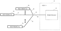
- FIG. 1 and 2 show a typical configuration of a wavelength tunable WDM / TDM-PON using a splitter network.
- FIG. 1 and FIG. 2 show cases where the positions of the accommodated ONUs 20 are all the same or different with reference to the OLT 10.
- the wavelength variable ONU 20 and the OLT 10 are connected via optical fiber transmission lines 40, 41, 42, 50 and an optical splitter 30.
- the OLT 10 is disposed in the housing building 11. Also, a form using an optical multiplexer / demultiplexer (AWG) instead of the splitter 30 is also conceivable.
- ATG optical multiplexer / demultiplexer
- the ONU 20 is equipped with a wavelength variable burst transceiver.
- the wavelength tunable burst transmitter / receiver can perform a wavelength tunable burst transmission / reception operation in which a burst signal is transmitted / received in a variable wavelength manner.
- the OLT 10 uses the bandwidth in the TDM region and the wavelength in the WDM region effectively by using the DWBA (Dynamic Wavelength and Bandwidth Allocation) function implemented in the MAC (Media Access Control) control unit of the OLT 10, thereby providing fair bandwidth between users. Realization of advanced optical communication networks such as control, OLT protection, and power-saving operation.
- DWBA Dynamic Wavelength and Bandwidth Allocation
- WDM / TDM-PON system wavelengths can coexist with existing GE-PON and G-PON, video wavelength bands, and standardized 10GE-PON and XG-PON.
- the unused wavelength band C band 1524 to 1544 nm is assigned to the upstream signal and the L band 1596 to 1603 nm is assigned to the downstream signal.
- 3 and 4 show an example of wavelength allocation in the wavelength tunable WDM / TDM-PON system related to the present invention.
- the WDM / TDM-PON system there is a wavelength pair assignment method for assigning a wavelength pair that is a pair of wavelengths for round-trip communication between the OLT 10 and the ONU 20 by an upstream signal from the OLT 10 to the ONU 20 and a downstream signal from the ONU 20 to the OLT 10.
- the round trip communication refers to round-trip transfer communication in which the OLT 10 transmits a downstream signal and the ONU 20 transmits an upstream signal toward the OLT 10.
- an upstream signal and a downstream signal are sequentially paired from the short wavelength side to form a wavelength pair, and the wavelength pair is assigned to each ONU 20.
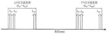
- the uplink signal and the downlink signal are set to ⁇ u1 to ⁇ um and ⁇ d1 to ⁇ dm from the short wavelength side, respectively, as shown in FIG.
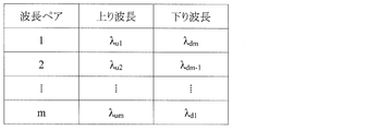
- Signals are grouped one by one in order from the short wavelength side to form a wavelength pair, and any wavelength pair is assigned to the ONU 20.
- the wavelength pair 1 is a combination of ⁇ u1 and ⁇ d1
- the OLT 10 transmits a signal to the ONU 20 using the wavelength ⁇ d1
- the ONU 20 transmits a signal to the OLT 10 using the wavelength ⁇ u1 .
- the upstream and downstream wavelengths of the WDM / TMD-PON system use the 1.5 ⁇ m band, and the upstream and downstream signals have wavelength bandwidths of 20 nm and 7 nm, respectively.
- the amount of chromatic dispersion delay received by the chromatic dispersion of the signal may affect the system.
- the chromatic dispersion delay amount D by the round trip communication can be calculated by the equation (1).
- the transmission distance is L
- the upstream signal wavelength bandwidth is B u
- the upstream signal wavelength dispersion amount is D u
- the downstream signal wavelength bandwidth is B d
- the downstream signal wavelength dispersion amount is D d .
- the upstream signal wavelength bandwidth B u is an absolute value of the difference between the wavelength of the reference signal in the upstream signal and the wavelength of the target signal.
- the upstream signal chromatic dispersion amount D u is a coefficient of the change amount of the chromatic dispersion amount estimated from the wavelength of the reference signal and the wavelength range of the target signal.
- the downlink signal wavelength bandwidth Bd is an absolute value of the difference between the wavelength of the reference signal in the downlink signal and the wavelength of the target signal.
- the downlink signal chromatic dispersion amount D d is a coefficient of the change amount of the chromatic dispersion amount estimated from the wavelength of the reference signal and the wavelength range of the target signal.
- the chromatic dispersion delay amount D due to the round trip is the dispersion delay amount at the wavelength pair of the reference signal in the case of performing transmission by round trip using a pair of upstream and downstream signals of a plurality of wavelengths between the OLT 10 and the ONU 20. This is the difference in dispersion delay amount in the wavelength pair of the target signal.
- the chromatic dispersion delay amount D due to the round trip is the delay when the round trip transmission is performed using the reference signal wavelength pair and the round trip transmission is performed using the target signal wavelength pair. Equal to the difference in delay.
- the wavelength pair 1 is a combination of the wavelength of the reference signal in the upstream signal and the wavelength of the reference signal in the downstream signal.
- Formula (2) shows the calculation result of the maximum value of the chromatic dispersion delay amount D due to the round trip when the optical communication system uses the wavelength pairs shown in FIGS.
- the reference signal is the signal of the wavelength pair 1 in FIG. 4, and the chromatic dispersion delay amount D due to the round trip occurring in the wavelength pair m in FIG.
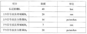
- each specification discussed in the general NG-PON 2 as shown in FIG. 5 is used. Specifically, L is 40 km, B u is 20 nm, D u is 16 ps / nm / km, B d is 7 nm, and D d is 20 ps / nm / km.
- the maximum value of the chromatic dispersion delay amount D due to the 40 km round trip is 18.4 ns.
- the maximum value of the chromatic dispersion delay amount D due to the round trip becomes a larger value when the transmission distance is 40 km or more because the L value affects the previous term.
- the recommended value of laser Ton and Toff time in G-PON and XG-PON standardized by ITU-T is 32 bits (12.8 nsec) or less, and the synchronization function that has been increasingly demanded in recent years Considering these factors, the system requirements for delays are expected to become even stricter in the future.
- the present invention provides a station-side device that reduces a difference in delay amount generated between an upstream signal and a downstream signal when round-trip communication is performed in an optical communication system using WDM / TDM-PON.
- the purpose is to provide.
- the station-side apparatus of the present invention determines the combination of wavelength pairs used for uplink and downlink signals from each wavelength pair.
- the maximum value of the calculated chromatic dispersion delay amount is configured to be smaller than the maximum value of the chromatic dispersion delay amount calculated when the combination of wavelength pairs used for the upstream and downstream signals are both assigned from the shortwave side.
- the station-side device of the present invention includes a station-side device and a plurality of subscriber-side devices that are connected via an optical transmission line, the wavelength-division multiplexing, and the station-side device to the subscriber-side device.
- the value is smaller than the maximum value of the chromatic dispersion delay amount calculated when the wavelength of the upstream signal and the wavelength of the downstream signal are assigned in order from the short wavelength side.
- the wavelength pairs for each of the subscriber-side devices are assigned the wavelength of the upstream signal in order from the short wavelength side and the wavelength of the downstream signal in order from the long wavelength side, Alternatively, the wavelength of the upstream signal may be assigned in order from the long wavelength side, and the wavelength of the downstream signal may be assigned in order from the short wavelength side.
- the uplink is a chromatic dispersion delay amount of the wavelength pair assigned to any one of the plurality of subscriber side apparatuses and is estimated in the optical transmission line If the chromatic dispersion delay amount calculated using the chromatic dispersion amount generated in the signal wavelength and the downstream signal wavelength exceeds a predetermined threshold, the wavelength pair assigned to the subscriber side device is changed. May be.
- the uplink is a chromatic dispersion delay amount of the wavelength pair assigned to any one of the plurality of subscriber side apparatuses and is estimated in the optical transmission line
- the chromatic dispersion delay amount calculated using the chromatic dispersion amount generated in the signal wavelength and the downstream signal wavelength exceeds a predetermined threshold, the wavelength pairs assigned to the plurality of subscriber-side devices All of these may be changed.
- the uplink is a chromatic dispersion delay amount of the wavelength pair assigned to two or more subscriber-side apparatuses among the plurality of subscriber-side apparatuses, and is estimated in the optical transmission line
- the chromatic dispersion delay amount exceeds the threshold.
- a certain wavelength pair may be assigned to another subscriber-side device whose chromatic dispersion delay amount exceeds a threshold value.
- a station-side device and a plurality of subscriber-side devices connected via an optical transmission line use wavelength division multiplexing from the station-side device to the subscriber-side device.
- the wavelength pair is a chromatic dispersion delay amount calculated when the maximum value of the chromatic dispersion delay amount calculated from each wavelength pair assigns the wavelength of the upstream signal and the wavelength of the downstream signal in order from the short wavelength side. Less than the maximum value.
- the wavelength control method of the present invention when the distance between the station side device and the subscriber side device exceeds the predetermined threshold, the wavelength pair assigned to the subscriber side device is changed. May be.
- an optical communication system using WDM / TDM-PON provides a station-side device that reduces a difference in delay amount generated between an upstream signal and a downstream signal when round-trip communication is performed. Can do.
- 1 shows a first example of a wavelength division multiplexing optical communication system related to the present invention.
- 2 shows a second example of a wavelength division multiplexing optical communication system related to the present invention.
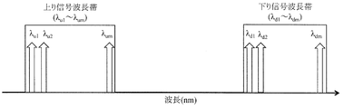
- 2 shows an example of the wavelength of an upstream signal and the wavelength of a downstream signal in a wavelength division multiplexing optical communication system related to the present invention.
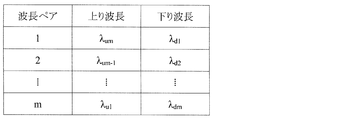
- An example of the wavelength pair of the wavelength of the upstream signal and the wavelength of the downstream signal in the wavelength division multiplexing optical communication system related to the present invention is shown.
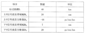
- An example of the conditions at the time of calculating the amount of chromatic dispersion delay due to a round trip in the wavelength division multiplexing optical communication system related to the present invention will be shown.
- FIG. 2 shows examples of upstream signal wavelengths and downstream signal wavelengths in the wavelength division multiplexing optical communication system according to the first embodiment of the present invention.
- 3 shows an example of a wavelength pair of an upstream signal wavelength and a downstream signal wavelength in the wavelength division multiplexing optical communication system according to the first embodiment of the present invention.
- An example of the conditions at the time of calculating the chromatic dispersion delay amount by the round trip which concerns on Embodiment 1 of this invention is shown.
- 4 shows an example of an upstream signal wavelength and a downstream signal wavelength in a wavelength division multiplexing optical communication system according to a second embodiment of the present invention.
- 7 shows an example of a wavelength pair of an upstream signal wavelength and a downstream signal wavelength in the wavelength division multiplexing optical communication system according to the second embodiment of the present invention.
- An example of the conditions at the time of calculating the chromatic dispersion delay amount by the round trip which concerns on Embodiment 2 of this invention is shown.
- An example of the wavelength pair change flow in the wavelength division multiplexing optical communication system concerning Embodiment 3 of the present invention is shown.
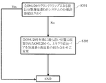
- An example of the wavelength pair change flow in the wavelength division multiplexing optical communication system which concerns on Embodiment 4 of this invention is shown.
- An example of the wavelength pair change flow in the wavelength division multiplexing optical communication system concerning Embodiment 5 of this invention is shown.
- An example of the distance dependence of the dispersion delay amount by the wavelength pairing combination according to the present embodiment is shown.
- the optical communication system includes an OLT 10, an ONU 20, and an optical transmission line.
- the optical transmission line includes optical fiber transmission lines 40, 41, 42, 50 and an optical splitter 30.
- the optical splitter 30 may function as a WM (Weighting Mux) that multiplexes and demultiplexes light.
- the OLT 10 assigns a wavelength pair for round trip communication to each ONU 20. At this time, the OLT 10 assigns the wavelengths of the uplink signal and the downlink signal so as to reduce the chromatic dispersion delay amount D due to the round trip in the communication between the OLT 10 and the ONU 20. The OLT 10 and each ONU 20 perform round trip communication according to the assignment of the wavelength pair.
- the OLT 10 transmits a downlink signal to each ONU 20 according to the assignment of the wavelength pair.
- Each ONU 20 sets the transmission / reception wavelength of the tunable burst transmitter / receiver according to the wavelength pair assignment, receives the downlink signal from the OLT 10, and transmits the uplink signal to the OLT 10.
- the OLT 10 receives the upstream signal from each ONU 20 according to the wavelength pair assignment.
- the components of each port in the OLT 10 and the OSU Optical Transmit / Receive Unit: Optical Subscriber Unit
- CT Channel Termination
- FIG. 6 and 7 show an example of the wavelength pair according to the present embodiment.
- WDM / TDM-PON when an optical communication system using WDM / TDM-PON performs round-trip communication, due to the influence of chromatic dispersion in the upstream and downstream signal wavelength bands described using FIG. 5 and Equation (2), The amount of dispersion delay generated in the wavelength pair is reduced.
- WDM / TDM-PON according to the present embodiment is used synonymously with TWDM (Time and Wavelength division multiplexing) -PON.
- the uplink / downlink signal is assumed to have an arbitrary number of wavelengths m, but this method is effective when the number of uplink and downlink wavelengths is different.
- the upstream and downstream signals are composed of m signals arranged at equal wavelength intervals as in FIG. 3, and numbers are assigned from the short wavelength side as shown in FIG. I will do it.
- both the upstream and downstream signals are combined as a wavelength pair so that the wavelength becomes longer in order from the reference signal.
- the upstream signal is combined as a wavelength pair and the downstream signal is combined as a wavelength pair from the long wavelength side.
- each wavelength pair is configured as shown in the table of FIG.
- the reference signal is the signal of the wavelength pair 1 in FIG. 7, and the chromatic dispersion delay amount D due to the round trip occurring in the wavelength pair m in FIG. Moreover, in the calculation of Formula (3), the value shown in FIG. 8 was used.
- the chromatic dispersion delay amount D due to round trip in the case of using the wavelength pair according to the optical communication system related to the present invention calculated using the conditions shown in FIG. 5 is 18.4 ns. Therefore, in the present embodiment, it is possible to reduce the chromatic dispersion delay amount D due to the round trip by 11.2 ns as compared with the case where the conditions shown in FIG. 5 are used.
- the NG-PON2 upstream / downstream signal wavelength discussed in FSAN / ITU-T has been discussed as an example.
- the present embodiment covers all optical communication wavelength bands and all frequencies of upstream / downstream signals. Valid at intervals. It is also effective in extending the distance over 40 km. According to the present embodiment, it is possible to reduce the chromatic dispersion delay amount D due to round trip when the optical communication system performs round trip communication only by changing the combination of wavelength pairs.
- the wavelength multiplexing optical communication system shown in FIG. 2 all the ONUs 20 are accommodated at different positions. However, in this embodiment, only some of the ONUs 20 may be accommodated in different positions, or the ONUs 20 may be accommodated in two or more positions, and an arbitrary number of ONUs 20 may be accommodated in the respective positions. .
- the wavelength pair 1 is a combination of the wavelength of the reference signal in the upstream signal and the wavelength of the reference signal in the downstream signal, but another wavelength pair may be a combination of the wavelengths of the reference signal.
- each wavelength pair is affected by the influence of chromatic dispersion in the upstream and downstream signal wavelength bands described with reference to FIG. 5 and Equation (2). Reduce the amount of dispersion delay that occurs.
- the upstream / downstream signal is composed of an arbitrary number m of wavelengths, but this embodiment is effective even when the number of upstream and downstream wavelengths is different. Further, the present embodiment is effective even when the wavelength intervals of the upstream and downstream signals are the same as well as different.
- the upstream and downstream signals are composed of m signals arranged at equal wavelength intervals as in FIG. 3, and numbers are assigned from the short wavelength side as shown in the figure.
- the upstream signal and the downstream signal are combined as a wavelength pair so that the wavelength becomes longer in order from the wavelength of the reference signal.
- the upstream signal is combined from the long wavelength side
- the downstream signal is combined from the short wavelength side as a wavelength pair, respectively.
- the upstream signal wavelength dispersion amount D u when considering the maximum value of the chromatic dispersion amount of delay D in a round trip of the present embodiment, the upstream signal wavelength dispersion amount D u to allocate from the long wavelength side in the wavelength pair, criteria for the long wavelength side Since the wavelength ⁇ um assigned to the wavelength pair 1 shown in FIG. 10 as a reference is defined as a reference, the chromatic dispersion amount for ⁇ u1 assigned to the wavelength pair m that is a signal located on the short wavelength side of 20 nm is defined. , Will take a negative value.
- the chromatic dispersion delay amount D due to the round trip calculated by the equation (4) is ⁇ 7.2 ns, and the wavelength pair related to the optical communication system related to the present invention shown in FIG. Compared to the dispersion delay amount of 18.4 ns when used, it is possible to reduce 25.6 ns.
- the NG-PON2 upstream / downstream signal wavelength discussed in FSAN / ITU-T has been discussed as an example.
- all optical communication wavelength bands and all frequencies of upstream / downstream signals are discussed. Valid at intervals. It is also effective in extending the distance over 40 km. According to the present embodiment, it is possible to reduce the chromatic dispersion delay amount D due to round trip when the WDM / TDM-PON system performs round trip communication only by changing the combination of wavelengths used for the wavelength pair.
- FIG. 12 shows a flowchart regarding wavelength pair change in a WDM / TDM-PON in which all ONUs 20 are accommodated at the same distance as shown in FIG.
- the OLT 10 changes the wavelength pairs assigned to all the ONUs 20 when a chromatic dispersion delay amount D due to a round trip that exceeds a threshold defined as a system dispersion allowable value is found.
- a threshold defined as a system dispersion allowable value
- the wavelengths, chromatic dispersion amounts D u and D d , and wavelength bandwidths B u and B d used in the upstream signal and downstream signal can be grasped in advance. Therefore, if the accommodation positions of all the ONUs 20, that is, the transmission distance L can be grasped, the dispersion delay amount D due to the round trip of the entire optical communication system can be uniquely obtained using the equations (1) to (4).
- An access system represented by the PON system has a ranging function in order to grasp the accommodation position of the ONU 20. For this reason, in this embodiment, based on the accommodation position information of all ONUs 20 specified by the ranging function, chromatic dispersion delay amounts D due to round trips between the OLT 10 and the respective ONUs 20 are derived and set in advance.
- the wavelength pair change determination is performed by comparing the dispersion tolerance of the system (for example, 12.8 nsec, which is the Ton / Toff time defined by G-PON).
- step S101 if the chromatic dispersion delay amount D due to round trip calculated using the transmission distance L of each ONU 20 derived by ranging is within the dispersion tolerance of the system, the wavelength pair No changes are made.
- the chromatic dispersion delay amount D due to the round trip in at least one ONU 20 exceeds the allowable dispersion value of the system (for example, 12.8 nsec, which is the Ton / Toff time defined by G-PON). If so, the process proceeds to step S102.
- the wavelength pair is changed as in the first or second embodiment. According to the present embodiment, it is possible to reduce the chromatic dispersion delay amount D due to the round trip when the WDM / TDM-PON performs the round trip communication only by changing the combination of the wavelength pairs.
- an optical signal is configured by overlapping a plurality of light waves (light waves).
- the propagation constant of each light wave differs depending on the frequency of the light wave.
- a physical phenomenon in which the propagation constant changes with frequency is called dispersion.
- dispersion factors In general single mode optical fibers, there are mainly two types of dispersion factors called 1) material dispersion and 2) waveguide dispersion. These dispersions affect the optical pulse spread during optical signal transmission, and limit transmission distance and transmission speed.
- the material dispersion amount D m resulting from the material dispersion is given by the following equation.
- d ⁇ is the spread of the pulse
- ⁇ is the optical signal wavelength
- c is the frequency of the optical signal.
- the unit of Dm is expressed in ps / km / nm, and means the spectrum spread when an optical signal having a spectral width of 1 nm is transmitted for 1 km.
- waveguide dispersion is dispersion that affects the propagation constant depending on the frequency due to the difference in refractive index between the core portion and the cladding portion of the optical fiber.
- Waveguide dispersion amount D w due to waveguide dispersion is given by the following equation. ⁇ is the normalized frequency, and ⁇ is the refractive index ratio between the core and the cladding.
- the dispersion amount D of a general single mode fiber becomes zero when the optical signal wavelength ⁇ is around 1300 nm. In the vicinity of 1550 nm, which is the low-loss wavelength band of the optical fiber, the optical signal is transmitted by 1 km, and a dispersion amount D of about 17 ps / km / nm is given to the optical signal. This means that an optical pulse spreads by 17 ps when an optical signal is transmitted by 1 km.
- FIG. 15 shows the distance dependence characteristics of the dispersion delay amount due to the combination of wavelength pairing at the wavelength pair switching threshold.
- L1 represents the first embodiment
- L2 represents the second embodiment
- L3 represents the case of using the wavelength pair shown in FIG.
- the upstream wavelength becomes longer wavelength sequentially from the reference signal
- the downstream wavelength becomes shorter wavelength sequentially from the reference signal.
- the upstream wavelength is shorter from the reference signal and the downstream wavelength is longer from the reference signal.
- the dispersion amount D in the uplink signal and the dispersion amount D in the downlink signal cancel each other out in the uplink signal and the downlink signal from Equations (5) and (6).
- L1 and L2 have a smaller amount of dispersion delay than L3.
- the dispersion delay amount between the shortest wavelength pair and the longest wavelength pair at the time of 40 km transmission is 18. 2 ns.
- These dispersion delay amounts increase in proportion to the distance, and when taking into account further widening, which is a trend of recent access systems, for example, a dispersion delay amount of 46 ns occurs at the time of 100 km transmission.
- the Ton time assigned to the laser rising of the ONU transmitter is 12.8 ns. Therefore, in the wavelength pair configuration according to the related art, a dispersion delay amount exceeding these Ton occurs at the time of 40 km transmission. For example, at the time of wavelength switching, the communication delay time occurs due to these dispersion delay amounts, and the band is consumed.
- the dispersion delay amount during 40 km transmission is suppressed to 7.2 ns.
- the change from the wavelength pair according to the related technology to the wavelength pair according to the present embodiment is performed by checking the ONU accommodation distance information by the OLT ranging and the distance dependency characteristic of the dispersion delay amount in the OLT, and setting the wavelength pairing change threshold value. If it exceeds, change it.
- the wavelength pairing change threshold is set to 12.8 ns, which is the Ton specification of the laser mounted on the ONU.
- FIG. 13 shows a flowchart regarding wavelength pair change according to chromatic dispersion delay amount D due to round trip in WDM / TDM-PON in which all ONUs 20 are accommodated at different positions as shown in FIG. Also in this embodiment, as a premise, it is assumed that the initial set wavelength pair of the uplink / downlink signal of WDM / TDM-PON is combined from the short wavelength side shown in FIG.
- the present embodiment uses the ranging function in the PON system. For this reason, in this embodiment, based on the accommodation position information of the ONUs 20 specified by these ranging functions, chromatic dispersion delay amounts D due to round trips in the respective ONUs 20 are derived, and these and the dispersion dispersion values set in advance by the system Are compared to determine whether to change the wavelength pair.
- step S201 when the chromatic dispersion delay amount D due to the round trip of all ONUs 20 guided by the ranging is within the dispersion allowable value of the system, the wavelength pair is not changed.
- step S201 if any one of the ONUs 20 having different accommodation positions has a chromatic dispersion delay amount D due to a round trip that exceeds the system dispersion allowable value, the wavelength pairs of all the ONUs 20 are determined in step S202. It changes like Embodiment 1 or Embodiment 2. According to the present embodiment, it is possible to reduce the chromatic dispersion delay amount D due to the round trip when the WDM / TDM-PON performs the round trip communication only by changing the combination of the wavelength pairs.
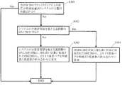
- FIG. 14 shows a flowchart regarding the wavelength pair change according to the chromatic dispersion delay amount D due to the round trip in the WDM / TDM-PON in which all the ONUs 20 are accommodated at different positions as shown in FIG. Also in this embodiment, as a premise, it is assumed that the initial set wavelength pair of the uplink / downlink signal of WDM / TDM-PON is combined from the short wavelength side shown in FIG.
- the chromatic dispersion delay amount D due to the round trip in all the ONUs 20 is uniquely obtained. Similar to the third and fourth embodiments, this method also utilizes the ranging function in the PON system. For this reason, in this embodiment, based on the accommodation position information of the ONUs 20 specified by these ranging functions, the chromatic dispersion delay amount D due to round trips in all the ONUs 20 is derived, and these and the dispersion tolerance values set in advance for the system are obtained. By comparing, the wavelength pair change determination is performed.
- step S301 when the chromatic dispersion delay amount D due to the round trip of all ONUs 20 derived by ranging is within the dispersion allowable value of the system, the wavelength pair is not changed.
- step S301 if the chromatic dispersion delay amount D due to the round trip of at least one ONU 20 among the ONUs 20 having different accommodation positions exceeds the system allowable dispersion value, the process proceeds to step S302.
- step S302 when there are two or more ONUs 20 in which the chromatic dispersion delay amount D due to the round trip does not satisfy the system dispersion allowable value, the process proceeds to step S303.
- step S303 among the wavelengths used in the ONU 20 in which the chromatic dispersion delay amount D due to round trip exceeds the allowable dispersion value of the system, the wavelength pair is changed as in the first or second embodiment.
- the process proceeds to step S304, and the wavelength pairs of all ONUs 20 are the same as in the fourth embodiment. Are changed as in the first or second embodiment.
- the OLT 10 is connected to an external control device (not shown) and may use a wavelength pair calculated by an engineer via the control device, or the control device may calculate the wavelength pair in advance. May be input to the OLT 10.
- the wavelength pairs used by all the ONUs 20 are changed so that the chromatic dispersion delay amount D due to the round trip is within the allowable dispersion value of the system.
- the flow of the third to fifth embodiments may be repeated so that the chromatic dispersion delay amount D due to the round trip is within the allowable dispersion value of the system, or the flows of the third to fifth embodiments are combined. May be used.
- the wavelength pair used by at least one ONU 20 is the sum of the chromatic dispersion delay amounts D due to the round trips of all ONUs 20 regardless of whether the chromatic dispersion delay amount D due to the round trip exceeds the allowable dispersion value of the system.
- the average may be changed to be a minimum or constant value, or the chromatic dispersion delay amount D due to the round trip of all ONUs 20 may be changed to be in a constant range.
- the station apparatus of the present invention can be applied to the communication industry.
- OLT 11 Containment building 20: ONU 30: Optical splitters 40, 41, 42, 50: Optical fiber transmission line
Landscapes
- Engineering & Computer Science (AREA)
- Computer Networks & Wireless Communication (AREA)
- Signal Processing (AREA)
- Physics & Mathematics (AREA)
- Electromagnetism (AREA)
- Optical Communication System (AREA)
- Small-Scale Networks (AREA)
Abstract
本発明のWDM/TDM-PONを用いた光通信システムにおいて、ラウンドトリップ通信した際に上り信号及び下り信号に生じる遅延量の差を低減する局側装置を提供することを目的とする。 本発明では、OLT10は、複数の上り下り信号を一心双方向伝送する波長多重光通信システムにおいて、上りおよび下り信号に用いる波長ペアの組み合わせを、各波長ペアから算定する波長分散遅延量の最大値が、上りおよび下り信号に用いる波長ペアの組み合わせをともに短波側から割り当てた場合に算定される波長分散遅延量の最大値よりも小さくなるように構成する。
Description
本発明は、局側装置及び波長制御方法に関する。
近年、急速な普及を遂げているFiber To The Home(FTTH)サービスを支える光通信システムとして、Passive Optical Network(PON)システムの導入が世界各国で進められている。PONシステムは、光ファイバ伝送路中に設置された光スプリッタを介して、収容局に設置された1台の局側装置(OLT:Optical Line Terminal)が、複数の加入者宅に設置された加入者側装置(ONU:Optical Network Unit)を収容することで、光ファイバ伝送路及び光スプリッタを含む光伝送路並びにOLTを複数の加入者間で共有することで、高い経済性を実現した光通信システムである。
現在、日本では主に1Gb/sの伝送量を有するGE-PON(Gigabit Ethernet(登録商標)-PON)システムが商用導入されている。また、さらなる高速化を実現する次世代光通信システムとして、10Gb/s級の総伝送容量を有する、10G-EPONおよびXG-PONの標準化が完了し、世界各国で研究開発が進められている。このような伝送速度の高速化を背景に、10Gb/s級PONの後継システムとしてNG-PON2(Next Generation-PON2)の議論が、標準化団体であるFSAN(Full Service Access Network)においてされている。
NG-PON2では従来PONシステムからの高速化に加えて、光通信ネットワークの高度化を目指し、これまでのPONシステムで用いられてきた時間軸の多重(TDM:Time Division Multiplexing)に加えて、光の特性を生かした波長軸の波長分割多重(WDM:Wavelength Division Multiplexing)を利用することで、収容効率や保守管理などの効率化を図ることが可能となる、WDM/TDM-PONシステムが検討されている。現在、標準化で検討されているWDM/TDM-PONの波長配置は、GE-PON、10G-EPON、映像系サービス、保守管理機能波長帯などとの共存を見込み、既存の光通信システムにおいて使用されていないC帯における1524~1544nm、およびL帯における1596~1603nmの使用が検討されている。
図1および図2にスプリッタ網を用いた波長可変型WDM/TDM-PONの代表的な構成を示す。図1、および図2はそれぞれ収容されるONU20の位置が、OLT10を基準として、全て同じ、または異なる場合を表している。WDM/TDM-PONでは波長可変ONU20とOLT10が、光ファイバ伝送路40、41、42、50及び光スプリッタ30を経由して接続されている。OLT10は収容ビル11に配置されている。また、スプリッタ30の代わりに光合分波器(AWG:Arrayed Waveguide Grating)などを用いた形態も考えられる。
ONU20は波長可変バースト送受信器を備える。波長可変バースト送受信器は、波長可変にバースト信号の送受信を行う、波長可変バースト送受信動作が可能である。OLT10は、OLT10のMAC(Media Access Control)制御部に実装されたDWBA(Dynamic Wavelength and Bandwidth Allocation)機能によって、TDM領域における帯域、およびWDM領域における波長を有効に使うことで、ユーザ間の帯域公平制御やOLTプロテクション、および省電力動作などの光通信ネットワークの高度化を実現する。これら、WDM/TDM-PONシステムの波長は、既存のGE-PONやG-PON、映像用波長帯、および標準化が完了している10GE-PONやXG-PONとの共存を可能とするため、光通信システムにおいて未使用波長帯であるC帯の1524~1544nmを上り信号に、およびL帯の1596~1603nmを下り信号に割り当てることが標準化で議論されている。
図3及び図4に、本発明に関連する波長可変型WDM/TDM-PONシステムにおける波長割当の一例を示す。WDM/TDM-PONシステムでは、OLT10からONU20への上り信号およびONU20からOLT10への下り信号によってOLT10とONU20間をラウンドトリップ通信する波長のペアである波長ペアを割り当てる波長ペア割り当て方法がとられている。ここで、ラウンドトリップ通信とは、OLT10が下り信号を送信し、OLT10に向けてONU20に上り信号を送信させる往復転送通信をいう。
本発明に関連する波長可変型WDM/TDM-PONシステムでは、上り信号と下り信号を短波長側から順にそれぞれ1波長ずつを組にして波長ペアとし、波長ペアをそれぞれのONU20に割り当てる。具体的には、図3のように、上り信号および下り信号を短波長側から、それぞれλu1からλum、およびλd1からλdmとした場合、図4に示すように、上り信号と下り信号を短波長側から順に1つずつ組にして波長ペアとし、ONU20にいずれかの波長ペアを割り当てる。例えば、波長ペア1はλu1とλd1の組合せであり、OLT10は波長λd1を用いてONU20への信号を送信し、ONU20は、波長λu1を用いてOLT10への信号を送信する。
WDM/TMD-PONシステムの上り波長および下り波長は1.5μm帯を使用し、上り信号及び下り信号はそれぞれ20nm、および7nmの波長帯域幅を持つため、長距離伝送時において、上り信号と下り信号の波長分散によって受ける波長分散遅延量が、システムへ影響を与える恐れがある。ここで、ラウンドトリップ通信による波長分散遅延量Dは、式(1)によって算定することができる。
(数1)
D=L×((Bu×Du)+(Bd×Dd)) (1)
D=L×((Bu×Du)+(Bd×Dd)) (1)
ここで、伝送距離をL、上り信号波長帯域幅をBu、上り信号波長分散量をDu、下り信号波長帯域幅をBd、下り信号波長分散量をDdとした。上り信号波長帯域幅Buは、上り信号での基準信号の波長と、対象となる信号の波長の差の絶対値である。上り信号波長分散量Duは、基準信号の波長及び対象となる信号の波長範囲から推定される波長分散量の変化量の係数である。下り信号波長帯域幅Bdは、下り信号での基準信号の波長と、対象となる信号の波長の差の絶対値である。下り信号波長分散量Ddは、基準信号の波長及び対象となる信号の波長範囲から推定される波長分散量の変化量の係数である。
ラウンドトリップによる波長分散遅延量Dは、OLT10とONU20の間で複数の波長の上り信号および下り信号のペアを用いてラウンドトリップによる伝送を行う場合の、基準信号の波長ペアでの分散遅延量と、対象となる信号の波長ペアでの分散遅延量の差である。ここで、ラウンドトリップによる波長分散遅延量Dは、基準信号の波長ペアを用いてラウンドトリップによる伝送を行った場合の遅延と、対象となる信号の波長ペアを用いてラウンドトリップによる伝送を行った場合の遅延の差と等しい。図4では、上り信号での基準信号の波長と、下り信号での基準信号の波長の組合せが波長ペア1である。
光通信システムが、図3及び図4に示した波長ペアを用いる場合のラウンドトリップによる波長分散遅延量Dの最大値の算定結果を式(2)に示す。式(2)では、基準信号を図4の波長ペア1の信号とし、図4の波長ペアmで生じるラウンドトリップによる波長分散遅延量Dを求めた。また、式(2)では、図5に示すような、一般的なNG-PON2で議論されている各仕様を用いた。具体的には、Lは40km、Buは20nm、Duは16ps/nm/km、Bdは7nm、Ddは20ps/nm/kmである。
(数2)
D=L×((Bu×Du)+(Bd×Dd))
=40×((20×16)+(7×20))
=18400ps
=18.4ns (2)
D=L×((Bu×Du)+(Bd×Dd))
=40×((20×16)+(7×20))
=18400ps
=18.4ns (2)
式(2)から、40kmラウンドトリップによる波長分散遅延量Dの最大値は18.4nsとなる。ラウンドトリップによる波長分散遅延量Dの最大値は、伝送距離が40km以上になると、Lの値が前項に影響するため、さらに大きな値となる。ここで、ITU-Tで標準化されているG-PONやXG-PONにおけるレーザのTon、Toff時間の推奨値が32bit(12.8nsec)以下であり、さらには近年要望が強くなっている同期機能などを考慮すると、遅延に対するシステムへの要求は今後さらに厳しくなっていくと考えられる。
また、これらWDM/TDM-PONシステムにおいては、伝送距離が40km以上の広域化が積極的に検討されており、長距離伝送における波長分散の影響によって、既存G-PONなどのレーザの立ち上がり立下り許容時間を超える遅延量が発生する恐れが大きく、システムおよびアプリケーションにとって大きな問題となる可能性がある。
S. Kaneko, T. Yoshida, S. Furusawa, M. Sarashina, H. Tamai, A. Suzuki, T. Mukojima, S. Kimura, and N. Yoshimoto, "First λ-tunable dynamic load balancing operation enhanced by 3-msec bidirectional hitless tuning on symmetric 40-Gbit/s WDM/TDM-PON" in proc. OFC’2014, San Francisco CA, Th5A.4, 2014.
前記課題を解決するために、本発明は、WDM/TDM-PONを用いた光通信システムにおいて、ラウンドトリップ通信した際に、上り信号及び下り信号に生じる遅延量の差を、低減する局側装置を提供することを目的とする。
上記目的を達成するために、本発明の局側装置は、複数の上り下り信号を一心双方向伝送する波長多重光通信システムにおいて、上りおよび下り信号に用いる波長ペアの組み合わせを、各波長ペアから算定する波長分散遅延量の最大値が、上りおよび下り信号に用いる波長ペアの組み合わせを、共に短波側から割り当てた場合に算定される波長分散遅延量の最大値よりも小さくなるように構成する。
具体的には、本発明の局側装置は、光伝送路経由で接続された局側装置と複数の加入者側装置が、波長分割多重を用いて、前記局側装置から前記加入者側装置への下り信号の伝送及び前記加入者側装置から前記局側装置への上り信号の伝送を行う光通信システムに用いられる前記局側装置であって、前記上り信号の伝送及び前記下り信号の伝送は、前記加入者側装置ごとに、前記上り信号の波長及び前記下り信号の波長を組とする波長ペアを用いて行い、前記波長ペアは、各波長ペアから算出される波長分散遅延量の最大値が、前記上り信号の波長及び前記下り信号の波長を短波長側から順に割り当てた場合に算出される波長分散遅延量の最大値よりも小さい。
本発明の局側装置では、前記加入者側装置ごとの前記波長ペアは、前記上り信号の波長を短波長側から順に割り当てられかつ前記下り信号の波長を長波長側から順に割り当てられているか、或いは、前記上り信号の波長を長波長側から順に割り当てられかつ前記下り信号の波長を短波長側から順に割り当てられていてもよい。
本発明の局側装置では、前記複数の加入者側装置のうちのいずれかの加入者側装置に割り当てられた前記波長ペアの波長分散遅延量でありかつ前記光伝送路において推定される前記上り信号の波長及び前記下り信号の波長に生じる波長分散量を用いて算出された波長分散遅延量が予め定められた閾値を超える場合には、当該加入者側装置に割り当てられた波長ペアを変更してもよい。
本発明の局側装置では、前記複数の加入者側装置のうちのいずれかの加入者側装置に割り当てられた前記波長ペアの波長分散遅延量でありかつ前記光伝送路において推定される前記上り信号の波長及び前記下り信号の波長に生じる波長分散量を用いて算出された前記波長分散遅延量が予め定められた閾値を超える場合には、前記複数の加入者側装置に割り当てられた波長ペアの全てを変更してもよい。
本発明の局側装置では、前記複数の加入者側装置のうちの2以上の加入者側装置に割り当てられた前記波長ペアの波長分散遅延量でありかつ前記光伝送路において推定される前記上り信号の波長及び前記下り信号の波長に生じる波長分散量を用いて算出された2以上の前記波長分散遅延量が予め定められた閾値を超える場合には、前記波長分散遅延量が閾値を超えている波長ペアを、前記波長分散遅延量が閾値を超えている他の加入者側装置に対して割り当ててもよい。
具体的には、本発明の波長制御方法は、光伝送路経由で接続された局側装置と複数の加入者側装置が、波長分割多重を用いて、前記局側装置から前記加入者側装置への下り信号の伝送及び前記加入者側装置から前記局側装置への上り信号の伝送を行う光通信システムに用いられる前記局側装置の波長制御方法であって、
前記上り信号の伝送及び前記下り信号の伝送は、前記加入者側装置ごとに、前記上り信号の波長及び前記下り信号の波長を組とする波長ペアを用いて行い、
前記波長ペアは、各波長ペアから算出される波長分散遅延量の最大値が、前記上り信号の波長及び前記下り信号の波長を短波長側から順に割り当てた場合に算出される波長分散遅延量の最大値よりも小さい。
前記上り信号の伝送及び前記下り信号の伝送は、前記加入者側装置ごとに、前記上り信号の波長及び前記下り信号の波長を組とする波長ペアを用いて行い、
前記波長ペアは、各波長ペアから算出される波長分散遅延量の最大値が、前記上り信号の波長及び前記下り信号の波長を短波長側から順に割り当てた場合に算出される波長分散遅延量の最大値よりも小さい。
本発明の波長制御方法では、波長分散遅延量が予め定められた閾値を超える前記局側装置と前記加入者側装置との距離の場合、当該加入者側装置に割り当てられている波長ペアを変更してもよい。
なお、上記各発明は、可能な限り組み合わせることができる。
本発明によれば、本発明は、WDM/TDM-PONを用いた光通信システムにおいて、ラウンドトリップ通信した際に上り信号及び下り信号に生じる遅延量の差を低減する局側装置を提供することができる。
以下、本発明の実施形態について、図面を参照しながら詳細に説明する。なお、本発明は、以下に示す実施形態に限定されるものではない。これらの実施の例は例示に過ぎず、本発明は当業者の知識に基づいて種々の変更、改良を施した形態で実施することができる。なお、本明細書及び図面において符号が同じ構成要素は、相互に同一のものを示すものとする。
(実施形態1)
本実施形態に係る光通信システムは、図1及び図2に示すように、OLT10、ONU20及び光伝送路を備える。光伝送路は、光ファイバ伝送路40、41、42、50及び光スプリッタ30を備える。光スプリッタ30は、光を合分波するWM(Weighung Mux)として機能してもよい。
本実施形態に係る光通信システムは、図1及び図2に示すように、OLT10、ONU20及び光伝送路を備える。光伝送路は、光ファイバ伝送路40、41、42、50及び光スプリッタ30を備える。光スプリッタ30は、光を合分波するWM(Weighung Mux)として機能してもよい。
OLT10は、ラウンドトリップ通信する波長ペアを、各ONU20に割り当てる。このとき、OLT10は、OLT10とONU20の間の通信におけるラウンドトリップによる波長分散遅延量Dを緩和するように、上り信号及び下り信号の波長を割り当てる。OLT10及び各ONU20は、この波長ペアの割り当てに従って、ラウンドトリップ通信を行う。
ラウンドトリップ通信では、例えば、OLT10は、波長ペアの割り当てに従って、各ONU20へ下り信号を送信する。各ONU20は、波長ペアの割り当てに従って、波長可変バースト送受信器の送受信波長を設定し、OLT10からの下り信号を受信し、上り信号をOLT10へ送信する。OLT10は、波長ペアの割り当てに従って、各ONU20からの上り信号を受信する。ここで、OLT10及びOSU(光送受信装置:Optical Subscriber Unit)における各ポートの構成部は、CT(Channel Termination)として機能してもよい。
図6及び図7に、本実施形態に係る波長ペアの一例を示す。本実施形態では、WDM/TDM-PONを用いた光通信システムがラウンドトリップ通信する際に、図5及び式(2)を用いて説明した上りおよび下り信号波長帯の波長分散の影響によって、それぞれの波長ペアに生じる分散遅延量を緩和する。ここで、本実施形態に係るWDM/TDM-PONは、TWDM(Time and wavelength division multiplexing)-PONと同義として用いる。なお、上り下り信号は任意の波長数mから成るものとしているが、上りおよび下りの波長数が異なる場合で本手法は有効である。また、上り下り信号の波長間隔についても、同一の場合はもちろん、異なる場合でも本手法は有効である。本実施形態では、図6に示すように、図3と同様に上りおよび下り信号は均等な波長間隔に配置されたm個の信号から成り、短波長側から図6に示すように数字を割り当てることとする。
本発明に関連する光通信システムでは、図4のように、上りおよび下り信号の両方に対して、それぞれ基準信号から順に長波長となるように波長ペアとして組み合わせていた。しかし、本実施形態では、図7のように、上り信号は短波長側から、および下り信号は長波長側から、それぞれ波長ペアとして組み合わせる。これによって、それぞれの波長ペアは、図7に示す表のように構成される。
図7に示した波長ペアでの、ラウンドトリップによる波長分散遅延量Dの最大値の算定結果を式(3)に示す。式(3)では、基準信号を図7の波長ペア1の信号とし、図7の波長ペアmで生じるラウンドトリップによる波長分散遅延量Dを求めた。また、式(3)の算定では、図8に示した値を用いた。
(数3)
D=L×((Bu×Du)+(Bd×Dd))
= 40×((20×16)+(7×-20))
=7200ps
=7.2ns (3)
D=L×((Bu×Du)+(Bd×Dd))
= 40×((20×16)+(7×-20))
=7200ps
=7.2ns (3)
本実施形態の波長ペアにおける分散遅延量のうち、長波長側から波長ペアに割り当てる下り信号波長分散量Ddは、長波長側の基準信号である図7に示す波長ペア1に割り当てられたλdmを基準として、7nm短波長側に位置する信号である波長ペアmに割り当てられたλd1に対する波長分散量を定義することとなるため、マイナスの値をとることとなる。このため、図8に示した条件での伝送距離L=40kmにおけるラウンドトリップによる波長分散遅延量Dは、式(3)に示すように7.2nsとなる。ここで、図5に示す条件を用いて算定した本発明に関連する光通信システムに係る波長ペアを用いる場合のラウンドトリップによる波長分散遅延量Dは、18.4nsである。したがって、本実施形態では、図5に示す条件を用いた場合と比較して、11.2nsだけラウンドトリップによる波長分散遅延量Dを緩和することが可能である。
本実施形態は、一例としてFSAN/ITU-Tで議論されているNG-PON2の上り下り信号波長を例として議論したが、本実施形態は全ての光通信波長帯、および上り下り信号のあらゆる周波数間隔において有効である。また、40km以上の長距離化においても有効である。本実施形態によって、波長ペアの組み合わせを変更するのみで、光通信システムがラウンドトリップ通信する際のラウンドトリップによる波長分散遅延量Dを緩和することが可能となる。
図2に示した波長多重光通信システムでは、全てのONU20が異なる位置に収容されている。しかし、本実施形態では、一部のONU20のみが異なる位置に収容されていてもよいし、ONU20が2以上の位置に収容され、それぞれの位置に任意の数のONU20が収容されていてもよい。また、本実施形態では、波長ペア1を上り信号での基準信号の波長と下り信号での基準信号の波長の組合せとしたが、他の波長ペアを基準信号の波長の組合せとしてもよい。
(実施形態2)
図9及び図10に、本実施形態に係る波長ペアの一例を示す。本実施形態においても、実施形態1と同じように、ラウンドトリップ通信する際に、図5及び式(2)を用いて説明した上りおよび下り信号波長帯の波長分散の影響によって、それぞれの波長ペアに生じる分散遅延量を緩和する。なお、上り下り信号は任意の波長の数mから成るものとしているが、上りおよび下りの波長の数が異なる場合でも本実施形態は有効である。また、上り下り信号の波長間隔についても、同一の場合はもちろん、異なる場合でも本実施形態は有効である。
図9及び図10に、本実施形態に係る波長ペアの一例を示す。本実施形態においても、実施形態1と同じように、ラウンドトリップ通信する際に、図5及び式(2)を用いて説明した上りおよび下り信号波長帯の波長分散の影響によって、それぞれの波長ペアに生じる分散遅延量を緩和する。なお、上り下り信号は任意の波長の数mから成るものとしているが、上りおよび下りの波長の数が異なる場合でも本実施形態は有効である。また、上り下り信号の波長間隔についても、同一の場合はもちろん、異なる場合でも本実施形態は有効である。
図9に示すように、図3と同様に上りおよび下り信号は均等な波長間隔に配置されたm個の信号から成り、短波長側から図に示すように数字を割り当てることとする。本発明に関連する波長ペアの割り当てでは、図4のように、上り信号および下り信号に対して、それぞれ基準信号の波長から順に長波長となるように波長ペアとして組み合わせていたのに対して、本実施形態では、図10に示すように、上り信号を長波長側から、および下り信号は短波長側から、それぞれ波長ペアとして組み合わせることを特徴とする。
図10に示したラウンドトリップによる波長分散遅延量Dの最大値の算定結果を式(4)に示す。式(4)の算定では、図11に示した値を用いた。
(数4)
D=L×((Bu×Du)+(Bd×Dd))
=40×((20×-16)+(7×20))
=-7200ps
=-7.2ns (4)
D=L×((Bu×Du)+(Bd×Dd))
=40×((20×-16)+(7×20))
=-7200ps
=-7.2ns (4)
式(4)を用いて、本実施形態のラウンドトリップによる波長分散遅延量Dの最大値を考慮する際、長波長側から波長ペアに割り当てる上り信号波長分散量Duは、長波長側の基準信号である図10に示す波長ペア1に割り当てられたλumを基準として、20nm短波長側に位置する信号である波長ペアmに割り当てられたλu1に対する波長分散量を定義することとなるため、マイナスの値をとることとなる。
このため、図11の条件を用いて、式(4)で算定したラウンドトリップによる波長分散遅延量Dは-7.2nsとなり、図5に示す本発明に関連する光通信システムに係る波長ペアを用いる場合の分散遅延量18.4nsと比較して、25.6ns緩和することが可能である。
本実施形態では、一例としてFSAN/ITU-Tで議論されているNG-PON2の上り下り信号波長を例として議論したが、本実施形態は全ての光通信波長帯、および上り下り信号のあらゆる周波数間隔において有効である。また、40km以上の長距離化においても有効である。本実施形態によって、波長ペアに用いる波長の組み合わせを変更するのみで、WDM/TDM-PONシステムがラウンドトリップ通信する際のラウンドトリップによる波長分散遅延量Dを緩和することが可能となる。
(実施形態3)
図12に、図1に示すような、全てのONU20が同一距離に収容されているWDM/TDM-PONにおける、波長ペア変更に関する、フローチャートを示す。本実施形態では、OLT10は、システムの分散許容値として定められた閾値を超えたラウンドトリップによる波長分散遅延量Dが見つかった場合は、全てのONU20に割り当てている波長ペアを変更する。本実施形態では、前提として、WDM/TDM-PONの上り下り信号の初期設定波長ペアは図4に示す、短波長側から組み合わせたものとする。
図12に、図1に示すような、全てのONU20が同一距離に収容されているWDM/TDM-PONにおける、波長ペア変更に関する、フローチャートを示す。本実施形態では、OLT10は、システムの分散許容値として定められた閾値を超えたラウンドトリップによる波長分散遅延量Dが見つかった場合は、全てのONU20に割り当てている波長ペアを変更する。本実施形態では、前提として、WDM/TDM-PONの上り下り信号の初期設定波長ペアは図4に示す、短波長側から組み合わせたものとする。
上り信号および下り信号において用いる波長、波長分散量Du及びDd、波長帯域幅Bu及びBdは予め把握しておくことができる。 このため、全ONU20の収容位置、すなわち伝送距離Lが把握できれば、式(1)~(4)を用いて、光通信システム全体のラウンドトリップによる分散遅延量Dが一意的に求められる。
PONシステムに代表されるアクセスシステムはONU20の収容位置を把握するために、レンジング機能を備える。このため、本実施形態ではこれらレンジング機能で特定した全ONU20の収容位置情報をもとに、OLT10とそれぞれのONU20との間でのラウンドトリップによる波長分散遅延量Dを導き、それらと予め設定したシステムの分散許容値(たとえばG-PONで規定されているTon/Toff時間である12.8nsec)とを比較することで、波長ペアの変更判断を行う。
図12に示すフローでは、ステップS101において、レンジングによって導かれたそれぞれのONU20の伝送距離Lを用いて算定したラウンドトリップによる波長分散遅延量Dがシステムの分散許容値以内である場合は、波長ペアの変更は行わない。一方、ステップS101において、少なくとも1つのONU20でのラウンドトリップによる波長分散遅延量Dがシステムの分散許容値(たとえばG-PONで規定されているTon/Toff時間である12.8nsec)を超えている場合は、ステップS102に移行する。ステップS102では、波長ペアを実施形態1または実施形態2のように変更する。本実施形態によって、波長ペアの組み合わせを変更するのみで、WDM/TDM-PONがラウンドトリップ通信する際のラウンドトリップによる波長分散遅延量Dを緩和することが可能となる。
本実施形態における波長分散の物理的取り扱いにおいて、光信号は複数の光の波(光波)が重なり合って構成される。このような光信号が光ファイバ中を伝播する場合において、それぞれの光波の伝播定数が、光波の周波数に応じて異なることとなる。このように、伝播定数が周波数によって変化する物理現象を、分散と呼ぶ。
一般的なシングルモード光ファイバには主に、1)材料分散、および2)導波路分散と呼ばれる、2種類の分散要因が存在する。これら、分散は光信号伝送時の光パルス広がりに影響を与え、伝送距離や伝送速度の制限を与えることとなる。
ここで、材料分散に起因する材料分散量Dmは次式で与えられる。

dτは、パルスの広がり、λは光信号波長、cは光信号の周波数である。また、Dmの単位は、ps/km/nmで表され、1nmのスペクトル幅を有する光信号が1km伝送した場合におけるスペクトル広がりを意味する。
一方、導波路分散は、光ファイバのコア部分とクラッド部分の屈折率が異なることにより、伝播定数が周波数に応じて変化するために影響を与える分散である。導波路分散に起因する導波路分散量Dwは、次式で与えられる。

νは規格化周波数、Δはコアとクラッドの屈折率比である。一般的なシングルモードファイバの分散量Dは、これら材料分散量Dmと導波路分散量Dwの和(D=Dm+Dw)によって定義される。この分散量Dが式(1)におけるDm及びDdとなる。
一般的なシングルモードファイバの分散量Dは、光信号波長λが1300nm付近においてゼロになることが知られている。光ファイバの低損失波長帯である1550nm付近においては、光信号が1km伝送されることに、光信号に対して17ps/km/nm程度の分散量Dが付与される。これは、光信号が1km伝送されることに17ps、光パルスが広がることを意味する。
波長ペア切替の閾値において、図15に、波長ペアリングの組み合わせによる分散遅延量の距離依存特性を示す。L1は実施形態1、L2は実施形態2、L3は図4に示す波長ペアを用いた場合を示す。実施形態1では、上り波長が基準信号から順に長波長になり、下り波長が基準信号から順に短波長になる。また、実施形態2では、上り波長が基準信号から順に短波長になり、下り波長が基準信号から順に長波長になる。このため、実施形態1及び実施形態2では、式(5)及び式(6)より、上り信号における分散量Dと下り信号における分散量Dが上り信号と下り信号で互いに相殺することになる。これにより、L1及びL2はL3よりも分散遅延量が少なくなっている。
関連技術に係る上り下り共に短波側からペアリングした波長を用いて通信を行う方式では、40km伝送時の最も短波側の波長ペアと、最も長波側の波長ペア間の分散遅延量は、18.2nsとなる。これら、分散遅延量は距離に比例して大きくなり、近年のアクセスシステムのトレンドである更なる広域化を念頭に入れた場合、例えば100km伝送時においては、46nsの分散遅延量が生じる。
G.989.2で標準化されているNG-PON2の物理仕様において、例えばONU送信器のレーザ立ち上がりに割り当てられている、Ton時間は12.8nsである。よって関連技術に係る波長ペア構成では、40km伝送時において、これらTonを超えるような分散遅延量が生じる。例えば、波長切替時においてはこれら分散遅延量により、通信不可時間が生じ、帯域を消費することとなる。
一方、本実施形態に係る波長ペアリングの構成では、40km伝送時の分散遅延量が7.2nsに抑えられる。関連技術に係る波長ペアから、本実施形態に係る波長ペアへの変更は、OLTのレンジングによるONU収容距離情報と、分散遅延量の距離依存性特性をOLTにおいて照らし合わせ、波長ペアリング変更閾値を超えた場合において、変更する。例えば、波長ペアリング変更閾値はONUに搭載するレーザのTon仕様である12.8nsなどが設定される。
(実施形態4)
図13に、図2に示すような、全てのONU20が異なる位置に収容されているWDM/TDM-PONにおける、ラウンドトリップによる波長分散遅延量Dに応じた波長ペア変更に関する、フローチャートを示す。本実施形態でも、前提として、WDM/TDM-PONの上り下り信号の初期設定波長ペアは図4に示す、短波長側から組み合わせたものとする。
図13に、図2に示すような、全てのONU20が異なる位置に収容されているWDM/TDM-PONにおける、ラウンドトリップによる波長分散遅延量Dに応じた波長ペア変更に関する、フローチャートを示す。本実施形態でも、前提として、WDM/TDM-PONの上り下り信号の初期設定波長ペアは図4に示す、短波長側から組み合わせたものとする。
本実施形態でも、実施形態3と同じように、全ONU20の収容位置、すなわち伝送距離Lが把握できれば、全ONU20でのラウンドトリップによる波長分散遅延量Dが一意的に求められる。実施形態3と同様に、本実施形態でもPONシステムにおけるレンジング機能を活用する。このため、本実施形態ではこれらレンジング機能で特定したONU20の収容位置情報をもとに、それぞれのONU20でのラウンドトリップによる波長分散遅延量Dを導き、それらと予め設定したシステムの分散許容値とを比較することで、波長ペアの変更判断を行う。
図13に示すフローでは、ステップS201において、レンジングによって導かれた全ONU20のラウンドトリップによる波長分散遅延量Dがシステムの分散許容値以内である場合は、波長ペア変更を行わない。一方、ステップS201において、収容位置が異なるONU20のうち、どれか1つでもラウンドトリップによる波長分散遅延量Dがシステムの分散許容値を超えている場合は、ステップS202において、全ONU20の波長ペアを実施形態1または実施形態2のようにして変更する。本実施形態によって、波長ペアの組み合わせを変更するのみで、WDM/TDM-PONがラウンドトリップ通信する際のラウンドトリップによる波長分散遅延量Dを緩和することが可能となる。
(実施形態5)
図14に、図2に示すような、全てのONU20が異なる位置に収容されているWDM/TDM-PONにおける、ラウンドトリップによる波長分散遅延量Dに応じた波長ペア変更に関する、フローチャートを示す。本実施形態でも、前提として、WDM/TDM-PONの上り下り信号の初期設定波長ペアは図4に示す、短波長側から組み合わせたものとする。
図14に、図2に示すような、全てのONU20が異なる位置に収容されているWDM/TDM-PONにおける、ラウンドトリップによる波長分散遅延量Dに応じた波長ペア変更に関する、フローチャートを示す。本実施形態でも、前提として、WDM/TDM-PONの上り下り信号の初期設定波長ペアは図4に示す、短波長側から組み合わせたものとする。
本実施形態でも、実施形態3及び実施形態4と同じように、全ONU20の収容位置、すなわち伝送距離Lが把握できれば、全ONU20でのラウンドトリップによる波長分散遅延量Dが一意的に求められる。実施形態3および実施形態4と同様に本手法もPONシステムにおけるレンジング機能を活用する。
このため、本実施形態ではこれらレンジング機能で特定したONU20の収容位置情報をもとに、全ONU20でのラウンドトリップによる波長分散遅延量Dを導き、それらと予め設定したシステムの分散許容値とを比較することで、波長ペアの変更判断を行う。
このため、本実施形態ではこれらレンジング機能で特定したONU20の収容位置情報をもとに、全ONU20でのラウンドトリップによる波長分散遅延量Dを導き、それらと予め設定したシステムの分散許容値とを比較することで、波長ペアの変更判断を行う。
図14に示すフローでは、ステップS301において、レンジングによって導かれた全ONU20のラウンドトリップによる波長分散遅延量Dがシステムの分散許容値以内である場合は、波長ペア変更を行わない。一方、ステップS301において、収容位置が異なるONU20のうち、少なくとも1つのONU20のラウンドトリップによる波長分散遅延量Dがシステムの分散許容値を超えている場合には、ステップS302に移行する。
ステップS302において、ラウンドトリップによる波長分散遅延量Dがシステムの分散許容値を満たさないONU20が2台以上の場合は、ステップS303に移行する。ステップS303では、ラウンドトリップによる波長分散遅延量Dがシステムの分散許容値を超えるONU20で使用している波長の中で、波長ペアを実施形態1または実施形態2のように変更する。一方、ステップS302において、ラウンドトリップによる波長分散遅延量Dがシステムの分散許容値を超えているONU20が1台の場合には、ステップS304に移行し、実施形態4と同様に全ONU20の波長ペアを実施形態1または実施形態2のように変更する。本実施形態によって、波長ペアの組み合わせを変更するのみで、WDM/TDM-PONがラウンドトリップ通信する際のラウンドトリップによる波長分散遅延量Dを緩和することが可能となる。なお、本実施形態に係るOLT10は、外部の制御装置(不図示)に接続され、技術者が算出した波長ペアを制御装置を介して用いてもよいし、予め制御装置が波長ペアを算出してOLT10に入力してもよい。
実施形態3~実施形態5では、ラウンドトリップによる波長分散遅延量Dがシステムの分散許容値以内となるように、全ONU20が用いる波長のペアを変更する。ここで、ラウンドトリップによる波長分散遅延量Dがシステムの分散許容値以内となるように、実施形態3~実施形態5のフローを繰り返してもよいし、実施形態3~実施形態5のフローを組み合わせて用いてもよい。また、少なくとも1つのONU20が用いる波長のペアを、ラウンドトリップによる波長分散遅延量Dがシステムの分散許容値を超えるか否かにかかわらず、全ONU20のラウンドトリップによる波長分散遅延量Dの合計や平均が最小又は一定の値となるように変更してもよいし、全ONU20のラウンドトリップによる波長分散遅延量Dが一定の範囲となるように変更してもよい。
本発明の局側装置は通信産業に適用することができる。
10:OLT
11:収容ビル
20:ONU
30:光スプリッタ
40、41、42、50:光ファイバ伝送路
11:収容ビル
20:ONU
30:光スプリッタ
40、41、42、50:光ファイバ伝送路
Claims (7)
- 光伝送路経由で接続された局側装置と複数の加入者側装置が、波長分割多重を用いて、前記局側装置から前記加入者側装置への下り信号の伝送及び前記加入者側装置から前記局側装置への上り信号の伝送を行う光通信システムに用いられる前記局側装置であって、
前記上り信号の伝送及び前記下り信号の伝送は、前記加入者側装置ごとに、前記上り信号の波長及び前記下り信号の波長を組とする波長ペアを用いて行い、
前記波長ペアは、各波長ペアから算出される波長分散遅延量の最大値が、前記上り信号の波長及び前記下り信号の波長を短波長側から順に割り当てた場合に算出される波長分散遅延量の最大値よりも小さい、
局側装置。 - 前記加入者側装置ごとの前記波長ペアは、
前記上り信号の波長を短波長側から順に割り当てられかつ前記下り信号の波長を長波長側から順に割り当てられているか、或いは、
前記上り信号の波長を長波長側から順に割り当てられかつ前記下り信号の波長を短波長側から順に割り当てられている、
請求項1に記載の局側装置。 - 前記複数の加入者側装置のうちのいずれかの加入者側装置に割り当てられた前記波長ペアの波長分散遅延量でありかつ前記光伝送路において推定される前記上り信号の波長及び前記下り信号の波長に生じる波長分散量を用いて算出された波長分散遅延量が予め定められた閾値を超えている場合には、当該加入者側装置に割り当てられた波長ペアを変更する、
請求項1又は2に記載の局側装置。 - 前記複数の加入者側装置のうちのいずれかの加入者側装置に割り当てられた前記波長ペアの波長分散遅延量でありかつ前記光伝送路において推定される前記上り信号の波長及び前記下り信号の波長に生じる波長分散量を用いて算出された前記波長分散遅延量が予め定められた閾値を超えている場合には、前記複数の加入者側装置に割り当てられた波長ペアの全てを変更する、
請求項1又は2に記載の局側装置。 - 前記複数の加入者側装置のうちの2以上の加入者側装置に割り当てられた前記波長ペアの波長分散遅延量でありかつ前記光伝送路において推定される前記上り信号の波長及び前記下り信号の波長に生じる波長分散量を用いて算出された2以上の前記波長分散遅延量が予め定められた閾値を超えている場合には、前記波長分散遅延量が閾値を超えている波長ペアを、前記波長分散遅延量が閾値を超えている他の加入者側装置に対して割り当てる、
請求項1又は2に記載の局側装置。 - 光伝送路経由で接続された局側装置と複数の加入者側装置が、波長分割多重を用いて、前記局側装置から前記加入者側装置への下り信号の伝送及び前記加入者側装置から前記局側装置への上り信号の伝送を行う光通信システムに用いられる前記局側装置の波長制御方法であって、
前記上り信号の伝送及び前記下り信号の伝送は、前記加入者側装置ごとに、前記上り信号の波長及び前記下り信号の波長を組とする波長ペアを用いて行い、
前記波長ペアは、各波長ペアから算出される波長分散遅延量の最大値が、前記上り信号の波長及び前記下り信号の波長を短波長側から順に割り当てた場合に算出される波長分散遅延量の最大値よりも小さい、
ことを特徴とする波長制御方法。 - 波長分散遅延量が予め定められた閾値を超える前記局側装置と前記加入者側装置との距離の場合、当該加入者側装置に割り当てられている波長ペアを変更する、
請求項6に記載の波長制御方法。
Priority Applications (3)
| Application Number | Priority Date | Filing Date | Title |
|---|---|---|---|
| US15/533,304 US10361807B2 (en) | 2015-01-16 | 2016-01-06 | Station-side device and wavelength control method |
| JP2016569322A JP6317827B2 (ja) | 2015-01-16 | 2016-01-06 | 局側装置及び波長制御方法 |
| CN201680004939.2A CN107113060B (zh) | 2015-01-16 | 2016-01-06 | 站侧装置和波长控制方法 |
Applications Claiming Priority (2)
| Application Number | Priority Date | Filing Date | Title |
|---|---|---|---|
| JP2015-006853 | 2015-01-16 | ||
| JP2015006853 | 2015-01-16 |
Publications (1)
| Publication Number | Publication Date |
|---|---|
| WO2016114199A1 true WO2016114199A1 (ja) | 2016-07-21 |
Family
ID=56405746
Family Applications (1)
| Application Number | Title | Priority Date | Filing Date |
|---|---|---|---|
| PCT/JP2016/050256 Ceased WO2016114199A1 (ja) | 2015-01-16 | 2016-01-06 | 局側装置及び波長制御方法 |
Country Status (4)
| Country | Link |
|---|---|
| US (1) | US10361807B2 (ja) |
| JP (1) | JP6317827B2 (ja) |
| CN (1) | CN107113060B (ja) |
| WO (1) | WO2016114199A1 (ja) |
Cited By (2)
| Publication number | Priority date | Publication date | Assignee | Title |
|---|---|---|---|---|
| CN109565854A (zh) * | 2016-08-03 | 2019-04-02 | Lg 电子株式会社 | 在无线通信系统中执行上行链路通信的终端的方法和使用该方法的终端 |
| JP2020505848A (ja) * | 2017-01-24 | 2020-02-20 | 華為技術有限公司Huawei Technologies Co.,Ltd. | 共通公衆無線インターフェース(cpri)パッシブ光ネットワーク(pon)における同期誤差低減 |
Citations (3)
| Publication number | Priority date | Publication date | Assignee | Title |
|---|---|---|---|---|
| WO2007086514A1 (ja) * | 2006-01-27 | 2007-08-02 | Nippon Telegraph And Telephone Corporation | 光波長多重アクセスシステム |
| JP2008172351A (ja) * | 2007-01-09 | 2008-07-24 | Hitachi Communication Technologies Ltd | パッシブ光ネットワークシステムおよび波長割当方法 |
| WO2014087994A1 (ja) * | 2012-12-05 | 2014-06-12 | 日本電信電話株式会社 | ディスカバリ方法、光通信方法、及び光通信システム |
Family Cites Families (9)
| Publication number | Priority date | Publication date | Assignee | Title |
|---|---|---|---|---|
| JP3957136B2 (ja) * | 2001-10-16 | 2007-08-15 | 富士通株式会社 | 波長分散量の測定方法及び光伝送システム |
| EP1406400B1 (en) * | 2002-10-03 | 2008-12-10 | Tyco Telecommunications (US) Inc. | System and method for rapidly achieving optimum dispersion in optical transmission systems |
| KR100720110B1 (ko) * | 2005-05-20 | 2007-05-18 | 한국과학기술원 | 장거리 전송 파장분할 다중방식 수동형 광 가입자망 |
| JP4724226B2 (ja) * | 2006-05-25 | 2011-07-13 | 三菱電機株式会社 | 光中継装置および光中継伝送システム |
| CN102474351B (zh) * | 2009-07-17 | 2015-02-11 | 日本电信电话株式会社 | 波长色散量计算装置、光信号接收装置、光信号发送装置和波长色散量计算方法 |
| US8270831B2 (en) * | 2009-12-11 | 2012-09-18 | Cisco Technology, Inc. | Use of pre-validated paths in a WDM network |
| US8934787B2 (en) * | 2011-09-29 | 2015-01-13 | Futurewei Technologies, Inc. | Shared wavelength locker with a periodic transmission filter in a network communication path |
| US8953942B1 (en) * | 2012-04-27 | 2015-02-10 | Google Inc. | Hybrid WDM-TDM passive optical network |
| EP2854310B1 (en) * | 2013-09-30 | 2017-07-12 | Alcatel Lucent | Optical line terminal for a passive optical wavelength division multiplex network |
-
2016
- 2016-01-06 CN CN201680004939.2A patent/CN107113060B/zh active Active
- 2016-01-06 US US15/533,304 patent/US10361807B2/en active Active
- 2016-01-06 WO PCT/JP2016/050256 patent/WO2016114199A1/ja not_active Ceased
- 2016-01-06 JP JP2016569322A patent/JP6317827B2/ja active Active
Patent Citations (3)
| Publication number | Priority date | Publication date | Assignee | Title |
|---|---|---|---|---|
| WO2007086514A1 (ja) * | 2006-01-27 | 2007-08-02 | Nippon Telegraph And Telephone Corporation | 光波長多重アクセスシステム |
| JP2008172351A (ja) * | 2007-01-09 | 2008-07-24 | Hitachi Communication Technologies Ltd | パッシブ光ネットワークシステムおよび波長割当方法 |
| WO2014087994A1 (ja) * | 2012-12-05 | 2014-06-12 | 日本電信電話株式会社 | ディスカバリ方法、光通信方法、及び光通信システム |
Cited By (6)
| Publication number | Priority date | Publication date | Assignee | Title |
|---|---|---|---|---|
| CN109565854A (zh) * | 2016-08-03 | 2019-04-02 | Lg 电子株式会社 | 在无线通信系统中执行上行链路通信的终端的方法和使用该方法的终端 |
| US11229040B2 (en) | 2016-08-03 | 2022-01-18 | Lg Electronics Inc. | Method for terminal for carrying out uplink communication in wireless communication system, and terminal using method |
| CN109565854B (zh) * | 2016-08-03 | 2022-06-17 | Lg 电子株式会社 | 在无线通信系统中执行上行链路通信的终端的方法和使用该方法的终端 |
| US11533743B2 (en) | 2016-08-03 | 2022-12-20 | Lg Electronics Inc. | Method for terminal for carrying out uplink communication in wireless communication system, and terminal using method |
| US12028850B2 (en) | 2016-08-03 | 2024-07-02 | Lg Electronics Inc. | Method for terminal for carrying out uplink communication in wireless communication system, and terminal using method |
| JP2020505848A (ja) * | 2017-01-24 | 2020-02-20 | 華為技術有限公司Huawei Technologies Co.,Ltd. | 共通公衆無線インターフェース(cpri)パッシブ光ネットワーク(pon)における同期誤差低減 |
Also Published As
| Publication number | Publication date |
|---|---|
| CN107113060B (zh) | 2019-09-03 |
| JPWO2016114199A1 (ja) | 2017-06-01 |
| CN107113060A (zh) | 2017-08-29 |
| US10361807B2 (en) | 2019-07-23 |
| JP6317827B2 (ja) | 2018-04-25 |
| US20180351685A1 (en) | 2018-12-06 |
Similar Documents
| Publication | Publication Date | Title |
|---|---|---|
| CN102656832B (zh) | 分割/智能信道分配的wdm-pon体系结构 | |
| CN101399617B (zh) | 局端光通信装置及光通信系统 | |
| EP1347590A2 (en) | Wavelength division multiplexing passive optical network system | |
| US20150055956A1 (en) | Passive optical network system using time division multiplexing | |
| KR101585362B1 (ko) | 파장 대역 할당 방법 | |
| Ghoniemy | Enhanced time and wavelength division multiplexed passive optical network (TWDM-PON) for triple-play broadband service delivery in FTTx networks | |
| JP6317827B2 (ja) | 局側装置及び波長制御方法 | |
| EP3270545B1 (en) | Station-side device and wavelength changeover method | |
| JP2015119235A (ja) | 波長多重光通信システム、光送信器、及び波長多重光通信方法 | |
| Kim et al. | Upgrading WDM networks using ultradense WDM channel groups | |
| JP2019022196A (ja) | 光通信システム | |
| Perelló et al. | Evaluating the impact of the guard band width on the benefits of probabilistic constellation shaping in future flex-grid over multicore fibre optical backbone networks | |
| Asaka et al. | High output power OLT/ONU transceivers for 40 Gbit/s symmetric-rate NG-PON2 systems | |
| Ihara et al. | Experimental demonstration of C-band burst-mode transmission for high power budget (64-split with 40km distance) TWDM-PON systems | |
| Huelsermann et al. | Cost and performance evaluation of WDM-based access networks | |
| Rayhan et al. | Design of bidirectional TWDM-PON network for high-speed internet access in industrial zones | |
| Vardanyan | Effect of four-wave mixing interference on spectrally separated channels in passive optical networks | |
| Rhy et al. | Inter-channel crosstalk impairment of time and wavelength division multiplexing passive optical network | |
| Wang et al. | Bidirectional quasi-passive reconfigurable (Bi-QPAR) node for flexible access networks | |
| JP5290917B2 (ja) | 光通信システム及び光通信方法 | |
| Khandelwal et al. | Sharing of Existing Optical Distribution Network of PON with Mobile Backhaul Network for 5G… an Analysis | |
| KR20180048308A (ko) | O-밴드에 포함된 파장 채널을 사용하는 광 네트워크 시스템 | |
| Grobe | WDM-PON with Wavelength-Routed ODN-Pros'n'Cons | |
| Lin et al. | TWDM-PON: System, standards and key technologies | |
| Sakaue et al. | Demonstration of NG-PON2 Coexisting with Other Systems on Same ODN by Using WDM filter with Low Power Penalty of under 1.0 dB |
Legal Events
| Date | Code | Title | Description |
|---|---|---|---|
| 121 | Ep: the epo has been informed by wipo that ep was designated in this application |
Ref document number: 16737270 Country of ref document: EP Kind code of ref document: A1 |
|
| ENP | Entry into the national phase |
Ref document number: 2016569322 Country of ref document: JP Kind code of ref document: A |
|
| NENP | Non-entry into the national phase |
Ref country code: DE |
|
| 122 | Ep: pct application non-entry in european phase |
Ref document number: 16737270 Country of ref document: EP Kind code of ref document: A1 |