WO2016114167A1 - Pneu non pneumatique - Google Patents
Pneu non pneumatique Download PDFInfo
- Publication number
- WO2016114167A1 WO2016114167A1 PCT/JP2016/050091 JP2016050091W WO2016114167A1 WO 2016114167 A1 WO2016114167 A1 WO 2016114167A1 JP 2016050091 W JP2016050091 W JP 2016050091W WO 2016114167 A1 WO2016114167 A1 WO 2016114167A1
- Authority
- WO
- WIPO (PCT)
- Prior art keywords
- tire
- rubber portion
- base rubber
- ring
- pneumatic tire
- Prior art date
Links
Images


Classifications
-
- B—PERFORMING OPERATIONS; TRANSPORTING
- B60—VEHICLES IN GENERAL
- B60B—VEHICLE WHEELS; CASTORS; AXLES FOR WHEELS OR CASTORS; INCREASING WHEEL ADHESION
- B60B9/00—Wheels of high resiliency, e.g. with conical interacting pressure-surfaces
- B60B9/02—Wheels of high resiliency, e.g. with conical interacting pressure-surfaces using springs resiliently mounted bicycle rims
- B60B9/04—Wheels of high resiliency, e.g. with conical interacting pressure-surfaces using springs resiliently mounted bicycle rims in leaf form
-
- B—PERFORMING OPERATIONS; TRANSPORTING
- B60—VEHICLES IN GENERAL
- B60C—VEHICLE TYRES; TYRE INFLATION; TYRE CHANGING; CONNECTING VALVES TO INFLATABLE ELASTIC BODIES IN GENERAL; DEVICES OR ARRANGEMENTS RELATED TO TYRES
- B60C11/00—Tyre tread bands; Tread patterns; Anti-skid inserts
- B60C11/0041—Tyre tread bands; Tread patterns; Anti-skid inserts comprising different tread rubber layers
- B60C11/005—Tyre tread bands; Tread patterns; Anti-skid inserts comprising different tread rubber layers with cap and base layers
-
- B—PERFORMING OPERATIONS; TRANSPORTING
- B60—VEHICLES IN GENERAL
- B60C—VEHICLE TYRES; TYRE INFLATION; TYRE CHANGING; CONNECTING VALVES TO INFLATABLE ELASTIC BODIES IN GENERAL; DEVICES OR ARRANGEMENTS RELATED TO TYRES
- B60C7/00—Non-inflatable or solid tyres
- B60C7/10—Non-inflatable or solid tyres characterised by means for increasing resiliency
- B60C7/102—Tyres built-up with separate rubber parts
-
- B—PERFORMING OPERATIONS; TRANSPORTING
- B60—VEHICLES IN GENERAL
- B60C—VEHICLE TYRES; TYRE INFLATION; TYRE CHANGING; CONNECTING VALVES TO INFLATABLE ELASTIC BODIES IN GENERAL; DEVICES OR ARRANGEMENTS RELATED TO TYRES
- B60C7/00—Non-inflatable or solid tyres
- B60C7/10—Non-inflatable or solid tyres characterised by means for increasing resiliency
- B60C7/14—Non-inflatable or solid tyres characterised by means for increasing resiliency using springs
- B60C7/16—Non-inflatable or solid tyres characterised by means for increasing resiliency using springs of helical or flat coil form
- B60C7/18—Non-inflatable or solid tyres characterised by means for increasing resiliency using springs of helical or flat coil form disposed radially relative to wheel axis
-
- B—PERFORMING OPERATIONS; TRANSPORTING
- B60—VEHICLES IN GENERAL
- B60C—VEHICLE TYRES; TYRE INFLATION; TYRE CHANGING; CONNECTING VALVES TO INFLATABLE ELASTIC BODIES IN GENERAL; DEVICES OR ARRANGEMENTS RELATED TO TYRES
- B60C7/00—Non-inflatable or solid tyres
- B60C7/24—Non-inflatable or solid tyres characterised by means for securing tyres on rim or wheel body
- B60C7/26—Non-inflatable or solid tyres characterised by means for securing tyres on rim or wheel body using bolts
-
- B—PERFORMING OPERATIONS; TRANSPORTING
- B60—VEHICLES IN GENERAL
- B60C—VEHICLE TYRES; TYRE INFLATION; TYRE CHANGING; CONNECTING VALVES TO INFLATABLE ELASTIC BODIES IN GENERAL; DEVICES OR ARRANGEMENTS RELATED TO TYRES
- B60C11/00—Tyre tread bands; Tread patterns; Anti-skid inserts
- B60C11/03—Tread patterns
- B60C11/0306—Patterns comprising block rows or discontinuous ribs
- B60C11/0309—Patterns comprising block rows or discontinuous ribs further characterised by the groove cross-section
-
- B—PERFORMING OPERATIONS; TRANSPORTING
- B60—VEHICLES IN GENERAL
- B60C—VEHICLE TYRES; TYRE INFLATION; TYRE CHANGING; CONNECTING VALVES TO INFLATABLE ELASTIC BODIES IN GENERAL; DEVICES OR ARRANGEMENTS RELATED TO TYRES
- B60C1/00—Tyres characterised by the chemical composition or the physical arrangement or mixture of the composition
- B60C2001/0091—Compositions of non-inflatable or solid tyres
-
- B—PERFORMING OPERATIONS; TRANSPORTING
- B60—VEHICLES IN GENERAL
- B60C—VEHICLE TYRES; TYRE INFLATION; TYRE CHANGING; CONNECTING VALVES TO INFLATABLE ELASTIC BODIES IN GENERAL; DEVICES OR ARRANGEMENTS RELATED TO TYRES
- B60C11/00—Tyre tread bands; Tread patterns; Anti-skid inserts
- B60C11/0008—Tyre tread bands; Tread patterns; Anti-skid inserts characterised by the tread rubber
- B60C2011/0016—Physical properties or dimensions
Definitions
- the present invention relates to a non-pneumatic tire that does not need to be filled with pressurized air when used.
- Patent Document 1 Conventionally, a non-pneumatic tire shown in Patent Document 1 below is known.
- a plurality of non-pneumatic tires are disposed along the tire circumferential direction between the attachment body attached to the axle, the outer cylinder surrounding the attachment body from the outside in the tire radial direction, and the attachment body and the outer cylinder.
- a connecting member that connects the body and the outer cylinder, and a cylindrical tread member that is sheathed by the outer cylinder.
- the outer cylindrical body and the connecting member are integrally formed by injection molding in which a molding material is injected from the connecting member side toward the outer cylindrical body side
- the strength of the weld formed in the outer cylindrical body is lower than that of other portions.
- the outer cylinder tends to be damaged starting from the weld, and the strength is improved. There is room for improvement.
- the present invention has been made in view of the above-described circumstances, and an object thereof is to improve the strength of a non-pneumatic tire.
- the non-pneumatic tire according to the present invention includes a mounting body attached to an axle, an outer cylinder surrounding the mounting body from the outside in the tire radial direction, and a plurality of tires along the tire circumferential direction between the mounting body and the outer cylinder.
- a connecting member that is disposed and connects the mounting body and the outer cylinder, and a cylindrical tread member that is sheathed by the outer cylinder, and the outer cylinder and the connecting member are connected from the connecting member side to the outer cylinder side.
- the base rubber part is lower in rigidity than the cap rubber part, and the base rubber part is at least between the connecting members adjacent in the tire circumferential direction in the outer cylindrical body. Located part It is located in.
- the strength can be improved.
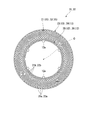
- FIG. 2 is a side view of the tire when the non-pneumatic tire shown in FIG. 1 is viewed from the outside of the vehicle body in the tire width direction. It is an enlarged view which shows the principal part of FIG.
- FIG. 1 is a tire side view of the first divided case body viewed from the outside of the vehicle body in the tire width direction.
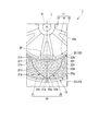
- the non-pneumatic tire 1 of the present embodiment includes an attachment body 11 attached to an axle (not shown), and a cylindrical ring-like body 13 surrounding the attachment body 11 from the outside in the tire radial direction.
- a plurality of outer cylinders are disposed between the attachment body 11 and the ring-shaped body 13 along the tire circumferential direction, and the attachment body 11 and the ring-shaped body 13 are connected to each other so as to be relatively elastically displaceable.
- a cylindrical tread member 16 externally mounted on the ring-shaped body 13.
- the non-pneumatic tire 1 of the present embodiment may be used for a two-wheeled vehicle such as a bicycle, may run with a camber angle of about 30 degrees, and is defined in Japanese Industrial Standard JIS T 9208. You may use for a small vehicle etc. which drive
- the mounting body 11, the ring-shaped body 13, and the tread member 16 described above are disposed coaxially with the common shaft.
- the common axis is referred to as an axis O
- a direction along the axis O is referred to as a tire width direction H
- a direction orthogonal to the axis O is referred to as a tire radial direction
- a direction around the axis O is referred to as a tire circumferential direction.
- the attachment body 11, the ring-shaped body 13, and the tread member 16 are arrange
- the outer diameter of the ring-shaped body 13 is the same regardless of the position in the tire circumferential direction.
- the attachment body 11 connects the mounting cylinder part 17 to which the front end part of the axle is mounted, the outer ring part 18 surrounding the mounting cylinder part 17 from the outer side in the tire radial direction, and the mounting cylinder part 17 and the outer ring part 18.
- a plurality of ribs 19 are integrally formed of a metal material such as an aluminum alloy.
- the mounting cylinder portion 17 and the outer ring portion 18 are each formed in a cylindrical shape and are arranged coaxially with the axis O.
- the plurality of ribs 19 are arranged, for example, at equal intervals in the circumferential direction.
- a plurality of key groove portions 18a that are recessed toward the inside in the tire radial direction and that extend in the tire width direction H are formed on the outer peripheral surface of the outer ring portion 18 at intervals in the tire circumferential direction.
- the key groove portion 18 a opens only on the outer side (one side) of the vehicle body in the tire width direction H on the outer peripheral surface of the outer ring portion 18, and is closed on the inner side (the other side) of the vehicle body in the tire width direction H.
- a lightening hole 18 b that penetrates the outer ring portion 18 in the tire radial direction is spaced apart in the tire width direction H.
- a plurality are formed.
- a plurality of hole rows 18c constituted by the plurality of lightening holes 18b are formed at intervals in the tire circumferential direction.
- each rib 19 is formed with a lightening hole 19a that penetrates the rib 19 in the tire width direction H.
- a concave portion 18d into which a plate material 28 having a through hole 28a is fitted is formed at an end of the outer ring portion 18 on the outer side of the vehicle body in the tire width direction H at a position corresponding to the key groove portion 18a.
- the recess 18d is recessed toward the inside of the vehicle body in the tire width direction H.
- a female screw portion communicating with the through hole 28a of the plate member 28 fitted in the concave portion 18d is formed on the wall surface facing the vehicle body outside in the tire width direction H among the wall surfaces defining the concave portion 18d.
- a plurality of through-holes 28a are formed in the plate material 28 at intervals in the tire circumferential direction.
- a plurality of female thread portions are formed on the wall surface of the recess 18d at intervals in the tire circumferential direction.
- a case where two through holes 28a and two female screw portions are formed is shown, but the number is not limited to two.
- a cylindrical exterior body 12 is fitted on the attachment body 11.
- a ridge portion 12 a that protrudes toward the inner side in the tire radial direction and extends over the entire length in the tire width direction H is formed.
- a plurality of protrusions 12 a are formed on the inner peripheral surface of the exterior body 12 at intervals in the tire circumferential direction, and are respectively fitted to key groove portions 18 a formed on the attachment body 11. Then, the exterior body 12 is attached by screwing a bolt (not shown) to the female screw portion through the through hole 28a of the plate member 28 fitted in the recess 18d in a state where the protrusion 12a is fitted in the key groove portion 18a. It is fixed to the body 11.
- the pair of side wall surfaces and the bottom wall surface facing each other in the tire circumferential direction are formed to be orthogonal to each other.
- the pair of side wall surfaces rising from the inner peripheral surface of the exterior body 12 and the top wall surface facing the inner side in the tire radial direction in the outer surface of the protrusion 12a are also formed to be orthogonal to each other.
- size of the tire circumferential direction of the protrusion part 12a and the keyway part 18a is mutually made equivalent. With such a configuration, the protruding portion 12a is fitted with high accuracy in the key groove portion 18a with less rattling.
- the connecting member 15 connects the outer peripheral surface side of the attachment body 11 and the inner peripheral surface side of the ring-shaped body 13 so as to be relatively elastically displaceable.
- the connecting member 15 includes a first connecting plate 21 and a second connecting plate 22 that connect the outer peripheral surface of the exterior body 12 fitted on the attachment body 11 and the inner peripheral surface of the ring-shaped body 13 to each other. ing. Both the first connecting plate 21 and the second connecting plate 22 are elastically deformable plates.
- a plurality of first connecting plates 21 are arranged along the tire circumferential direction at positions outside the vehicle body along the tire width direction H.
- a plurality of second connecting plates 22 are arranged along the tire circumferential direction at positions inside the vehicle body along the tire width direction H. That is, the 1st connection board 21 and the 2nd connection board 22 are arrange
- the plurality of connecting members 15 are respectively arranged between the exterior body 12 and the ring-shaped body 13 at positions that are rotationally symmetric with respect to the axis O. Further, all the connecting members 15 have the same shape and the same size, and the width of the connecting member 15 along the tire width direction H is smaller than the width of the ring-shaped body 13 along the tire width direction H.
- the first connecting plates 21 adjacent in the tire circumferential direction are not in contact with each other.
- the second connecting plates 22 adjacent in the tire circumferential direction are also not in contact with each other.
- the first connecting plate 21 and the second connecting plate 22 that are adjacent in the tire width direction H are also not in contact with each other.
- the first connecting plate 21 and the second connecting plate 22 have the same width and thickness along the tire width direction H.
- the outer end (one end) 21 a connected to the ring-shaped body 13 is more than the inner end (other end) 21 b connected to the exterior body 12. Is also located on one side in the tire circumferential direction.
- the outer end portion (one end portion) 22 a connected to the ring-shaped body 13 is a tire than the inner end portion (other end portion) 22 b connected to the exterior body 12. It is located on the other side in the circumferential direction.
- the outer end portions 21a and 22a of the first connecting plate 21 and the second connecting plate 22 constituting one connecting member 15 are located at different positions in the tire width direction H on the inner peripheral surface of the ring-shaped body 13. In this state, they are connected to the same position in the tire circumferential direction.
- the first connecting plate 21 and the second connecting plate 22 have curved portions 21d to 21f, 22d that are curved in the tire circumferential direction at intermediate portions located between the outer end portions 21a, 22a and the inner end portions 21b, 22b.
- a plurality of .about.22f are formed.
- the plurality of curved portions 21d to 21f and 22d to 22f are formed along the direction in which the first connecting plate 21 and the second connecting plate 22 extend in a side view of the non-pneumatic tire 1 as viewed from the tire width direction H.
- the first connecting plate 21 and the second connecting plate 22 extend from the plurality of bent portions 21d to 21f in the first connecting plate 21 and the plurality of bent portions 22d to 22f in the second connecting plate 22, respectively.
- the directions are adjacent to each other, and the bending directions are opposite to each other.
- the plurality of curved portions 21d to 21f formed on the first connecting plate 21 are a first curved portion 21d curved so as to protrude toward the other side in the tire circumferential direction, a first curved portion 21d, and an outer end portion. Between the first curved portion 21d and the inner end portion 21b, and a second curved portion 21e that is curved so as to project toward one side in the tire circumferential direction, And a third curved portion 21f that is curved so as to project toward one side in the tire circumferential direction.
- the second bending portion 21e is continuous with the outer end portion 21a.
- the plurality of curved portions 22d to 22f formed on the second connecting plate 22 are a first curved portion 22d curved so as to project toward one side in the tire circumferential direction, a first curved portion 22d, and an outer end portion. 22a, a second curved portion 22e that is curved so as to protrude toward the other side in the tire circumferential direction, a first curved portion 22d, and an inner end portion 22b, and A third curved portion 22f that is curved so as to project toward the other side in the tire circumferential direction.
- the second bending portion 22e is continuous with the outer end portion 22a.
- the first bending portions 21d and 22d are formed to have a larger radius of curvature in a tire side view than the second bending portions 21e and 22e and the third bending portions 21f and 22f. It arrange
- the lengths of the first connecting plate 21 and the second connecting plate 22 are equal to each other.
- the inner end portions 21b and 22b of the first connecting plate 21 and the second connecting plate 22 are axial O from the position facing the outer end portions 21a and 22a in the tire radial direction on the outer peripheral surface of the exterior body 12 in a side view of the tire. Are connected to the one side and the other side in the tire circumferential direction at the same distance from each other. Specifically, a line connecting the outer end portion 21a and the inner end portion 21b of the first connecting plate 21 and a line connecting the outer end portion 22a and the inner end portion 22b of the second connecting plate 22 are formed.
- the inner ends 21 b and 22 b of the first connecting plate 21 and the second connecting plate 22 are connected to the outer peripheral surface of the exterior body 12 so that the angle is, for example, an angle of 20 ° to 135 °. Further, the first curved portions 21d and 22d, the second curved portions 21e and 22e, and the third curved portions 21f and 22f of the first connecting plate 21 and the second connecting plate 22 respectively protrude in the tire circumferential direction. Are opposite in direction and equal in size.
- each connecting member 15 in the side view of the tire extends along the tire radial direction as shown in FIG. 3, and each outer end portion of the first connecting plate 21 and the second connecting plate 22.
- the imaginary line L passing through 21a and 22a is symmetric with respect to the axis of symmetry.
- the exterior body 12, the ring-shaped body 13, and the plurality of connecting members 15 described above are integrally formed of, for example, a synthetic resin material.
- the synthetic resin material may be, for example, only one type of resin material, a mixture containing two or more types of resin materials, or a mixture containing one or more types of resin materials and one or more types of elastomers. You may contain additives, such as an anti-aging agent, a plasticizer, a filler, or a pigment.
- the exterior body 12 includes a first exterior body 25 located outside the vehicle body in the tire width direction H and a second exterior body 26 located inside the vehicle body in the tire width direction H. It is divided.
- the ring-shaped body 13 includes a first ring-shaped body 23 (divided cylinder) located on the outer side of the vehicle body in the tire width direction H and a second ring-shaped body 24 (divided cylinder) located on the inner side of the vehicle body in the tire width direction H. ) And are divided.
- the ring-shaped body 13 is formed by connecting ends in the tire width direction H of the first and second ring-shaped bodies 23 and 24 (a plurality of divided cylinders) arranged adjacent to each other in the tire width direction H. .
- the exterior body 12 and the ring-shaped body 13 are each divided at the center in the tire width direction H.
- the 1st exterior body 25 and the 1st ring-shaped body 23 are integrally formed by the 1st connection board 21 and injection molding, as FIG. 4 shows.
- the second exterior body 26 and the second ring body 24 are integrally formed with the second connecting plate 22 by injection molding.
- the unit in which the first exterior body 25, the first ring body 23, and the first connecting plate 21 are integrally formed is referred to as a first divided case body 31, and the second exterior body 26, the second ring body 24, and the like.
- a unit in which the second connecting plate 22 is integrally formed is referred to as a second divided case body 32.
- Each of the divided case bodies 31 and 32 is integrally formed by injection molding in which a molding material is injected from the connecting member 15 side toward the ring-shaped body 13 side.
- a molding material is injected from the connecting member 15 side toward the ring-shaped body 13 side.
- the first divided case body 31 as an example, as a mold, an inner space for molding the first exterior body 25, an outer space for molding the first ring-shaped body 23, and an intermediate space for molding the first connecting plate 21.
- a gate for the cavity is connected to the inner space.
- the first divided case body 31 is formed by injecting a molding material from the gate into the cavity and supplying the molding material from the inner space to the outer space through the intermediate space.
- the molding material that has passed through each portion forming the first connecting plate 21 adjacent in the tire circumferential direction flows so as to approach each other in the tire circumferential direction in the outer space based on the injection pressure.
- a weld is formed at a portion sandwiched in the tire circumferential direction between the outer end portions 21a of the first connecting plates 21 adjacent in the tire circumferential direction.
- the first ring-shaped body 23 and the second ring-shaped body 24 have end edges facing each other in the tire width direction H connected to each other by, for example, welding, fusing, adhesion, or the like.
- a joint portion (not shown) formed by connecting ends of the second ring-shaped bodies 23 and 24 in the tire width direction H to each other is provided. In the case of welding, for example, hot plate welding or the like may be performed.
- the first exterior body 25 and the second exterior body 26 are in contact with each other at edges facing each other in the tire width direction H.
- the first divided case body 31 and the second divided case body 32 have the same shape and the same size as shown in FIG. And when connecting the 1st division
- the body 31 and the second divided case body 32 are aligned in the tire circumferential direction. Further, in the state where the directions of the first divided case body 31 and the second divided case body 32 are opposite to each other in the tire width direction H, the first ring-shaped body 23 and the second ring-shaped body 24 in the tire width direction H End edges are connected to each other. Then, the non-pneumatic tire 1 can be obtained by providing the tread member 16 for the first divided case body 31 and the second divided case body 32 combined together.
- the tread member 16 is formed in a cylindrical shape and integrally covers the outer peripheral surface side of the ring-shaped body 13 over the entire area.
- the inner diameter of the tread member 16 is the same over the entire circumference, and the inner circumferential surface of the tread member 16 is in close contact with the outer circumferential surface of the ring-shaped body 13 over the entire area.
- the inner diameter of the tread member 16 is a distance along the tire radial direction between the inner peripheral surface of the tread member 16 and the axis O.
- the outer peripheral surface of the tread member 16 is formed in a perfect circle shape in a cross-sectional view along an orthogonal plane orthogonal to the axis O, and the outer diameter of the tread member 16 is the same over the entire periphery.
- the outer diameter of the tread member 16 is a distance along the tire radial direction between the outer peripheral surface of the tread member 16 and the axis O.
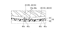
- the tread member 16 includes a base rubber portion 41 located on the inner side in the tire radial direction and a cap rubber portion 42 located on the outer side in the tire radial direction from the base rubber portion 41. . Both the base rubber part 41 and the cap rubber part 42 extend over the entire circumference of the ring-shaped body 13, and the tread member 16 has a two-layer structure of the base rubber part 41 and the cap rubber part 42.
- the base rubber portion 41 is disposed at least in a portion (a portion where a weld is formed) located between the connecting members 15 adjacent in the tire circumferential direction in the ring-shaped body 13, and in the illustrated example, as described above. It extends over the entire circumference of the ring-shaped body 13.
- a part (hereinafter referred to as “weld protection part”) 41 a located between the connecting members 15 adjacent in the tire circumferential direction on the outer peripheral surface of the ring-shaped body 13 is more than the other part. It is also thick and formed large in the tire radial direction.
- the portion located between the connecting members 15 adjacent in the tire circumferential direction is the tire circumferential direction in the first ring-shaped body 23 (or the second ring-shaped body 24).
- the weld protection portion 41a has a curved surface shape that protrudes outward in the tire radial direction in a cross-sectional view along an orthogonal plane orthogonal to the axis O.
- the curvature of the outer surface 41b facing the outer side in the tire radial direction in the weld protection portion 41a is larger than the curvature of the outer peripheral surface of the tread member 16.
- the thickness (the size in the tire radial direction) of the excluded portion that is a portion other than the weld protection portion 41a is the same regardless of the position in the tire radial direction.
- the width in the tire circumferential direction of the weld protection part 41a of the base rubber part 41 is A and the distance between the weld protection parts 41a in the tire circumferential direction is B, the distance B between the weld protection parts 41a is the weld protection part 41a. It is longer than the width A.
- the cap rubber part 42 covers the base rubber part 41 from the outer side in the tire radial direction over the entire circumference, and the base rubber part 41 is not exposed to the outer side in the tire radial direction.
- the outer peripheral surface of the cap rubber portion 42 constitutes the outer peripheral surface of the tread member 16.
- the base rubber part 41 and the cap rubber part 42 are made of two different types of rubber.
- the base rubber portion 41 and the cap rubber portion 42 are formed of vulcanized rubber obtained by vulcanizing natural rubber or / and a rubber composition.
- the rigidity of the base rubber part 41 is lower than the rigidity of the cap rubber part 42.
- the rubber hardness Gb of the base rubber portion 41 is lower than the rubber hardness Gc of the cap rubber portion 42.
- the rubber hardness Gb of the base rubber portion 41 and the rubber hardness Gc of the cap rubber portion 42 satisfy 30 ⁇ Gb ⁇ Gc ⁇ 80.
- the rubber hardness Japanese Industrial Standard JIS-A hardness
- the elastic modulus Eb of the base rubber portion 41 is lower than the elastic modulus Ec of the cap rubber portion 42.
- the elastic modulus Eb of the base rubber part 41 and the elastic modulus Ec of the cap rubber part 42 satisfy 0.1 MPa ⁇ Eb ⁇ Ec ⁇ 100 MPa.
- the elastic modulus was measured with a tensile tester in accordance with Japanese Industrial Standard JIS K 6254: 2010.
- the rigidity of the base rubber portion 41 located on the inner side in the tire radial direction is the rigidity of the cap rubber portion 42 located on the outer side in the tire radial direction. Therefore, the stress generated in the tread member 16 when the load is applied to the tread member 16 can be dispersed in the base rubber portion 41. And since the base rubber part 41 is arrange
- the cap rubber portion 42 having high rigidity is located on the outer side in the tire radial direction with respect to the base rubber portion 41 having low rigidity, the cap rubber portion 42 provides the wear resistance and impact resistance of the tread member 16.
- the running stability of the non-pneumatic tire 1 can also be ensured. As described above, it is possible to ensure the wear resistance and impact resistance of the tread member 16 by the cap rubber portion 42 while suppressing the stress transmitted to the weld by the base rubber portion 41, and non-pneumatic. The strength of the tire 1 can be improved.
- the base rubber portion 41 extends over the entire circumference on the outer peripheral surface of the ring-shaped body 13, and the weld protection portion 41a of the base rubber portion 41 is thicker than the other portions, stress is applied to the weld protection portion 41a. It can be effectively dispersed over a wide range in the tire circumferential direction.
- the rubber hardness Gb of the base rubber portion 41 is lower than the rubber hardness Gc of the cap rubber portion 42, the stress generated in the tread member 16 can be effectively dispersed in the base rubber portion 41. Further, since the rubber hardness Gb of the base rubber portion 41 and the rubber hardness Gc of the cap rubber portion 42 satisfy 30 ⁇ Gb ⁇ Gc ⁇ 80, the stress generated in the tread member 16 is more effectively dispersed in the base rubber portion 41. Can be made.
- the elastic modulus Eb of the base rubber part 41 is lower than the elastic modulus Ec of the cap rubber part 42, the stress generated in the tread member 16 can be effectively dispersed in the base rubber part 41. Furthermore, since the elastic modulus Eb of the base rubber portion 41 and the elastic modulus Ec of the cap rubber portion 42 satisfy 0.1 MPa ⁇ Eb ⁇ Ec ⁇ 100 MPa, the stress generated in the tread member 16 is more effective in the base rubber portion 41. Can be dispersed.
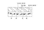
- the base rubber portion 41 is disposed only in a portion of the ring-shaped body 13 located between the connecting members 15 adjacent in the tire circumferential direction.
- a plurality of base rubber portions 41 are intermittently arranged in the tire circumferential direction.
- the base rubber portion 41 has a curved surface shape protruding toward the outer side in the tire radial direction in a cross-sectional view along an orthogonal plane orthogonal to the axis O.
- the curvature of the outer surface of the base rubber portion 41 facing outward in the tire radial direction is larger than the curvature of the outer peripheral surface of the tread member 16.
- connection plate 21 and the 2nd connection plate 22 each as the connection member 15 were shown, it replaces with this and the 1st connection plate 21 and the one connection member 15 are provided.
- a plurality of second connection plates 22 may be provided, each having a different position in the tire width direction H.
- a plurality of connecting members 15 may be provided along the tire width direction H between the exterior body 12 and the ring-shaped body 13.
- the inner end portions 21b and 22b of the first connecting plate 21 and the second connecting plate 22 are opposite to each other with the axis O sandwiched in the tire radial direction on the outer peripheral surface of the exterior body 12, for example, instead of the above embodiment. You may connect with each position, respectively.
- the inner end portions 21 b and 22 b of the first connecting plate 21 and the second connecting plate 22 are connected to the outer end portions 21 a and 22 a of the first connecting plate 21 and the second connecting plate 22 on the outer peripheral surface of the exterior body 12. You may connect with the position etc. which oppose in a tire radial direction.
- the outer end portions 21a and 22a of the first connecting plate 21 and the second connecting plate 22 are connected to the inner peripheral surface of the ring-shaped body 13 at different positions in the tire circumferential direction. May be.
- a gap in the tire width direction H may or may not be provided between the first exterior body 25 and the second exterior body 26.
- the exterior body 12 and the ring-shaped body 13 may be divided into three or more in the tire width direction H, or may not be divided.
- the exterior body 12 and the attachment body 11 integrally. That is, the exterior body 12 may be included in the attachment body 11. Furthermore, in embodiment mentioned above, although it was set as the structure which connects the connection member 15 to the attachment body 11 via the exterior body 12, it is not limited to this. For example, the connection member 15 may be directly connected to the attachment body 11.
- the non-pneumatic tire 1 shown in FIGS. 1 to 5 is used as an example, and the tread member 16 is a single layer made of the same material as the cap rubber portion 42 in the non-pneumatic tire 1 of the example as a comparative example.
- a non-pneumatic tire having a structure was used.
- the thickness of the ring-shaped body 13 of these non-pneumatic tires is H1
- the thickness of the excluded portion of the base rubber portion 41 is H2a
- the thickness of the weld protection portion 41a of the base rubber portion 41 is as follows.
- the thickness of H2b and the cap rubber part 42 is set to H3.
- the thickness H1 of the ring-shaped body 13 is larger than the thickness H2a of the excluded portion of the base rubber portion 41, the thickness H2b of the weld protection portion 41a of the base rubber portion 41, and the thickness H3 of the cap rubber portion 42, that is, H1.
- the relationship of> H2a, H2b, and H3 is established.
- the thickness H1 of the ring-shaped body 13 is equal to or greater than the sum of the thickness H2a of the excluded portion of the base rubber portion 41 and the thickness H3 of the cap rubber portion 42, or weld protection of the base rubber portion 41.
- H1 ⁇ H2a + H3 or H1 ⁇ H2b + H3 is established which is equal to or greater than the sum of the thickness H2b of the portion 41a and the thickness H3 of the cap rubber portion 42.
- the outer diameters of these non-pneumatic tires and the dimensions of H1, H2a, H2b, and H3 were all set to the sizes shown in Table 1 below.
- the unit of the value described in the second line of Table 1 is mm.
- the rubber hardness and elastic modulus of each of the base rubber part 41 and the cap rubber part 42 in the non-pneumatic tire 1 of the example were set to the sizes shown in Table 2 below.
- the strength of the non-pneumatic tire can be improved.
- Non-pneumatic tire 11 Attachment body 13 Ring-shaped body (outer cylinder) 15 Connecting member 16 Tread member 41 Base rubber part 42 Cap rubber part
Landscapes
- Engineering & Computer Science (AREA)
- Mechanical Engineering (AREA)
- Tires In General (AREA)
Abstract
Priority Applications (4)
| Application Number | Priority Date | Filing Date | Title |
|---|---|---|---|
| EP16737238.2A EP3246180B1 (fr) | 2015-01-15 | 2016-01-05 | Roue non pneumatique |
| CN201680005807.1A CN107206841B (zh) | 2015-01-15 | 2016-01-05 | 非充气轮胎 |
| US15/543,066 US20180001699A1 (en) | 2015-01-15 | 2016-01-05 | Non-pneumatic tire |
| JP2016569306A JP6727135B2 (ja) | 2015-01-15 | 2016-01-05 | 非空気入りタイヤ |
Applications Claiming Priority (2)
| Application Number | Priority Date | Filing Date | Title |
|---|---|---|---|
| JP2015-005720 | 2015-01-15 | ||
| JP2015005720 | 2015-01-15 |
Publications (1)
| Publication Number | Publication Date |
|---|---|
| WO2016114167A1 true WO2016114167A1 (fr) | 2016-07-21 |
Family
ID=56405714
Family Applications (1)
| Application Number | Title | Priority Date | Filing Date |
|---|---|---|---|
| PCT/JP2016/050091 WO2016114167A1 (fr) | 2015-01-15 | 2016-01-05 | Pneu non pneumatique |
Country Status (5)
| Country | Link |
|---|---|
| US (1) | US20180001699A1 (fr) |
| EP (1) | EP3246180B1 (fr) |
| JP (1) | JP6727135B2 (fr) |
| CN (1) | CN107206841B (fr) |
| WO (1) | WO2016114167A1 (fr) |
Cited By (8)
| Publication number | Priority date | Publication date | Assignee | Title |
|---|---|---|---|---|
| JP2018079886A (ja) * | 2016-11-18 | 2018-05-24 | 株式会社ブリヂストン | 非空気入りタイヤおよび二輪車 |
| US10166732B2 (en) | 2013-06-15 | 2019-01-01 | Camso Inc. | Annular ring and non-pneumatic tire |
| CN109963727A (zh) * | 2016-11-21 | 2019-07-02 | 株式会社普利司通 | 非充气轮胎和二轮车 |
| CN111344161A (zh) * | 2017-11-10 | 2020-06-26 | 株式会社普利司通 | 非充气轮胎 |
| US10953696B2 (en) | 2015-02-04 | 2021-03-23 | Camso Inc | Non-pneumatic tire and other annular devices |
| US11179969B2 (en) | 2017-06-15 | 2021-11-23 | Camso Inc. | Wheel comprising a non-pneumatic tire |
| EP4019278A1 (fr) | 2020-12-28 | 2022-06-29 | Toyo Tire Corporation | Pneu non pneumatique |
| US11999419B2 (en) | 2015-12-16 | 2024-06-04 | Camso Inc. | Track system for traction of a vehicle |
Families Citing this family (9)
| Publication number | Priority date | Publication date | Assignee | Title |
|---|---|---|---|---|
| JPWO2017006551A1 (ja) * | 2015-07-03 | 2018-04-19 | 株式会社ブリヂストン | タイヤ |
| CA3112804A1 (fr) * | 2018-09-14 | 2020-03-19 | Camso Inc. | Pneu non pneumatique pour un vehicule a carrossage dirige ou pour un autre vehicule |
| JP7329536B2 (ja) * | 2018-11-22 | 2023-08-18 | 株式会社ブリヂストン | タイヤ |
| JP7123771B2 (ja) * | 2018-11-30 | 2022-08-23 | 株式会社ブリヂストン | 非空気入りタイヤ |
| WO2020142665A1 (fr) * | 2019-01-04 | 2020-07-09 | Bridgestone Americas Tire Operations, Llc | Bande de roulement de pneu comportant une couche de bande |
| KR102103781B1 (ko) * | 2019-06-10 | 2020-04-23 | 김민수 | 에어리스 휠 |
| JP2020199954A (ja) | 2019-06-12 | 2020-12-17 | 株式会社ブリヂストン | 非空気入りタイヤ、移動体給電装置及び移動体 |
| CN111003212A (zh) * | 2019-12-20 | 2020-04-14 | 北京工业大学 | 一种形状记忆合金点阵结构的火星轮胎 |
| AU2022329736A1 (en) * | 2021-08-17 | 2023-12-07 | Briggs And Riley Travelware, Llc | Shock absorbing luggage wheel |
Citations (3)
| Publication number | Priority date | Publication date | Assignee | Title |
|---|---|---|---|---|
| JPS6018407A (ja) * | 1984-06-20 | 1985-01-30 | Sumitomo Rubber Ind Ltd | ソリツドタイヤ |
| JP2012035792A (ja) * | 2010-08-09 | 2012-02-23 | Toyo Tire & Rubber Co Ltd | 非空気圧タイヤ |
| JP2014091453A (ja) * | 2012-11-05 | 2014-05-19 | Bridgestone Corp | 非空気入りタイヤ |
Family Cites Families (8)
| Publication number | Priority date | Publication date | Assignee | Title |
|---|---|---|---|---|
| JPS5436365B2 (fr) * | 1971-11-10 | 1979-11-08 | ||
| JPS59128001A (ja) * | 1983-01-12 | 1984-07-24 | Sumitomo Rubber Ind Ltd | ソリツドタイヤ |
| US8109308B2 (en) * | 2007-03-27 | 2012-02-07 | Resilient Technologies LLC. | Tension-based non-pneumatic tire |
| US9662939B2 (en) * | 2009-07-28 | 2017-05-30 | Bridgestone Americas Tire Operations, Llc | Tension-based non-pneumatic tire |
| KR101116869B1 (ko) * | 2009-12-02 | 2012-03-06 | 한국타이어 주식회사 | 자기유변형 비공기식 타이어 |
| CN202378621U (zh) * | 2011-12-21 | 2012-08-15 | 陕西重型汽车有限公司 | 蜂巢状非充气式轮胎总成 |
| CN202518038U (zh) * | 2012-01-12 | 2012-11-07 | 周文州 | 免充气防爆轮胎 |
| CN203078232U (zh) * | 2013-01-17 | 2013-07-24 | 齐效荣 | 不充气钢结构内置橡胶结构内网状轮胎 |
-
2016
- 2016-01-05 WO PCT/JP2016/050091 patent/WO2016114167A1/fr active Application Filing
- 2016-01-05 CN CN201680005807.1A patent/CN107206841B/zh active Active
- 2016-01-05 US US15/543,066 patent/US20180001699A1/en not_active Abandoned
- 2016-01-05 EP EP16737238.2A patent/EP3246180B1/fr active Active
- 2016-01-05 JP JP2016569306A patent/JP6727135B2/ja active Active
Patent Citations (3)
| Publication number | Priority date | Publication date | Assignee | Title |
|---|---|---|---|---|
| JPS6018407A (ja) * | 1984-06-20 | 1985-01-30 | Sumitomo Rubber Ind Ltd | ソリツドタイヤ |
| JP2012035792A (ja) * | 2010-08-09 | 2012-02-23 | Toyo Tire & Rubber Co Ltd | 非空気圧タイヤ |
| JP2014091453A (ja) * | 2012-11-05 | 2014-05-19 | Bridgestone Corp | 非空気入りタイヤ |
Cited By (13)
| Publication number | Priority date | Publication date | Assignee | Title |
|---|---|---|---|---|
| US10166732B2 (en) | 2013-06-15 | 2019-01-01 | Camso Inc. | Annular ring and non-pneumatic tire |
| US11014316B2 (en) | 2013-06-15 | 2021-05-25 | Camso Inc. | Annular ring and non-pneumatic tire |
| US10953696B2 (en) | 2015-02-04 | 2021-03-23 | Camso Inc | Non-pneumatic tire and other annular devices |
| US11999419B2 (en) | 2015-12-16 | 2024-06-04 | Camso Inc. | Track system for traction of a vehicle |
| EP3543036A4 (fr) * | 2016-11-18 | 2019-09-25 | Bridgestone Corporation | Pneu non pneumatique et véhicule à deux roues |
| JP2018079886A (ja) * | 2016-11-18 | 2018-05-24 | 株式会社ブリヂストン | 非空気入りタイヤおよび二輪車 |
| EP3543040A4 (fr) * | 2016-11-21 | 2019-10-30 | Bridgestone Corporation | Pneu non pneumatique et véhicule à deux roues |
| CN109963727A (zh) * | 2016-11-21 | 2019-07-02 | 株式会社普利司通 | 非充气轮胎和二轮车 |
| US11179969B2 (en) | 2017-06-15 | 2021-11-23 | Camso Inc. | Wheel comprising a non-pneumatic tire |
| CN111344161A (zh) * | 2017-11-10 | 2020-06-26 | 株式会社普利司通 | 非充气轮胎 |
| CN111344161B (zh) * | 2017-11-10 | 2022-03-22 | 株式会社普利司通 | 非充气轮胎 |
| US11654716B2 (en) | 2017-11-10 | 2023-05-23 | Bridgestone Corporation | Nonpneumatic tire |
| EP4019278A1 (fr) | 2020-12-28 | 2022-06-29 | Toyo Tire Corporation | Pneu non pneumatique |
Also Published As
| Publication number | Publication date |
|---|---|
| CN107206841B (zh) | 2019-12-27 |
| JPWO2016114167A1 (ja) | 2017-10-26 |
| CN107206841A (zh) | 2017-09-26 |
| EP3246180B1 (fr) | 2019-06-26 |
| EP3246180A1 (fr) | 2017-11-22 |
| US20180001699A1 (en) | 2018-01-04 |
| EP3246180A4 (fr) | 2018-03-14 |
| JP6727135B2 (ja) | 2020-07-22 |
Similar Documents
| Publication | Publication Date | Title |
|---|---|---|
| WO2016114167A1 (fr) | Pneu non pneumatique | |
| JP6727136B2 (ja) | 非空気入りタイヤ | |
| WO2016098477A1 (fr) | Pneu non pneumatique | |
| JP6061625B2 (ja) | 非空気入りタイヤ | |
| JP6152036B2 (ja) | 非空気入りタイヤ | |
| WO2013058389A1 (fr) | Bandage non pneumatique | |
| WO2016072181A1 (fr) | Pneu non pneumatique | |
| JP6505667B2 (ja) | 非空気入りタイヤ | |
| WO2016148295A1 (fr) | Pneu non-pneumatique | |
| WO2015072312A1 (fr) | Pneu non pneumatique | |
| WO2014103721A1 (fr) | Pneu non pneumatique | |
| WO2014103723A1 (fr) | Pneu non pneumatique | |
| WO2014103680A1 (fr) | Pneu non pneumatique | |
| JP6106428B2 (ja) | 非空気入りタイヤ | |
| WO2016084512A1 (fr) | Pneu non pneumatique | |
| WO2015052989A1 (fr) | Pneu non pneumatique | |
| WO2015052987A1 (fr) | Pneu non pneumatique | |
| WO2015072183A1 (fr) | Pneu non pneumatique | |
| WO2015072222A1 (fr) | Pneu non pneumatique | |
| JP2014118128A (ja) | 非空気入りタイヤ | |
| JP2014213789A (ja) | 非空気入りタイヤ | |
| JP2013163517A (ja) | 非空気入りタイヤ | |
| JP6522936B2 (ja) | 非空気入りタイヤ | |
| JP6240972B2 (ja) | 非空気入りタイヤ | |
| JP6240971B2 (ja) | 非空気入りタイヤ |
Legal Events
| Date | Code | Title | Description |
|---|---|---|---|
| 121 | Ep: the epo has been informed by wipo that ep was designated in this application |
Ref document number: 16737238 Country of ref document: EP Kind code of ref document: A1 |
|
| ENP | Entry into the national phase |
Ref document number: 2016569306 Country of ref document: JP Kind code of ref document: A |
|
| WWE | Wipo information: entry into national phase |
Ref document number: 15543066 Country of ref document: US |
|
| REEP | Request for entry into the european phase |
Ref document number: 2016737238 Country of ref document: EP |
|
| NENP | Non-entry into the national phase |
Ref country code: DE |