WO2016111258A1 - ガス液化装置及びガス液化方法 - Google Patents
ガス液化装置及びガス液化方法 Download PDFInfo
- Publication number
- WO2016111258A1 WO2016111258A1 PCT/JP2016/050019 JP2016050019W WO2016111258A1 WO 2016111258 A1 WO2016111258 A1 WO 2016111258A1 JP 2016050019 W JP2016050019 W JP 2016050019W WO 2016111258 A1 WO2016111258 A1 WO 2016111258A1
- Authority
- WO
- WIPO (PCT)
- Prior art keywords
- gas
- heat exchanger
- supply line
- raw material
- refrigerant
- Prior art date
- Legal status (The legal status is an assumption and is not a legal conclusion. Google has not performed a legal analysis and makes no representation as to the accuracy of the status listed.)
- Ceased
Links
Images

Classifications
-
- F—MECHANICAL ENGINEERING; LIGHTING; HEATING; WEAPONS; BLASTING
- F25—REFRIGERATION OR COOLING; COMBINED HEATING AND REFRIGERATION SYSTEMS; HEAT PUMP SYSTEMS; MANUFACTURE OR STORAGE OF ICE; LIQUEFACTION SOLIDIFICATION OF GASES
- F25J—LIQUEFACTION, SOLIDIFICATION OR SEPARATION OF GASES OR GASEOUS OR LIQUEFIED GASEOUS MIXTURES BY PRESSURE AND COLD TREATMENT OR BY BRINGING THEM INTO THE SUPERCRITICAL STATE
- F25J1/00—Processes or apparatus for liquefying or solidifying gases or gaseous mixtures
- F25J1/0002—Processes or apparatus for liquefying or solidifying gases or gaseous mixtures characterised by the fluid to be liquefied
- F25J1/0022—Hydrocarbons, e.g. natural gas
-
- F—MECHANICAL ENGINEERING; LIGHTING; HEATING; WEAPONS; BLASTING
- F25—REFRIGERATION OR COOLING; COMBINED HEATING AND REFRIGERATION SYSTEMS; HEAT PUMP SYSTEMS; MANUFACTURE OR STORAGE OF ICE; LIQUEFACTION SOLIDIFICATION OF GASES
- F25J—LIQUEFACTION, SOLIDIFICATION OR SEPARATION OF GASES OR GASEOUS OR LIQUEFIED GASEOUS MIXTURES BY PRESSURE AND COLD TREATMENT OR BY BRINGING THEM INTO THE SUPERCRITICAL STATE
- F25J1/00—Processes or apparatus for liquefying or solidifying gases or gaseous mixtures
- F25J1/003—Processes or apparatus for liquefying or solidifying gases or gaseous mixtures characterised by the kind of cold generation within the liquefaction unit for compensating heat leaks and liquid production
- F25J1/0032—Processes or apparatus for liquefying or solidifying gases or gaseous mixtures characterised by the kind of cold generation within the liquefaction unit for compensating heat leaks and liquid production using the feed stream itself or separated fractions from it, i.e. "internal refrigeration"
- F25J1/0035—Processes or apparatus for liquefying or solidifying gases or gaseous mixtures characterised by the kind of cold generation within the liquefaction unit for compensating heat leaks and liquid production using the feed stream itself or separated fractions from it, i.e. "internal refrigeration" by gas expansion with extraction of work
-
- F—MECHANICAL ENGINEERING; LIGHTING; HEATING; WEAPONS; BLASTING
- F25—REFRIGERATION OR COOLING; COMBINED HEATING AND REFRIGERATION SYSTEMS; HEAT PUMP SYSTEMS; MANUFACTURE OR STORAGE OF ICE; LIQUEFACTION SOLIDIFICATION OF GASES
- F25J—LIQUEFACTION, SOLIDIFICATION OR SEPARATION OF GASES OR GASEOUS OR LIQUEFIED GASEOUS MIXTURES BY PRESSURE AND COLD TREATMENT OR BY BRINGING THEM INTO THE SUPERCRITICAL STATE
- F25J1/00—Processes or apparatus for liquefying or solidifying gases or gaseous mixtures
- F25J1/003—Processes or apparatus for liquefying or solidifying gases or gaseous mixtures characterised by the kind of cold generation within the liquefaction unit for compensating heat leaks and liquid production
- F25J1/0032—Processes or apparatus for liquefying or solidifying gases or gaseous mixtures characterised by the kind of cold generation within the liquefaction unit for compensating heat leaks and liquid production using the feed stream itself or separated fractions from it, i.e. "internal refrigeration"
- F25J1/0035—Processes or apparatus for liquefying or solidifying gases or gaseous mixtures characterised by the kind of cold generation within the liquefaction unit for compensating heat leaks and liquid production using the feed stream itself or separated fractions from it, i.e. "internal refrigeration" by gas expansion with extraction of work
- F25J1/0037—Processes or apparatus for liquefying or solidifying gases or gaseous mixtures characterised by the kind of cold generation within the liquefaction unit for compensating heat leaks and liquid production using the feed stream itself or separated fractions from it, i.e. "internal refrigeration" by gas expansion with extraction of work of a return stream
-
- F—MECHANICAL ENGINEERING; LIGHTING; HEATING; WEAPONS; BLASTING
- F25—REFRIGERATION OR COOLING; COMBINED HEATING AND REFRIGERATION SYSTEMS; HEAT PUMP SYSTEMS; MANUFACTURE OR STORAGE OF ICE; LIQUEFACTION SOLIDIFICATION OF GASES
- F25J—LIQUEFACTION, SOLIDIFICATION OR SEPARATION OF GASES OR GASEOUS OR LIQUEFIED GASEOUS MIXTURES BY PRESSURE AND COLD TREATMENT OR BY BRINGING THEM INTO THE SUPERCRITICAL STATE
- F25J1/00—Processes or apparatus for liquefying or solidifying gases or gaseous mixtures
- F25J1/003—Processes or apparatus for liquefying or solidifying gases or gaseous mixtures characterised by the kind of cold generation within the liquefaction unit for compensating heat leaks and liquid production
- F25J1/0032—Processes or apparatus for liquefying or solidifying gases or gaseous mixtures characterised by the kind of cold generation within the liquefaction unit for compensating heat leaks and liquid production using the feed stream itself or separated fractions from it, i.e. "internal refrigeration"
- F25J1/004—Processes or apparatus for liquefying or solidifying gases or gaseous mixtures characterised by the kind of cold generation within the liquefaction unit for compensating heat leaks and liquid production using the feed stream itself or separated fractions from it, i.e. "internal refrigeration" by flash gas recovery
-
- F—MECHANICAL ENGINEERING; LIGHTING; HEATING; WEAPONS; BLASTING
- F25—REFRIGERATION OR COOLING; COMBINED HEATING AND REFRIGERATION SYSTEMS; HEAT PUMP SYSTEMS; MANUFACTURE OR STORAGE OF ICE; LIQUEFACTION SOLIDIFICATION OF GASES
- F25J—LIQUEFACTION, SOLIDIFICATION OR SEPARATION OF GASES OR GASEOUS OR LIQUEFIED GASEOUS MIXTURES BY PRESSURE AND COLD TREATMENT OR BY BRINGING THEM INTO THE SUPERCRITICAL STATE
- F25J1/00—Processes or apparatus for liquefying or solidifying gases or gaseous mixtures
- F25J1/02—Processes or apparatus for liquefying or solidifying gases or gaseous mixtures requiring the use of refrigeration, e.g. of helium or hydrogen ; Details and kind of the refrigeration system used; Integration with other units or processes; Controlling aspects of the process
- F25J1/0201—Processes or apparatus for liquefying or solidifying gases or gaseous mixtures requiring the use of refrigeration, e.g. of helium or hydrogen ; Details and kind of the refrigeration system used; Integration with other units or processes; Controlling aspects of the process using only internal refrigeration means, i.e. without external refrigeration
- F25J1/0202—Processes or apparatus for liquefying or solidifying gases or gaseous mixtures requiring the use of refrigeration, e.g. of helium or hydrogen ; Details and kind of the refrigeration system used; Integration with other units or processes; Controlling aspects of the process using only internal refrigeration means, i.e. without external refrigeration in a quasi-closed internal refrigeration loop
-
- F—MECHANICAL ENGINEERING; LIGHTING; HEATING; WEAPONS; BLASTING
- F25—REFRIGERATION OR COOLING; COMBINED HEATING AND REFRIGERATION SYSTEMS; HEAT PUMP SYSTEMS; MANUFACTURE OR STORAGE OF ICE; LIQUEFACTION SOLIDIFICATION OF GASES
- F25J—LIQUEFACTION, SOLIDIFICATION OR SEPARATION OF GASES OR GASEOUS OR LIQUEFIED GASEOUS MIXTURES BY PRESSURE AND COLD TREATMENT OR BY BRINGING THEM INTO THE SUPERCRITICAL STATE
- F25J1/00—Processes or apparatus for liquefying or solidifying gases or gaseous mixtures
- F25J1/02—Processes or apparatus for liquefying or solidifying gases or gaseous mixtures requiring the use of refrigeration, e.g. of helium or hydrogen ; Details and kind of the refrigeration system used; Integration with other units or processes; Controlling aspects of the process
- F25J1/0203—Processes or apparatus for liquefying or solidifying gases or gaseous mixtures requiring the use of refrigeration, e.g. of helium or hydrogen ; Details and kind of the refrigeration system used; Integration with other units or processes; Controlling aspects of the process using a single-component refrigerant [SCR] fluid in a closed vapor compression cycle
-
- F—MECHANICAL ENGINEERING; LIGHTING; HEATING; WEAPONS; BLASTING
- F25—REFRIGERATION OR COOLING; COMBINED HEATING AND REFRIGERATION SYSTEMS; HEAT PUMP SYSTEMS; MANUFACTURE OR STORAGE OF ICE; LIQUEFACTION SOLIDIFICATION OF GASES
- F25J—LIQUEFACTION, SOLIDIFICATION OR SEPARATION OF GASES OR GASEOUS OR LIQUEFIED GASEOUS MIXTURES BY PRESSURE AND COLD TREATMENT OR BY BRINGING THEM INTO THE SUPERCRITICAL STATE
- F25J1/00—Processes or apparatus for liquefying or solidifying gases or gaseous mixtures
- F25J1/02—Processes or apparatus for liquefying or solidifying gases or gaseous mixtures requiring the use of refrigeration, e.g. of helium or hydrogen ; Details and kind of the refrigeration system used; Integration with other units or processes; Controlling aspects of the process
- F25J1/0243—Start-up or control of the process; Details of the apparatus used; Details of the refrigerant compression system used
- F25J1/0279—Compression of refrigerant or internal recycle fluid, e.g. kind of compressor, accumulator, suction drum etc.
- F25J1/0285—Combination of different types of drivers mechanically coupled to the same refrigerant compressor, possibly split on multiple compressor casings
- F25J1/0288—Combination of different types of drivers mechanically coupled to the same refrigerant compressor, possibly split on multiple compressor casings using work extraction by mechanical coupling of compression and expansion of the refrigerant, so-called companders
-
- F—MECHANICAL ENGINEERING; LIGHTING; HEATING; WEAPONS; BLASTING
- F25—REFRIGERATION OR COOLING; COMBINED HEATING AND REFRIGERATION SYSTEMS; HEAT PUMP SYSTEMS; MANUFACTURE OR STORAGE OF ICE; LIQUEFACTION SOLIDIFICATION OF GASES
- F25J—LIQUEFACTION, SOLIDIFICATION OR SEPARATION OF GASES OR GASEOUS OR LIQUEFIED GASEOUS MIXTURES BY PRESSURE AND COLD TREATMENT OR BY BRINGING THEM INTO THE SUPERCRITICAL STATE
- F25J2220/00—Processes or apparatus involving steps for the removal of impurities
- F25J2220/60—Separating impurities from natural gas, e.g. mercury, cyclic hydrocarbons
- F25J2220/64—Separating heavy hydrocarbons, e.g. NGL, LPG, C4+ hydrocarbons or heavy condensates in general
-
- F—MECHANICAL ENGINEERING; LIGHTING; HEATING; WEAPONS; BLASTING
- F25—REFRIGERATION OR COOLING; COMBINED HEATING AND REFRIGERATION SYSTEMS; HEAT PUMP SYSTEMS; MANUFACTURE OR STORAGE OF ICE; LIQUEFACTION SOLIDIFICATION OF GASES
- F25J—LIQUEFACTION, SOLIDIFICATION OR SEPARATION OF GASES OR GASEOUS OR LIQUEFIED GASEOUS MIXTURES BY PRESSURE AND COLD TREATMENT OR BY BRINGING THEM INTO THE SUPERCRITICAL STATE
- F25J2230/00—Processes or apparatus involving steps for increasing the pressure of gaseous process streams
- F25J2230/20—Integrated compressor and process expander; Gear box arrangement; Multiple compressors on a common shaft
-
- F—MECHANICAL ENGINEERING; LIGHTING; HEATING; WEAPONS; BLASTING
- F25—REFRIGERATION OR COOLING; COMBINED HEATING AND REFRIGERATION SYSTEMS; HEAT PUMP SYSTEMS; MANUFACTURE OR STORAGE OF ICE; LIQUEFACTION SOLIDIFICATION OF GASES
- F25J—LIQUEFACTION, SOLIDIFICATION OR SEPARATION OF GASES OR GASEOUS OR LIQUEFIED GASEOUS MIXTURES BY PRESSURE AND COLD TREATMENT OR BY BRINGING THEM INTO THE SUPERCRITICAL STATE
- F25J2245/00—Processes or apparatus involving steps for recycling of process streams
- F25J2245/90—Processes or apparatus involving steps for recycling of process streams the recycled stream being boil-off gas from storage
-
- F—MECHANICAL ENGINEERING; LIGHTING; HEATING; WEAPONS; BLASTING
- F25—REFRIGERATION OR COOLING; COMBINED HEATING AND REFRIGERATION SYSTEMS; HEAT PUMP SYSTEMS; MANUFACTURE OR STORAGE OF ICE; LIQUEFACTION SOLIDIFICATION OF GASES
- F25J—LIQUEFACTION, SOLIDIFICATION OR SEPARATION OF GASES OR GASEOUS OR LIQUEFIED GASEOUS MIXTURES BY PRESSURE AND COLD TREATMENT OR BY BRINGING THEM INTO THE SUPERCRITICAL STATE
- F25J2270/00—Refrigeration techniques used
- F25J2270/04—Internal refrigeration with work-producing gas expansion loop
- F25J2270/06—Internal refrigeration with work-producing gas expansion loop with multiple gas expansion loops
Definitions
- the present invention relates to a gas liquefaction apparatus and a gas liquefaction method for liquefying natural gas as liquefied natural gas, for example.
- a process of liquefying natural gas (NG) as liquefied natural gas (LNG) uses a refrigerant having a specific composition (for example, nitrogen (N 2 ) or a mixed refrigerant), and uses this dedicated refrigerant. Since a so-called closed loop type that circulates as a closed system is employed, there are the following problems as a liquefaction process of small and medium-sized natural gas for which a simple apparatus is preferred.
- Patent Document 1 a technology for an open loop cycle process in which natural gas is directly used as a refrigerant has been proposed.
- an object of the present invention is to provide a gas liquefaction apparatus and a gas liquefaction method that are simple in heat exchange equipment and reduce equipment cost and power.
- a first invention of the present invention for solving the above-described problems includes a raw material gas supply line that supplies a raw material gas, and a room temperature heat exchange that is provided in order in series with the raw material gas supply line and cools the raw material gas.
- the gas component separated by the separation drum is used as a refrigerant gas, and the refrigerant gas is supplied in the order of the liquefaction / supercooling heat exchanger, the precooling heat exchanger, and the room temperature heat exchanger in the supply direction of the raw material gas.
- a refrigerant gas supply line that supplies the gas in a reverse direction and cools the raw material gas, a compressor that is provided at the tip of the refrigerant gas supply line and compresses the refrigerant gas used for cooling, and is compressed by the compressor
- a compressed gas extraction line for extracting the compressed gas from the compressor, and a tip of the compressed gas extraction line is connected upstream of the room temperature heat exchanger of the raw material gas supply line, to the raw material gas
- a gas comprising: an expansion turbine; and a cooling source gas supply line that supplies the cooling source gas cooled by the expansion turbine to the refrig
- a raw material gas supply line for supplying a raw material gas, a room temperature heat exchanger provided in order in series with the raw material gas supply line, for cooling the raw material gas by heat exchange with a refrigerant gas, and preliminary cooling A heat exchanger, a liquefying / supercooling heat exchanger, a separation drum provided at a tip of the raw material gas supply line, which is cooled and separates the raw material gas containing condensate into a gas component and a liquefied component, and the separation A gas component separated and cooled by a drum is used as a refrigerant gas, and the refrigerant gas is reversely supplied to the source gas in the order of the liquefaction / supercooling heat exchanger, the precooling heat exchanger, and the room temperature heat exchanger.
- a refrigerant gas supply line for supplying and cooling the raw material gas; a compressor provided at a tip of the refrigerant gas supply line for compressing the refrigerant gas; and a compressed gas for extracting the compressed gas compressed by the compressor
- An outlet line, a leading end of the compressed gas extraction line is connected to the raw material gas supply line on the upstream side of the room temperature heat exchanger, a mixing unit for mixing the compressed gas with the raw material gas, and the room temperature heat exchange
- a first extraction line that is branched from a source gas supply line between a preheater and the precooling heat exchanger, and extracts a part of the source gas after heat exchange by the room temperature heat exchanger, and the first extraction
- a thermal expansion turbine for adiabatically expanding a part of the extracted raw material gas connected to the tip of the line, and a first cooling source gas cooled by the thermal expansion turbine, the preliminary cooling heat exchanger and the liquefaction / supercooling heat Branched from the first cooling source gas supply line that supplies the
- the liquefaction / supercooling heat exchanger is divided into two units, ie, a liquefaction heat exchanger and a supercooling heat exchanger, and the two liquefaction heat exchangers and A supercooling heat exchanger is provided in series, the first cooling source gas cooled by the thermal expansion turbine is branched into two, and the branched first cooling source gas is divided into a precooling heat exchanger, a liquefied heat exchanger, And a refrigerant gas supply line between the liquefying heat exchanger and the supercooling heat exchanger, respectively.
- a fourth invention is the gas according to any one of the first to third inventions, wherein a cooler for cooling the source gas is provided upstream of the room temperature heat exchanger in the source gas supply line. Located in the liquefaction device.
- a heavy component separator that separates a heavy component from a liquid extracted from a part of the raw material gas. Located in the liquefaction device.
- a sixth invention is characterized in that, in any one of the first to fifth inventions, a boil-off gas supply line for supplying boil-off gas is connected to an upstream side of a compressor connected to the refrigerant gas supply line. In the gas liquefaction device.
- a seventh invention is a gas liquefaction method of an open loop cycle process in which a raw material gas is cooled to a liquefaction temperature, and a gas liquefied product is produced from the cooled gas component and the liquefied component.
- the gas liquefaction method comprises: an adiabatic expansion step for extracting and adiabatic expansion; and a refrigerant gas supply step for supplying the cooling source gas cooled in the adiabatic expansion step to the refrigerant gas.
- the raw material after heat exchange in either one or both of the room temperature heat exchanger and the precooling heat exchanger or between the precooling heat exchanger and the liquefied / supercooled heat exchanger A part of the gas is extracted and a cooling source gas having a lowered temperature is obtained by adiabatic expansion in an expansion turbine.
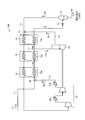
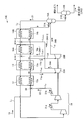
- FIG. 1 is a schematic diagram of a gas liquefying apparatus according to a first embodiment.
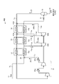
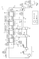
- FIG. 2-1 is a schematic diagram of a gas liquefying apparatus according to a second embodiment.
- FIG. 2-2 is a schematic diagram of a gas liquefying apparatus according to Test Example 1.
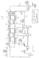
- FIG. 3 is a schematic diagram of a gas liquefying apparatus according to a third embodiment.
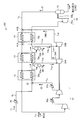
- FIG. 4 is a schematic diagram of a gas liquefying apparatus according to a fourth embodiment.
- FIG. 5A is a schematic diagram of a gas liquefying apparatus according to a fifth embodiment.
- FIG. 5-2 is a schematic diagram of a gas liquefying apparatus according to Test Example 2.
- FIG. 1 is a schematic diagram of a gas liquefying apparatus according to a first embodiment.
- the gas liquefying apparatus 10A according to the present embodiment is provided in order in series with a source gas supply line L 1 for supplying a source gas 11 such as natural gas and a source gas supply line L 1.
- a separation drum 15 that separates a gas component and a liquefied component from a raw material gas 11 containing a liquefied condensate that has been cooled to a liquefaction temperature or lower, a gas component separated by the separation drum 15 as a refrigerant gas 21, and the refrigerant gas 21
- the liquefaction / supercooling heat exchanger 14, the precooling heat exchanger 13 and the room temperature heat exchanger 12 are supplied in the direction opposite to the supply direction of the raw material gas 11, and the raw material gas 11 to be introduced is supplied to each heat exchange unit 12 a, 13a
- the raw material gas 11 is liquefied using, for example, natural gas (NG) containing methane as a main component to form liquefied natural gas (LNG).
- NG natural gas
- LNG liquefied natural gas
- the natural gas pressure is, for example, about 30 to 70 kg / cm 2 supplied by a pipeline.
- it can apply also when liquefying air other than natural gas, for example.
- the source gas supply line L 1 forms a liquefaction line of the supply gas stream for supplying the source gas 11, and the refrigerant gas supply line L 2 for cooling the refrigerant gas stream for supplying the refrigerant gas 21.
- a room temperature heat exchanger 12, a precooling heat exchanger 13, and a liquefaction / supercooling heat exchanger 14 are provided in this order as heat exchanging places.
- the raw material gas 11 supplied by the raw material gas supply line L 1 indirectly cooled by refrigerant gas 21 supplied to face the refrigerant gas supply line L 2 heat exchange portion 12a, 13a, at 14a I am doing so.
- an open loop cycle process is realized in which an unliquefied gas component of the raw material gas 11 is utilized as the refrigerant gas 21 in the end zone of the liquefaction line.
- the room temperature heat exchanger 12, the precooling heat exchanger 13, and the heat exchange units 12a, 13a, and 14a installed inside the liquefying / supercooling heat exchanger 14 are, for example, plate fin type
- the present invention is not limited to this as long as it is a means for efficiently exchanging the raw material gas 11 using the refrigerant gas 21.
- the room temperature heat exchanger 12 exchanges the raw material gas 11 at room temperature (for example, 20 to 40 ° C.) with the refrigerant gas 21 to, for example, about 0 ° C. or 0 ° C. or less.
- the precooling heat exchanger 13 exchanges the raw material gas 11 cooled to near 0 ° C. with the refrigerant gas 21 to, for example, ⁇ 80 ° C. or less.
- the liquefying / supercooling heat exchanger 14 exchanges the raw material gas 11 cooled to ⁇ 80 ° C. or lower with the refrigerant gas 21 to, for example, ⁇ 120 ° C. or lower.
- the cooling temperature in each heat exchanger is a standard, and is appropriately changed according to the composition of the raw material gas 11 and the condition of the refrigerant gas 21.
- the raw material gas 11 cooled by the liquefaction / supercooling heat exchanger 14 is expanded by an expansion valve 51 interposed between the liquefaction / supercooling heat exchanger 14 and the separation drum 15 and then the raw material gas supply line. It is introduced into the separation drum 15 connected to the front end side of L 1 .
- the separation drum 15 separates the flash gas component into the liquefied natural gas component.
- the flash gas Since the flash gas is cooled, it is introduced into the refrigerant gas supply line L 2 as the refrigerant gas 21, and is introduced in the order of the liquefaction / supercooling heat exchanger 14, the precooling heat exchanger 13, and the room temperature heat exchanger 12. And it circulates and utilizes as refrigerant gas which cools raw material gas 11 in each heat exchange part 14a, 13a, and 12a.
- the refrigerant gas 21 used to cool the feed gas 11 is introduced into the compressor 31 provided in the distal end portion of the refrigerant gas supply line L 2.
- the compressor 31 is two-stage compression in this embodiment, but is not limited to this, and two or more stages may be installed. Then, the compressor 31 is compressed to a predetermined pressure (same as the raw material gas), mixed again with the raw material gas 11 in the mixing unit 32, and recirculated.
- the liquefied natural gas (LNG) of the liquefied component separated by the separation drum 15 is collected as a separate product.
- a cooling source gas 34 having a temperature lowered to, for example, ⁇ 150 ° C. or less is obtained by adiabatic expansion.
- the obtained cooling source gas 34 passes between the liquefaction / supercooling heat exchanger 14 upstream of the liquefaction / supercooling heat exchanger 14 and the separation drum 15 via the cooling source gas supply line L 5.
- the refrigerant gas supply line L 2 is combined with the refrigerant gas 21 in the refrigerant junction part 41.
- This cooling source gas 34 is merged into the refrigerant gas 21 at the refrigerant merge section 41, so that the heat exchange capacity required for cooling in the liquefaction / supercooling heat exchanger 14, the precooling heat exchanger 13 and the room temperature heat exchanger 12 is obtained.
- the refrigerant is supplied.
- the source gas 11 having a predetermined pressure (40 k) is supplied from the source gas supply line L 1 to form a supply gas stream.
- the raw material gas supply line L 1 is provided with a room temperature heat exchanger 12, a precooling heat exchanger 13 and a liquefying / supercooling heat exchanger 14 having heat exchange sections 12a, 13a, 14a in the order of flow of the raw material gas 11. ing.
- the gas After expansion by an expansion valve 51 installed in front of the separation drum 15 provided, the gas is separated into a gas component and a liquefied component.
- the liquefied component is sent as liquefied natural gas (LNG) to, for example, a storage tank or a pipeline.
- LNG liquefied natural gas
- the gas component separated by the separation drum 15 Since the gas component separated by the separation drum 15 is cooled, it is sent as refrigerant gas 21 from the top of the separation drum 15 to the refrigerant gas supply line L 2 to form a refrigerant gas stream.
- the refrigerant gas 21 flows in the direction opposite to the supply direction of the raw material gas 11 with the liquefying / supercooling heat exchanger 14, the precooling heat exchanger 13, and the room temperature heat exchanger 12, and each heat exchange section 14a, 13a. , 12a indirectly cools the source gas 11.
- the liquefied component of the raw material gas 11 is separated as liquefied natural gas (LNG), and the unliquefied gas component that is not liquefied is used as the refrigerant gas 21 for cooling.
- the refrigerant gas 21 is sent to the compressor 31 provided in the end zone at the tip of the refrigerant gas supply line L 2 , where it is compressed to the same level as the gas pressure of the raw material gas 11.
- the compressed compressed gas 22 is mixed with the raw material gas 11 in the mixing section 32 and supplied again as the raw material gas 11.
- the obtained cooling source gas 34 passes between the liquefaction / supercooling heat exchanger 14 upstream of the liquefaction / supercooling heat exchanger 14 and the separation drum 15 via the cooling source gas supply line L 5.
- the refrigerant gas supply line L 2 is combined with the refrigerant gas 21 in the refrigerant junction part 41. By this merging, the refrigerant source gas 34 is supplied to the refrigerant gas 21, and the heat exchange amount required for cooling in the liquefying / supercooling heat exchanger 14, the precooling heat exchanger 13, and the room temperature heat exchanger 12 is supplied. I am doing so.
- the power of the compressor 31 is recovered by the power of the expansion turbine 33 connected coaxially so as to reduce the compression power.
- the compressor 31 is provided with coolers 31a and 31b to cool the compressed gas.
- the heat of the room temperature heat exchanger 12, the precooling heat exchanger 13, and the liquefaction / supercooling heat exchanger 14 is arranged so that the raw gas stream line and the refrigerant gas stream line face each other. Since the heat exchanging equipment for exchanging heat in turn at the exchanging portions 12a, 13a, and 14a has a simple configuration, a complicated heat exchanging loop is not required, and equipment costs and power can be reduced.
- the gas liquefaction method of the present invention is an open loop cycle process in which a raw material gas (for example, natural gas) 11 is cooled to a liquefaction temperature and a liquefied natural gas (LNG) of a gas liquefied product is produced from the cooled gas component and the liquefied component.
- a raw material gas for example, natural gas
- LNG liquefied natural gas
- this gas liquefaction manufacturing method at least two heat exchange parts (three heat exchange parts 14a and 13a in this embodiment) are supplied while the cooled gas component is supplied as the refrigerant gas 21 so as to face the raw material gas 11.
- the raw material branched from the raw material gas supply line L 1 between the precooling heat exchanger 13 and the liquefaction / supercooling heat exchanger 14, and the raw material after heat exchange in the precooling heat exchanger 13 is used.
- an extraction line L 4 for extracting a part 11a of the gas 11 is provided, the present invention is not limited to this.
- a line L 4 is provided, sent to the expansion turbine 33, adiabatic expansion is performed by the expansion turbine 33, and the cooled cooling source gas 34 is obtained.
- the obtained refrigerant source gas 34 is supplied to the refrigerant gas 21 at the refrigerant junction 41.
- a refrigerant body having a sufficient cooling capacity may be supplied.
- FIG. 2-1 is a schematic diagram of a gas liquefying apparatus according to a second embodiment.
- symbol is attached
- the gas liquefaction apparatus 10B of the present embodiment is the same as the gas liquefaction apparatus 10A of FIG. 1 except that the raw material gas supply line L 1 between the room temperature heat exchanger 12 and the precooling heat exchanger 13 is used.
- the first extraction line L 4A for extracting a part 11a of the raw material gas 11 after the heat exchange with the room temperature heat exchanger 12 is connected to the tip of the first extraction line L 4A , and the extracted raw material gas is extracted.
- 11 is a refrigerant between the precooling heat exchanger 13 and the liquefaction / supercooling heat exchanger 14, and the first cooling source gas 34 A cooled by the thermal expansion turbine 33 A.
- the turbine 33B and the second cooling source gas 34B cooled by the cold expansion turbine 33B are supplied to the second refrigerant junction 41B of the refrigerant gas supply line L 2 between the liquefying / supercooling heat exchanger 14 and the separation drum 15.
- a second cooling source gas supply line L 5B .
- the first cooling source gas 34A obtained by the thermal expansion turbine 33A is supplied via the first cooling source gas supply line L 5A to the preliminary cooling heat exchanger 13, the liquefaction / supercooling heat exchanger 14, and The refrigerant gas 21 is merged in the first refrigerant merging portion 41A provided in the refrigerant gas supply line L2 between the two .
- the second cooling source gas 34B obtained by the cold expansion turbine 33B is supplied to the refrigerant gas between the liquefying / supercooling heat exchanger 14 and the separation drum 15 via the second cooling source gas supply line L 5B. in the second refrigerant merging portion 41B provided in the line L 2, which is mixed with the refrigerant gas 21.
- the first and second cooling source gases 34A and 34B are sequentially joined to the refrigerant gas 21 by the first and second refrigerant joining portions 41A and 41B, thereby liquefying / supercooling heat exchanger 14 and precooling heat.
- a refrigerant having a heat exchange capacity required for cooling in the exchanger 13 and the room temperature heat exchanger 12 is supplied.
- FIG. 2-2 is a schematic diagram of a gas liquefying apparatus according to Test Example 1.
- FIG. 2-2 an example of temperature and pressure is shown in main lines.
- the pressure and temperature are illustrated and demonstrated in the figure in Test Example 1, this invention is not limited to this.
- the pressure (kg / cm 2 A) is circled, and the temperature (° C.) is circled (the same applies to FIG. 5-2).
- the test was performed using a natural gas of 40 ° C. and 40 kg / cm 2 A as the source gas 11.
- the raw material gas 11 is cooled by the ⁇ 34.4 ° C. refrigerant gas 21 flowing through the refrigerant gas supply line L 2 , thereby cooling the raw material gas 11 to 0 ° C.
- a part 11a of the raw material gas 11 at 0 ° C. is sent to the thermal expansion turbine 33A, where it becomes the first refrigerant source gas 34A at ⁇ 131.1 ° C., and merges with the refrigerant gas 21 at the first refrigerant confluence portion 41A.
- the refrigerant gas 21 is mixed with the refrigerant gas 21 at -153.1 ° C. flowing through the refrigerant gas supply line L 2 to become the refrigerant gas 21 at -145.8 ° C., and is introduced into the precooling heat exchanger 13.
- the raw material gas 11 is cooled by a refrigerant gas 21 of ⁇ 145.8 ° C. flowing through the refrigerant gas supply line L 2 , and thereby the raw material gas is cooled from 0 ° C. to ⁇ 88.2 ° C. .
- a part 11b of the source gas 11 at ⁇ 88.2 ° C. is sent to the cold expansion turbine 33B, where it becomes the second refrigerant source gas 34B at ⁇ 155.2 ° C., and at the second refrigerant junction 41B, the refrigerant gas
- the refrigerant gas 21 is mixed with the refrigerant gas 21 at -154.1 ° C. flowing through the refrigerant gas supply line L 2 to become the refrigerant gas 21 at ⁇ 155.2 ° C., and is introduced into the liquefaction / supercooling heat exchanger 14.
- the raw material gas 11 is cooled by the refrigerant gas 21 of ⁇ 155.2 ° C. flowing through the refrigerant gas supply line L 2 , and thereby the raw material gas 11 is changed from ⁇ 88.2 ° C. to ⁇ 127. Cool to 0 ° C.
- the raw material gas 11 cooled to ⁇ 127.0 ° C. is expanded by an expansion valve 51 installed in front of the separation drum 15, and then is converted into a gas component and a liquefied component at ⁇ 154.1 ° C. in the separation drum 15. It is separated by flash action.
- the liquefied component is sent as liquefied natural gas (LNG) to a storage tank or a pipeline.
- the gas component is sent as a refrigerant gas 21 to the refrigerant gas supply line L 2 for circulation.
- the refrigerant gas 21 After contributing to cooling, the refrigerant gas 21 becomes a gas of 19.1 ° C. and 1.2 kg / cm 2 A, and is sent to the compressor 31 provided in the end zone at the tip of the refrigerant gas supply line L 2. Then, it is compressed to 40 ° C. and 40.0 kg / cm 2 A, which are the same as the gas pressure of the raw material gas 11, merged with the raw material gas 11 in the mixing unit 32, and liquefied again.
- FIG. 3 is a schematic diagram of a gas liquefying apparatus according to a third embodiment.
- the gas liquefying apparatus 10C of the present embodiment is the same as the gas liquefying apparatus 10B of FIG. 2-1, in the source gas supply line L 1 for supplying the source gas 11, upstream of the room temperature heat exchanger 12. Is provided with a precooler 52 to precool the raw material gas 11 to reduce the power of the compressor 31.
- boil-off gas partially gasified by natural heat input.
- the Boyle through the off-gas supply line L 11 supplies BOG, by mixed with the refrigerant gas 21 after contributing to the cooling, it is possible to effectively re-liquefy the BOG. This eliminates the need for re-liquefaction equipment for BOG alone.
- a heavy component separation unit 53 a is provided in the first extraction line L 4A for extracting a part 11 a of the raw material gas 11 cooled by the room temperature heat exchanger 12, and is cooled by the room temperature heat exchanger 12. The heavy liquid generated during the process is separated. Further, in this embodiment, the heavy component separation portion 53b is provided in the second extraction line L 4B for extracting a part 11b of the raw material gas 11 cooled by the preliminary cooling heat exchanger 13, and the preliminary cooling heat exchanger 13 is provided. The heavy liquid generated during the cooling is separated. If no liquid is generated under the cooling conditions in the preliminary cooling heat exchanger 13, the heavy component separation unit 53b may not be installed. Thereby, by removing heavy components, solidification in the heat exchanger on the downstream side is prevented.
- the separated heavy component 54 is used as, for example, a fuel for driving a turbine.
- a liquid expander 55 including a liquefied expansion turbine 55a and a pressure regulating valve 55b is provided in place of the expansion valve 51 for expansion in front of the separation drum 15, thereby reducing the energy consumed in the liquefaction process. It can be recovered as energy.
- FIG. 4 is a schematic diagram of a gas liquefying apparatus according to a fourth embodiment.
- the gas liquefaction apparatus 10D of the present embodiment is similar to the gas liquefaction apparatus 10B of FIG. 2-1, except that a compressor 31, a thermal expansion turbine 33A, and a cold expansion turbine 33B are connected to a geared compander (speed increaser).
- a built-in centrifugal compressor) 61 is provided so as to give a rotational speed at which the efficiency at each stage is optimum.
- the geared compander 61 is used to improve the efficiency of the compressor as compared with the second embodiment.
- FIG. 5A is a schematic diagram of a gas liquefying apparatus according to a fifth embodiment.
- symbol is attached
- the liquefaction / supercooling heat exchanger 14 shown in Example 1 is divided into two, and the liquefaction heat exchanger 14A and the supercooling heat exchanger 14B are divided. The two liquefied heat exchangers and the supercooling heat exchanger are provided in series.
- the first cooling source gas 34A cooled by the temperature expansion turbine 33A is branched into two, and the branched first cooling source gas 34A is divided into the first refrigerant between the precooling heat exchanger 13 and the liquefied heat exchanger 14A.
- the first cooling source gas supply line L 5A-1 is sent to the junction 41A-1 and the first refrigerant junction 41A-2 between the liquefied heat exchanger 14A and the supercooling heat exchanger 14B is fed to the first It is made to send with the cooling source gas supply line L5A-2 .
- two separation drums 15 are provided, and a first separation drum 15A and a second separation drum 15B having different operating pressures are installed.
- Refrigerant gas 21 separated in the first separation drum 15A flows through the refrigerant gas supply line L 2 under a pressure higher than the atmospheric pressure, the supercooling heat exchanger 14B, liquefaction heat exchanger 14A, pre-cooling heat exchanger 13 and cold heat
- the heat exchange units 14b, 14a, 13a, and 12a of the exchanger 12 exchange heat and then introduce them to the compressor 31 side.
- the power in the compressor 31 is reduced as much as the pressure is not released to about atmospheric pressure as in the first embodiment.
- the connection destination of the second cooling source gas supply line L 5B is the first separation drum 15A. Yes. Then, the second refrigerant source gas 34B is directly introduced into the first separation drum 15A and is flushed inside to separate the gas component and the liquefied component.
- the liquefied component separated by the first separation drum 15A is expanded by an expansion valve 51B installed in front of the second separation drum 15B, and then flushed in the second separation drum 15B, where the gas component and the liquefied component are collected. And separated.
- the liquefied component is sent as liquefied natural gas (LNG) to a storage tank or a pipeline.
- LNG liquefied natural gas
- the gas component is separately used as fuel gas.
- FIG. 5-2 is a schematic diagram of a gas liquefying apparatus according to Test Example 2.
- Test Example 2 the pressure and temperature are illustrated and described in the figure, but the present invention is not limited to this.
- the raw material gas 11 is cooled by the ⁇ 26.3 ° C. refrigerant gas 21 flowing through the refrigerant gas supply line L 2 , whereby the raw material gas 11 is cooled to ⁇ 5.0 ° C.
- a part 11a of the source gas 11 at ⁇ 5.0 ° C. is sent to the thermal expansion turbine 33A, where it becomes the first refrigerant source gases 34A-1 and 34A-2 at ⁇ 112.7 ° C., and the first refrigerant merged
- the refrigerant gas is supplied to the refrigerant gas 21 at -91.4 ° C. flowing through the refrigerant gas supply line L 2 after being cooled by the liquefied heat exchanger 14A, and becomes the refrigerant gas 21 at -95.0 ° C. It is introduced into the heat exchanger 13.
- the refrigerant gas supply line L 2 after cooling by the supercooling heat exchanger 14B.
- the refrigerant gas 21 is merged into 4 ° C. refrigerant gas 21 to be ⁇ 104.8 ° C. refrigerant gas 21 and introduced into the liquefied heat exchanger 14A.
- the raw material gas 11 is cooled by a refrigerant gas 21 of ⁇ 95.0 ° C. flowing through the refrigerant gas supply line L 2 , whereby the raw material gas 11 is cooled from ⁇ 5.0 ° C. to ⁇ 88.4 ° C. Until cooled.
- a part 11b of the source gas 11 at -88.4 ° C. is sent to the cold expansion turbine 33B, where it becomes the second refrigerant source gas 34B at -144.3 ° C., and is introduced into the first separation drum 15A.
- the refrigerant gas is flushed to become the refrigerant gas 21 at ⁇ 144.3 ° C., introduced into the refrigerant gas supply line L 2, and introduced into the supercooling heat exchanger 14B.
- the raw material gas 11 is cooled by the refrigerant gas 21 of -144.3 ° C. flowing through the refrigerant gas supply line L 2 , and thereby the raw material gas 11 is changed from ⁇ 88.4 ° C. to ⁇ 141.0. Cool down to ° C.
- the raw material gas 11 cooled to ⁇ 141.0 ° C. is expanded by an expansion valve 51A installed in front of the first separation drum 15A, and then gas of ⁇ 144.3 ° C., 3.5 kg / cm 2 A.
- the component and the liquefied component are separated by the first separation drum 15A.
- This liquefied component is then expanded by an expansion valve 51B installed in front of the second separation drum 15B, and then secondly separated into a gas component and a liquefied component of ⁇ 161.3 ° C. and 1.05 kg / cm 2 A.
- the drum 15B is separated.
- the liquefied component is sent as liquefied natural gas (LNG) to, for example, a storage tank or a pipeline.
- LNG liquefied natural gas
- the gas component is used as fuel gas.
- the refrigerant gas 21 After contributing to cooling, the refrigerant gas 21 becomes a gas of 36.3 ° C. and 3.0 kg / cm 2 A and is sent to the compressor 31 provided in the end zone at the tip of the refrigerant gas supply line L 2. Is compressed to 40 ° C. and 40 kg / cm 2 A, which is the same as the gas pressure of the raw material gas 11, mixed with the raw material gas 11 in the mixing section 32, and liquefied again. At the time of this reliquefaction, the refrigerant gas is set to a pressure higher than that of Test Example 1, so that the compression load of the compressor 31 is reduced and power can be reduced.
Landscapes
- Engineering & Computer Science (AREA)
- Physics & Mathematics (AREA)
- Mechanical Engineering (AREA)
- Thermal Sciences (AREA)
- General Engineering & Computer Science (AREA)
- Chemical & Material Sciences (AREA)
- Chemical Kinetics & Catalysis (AREA)
- General Chemical & Material Sciences (AREA)
- Oil, Petroleum & Natural Gas (AREA)
- Separation By Low-Temperature Treatments (AREA)
Abstract
Description
2) クローズドループタイプで冷媒に混合冷媒を使用する場合、フィード組成が変化した際に冷媒組成を調整する必要があり、煩雑となる。また、冷媒混合を正確に行う必要があるため、スタートアップとプラントの安定に時間を要する、という問題がある。よって、運転停止・再起動が頻繁に繰り返される場合には不向きとなる。
3) クローズドループタイプで、冷媒として窒素(N2)を使用する場合、一般に窒素冷媒圧力を80kg/cm2以上の高圧に昇圧する必要があるため、圧縮機等の機器設備や配管やバルブ等の供給設備が高価となる。
本発明の実施例2の効果を確認する試験を行った。図2-2は、試験例1に係るガス液化装置の概略図である。図2-2においては、主要なラインに温度及び圧力の一例を記載している。なお、試験例1において、図中に圧力及び温度を例示して説明するが、本発明はこれに限定されるものではない。また、図中、圧力(kg/cm2A)は丸で囲み、温度(℃)は四角で囲むようにしている(図5-2も同様)。
本発明の実施例5の効果を確認する試験を行った。図5-2は、試験例2に係るガス液化装置の概略図である。なお、試験例2において、図中に圧力及び温度を例示して説明するが、本発明はこれに限定されるものではない。
11 原料ガス
12 常温熱交換器
13 予備冷却熱交換器
14 液化・過冷却熱交換器
14A 液化熱交換器
14B 過冷却熱交換器
15 分離ドラム
21 冷媒ガス
22 圧縮ガス
31 圧縮機
32 混合部
L1 原料ガス供給ライン
L2 冷媒ガス供給ライン
L3 圧縮ガス抜出ライン
L4 抜出ライン
L5 冷却源ガス供給ライン
Claims (7)
- 原料ガスを供給する原料ガス供給ラインと、
前記原料ガス供給ラインに直列して順に設けられ、前記原料ガスを冷却する常温熱交換器、予備冷却熱交換器及び液化・過冷却熱交換器と、
熱交換により前記原料ガスの液化温度以下まで冷却された凝縮物を含む原料ガスからガス成分と液化成分とに分離する分離ドラムと、
前記分離ドラムで分離されたガス成分を冷媒ガスとし、該冷媒ガスを前記液化・過冷却熱交換器、前記予備冷却熱交換器及び前記常温熱交換器の順に、前記原料ガスの供給方向と逆行する方向に供給し、前記原料ガスを冷却する冷媒ガス供給ラインと、
前記冷媒ガス供給ラインの先端部に設けられ、冷却に用いた前記冷媒ガスを圧縮する圧縮機と、
前記圧縮機で圧縮された圧縮ガスを、該圧縮機より抜出す圧縮ガス抜出ラインと、
前記圧縮ガス抜出ラインの先端が前記原料ガス供給ラインの前記常温熱交換器の上流側で接続され、前記原料ガスに前記圧縮ガスを混合する混合部と、
前記常温熱交換器と前記予備冷却熱交換器との間、又は前記予備冷却熱交換器と前記液化・過冷却熱交換器との間のいずれか一方又は両方において、前記原料ガス供給ラインから分岐され、熱交換後の原料ガスの一部を抜出す抜出ラインと、
前記抜出ラインの先端が接続され、抜出した原料ガスの一部を断熱膨張させる膨張タービンと、
前記膨張タービンで降温した冷却源ガスを、前記液化・過冷却熱交換器の上流側の前記冷媒ガス供給ラインに供給する冷却源ガス供給ラインと、を備えることを特徴とするガス液化装置。 - 原料ガスを供給する原料ガス供給ラインと、
前記原料ガス供給ラインに直列して順に設けられ、前記原料ガスを冷媒ガスにより熱交換して冷却する常温熱交換器、予備冷却熱交換器及び液化・過冷却熱交換器と、
前記原料ガス供給ラインの先端部に設けられ、冷却されて凝縮物を含む原料ガスからガス成分と液化成分とに分離する分離ドラムと、
前記分離ドラムで分離され冷却されたガス成分を冷媒ガスとし、該冷媒ガスを前記液化・過冷却熱交換器、前記予備冷却熱交換器及び前記常温熱交換器の順に、前記原料ガスと逆行する方向に供給し、前記原料ガスを冷却する冷媒ガス供給ラインと、
前記冷媒ガス供給ラインの先端部に設けられ、冷媒ガスを圧縮する圧縮機と、
前記圧縮機で圧縮された圧縮ガスを抜出す圧縮ガス抜出ラインと、
前記圧縮ガス抜出ラインの先端が前記原料ガス供給ラインと、前記常温熱交換器の上流側で接続し、前記原料ガスに前記圧縮ガスを混合する混合部と、
前記常温熱交換器と前記予備冷却熱交換器との間の原料ガス供給ラインから分岐され、前記常温熱交換器で熱交換後の原料ガスの一部を抜出す第1抜出ラインと、
前記第1抜出ラインの先端が接続され、抜出した原料ガスの一部を断熱膨張させる温膨張タービンと、
前記温膨張タービンで降温した第1冷却源ガスを、前記予備冷却熱交換器と前記液化・過冷却熱交換器との間の冷媒ガス供給ラインに供給する第1冷却源ガス供給ラインと、
前記予備冷却熱交換器と前記液化・過冷却熱交換器との間の原料ガス供給ラインから分岐され、前記予備冷却熱交換器で熱交換後の原料ガスの一部を抜出す第2抜出ラインと、
前記第2抜出ラインの先端が接続され、抜出した原料ガスの一部を断熱膨張させる冷膨張タービンと、
前記冷膨張タービンで降温した第2冷却源ガスを、前記液化・過冷却熱交換器と前記分離ドラムの間の冷媒ガス供給ラインに供給する第2冷却源ガス供給ラインと、を備えることを特徴とするガス液化装置。 - 請求項2において、
前記液化・過冷却熱交換器を2つに分けて液化熱交換器及び過冷却熱交換器の2台とし、この2台の液化熱交換器及び過冷却熱交換器を直列して設けると共に、
前記温膨張タービンで降温した第1冷却源ガスを2つに分岐し、分岐した第1冷却源ガスを予備冷却熱交換器と前記液化熱交換器との間と、前記液化熱交換器と前記過冷却熱交換器との間の冷媒ガス供給ラインに各々供給することを特徴とするガス液化装置。 - 請求項1乃至3のいずれか一つにおいて、
前記原料ガスを冷却する冷却器を、前記原料ガス供給ラインの前記常温熱交換器の上流側に設けることを特徴とするガス液化装置。 - 請求項1乃至4のいずれか一つにおいて、
前記原料ガスの一部を抜出した抜出液から重質分を分離する重質分分離器を設けることを特徴とするガス液化装置。 - 請求項1乃至5のいずれか一つにおいて、
前記冷媒ガス供給ラインに接続する圧縮機の上流側に、ボイルオフガスを供給するボイルオフガス供給ラインを接続することを特徴とするガス液化装置。 - 原料ガスを液化温度まで冷却し、冷却されたガス成分と液化成分とからガス液化物を製造するオープンループサイクルプロセスのガス液化方法であって、
前記冷却されたガス成分を冷媒ガスとして、原料ガスと対向して供給しつつ少なくとも2以上の熱交換部で熱交換する熱交換工程と、
前記熱交換部と熱交換部との間において、冷却後の原料ガスの一部を抜出し、断熱膨張させる断熱膨張工程と、
前記断熱膨張工程で降温した冷却源ガスを、前記冷媒ガスに供給する冷媒ガス供給工程とを有することを特徴とするガス液化方法。
Priority Applications (4)
| Application Number | Priority Date | Filing Date | Title |
|---|---|---|---|
| US15/542,223 US10718564B2 (en) | 2015-01-09 | 2016-01-04 | Gas liquefaction apparatus and gas liquefaction method |
| MYPI2017702490A MY196624A (en) | 2015-01-09 | 2016-01-04 | Gas Liquefaction Apparatus and Gas Liquefaction Method |
| CN201680005297.8A CN107110599B (zh) | 2015-01-09 | 2016-01-04 | 气体液化装置以及气体液化方法 |
| AU2016205781A AU2016205781B2 (en) | 2015-01-09 | 2016-01-04 | Gas liquefaction apparatus and gas liquefaction method |
Applications Claiming Priority (2)
| Application Number | Priority Date | Filing Date | Title |
|---|---|---|---|
| JP2015003546A JP6415329B2 (ja) | 2015-01-09 | 2015-01-09 | ガス液化装置及びガス液化方法 |
| JP2015-003546 | 2015-01-09 |
Publications (1)
| Publication Number | Publication Date |
|---|---|
| WO2016111258A1 true WO2016111258A1 (ja) | 2016-07-14 |
Family
ID=56355946
Family Applications (1)
| Application Number | Title | Priority Date | Filing Date |
|---|---|---|---|
| PCT/JP2016/050019 Ceased WO2016111258A1 (ja) | 2015-01-09 | 2016-01-04 | ガス液化装置及びガス液化方法 |
Country Status (6)
| Country | Link |
|---|---|
| US (1) | US10718564B2 (ja) |
| JP (1) | JP6415329B2 (ja) |
| CN (1) | CN107110599B (ja) |
| AU (1) | AU2016205781B2 (ja) |
| MY (1) | MY196624A (ja) |
| WO (1) | WO2016111258A1 (ja) |
Families Citing this family (10)
| Publication number | Priority date | Publication date | Assignee | Title |
|---|---|---|---|---|
| WO2018160182A1 (en) * | 2017-03-02 | 2018-09-07 | The Lisbon Group, Llc | Systems and methods for transporting liquefied natural gas |
| FR3068108B1 (fr) * | 2017-06-27 | 2019-07-19 | L'air Liquide, Societe Anonyme Pour L'etude Et L'exploitation Des Procedes Georges Claude | Station et procede de remplissage de reservoirs de gaz sous pression |
| JP6985886B2 (ja) * | 2017-10-27 | 2021-12-22 | 川崎重工業株式会社 | ガス膨張システム |
| CN108981285A (zh) * | 2018-06-19 | 2018-12-11 | 北京卫星环境工程研究所 | 空间环模设备低温系统的氮气回收液化装置 |
| CN111854322A (zh) * | 2020-07-14 | 2020-10-30 | 西安交通大学 | 一种基于丙烷、异丁烷混合预冷的天然气液化系统 |
| US20220333858A1 (en) * | 2021-04-15 | 2022-10-20 | Henry Edward Howard | System and method to produce liquefied natural gas using two distinct refrigeration cycles with an integral gear machine |
| US20220333855A1 (en) * | 2021-04-15 | 2022-10-20 | Henry Edward Howard | System and method to produce liquefied natural gas using two distinct refrigeration cycles with an integral gear machine |
| US20220333856A1 (en) * | 2021-04-15 | 2022-10-20 | Henry Edward Howard | System and method to produce liquefied natural gas using two distinct refrigeration cycles with an integral gear machine |
| US12123646B2 (en) | 2021-04-16 | 2024-10-22 | Praxair Technology, Inc. | System and method to produce liquefied natural gas using a three pinion integral gear machine |
| CN116294428A (zh) * | 2023-02-10 | 2023-06-23 | 中国科学院理化技术研究所 | 一种低温制冷装置 |
Citations (2)
| Publication number | Priority date | Publication date | Assignee | Title |
|---|---|---|---|---|
| JP2003517561A (ja) * | 1999-12-17 | 2003-05-27 | エクソンモービル アップストリーム リサーチ カンパニー | 膨張冷却による天然ガスの液化方法 |
| US20030177785A1 (en) * | 2002-03-20 | 2003-09-25 | Kimble E. Lawrence | Process for producing a pressurized liquefied gas product by cooling and expansion of a gas stream in the supercritical state |
Family Cites Families (11)
| Publication number | Priority date | Publication date | Assignee | Title |
|---|---|---|---|---|
| DE2110417A1 (de) * | 1971-03-04 | 1972-09-21 | Linde Ag | Verfahren zum Verfluessigen und Unterkuehlen von Erdgas |
| JPS5862483A (ja) * | 1981-10-09 | 1983-04-13 | 株式会社ほくさん | Heガスの液化装置 |
| US4435198A (en) * | 1982-02-24 | 1984-03-06 | Phillips Petroleum Company | Separation of nitrogen from natural gas |
| CN1067114A (zh) * | 1991-05-21 | 1992-12-16 | 北京市西城区新开通用试验厂 | 一种石油气体液化分离处理装置 |
| US6220053B1 (en) * | 2000-01-10 | 2001-04-24 | Praxair Technology, Inc. | Cryogenic industrial gas liquefaction system |
| US20090217701A1 (en) * | 2005-08-09 | 2009-09-03 | Moses Minta | Natural Gas Liquefaction Process for Ling |
| CN101228405B (zh) * | 2005-08-09 | 2010-12-08 | 埃克森美孚上游研究公司 | 生产lng的天然气液化方法 |
| EP2185877B1 (en) | 2007-08-24 | 2021-01-20 | ExxonMobil Upstream Research Company | Natural gas liquefaction process and system |
| EP2245403A2 (en) * | 2008-02-14 | 2010-11-03 | Shell Internationale Research Maatschappij B.V. | Method and apparatus for cooling a hydrocarbon stream |
| US8534094B2 (en) * | 2008-04-09 | 2013-09-17 | Shell Oil Company | Method and apparatus for liquefying a hydrocarbon stream |
| EP2598815A2 (en) * | 2010-07-28 | 2013-06-05 | Air Products and Chemicals, Inc. | Integrated liquid storage |
-
2015
- 2015-01-09 JP JP2015003546A patent/JP6415329B2/ja not_active Expired - Fee Related
-
2016
- 2016-01-04 US US15/542,223 patent/US10718564B2/en not_active Expired - Fee Related
- 2016-01-04 MY MYPI2017702490A patent/MY196624A/en unknown
- 2016-01-04 AU AU2016205781A patent/AU2016205781B2/en not_active Ceased
- 2016-01-04 WO PCT/JP2016/050019 patent/WO2016111258A1/ja not_active Ceased
- 2016-01-04 CN CN201680005297.8A patent/CN107110599B/zh not_active Expired - Fee Related
Patent Citations (2)
| Publication number | Priority date | Publication date | Assignee | Title |
|---|---|---|---|---|
| JP2003517561A (ja) * | 1999-12-17 | 2003-05-27 | エクソンモービル アップストリーム リサーチ カンパニー | 膨張冷却による天然ガスの液化方法 |
| US20030177785A1 (en) * | 2002-03-20 | 2003-09-25 | Kimble E. Lawrence | Process for producing a pressurized liquefied gas product by cooling and expansion of a gas stream in the supercritical state |
Also Published As
| Publication number | Publication date |
|---|---|
| CN107110599B (zh) | 2019-12-27 |
| CN107110599A (zh) | 2017-08-29 |
| US20170356687A1 (en) | 2017-12-14 |
| US10718564B2 (en) | 2020-07-21 |
| AU2016205781B2 (en) | 2018-10-18 |
| AU2016205781A1 (en) | 2017-08-03 |
| JP6415329B2 (ja) | 2018-10-31 |
| JP2016128738A (ja) | 2016-07-14 |
| MY196624A (en) | 2023-04-23 |
Similar Documents
| Publication | Publication Date | Title |
|---|---|---|
| JP6415329B2 (ja) | ガス液化装置及びガス液化方法 | |
| JP2016128738A5 (ja) | ||
| KR101677306B1 (ko) | 천연가스 피드스트림으로부터 과냉각된 액화천연가스 스트림의 제조방법과 그 장치 | |
| JP5725856B2 (ja) | 天然ガス液化プロセス | |
| JP5139292B2 (ja) | Lngのための天然ガス液化方法 | |
| CN104520660B (zh) | 用于天然气液化的系统和方法 | |
| JP6093457B2 (ja) | 天然ガス液化方法とその装置 | |
| CN101180509B (zh) | 将利用第一冷却循环冷却所获gnl流过冷的方法及相关设备 | |
| CN102268309B (zh) | 一种采用超音速旋流分离器的天然气全液化工艺 | |
| US20180231303A1 (en) | Pre-Cooling of Natural Gas by High Pressure Compression and Expansion | |
| US11493239B2 (en) | Method for reducing the energy necessary for cooling natural gas into liquid natural gas using a non-freezing vortex tube as a precooling device | |
| US11815308B2 (en) | Pretreatment and pre-cooling of natural gas by high pressure compression and expansion | |
| CN107917577B (zh) | 多压力混合的制冷剂冷却方法和系统 | |
| WO2017121042A1 (zh) | 一种膨胀制冷富甲烷气液化的方法及装置 | |
| US11806639B2 (en) | Pretreatment and pre-cooling of natural gas by high pressure compression and expansion | |
| KR100991859B1 (ko) | 유체 냉각 시스템 및 이를 이용한 유체 냉각 방법 | |
| CN101228405B (zh) | 生产lng的天然气液化方法 | |
| JPH11316059A (ja) | 低沸点流体の熱サイクルを用いた冷凍プロセスおよびプラント | |
| KR101724226B1 (ko) | 천연가스 액화공정 | |
| US20090095018A1 (en) | Method for liquefying a hydrocarbon stream | |
| CN104880024B (zh) | 一种双膨胀制冷工艺的天然气液化系统 | |
| CN108955085A (zh) | 一种小型撬装式煤层气液化系统和方法 | |
| CN115682628A (zh) | 一种基于混合制冷剂预冷的氢液化系统及工艺 | |
| KR20180130029A (ko) | 천연가스 액화장치 및 액화방법 | |
| CN103234326A (zh) | 应用于基荷型天然气液化工厂的双混合冷剂液化系统 |
Legal Events
| Date | Code | Title | Description |
|---|---|---|---|
| 121 | Ep: the epo has been informed by wipo that ep was designated in this application |
Ref document number: 16734997 Country of ref document: EP Kind code of ref document: A1 |
|
| WWE | Wipo information: entry into national phase |
Ref document number: 15542223 Country of ref document: US |
|
| NENP | Non-entry into the national phase |
Ref country code: DE |
|
| ENP | Entry into the national phase |
Ref document number: 2016205781 Country of ref document: AU Date of ref document: 20160104 Kind code of ref document: A |
|
| 122 | Ep: pct application non-entry in european phase |
Ref document number: 16734997 Country of ref document: EP Kind code of ref document: A1 |