WO2016111118A1 - 画像形成装置 - Google Patents
画像形成装置 Download PDFInfo
- Publication number
- WO2016111118A1 WO2016111118A1 PCT/JP2015/084940 JP2015084940W WO2016111118A1 WO 2016111118 A1 WO2016111118 A1 WO 2016111118A1 JP 2015084940 W JP2015084940 W JP 2015084940W WO 2016111118 A1 WO2016111118 A1 WO 2016111118A1
- Authority
- WO
- WIPO (PCT)
- Prior art keywords
- cleaning holder
- cleaning
- stopper
- contact
- forming apparatus
- Prior art date
- Legal status (The legal status is an assumption and is not a legal conclusion. Google has not performed a legal analysis and makes no representation as to the accuracy of the status listed.)
- Ceased
Links
Images




Classifications
-
- B—PERFORMING OPERATIONS; TRANSPORTING
- B41—PRINTING; LINING MACHINES; TYPEWRITERS; STAMPS
- B41J—TYPEWRITERS; SELECTIVE PRINTING MECHANISMS, i.e. MECHANISMS PRINTING OTHERWISE THAN FROM A FORME; CORRECTION OF TYPOGRAPHICAL ERRORS
- B41J2/00—Typewriters or selective printing mechanisms characterised by the printing or marking process for which they are designed
- B41J2/435—Typewriters or selective printing mechanisms characterised by the printing or marking process for which they are designed characterised by selective application of radiation to a printing material or impression-transfer material
- B41J2/447—Typewriters or selective printing mechanisms characterised by the printing or marking process for which they are designed characterised by selective application of radiation to a printing material or impression-transfer material using arrays of radiation sources
- B41J2/455—Typewriters or selective printing mechanisms characterised by the printing or marking process for which they are designed characterised by selective application of radiation to a printing material or impression-transfer material using arrays of radiation sources using laser arrays, the laser array being smaller than the medium to be recorded
-
- G—PHYSICS
- G03—PHOTOGRAPHY; CINEMATOGRAPHY; ANALOGOUS TECHNIQUES USING WAVES OTHER THAN OPTICAL WAVES; ELECTROGRAPHY; HOLOGRAPHY
- G03G—ELECTROGRAPHY; ELECTROPHOTOGRAPHY; MAGNETOGRAPHY
- G03G21/00—Arrangements not provided for by groups G03G13/00 - G03G19/00, e.g. cleaning, elimination of residual charge
- G03G21/0005—Arrangements not provided for by groups G03G13/00 - G03G19/00, e.g. cleaning, elimination of residual charge for removing solid developer or debris from the electrographic recording medium
- G03G21/0035—Arrangements not provided for by groups G03G13/00 - G03G19/00, e.g. cleaning, elimination of residual charge for removing solid developer or debris from the electrographic recording medium using a brush; Details of cleaning brushes, e.g. fibre density
-
- B—PERFORMING OPERATIONS; TRANSPORTING
- B41—PRINTING; LINING MACHINES; TYPEWRITERS; STAMPS
- B41J—TYPEWRITERS; SELECTIVE PRINTING MECHANISMS, i.e. MECHANISMS PRINTING OTHERWISE THAN FROM A FORME; CORRECTION OF TYPOGRAPHICAL ERRORS
- B41J2/00—Typewriters or selective printing mechanisms characterised by the printing or marking process for which they are designed
- B41J2/435—Typewriters or selective printing mechanisms characterised by the printing or marking process for which they are designed characterised by selective application of radiation to a printing material or impression-transfer material
- B41J2/47—Typewriters or selective printing mechanisms characterised by the printing or marking process for which they are designed characterised by selective application of radiation to a printing material or impression-transfer material using the combination of scanning and modulation of light
-
- B—PERFORMING OPERATIONS; TRANSPORTING
- B41—PRINTING; LINING MACHINES; TYPEWRITERS; STAMPS
- B41J—TYPEWRITERS; SELECTIVE PRINTING MECHANISMS, i.e. MECHANISMS PRINTING OTHERWISE THAN FROM A FORME; CORRECTION OF TYPOGRAPHICAL ERRORS
- B41J29/00—Details of, or accessories for, typewriters or selective printing mechanisms not otherwise provided for
- B41J29/17—Cleaning arrangements
-
- G—PHYSICS
- G03—PHOTOGRAPHY; CINEMATOGRAPHY; ANALOGOUS TECHNIQUES USING WAVES OTHER THAN OPTICAL WAVES; ELECTROGRAPHY; HOLOGRAPHY
- G03G—ELECTROGRAPHY; ELECTROPHOTOGRAPHY; MAGNETOGRAPHY
- G03G15/00—Apparatus for electrographic processes using a charge pattern
- G03G15/04—Apparatus for electrographic processes using a charge pattern for exposing, i.e. imagewise exposure by optically projecting the original image on a photoconductive recording material
-
- G—PHYSICS
- G03—PHOTOGRAPHY; CINEMATOGRAPHY; ANALOGOUS TECHNIQUES USING WAVES OTHER THAN OPTICAL WAVES; ELECTROGRAPHY; HOLOGRAPHY
- G03G—ELECTROGRAPHY; ELECTROPHOTOGRAPHY; MAGNETOGRAPHY
- G03G21/00—Arrangements not provided for by groups G03G13/00 - G03G19/00, e.g. cleaning, elimination of residual charge
-
- G—PHYSICS
- G03—PHOTOGRAPHY; CINEMATOGRAPHY; ANALOGOUS TECHNIQUES USING WAVES OTHER THAN OPTICAL WAVES; ELECTROGRAPHY; HOLOGRAPHY
- G03G—ELECTROGRAPHY; ELECTROPHOTOGRAPHY; MAGNETOGRAPHY
- G03G21/00—Arrangements not provided for by groups G03G13/00 - G03G19/00, e.g. cleaning, elimination of residual charge
- G03G21/0005—Arrangements not provided for by groups G03G13/00 - G03G19/00, e.g. cleaning, elimination of residual charge for removing solid developer or debris from the electrographic recording medium
-
- G—PHYSICS
- G03—PHOTOGRAPHY; CINEMATOGRAPHY; ANALOGOUS TECHNIQUES USING WAVES OTHER THAN OPTICAL WAVES; ELECTROGRAPHY; HOLOGRAPHY
- G03G—ELECTROGRAPHY; ELECTROPHOTOGRAPHY; MAGNETOGRAPHY
- G03G21/00—Arrangements not provided for by groups G03G13/00 - G03G19/00, e.g. cleaning, elimination of residual charge
- G03G21/0005—Arrangements not provided for by groups G03G13/00 - G03G19/00, e.g. cleaning, elimination of residual charge for removing solid developer or debris from the electrographic recording medium
- G03G21/0047—Arrangements not provided for by groups G03G13/00 - G03G19/00, e.g. cleaning, elimination of residual charge for removing solid developer or debris from the electrographic recording medium using electrostatic or magnetic means; Details thereof, e.g. magnetic pole arrangement of magnetic devices
-
- G—PHYSICS
- G03—PHOTOGRAPHY; CINEMATOGRAPHY; ANALOGOUS TECHNIQUES USING WAVES OTHER THAN OPTICAL WAVES; ELECTROGRAPHY; HOLOGRAPHY
- G03G—ELECTROGRAPHY; ELECTROPHOTOGRAPHY; MAGNETOGRAPHY
- G03G21/00—Arrangements not provided for by groups G03G13/00 - G03G19/00, e.g. cleaning, elimination of residual charge
- G03G21/0005—Arrangements not provided for by groups G03G13/00 - G03G19/00, e.g. cleaning, elimination of residual charge for removing solid developer or debris from the electrographic recording medium
- G03G21/007—Arrangement or disposition of parts of the cleaning unit
-
- G—PHYSICS
- G03—PHOTOGRAPHY; CINEMATOGRAPHY; ANALOGOUS TECHNIQUES USING WAVES OTHER THAN OPTICAL WAVES; ELECTROGRAPHY; HOLOGRAPHY
- G03G—ELECTROGRAPHY; ELECTROPHOTOGRAPHY; MAGNETOGRAPHY
- G03G21/00—Arrangements not provided for by groups G03G13/00 - G03G19/00, e.g. cleaning, elimination of residual charge
- G03G21/16—Mechanical means for facilitating the maintenance of the apparatus, e.g. modular arrangements
- G03G21/1661—Mechanical means for facilitating the maintenance of the apparatus, e.g. modular arrangements means for handling parts of the apparatus in the apparatus
- G03G21/1666—Mechanical means for facilitating the maintenance of the apparatus, e.g. modular arrangements means for handling parts of the apparatus in the apparatus for the exposure unit
-
- H—ELECTRICITY
- H04—ELECTRIC COMMUNICATION TECHNIQUE
- H04N—PICTORIAL COMMUNICATION, e.g. TELEVISION
- H04N1/00—Scanning, transmission or reproduction of documents or the like, e.g. facsimile transmission; Details thereof
- H04N1/00909—Cleaning arrangements or preventing or counter-acting contamination from dust or the like
-
- H—ELECTRICITY
- H04—ELECTRIC COMMUNICATION TECHNIQUE
- H04N—PICTORIAL COMMUNICATION, e.g. TELEVISION
- H04N1/00—Scanning, transmission or reproduction of documents or the like, e.g. facsimile transmission; Details thereof
- H04N1/04—Scanning arrangements, i.e. arrangements for the displacement of active reading or reproducing elements relative to the original or reproducing medium, or vice versa
- H04N1/113—Scanning arrangements, i.e. arrangements for the displacement of active reading or reproducing elements relative to the original or reproducing medium, or vice versa using oscillating or rotating mirrors
-
- B—PERFORMING OPERATIONS; TRANSPORTING
- B29—WORKING OF PLASTICS; WORKING OF SUBSTANCES IN A PLASTIC STATE IN GENERAL
- B29L—INDEXING SCHEME ASSOCIATED WITH SUBCLASS B29C, RELATING TO PARTICULAR ARTICLES
- B29L2011/00—Optical elements, e.g. lenses, prisms
- B29L2011/0075—Light guides, optical cables
-
- G—PHYSICS
- G02—OPTICS
- G02B—OPTICAL ELEMENTS, SYSTEMS OR APPARATUS
- G02B26/00—Optical devices or arrangements for the control of light using movable or deformable optical elements
- G02B26/08—Optical devices or arrangements for the control of light using movable or deformable optical elements for controlling the direction of light
- G02B26/0816—Optical devices or arrangements for the control of light using movable or deformable optical elements for controlling the direction of light by means of one or more reflecting elements
-
- G—PHYSICS
- G02—OPTICS
- G02B—OPTICAL ELEMENTS, SYSTEMS OR APPARATUS
- G02B26/00—Optical devices or arrangements for the control of light using movable or deformable optical elements
- G02B26/08—Optical devices or arrangements for the control of light using movable or deformable optical elements for controlling the direction of light
- G02B26/10—Scanning systems
- G02B26/12—Scanning systems using multifaceted mirrors
- G02B26/129—Systems in which the scanning light beam is repeatedly reflected from the polygonal mirror
-
- G—PHYSICS
- G03—PHOTOGRAPHY; CINEMATOGRAPHY; ANALOGOUS TECHNIQUES USING WAVES OTHER THAN OPTICAL WAVES; ELECTROGRAPHY; HOLOGRAPHY
- G03G—ELECTROGRAPHY; ELECTROPHOTOGRAPHY; MAGNETOGRAPHY
- G03G15/00—Apparatus for electrographic processes using a charge pattern
- G03G15/04—Apparatus for electrographic processes using a charge pattern for exposing, i.e. imagewise exposure by optically projecting the original image on a photoconductive recording material
- G03G15/043—Apparatus for electrographic processes using a charge pattern for exposing, i.e. imagewise exposure by optically projecting the original image on a photoconductive recording material with means for controlling illumination or exposure
- G03G15/0435—Apparatus for electrographic processes using a charge pattern for exposing, i.e. imagewise exposure by optically projecting the original image on a photoconductive recording material with means for controlling illumination or exposure by introducing an optical element in the optical path, e.g. a filter
-
- G—PHYSICS
- G03—PHOTOGRAPHY; CINEMATOGRAPHY; ANALOGOUS TECHNIQUES USING WAVES OTHER THAN OPTICAL WAVES; ELECTROGRAPHY; HOLOGRAPHY
- G03G—ELECTROGRAPHY; ELECTROPHOTOGRAPHY; MAGNETOGRAPHY
- G03G15/00—Apparatus for electrographic processes using a charge pattern
- G03G15/22—Apparatus for electrographic processes using a charge pattern involving the combination of more than one step according to groups G03G13/02 - G03G13/20
- G03G15/32—Apparatus for electrographic processes using a charge pattern involving the combination of more than one step according to groups G03G13/02 - G03G13/20 in which the charge pattern is formed dotwise, e.g. by a thermal head
- G03G15/321—Apparatus for electrographic processes using a charge pattern involving the combination of more than one step according to groups G03G13/02 - G03G13/20 in which the charge pattern is formed dotwise, e.g. by a thermal head by charge transfer onto the recording material in accordance with the image
Definitions
- the present invention relates to an image forming apparatus including an optical scanning device that forms an electrostatic latent image by irradiating light onto an image carrier.
- An image forming apparatus such as a color copying machine or a color printer that employs an electrophotographic system is provided with an optical scanning device.
- the optical scanning device irradiates a plurality of charged image carriers with light to form an electrostatic latent image on each image carrier.
- the housing of the optical scanning device includes a housing part having one surface opened, and a cover part covering the opening.
- a scanning optical system is incorporated inside the housing portion, and an outlet for each light emitted from the scanning optical system is formed in the cover portion corresponding to each image carrier. Further, each emission port is covered with a transmissive member.
- the transmissive member is a member that is transmissive to the light emitted from the scanning optical system.
- Each transmissive member is provided to prevent toner, dust, and the like from entering the inside of the optical scanning device. If toner or dust adheres to some or all of the plurality of optical components arranged inside the optical scanning device, the optical characteristics may deteriorate. Deterioration of optical characteristics degrades the quality of an image formed on a recording medium such as paper.
- Patent Document 1 discloses an automatic cleaning device that automatically cleans the outer surface of each permeable member.
- a plurality of cleaning holders are simultaneously moved in the same direction by each screw shaft arranged along the longitudinal direction of each permeable member.
- Each cleaning holder holds one cleaning member, and each cleaning holder slides on the outer surface of the corresponding permeable member as the cleaning holder moves along the moving path. Thereby, each permeable member is simultaneously cleaned.
- the moving direction of each cleaning holder is reversed by the reaction force of the operation return spring.
- an object of the present invention is to provide an image forming apparatus capable of reducing the time required for cleaning a transparent member.
- An image forming apparatus is an image forming apparatus including an optical scanning device that forms an electrostatic latent image by irradiating a plurality of image carriers with laser light, and includes a housing, a plurality of transmissive members, and a plurality of members. Cleaning member, linear member, drive motor, first cleaning holder, second cleaning holder, first stopper, second stopper, and contact determination unit.
- the housing is provided with a plurality of laser light emission ports extending in the main scanning direction of the laser light in parallel with the plurality of image carriers.
- the plurality of transmissive members are transmissive to the laser light, extend in the main scanning direction of the laser light, and respectively close the emission ports of the plurality of laser light.
- the plurality of cleaning members are disposed corresponding to the plurality of permeable members, and are slid by the corresponding permeable members to clean the permeable members.
- the linear member is annularly stretched on the casing.
- the drive motor causes the linear member to travel in the first direction and in a second direction different from the first direction.
- Each of the first cleaning holder and the second cleaning holder holds at least two cleaning members, and moves in the extending direction of the permeable member when the linear member is annularly driven by the drive motor.
- the first stopper is disposed at one end of the moving path of the first cleaning holder, and contacts the first cleaning holder in one direction in the extending direction of the permeable member of the first cleaning holder.
- the second stopper is disposed at one end of the moving path of the second cleaning holder, and contacts the second cleaning holder in one direction in the extending direction of the permeable member of the second cleaning holder. Regulate the movement of The contact determination unit determines that the first cleaning holder is in contact with the first stopper and that the second cleaning holder is in contact with the second stopper based on the current value of the drive motor. Judgment.
- the time required for cleaning the permeable member can be reduced.
- FIG. 1 is a cross-sectional view schematically showing an overall configuration of an image forming apparatus according to an embodiment of the present invention. It is a top view which shows the cover part of the optical scanning device which concerns on embodiment of this invention. It is a top view for demonstrating operation
- FIG. 11 is a flowchart (first half part) illustrating an operation of the control unit illustrated in FIG. 10.
- 11 is a flowchart (second half) showing the operation of the control unit shown in FIG. 10.
- FIG. 1 is a cross-sectional view schematically showing the overall configuration of the image forming apparatus 1.
- the image forming apparatus 1 is a tandem type color printer.
- the image forming apparatus 1 includes rotatable photosensitive drums 11a to 11d as a plurality of photosensitive members (image carriers).
- an organic photosensitive member OPC photosensitive member
- An amorphous silicon photosensitive member including an amorphous silicon photosensitive layer, or the like is used.
- the photoconductive drums 11a to 11d are arranged in tandem so as to correspond to magenta, cyan, yellow, and black colors.
- a developing device 2a, a charger 13a and a cleaning device 14a are disposed around the photosensitive drum 11a.
- developing devices 2b to 2d, chargers 13b to 13d, and cleaning devices 14b to 14d are disposed around the photosensitive drums 11b to 11d, respectively.
- an optical scanning device 12 is disposed below the developing devices 2a to 2d. The optical scanning device 12 irradiates each of the photosensitive drums 11a to 11d with light to form an electrostatic latent image on each of the photosensitive drums 11a to 11d.
- “lower” and “upper” indicate “lower” and “upper” in the drawings.
- the developing devices 2a to 2d are arranged on the right side of the photosensitive drums 11a to 11d, respectively.
- the developing devices 2a to 2d are opposed to the photosensitive drums 11a to 11d, respectively, and supply toner to the photosensitive drums 11a to 11d.
- “right” and “left” indicate “right” and “left” in the drawings.
- the chargers 13a to 13d are arranged on the upstream side of the developing devices 2a to 2d in the photosensitive member rotation direction, and face the surfaces of the photosensitive drums 11a to 11d, respectively.
- the chargers 13a to 13d uniformly charge the surfaces of the photosensitive drums 11a to 11d, respectively.
- the optical scanning device 12 exposes each of the photosensitive drums 11a to 11d by optical scanning based on image data such as characters and patterns input to the image input unit from a personal computer or the like.
- the housing 12a of the optical scanning device 12 includes a housing portion 12b having one surface opened, and a cover portion 12c that covers the opening.
- the scanning optical system 120 is incorporated in the housing portion 12b.
- an emission port for each light (laser light) emitted from the scanning optical system 120 is formed corresponding to each of the photosensitive drums 11a to 11d.
- each emission port is covered with a transmissive member.
- Each transmissive member is a member having transparency to each light emitted from the scanning optical system 120.
- the scanning optical system 120 includes a laser light source (not shown) and a polygon mirror.
- the scanning optical system 120 includes at least one reflecting mirror and a lens corresponding to each of the photosensitive drums 11a to 11d.
- Laser light emitted from the laser light source passes through the polygon mirror, the reflection mirror group, and the lens group from the downstream side of the chargers 13a to 13d in the photosensitive drum rotation direction to the surfaces of the photosensitive drums 11a to 11d. Each is irradiated.
- Electrostatic latent images are formed on the surfaces of the photosensitive drums 11a to 11d by the irradiated laser light. These electrostatic latent images are developed into toner images by the developing devices 2a to 2d.
- the endless intermediate transfer belt 17 is stretched around the tension roller 6, the drive roller 25, and the driven roller 27.
- the driving roller 25 is rotated by a motor, and the intermediate transfer belt 17 is circulated by the rotation of the driving roller 25.
- the photosensitive drums 11a to 11d are arranged below the intermediate transfer belt 17 so as to be adjacent to each other along the conveyance direction (the arrow direction in FIG. 1).
- the photosensitive drums 11a to 11d are in contact with the intermediate transfer belt 17, respectively.
- the primary transfer rollers 26a to 26d face the respective photosensitive drums 11a to 11d with the intermediate transfer belt 17 interposed therebetween.
- the primary transfer rollers 26a to 26d are pressed against the intermediate transfer belt 17 to form primary transfer portions together with the photosensitive drums 11a to 11d. In each of these primary transfer portions, the toner image is transferred to the intermediate transfer belt 17.
- the intermediate transfer belt 17 rotates and the toner images on the photosensitive drums 11a to 11d are sequentially transferred to the intermediate transfer belt 17 at a predetermined timing. As a result, a full-color toner image is formed on the surface of the intermediate transfer belt 17.
- the full color toner image is a toner image in which toner images of four colors of magenta, cyan, yellow, and black are superimposed.
- the secondary transfer roller 34 faces the drive roller 25 with the intermediate transfer belt 17 interposed therebetween.
- the secondary transfer roller 34 is pressed against the intermediate transfer belt 17 and forms a secondary transfer portion together with the driving roller 25.
- the toner image on the surface of the intermediate transfer belt 17 is transferred onto the paper P.
- the belt cleaning device 31 cleans the toner remaining on the intermediate transfer belt 17.
- a paper feed cassette 32 is disposed below the image forming apparatus 1.
- the paper feed cassette 32 can store a plurality of sheets of paper P.
- a stack tray 35 for manual sheet feeding is disposed on the right side of the sheet feeding cassette 32.
- a first paper transport path 33 is disposed on the left side of the paper feed cassette 32.
- the first paper transport path 33 transports the paper P fed from the paper feed cassette 32 to the secondary transfer unit.
- a second paper transport path 36 is disposed on the left side of the stack tray 35.
- the second sheet conveyance path 36 conveys the sheet fed from the stack tray 35 to the secondary transfer unit.
- a fixing unit 18 and a third sheet conveyance path 39 are disposed on the upper left side in the image forming apparatus 1.
- the fixing unit 18 performs a fixing process on the paper P on which an image is formed.
- the third paper transport path 39 transports the paper P on which the fixing process has been performed to the paper discharge unit 37.
- the paper feed cassette 32 can be pulled out of the main body of the image forming apparatus 1 (the front surface side in FIG. 1). Thereby, the paper P can be replenished to the paper feed cassette 32.
- the paper P stored in the paper feed cassette 32 is fed out to the first paper transport path 33 side by a pickup roller 33b and a separating roller pair 33a.
- the sheets P are fed out one by one to the first sheet transport path 33 side by the pickup roller 33b and the separating roller pair 33a.
- the first paper transport path 33 and the second paper transport path 36 are joined before (upstream side) the registration roller pair 33c.
- the registration roller pair 33c conveys the paper P to the secondary transfer unit.
- the registration roller pair 33c takes the timing of the image forming operation on the intermediate transfer belt 17 and the paper feeding operation to the secondary transfer unit.
- the full color toner image on the intermediate transfer belt 17 is secondarily transferred to the paper P conveyed to the secondary transfer portion by the secondary transfer roller 34 to which a bias potential is applied.
- the paper P on which the full color toner image is transferred is conveyed to the fixing unit 18.
- the fixing unit 18 includes a fixing belt, a fixing roller, and a pressure roller.
- the fixing belt is heated by a heater.
- the fixing roller is inscribed in the fixing belt.
- the pressure roller is pressed against the fixing roller across the fixing belt.
- the fixing unit 18 heats and pressurizes the paper P on which the toner image is transferred. Thereby, the fixing process is performed.
- the paper P is reversed in the fourth paper conveyance path 40 as necessary.
- the toner image is secondarily transferred to the back surface of the paper P by the secondary transfer roller 34, and the toner image is fixed by the fixing unit 18.
- the sheet P on which the toner image is fixed passes through the third sheet conveyance path 39 and is discharged to the sheet discharge unit 37 by the discharge roller pair 19.
- a control unit 91 and a storage unit 92 are arranged at appropriate positions (upper part in FIG. 1) of the image forming apparatus 1.
- the control unit 91 controls the overall operation of the image forming apparatus 1.
- the storage unit 92 stores various information. Details of the control unit 91 and the storage unit 92 will be described later with reference to FIG.
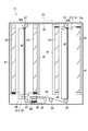
- FIG. 2 is a plan view showing the cover portion 12 c of the optical scanning device 12.
- FIG. 3 is a plan view for explaining the operation of the cleaning holder 51 provided in the cover portion 12c.
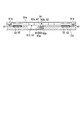
- FIG. 4 is a cross-sectional view showing a part of the cover portion 12c, and the cleaning holder 51 is viewed from the front.
- the housing 12a of the optical scanning device 12 includes the accommodating portion 12b and the cover portion 12c attached to the accommodating portion 12b.
- the cover portion 12c includes the four photosensitive drums 11a to 11d.
- four laser light emission ports are arranged in parallel.
- the shape of each emission port is a rectangular shape that is long in the main scanning direction of the corresponding laser beam, and each emission port is formed so that their longitudinal directions are parallel to each other.
- Each emission port is closed by a rectangular plate-shaped transparent member 52.
- the four permeable members 52 are arranged side by side so that their longitudinal directions are parallel to each other.
- Each of the transmissive members 52 is provided to prevent toner, dust, or the like from entering the optical scanning device 12.
- Each permeable member 52 is, for example, a glass cover.
- the optical scanning device 12 includes two cleaning holders 51, a first cleaning holder 511 and a second cleaning holder 512.
- Each cleaning holder 51 has a holding portion 51a (see FIG. 4).
- the holding part 51 a extends so as to straddle between two adjacent permeable members 52 and holds the two cleaning members 53.
- Each cleaning holder 51 is provided on the outer surface of the cover portion 12c (the surface on the photosensitive drums 11a to 11d side).
- Each cleaning member 53 is held by each holding portion 51 a so as to be arranged corresponding to each permeable member 52.
- Each cleaning member 53 is, for example, a rubber pad.
- silicon rubber can be used as the material of the rubber pad.
- Each cleaning holder 51 is formed of resin, for example.
- each cleaning member 53 is not limited to a rubber pad, For example, a nonwoven fabric may be sufficient.
- Each cleaning holder 51 is connected to a linear member 54 that is annularly stretched so as to pass between two adjacent permeable members 52.
- the linear member 54 travels in an annular shape by the driving force of the winding motor 55 that is a driving unit.
- the linear member 54 is, for example, a wire.
- the four cleaning members 53 slide on the outer surfaces (surfaces on the photosensitive drums 11a to 11d) of the four transmissive members 52 as the linear members 54 travel in an annular shape. Thereby, the outer surface of each permeable member 52 is simultaneously cleaned by the corresponding cleaning member 53.
- the take-up motor 55 can be rotated forward and backward. Thereby, it becomes possible to repeatedly perform the cleaning process of each permeable member 52.
- the winding motor 55 is, for example, a DC motor with a brush.
- the corresponding cleaning member 53 is reciprocated along the longitudinal direction of each permeable member 52 by rotating the winding motor 55 forward and backward in one cleaning process.
- the take-up motor 55 corresponds to an example of a “drive motor”. For example, every time printing (image formation) of about 1,000 sheets is performed, a cleaning process is periodically performed. Further, the cleaning process may be executed by a user operating an input device such as a touch panel when the state of the image forming apparatus 1 is in the maintenance mode.
- the two cleaning holders 511 and 512 are linearly opposite to each other along the longitudinal direction (main scanning direction of the laser beam) of each transmissive member 52 as the linear member 54 travels in an annular shape.
- a first stopper 56 a is provided at one end of the moving path of the first cleaning holder 511
- a second stopper 56 b is provided at one end of the moving path of the second cleaning holder 512.
- the first and second stoppers 56 a and 56 b are provided on one side in the longitudinal direction of each permeable member 52 between two adjacent permeable members 52.
- the travel of the linear member 54 stops.
- Resin can be used for the material of the 1st stopper 56a and the 2nd stopper 56b, for example.
- the first stopper 56a and the second stopper 56b are formed of resin, the first stopper 56a and the second stopper 56b may be integrally formed with the cover portion 12c.
- each cleaning holder 51 during one cleaning process will be described with reference to FIGS.
- the corresponding cleaning member 53 reciprocates once along the longitudinal direction of each permeable member 52 in one cleaning process.
- the traveling direction of the linear member 54 changes from the direction indicated by the arrow D1 (first direction) to the direction indicated by the arrow D2 (second direction) during the cleaning process.
- the winding motor 55 is controlled according to an instruction from the control unit 91 (see FIG. 1), and the “first operation”, “second operation”, and “third operation” are performed. It is done sequentially.
- the first operation first, the linear member 54 travels in the first direction indicated by the arrow D1 (see FIG. 2).
- the first and second cleaning holders 511 and 512 move from the position shown in FIG. 2 to the position shown in FIG. 3, and the first cleaning holder 511 contacts the first stopper 56a at one end of the moving path. Touch.
- the travel of the linear member 54 stops, and the first and second cleaning holders 511 and 512 stop.
- the load acting on the winding motor 55 increases.
- the winding motor 55 stops.
- the rotation direction of the winding motor 55 is reversed.
- the linear member 54 travels in the second direction (the direction opposite to the first direction) indicated by the arrow D2 (see FIG. 3). Then, the first and second cleaning holders 511 and 512 move from the position shown in FIG. 3 to the position shown in FIG. 2, and the second cleaning holder 512 abuts on the second stopper 56b at one end of the moving path. . As a result, the travel of the linear member 54 is stopped, and the operations of the first and second cleaning holders 511 and 512 are stopped. At this time, the load acting on the winding motor 55 increases. As the load increases, the rotation direction of the take-up motor 55 is reversed.
- the “third operation” is performed.
- the linear member 54 travels in the first direction indicated by the arrow D1 (see FIG. 3) for a predetermined time (for example, 75 msec).
- a predetermined time for example, 75 msec.
- the first and second cleaning holders 511 and 512 are moved to a preset standby position HP, and the winding motor 55 is stopped.
- the standby position HP is set at a position outside the image writing area of each transmissive member 52.
- first and second cleaning holders 511 and 512 are stopped at the standby position HP, damage received by the first and second stoppers 56a and 56b can be reduced. Further, since the first and second cleaning holders 511 and 512 are stopped at positions away from the first and second stoppers 56a and 56b, respectively, the start-up of the winding motor 55 can be facilitated.
- the two cleaning members 53 held by each cleaning holder 51 move in the same direction.
- one cleaning member 53 is held by one cleaning holder, as many cleaning holders as the number of the permeable members 52 are required. Therefore, a plurality of cleaning holders 51 are provided in one cleaning holder 51 as in this embodiment.
- the length of the linear member 54 for moving the cleaning holder becomes longer. Therefore, according to the present embodiment, the number of cleaning holders can be reduced, and the length of the necessary linear member 54 can be shortened, thereby reducing the cost.
- the four pulley pulleys 57 are rotatably held on the outer surface of the cover portion 12c.
- Four tension pulleys 57 are provided for tensioning the linear member 54 in a predetermined annular shape.
- a tension adjusting pulley 58 is rotatably held on the outer surface of the cover portion 12c.
- the linear member 54 is annularly stretched between the plurality of tension pulleys 57 and the tension adjustment pulley 58. Specifically, the linear member 54 is stretched between four adjacent permeable members 52 by four tension pulleys 57 so as to be parallel to the longitudinal direction of each permeable member 52.
- the tension adjusting pulley 58 is provided to adjust the tension applied to the linear member 54.
- the linear member 54 can smoothly run in an annular shape.
- the linear member 54 is wound around the winding drum 59 a number of times, and the linear motor 54 travels in an annular manner when the winding motor 55 rotates the winding drum 59.
- the winding motor 55 and the winding drum 59 are disposed in a recess 60 formed in the cover portion 12c.
- the take-up drum 59 is rotatably held by the cover portion 12 c in the recess 60.
- the winding motor 55 is fixed to the cover portion 12 c in the recess 60.
- the take-up motor 55 may be fixed to the housing portion 12b.
- each cleaning holder 51 is engaged with the cover portion 12 c so as to be movable along the longitudinal direction of each permeable member 52.
- an example of engagement between each cleaning holder 51 and the cover portion 12c will be described with reference to FIGS.
- each guide rail 61 extends along the longitudinal direction of each permeable member 52, and both end portions of each cleaning holder 51 (holding portion 51 a) engage with a corresponding pair of guide rails 61.
- Each cleaning holder 51 is guided along the longitudinal direction of each permeable member 52 by a corresponding pair of guide rails 61. Therefore, each cleaning holder 51 can be stably moved along the longitudinal direction of each permeable member 52.
- each guide rail 61 is provided with a locking portion 61a that protrudes toward the corresponding cleaning holder 51.
- Each locking portion 61 a extends along the longitudinal direction of each permeable member 52. Both end portions of the holding portion 51a of each cleaning holder 51 are locked to the locking portions 61a of the corresponding pair of guide rails 61 in the direction away from the housing 12a of the optical scanning device 12 (upward direction in FIG. 4). Thus, the upward movement (position shift) of each cleaning holder 51 is regulated.
- each locking portion 61a can prevent the cleaning holder 51 from being detached from the cover portion 12c, and can stably attach the corresponding cleaning member 53 to each permeable member 52.
- the locking portions 61a are provided so that both end portions of the holding portions 51a of the cleaning holders 51 are always in contact with the locking portions 61a of the corresponding pair of guide rails 61, respectively. Thereby, each cleaning member 53 can be pressed by the corresponding permeable member 52. Therefore, each cleaning member 53 can be more closely attached to the corresponding permeable member 52.
- each guide rib 62 projects from the outer surface of the cover portion 12c corresponding to each cleaning holder 51.
- Each guide rib 62 extends between two adjacent permeable members 52 along the longitudinal direction of each permeable member 52.
- an engaging portion 63 is provided on the lower end side of each cleaning holder 51, and each engaging portion 63 engages with a corresponding guide rib 62. Accordingly, the corresponding cleaning holder 51 is guided along the longitudinal direction of each permeable member 52 by each guide rib 62. Thereby, each cleaning holder 51 can be stably moved along the longitudinal direction of each permeable member 52.
- each guide rib 62 is disposed at a position closer to the linear member 54. Thereby, the swing of each cleaning holder 51 can be further suppressed during the cleaning process. That is, each cleaning holder 51 can be moved more stably along the longitudinal direction of each permeable member 52. More preferably, each guide rib 62 is provided directly below the linear member 54. Thereby, the rocking
- the linear member 54 is connected to the upper end portion side of the holding portion 51 a of each cleaning holder 51, and each engaging portion 63 is located on the lower end portion side of the corresponding holding portion 51 a of the cleaning holder 51. Is provided. Thereby, the engaging location of each guide rib 62 and each engaging part 63 can be provided directly under the connection location of the corresponding cleaning holder 51 and the linear member 54.
- each engaging portion 63 includes a pair of projecting portions 63 a that project downward from the corresponding cleaning holder 51, and each guide rib 62 has a corresponding pair of projecting portions. It is sandwiched between 63a. Thereby, the movement to the left-right direction of each cleaning holder 51 can be controlled. Further, the swing of each cleaning holder 51 around the axis extending in the vertical direction (the swing of each cleaning holder 51 in the moving direction) can be limited.
- each guide rib 62 has a protruding portion 62b protruding from the cover portion 12c and a locking portion 62a protruding from the tip of the protruding portion 62b.
- the locking part 62a extends in the left direction (one direction of the extending direction of the holding part 51a) from the tip part of the protruding part 62b.
- each cleaning holder 51 extends to the right (in the other direction of the extending direction of the holding part 51a) from one of the pair of protrusions 63a of the pair of engaging parts 63, and engages the guide rib 62. It has the latching
- each cleaning holder 51 may be deformed into a bow shape.
- each cleaning member 53 may be separated from the corresponding transparent member 52 on the center side of each cleaning holder 51.
- the cover portion 12c includes the locking portion 62a and each cleaning holder 51 includes the locking portion 63b. Therefore, when each cleaning holder 51 is deformed into an arcuate shape, the engagement of each guide rib 62 is increased.
- the locking portion 63b of the corresponding cleaning holder 51 is locked to the stop portion 62a in the direction away from the housing 12a of the optical scanning device 12, thereby suppressing the arcuate deformation of each cleaning holder 51.
- the corresponding cleaning member 53 can be stably adhered to each permeable member 52.
- the locking portion 63b of the corresponding cleaning holder 51 (engaging portion 63) is locked to the locking portion 62a of each guide rib 62 below the position where each permeable member 52 is disposed. Thereby, the effect which suppresses the bow-shaped deformation
- FIG. 5 is a plan view showing a state in which the cleaning holders 51 are respectively arranged on two cleaning holder attaching / detaching portions 64 (see FIG. 2) formed on the cover portion 12c. As shown in FIG. 2, the two cleaning holder attaching / detaching portions 64 are formed corresponding to the respective cleaning holders 51. Each cleaning holder attaching / detaching portion 64 is a recess here.
- FIG. 5 is a plan view showing a state in which the cleaning holders 51 are respectively arranged on two cleaning holder attaching / detaching portions 64 (see FIG. 2) formed on the cover portion 12c. As shown in FIG. 2, the two cleaning holder attaching / detaching portions 64 are formed corresponding to the respective cleaning holders 51. Each cleaning holder attaching / detaching portion 64 is a recess here.
- FIG. 6 is an enlarged perspective view showing a part of the cover portion 12 c, and shows a state in which the first cleaning holder 511 is disposed on the cleaning holder attaching / detaching portion 64.
- FIG. 7 is an enlarged perspective view showing a part of the cover portion 12 c, and shows a state in which the first cleaning holder 511 is engaged with the pair of guide rails 61 and guide ribs 62.
- each cleaning holder 51 is arranged in a corresponding cleaning holder attaching / detaching portion 64.
- the cleaning holder attaching / detaching portion 64 of the first cleaning holder 511 is provided outside the end of the moving path of the first cleaning holder 511 opposite to the side on which the first stopper 56a is disposed.
- the cleaning holder attaching / detaching portion 64 of the second cleaning holder 512 is provided outside the end opposite to the side where the second stopper 56b is disposed in the moving path of the second cleaning holder 512.
- both end portions of the holding portion 51 a of the first cleaning holder 511 are connected to the corresponding pair of guide rails 61. Not engaged.
- both end portions of the holding portion 51 a of the second cleaning holder 512 are engaged with the corresponding pair of guide rails 61. Absent.
- the guide rib 62 with which the first cleaning holder 511 is engaged is provided along the permeable member 52 from one end of the movement path of the first cleaning holder 511 to the corresponding cleaning holder attaching / detaching portion 64. ing. Therefore, the guide rib 62 with which the first cleaning holder 511 is engaged is also provided in the cleaning holder attaching / detaching portion 64.
- the locking portion 62 a of the guide rib 62 is provided along the permeable member 52 from one end to the other end of the moving path of the first cleaning holder 511, but is not provided in the cleaning holder attaching / detaching portion 64. Therefore, as shown in FIG.
- the first cleaning holder 511 is placed on the cleaning holder attaching / detaching portion 64 from above, and the engaging portion 63 of the first cleaning holder 511 is easily engaged with the guide rib 62. Can do.
- the second cleaning holder 512 can be placed on the cleaning holder attaching / detaching portion 64 from above, and the engaging portion 63 of the second cleaning holder 512 can be easily engaged with the guide rib 62.
- the pair of guide rails 61 is provided along the longitudinal direction of each permeable member 52 from one end to the other end of the moving path of each cleaning holder 51, and the direction in which each permeable member 52 is arranged in parallel (each It is not provided in a region where the region of the cleaning holder attaching / detaching portion 64 is extended in a direction perpendicular to the longitudinal direction of the permeable member 52. Therefore, as shown in FIG. 6, after the first cleaning holder 511 is disposed in the corresponding cleaning holder attaching / detaching portion 64, the first cleaning holder 511 is moved in the longitudinal direction of each permeable member 52 as shown in FIG. 7.
- FIGS. 8 is an enlarged perspective view showing a part of the cover portion 12c
- FIG. 9 is an enlarged plan view showing a part of the cleaning holder 51. As shown in FIG.
- a spherical connecting member 65 is fixed to the linear member 54 corresponding to each cleaning holder 51.
- the recessed part 81 is formed in the upper end part of the holding part 51a of each cleaning holder 51, and the spherical connection member 65 corresponding to each recessed part 81 is loosely fitted.
- each cleaning holder 51 is connected to the linear member 54.
- Each connecting member 65 may be fixed by being crimped to the linear member 54, for example.
- a resin can be used as the material of the connecting member 65.
- the linear member 54 such as a wire is employed as the means for moving the cleaning holder 51. Since the linear member 54 has a diameter smaller than that of the screw shaft used in the prior art, the optical scanning device 12 can be reduced in height.
- the first stopper 56a and the second stopper 56b are provided at one end of the moving path of the first and second cleaning holders 511 and 512, respectively.
- the first cleaning holder 511 moves to one end of the moving path and comes into contact with the first stopper 56a
- the second cleaning holder 512 is positioned at the other end of the moving path.
- the first cleaning holder 511 is positioned at the other end of the movement path.
- the stopper Since the stopper is not provided at the other end of each moving path of the first and second cleaning holders 511 and 512, the first and second cleaning holders 511 and 512 are connected to the first and second cleaning paths 51 in the moving path.
- the stopper does not get in the way, and the first and second cleaning holders 511 and 512 are easily assembled to the cover portion 12c. be able to. Therefore, the first and second cleaning holders 511 and 512 that are cleaning mechanisms can be easily assembled to the optical scanning device 12.
- a cleaning holder attaching / detaching portion 64 is provided on the outside of the end opposite to the side where the 56b is disposed. In this manner, the first and second cleaning holders 511 and 512 can be more easily assembled to the housing 12a of the optical scanning device 12 by forming the cleaning holder attaching / detaching portion 64 in the cover portion 12c.
- FIG. 10 is a diagram illustrating a functional configuration of the control unit 91 and the storage unit 92 illustrated in FIG. 1.
- the control unit 91 includes a CPU (Central Processing Unit), a ROM (Read Only Memory), and a RAM (Random Access Memory).
- a control program is stored in the ROM.
- the CPU functions as various functional units such as the start determination unit 911, the drive control unit 912, the contact determination unit 913, and the abnormality determination unit 914 by reading and executing the control program stored in the ROM. To do.
- the RAM is used as a work area when the CPU executes the control program.
- the storage unit 92 is, for example, a nonvolatile memory such as a flash memory, an EEPROM (Electrically Erasable Programmable Read-Only Memory), or an HDD (Hard Disk Drive), and stores various pieces of information.
- the CPU causes the storage unit 92 to function as the abnormal storage unit 921 by reading and executing the control program stored in the ROM.
- the abnormality storage unit 921 stores the abnormality content information indicating the content of the abnormality in association with the date and time information on the occurrence of the abnormality.
- the abnormality content information is information such as information indicating a situation where an abnormality has occurred and information indicating a reason for determining that an abnormality has occurred.
- the start determination unit 911 determines whether or not to start the cleaning process described above with reference to FIGS. Specifically, the start determination unit 911 receives an instruction that the image forming apparatus 1 performs printing, and the cleaning process is performed when the increased number N is equal to or greater than a predetermined threshold number NS (for example, 1,000). Is determined to start.
- the print instruction is, for example, a print instruction from a personal computer connected to the image forming apparatus 1 or a copy start instruction from an operation input unit arranged in the image forming apparatus 1.
- the increased number N is a difference obtained by subtracting the sheet count value obtained when the previous cleaning process was performed from the sheet count value when the image forming apparatus 1 received an instruction to print.
- the start determination unit 911 acquires the sheet count value from the sheet counter 93.
- the drive control unit 912 controls the drive of the winding motor 55 to perform the cleaning process. Specifically, the drive control unit 912 performs the first operation, the second operation, and the third operation described with reference to FIGS. 2 and 3 via the winding motor 55. In the first operation, first, the drive control unit 912 rotates the winding motor 55 in the forward direction to cause the linear member 54 to travel in the first direction D1 (see FIG. 2). Next, in the first operation, when the contact determination unit 913 determines that the first cleaning holder 511 has moved to one end of the movement path and has contacted the first stopper 56a, the drive control unit 912 performs the winding operation. The take-off motor 55 is switched to reverse rotation.
- the drive control unit 912 rotates the winding motor 55 in the reverse direction to cause the linear member 54 to travel in the second direction D2 (see FIG. 3).
- the drive control unit 912 performs the winding operation.
- the take-off motor 55 is switched to forward rotation.
- the drive control unit 912 rotates the winding motor 55 in the forward direction to cause the linear member 54 to travel in the first direction D1 and move the first cleaning holder 511 and the second cleaning holder 512 to the standby position HP. Then, the take-up motor 55 is stopped.
- the drive control unit 912 stops driving the winding motor 55 when the abnormality determination unit 914 determines that an abnormality has occurred.
- the contact determination unit 913 determines whether or not the cleaning holder has contacted the stopper based on the current value of the winding motor 55.
- “the cleaning holder is in contact with the stopper” means that the first cleaning holder 511 is in contact with the first stopper 56a or the second cleaning holder 512 is in contact with the second stopper 56b.
- the current value detected by an ammeter 551 disposed in the winding motor 55 is equal to or greater than a preset current value AS for a preset duration TA (eg, 100 msec) or more. In this case, it is determined that the cleaning holder has come into contact with the stopper.
- the current value AS is, for example, the continuous maximum current value (for example, twice the rated current value) of the winding motor 55 or the instantaneous maximum current value (for example, four times the rated current value).
- the abnormality determination unit 914 indicates that the cleaning holder has contacted the stopper by the contact determination unit 913 within a preset second threshold time TS2 from the time when the second operation is started by the drive control unit 912. When it is determined, it is determined that an abnormality has occurred. In addition, when it is determined that an abnormality has occurred, the abnormality determination unit 914 records the abnormality content information indicating the content of the abnormality in the abnormality storage unit 921 in association with the date and time information on the occurrence of the abnormality.
- the second threshold time TS2 is set to be equal to or less than a required time (for example, 800 msec) when the winding motor 55 performs the second operation with no load.
- the current value of the take-up motor 55 becomes equal to or greater than the current value AS within the second threshold time TS2, which is a time shorter than the time required when the take-up motor 55 performs the second operation with no load. ing. Therefore, for example, it can be determined as abnormal that a foreign object is caught between the guide rail 61 and the cleaning holder 51 shown in FIG.
- the abnormality determination unit 914 records the abnormality content information indicating the content of the abnormality in the abnormality storage unit 921 in association with the date and time information on the occurrence of the abnormality, so that the serviceman can perform maintenance on the image forming apparatus 1. When you do, you can know the occurrence of abnormality. Therefore, maintenance can be facilitated.
- the abnormality determination unit 914 determines that an abnormality has occurred when the elapsed time from the start of the second operation until it is determined to be in contact is less than a preset first threshold time TS1. Although the case will be described, the abnormality determination unit 914 may determine that an abnormality has occurred by another method.
- the abnormality determination unit 914 determines that the cleaning holder has contacted the stopper by the contact determination unit 913 within a preset first threshold time TS1 from the time when the first operation is started by the drive control unit 912. If it is determined that an abnormality has occurred.
- the first threshold time TS1 is set to be equal to or shorter than a required time (for example, 0.3 seconds) when the winding motor 55 performs the first operation in a no-load state.
- the current value of the take-up motor 55 is equal to or greater than the current value AS within the first threshold time TS1, which is a time shorter than the time required when the take-up motor 55 performs the first operation with no load. It has become. Therefore, for example, it can be determined as abnormal that a foreign object is caught between the guide rail 61 and the cleaning holder 51 shown in FIG.
- the abnormality determination unit 914 when the elapsed time from the start of the first operation is equal to or greater than a preset third threshold time TS3, the abnormality determination unit 914 generates an abnormality when the first operation has not ended.
- the form which determines with having carried out may be sufficient.
- the third threshold time TS3 is a time at which the first operation is reliably completed when the optical scanning device 12 is normal, and is, for example, 5 seconds.
- the abnormality determination unit 914 determines that an abnormality has occurred. For example, when the torque transmission path (gear etc.) which transmits the torque of the winding motor 55 to the linear member 54 is damaged, the torque of the winding motor 55 is not transmitted to the linear member 54, The linear member 54 does not travel. Therefore, the abnormality determination unit 914 determines that an abnormality has occurred.
- the abnormality determination unit 914 indicates that the conductive wire that supplies power to the take-up motor 55 is disconnected, or a torque transmission path (gear or the like) that transmits the torque of the take-up motor 55 to the linear member 54. ) Can be determined to be damaged.
- the abnormality determination unit 914 when the elapsed time from the start of the second operation is equal to or greater than a preset fourth threshold time TS4, the abnormality determination unit 914 generates an abnormality when the second operation has not ended.
- the form which determines with having carried out may be sufficient.
- the fourth threshold time TS4 is a time at which the second operation is reliably completed when the optical scanning device 12 is normal, and is, for example, 5 seconds.
- the abnormality determination unit 914 determines that an abnormality has occurred. For example, when the torque transmission path (gear etc.) which transmits the torque of the winding motor 55 to the linear member 54 is damaged, the torque of the winding motor 55 is not transmitted to the linear member 54, The linear member 54 does not travel. Therefore, the abnormality determination unit 914 determines that an abnormality has occurred.
- the abnormality determination unit 914 indicates that the conductive wire that supplies power to the take-up motor 55 is disconnected, or a torque transmission path (gear or the like) that transmits the torque of the take-up motor 55 to the linear member 54. ) Can be determined to be damaged.
- FIG. 11 is a flowchart (first half) showing the operation of the control unit 91 shown in FIG.
- FIG. 12 is a flowchart (second half) showing the operation of the control unit shown in FIG.
- the start determination unit 911 determines whether or not a print command has been accepted (step S101). If it is determined that the print command has been received (YES in step S101), the process proceeds to step S103. If it is determined that the print command has not been received (NO in step S101), the process is set to a standby state.
- step S101 the start determination unit 911 reads the sheet count value from the sheet counter 93 (step S103). Then, the start determination unit 911 determines whether or not the increased number N is greater than or equal to the threshold number NS (step S105). If it is determined that the increased number N is greater than or equal to the threshold number NS (YES in step S105), the process proceeds to step S107. If it is determined that the increased number N is not greater than or equal to the threshold number NS (NO in step S105), the process returns to step S101.
- step S105 in the case of NO in step S109, or in the case of NO in step S111, the drive control unit 912 rotates the winding motor 55 in the forward direction to move the linear member 54 in the first direction D1.
- An operation (hereinafter referred to as an outward movement) is performed (refer to FIG. 2) (step S107).
- step S109 determines whether or not the activation time ⁇ T (for example, 200 msec) has elapsed since the start of the forward movement operation (step S109). If it is determined that the activation time ⁇ T has elapsed since the start of the forward movement operation (YES in step S109), the process proceeds to step S111. If it is determined that the activation time ⁇ T has not elapsed since the start of the forward movement operation (NO in step S109), the process returns to step S107.
- the activation time ⁇ T for example, 200 msec
- step S109 whether or not the current value detected by the ammeter 551 is greater than or equal to the preset current value AS by the contact determination unit 913 for a duration TA (for example, 100 msec) or longer. Is determined (step S111). If it is determined that the current value detected by ammeter 551 is greater than or equal to current value AS for duration TA or longer (YES in step S111), the process proceeds to step S113. If it is determined that the current value detected by ammeter 551 is not greater than or equal to current value AS for duration TA or longer (NO in step S111), the process returns to step S107.
- a duration TA for example, 100 msec
- step S113 the winding controller 55 stops the winding motor 55 for a stop time TB (for example, 200 msec) (step S113). If step S113 is completed, if NO in step S117, or if NO in step S119, as shown in FIG. 12, the drive control unit 912 rotates the take-up motor 55 in the reverse direction to form a linear shape. An operation of causing the member 54 to travel in the second direction D2 (see FIG. 3) (hereinafter referred to as a return path operation) is performed (step S115).
- a return path operation An operation of causing the member 54 to travel in the second direction D2 (see FIG. 3) (hereinafter referred to as a return path operation) is performed (step S115).
- the drive control unit 912 determines whether or not the activation time ⁇ T (for example, 200 msec) has elapsed since the return path operation was started (step S117). If it is determined that the activation time ⁇ T has elapsed since the start of the return path operation (YES in step S117), the process proceeds to step S119. If it is determined that the activation time ⁇ T has not elapsed since the start of the return path operation (NO in step S117), the process returns to step S115.
- the activation time ⁇ T for example, 200 msec
- step S117 whether or not the current value detected by the ammeter 551 is greater than or equal to a preset current value AS by the contact determination unit 913 for a duration TA (eg, 100 msec) or longer. Is determined (step S119). If it is determined that the current value detected by the ammeter 551 is equal to or greater than the current value AS for the duration TA or longer, the process proceeds to step S121. If it is determined that the current value detected by ammeter 551 is not greater than or equal to current value AS for duration TA or longer (NO in step S119), the process returns to step S115.
- a preset current value AS eg, 100 msec
- the abnormality determination unit 914 determines whether or not a predetermined threshold time TC (for example, 800 msec) has elapsed since the start of the return path operation (step S121). If it is determined that the threshold time TC or more has elapsed since the start of the return path operation (YES in step S121), the process proceeds to step S123. If it is determined that the threshold time TC or more has not elapsed since the start of the return path operation (NO in step S121), the process proceeds to step S127.
- a predetermined threshold time TC for example, 800 msec
- step S121 the drive control unit 912 stops the winding motor 55 for a stop time TB (eg, 200 msec) (step S123). Then, the drive control unit 912 rotates the winding motor 55 in the forward direction so that the linear member 54 travels in the first direction D1 (see FIG. 2) and waits for the first cleaning holder 511 and the second cleaning holder 512. An operation of moving to the position HP is performed (step S125). Next, the drive control unit 912 stops the driving of the take-up motor 55 (step S127), and the process ends.
- a stop time TB eg, 200 msec
- step S121 If NO in step S121, the drive control unit 912 stops driving the winding motor 55 (step S129). Then, the abnormality determination unit 914 determines that an abnormality has occurred (step S131). Next, the abnormality determination unit 914 records abnormality content information indicating the content of the abnormality in the abnormality storage unit 921 in association with the date and time information on the occurrence of the abnormality (step S133), and the process is terminated.
- the contact determination unit 913 may determine that the current value detected by the ammeter 551 is equal to or greater than the preset current value AS for the duration TA or longer. Therefore, as described above, after the activation time ⁇ T has elapsed (step S109 and step S117), it is determined whether or not the cleaning holder has contacted the stopper (step S111 and step S119). The portion 913 can accurately determine whether or not the cleaning holder has come into contact with the stopper.
- the contact determination unit 913 may determine that the current value detected by the ammeter 551 is equal to or greater than the preset current value AS for the duration TA or longer. Therefore, as described above, by changing the rotation direction of the take-up motor 55 before stopping the take-up motor 55 for the stop time TB (step S113 and step S123), the contact determination unit 913 performs the following operation. It is possible to accurately determine whether or not the cleaning holder has come into contact with the stopper.
- the tension pulley 57 is used to tension the linear member 54 in an annular shape.
- the member that stretches the linear member 54 in an annular shape is not limited to a pulley.
- a plurality of protrusions may be provided on the outer surface of the cover portion 12c, and the linear member 54 may be bridged over each protrusion.
- at least one protrusion may be provided on the outer surface of the cover portion 12c as the tension adjusting mechanism.
- one tension adjusting pulley 58 is provided, but the number of tension adjusting pulleys 58 is not particularly limited.
- the tension adjusting pulley 58 is provided as a tension adjusting mechanism for adjusting the tension applied to the linear member 54.
- the tension adjusting mechanism may be omitted.
- the winding drum 59 is provided, but the winding drum 59 may be omitted.
- the recording medium is a sheet
- the recording medium may be other than the sheet (for example, a resin sheet or a fabric).
- tandem type color printer is exemplified, but the present invention is not limited to this, and can be applied to an electrophotographic image forming apparatus such as a color copying machine or a facsimile.
- the optical scanning device 12 is disposed below the photosensitive drums 11a to 11d.
- the optical scanning device 12 may be disposed above the photosensitive drums 11a to 11d.
- the winding motor 55 is a brushed DC motor
- the winding motor 55 may be another type of motor.
- the winding motor 55 may be a brushless DC motor.
- the winding motor 55 may be an AC motor.
- the present invention is applicable to an image forming apparatus including an optical scanning device that forms an electrostatic latent image by irradiating light onto an image carrier.
Landscapes
- Physics & Mathematics (AREA)
- General Physics & Mathematics (AREA)
- Engineering & Computer Science (AREA)
- Multimedia (AREA)
- Signal Processing (AREA)
- Optics & Photonics (AREA)
- Health & Medical Sciences (AREA)
- General Health & Medical Sciences (AREA)
- Toxicology (AREA)
- Exposure Or Original Feeding In Electrophotography (AREA)
- Laser Beam Printer (AREA)
- Mechanical Optical Scanning Systems (AREA)
Abstract
Description
Claims (10)
- 複数の像担持体にレーザー光を照射して静電潜像を形成する光走査装置を備える画像形成装置であって、
前記複数の像担持体に対応して、前記レーザー光の主走査方向に延びる複数のレーザー光の出射口が並設された筐体と、
前記レーザー光に対する透過性を有し、前記レーザー光の主走査方向に延び、且つ、前記複数のレーザー光の出射口をそれぞれ閉塞する複数の透過性部材と、
前記複数の透過性部材のそれぞれに対応して配置され、対応する前記透過性部材に摺動されることにより当該透過性部材を清掃する複数の清掃部材と、
前記筐体に環状に張設された線状部材と、
前記線状部材を第1方向、及び、前記第1方向とは相違する第2方向に環状走行させる駆動モーターと、
それぞれが前記清掃部材を少なくとも2つ保持し、前記駆動モーターにより前記線状部材が環状走行されたときに前記透過性部材の延在方向に移動する、第1清掃ホルダー及び第2清掃ホルダーと、
前記第1清掃ホルダーの移動経路の一端に配設され、前記第1清掃ホルダーが当接することにより、前記第1清掃ホルダーの前記透過性部材の延在方向の一方向への移動を規制する第1ストッパーと、
前記第2清掃ホルダーの移動経路の一端に配設され、前記第2清掃ホルダーが当接することにより、前記第2清掃ホルダーの前記透過性部材の延在方向の一方向への移動を規制する第2ストッパーと、
前記第1清掃ホルダーが前記第1ストッパーに当接したこと、及び、前記第2清掃ホルダーが前記第2ストッパーに当接したことを、前記駆動モーターの電流値に基づいて判定する当接判定部と
を備える、画像形成装置。 - 前記駆動モーターは、直流モーターであって、
前記当接判定部は、前記駆動モーターの電流値が、予め設定された電流値以上である場合に、前記第1清掃ホルダーが前記第1ストッパーに当接した、又は、前記第2清掃ホルダーが前記第2ストッパーに当接したと判定する、請求項1に記載の画像形成装置。 - 前記駆動モーターを制御する駆動制御部を更に備え、
前記駆動制御部は、
前記駆動モーターを介して、前記線状部材を前記第1方向に環状走行させ、前記第1清掃ホルダーを前記透過性部材の延在方向の一方向に移動させると共に、前記第2清掃ホルダーを前記透過性部材の延在方向の他方向に移動させ、前記第1清掃ホルダーが前記移動経路の一端に移動して前記第1ストッパーに当接したときに、前記線状部材の走行方向を第2方向に切り替える第1動作を行わせると共に、
前記駆動モーターを介して、前記線状部材を前記第2方向に環状走行させ、前記第1清掃ホルダーを前記透過性部材の延在方向の他方向に移動させると共に、前記第2清掃ホルダーを前記透過性部材の延在方向の一方向に移動させ、前記第2清掃ホルダーが前記移動経路の一端に移動して前記第2ストッパーに当接したときに、前記駆動モーターを介して、前記線状部材の走行を停止させる第2動作を行わせる、請求項1に記載の画像形成装置。 - 異常の発生を判定する異常判定部を更に備え、
前記異常判定部は、前記駆動制御部によって前記第1動作が開始された時点から予め設定された第1閾値時間内に、前記当接判定部によって前記第1清掃ホルダーが前記第1ストッパーに当接したと判定された場合に、異常が発生したと判定する、請求項3に記載の画像形成装置。 - 前記異常判定部は、前記駆動制御部によって前記第2動作が開始された時点から予め設定された第2閾値時間内に、前記当接判定部によって、前記第2清掃ホルダーが前記第2ストッパーに当接したと判定された場合に、異常が発生したと判定する、請求項4に記載の画像形成装置。
- 前記第1閾値時間及び前記第2閾値時間は、それぞれ、前記駆動モーターが無負荷状態で前記第1動作及び前記第2動作を行う場合の所要時間以下に設定される、請求項5に記載の画像形成装置。
- 前記異常判定部は、前記第1動作の開始からの経過時間が予め設定された第3閾値時間以上となったときに、前記第1動作を終了していない場合に、異常が発生したと判定する、請求項4に記載の画像形成装置。
- 前記異常判定部は、前記第2動作の開始からの経過時間が予め設定された第4閾値時間以上となったときに、前記第2動作を終了していない場合に、異常が発生したと判定する、請求項4に記載の画像形成装置。
- 前記駆動制御部は、前記駆動モーターを介して、前記第1動作及び前記第2動作を行わせた後、予め設定された復帰時間の間、前記線状部材を前記第1方向に環状走行させ、前記第1清掃ホルダーを前記透過性部材の延在方向の一方向に移動させると共に、前記第2清掃ホルダーを前記透過性部材の延在方向の他方向に移動させる第3動作を行わせ、前記第1清掃ホルダー及び前記第2清掃ホルダーを、予め設定された待機位置に移動させる、請求項3に記載の画像形成装置。
- 前記駆動モーターは、直流モーターであって、
前記当接判定部は、前記駆動モーターの電流値が、予め設定された継続時間以上の間、予め設定された電流値以上である場合に、前記第1清掃ホルダーが前記第1ストッパーに当接した、又は、前記第2清掃ホルダーが前記第2ストッパーに当接したと判定する、請求項1に記載の画像形成装置。
Priority Applications (2)
| Application Number | Priority Date | Filing Date | Title |
|---|---|---|---|
| JP2016568300A JP6365689B2 (ja) | 2015-01-07 | 2015-12-14 | 画像形成装置 |
| US15/529,733 US10048641B2 (en) | 2015-01-07 | 2015-12-14 | Image forming apparatus |
Applications Claiming Priority (2)
| Application Number | Priority Date | Filing Date | Title |
|---|---|---|---|
| JP2015-001675 | 2015-01-07 | ||
| JP2015001675 | 2015-01-07 |
Publications (1)
| Publication Number | Publication Date |
|---|---|
| WO2016111118A1 true WO2016111118A1 (ja) | 2016-07-14 |
Family
ID=56355820
Family Applications (1)
| Application Number | Title | Priority Date | Filing Date |
|---|---|---|---|
| PCT/JP2015/084940 Ceased WO2016111118A1 (ja) | 2015-01-07 | 2015-12-14 | 画像形成装置 |
Country Status (3)
| Country | Link |
|---|---|
| US (1) | US10048641B2 (ja) |
| JP (1) | JP6365689B2 (ja) |
| WO (1) | WO2016111118A1 (ja) |
Cited By (3)
| Publication number | Priority date | Publication date | Assignee | Title |
|---|---|---|---|---|
| WO2019198757A1 (ja) * | 2018-04-11 | 2019-10-17 | キヤノン株式会社 | 画像形成装置 |
| JP2020091371A (ja) * | 2018-12-04 | 2020-06-11 | キヤノン株式会社 | 画像形成装置 |
| JP2021014037A (ja) * | 2019-07-10 | 2021-02-12 | 京セラドキュメントソリューションズ株式会社 | 光走査装置およびそれを備えた画像形成装置 |
Families Citing this family (2)
| Publication number | Priority date | Publication date | Assignee | Title |
|---|---|---|---|---|
| US11249413B2 (en) * | 2019-07-10 | 2022-02-15 | Kyocera Document Solutions Inc. | Optical scanning device and image forming apparatus including the same |
| JP2025131125A (ja) * | 2024-02-28 | 2025-09-09 | 京セラドキュメントソリューションズ株式会社 | 清掃装置及び画像形成装置 |
Citations (7)
| Publication number | Priority date | Publication date | Assignee | Title |
|---|---|---|---|---|
| JPH026972A (ja) * | 1988-06-24 | 1990-01-11 | Mita Ind Co Ltd | ワイヤ清掃装置 |
| JPH02118587A (ja) * | 1988-10-27 | 1990-05-02 | Niigata Nippon Denki Kk | 電子写真式プリンタ |
| JPH07239604A (ja) * | 1994-02-25 | 1995-09-12 | Nec Corp | 電子写真式記録装置 |
| JP2002361927A (ja) * | 2001-06-12 | 2002-12-18 | Canon Inc | 画像形成装置 |
| JP2008134305A (ja) * | 2006-11-27 | 2008-06-12 | Konica Minolta Business Technologies Inc | 画像形成装置及び放電電極清掃装置 |
| JP2009122501A (ja) * | 2007-11-16 | 2009-06-04 | Murata Mach Ltd | 画像形成装置 |
| JP2009139816A (ja) * | 2007-12-10 | 2009-06-25 | Kyocera Mita Corp | 画像形成装置 |
Family Cites Families (1)
| Publication number | Priority date | Publication date | Assignee | Title |
|---|---|---|---|---|
| JP5144823B2 (ja) * | 2012-04-25 | 2013-02-13 | 京セラドキュメントソリューションズ株式会社 | 光学ユニットの自動清掃装置とこれを備えた光学ユニット及び画像形成装置 |
-
2015
- 2015-12-14 US US15/529,733 patent/US10048641B2/en active Active
- 2015-12-14 WO PCT/JP2015/084940 patent/WO2016111118A1/ja not_active Ceased
- 2015-12-14 JP JP2016568300A patent/JP6365689B2/ja active Active
Patent Citations (7)
| Publication number | Priority date | Publication date | Assignee | Title |
|---|---|---|---|---|
| JPH026972A (ja) * | 1988-06-24 | 1990-01-11 | Mita Ind Co Ltd | ワイヤ清掃装置 |
| JPH02118587A (ja) * | 1988-10-27 | 1990-05-02 | Niigata Nippon Denki Kk | 電子写真式プリンタ |
| JPH07239604A (ja) * | 1994-02-25 | 1995-09-12 | Nec Corp | 電子写真式記録装置 |
| JP2002361927A (ja) * | 2001-06-12 | 2002-12-18 | Canon Inc | 画像形成装置 |
| JP2008134305A (ja) * | 2006-11-27 | 2008-06-12 | Konica Minolta Business Technologies Inc | 画像形成装置及び放電電極清掃装置 |
| JP2009122501A (ja) * | 2007-11-16 | 2009-06-04 | Murata Mach Ltd | 画像形成装置 |
| JP2009139816A (ja) * | 2007-12-10 | 2009-06-25 | Kyocera Mita Corp | 画像形成装置 |
Cited By (4)
| Publication number | Priority date | Publication date | Assignee | Title |
|---|---|---|---|---|
| WO2019198757A1 (ja) * | 2018-04-11 | 2019-10-17 | キヤノン株式会社 | 画像形成装置 |
| JP2020091371A (ja) * | 2018-12-04 | 2020-06-11 | キヤノン株式会社 | 画像形成装置 |
| JP2021014037A (ja) * | 2019-07-10 | 2021-02-12 | 京セラドキュメントソリューションズ株式会社 | 光走査装置およびそれを備えた画像形成装置 |
| JP7310384B2 (ja) | 2019-07-10 | 2023-07-19 | 京セラドキュメントソリューションズ株式会社 | 光走査装置およびそれを備えた画像形成装置 |
Also Published As
| Publication number | Publication date |
|---|---|
| US10048641B2 (en) | 2018-08-14 |
| JPWO2016111118A1 (ja) | 2017-09-07 |
| JP6365689B2 (ja) | 2018-08-01 |
| US20170329275A1 (en) | 2017-11-16 |
Similar Documents
| Publication | Publication Date | Title |
|---|---|---|
| JP6264222B2 (ja) | 光走査装置、及びこれを備えた画像形成装置 | |
| JP6256241B2 (ja) | 光走査装置、及びこれを備えた画像形成装置 | |
| JP6365689B2 (ja) | 画像形成装置 | |
| US8406665B2 (en) | Belt driving device and image forming apparatus using the same | |
| US10191445B2 (en) | Image forming apparatus | |
| US9213272B2 (en) | Image forming apparatus including a holding member to hold a roller relative to a frame | |
| US12259665B2 (en) | Optical scanning device and image forming apparatus including the same | |
| JP2020101591A (ja) | 画像形成装置及び画像形成装置のプロセスユニット交換方法 | |
| US20140233987A1 (en) | Image forming apparatus | |
| US20200033749A1 (en) | Image forming apparatus | |
| JP7810270B2 (ja) | 光走査装置およびそれを備えた画像形成装置 | |
| US11249413B2 (en) | Optical scanning device and image forming apparatus including the same | |
| JP7310384B2 (ja) | 光走査装置およびそれを備えた画像形成装置 | |
| JP2015225237A (ja) | 光走査装置、及びこれを備えた画像形成装置 | |
| JP7310383B2 (ja) | 光走査装置およびそれを備えた画像形成装置 | |
| JP2021140175A (ja) | 画像形成装置 | |
| JP2020129082A (ja) | 画像形成装置 | |
| JP5920648B2 (ja) | 駆動装置並びにこれを用いたベルト蛇行修正装置及び画像形成装置 | |
| JP2019090965A (ja) | 照明装置、画像形成装置、画像読取装置 | |
| JP2008134305A (ja) | 画像形成装置及び放電電極清掃装置 |
Legal Events
| Date | Code | Title | Description |
|---|---|---|---|
| 121 | Ep: the epo has been informed by wipo that ep was designated in this application |
Ref document number: 15876991 Country of ref document: EP Kind code of ref document: A1 |
|
| ENP | Entry into the national phase |
Ref document number: 2016568300 Country of ref document: JP Kind code of ref document: A |
|
| WWE | Wipo information: entry into national phase |
Ref document number: 15529733 Country of ref document: US |
|
| NENP | Non-entry into the national phase |
Ref country code: DE |
|
| 122 | Ep: pct application non-entry in european phase |
Ref document number: 15876991 Country of ref document: EP Kind code of ref document: A1 |