WO2016111055A1 - 超音波プローブ - Google Patents
超音波プローブ Download PDFInfo
- Publication number
- WO2016111055A1 WO2016111055A1 PCT/JP2015/076188 JP2015076188W WO2016111055A1 WO 2016111055 A1 WO2016111055 A1 WO 2016111055A1 JP 2015076188 W JP2015076188 W JP 2015076188W WO 2016111055 A1 WO2016111055 A1 WO 2016111055A1
- Authority
- WO
- WIPO (PCT)
- Prior art keywords
- curved
- longitudinal axis
- vibration
- extending
- ultrasonic probe
- Prior art date
Links
Images


Classifications
-
- A—HUMAN NECESSITIES
- A61—MEDICAL OR VETERINARY SCIENCE; HYGIENE
- A61B—DIAGNOSIS; SURGERY; IDENTIFICATION
- A61B17/00—Surgical instruments, devices or methods, e.g. tourniquets
- A61B17/16—Bone cutting, breaking or removal means other than saws, e.g. Osteoclasts; Drills or chisels for bones; Trepans
- A61B17/1662—Bone cutting, breaking or removal means other than saws, e.g. Osteoclasts; Drills or chisels for bones; Trepans for particular parts of the body
- A61B17/1684—Bone cutting, breaking or removal means other than saws, e.g. Osteoclasts; Drills or chisels for bones; Trepans for particular parts of the body for the shoulder
-
- A—HUMAN NECESSITIES
- A61—MEDICAL OR VETERINARY SCIENCE; HYGIENE
- A61B—DIAGNOSIS; SURGERY; IDENTIFICATION
- A61B17/00—Surgical instruments, devices or methods, e.g. tourniquets
- A61B17/16—Bone cutting, breaking or removal means other than saws, e.g. Osteoclasts; Drills or chisels for bones; Trepans
- A61B17/1659—Surgical rasps, files, planes, or scrapers
-
- A—HUMAN NECESSITIES
- A61—MEDICAL OR VETERINARY SCIENCE; HYGIENE
- A61B—DIAGNOSIS; SURGERY; IDENTIFICATION
- A61B17/00—Surgical instruments, devices or methods, e.g. tourniquets
- A61B17/32—Surgical cutting instruments
- A61B17/320016—Endoscopic cutting instruments, e.g. arthroscopes, resectoscopes
- A61B17/32002—Endoscopic cutting instruments, e.g. arthroscopes, resectoscopes with continuously rotating, oscillating or reciprocating cutting instruments
-
- A—HUMAN NECESSITIES
- A61—MEDICAL OR VETERINARY SCIENCE; HYGIENE
- A61B—DIAGNOSIS; SURGERY; IDENTIFICATION
- A61B18/00—Surgical instruments, devices or methods for transferring non-mechanical forms of energy to or from the body
-
- A—HUMAN NECESSITIES
- A61—MEDICAL OR VETERINARY SCIENCE; HYGIENE
- A61B—DIAGNOSIS; SURGERY; IDENTIFICATION
- A61B17/00—Surgical instruments, devices or methods, e.g. tourniquets
- A61B17/32—Surgical cutting instruments
- A61B2017/320004—Surgical cutting instruments abrasive
-
- A—HUMAN NECESSITIES
- A61—MEDICAL OR VETERINARY SCIENCE; HYGIENE
- A61B—DIAGNOSIS; SURGERY; IDENTIFICATION
- A61B17/00—Surgical instruments, devices or methods, e.g. tourniquets
- A61B17/32—Surgical cutting instruments
- A61B2017/320004—Surgical cutting instruments abrasive
- A61B2017/320008—Scrapers
-
- A—HUMAN NECESSITIES
- A61—MEDICAL OR VETERINARY SCIENCE; HYGIENE
- A61B—DIAGNOSIS; SURGERY; IDENTIFICATION
- A61B17/00—Surgical instruments, devices or methods, e.g. tourniquets
- A61B17/32—Surgical cutting instruments
- A61B2017/320052—Guides for cutting instruments
-
- A—HUMAN NECESSITIES
- A61—MEDICAL OR VETERINARY SCIENCE; HYGIENE
- A61B—DIAGNOSIS; SURGERY; IDENTIFICATION
- A61B17/00—Surgical instruments, devices or methods, e.g. tourniquets
- A61B17/32—Surgical cutting instruments
- A61B17/320068—Surgical cutting instruments using mechanical vibrations, e.g. ultrasonic
- A61B2017/320072—Working tips with special features, e.g. extending parts
- A61B2017/320073—Working tips with special features, e.g. extending parts probe
-
- A—HUMAN NECESSITIES
- A61—MEDICAL OR VETERINARY SCIENCE; HYGIENE
- A61B—DIAGNOSIS; SURGERY; IDENTIFICATION
- A61B17/00—Surgical instruments, devices or methods, e.g. tourniquets
- A61B17/32—Surgical cutting instruments
- A61B17/320068—Surgical cutting instruments using mechanical vibrations, e.g. ultrasonic
- A61B2017/320072—Working tips with special features, e.g. extending parts
- A61B2017/320078—Tissue manipulating surface
-
- A—HUMAN NECESSITIES
- A61—MEDICAL OR VETERINARY SCIENCE; HYGIENE
- A61B—DIAGNOSIS; SURGERY; IDENTIFICATION
- A61B17/00—Surgical instruments, devices or methods, e.g. tourniquets
- A61B17/32—Surgical cutting instruments
- A61B17/320068—Surgical cutting instruments using mechanical vibrations, e.g. ultrasonic
- A61B2017/320089—Surgical cutting instruments using mechanical vibrations, e.g. ultrasonic node location
-
- A—HUMAN NECESSITIES
- A61—MEDICAL OR VETERINARY SCIENCE; HYGIENE
- A61N—ELECTROTHERAPY; MAGNETOTHERAPY; RADIATION THERAPY; ULTRASOUND THERAPY
- A61N7/00—Ultrasound therapy
- A61N2007/0043—Ultrasound therapy intra-cavitary
Definitions
- the present invention relates to an ultrasonic probe for cutting, for example, bone tissue and cartilage tissue by ultrasonic vibration.
- Patent Document 1 discloses an ultrasonic treatment apparatus including an ultrasonic probe (ultrasonic horn).
- ultrasonic vibration generated by the vibration generating unit (ultrasonic vibration mechanism) is transmitted from the proximal end side to the distal end side in the ultrasonic probe.
- a knife portion is formed as a treatment surface at the tip of the ultrasonic probe.
- the outer surface of the ultrasonic probe is formed in an uneven shape.
- ultrasonic treatment is transmitted to the knife portion, thereby cutting the treatment target (for example, bone or other hard tissue).
- a hard tissue such as a bone may be cut in a narrow space such as a joint cavity under observation with an endoscope (rigid endoscope).
- an endoscope rigid endoscope
- it is required to appropriately contact the treatment surface (cutting surface) of the ultrasonic probe with the bone even in a narrow space such as a joint cavity.
- a hard tissue such as a bone with an appropriate strength.
- the present invention has been made to solve the above-described problems, and an object of the present invention is to provide an ultrasonic probe in which a cutting surface is easily brought into contact with a hard tissue even in a narrow space and the hard tissue is appropriately cut. There is to do.
- an ultrasonic probe for the shoulder joint that transmits the ultrasonic vibration is extended along a longitudinal axis.
- a probe main body for transmitting the ultrasonic vibration from the proximal end side to the distal end side, and a first direction that is provided on the distal end side with respect to the probe main body portion and intersects the longitudinal axis In this case, a curved extending portion extending in a state of bending toward the first intersecting direction with respect to the probe main body, and a first facing the first intersecting direction side in the curved extending portion.
- a third curved outer surface facing the first width direction side in the curved extending portion when the two directions perpendicular to the direction are defined as a first width direction and a second width direction, and the curved extending portion
- a second curved outer surface facing the second width direction side, and a plurality of grooves on the second curved outer surface, and a treatment target is cut, and the first width direction and the second width
- the first cutting surface formed in an arc shape centered on the first intersecting direction side from the curved extending portion and the third curved outer surface are formed.
- the second cutting surface including a first extending groove that cuts the treatment target and extends along the thickness direction of the curved extending portion, and the fourth curved outer surface.
- the treatment target is cut and formed along the thickness direction of the curved extending portion.
- a third cutting surface having two extending grooves, and extending to the first cutting surface, one end continuous with the first extending groove, and the other end continuous with the second extending groove.
- a relay groove is
- an ultrasonic probe in which a cutting surface is easily brought into contact with a hard tissue even in a narrow space and the hard tissue is appropriately cut.
- FIG. 6 is a sectional view taken along line VI-VI in FIG. 5.
- FIG. 1 is a diagram showing an ultrasonic treatment system 1 of the present embodiment.
- the ultrasonic treatment system 1 includes an ultrasonic treatment instrument (handpiece) 2, an energy control device 3, and a transducer unit 5.
- the ultrasonic treatment instrument 2 has a longitudinal axis C.
- a direction parallel to the longitudinal axis C is defined as a longitudinal axis direction.
- One side in the longitudinal axis direction is the tip side (arrow C1 side in FIG. 1), and the side opposite to the tip side is the base side (arrow C2 side in FIG. 1).
- the ultrasonic treatment instrument 2 includes a holding unit 6, a sheath 7, and an ultrasonic probe 8.
- the holding unit 6 includes a holding casing 11 held by an operator and an energy operation button 12 which is attached to the holding casing 11 and is an energy operation input unit for an operator to operate.
- An ultrasonic probe (vibration transmission member) 8 is inserted into the sheath 7. Note that the distal end portion of the ultrasonic probe 8 protrudes from the distal end of the sheath 7 toward the distal end side.
- the vibrator unit 5 having the vibrator case 13 is connected to the proximal end side of the holding unit 6.
- One end of a cable 15 is connected to the vibrator unit 5.
- the other end of the cable 15 is connected to the energy control device 3.
- the energy control device 3 includes a power source, a conversion circuit that converts power from the power source into vibration-generated power, a processor (control unit) including a CPU (Central Processing Unit) or an ASIC (application specific integrated circuit), a memory, and the like.
- a storage medium Inside the holding casing 11, a switch (not shown) whose opening / closing state is changed by an input of an energy operation with the energy operation button 12 is provided.
- the switch is electrically connected to the processor of the energy control device 3 through a signal path extending through the vibrator unit 5 and the cable 15.
- the vibrating body unit 20 extends through the inside of the holding casing 11 and the inside of the vibrator case 13.
- FIG. 2 is a diagram showing the configuration of the vibrating body unit 20.
- the vibrating body unit 20 includes the above-described ultrasonic probe 8, an ultrasonic transducer 21 including a plurality of piezoelectric elements that are vibration generating units, and a relay transmission member 22.
- the ultrasonic transducer 21 and the relay transmission member 22 are disposed inside the transducer case 13, and the relay transmission member 22 is supported by the transducer case 13.
- the ultrasonic transducer 21 is attached to the relay transmission member 22.
- the ultrasonic probe 8 is connected to the distal end side of the relay transmission member 22 inside the holding casing 11.
- the relay transmission member 22 is provided with a cross-sectional area changing portion 23 in which a cross-sectional area perpendicular to the longitudinal axis C decreases toward the tip side.
- the cross-sectional area changing part (horn part) 23 is located on the tip side from the ultrasonic transducer 21.
- One end of the electrical wirings 25A and 25B is connected to the ultrasonic transducer 21.
- the electrical wirings 25 ⁇ / b> A and 25 ⁇ / b> B are extended through the inside of the cable 15 and the other ends are connected to the energy control device 3.
- the control unit controls the conversion circuit, and generates vibration generation power (vibration generation current) through the electric wires 25 ⁇ / b> A and 25 ⁇ / b> B.
- the ultrasonic transducer 21 is supplied. Thereby, ultrasonic vibration is generated in the ultrasonic transducer 21, and the generated ultrasonic vibration is transmitted to the ultrasonic probe 8 via the relay transmission member 22. At this time, the amplitude of the ultrasonic vibration is enlarged at the cross-sectional area changing portion 23 of the relay transmission member 22.
- the ultrasonic probe 8 includes a probe main body 31 that extends along the longitudinal axis C.
- the probe main body 31 extends substantially straight with the longitudinal axis C as the axis center.
- An engagement connecting portion 32 is provided on the proximal end side of the probe main body portion 31.
- an engagement groove (not shown) provided in the relay transmission member 22 (for example, by screwing a female screw and a male screw)
- a probe is connected to the distal end side of the relay transmission member 22.
- the main body 31 is connected.
- the contact surface 33 formed at the proximal end of the probe main body 31 contacts the relay transmission member 22. Ultrasonic vibration is transmitted from the relay transmission member 22 to the probe main body 31 through the contact surface 33.
- the ultrasonic vibration When the ultrasonic vibration is transmitted to the probe main body 31, the ultrasonic vibration is transmitted from the proximal end side to the distal end side in the probe main body portion 31 (ultrasonic probe 8).
- the vibrating body unit 20 performs longitudinal vibration in which the vibration direction is parallel to the longitudinal axis direction in a specified frequency range including a specified frequency.
- a vibration antinode (most proximal vibration antinode) A1 which is one of the vibration antinodes of the longitudinal vibration is located at the base end of the vibration body unit 20 (base end of the relay transmission member 22).
- a vibration antinode (most advanced vibration antinode) A2 which is one of the vibration antinodes of longitudinal vibration, is located at the tip (tip of the ultrasonic probe 8).
- the vibration antinode A1 is located on the most proximal side among the vibration antinodes of the longitudinal vibration
- the vibration antinode A2 is located on the most distal side among the vibration antinodes of the vertical vibration.
- the vibrating body unit 20 is designed to perform longitudinal vibration at 47 kHz (specified frequency) by transmitting ultrasonic vibration, and actually, a frequency range of 46 kHz to 48 kHz (specified frequency). Range).
- the ultrasonic probe 8 has a total length L1 from the distal end to the proximal end (the proximal end of the engagement connecting portion 32) in the longitudinal axis direction. In one embodiment, the total length L1 is 183.4 mm.
- the ultrasonic probe 8 has a longitudinal dimension L2 from the distal end to the contact surface 33 (the base end of the probe main body 31) in the longitudinal axis direction. In one embodiment, the longitudinal dimension L2 is preferably 177.5 mm.
- the probe main body portion 31 is provided with a horn portion (first horn portion) 35.
- the cross-sectional area perpendicular to the longitudinal axis C decreases toward the tip side.
- the horn part (cross-sectional area reduction part) 35 is located on the distal end side with respect to the contact surface 33, and the probe main body part 31 extends from the contact surface 33 to the base end (vibration input end) E1 of the horn part 35 in the longitudinal axis direction. It has a longitudinal dimension L3.
- the longitudinal dimension L3 is preferably 29 mm.
- the horn part (first horn part) 35 has a horn longitudinal dimension (first horn longitudinal dimension) L4 from the base end (vibration input end) E1 to the tip end (vibration output end) E2 in the longitudinal axis direction.
- the horn longitudinal dimension L4 is preferably 20 mm.
- the outer diameter of the probe main body portion 31 is kept substantially constant from the contact surface 33 to the proximal end E1 of the horn portion 35 in the longitudinal axis direction. Therefore, the probe main body portion 31 has an outer diameter D1 at the contact surface 33 and the proximal end E1 of the horn portion 35. In an embodiment, the outer diameter D1 is preferably 7 mm. Further, since the horn portion 35 has a cross-sectional area that decreases toward the distal end side, the probe main body portion 31 has an outer diameter D2 smaller than the outer diameter D1 at the distal end E2 of the horn portion 35. That is, in the horn part 35, the outer diameter of the probe main body part 31 decreases from the outer diameter D1 to the outer diameter D2 toward the distal end side. In an embodiment, the outer diameter D2 is preferably 3.8 mm.
- the vibration node N1 which is one of the vibration nodes of the longitudinal vibration is the proximal end E1 of the horn portion 35 or the vicinity of the proximal end E1.
- the vibration antinodes of the longitudinal vibration are located away from the horn portion 35 in the longitudinal axis direction. For this reason, in the horn part 35 whose cross-sectional area decreases toward the tip side, the amplitude of longitudinal vibration (ultrasonic vibration) is expanded.
- longitudinal vibration having an amplitude of 18 ⁇ m at the vibration antinode is transmitted to the base end E1 of the horn part 35, and the amplitude of the longitudinal vibration is expanded by the horn part 35.
- the vibration node N1 is located at the proximal end E1 of the horn portion 35 in a state where the vibrating body unit 20 vibrates longitudinally at a specified frequency (eg, 47 kHz) included in the specified frequency range.
- the probe main body portion 31 is provided with a horn portion (second horn portion) 36.
- the cross-sectional area perpendicular to the longitudinal axis C decreases toward the tip side.
- the horn part (cross-sectional area decreasing part) 36 is located on the distal end side from the horn part (first horn part) 35, and the probe main body part 31 extends from the contact surface 33 to the base end (
- the vibration input end) has a longitudinal dimension L5 up to E3.
- the longitudinal dimension L5 is preferably 88.1 mm.
- the horn part (second horn part) 36 has a horn longitudinal dimension (second horn longitudinal dimension) L6 from the base end (vibration input end) E3 to the distal end (vibration output end) E4 in the longitudinal axis direction.
- the horn longitudinal dimension L6 is preferably 14 mm.
- the probe body 31 has a substantially constant outer diameter from the distal end E2 of the horn portion (first horn portion) 35 to the proximal end E3 of the horn portion (second horn portion) 36 in the longitudinal axis direction. Therefore, the probe main body 31 has an outer diameter D2 at the proximal end E3 of the horn portion 36. That is, at the distal end E2 of the horn portion 35 and the proximal end E3 of the horn portion 36, the outer diameter of the probe main body portion 31 is the outer diameter D2, which is substantially the same size.
- the probe main body portion 31 has an outer diameter D3 smaller than the outer diameter D2 at the tip E4 of the horn portion 36. That is, in the horn part 36, the outer diameter of the probe main body part 31 decreases from the outer diameter D2 to the outer diameter D3 toward the distal end side.
- the outer diameter D3 is preferably 2.7 mm.
- the vibration node N2 that is one of the vibration nodes of the longitudinal vibration is the proximal end E3 of the horn portion 36 or the vicinity of the proximal end E3.
- the vibration antinodes of the longitudinal vibration are located away from the horn portion 36 in the longitudinal direction. For this reason, in the horn part 36 whose cross-sectional area decreases toward the tip side, the amplitude of longitudinal vibration (ultrasonic vibration) is increased.
- the vibration node N2 is located at the proximal end E3 of the horn portion 36 in a state where the vibrating body unit 20 vibrates longitudinally at a specified frequency (eg, 47 kHz) included in the specified frequency range. In addition, in a state where the vibrating body unit 20 vibrates longitudinally within a specified frequency range, the vibration node N2 is positioned on the tip side from the vibration node N1.
- a specified frequency eg, 47 kHz
- the probe main body portion 31 is provided with a cross-sectional area increasing portion 37.
- the cross-sectional area increasing portion 37 is located on the distal end side from the horn portion (second horn portion) 36, and the probe main body portion 31 is arranged from the contact surface 33 to the distal end (vibration output end) of the cross-sectional area increasing portion 37 in the longitudinal axis direction.
- the cross-sectional area increasing portion 37 has a dimension L8 extending from the base end (vibration input end) E5 to the front end (vibration output end) E6 in the longitudinal axis direction. Since the extension dimension L8 is small, the distance from the base end E5 to the front end E6 is small in the cross-sectional area increasing portion 37.
- the probe body 31 has a substantially constant outer diameter from the distal end E4 of the horn portion (second horn portion) 36 to the proximal end E5 of the cross-sectional area increasing portion 37 in the longitudinal axis direction. Therefore, the probe main body 31 has an outer diameter D3 at the proximal end E5 of the cross-sectional area increasing portion 37. That is, at the distal end E4 of the horn portion 36 and the proximal end E5 of the cross-sectional area increasing portion 27, the outer diameter of the probe main body portion 31 is the outer diameter D3, which is substantially the same size.
- the probe main body portion 31 has an outer diameter D4 larger than the outer diameter D3 at the distal end E6 of the cross-sectional area increasing portion 37. That is, in the cross-sectional area increasing portion 37, the outer diameter of the probe main body 31 increases from the outer diameter D3 to the outer diameter D4 toward the distal end side.
- the outer diameter D4 is substantially the same as the outer diameter D2 at the proximal end E3 of the horn portion 36. In this case, the outer diameter D4 is preferably 3.8 mm.
- the vibration antinode A3 that is one of the vibration antinodes of the longitudinal vibration is located in the cross-sectional area increasing portion 37. Since the vibration antinode A3 in which the stress due to the ultrasonic vibration becomes zero is located in the cross-sectional area increasing portion 37, the amplitude of the longitudinal vibration (ultrasonic vibration) also in the cross-sectional area increasing portion 37 where the cross-sectional area increases toward the tip side. Hardly decreases.
- the vibration antinode A3 is located on the distal end side from the vibration node N2, and in this embodiment, the vibration antinode A3 is 2 in the vibration antinode of the vertical vibration. It is located on the tip side.
- the probe main body 31 includes a supported portion 38 supported by the sheath 7 via an elastic member (not shown).
- the supported portion 38 is located on the tip side from the cross-sectional area increasing portion 37.
- the probe main body 31 has a longitudinal dimension L9 from the distal end E6 of the cross-sectional area increasing portion 37 to the proximal end E7 of the supported portion 38 in the longitudinal axis direction.
- the longitudinal dimension L9 is preferably 24.1 mm.
- the supported portion 38 has an extending dimension L10 from the proximal end E7 to the distal end E8 in the longitudinal axis direction.
- the extension dimension L10 is small, and in one embodiment, the extension dimension L10 is 3 mm.
- the outer diameter of the probe main body 31 is kept substantially constant from the distal end E6 of the cross-sectional area increasing portion 37 to the proximal end E7 of the supported portion 38 in the longitudinal axis direction. Therefore, the probe main body 31 has an outer diameter D4 at the proximal end E7 of the supported portion 38. That is, at the distal end E6 of the cross-sectional area increasing portion 37 and the proximal end E7 of the supported portion 38, the outer diameter of the probe main body portion 31 is the outer diameter D4, which is substantially the same size. At the proximal end portion of the supported portion 38, the outer diameter of the probe main body portion 31 decreases from the outer diameter D4 to the outer diameter D5.
- the outer diameter D5 is smaller by about 0.4 mm than the outer diameter D4.
- the outer diameter of the probe main body 31 is kept substantially constant at the outer diameter D5 over most of the longitudinal axis direction.
- the outer diameter of the probe main-body part 31 increases from the outer diameter D5 to the outer diameter D6.
- the probe main body 31 has an outer diameter D6 at the tip E8 of the supported portion 38.
- the outer diameter D6 at the distal end E8 of the supported portion 38 is substantially the same as the outer diameter D4 at the proximal end E7 of the supported portion 38.
- the cross-sectional area of the probe main body 31 perpendicular to the longitudinal axis C is substantially the same at the base end E7 and the front end E8 of the supported portion 38.
- the outer diameter D6 is preferably 3.8 mm.
- the vibration node N3 that is one of the vibration nodes of the longitudinal vibration is located on the supported portion 38.
- the probe main body 31 (ultrasonic probe 8) is attached to the sheath 7 via the elastic member by the supported portion 38 even in the state of longitudinal vibration.
- the vibration unit 20 is supported by the sheath 7 at the vibration node N3 for longitudinal vibration, transmission of ultrasonic vibration from the supported portion 38 to the sheath 7 is prevented when the vibrating body unit 20 vibrates longitudinally within a specified frequency range.
- the vibration node (the most advanced vibration node) N3 is located on the tip side of the vibration node N2, and is located on the most distal side among the vibration nodes of the longitudinal vibration. is doing. Further, since the cross-sectional area of the probe main body 31 perpendicular to the longitudinal axis C is substantially the same at the proximal end E7 and the distal end E8 of the supported portion 38, the longitudinal vibration amplitude hardly changes in the supported portion 38.
- the distal end of the sheath 7 is located on the distal end side with respect to the distal end E8 of the supported portion 38. Therefore, in a state in which the vibrating body unit 20 vibrates longitudinally within a specified frequency range, the vibration node N3 located closest to the distal end among the vibration nodes is located inside the sheath 7.
- FIGS. 3 and 4 are diagrams showing the configuration of the distal end portion of the ultrasonic probe 8.
- FIG. one direction intersecting (substantially perpendicular) to the longitudinal axis C is defined as a first intersecting direction (the direction of the arrow P1 in each of FIGS. 2 and 3), and the first intersecting direction (the first intersecting direction)
- the direction opposite to the (vertical direction) is defined as a second intersecting direction (the direction of the arrow P2 in FIGS. 2 and 3).
- first width direction the direction of arrow B1 in FIG. 4
- second width direction the direction of arrow B2 in FIG. 4
- 2 and 3 are views of the ultrasonic probe 8 viewed from the first width direction side
- FIG. 4 is a view of the ultrasonic probe 8 viewed from the second cross direction side.
- a range indicated by a broken line S ⁇ b> 1 and a broken line S ⁇ b> 2 protrudes from the distal end of the sheath 7 toward the distal end side.
- the probe main body 31 extends from the supported portion 38 to a position on the tip side. That is, the tip E9 of the probe main body 31 is located on the tip side of the tip E8 of the supported portion 38.
- the distance in the longitudinal axis direction between the tip E8 of the supported portion 38 and the tip E9 of the probe main body 31 is small, and is about 1.2 mm in an embodiment.
- the amplitude of the longitudinal vibration is increased in the horn portion (first horn portion) 35 and the horn portion (second horn portion) 36, and the cross-sectional area increasing portion 37 and the supported portion are increased.
- the amplitude of the longitudinal vibration hardly changes. Due to the above-described configuration, in one embodiment, when a longitudinal vibration having an amplitude of 18 ⁇ m at the vibration antinode is transmitted to the base end (contact surface 33) of the probe main body 31, the probe main body 31 is At E6, the vibration at the vibration antinode becomes longitudinal vibration of 80 ⁇ m.
- the taper portion (cross-sectional area decreasing portion) 41 is continuous with the distal end side of the probe main body portion 31.
- the cross-sectional area perpendicular to the longitudinal axis C decreases toward the tip side.
- the proximal end of the tapered portion 41 is continuous with the distal end E9 of the probe main body portion 31. Therefore, the tip E9 of the probe main body 31 is a boundary position between the probe main body 31 and the tapered portion 41.
- the ultrasonic probe 8 has a longitudinal dimension L11 from the distal end to the proximal end (E9) of the tapered portion 41 in the longitudinal axis direction. In one embodiment, the longitudinal dimension L11 is preferably 32.5 mm.
- the taper portion 41 includes a first diaphragm outer surface 51 that faces the first intersecting direction.
- the first axis from the longitudinal axis C to the first diaphragm outer surface 51 between the base end (E9) and the first diaphragm end position (first distance reduction end position) E10 in the longitudinal axis direction.
- the distance (first distance) ⁇ in the crossing direction of 1 decreases from the proximal end side toward the distal end side.
- the first aperture end position E10 is located on the distal end side from the proximal end (E9) of the tapered portion 41.
- the taper portion 41 has a first diaphragm dimension (first distance reduction dimension) L12 between the base end (E9) and the first diaphragm end position E10 in the longitudinal axis direction.
- the first aperture dimension L12 is preferably 18 mm.
- the proximal end (E 9) of the tapered portion 41 is the proximal end of the first diaphragm outer surface 51
- the first diaphragm end position E 10 is the distal end of the first diaphragm outer surface 51.
- the taper portion 41 includes a second diaphragm outer surface 52 facing the second intersecting direction.
- the distance (second distance) ⁇ ′ in the crossing direction of 2 decreases from the proximal end side toward the distal end side.
- the second stop end position E11 is located on the front end side with respect to the first stop end position E10.
- the taper portion 41 has a second aperture size (second distance reduction size) larger than the first aperture size L12 between the base end (E9) and the second aperture end position E11 in the longitudinal axis direction. ) L13.
- the second aperture dimension L13 is preferably 21 mm.
- the proximal end (E9) of the taper portion 41 is the proximal end of the second diaphragm outer surface 52
- the second diaphragm end position E11 is the distal end of the second diaphragm outer surface 52.
- the tip of the first diaphragm outer surface 51 (first diaphragm end position E10) is compared with the tip of the second diaphragm outer surface 52 (second diaphragm end position E11). It is located on the base end side and is separated from the tip end of the second diaphragm outer surface 52 in the longitudinal axis direction.
- the first crossing direction and the second crossing direction are between the base end (E9) and the second stop end position E11 in the longitudinal axis direction.
- the thickness (dimension) T of the acoustic probe 8 decreases toward the tip side.
- the base end (E9) of the tapered portion 41 is the thickness reduction start position
- the second aperture end position E11 is the thickness reduction end position.
- the first aperture angle ⁇ 1 which is the aperture angle (acute angle) with respect to the longitudinal axis direction of the first aperture outer surface 51
- the second aperture angle ⁇ 2 which is the aperture angle (acute angle) with respect to the longitudinal direction of the outer surface 52, and is different from the second aperture angle ⁇ 2.
- the taper portion 41 includes a third diaphragm outer surface 53 facing the first width direction and a fourth diaphragm outer surface 54 facing the second width direction.
- the distance in the second width direction from the axis C to the fourth diaphragm outer surface 54 decreases as it goes from the proximal end side to the distal end side.
- the ultrasonic probe 8 has a longitudinal dimension L14 from the tip to the width reduction start position E12 in the longitudinal axis direction.
- the longitudinal dimension L14 is smaller than the longitudinal dimension L11 from the distal end of the ultrasonic probe 8 to the proximal end (E9) of the tapered portion 41 in the longitudinal axis direction. Therefore, the width reduction start position E12 is located on the distal end side from the proximal end (E9) of the tapered portion 41.
- the distance in the longitudinal axis direction between the base end (E9) of the tapered portion 41 and the width reduction start position E12 is small.
- the longitudinal dimension L14 is preferably 32 mm.
- the distance in the longitudinal axis direction between the proximal end (E9) of the tapered portion 41 and the width reduction start position E12 is about 0.5 mm.
- the width reduction start position E12 is the base end of the third diaphragm outer surface 53 and the fourth diaphragm outer surface 54
- the width reduction end position E13 is the third diaphragm outer surface 53 and the fourth diaphragm outer surface 54. This is the tip of the diaphragm outer surface 54.
- the ultrasonic probe 8 has a longitudinal dimension L15 from the tip to the width reduction end position E13 in the longitudinal axis direction.
- the width reduction end position E13 is located on the front end side with respect to the second aperture stop position E11.
- the width reduction end position E13 is the tip of the tapered portion 41.
- the longitudinal dimension L15 is preferably 9 mm. In this embodiment, the distance in the longitudinal axis direction between the second stop end position E11 and the width reduction end position E13 is about 2 mm.
- the ultrasonic probe 8 has a distance in the first intersecting direction from the longitudinal axis C to the first stop outer surface 51 ( (First distance) ⁇ 1.
- the distance ⁇ 1 is smaller than a half value of the outer diameter D6 at the tip E9 of the probe main body 31. In an embodiment, the distance ⁇ 1 is not less than 0.45 mm and not more than 0.5 mm.
- the thickness (dimension) T of the ultrasonic probe 8 in the first intersecting direction and the second intersecting direction Decreases to a thickness T1. Therefore, at the second stop end position (the tip of the second stop outer surface 52) E11, the ultrasonic probe 8 has a first cross direction (first vertical direction) and a second cross direction (second cross direction). It has a thickness T1 in the vertical direction).
- the thickness T1 is smaller than the outer diameter D6 at the tip E9 of the probe main body 31. In one embodiment, the thickness T1 is preferably 1.7 mm.
- the width (dimension) W of the ultrasonic probe 8 in the first width direction and the second width direction is reduced to the width dimension W1.
- the ultrasonic probe 8 sets the width dimension W1 in the first width direction and the second width direction.
- the width dimension W1 is smaller than the outer diameter D6 at the tip E9 of the probe main body 31.
- the width dimension W1 is preferably 2.8 mm.
- the tapered portion 41 is configured as described above, in the tapered portion 41, the cross-sectional area perpendicular to the longitudinal axis C decreases toward the distal end side.
- a vibration node (the most advanced vibration node) N3 that is one of the vibration nodes of the longitudinal vibration is positioned on the supported portion 38.
- any vibration antinodes of the longitudinal vibration are located away from the tapered portion 41 in the longitudinal axis direction.
- the amplitude of the longitudinal vibration is expanded in the taper portion 41 whose cross-sectional area decreases toward the tip side.
- the amplitude of the longitudinal vibration at the distal end of the ultrasonic probe 8 is 140 ⁇ m or more and 150 ⁇ m or less.
- the taper dimension in the longitudinal axis direction from the proximal end (E9) to the distal end (E13) of the tapered portion 41 is equal to 8 minutes when the vibrating body unit 20 vibrates longitudinally within a specified frequency range.
- the 1/8 wavelength ( ⁇ / 8) in the state in which the vibrating body unit 20 vibrates longitudinally within a specified frequency range is in the longitudinal axis direction from the proximal end (E9) to the distal end (E13) of the tapered portion 41. It is smaller than the taper dimension.
- the vibrating body unit 20 in a state where the vibrating body unit 20 is longitudinally vibrated at 46 kHz to 48 kHz (specified frequency range), four minutes from the vibration node (most advanced vibration node) N3 to the vibration antinode (most advanced vibration antinode) A2.
- One wavelength ( ⁇ / 4) is 34 mm or more and 35 mm or less.
- the taper dimension in the longitudinal axis direction from the base end (E9) to the tip end (E13) of the taper portion 41 is about 23.5 mm, and the vibrator unit 20 is 46 kHz or more and 48 kHz or less (specified). In the state of longitudinal vibration in the frequency range).
- squeeze dimension L12 between the base end (E9) and the 1st aperture stop position E10 is 18 mm about the longitudinal axis direction. Therefore, the first diaphragm dimension L12 (that is, the dimension in the longitudinal axis direction of the first diaphragm outer surface 51) is also the state in which the vibrating body unit 20 vibrates longitudinally in the range of 46 kHz to 48 kHz (specified frequency range). It becomes larger than 1/8 wavelength.
- the first stop end position E10 is located on the most proximal side among the positions (for example, E10, E11, E13) where the stop ends on the outer peripheral surface (outer stop outer surfaces 51 to 54) of the tapered portion 41. ing.
- a curved extending portion 40 is provided on the tip side from the tapered portion 41 (and the probe main body portion 31).
- the curved extending portion 40 is extended in a state of being curved toward the first intersecting direction with respect to the probe main body portion 31 and the taper portion 41 (that is, the longitudinal axis C).
- the curved extending portion 40 includes a first curved outer surface 55 facing the first intersecting direction (the side on which the curved extending portion 40 is curved) and the second intersecting direction (the curved extending portion 40 is curved).
- a second curved outer surface 56 facing away from the side.
- the curved extending portion 40 includes a third curved outer surface 57 facing the first width direction and a fourth curved outer surface 58 facing the second width direction.
- the ultrasonic vibration is transmitted from the probe main body 31 to the curved extending portion 40 through the tapered portion 41, so that the curved extending portion 40 has a predetermined frequency range together with the probe main body 31 and the tapered portion 41. It vibrates longitudinally.
- the portion on the tip side from the first bending start position E14 is in the longitudinal axis direction ( Curved toward the first intersecting direction with respect to the probe body 31). Further, in the projection from the first width direction, on the second curved outer surface 56 of the curved extending portion 40, the portion on the distal end side from the second curved start position E15 is the first in the longitudinal axis direction. Curve to the cross direction side.
- the first curved outer surface 55 starts to bend in the first intersecting direction with respect to the longitudinal axis C at the first bending start position E14
- the second curved outer surface 56 is The bending to the first cross direction side with respect to the longitudinal axis C is started at the bending start position E15.
- the first bending start position (the base end of the first curved outer surface 55) E14 is closer to the distal end than the second bending start position (the base end of the second curved outer surface 56) E15.
- the curved extending portion 40 extends toward the distal end side with the second bending start position E15 as a base end (curved base end).
- the ultrasonic probe 8 has a longitudinal dimension L16 from the tip to the first bending start position E14 of the bending extending portion 40 in the longitudinal axis direction.
- the longitudinal dimension L16 is smaller than the longitudinal dimension L15 from the tip of the ultrasonic probe 8 to the width reduction end position E13 in the longitudinal axis direction. For this reason, the first bending start position E14 is located on the distal end side with respect to the width reduction end position E13.
- the longitudinal dimension L16 is 8.5 mm.
- the second bending start position (curving base end) E15 is located on the base end side from the first bending start position E14, and is located on the base side from the width reduction end position E13. ing. Therefore, in the present embodiment, the proximal end (E15) of the curved extending portion 40 is located closer to the proximal end than the distal end (E13) of the tapered portion 41. For this reason, in this embodiment, a part of the taper part 41 is formed by a part of the curved extension part 40.
- the dimension in the longitudinal axis direction between the second bending start position (curving base end) E15 and the width reduction end position E13 is about 1 mm, and the width reduction end position E13 and the first width reduction end position E13 are the same.
- the dimension in the longitudinal axis direction between the curve start position E14 is about 0.5 mm.
- a first axis-parallel outer surface 61 facing the first intersecting direction is continuous between the first diaphragm outer surface 51 and the first curved outer surface 55.
- the first axis-parallel outer surface 61 extends in parallel (substantially parallel) to the longitudinal axis C between the first stop end position E10 and the first curve start position E14. Therefore, the first stop end position E ⁇ b> 10 is the base end of the first axis parallel outer surface 61, and the first curve start position E ⁇ b> 14 is the tip of the first axis parallel outer surface 61.
- the first axially parallel outer surface 61 has an extending dimension (first extending dimension) L19 in the longitudinal axis direction. On the first axially parallel outer surface 61, the distance ⁇ in the first intersecting direction from the longitudinal axis C from the first stop end position E10 to the first bending start position E14 is kept substantially constant at the distance ⁇ 1. Be drunk.
- the second axially parallel outer surface 62 facing the second intersecting direction is continuous between the second diaphragm outer surface 52 and the second curved outer surface 56 in the longitudinal axis direction.
- the second axially parallel outer surface 62 extends in parallel (substantially parallel) to the longitudinal axis C between the second aperture end position E11 and the second curve start position E15. Therefore, the second stop end position E11 is the base end of the second axis parallel outer surface 62, and the second curve start position E15 is the tip of the second axis parallel outer surface 62.
- the second axially parallel outer surface 62 has an extending dimension (second extending dimension) L20 in the longitudinal axis direction.
- the extension dimension L19 of the first axis parallel outer surface 61 is larger than the extension dimension L20 of the second axis parallel outer surface 62.
- the distance ⁇ ′ in the second intersecting direction from the longitudinal axis C is maintained substantially constant from the second stop end position E11 to the second bending start position E15. .
- the first crossing direction and the second crossing position between the second stop end position E11 and the second bending start position (the base end of the curved extending portion 40) E15 in the longitudinal axis direction is kept substantially constant at the thickness T1.
- the width W of the ultrasonic probe 8 in the first width direction and the second width direction is approximately the width dimension W1 between the width reduction end position E13 and the tip of the ultrasonic probe 8 in the longitudinal axis direction. Kept constant.
- a reference plane (first reference plane) Y1 passing through the longitudinal axis C and perpendicular (substantially perpendicular) to the first intersecting direction and the second intersecting direction is defined.
- the distance (first distance) ⁇ 1 in the first intersecting direction from the longitudinal axis C to the first axis parallel outer surface 61 (the outer peripheral surface of the ultrasonic probe 8) is the first Becomes smaller than a half value of the thickness T1 of the ultrasonic probe 8 in the crossing direction and the second crossing direction. For this reason, in the taper portion 41, the ultrasonic probe 8 is asymmetric with the reference plane Y1 as the center plane.
- the cross-sectional center of gravity in a cross section perpendicular to the longitudinal axis C is shifted from the longitudinal axis C to the second intersecting direction side.
- the displacement of the cross-sectional center of gravity with respect to the longitudinal axis C in the second intersecting direction becomes large.
- a reference plane (second reference plane) Y2 that passes through the longitudinal axis C and is perpendicular (substantially perpendicular) to the first width direction and the second width direction is defined.
- the ultrasonic probe 8 is substantially symmetric with the reference plane Y2 as the center plane.
- the curved extending portion 40 extends from the second bending start position E15 that is the proximal end of the curved extending portion 40 toward the distal end side, and is in the first intersecting direction with respect to the probe main body portion 31 and the tapered portion 41.
- the 1st curve extension part 42 which curves to the side is provided.
- a tangent line at the first bending start position E14 at a portion facing the first intersecting direction side of the outer peripheral surface of the first bending extending portion 42. Has an acute angle ⁇ 1 with respect to the longitudinal axis direction.
- a tangent line at the second bending start position (curved base end) E15 at a portion facing the second intersecting direction side of the outer peripheral surface of the first curved extending portion 42. Has an acute angle ⁇ 2 with respect to the longitudinal axis direction.
- the acute angle ⁇ 1 and the acute angle ⁇ 2 are larger than 0 ° and not larger than 10 °. In one embodiment, the acute angle ⁇ 1 is 5 ° and the acute angle ⁇ 2 is 5 °.
- the second curved extending portion 45 is continuous with the distal end side of the first curved extending portion 42.
- the second curved extending portion 45 is extended in a state of being curved toward the first intersecting direction with respect to the first curved extending portion 42.
- the portion facing the first intersecting direction side of the outer peripheral surface of the second curved extending portion 45 is extended in an arc shape with an angle R1. Yes.
- the portion of the outer peripheral surface of the second curved extending portion 45 that faces the second intersecting direction is extended in an arc shape having an angle R2.
- the arc R1 and the center O1 of the arc R2 are located on the first intersecting direction side from the curved extending portion 40 (ultrasonic probe 8).
- the acute angle with respect to the longitudinal axis direction is the tip at the portion facing the first intersecting direction side of the outer peripheral surface of the second curved extending portion 45. It gets bigger as you go to the side.
- the acute angle with respect to the longitudinal axis direction is the tip at the portion facing the second intersecting direction side of the outer peripheral surface of the second curved extending portion 45. It gets bigger as you go to the side. Therefore, in the second curved extending portion 45, the acute angle with respect to the longitudinal axis direction increases as going toward the distal end side.
- the tangent at the tip has an acute angle ⁇ 3 with respect to the longitudinal axis direction.
- tip has acute angle (theta) 4 with respect to a longitudinal axis direction. That is, at the tip of the first curved outer surface 55, the curved extending portion 40 has an acute angle ⁇ 3 with respect to the longitudinal axis direction. Then, at the tip of the second curved outer surface 56, the curved extending portion 40 has an acute angle ⁇ 4 with respect to the longitudinal axis direction.
- the angle R1 is 15 mm and the acute angle ⁇ 3 is 15 °.
- an acute angle ⁇ 4 is defined in correspondence with the angle R2.
- the acute angle ⁇ 4 is 20 °.
- the acute angle ⁇ 4 with respect to the longitudinal axis direction of the tangent at the tip is It is preferably 10 ° or more and 30 ° or less, and preferably 20 ° or more and 25 ° or less.
- a direction perpendicular to the extending direction (substantially perpendicular) and perpendicular to the width direction (substantially perpendicular) is defined as a thickness direction.
- the extending direction of the ultrasonic probe 8 is not parallel to the longitudinal axis. Therefore, in the curved extending portion 40, the thickness direction is relative to the first intersecting direction and the second intersecting direction. Not parallel.
- the ultrasonic probe 8 is kept substantially constant at the thickness dimension T2 in the thickness direction from the first bending start position E14 to the tip in the longitudinal axis direction.
- the thickness dimension T2 that is the distance between the first curved outer surface 55 and the second curved outer surface 56 is approximately between the first bending start position E14 and the tip of the ultrasonic probe 8. Kept constant. In one embodiment, the thickness dimension T2 is 1.5 mm. Accordingly, the acute angles ⁇ 1 to ⁇ 4 and the angles R1 and R2 are determined so that the thickness dimension T2 of the ultrasonic probe 8 is substantially constant from the first bending start position E14 to the tip.
- the portion of the outer peripheral surface of the second curved extending portion 45 facing the first intersecting direction has a separation distance T3 from the longitudinal axis C in the first intersecting direction at the tip.
- the separation distance T3 is preferably 1.9 mm.
- the second curved extending portion 45 includes a distal end surface 46 that forms the distal end of the ultrasonic probe 8.
- the first curved outer surface 55 (the portion facing the first intersecting direction side of the outer peripheral surface of the second curved extending portion 45) and the tip surface 46 is formed in a curved surface having an angle R3.
- the gap between the second curved outer surface 56 (the portion facing the second intersecting direction side of the outer peripheral surface of the second curved extending portion 45) and the tip surface 46 is between
- the third curved outer surface 57 (the outer peripheral surface of the second curved extending portion 45 is formed in a curved shape having an angle R4.
- the tip end face 46 are formed in a curved surface having an angle R5.
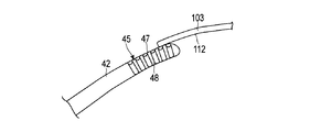
- FIG. 5 is a view of the second curved extending portion 45 (the distal end portion of the curved extending portion 40) viewed from the first width direction side.
- FIG. 6 is a cross-sectional view taken along the line VI-VI in FIG. 5 and shows a cross section perpendicular to the extending direction of the curved extending portion 40.
- the second curved extending portion 45 is provided with cutting surfaces (treatment surfaces) 47 to 49.
- the first cutting surface 47 is provided on the second curved outer surface 56 (a portion facing the second crossing direction side on the outer surface of the curved extending portion 40).
- the second cutting surface 48 is provided on the third curved outer surface 57 (the portion facing the first width direction side on the outer surface of the curved extending portion 40), and the third cutting surface 49 is the first cutting surface 49.
- 4 is provided on the curved outer surface 58 (portion facing the second width direction side on the outer surface of the curved extending portion 40). In each of the cutting surfaces 47 to 49, a plurality of grooves described later are formed.
- each of the cutting surfaces 47 to 49 extends from the distal end (the distal end surface 46) of the curved extending portion 40 toward the proximal end side.
- the first cutting surface 47 is the second curved extending portion 45 and is provided on the second curved outer surface 56. For this reason, in the projection from each of the first width direction and the second width direction, the center (O1) of the first cutting surface 47 is located on the first intersecting direction side from the curved extending portion 40. It is formed in an arc shape.
- the second curved extending portion 45 has a thickness dimension T6 in the thickness direction of the curved extending portion 40 between the first cutting surface 47 and the first curved outer surface 55.
- a thickness dimension T6 between the first cutting surface 47 and the first curved outer surface 55 is substantially the same as the thickness dimension T2.
- the second curved extending portion 45 is provided between the second cutting surface 48 (third curved outer surface 57) and the third cutting surface 49 (fourth curved outer surface 58).
- a width dimension W5 in the second width direction The width dimension W5 between the second cutting surface 48 and the third cutting surface 49 is substantially the same as the width dimension W1.
- the thickness dimension T6 (T2) in the thickness direction is the width dimension in the first width direction and the second width direction between the third curved outer surface 57 and the fourth curved outer surface 58. It is smaller than W5 (W1).
- the second cutting surface 48 is formed with a plurality of (six in this embodiment) extending grooves (first extending grooves) 63A to 63F.
- Each of the extending grooves 63A to 63F extends substantially perpendicularly to the extending direction of the curved extending portion 40.
- the extending grooves 63A to 63F extend along the thickness direction of the curved extending portion 40. Yes. Further, the extending grooves 63A to 63F are arranged in parallel in the extending direction of the curved extending portion 40.
- Each of the extending grooves 63A to 63F has an acute angle ⁇ 1 between the extending grooves adjacent to the extending direction of the curved extending portion 40 (one or two corresponding to 63A to 63F). That is, the extending direction of each of the extending grooves 63A to 63F is shifted by an acute angle ⁇ 1 with respect to the extending direction of the adjacent extending grooves (one or two corresponding to 63A to 63F). Further, the most proximal end extending groove 63F located on the most proximal side among the extending grooves 63A to 63F is defined.
- the extending direction of the most proximal end extending groove 63F has an obtuse angle ⁇ 8 with respect to the proximal end side.
- the acute angle ⁇ 1 is 3 ° and the obtuse angle ⁇ 8 is 95 °.
- each of the extending grooves 63A to 63F forms an angle ⁇ 3 with the first cutting surface 47, and the angle ⁇ 3 is 90 °. .
- the extending grooves 63A to 63F intersect at the center (O1) of the arc of the first cutting surface 47.
- Each of the extending grooves 63A to 63F has a width ⁇ 3 and a depth W3. In one embodiment, the width ⁇ 3 is 0.5 mm and the depth W3 is 0.35 mm.
- a plurality (six in this embodiment) of extending grooves (second extending grooves) 65A to 65F are formed on the third cutting surface 49.
- Each of the extended grooves (second extended grooves) 65A to 65F is substantially symmetric with the corresponding extended groove (one corresponding to 63A to 63F) with the reference plane Y2 as the central plane. For this reason, in the projection from the second width direction, the extending grooves 65A to 65F are located with respect to the arc-shaped first cutting surface 47 whose center is located on the first intersecting direction side from the curved extending portion 40. In a state orthogonal to each other, the third cutting surface 49 is extended.
- an acute angle ⁇ 1, an obtuse angle ⁇ 8, a width ⁇ 3, and a depth W3 are defined in relation to the extending grooves 65A to 65F.
- the second curved extending portion 45 extends from the bottom position of each of the extending grooves 63A to 63F to the bottom position of the corresponding extending groove (one corresponding to 65A to 65F) in the first width direction and
- the second width direction has a width direction dimension W4.
- the width direction dimension W4 is not less than 2.1 mm and not more than 2.15 mm.
- each of the relay grooves 71A to 71F extends substantially perpendicularly to the extending direction of the curved extending portion 40, and in the present embodiment, the width direction of the curved extending portion 40 (the first width direction and the second width direction). It extends along the width direction.
- One end of each of the relay grooves 71A to 71F is continuous with the corresponding extended groove (one corresponding one of 63A to 63F), and the other end of each of the relay grooves 71A to 71F is the corresponding extended groove (65A to 65F). A corresponding one of 65F).
- the relay grooves 71A to 71F have the same width ⁇ 3 as the extending grooves 63A to 63F and 65A to 65F, and a depth T5.
- the depth T5 is not less than 0.3 mm and not more than 0.35 mm.
- each bottom surface of the relay grooves 71A to 71F is formed in an arc shape having an angle ⁇ 3 / 2.
- the second curved extending portion 45 between the first curved outer surface 55 (portion facing the first crossing direction side of the outer surface) and the second cutting surface 48 in a cross section perpendicular to the extending direction. And between the 1st curved outer surface 55 and the 3rd cutting surface 49, it forms in the curved surface shape of the angle
- the curved surface portion of the corner R6 is formed over the range S1 of FIG. 3 in the longitudinal axis direction, and the curved surface portion of the corner R7 is formed over the range S2 of FIG. 3 in the longitudinal axis direction. That is, the curved surface portion of the corner R6 and the curved surface portion of the corner R7 are extended from the distal end of the ultrasonic probe 8 to the tapered portion 41 in the longitudinal axis direction, and the protruding portion (exposed portion) from the distal end of the sheath 7 in the ultrasonic probe 8 ), A curved surface portion of the corner R6 and a curved surface portion of the corner R7 are formed.
- a part of the tapered portion 41 and the curved extending portion 40 face the first crossing direction side of the outer surface and the first width direction side of the outer surface.
- a part of the tapered portion 41 and the curved extending portion 40 face the first crossing direction side of the outer surface and the first width direction side of the outer surface.
- Between the part and between the part facing the first cross direction side of the outer surface and the part facing the second width direction side of the outer surface is formed in a curved surface shape with an angle R6.
- the extending grooves (one corresponding to 63A to 63F) corresponding to each of the relay grooves 71A to 71F, And between the relay grooves 71A to 71F and the corresponding extension grooves (corresponding ones of 65A to 65F) are formed in a curved surface having an angle R8.
- the angle R8 is 0.55 mm.
- FIGS. 7 and 8 are views showing a state in which bone is being cut at the shoulder joint 100 using the ultrasonic treatment system 1.
- 7 is a view of the shoulder joint 100 viewed from the front side (chest side)
- FIG. 8 is a view of the shoulder joint 100 viewed from the back side (back side).
- the shoulder joint 100 is a joint between the humerus 101 and the scapula 102.
- the scapula 102 includes an acromion 103.
- a clavicle 105 is connected to the shoulder cap 103.
- a conrotator rotator cuff 111 is formed below the acromion 103 as tendons of the subscapular muscle 106, the supraspinatus 107, the subspinous muscle 108, and the small circular muscle 109.
- a humerus 101 is extended from the rotator cuff 111.
- a cavity 113 is formed between the lower surface 112 of the acromion 103 and the rotator cuff 111.
- the ultrasonic treatment tool 2 is used when cutting a hard tissue such as a bone in a narrow space such as a joint cavity.
- a hard tissue such as a bone in a narrow space such as a joint cavity.
- the distal end of the rigid endoscope (arthroscope) 115 is inserted into the cavity 113 between the acetabulum 103 and the rotator cuff tendon 111.
- the tip of the ultrasonic probe 8 are inserted.
- Each of the rigid endoscope 115 and the ultrasonic probe 8 is inserted from the outside of the human body into the cavity 113 through any of an insertion position on the front side, an insertion position on the side, and an insertion position on the rear side.
- the insertion location of the rigid endoscope 115 is different from the insertion location of the ultrasonic probe 8. 7 and 8, the rigid endoscope 115 is inserted into the cavity 113 from the insertion site on the front side, and the ultrasonic probe 8 is inserted into the cavity 113 from the insertion site on the side. Then, any one of the cutting surfaces 47 to 49 of the ultrasonic probe 8 is brought into contact with the lower surface 112 of the shoulder peak 103 in the cavity 113 under observation by the rigid endoscope 115.
- FIG. 9 and 10 are views showing a state in which the first cutting surface 47 of the second curved extending portion 45 of the ultrasonic probe 8 is in contact with the lower surface 112 of the acromion 103.
- FIG. 10 the first cutting surface 47 is brought into contact with the lower surface 112 of the shoulder ridge 103 at a position different from that in FIG. 9.
- the first curved extending portion 42 is bent in the first vertical direction side with respect to the probe main body portion 31 extending along the longitudinal axis C, and the second curved extending portion is provided.
- the installation portion 45 is further curved toward the first vertical direction side with respect to the first curved extension portion 42.
- the first cutting surface 47 is centered on the first intersecting direction side from the curved extending portion 40 ( It is formed in an arc shape in which O1) is located.
- a cavity 113 between the acromion 103 and the rotator cuff 111 is narrow, and the lower surface 112 of the acromion 103 is formed in a curved surface shape.
- the contact angle of the first cutting surface 47 with respect to the lower surface 112 of the accumulator 103 is different. Different. In the present embodiment, since the first curved extending portion 42 and the second curved extending portion 45 are formed as described above, the contact angle of the first cutting surface 47 with respect to the lower surface 112 of the shoulder ridge 103 changes. Even in this case, the first cutting surface 47 can be appropriately brought into contact with the lower surface 112 of the shoulder ridge 103. For example, in both FIG. 9 and FIG. 10, the first cutting surface 47 appropriately contacts the lower surface 112 of the acromion 103.
- the first cutting surface 47 is appropriately The lower surface 112 of the shoulder ridge 103 can be brought into contact.
- the first cutting surface 47 is provided on the second curved outer surface 56 of the curved extending portion 40, and the second curved outer surface 56 (the first outer circumferential surface of the curved extending portion 40 is provided). 2), the acute angle ⁇ 4 with respect to the longitudinal axis direction of the tangent at the tip is 10 ° or more and 30 ° or less (preferably 20 ° or more and 25 ° or less). By setting the acute angle ⁇ 4 to 10 ° or more and 30 ° or less (especially, 20 ° or more and 25 ° or less), the first cutting surface 47 has a shape corresponding to the lower surface 112 of the shoulder ridge 103, and any lower surface 112 of the shoulder ridge 103 is formed. Even in the position, the first cutting surface 47 can be more easily and appropriately brought into contact with the lower surface 112 of the shoulder ridge 103.
- the relay grooves 71A to 71F extend substantially perpendicular to the extending direction of the curved extending portion 40 (that is, the vibration direction due to longitudinal vibration). Since the relay grooves 71A to 71F are extended substantially perpendicular to the vibration direction due to the longitudinal vibration, the second curved extending portion 45 is longitudinally vibrated by the ultrasonic vibration while the first cutting surface 47 is in contact therewith. By doing so, the bone (osteophyte) is appropriately cut. That is, hard bone can be appropriately cut.
- the first cutting surface 47 is easily brought into contact with the hard tissue even in a joint space such as the space 113 between the acromion 103 and the rotator cuff 111, that is, in a narrow space.
- the hard structure is appropriately cut by the one cutting surface 47. That is, even in a narrow space, the accessibility to the hard tissue and the machinability of the hard tissue are ensured.
- the bone may be cut by bringing the second cutting surface 48 or the third cutting surface 49 into contact with the lower surface 112 of the shoulder ridge 103. Further, when cutting the bone (osteophyte) by bringing the first cutting surface 47 into contact with the lower surface 112 of the acromion 103, the second cutting is performed in the vicinity of the portion to be cut by the first cutting surface 47. The bone is cut by the surface 48 and the third cutting surface 49. By cutting the bone with the cutting surfaces 48 and 49, it is possible to prevent only the portion cut by the first cutting surface 47 from being dented and to prevent a step from being formed on the lower surface 112 of the shoulder peak 103. .
- the extending grooves 63A to 63F of the second cutting surface 48 and the extending grooves 65A to 65F of the third cutting surface 49 are with respect to the extending direction of the ultrasonic probe 8 (that is, the vibration direction due to longitudinal vibration). And extending substantially vertically (along the thickness direction of the curved extending portion 40). Since the extending grooves (first extending grooves) 63A to 63F extend substantially perpendicular to the vibration direction due to the longitudinal vibration, when cutting with the second cutting surface 48 using ultrasonic vibration, Bone machinability is improved.
- the extending grooves (second extending grooves) 65A to 65F extend substantially perpendicular to the vibration direction due to the longitudinal vibration, cutting is performed on the third cutting surface 49 using ultrasonic vibration. In this case, the machinability of the bone is improved.
- extending grooves (first extending grooves) 63A to 63F are extended on the second cutting surface 48 in a state orthogonal to the arc-shaped first cutting surface 47, and the third cutting surface 48 On the cutting surface 49, extending grooves (second extending grooves) 65A to 65F are extended in a state orthogonal to the arcuate first cutting surface 47. For this reason, when cutting with the 2nd cutting surface 48 or the 3rd cutting surface 49, the machinability of a bone improves.
- each of the relay grooves 71A to 71F is continuous with the corresponding extending groove (one corresponding to 63A to 63F) and the corresponding extending groove (one corresponding to 65A to 65F). For this reason, when the bone is cut with the cutting surfaces 47 to 49, the bone is cut uniformly without unevenness, and the machinability is further improved.
- each of the relay grooves 71A to 71F and the corresponding extension groove (one corresponding to 63A to 63F) and each of the relay grooves 71A to 71F are provided with an extension groove ( And a corresponding one of 65A to 65F) is formed into a curved surface having an angle R8. Therefore, between each of the relay grooves 71A to 71F and the corresponding extended groove (one corresponding one of 63A to 63F), and to the corresponding extended groove (65A to 65F) of each of the relay grooves 71A to 71F. It is effectively prevented that the bone remains without being cut between the corresponding one).
- the front end of the first diaphragm outer surface 51 is based on the base of the second diaphragm outer surface 52 (second diaphragm end position E11).
- the extension dimension L19 of the first axis-parallel outer surface 61 is larger than the extension dimension L20 of the second axis-parallel outer surface 62.
- the curved extension portion 40 and the taper portion 41 are portions facing the first crossing direction side of the outer surface ( It is difficult for the back side portion) to come into contact with a living tissue or the like other than the treatment target (the lower surface of the shoulder ridge 103). Therefore, the first cutting surface 47 can be easily moved to a position where the first cutting surface 47 can come into contact with the lower surface 112 of the shoulder ridge 103.
- the first bending start position E14 of the first bending outer surface 55 is located on the distal end side with respect to the second bending start position E15 of the second bending outer surface 56. Therefore, when the first cutting surface 47 is moved to a position where it can come into contact with the lower surface 112 of the shoulder ridge 103, the curved extension portion 40 and the taper portion 41 are portions facing the first crossing direction side of the outer surface ( The back side part) is more difficult to come into contact with a living tissue or the like other than the treatment target (the lower surface of the shoulder ridge 103). Therefore, it becomes easier to move the first cutting surface 47 to a position where it can come into contact with the lower surface 112 of the shoulder ridge 103.
- FIG. 11 shows the longitudinal vibration amplitude V and the superhigh frequency between the second vibration antinode A3 from the distal end side and the vibration antinode A2 on the most distal end side in a state where the vibrating body unit 20 vibrates longitudinally within a specified frequency range.
- the stress ⁇ due to sonic vibration is shown.
- the horizontal axis indicates the position in the longitudinal axis direction
- the vertical axis indicates the amplitude V and the stress ⁇ .
- the change in the amplitude V of the longitudinal vibration is indicated by a solid line
- the change in the stress ⁇ is indicated by a one-dot chain line.
- the tapered portion 41 is located on the distal end side from the most distal vibration node N ⁇ b> 3, and the longitudinal vibration amplitude V at the tapered portion 41. Is enlarged.
- the longitudinal vibration having an amplitude at the vibration antinode of 80 ⁇ m is expanded by the taper portion 41 into a vertical vibration having an amplitude at the vibration antinode of 140 ⁇ m to 150 ⁇ m.
- the stress ⁇ due to the ultrasonic vibration increases at a portion where the cross-sectional area perpendicular to the vibration node and the transmission direction of the ultrasonic vibration decreases, and becomes zero at the vibration antinode. Therefore, as shown in FIG. 11, the stress ⁇ increases between the vibration node N3 and the tip (E13) of the tapered portion 41.
- the dimension in the longitudinal axis direction from the proximal end (E9) to the distal end (E13) of the taper portion 41 is 8 minutes when the vibrating body unit 20 vibrates longitudinally within a specified frequency range. Of one wavelength ( ⁇ / 8).
- the first diaphragm dimension L12 between the base end (E9) and the first diaphragm end position E10 in the longitudinal axis direction is also in a state in which the vibrating body unit 20 vibrates longitudinally within a specified frequency range. Becomes larger than one-eighth wavelength.
- the entire length between the vibration node N3 and the distal end (E13) of the taper portion 41 is increased.
- the stress ⁇ due to the sonic vibration is kept substantially uniform. That is, it is effectively prevented that the stress locally increases (that is, a peak is generated) between the vibration node N3 and the tip (E13) of the tapered portion 41.
- the vibrating body unit 20 is in a specified frequency range (for example, 46 kHz).
- the stress ⁇ is kept substantially uniform at about 300 Mpa between the vibration node N3 and the tip (E13) of the tapered portion 41. That is, in the present embodiment, the stress locally increases to about 700 Mpa (for example, at the tip (E13) of the taper portion 41) between the vibration node N3 and the tip (E13) of the taper portion 41. Is prevented. Since the stress ⁇ is prevented from locally increasing, it is possible to effectively prevent damage to the ultrasonic probe 8 due to ultrasonic vibration.
- the cross-sectional center of gravity in the cross section perpendicular to the longitudinal axis C is shifted from the longitudinal axis C to the second vertical direction.
- the displacement of the cross-sectional center of gravity with respect to the longitudinal axis C in the second intersecting direction becomes large.
- the shift of the center of gravity toward the first intersecting direction due to the bending of the curved extending portion 40 with respect to the longitudinal axis direction results in the center of gravity toward the second intersecting direction due to the tapered portion 41. It is canceled by the deviation.
- the first curved outer surface 55 and the front end surface 46 are formed in a curved surface having an angle R3. Further, in the projection from the first width direction, a space between the second curved outer surface 56 and the tip surface 46 is formed in a curved shape having an angle R4. In the projection from the second intersecting direction (one side of the intersecting direction), between the third curved outer surface 57 and the distal end surface 46 and between the fourth curved outer surface 58 and the distal end surface 46. Is formed in a curved surface having an angle R5.
- the ratio of the surface (outer surface) perpendicular to the extending direction of the ultrasonic probe 8 (that is, the vibration direction of longitudinal vibration) is reduced.
- the ratio of the surface perpendicular to the vibration direction of the longitudinal vibration even if the ultrasonic probe 8 is vibrated longitudinally while the second curved extension 45 is immersed in a liquid (physiological saline), The occurrence of cavitation in the vicinity of the front end face 46 is reduced. By reducing the occurrence of cavitation, the visibility of the operator in the procedure is improved.
- the portion facing the first crossing direction side of the outer surface and the first width of the outer surface are formed in a curved surface shape with an angle R6.
- the ultrasonic probe (8) extends along the longitudinal axis (C), and transmits the ultrasonic vibration from the proximal end side to the distal end side, and the probe main body.
- the first crossing direction with respect to the probe main body when the first crossing direction (P1) is one direction that is provided on the distal end side with respect to the portion (31) and crosses the longitudinal axis (C).
- a curved extension portion (40) that extends in a state of bending to the side.
- the curved extending portion (40) has a first curved outer surface (55) facing the first intersecting direction (P1) side and a direction opposite to the first intersecting direction (P1) in the second intersecting direction ( P2), the second curved outer surface (56) facing the second intersecting direction (P2) side, the longitudinal axis (C) and the first intersecting direction (P1) and the second intersecting direction (P2)
- a third curve facing the first width direction (B1) side when two directions perpendicular to the crossing direction (P2) of the two are defined as the first width direction (B1) and the second width direction (B2).
- the first cutting surface (47) formed on the second curved outer surface (56) extends in a curved manner in the projection from each of the first width direction (B1) and the second width direction (B2). It is formed in an arc shape with the center (O1) located closer to the first intersecting direction (P1) side than the portion (40).
- the first extending grooves (63A to 63F) extend along the thickness direction of the curved extending portion (40).
- the second extending grooves (65A to 65F) are formed along the thickness direction of the curved extending portion (40).
- One end of the relay groove (71A to 71F) extended to the first cutting surface (48) is continuous with the first extension groove (63A to 63F), and the other end is the second extension groove (65A). To 65F).
Landscapes
- Health & Medical Sciences (AREA)
- Surgery (AREA)
- Life Sciences & Earth Sciences (AREA)
- Engineering & Computer Science (AREA)
- Biomedical Technology (AREA)
- Public Health (AREA)
- Veterinary Medicine (AREA)
- Nuclear Medicine, Radiotherapy & Molecular Imaging (AREA)
- General Health & Medical Sciences (AREA)
- Heart & Thoracic Surgery (AREA)
- Medical Informatics (AREA)
- Molecular Biology (AREA)
- Animal Behavior & Ethology (AREA)
- Orthopedic Medicine & Surgery (AREA)
- Dentistry (AREA)
- Oral & Maxillofacial Surgery (AREA)
- Otolaryngology (AREA)
- Surgical Instruments (AREA)
- Mechanical Engineering (AREA)
Priority Applications (4)
| Application Number | Priority Date | Filing Date | Title |
|---|---|---|---|
| CN201580027608.6A CN106456228B (zh) | 2015-01-07 | 2015-09-15 | 超声波探头及超声波处理器具 |
| EP15876928.1A EP3243466B1 (de) | 2015-01-07 | 2015-09-15 | Ultraschallsonde |
| JP2016522082A JP6001214B1 (ja) | 2015-01-07 | 2015-09-15 | 超音波プローブ |
| US15/332,550 US9730710B2 (en) | 2015-01-07 | 2016-10-24 | Ultrasonic probe and ultrasonic instrument |
Applications Claiming Priority (2)
| Application Number | Priority Date | Filing Date | Title |
|---|---|---|---|
| JP2015001840 | 2015-01-07 | ||
| JP2015-001840 | 2015-01-07 |
Related Child Applications (1)
| Application Number | Title | Priority Date | Filing Date |
|---|---|---|---|
| US15/332,550 Continuation US9730710B2 (en) | 2015-01-07 | 2016-10-24 | Ultrasonic probe and ultrasonic instrument |
Publications (1)
| Publication Number | Publication Date |
|---|---|
| WO2016111055A1 true WO2016111055A1 (ja) | 2016-07-14 |
Family
ID=56355763
Family Applications (3)
| Application Number | Title | Priority Date | Filing Date |
|---|---|---|---|
| PCT/JP2015/076187 WO2016111054A1 (ja) | 2015-01-07 | 2015-09-15 | 超音波プローブ |
| PCT/JP2015/076186 WO2016111053A1 (ja) | 2015-01-07 | 2015-09-15 | 超音波プローブ |
| PCT/JP2015/076188 WO2016111055A1 (ja) | 2015-01-07 | 2015-09-15 | 超音波プローブ |
Family Applications Before (2)
| Application Number | Title | Priority Date | Filing Date |
|---|---|---|---|
| PCT/JP2015/076187 WO2016111054A1 (ja) | 2015-01-07 | 2015-09-15 | 超音波プローブ |
| PCT/JP2015/076186 WO2016111053A1 (ja) | 2015-01-07 | 2015-09-15 | 超音波プローブ |
Country Status (5)
| Country | Link |
|---|---|
| US (3) | US9839437B2 (de) |
| EP (3) | EP3243466B1 (de) |
| JP (3) | JP6001213B1 (de) |
| CN (3) | CN106456226B (de) |
| WO (3) | WO2016111054A1 (de) |
Cited By (1)
| Publication number | Priority date | Publication date | Assignee | Title |
|---|---|---|---|---|
| WO2018078833A1 (ja) * | 2016-10-28 | 2018-05-03 | オリンパス株式会社 | 超音波プローブ |
Families Citing this family (7)
| Publication number | Priority date | Publication date | Assignee | Title |
|---|---|---|---|---|
| CN106132326B (zh) * | 2015-01-07 | 2018-11-13 | 奥林巴斯株式会社 | 超声波探头 |
| USD831834S1 (en) * | 2015-12-04 | 2018-10-23 | Sonotec Ultraschallsensorik Halle Gmbh | Ultrasonic probe |
| US10631882B2 (en) * | 2016-04-28 | 2020-04-28 | David K. Boger | Oscillating decortication burr assembly |
| WO2018078834A1 (ja) * | 2016-10-28 | 2018-05-03 | オリンパス株式会社 | 超音波プローブ |
| US11786259B1 (en) * | 2019-05-28 | 2023-10-17 | Mirus Llc | Systems and methods for ultrasonically-assisted placement of orthopedic implants |
| USD974558S1 (en) | 2020-12-18 | 2023-01-03 | Stryker European Operations Limited | Ultrasonic knife |
| CN115500902B (zh) * | 2022-10-13 | 2023-09-15 | 以诺康医疗科技(苏州)有限公司 | 一种超声手术刀 |
Citations (3)
| Publication number | Priority date | Publication date | Assignee | Title |
|---|---|---|---|---|
| JP2007531563A (ja) * | 2004-02-27 | 2007-11-08 | エシコン・エンド−サージェリィ・インコーポレイテッド | 横および縦振動を有する超音波外科ブレード |
| US20140135804A1 (en) * | 2012-11-15 | 2014-05-15 | Ethicon Endo-Surgery, Inc. | Ultrasonic and electrosurgical devices |
| JP2014533148A (ja) * | 2011-10-19 | 2014-12-11 | ソーリン ゲーエムベーハー | ソノトロード |
Family Cites Families (23)
| Publication number | Priority date | Publication date | Assignee | Title |
|---|---|---|---|---|
| JPS6266848A (ja) * | 1985-09-20 | 1987-03-26 | 住友ベークライト株式会社 | 外科手術用具 |
| AU630294B2 (en) * | 1990-05-11 | 1992-10-22 | Sumitomo Bakelite Company Limited | Surgical ultrasonic horn |
| US5205817A (en) * | 1990-05-17 | 1993-04-27 | Sumitomo Bakelite Company Limited | Surgical instrument |
| JPH07110278B2 (ja) * | 1993-03-29 | 1995-11-29 | 住友ベークライト株式会社 | 超音波手術装置 |
| CA2276316C (en) * | 1998-06-29 | 2008-02-12 | Ethicon Endo-Surgery, Inc. | Method of balancing asymmetric ultrasonic surgical blades |
| JP4253513B2 (ja) * | 2003-02-14 | 2009-04-15 | オリンパス株式会社 | 超音波処置装置 |
| US7532793B2 (en) | 2003-07-29 | 2009-05-12 | Intel Corporation | Segmented waveguide coupler |
| US7785337B2 (en) * | 2003-09-09 | 2010-08-31 | Medtronic Xomed, Inc. | Surgical micro-burring instrument and method of performing sinus surgery |
| JP2005152098A (ja) * | 2003-11-21 | 2005-06-16 | Miwatec:Kk | 超音波ハンドピ−スとこれに使用する超音波ホ−ン |
| ITTO20060113U1 (it) * | 2006-07-27 | 2008-01-28 | Cornelio Blus | Punte taglienti per chirurgia ossea ad ultrasuoni |
| US20080194999A1 (en) * | 2007-02-09 | 2008-08-14 | Norihiro Yamaha | Ultrasonic treatment apparatus and treatment method |
| WO2009049016A1 (en) * | 2007-10-10 | 2009-04-16 | Ethicon Endo-Surgery, Inc | Ultrasonic device for cutting and coagulating |
| GB0809243D0 (en) * | 2008-05-21 | 2008-06-25 | Sra Dev Ltd | Improved torsional mode tissue dissector |
| JP5430161B2 (ja) | 2008-06-19 | 2014-02-26 | オリンパスメディカルシステムズ株式会社 | 超音波手術装置 |
| US20100106173A1 (en) * | 2008-10-23 | 2010-04-29 | Hideto Yoshimine | Ultrasonic surgical device |
| US8579928B2 (en) * | 2010-02-11 | 2013-11-12 | Ethicon Endo-Surgery, Inc. | Outer sheath and blade arrangements for ultrasonic surgical instruments |
| WO2011140450A1 (en) * | 2010-05-07 | 2011-11-10 | Medicinelodge, Inc Dba Imds Co-Innovation | Surgical rasp with radiofrequency ablation |
| US20120101512A1 (en) * | 2010-10-21 | 2012-04-26 | Christopher Brian Locke | Debridement hand tool |
| EP2636382B1 (de) * | 2011-03-01 | 2016-08-03 | Olympus Corporation | Ultraschallsonde |
| US9848900B2 (en) * | 2012-12-07 | 2017-12-26 | Ethicon Llc | Ultrasonic surgical blade |
| WO2014196640A1 (ja) * | 2013-06-07 | 2014-12-11 | オリンパスメディカルシステムズ株式会社 | 超音波プローブ及び超音波処置装置 |
| US9949751B2 (en) * | 2014-02-04 | 2018-04-24 | Misonix, Inc. | Ultrasonic debrider probe |
| JP5807080B2 (ja) | 2014-02-14 | 2015-11-10 | 本田技研工業株式会社 | 車両 |
-
2015
- 2015-09-15 CN CN201580027267.2A patent/CN106456226B/zh not_active Expired - Fee Related
- 2015-09-15 CN CN201580027608.6A patent/CN106456228B/zh not_active Expired - Fee Related
- 2015-09-15 EP EP15876928.1A patent/EP3243466B1/de active Active
- 2015-09-15 WO PCT/JP2015/076187 patent/WO2016111054A1/ja active Application Filing
- 2015-09-15 EP EP15876926.5A patent/EP3243464A4/de not_active Withdrawn
- 2015-09-15 JP JP2016522079A patent/JP6001213B1/ja active Active
- 2015-09-15 CN CN201580027526.1A patent/CN106456227B/zh not_active Expired - Fee Related
- 2015-09-15 JP JP2016522064A patent/JP6001212B1/ja active Active
- 2015-09-15 WO PCT/JP2015/076186 patent/WO2016111053A1/ja active Application Filing
- 2015-09-15 EP EP15876927.3A patent/EP3243465B1/de active Active
- 2015-09-15 WO PCT/JP2015/076188 patent/WO2016111055A1/ja active Application Filing
- 2015-09-15 JP JP2016522082A patent/JP6001214B1/ja not_active Expired - Fee Related
-
2016
- 2016-10-20 US US15/298,344 patent/US9839437B2/en active Active
- 2016-10-24 US US15/332,550 patent/US9730710B2/en active Active
- 2016-10-24 US US15/332,112 patent/US9730709B2/en active Active
Patent Citations (3)
| Publication number | Priority date | Publication date | Assignee | Title |
|---|---|---|---|---|
| JP2007531563A (ja) * | 2004-02-27 | 2007-11-08 | エシコン・エンド−サージェリィ・インコーポレイテッド | 横および縦振動を有する超音波外科ブレード |
| JP2014533148A (ja) * | 2011-10-19 | 2014-12-11 | ソーリン ゲーエムベーハー | ソノトロード |
| US20140135804A1 (en) * | 2012-11-15 | 2014-05-15 | Ethicon Endo-Surgery, Inc. | Ultrasonic and electrosurgical devices |
Cited By (1)
| Publication number | Priority date | Publication date | Assignee | Title |
|---|---|---|---|---|
| WO2018078833A1 (ja) * | 2016-10-28 | 2018-05-03 | オリンパス株式会社 | 超音波プローブ |
Also Published As
| Publication number | Publication date |
|---|---|
| EP3243466B1 (de) | 2019-11-06 |
| JPWO2016111053A1 (ja) | 2017-04-27 |
| US20170035453A1 (en) | 2017-02-09 |
| JPWO2016111054A1 (ja) | 2017-04-27 |
| WO2016111054A1 (ja) | 2016-07-14 |
| CN106456228A (zh) | 2017-02-22 |
| JP6001214B1 (ja) | 2016-10-05 |
| WO2016111053A1 (ja) | 2016-07-14 |
| EP3243464A4 (de) | 2018-09-19 |
| EP3243466A4 (de) | 2018-07-11 |
| US9730709B2 (en) | 2017-08-15 |
| JP6001212B1 (ja) | 2016-10-05 |
| EP3243465B1 (de) | 2019-11-06 |
| US9839437B2 (en) | 2017-12-12 |
| EP3243464A1 (de) | 2017-11-15 |
| CN106456226A (zh) | 2017-02-22 |
| US20170035454A1 (en) | 2017-02-09 |
| EP3243465A1 (de) | 2017-11-15 |
| CN106456227A (zh) | 2017-02-22 |
| CN106456227B (zh) | 2019-07-19 |
| JP6001213B1 (ja) | 2016-10-05 |
| CN106456226B (zh) | 2019-08-23 |
| JPWO2016111055A1 (ja) | 2017-04-27 |
| US9730710B2 (en) | 2017-08-15 |
| EP3243465A4 (de) | 2018-07-18 |
| US20170035441A1 (en) | 2017-02-09 |
| EP3243466A1 (de) | 2017-11-15 |
| CN106456228B (zh) | 2019-05-31 |
Similar Documents
| Publication | Publication Date | Title |
|---|---|---|
| JP6001214B1 (ja) | 超音波プローブ | |
| JP6165389B2 (ja) | 超音波プローブ | |
| EP2859858B1 (de) | Ultraschallsonde | |
| JP5959790B1 (ja) | 超音波プローブ | |
| JP5959781B2 (ja) | 超音波プローブ及び超音波処置具 | |
| JP5690452B2 (ja) | 超音波伝達ユニット及び超音波処置装置 | |
| EP2893892B1 (de) | Ultraschallübertragungseinheit und ultraschallbehandlung | |
| JP6033519B1 (ja) | 超音波プローブと超音波処置具 | |
| JP5970142B2 (ja) | 超音波プローブ及び超音波処置具 |
Legal Events
| Date | Code | Title | Description |
|---|---|---|---|
| ENP | Entry into the national phase |
Ref document number: 2016522082 Country of ref document: JP Kind code of ref document: A |
|
| 121 | Ep: the epo has been informed by wipo that ep was designated in this application |
Ref document number: 15876928 Country of ref document: EP Kind code of ref document: A1 |
|
| NENP | Non-entry into the national phase |
Ref country code: DE |
|
| REEP | Request for entry into the european phase |
Ref document number: 2015876928 Country of ref document: EP |