WO2016111016A1 - 放射線画像生成方法および画像処理装置 - Google Patents
放射線画像生成方法および画像処理装置 Download PDFInfo
- Publication number
- WO2016111016A1 WO2016111016A1 PCT/JP2015/050549 JP2015050549W WO2016111016A1 WO 2016111016 A1 WO2016111016 A1 WO 2016111016A1 JP 2015050549 W JP2015050549 W JP 2015050549W WO 2016111016 A1 WO2016111016 A1 WO 2016111016A1
- Authority
- WO
- WIPO (PCT)
- Prior art keywords
- image processing
- weighting factor
- image
- nearest neighbor
- weighting
- Prior art date
- Legal status (The legal status is an assumption and is not a legal conclusion. Google has not performed a legal analysis and makes no representation as to the accuracy of the status listed.)
- Ceased
Links
Images



Classifications
-
- G—PHYSICS
- G06—COMPUTING OR CALCULATING; COUNTING
- G06T—IMAGE DATA PROCESSING OR GENERATION, IN GENERAL
- G06T12/00—Tomographic reconstruction from projections
- G06T12/30—Image post-processing, e.g. metal artefact correction
-
- A—HUMAN NECESSITIES
- A61—MEDICAL OR VETERINARY SCIENCE; HYGIENE
- A61B—DIAGNOSIS; SURGERY; IDENTIFICATION
- A61B6/00—Apparatus or devices for radiation diagnosis; Apparatus or devices for radiation diagnosis combined with radiation therapy equipment
- A61B6/02—Arrangements for diagnosis sequentially in different planes; Stereoscopic radiation diagnosis
- A61B6/03—Computed tomography [CT]
-
- A—HUMAN NECESSITIES
- A61—MEDICAL OR VETERINARY SCIENCE; HYGIENE
- A61B—DIAGNOSIS; SURGERY; IDENTIFICATION
- A61B6/00—Apparatus or devices for radiation diagnosis; Apparatus or devices for radiation diagnosis combined with radiation therapy equipment
- A61B6/04—Positioning of patients; Tiltable beds or the like
-
- A—HUMAN NECESSITIES
- A61—MEDICAL OR VETERINARY SCIENCE; HYGIENE
- A61B—DIAGNOSIS; SURGERY; IDENTIFICATION
- A61B6/00—Apparatus or devices for radiation diagnosis; Apparatus or devices for radiation diagnosis combined with radiation therapy equipment
- A61B6/42—Arrangements for detecting radiation specially adapted for radiation diagnosis
- A61B6/4208—Arrangements for detecting radiation specially adapted for radiation diagnosis characterised by using a particular type of detector
-
- A—HUMAN NECESSITIES
- A61—MEDICAL OR VETERINARY SCIENCE; HYGIENE
- A61B—DIAGNOSIS; SURGERY; IDENTIFICATION
- A61B6/00—Apparatus or devices for radiation diagnosis; Apparatus or devices for radiation diagnosis combined with radiation therapy equipment
- A61B6/46—Arrangements for interfacing with the operator or the patient
- A61B6/461—Displaying means of special interest
-
- A—HUMAN NECESSITIES
- A61—MEDICAL OR VETERINARY SCIENCE; HYGIENE
- A61B—DIAGNOSIS; SURGERY; IDENTIFICATION
- A61B6/00—Apparatus or devices for radiation diagnosis; Apparatus or devices for radiation diagnosis combined with radiation therapy equipment
- A61B6/52—Devices using data or image processing specially adapted for radiation diagnosis
- A61B6/5205—Devices using data or image processing specially adapted for radiation diagnosis involving processing of raw data to produce diagnostic data
-
- A—HUMAN NECESSITIES
- A61—MEDICAL OR VETERINARY SCIENCE; HYGIENE
- A61B—DIAGNOSIS; SURGERY; IDENTIFICATION
- A61B6/00—Apparatus or devices for radiation diagnosis; Apparatus or devices for radiation diagnosis combined with radiation therapy equipment
- A61B6/52—Devices using data or image processing specially adapted for radiation diagnosis
- A61B6/5258—Devices using data or image processing specially adapted for radiation diagnosis involving detection or reduction of artifacts or noise
-
- A—HUMAN NECESSITIES
- A61—MEDICAL OR VETERINARY SCIENCE; HYGIENE
- A61B—DIAGNOSIS; SURGERY; IDENTIFICATION
- A61B6/00—Apparatus or devices for radiation diagnosis; Apparatus or devices for radiation diagnosis combined with radiation therapy equipment
- A61B6/54—Control of apparatus or devices for radiation diagnosis
-
- G—PHYSICS
- G06—COMPUTING OR CALCULATING; COUNTING
- G06T—IMAGE DATA PROCESSING OR GENERATION, IN GENERAL
- G06T12/00—Tomographic reconstruction from projections
- G06T12/20—Inverse problem, i.e. transformations from projection space into object space
-
- G—PHYSICS
- G06—COMPUTING OR CALCULATING; COUNTING
- G06T—IMAGE DATA PROCESSING OR GENERATION, IN GENERAL
- G06T3/00—Geometric image transformations in the plane of the image
- G06T3/40—Scaling of whole images or parts thereof, e.g. expanding or contracting
- G06T3/4007—Scaling of whole images or parts thereof, e.g. expanding or contracting based on interpolation, e.g. bilinear interpolation
-
- A—HUMAN NECESSITIES
- A61—MEDICAL OR VETERINARY SCIENCE; HYGIENE
- A61B—DIAGNOSIS; SURGERY; IDENTIFICATION
- A61B6/00—Apparatus or devices for radiation diagnosis; Apparatus or devices for radiation diagnosis combined with radiation therapy equipment
- A61B6/02—Arrangements for diagnosis sequentially in different planes; Stereoscopic radiation diagnosis
- A61B6/025—Tomosynthesis
-
- A—HUMAN NECESSITIES
- A61—MEDICAL OR VETERINARY SCIENCE; HYGIENE
- A61B—DIAGNOSIS; SURGERY; IDENTIFICATION
- A61B6/00—Apparatus or devices for radiation diagnosis; Apparatus or devices for radiation diagnosis combined with radiation therapy equipment
- A61B6/48—Diagnostic techniques
- A61B6/486—Diagnostic techniques involving generating temporal series of image data
- A61B6/487—Diagnostic techniques involving generating temporal series of image data involving fluoroscopy
-
- G—PHYSICS
- G06—COMPUTING OR CALCULATING; COUNTING
- G06T—IMAGE DATA PROCESSING OR GENERATION, IN GENERAL
- G06T2207/00—Indexing scheme for image analysis or image enhancement
- G06T2207/10—Image acquisition modality
- G06T2207/10116—X-ray image
Definitions
- the present invention relates to a radiation image generation method for generating a radiation image and an image processing apparatus for performing image processing for generating a radiation image.
- a reconstructed image As an example of a radiation image.
- image reconstruction image reconstruction
- back projection is used.
- a general method is a pixel-driven method.
- a ray is guided from an X-ray source to the position where the X-ray detector is located through the center of the reconstructed pixel.
- the pixel value assigned to the reconstructed pixel is determined by the pixel value in the X-ray detector near the position where the surface of the X-ray detector and the oblique line intersect.
- the pixel value assigned to the reconstructed pixel is determined by linear interpolation (see, for example, Patent Documents 1 and 2).
- an interpolation method in the reconstruction there are a bilinear method, a nearest neighbor method, and the like, as shown in Patent Document 2: Japanese Patent No. 4293307 (Japanese Patent Publication No. 2005-522304).
- FIG. 5A shows a normal distribution noise image reconstructed by the filtered back projection method using the bilinear method as an interpolation method
- FIG. 5B shows the pixel value distribution. Note that, for convenience of illustration, FIG. 5A is reversed in black and white, and it should be noted that the noise is actually white spots (so-called “whiteout”) in the entire black image. As shown in FIG. 5B, it can be confirmed that the dispersion of the pixel values differs depending on the location (ROI1 and ROI2 in FIG. 5).
- reference symbol S is an X-ray tube as a light source
- reference symbol R is a reconstructed image
- reference symbol I is a detector
- the pixel R n only the pixel values of the X-ray detector I n is reflected.
- the average of the pixel values of the X-ray detectors I n + 1 and I n + 2 is reflected in the reconstructed pixel R n + 1 . In this way, S / N unevenness in the reconstructed image is generated.
- the present invention has been made in view of such circumstances, and an object thereof is to provide a radiation image generation method and an image processing apparatus capable of suppressing noise and artifacts.
- the radiographic image generation method is a radiographic image generation method for generating a radiographic image, wherein individual image processing is performed based on the result of each pixel value obtained by a plurality of different image processing algorithms.
- weighted addition is performed by combining individual image processing algorithms in order to combine a plurality of different image processing algorithms.
- a weighting coefficient for the weighted addition is set based on the result of each pixel value obtained by each image processing algorithm.
- the weight coefficient in the image processing algorithm that has an adverse effect on the region of a certain pixel value is set small, and a good result is obtained in the same region (the other)
- An example of a radiation image is a reconstructed image.
- the weighting factor is set based on the result of each backprojection pixel value obtained by a plurality of different image processing algorithms.
- the weighting coefficient in the remaining image processing algorithm can be set small by setting the weighting coefficient in the image processing algorithm large.
- the weighting coefficient in the remaining image processing algorithm can be set large by setting the weighting coefficient in the image processing algorithm small.
- the specific image processing algorithm is not particularly limited.
- a spline interpolation method may be used.
- simpler algorithms such as the nearest neighbor method, bilinear method, and spline interpolation method than the precise interpolation algorithm such as Lanczos method. It is useful to apply to an interpolation algorithm. By applying to a simple interpolation algorithm, the calculation cost is low, the load is small, and the calculation time can be reduced while suppressing noise and artifacts.
- the image processing algorithm is the nearest neighbor method and the bilinear method.
- the weighting factor setting step the weighting factor is set based on the result of each pixel value obtained by the nearest neighbor method and the bilinear method, and weighting is performed.
- the adding step it is preferable to perform weighted addition related to the nearest neighbor method and the bilinear method. In a region where an adverse effect by the nearest neighbor method is strong (a region where a high luminance difference edge exists), step artifacts can be suppressed by setting a large weighting factor in the bilinear method.
- a grid-like artifact due to S / N unevenness can be suppressed by setting a large weighting factor in the nearest neighbor method.
- simple interpolation algorithms such as the nearest neighbor method and the bilinear method have a low calculation cost, a low load, and a reduction in calculation time, while reducing step artifacts and grid-like artifacts due to S / N unevenness. Can be suppressed.
- the radiographic image is a reconstructed image, and is an X-ray
- a weighting factor is set based on the result of the backprojected pixel value obtained by the nearest neighbor method and the backprojected pixel value obtained by the bilinear method. Useful when.
- the radiation image is a reconstructed image, and the radiation is an X-ray
- the weight in the bilinear method increases as the absolute value of the difference increases. It is preferable that the coefficient be set so as to increase, and that the weight coefficient in the nearest neighbor method be increased as the absolute value of the difference becomes smaller.
- the place where the absolute value of the difference is large is regarded as a region where a high luminance difference edge exists, and the step of the edge region is suppressed by increasing the weighting coefficient (that is, increasing the weight) in the bilinear method.
- the weighting coefficient in the nearest neighbor method is increased (that is, the weight is increased) to suppress lattice artifacts due to S / N unevenness.
- the step in the edge region is suppressed.
- the weight in the remaining nearest neighbor method is set by setting a small weighting factor w bi in the bilinear method in order to suppress lattice-like artifacts due to S / N unevenness.
- the coefficient wnn is increased (that is, the weight is increased).
- lattice artifacts due to S / N unevenness are suppressed.
- the image processing apparatus is an image processing apparatus that performs image processing for generating a radiation image, and based on the result of each pixel value obtained by a plurality of different image processing algorithms,
- a weighting factor setting unit configured to set a weighting factor for weighted addition combining individual image processing algorithms; and a weighting addition unit configured to perform the weighting addition based on the set weighting factor. It is characterized by obtaining.
- the weight coefficient in the image processing algorithm that has an adverse effect in a region of a certain pixel value is set small, By setting a large weighting factor in the image processing algorithm that produces good results in the same region (the other), a radiographic image in which noise and artifacts are suppressed can be obtained.
- the weighting factor in the image processing algorithm that adversely affects a region of a certain pixel value is reduced according to the result of the pixel value obtained by each image processing algorithm.
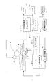
- FIG. 1 is a block diagram of the tomographic apparatus according to the embodiment
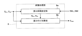
- FIG. 2 is a block diagram of an image processing unit of the tomographic apparatus according to the embodiment.
- a reconstructed image will be described as an example of a radiation image
- an X-ray will be described as an example of radiation.
- a human body will be described as an example of the subject.
- the tomography apparatus includes a top plate 1 on which a subject M is placed, an X-ray tube 2 that emits X-rays toward the subject M, and X-rays that have passed through the subject M.
- a flat panel X-ray detector hereinafter abbreviated as “FPD”) 3.
- the tomography apparatus generates a tube voltage and a tube current of the X-ray tube 2 as well as the top plate control unit 4 that controls the elevation and horizontal movement of the top plate 1, the FPD control unit 5 that controls the scanning of the FPD 3, and so on.
- An X-ray tube control unit 7 having a high voltage generation unit 6 to be generated, an A / D converter 8 that digitizes and extracts an X-ray detection signal that is a charge signal from the FPD 3, and an X output from the A / D converter 8
- An image processing unit 9 that performs various processes based on a line detection signal, a controller 10 that controls these components, a memory unit 11 that stores processed images, and an input unit that is used by an operator to perform input settings 12 and a monitor 13 for displaying processed images and the like.
- the image processing unit 9 corresponds to the image processing device in this invention.
- the top board control unit 4 horizontally moves the top board 1 to accommodate the subject M up to the imaging position, moves the top and bottom, rotates and horizontally moves the subject M to a desired position, or horizontally moves the subject M. Then, the image is picked up, or the image is moved horizontally after the image pickup is finished, and the control is performed to retract from the image pickup position.
- These controls are performed by controlling a top plate drive mechanism (not shown) including a motor and an encoder (not shown).
- the FPD control unit 5 performs control to translate the FPD 3 along the body axis z direction that is the longitudinal direction of the subject M. This control is performed by controlling an FPD drive mechanism (not shown) including a rack, pinion, motor, encoder (not shown), and the like.
- the high voltage generator 6 generates a tube voltage and a tube current for irradiating X-rays, and supplies them to the X-ray tube 2.
- the X-ray tube control unit 7 performs control to translate the X-ray tube 2 in the direction opposite to the translation of the FPD 3. This control is performed by controlling an X-ray tube driving unit (not shown) including a column, a screw rod, a motor, an encoder (not shown), and the like.
- the X-ray tube controller 7 controls the setting of the irradiation field of the collimator (not shown) on the X-ray tube 2 side.
- the irradiation field of view is set by controlling the collimator so as to irradiate fan beam-shaped X-rays extending in the body axis z direction.
- the image processing unit 9 and the controller 10 are configured by a central processing unit (CPU) and the like, and the memory unit 11 is a storage medium represented by ROM (Read-only Memory), RAM (Random-Access Memory), and the like. Etc.
- the input unit 12 includes a pointing device represented by a mouse, a keyboard, a joystick, a trackball, a touch panel, and the like.
- a program or the like for performing various image processing is written and stored in a storage medium represented by a ROM or the like, and the program or the like is read from the storage medium and executed by the CPU of the image processing unit 9. Appropriate image processing is performed.
- image processing is performed.
- setting of a weighting factor and weighting addition are performed.
- the memory unit 11 is configured to write and store each image processed by the image processing unit 9. In addition, a threshold value, which will be described later, and a weighting factor set by the weighting factor setting unit 9a (see FIG. 2) of the image processing unit 9 are written and stored in the memory unit 11.
- the FPD control unit 5 and the X-ray tube control unit 7 are also composed of a CPU or the like, similar to the image processing unit 9 and the controller 10.
- a radiological image generation method is applied to a tomosynthesis kit that performs tomography by reconstructing projection images obtained by moving the X-ray tube 2 and the FPD 3 in the directions shown in FIG.
- the image processing unit 9 includes a weighting factor setting unit 9a and a weighting addition unit 9b.
- the weighting factor setting unit 9a corresponds to the weighting factor setting unit in the present invention
- the weighting addition unit 9b corresponds to the weighting addition unit in the present invention.
- the weighting coefficient setting unit 9a sets a weighting coefficient for weighted addition obtained by combining the individual image processing algorithms based on the result of each pixel value obtained by a plurality of different image processing algorithms. A specific function of the weighting factor setting unit 9a in this embodiment will be described in detail with reference to FIG.
- the weight addition unit 9b performs weight addition based on the set weight coefficient. Then, a radiation image (reconstructed image in this embodiment) is obtained by the weighted addition.
- the specific function of the weighted addition unit 9b in this embodiment will also be described in detail with reference to FIG.
- FIG. 3 is a flowchart showing a flow of a series of radiation image generation methods according to the embodiment.
- FIG. 4 shows the absolute value of the difference regarding the backprojection pixel value on the horizontal axis and the weighting factor in the bilinear method on the vertical axis. It is a graph.
- the radiological image generation method of FIG. 3 is performed by the CPU of the image processing unit 9 executing a program.
- Step S1 Tomography
- the X-ray tube 2 and the FPD 3 are moved in opposite directions while irradiating X-rays from the X-ray tube 2 to be different from each other with respect to the subject M.
- the FPD 3 detects X-rays irradiated from the direction (projection angle).
- a plurality of X-ray images are acquired by X-rays irradiated on the subject M from different directions.
- the X-ray image is projection data projected on the detection surface of the FPD 3.
- Step S2 Reconstruction Based on the X-ray image (projected image) obtained in step S1, reconstruction is performed by a filtered back projection method using the nearest neighbor method as an interpolation method. In parallel with this, reconstruction is performed based on the X-ray image (projected image) obtained in step S1 by the filter-corrected back projection method using the bilinear method as an interpolation method.
- the filter-corrected backprojection method using the nearest neighbor method / bilinear method as an interpolation method is a known method, and thus the description thereof is omitted.
- Backprojected pixel values based on the nearest neighbor method with the I nn backprojected pixel values by the bilinear method to I bi.
- Step S3 Setting of Weighting Factor
- the weighting factor setting unit 9a (see FIG. 2) combines individual image processing algorithms based on the results of the respective pixel values obtained by a plurality of different image processing algorithms. Sets the weighting coefficient for weighted addition.
- the nearest neighbor method and the bilinear method are used as the image processing algorithm. Therefore, in this embodiment, the weighting factor setting unit 9a sets the weighting factor based on the result of each pixel value obtained by the nearest neighbor method and the bilinear method.
- step S2 the absolute value
- the weight coefficient w nn in the nearest neighbor method is represented by (1-w bi ), and the weight coefficient symbol is unified by the weight coefficient w bi in the bilinear method.
- the weighting coefficient in the bilinear method that is, the bilinear ratio at the time of mixing
- the bilinear ratio w bi is based on the difference from the backprojected pixel values I nn and I bi as follows. It is determined by equations (1) to (3).
- TH1 and TH2 are threshold values
- [a, b] means a closed section and means that ⁇ x
- as a variable is a non-decreasing function (monotonically increasing function). Accordingly, the absolute value
- of the bilinear method is set so that the weight coefficient w bi in the bilinear method increases as the absolute value
- ), the weight coefficient w bi in the bilinear method is constant at w bi 1. Further, since the graph of FIG.
- the weighting factors w bi and w nn set by the weighting factor setting unit 9a may be written and stored in the memory unit 11 (see FIG. 1).
- This step S3 corresponds to the weighting coefficient setting step in the present invention.
- Step S4 Weighted Addition
- the backprojection pixel value after weighting (after mixing) is defined as Inew .
- Inew wbi * Ibi + (1- wbi ) * Inn (4)
- of the difference from the backprojected pixel values obtained by the nearest neighbor method and the bilinear method is large is regarded as a region where a high luminance difference edge exists.
- the step of the edge region is suppressed by increasing the weighting coefficient w bi in the bilinear method (that is, increasing the weight).
- the lattice-like artifact due to S / N unevenness is increased by increasing the weighting factor w nn in the nearest neighbor method (that is, increasing the weight).
- This step S4 corresponds to the weighted addition step in the present invention.
- the (4) By arranging the backprojected pixel values I new new after weighting obtained by the equation (after mixing) for each pixel to obtain the (reconstructed image in this case) the radiation image.
- a radiation image (reconstructed image) is written in the memory unit 11 and stored.
- a weighting factor is set based on the result of each pixel value obtained by a plurality of different image processing algorithms (nearest neighbor method and bilinear method in this embodiment), and the set weighting factor is set. It is a feature of the present invention to perform weighted addition combining individual image processing algorithms based on the above.
- Patent Document 2 Japanese Patent No. 4293307 (Special Table No. 2005-522304) discloses a bilinear method and a nearest neighbor method as an interpolation method in reconstruction, but does not suggest weighted addition thereof. Please keep in mind.
- weighted addition is performed by combining individual image processing algorithms in order to combine a plurality of different image processing algorithms (in this embodiment, the nearest neighbor method and the bilinear method). Therefore, the result of each pixel value obtained by each image processing algorithm (in this embodiment, the backprojected pixel value I nn obtained by the nearest neighbor method and the backprojected pixel value I bi obtained by the bilinear method) Is set based on the absolute value
- the weighting coefficient in the image processing algorithm that has an adverse effect in a certain pixel value region is set to be small.
- a radiation image (reconstructed image in the present embodiment) in which noise and artifacts are suppressed can be obtained by setting a large weighting factor in the image processing algorithm that produces good results in the same region (the other).
- an example of the radiation image is a reconstructed image.
- the weight coefficient Set based on the result of each backprojection pixel value obtained by a plurality of different image processing algorithms (in this embodiment, the absolute value of the difference
- the individual weighting factors are set in cooperation with each other.
- the weighting coefficient in the remaining image processing algorithm can be set small by setting the weighting coefficient in the image processing algorithm large.
- the weighting coefficient in the remaining image processing algorithm can be set large by setting the weighting coefficient in the image processing algorithm small.
- the image processing algorithm is the nearest neighbor method and the bilinear method
- the weighting factor setting step (step S3) the result of each pixel value obtained by the nearest neighbor method and the bilinear method (this embodiment)
- the weighting factors w nn and w bi are set, and in the weighted addition step (step S4), weighted addition related to the nearest neighbor method and the bilinear method is performed.
- a step artifact can be suppressed by setting a large weighting factor w bi in the bilinear method.
- the grid-like artifact due to S / N unevenness can be suppressed by setting a large weighting factor wnn in the nearest neighbor method. Can do.
- simple interpolation algorithms such as the nearest neighbor method and the bilinear method have a low calculation cost, a low load, and a reduction in calculation time, while reducing step artifacts and grid-like artifacts due to S / N unevenness. Can be suppressed.
- the radiographic image is a reconstructed image, is an X-ray, and is the result of the backprojection pixel value I nn obtained by the nearest neighbor method and the backprojection pixel value I bi obtained by the bilinear method (this embodiment) Then, it is useful when setting the weighting factors w nn and w bi based on the absolute value of the difference
- the radiation image is a reconstructed image, and the radiation is an X-ray
- set as the weighting factor w bi in the bilinear method increases as the increase, the absolute value of the difference
- the weighting factor wnn at Where the absolute value
- each weighting factor in cooperation as described below. That is, the weighting factor corresponding to the nearest neighbor method and the bilinear method takes a non-negative value of 1 or less, and as described again, the weighting factor in the nearest neighbor method is set to w nn, and the weighting factor in the bilinear method is used.
- the weighting factor w bi in the remaining bilinear method is increased (that is, the weight is increased).
- the step in the edge region is suppressed.
- the weight coefficient w bi in the bilinear method is set to be small in order to suppress lattice artifacts due to S / N unevenness.
- the weight coefficient wnn in the nearest neighbor method is increased (that is, the weight is increased). As a result, lattice artifacts due to S / N unevenness are suppressed.
- the image processing apparatus image processing unit 9) according to the present embodiment, the result of the pixel value obtained by each image processing algorithm (in this embodiment, the nearest neighbor method and the bilinear method) (in this embodiment).
- ) of the difference between the backprojected pixel value I nn obtained by the nearest neighbor method and the backprojected pixel value I bi obtained by the bilinear method Radiation images that suppress noise and artifacts by setting a small weighting factor in the image processing algorithm that adversely affects and setting a large weighting factor in the image processing algorithm that produces good results in the same region (the other) ( In this embodiment, a reconstructed image) can be obtained.
- FIGS. 7 (a) to 7 (c) show the results of experiments on the shoulder when the subject is a human body
- FIG. 7 (a) is an image of the nearest neighbor method
- FIG. 7 (b) is an image of the method of the present invention
- 8 (a) to 8 (c) are experimental results when the subject is other than a human body.
- FIG. 8 (a) is an image of the nearest neighbor method
- FIG. 8 (b) is bilinear.
- FIG. 8C is an image of the method of the present invention.
- FIG. 7B it can be confirmed that lattice artifacts due to S / N unevenness appear in the bilinear method.
- FIG. 7C it can be confirmed that the technique of the present invention has improved the S / N unevenness without the appearance of the lattice artifacts due to the S / N unevenness.
- FIG. 8A it can be confirmed that a step artifact appears in the vicinity of the edge by the nearest neighbor method in a portion surrounded by a white frame.
- FIG. 8C it can be confirmed that the method of the present invention can maintain the natural appearance of the image near the edge without any step artifacts.
- the present invention is not limited to the above embodiment, and can be modified as follows.
- X-rays are taken as an example of radiation, but radiation other than X-rays (for example, ⁇ rays, ⁇ rays, ⁇ rays, etc.) may be used.
- the reconstructed image is taken as an example of the radiation image, but the image processing does not necessarily have to be back projection in the reconstruction. You may apply to image processing, such as rotation and expansion / reduction.
- the imaging was represented by tomography, but it may be applied to fluoroscopy in which radiation is irradiated with a dose lower than that in imaging and the radiation image is monitored in real time.
- the image processing apparatus (in the embodiment, the image processing unit 9) is incorporated in a fluoroscopic apparatus such as a tomographic apparatus, but may be a single image processing apparatus.
- the tomographic technique to be applied is not particularly limited.
- tomography that rotates around the body axis of the subject or one end of a curved C-arm holds the X-ray tube and the other end You may apply to the tomography which hold
- radiation other than X-rays may be used.
- the image processing algorithms are the nearest neighbor method and the bilinear method, and the individual image processing algorithms are combined to combine the two image processing algorithms composed of the nearest neighbor method and the bilinear method.
- weighted addition is performed, the number of image processing algorithms is not particularly limited as long as it is plural.
- a spline interpolation method may be combined in addition to the nearest neighbor method or the bilinear method, and the number of image processing algorithms may be three or more.
- the weighting factors corresponding to each image processing algorithm are set in cooperation with each other, but the weighting factors may be set independently.
- the remaining weighting factor may be variably set regardless of the one weighting factor, or conversely, while the one weighting factor is variably set, The remaining weighting factor values may be fixed regardless of the weighting factor.
- the image processing algorithm is the nearest neighbor method and the bilinear method, but the image processing algorithm is not limited to the nearest neighbor method or the bilinear method.
- Lanczos method or spline interpolation method may be used.
- simpler algorithms such as the nearest neighbor method, bilinear method, and spline interpolation method than the precise interpolation algorithm such as Lanczos method. It is useful to apply to an interpolation algorithm. By applying to a simple interpolation algorithm, the calculation cost is low, the load is small, and the calculation time can be reduced while suppressing noise and artifacts.
- the weighting factor setting means (weighting factor setting unit 9a in the embodiment) is configured by the CPU or the like so that the weighting factor is automatically set.
- the weighting factor is not necessarily set automatically. There is no need.
- the weighting factor setting means is configured by a pointing device such as the input unit 12 in FIG. 1, and the result of each pixel value obtained by each image processing algorithm is displayed on the monitor, and based on the display result on the monitor The weighting factor may be manually set by the operator.
- the result of each pixel value obtained by each image processing algorithm is the difference between the pixel values (in the embodiment, the backprojected pixel value I nn obtained by the nearest neighbor method and the bilinear method).
- ) of the difference from the back-projected pixel value I bi obtained in the above is not limited to the pixel value difference.
- a pixel value ratio may be obtained, and a weighting factor may be set based on the pixel value ratio.
- the weighting factor is constant in the section below the threshold TH1 and in the section exceeding the threshold TH2, and continuously increases in the open space of the threshold TH1 and TH2.
- the weighting factor is not limited to the form of FIG. Regardless of the threshold value, the weighting factor may be set by continuously increasing or decreasing, or the weighting factor may be set by increasing or decreasing the weighting factor with a trigonometric function or a higher-order polynomial. Further, the weighting coefficient need not be a continuous function, and may be set by increasing or decreasing the weighting coefficient stepwise.
- weighting factor setting unit 9b ... weighted addition unit I nn ... recently backprojected pixel values obtained by the backprojected pixel values I bi ... bilinear method obtained by the neighbor algorithm w nn ... nearest neighbors weight coefficient in the weight coefficient w bi ... bilinear method of TH1, TH2 ... threshold I new new ... backprojected pixel values of the weighted
Landscapes
- Health & Medical Sciences (AREA)
- Life Sciences & Earth Sciences (AREA)
- Engineering & Computer Science (AREA)
- Medical Informatics (AREA)
- Physics & Mathematics (AREA)
- Biomedical Technology (AREA)
- Animal Behavior & Ethology (AREA)
- Biophysics (AREA)
- High Energy & Nuclear Physics (AREA)
- Veterinary Medicine (AREA)
- Nuclear Medicine, Radiotherapy & Molecular Imaging (AREA)
- Optics & Photonics (AREA)
- Pathology (AREA)
- Radiology & Medical Imaging (AREA)
- Public Health (AREA)
- Heart & Thoracic Surgery (AREA)
- Molecular Biology (AREA)
- Surgery (AREA)
- General Health & Medical Sciences (AREA)
- General Physics & Mathematics (AREA)
- Theoretical Computer Science (AREA)
- Computer Vision & Pattern Recognition (AREA)
- Human Computer Interaction (AREA)
- Apparatus For Radiation Diagnosis (AREA)
- Image Processing (AREA)
- Algebra (AREA)
- Mathematical Analysis (AREA)
- Mathematical Optimization (AREA)
- Mathematical Physics (AREA)
- Pure & Applied Mathematics (AREA)
Abstract
Description
すなわち、この発明に係る放射線画像生成方法は、放射線画像を生成する放射線画像生成方法であって、互いに異なる複数の画像処理アルゴリズムで得られた各々の画素値の結果に基づいて、個々の画像処理アルゴリズムを結合した重み付け加算の重み係数を設定する重み係数設定工程と、設定された当該重み係数に基づいて当該重み付け加算を行う重み付け加算工程とを備え、当該重み付け加算により前記放射線画像を得ることを特徴とするものである。
図1に示すように、X線管2およびFPD3を互いに逆方向に平行移動させつつ、X線管2からX線を照射することで、被検体Mに対して互いに異なる方向(投影角度)から照射されたX線をFPD3が検出する。FPD3が検出することによって、被検体Mに対して互いに異なる方向からそれぞれ照射されたX線による複数のX線画像を取得する。X線画像は、FPD3の検出面に投影された投影データである。
ステップS1で得られたX線画像(投影画像)に基づいて、最近傍法を補間方法としたフィルタ補正逆投影法によって再構成を行う。それと並行して、ステップS1で得られたX線画像(投影画像)に基づいて、バイリニア法を補間方法としたフィルタ補正逆投影法によって再構成を行う。最近傍法・バイリニア法を補間方法としたフィルタ補正逆投影法については公知の手法であるので、その説明を省略する。最近傍法による逆投影画素値をInnとするとともに、バイリニア法による逆投影画素値をIbiとする。
重み係数設定部9a(図2を参照)は、互いに異なる複数の画像処理アルゴリズムで得られた各々の画素値の結果に基づいて、個々の画像処理アルゴリズムを結合した重み付け加算の重み係数を設定する。本実施例では、画像処理アルゴリズムとして最近傍法およびバイリニア法を用いる。よって、本実施例では、重み係数設定部9aは、最近傍法およびバイリニア法で得られた各々の画素値の結果に基づいて、重み係数を設定する。
wbi=(|Ibi-Inn|-TH1)/(TH2-TH1) TH1<|Ibi-Inn|<TH2のとき …(2)
wbi=1 TH2<|Ibi-Inn|のとき …(3)
重み付け加算部9b(図2を参照)は、ステップS3で設定された重み係数wbi,wnn(=1-wbi)に基づいて下記(4)式の重み付け加算を行う。重み付け後(混合後)の逆投影画素値をInewとする。
本発明の手法(最近傍法およびバイリニア法の重み付け加算)の結果について、図7および図8を参照して説明する。また、本発明の手法の結果との比較のために、最近傍法並びにバイリニア法も併せて図示する。図7(a)~図7(c)は、被検体を人体としたときの肩での実験結果であって、図7(a)は最近傍法の画像であり、図7(b)はバイリニア法の画像であり、図7(c)は本発明の手法の画像である。また、図8(a)~図8(c)は、被検体が人体以外のときの実験結果であって、図8(a)は最近傍法の画像であり、図8(b)はバイリニア法の画像であり、図8(c)は本発明の手法の画像である。
9a … 重み係数設定部
9b … 重み付け加算部
Inn … 最近傍法で得られた逆投影画素値
Ibi … バイリニア法で得られた逆投影画素値
wnn … 最近傍法での重み係数
wbi … バイリニア法での重み係数
TH1,TH2 … 閾値
Inew … 重み付け後の逆投影画素値
Claims (8)
- 放射線画像を生成する放射線画像生成方法であって、
互いに異なる複数の画像処理アルゴリズムで得られた各々の画素値の結果に基づいて、個々の画像処理アルゴリズムを結合した重み付け加算の重み係数を設定する重み係数設定工程と、
設定された当該重み係数に基づいて当該重み付け加算を行う重み付け加算工程と
を備え、
当該重み付け加算により前記放射線画像を得ることを特徴とする放射線画像生成方法。 - 請求項1に記載の放射線画像生成方法において、
前記放射線画像は再構成画像であって、
前記重み係数設定工程では、互いに異なる複数の画像処理アルゴリズムで得られた各々の逆投影画素値の結果に基づいて、前記重み係数を設定することを特徴とする放射線画像生成方法。 - 請求項1または請求項2に記載の放射線画像生成方法において、
前記画像処理アルゴリズム毎に対応する前記重み係数は1以下の非負の値をとり、
nを2以上の整数とし、個々の重み係数をw1,w2,…,wnとすると、
w1+w2+…+wn=1を満たすように個々の重み係数をそれぞれ設定することを特徴とする放射線画像生成方法。 - 請求項1から請求項3のいずれかに記載の放射線画像生成方法において、
前記画像処理アルゴリズムは、最近傍法およびバイリニア法であって、
前記重み係数設定工程では、前記最近傍法および前記バイリニア法で得られた各々の画素値の結果に基づいて、前記重み係数を設定し、
前記重み付け加算工程では、前記最近傍法および前記バイリニア法に関する重み付け加算を行うことを特徴とする放射線画像生成方法。 - 請求項4に記載の放射線画像生成方法において、
前記放射線画像は再構成画像であるとともに、前記放射線はX線であって、
前記重み係数設定工程では、前記最近傍法で得られた逆投影画素値および前記バイリニア法で得られた逆投影画素値の結果に基づいて、前記重み係数を設定することを特徴とする放射線画像生成方法。 - 請求項5に記載の放射線画像生成方法において、
前記重み係数設定工程では、前記最近傍法で得られた逆投影画素値と前記バイリニア法で得られた逆投影画素値との差分の絶対値に基づいて、当該差分の絶対値が大きくなるのにしたがって前記バイリニア法での重み係数が大きくなるように設定し、当該差分の絶対値が小さくなるのにしたがって前記最近傍法での重み係数が大きくなるように設定することを特徴とする放射線画像生成方法。 - 請求項6に記載の放射線画像生成方法において、
前記最近傍法および前記バイリニア法に対応する前記重み係数は1以下の非負の値をとり、
前記最近傍法での重み係数をwnnとするとともに、前記バイリニア法での重み係数をwbiとすると、
wnn+wbi=1を満たすように個々の重み係数をそれぞれ設定することを特徴とする放射線画像生成方法。 - 放射線画像を生成するための画像処理を行う画像処理装置であって、
互いに異なる複数の画像処理アルゴリズムで得られた各々の画素値の結果に基づいて、個々の画像処理アルゴリズムを結合した重み付け加算の重み係数を設定する重み係数設定手段と、
設定された当該重み係数に基づいて当該重み付け加算を行う重み付け加算手段と
を備え、
当該重み付け加算により前記放射線画像を得ることを特徴とする画像処理装置。
Priority Applications (4)
| Application Number | Priority Date | Filing Date | Title |
|---|---|---|---|
| PCT/JP2015/050549 WO2016111016A1 (ja) | 2015-01-09 | 2015-01-09 | 放射線画像生成方法および画像処理装置 |
| JP2016568258A JP6460125B2 (ja) | 2015-01-09 | 2015-01-09 | 放射線画像生成方法および画像処理装置 |
| US15/541,962 US10950012B2 (en) | 2015-01-09 | 2015-01-09 | Radiation image generation method and image processing device |
| CN201580072820.4A CN107205710B (zh) | 2015-01-09 | 2015-01-09 | 放射线图像生成方法以及图像处理装置 |
Applications Claiming Priority (1)
| Application Number | Priority Date | Filing Date | Title |
|---|---|---|---|
| PCT/JP2015/050549 WO2016111016A1 (ja) | 2015-01-09 | 2015-01-09 | 放射線画像生成方法および画像処理装置 |
Publications (1)
| Publication Number | Publication Date |
|---|---|
| WO2016111016A1 true WO2016111016A1 (ja) | 2016-07-14 |
Family
ID=56355736
Family Applications (1)
| Application Number | Title | Priority Date | Filing Date |
|---|---|---|---|
| PCT/JP2015/050549 Ceased WO2016111016A1 (ja) | 2015-01-09 | 2015-01-09 | 放射線画像生成方法および画像処理装置 |
Country Status (4)
| Country | Link |
|---|---|
| US (1) | US10950012B2 (ja) |
| JP (1) | JP6460125B2 (ja) |
| CN (1) | CN107205710B (ja) |
| WO (1) | WO2016111016A1 (ja) |
Cited By (2)
| Publication number | Priority date | Publication date | Assignee | Title |
|---|---|---|---|---|
| KR20220049003A (ko) * | 2019-08-16 | 2022-04-20 | 어답틱스 리미티드 | X선 단층촬영 시스템 및 방법 |
| JPWO2023204006A1 (ja) * | 2022-04-21 | 2023-10-26 |
Families Citing this family (2)
| Publication number | Priority date | Publication date | Assignee | Title |
|---|---|---|---|---|
| US10388000B2 (en) * | 2014-09-15 | 2019-08-20 | Analogic Corporation | Noise reduction in radiation image |
| CN113017662B (zh) * | 2021-01-28 | 2022-06-14 | 明峰医疗系统股份有限公司 | 一种ct图像的混叠伪影去除方法及系统、ct扫描仪 |
Citations (4)
| Publication number | Priority date | Publication date | Assignee | Title |
|---|---|---|---|---|
| JP2002150266A (ja) * | 2000-11-08 | 2002-05-24 | Hitachi Medical Corp | 画像処理装置 |
| JP2003153893A (ja) * | 2001-11-21 | 2003-05-27 | Hitachi Medical Corp | 断層写真像の作成装置 |
| JP2004313391A (ja) * | 2003-04-15 | 2004-11-11 | Shimadzu Corp | 断層再構成装置およびそれを用いた断層撮影装置 |
| JP2005522304A (ja) * | 2002-04-15 | 2005-07-28 | ゼネラル・エレクトリック・カンパニイ | 投影法及び逆投影法並びにその実行アルゴリズム |
Family Cites Families (11)
| Publication number | Priority date | Publication date | Assignee | Title |
|---|---|---|---|---|
| JP2670635B2 (ja) * | 1989-10-19 | 1997-10-29 | 富士写真フイルム株式会社 | エネルギーサブトラクション画像の表示方法および装置 |
| US6748098B1 (en) * | 1998-04-14 | 2004-06-08 | General Electric Company | Algebraic reconstruction of images from non-equidistant data |
| US6137856A (en) * | 1998-12-14 | 2000-10-24 | General Electric Company | Generic architectures for backprojection algorithm |
| US6272200B1 (en) * | 1999-07-28 | 2001-08-07 | Arch Development Corporation | Fourier and spline-based reconstruction of helical CT images |
| US6285732B1 (en) * | 1999-11-16 | 2001-09-04 | General Electric Company | Methods and apparatus for adaptive interpolation reduced view CT scan |
| US6339632B1 (en) * | 1999-12-23 | 2002-01-15 | Ge Medical Systems Global Technology Company, Llc | Multi slice single filtering helical weighting method and apparatus to use the same |
| US6980681B1 (en) * | 2000-04-24 | 2005-12-27 | Ge Medical Systems Global Technology Company, Llc | Methods and apparatus for helical reconstruction for multislice CT scan |
| US6587537B1 (en) * | 2002-04-01 | 2003-07-01 | Ge Medical Systems Global Technology Company, Llc | Methods and apparatus for multi-slice image reconstruction |
| US6775347B2 (en) * | 2002-05-29 | 2004-08-10 | Ge Medical Systems Global Technology Company | Methods and apparatus for reconstructing an image of an object |
| US6845144B2 (en) * | 2003-02-08 | 2005-01-18 | Ge Medical Systems Global Technology Company, Llc | Three dimensional back projection method and an X-ray CT apparatus |
| US8116426B2 (en) * | 2008-11-11 | 2012-02-14 | Kabushiki Kaisha Toshiba | Computed tomography device and method using circular-pixel position-adaptive interpolation |
-
2015
- 2015-01-09 US US15/541,962 patent/US10950012B2/en active Active
- 2015-01-09 WO PCT/JP2015/050549 patent/WO2016111016A1/ja not_active Ceased
- 2015-01-09 JP JP2016568258A patent/JP6460125B2/ja active Active
- 2015-01-09 CN CN201580072820.4A patent/CN107205710B/zh active Active
Patent Citations (4)
| Publication number | Priority date | Publication date | Assignee | Title |
|---|---|---|---|---|
| JP2002150266A (ja) * | 2000-11-08 | 2002-05-24 | Hitachi Medical Corp | 画像処理装置 |
| JP2003153893A (ja) * | 2001-11-21 | 2003-05-27 | Hitachi Medical Corp | 断層写真像の作成装置 |
| JP2005522304A (ja) * | 2002-04-15 | 2005-07-28 | ゼネラル・エレクトリック・カンパニイ | 投影法及び逆投影法並びにその実行アルゴリズム |
| JP2004313391A (ja) * | 2003-04-15 | 2004-11-11 | Shimadzu Corp | 断層再構成装置およびそれを用いた断層撮影装置 |
Cited By (6)
| Publication number | Priority date | Publication date | Assignee | Title |
|---|---|---|---|---|
| KR20220049003A (ko) * | 2019-08-16 | 2022-04-20 | 어답틱스 리미티드 | X선 단층촬영 시스템 및 방법 |
| JP2022544691A (ja) * | 2019-08-16 | 2022-10-20 | アダプティックス リミテッド | X線断層撮影システム及び方法 |
| US12008705B2 (en) | 2019-08-16 | 2024-06-11 | Adaptix Ltd | X-ray tomography system and method |
| JP7592696B2 (ja) | 2019-08-16 | 2024-12-02 | アダプティクス リミテッド | X線断層撮影システム及び方法 |
| KR102926005B1 (ko) | 2019-08-16 | 2026-02-11 | 어답틱스 리미티드 | X선 단층촬영 시스템 및 방법 |
| JPWO2023204006A1 (ja) * | 2022-04-21 | 2023-10-26 |
Also Published As
| Publication number | Publication date |
|---|---|
| CN107205710A (zh) | 2017-09-26 |
| JPWO2016111016A1 (ja) | 2017-08-31 |
| JP6460125B2 (ja) | 2019-01-30 |
| CN107205710B (zh) | 2021-02-19 |
| US20180025513A1 (en) | 2018-01-25 |
| US10950012B2 (en) | 2021-03-16 |
Similar Documents
| Publication | Publication Date | Title |
|---|---|---|
| JP5106978B2 (ja) | X線ct装置 | |
| JP4508836B2 (ja) | コンピュータ断層撮影イメージングシステムにおけるアーチファクトを低減するための方法及び装置 | |
| US9202296B2 (en) | Metal artifacts reduction for cone beam CT | |
| JP6122269B2 (ja) | 画像処理装置、画像処理方法、及びプログラム | |
| JP4350738B2 (ja) | X線断層撮影装置およびアーチファクトの低減方法 | |
| JP4646810B2 (ja) | 断層撮影像の再構成方法及び断層撮影装置 | |
| WO2016017534A1 (ja) | X線撮像装置および画像再構成方法 | |
| WO2012164921A1 (ja) | 放射線断層画像生成方法および放射線断層画像生成プログラム | |
| US20190139272A1 (en) | Method and apparatus to reduce artifacts in a computed-tomography (ct) image by iterative reconstruction (ir) using a cost function with a de-emphasis operator | |
| CN107430765A (zh) | 用于对计算机断层摄影进行引导去噪的系统和方法 | |
| JP6460125B2 (ja) | 放射線画像生成方法および画像処理装置 | |
| JP7799150B2 (ja) | 画像の散乱線補正のためのノイズおよびアーティファクト低減 | |
| WO2013161443A1 (ja) | X線ct装置及び画像再構成方法 | |
| JP2011019801A (ja) | 断層撮影装置 | |
| JP7483654B2 (ja) | 医用画像処理装置および医用画像処理方法 | |
| WO2016132880A1 (ja) | 演算装置、x線ct装置、及び画像再構成方法 | |
| US10398392B2 (en) | X-ray CT apparatus, image processing device and image reconstruction method | |
| US20120275561A1 (en) | Methods and apparatus for ct smoothing to reduce artifacts | |
| JP6051393B2 (ja) | ポアソンノイズ除去装置、ポアソンノイズ除去方法、及びx線撮影装置 | |
| WO2017130657A1 (ja) | X線ct装置、撮影条件設定方法及び撮影条件設定プログラム | |
| CN111344742A (zh) | 针对多种不同类型的投影数据每个体素具有一次几何计算的单个ct反投影器 | |
| JP2013027520A (ja) | 画像生成方法、画像生成装置及びプログラム並びにx線ct装置 | |
| JP6875960B2 (ja) | X線ct装置 | |
| Chen et al. | A semi-stationary CT system | |
| WO2015045165A1 (ja) | 放射線断層画像処理方法および放射線断層撮影装置 |
Legal Events
| Date | Code | Title | Description |
|---|---|---|---|
| 121 | Ep: the epo has been informed by wipo that ep was designated in this application |
Ref document number: 15876891 Country of ref document: EP Kind code of ref document: A1 |
|
| ENP | Entry into the national phase |
Ref document number: 2016568258 Country of ref document: JP Kind code of ref document: A |
|
| WWE | Wipo information: entry into national phase |
Ref document number: 15541962 Country of ref document: US |
|
| NENP | Non-entry into the national phase |
Ref country code: DE |
|
| 122 | Ep: pct application non-entry in european phase |
Ref document number: 15876891 Country of ref document: EP Kind code of ref document: A1 |