WO2016110902A1 - スクリュー真空ポンプ - Google Patents
スクリュー真空ポンプ Download PDFInfo
- Publication number
- WO2016110902A1 WO2016110902A1 PCT/JP2015/006242 JP2015006242W WO2016110902A1 WO 2016110902 A1 WO2016110902 A1 WO 2016110902A1 JP 2015006242 W JP2015006242 W JP 2015006242W WO 2016110902 A1 WO2016110902 A1 WO 2016110902A1
- Authority
- WO
- WIPO (PCT)
- Prior art keywords
- curve
- screw
- arc
- helical teeth
- vacuum pump
- Prior art date
- Legal status (The legal status is an assumption and is not a legal conclusion. Google has not performed a legal analysis and makes no representation as to the accuracy of the status listed.)
- Ceased
Links
Images



Classifications
-
- F—MECHANICAL ENGINEERING; LIGHTING; HEATING; WEAPONS; BLASTING
- F04—POSITIVE - DISPLACEMENT MACHINES FOR LIQUIDS; PUMPS FOR LIQUIDS OR ELASTIC FLUIDS
- F04C—ROTARY-PISTON, OR OSCILLATING-PISTON, POSITIVE-DISPLACEMENT MACHINES FOR LIQUIDS; ROTARY-PISTON, OR OSCILLATING-PISTON, POSITIVE-DISPLACEMENT PUMPS
- F04C18/00—Rotary-piston pumps specially adapted for elastic fluids
- F04C18/08—Rotary-piston pumps specially adapted for elastic fluids of intermeshing-engagement type, i.e. with engagement of co-operating members similar to that of toothed gearing
- F04C18/12—Rotary-piston pumps specially adapted for elastic fluids of intermeshing-engagement type, i.e. with engagement of co-operating members similar to that of toothed gearing of other than internal-axis type
- F04C18/14—Rotary-piston pumps specially adapted for elastic fluids of intermeshing-engagement type, i.e. with engagement of co-operating members similar to that of toothed gearing of other than internal-axis type with toothed rotary pistons
- F04C18/16—Rotary-piston pumps specially adapted for elastic fluids of intermeshing-engagement type, i.e. with engagement of co-operating members similar to that of toothed gearing of other than internal-axis type with toothed rotary pistons with helical teeth, e.g. chevron-shaped, screw type
-
- F—MECHANICAL ENGINEERING; LIGHTING; HEATING; WEAPONS; BLASTING
- F04—POSITIVE - DISPLACEMENT MACHINES FOR LIQUIDS; PUMPS FOR LIQUIDS OR ELASTIC FLUIDS
- F04C—ROTARY-PISTON, OR OSCILLATING-PISTON, POSITIVE-DISPLACEMENT MACHINES FOR LIQUIDS; ROTARY-PISTON, OR OSCILLATING-PISTON, POSITIVE-DISPLACEMENT PUMPS
- F04C25/00—Adaptations of pumps for special use of pumps for elastic fluids
- F04C25/02—Adaptations of pumps for special use of pumps for elastic fluids for producing high vacuum
Definitions
- the present invention is provided with a pair of screw rotors each having helical teeth with opposite twist directions and equal pitches, and the pair of screw rotors are stored in a casing in a non-contacting state and are synchronized with each other.
- the present invention relates to a screw vacuum pump that draws air from one end of a casing and discharges it from the other end by rotation.
- This type of screw vacuum pump is known from Patent Document 1, for example.
- the axial perpendicular cross-sectional shape of the helical tooth constitutes the root of the first arc around the rotation center of the screw rotor and the rotation center of the screw rotor constituting the tooth tip.
- the first curve is created by an epitrochoid curve created at a point on the second arc of the other screw rotor in the pair
- the second curve is created by a virtual rack composed of a predetermined curve. ing.
- This type of screw vacuum pump traps and compresses the gas sucked from the intake port of the casing between the screw rotor and the casing, and discharges it from the discharge port of the casing.
- the gap between the tooth surfaces of both helical teeth is increased so that the helical teeth do not interfere with each other, the reverse flow rate of the gas flowing back through this gap increases, leading to a decrease in pumping capacity. .
- the gap between the tooth surfaces of the helical teeth when the pair of screw rotors are engaged with each other in a non-contact manner is taken into consideration in consideration of the thermal expansion and processing accuracy according to the use environment of the screw vacuum pump. It is necessary to design so as to be as small and as small as possible (for example, 0.05 mm).
- the gap between the helical teeth of both screw rotors is wide at the rotation center side. It became clear that it became narrow as it went to the outer peripheral side. This is considered to be caused by the difference in the pitch angle ( ⁇ p) of the helical teeth at an arbitrary radial distance (R) from the rotation center of the screw rotor.
- the inventors of the present invention have made extensive studies and calculated the correction angle ( ⁇ ) according to the pitch angle ( ⁇ p) at the distance (R) from the rotation center of the screw rotor, and based on this, the epitrochoid When the coordinates of the curve are corrected, it has been found that the gap between the tooth surfaces of both helical teeth can be made equal over the entire length in the radial direction.
- the present invention has been made based on the above knowledge, and provides a screw vacuum pump in which the gaps between the tooth surfaces of both helical teeth when the pair of screw rotors mesh with each other in a non-contact manner are the same. That is the subject.
- a pair of screw rotors each having spiral teeth with opposite twist directions and equal pitches are provided, and the pair of screw rotors are stored in a casing in a state where they are meshed with each other in a non-contact manner.
- the screw vacuum pump of the present invention in which air is sucked from one end of the casing and discharged from the other end by the synchronous rotation of the screw rotor, the axially perpendicular cross-sectional shape of the helical tooth is the center of the rotation center of the screw rotor constituting the tooth bottom.
- the two axial directions perpendicular to each other are the X-axis direction and the Y-axis direction, and the first curve is obtained when the clearance between the tooth surfaces of both helical teeth is zero.
- the gap between the tooth surfaces of the helical teeth when meshing with each other in a non-contact manner can be made as small and as small as possible over the entire radial direction.
- the second curve is preferably formed by combining an outer cycloid curve and an involute curve.
- FIG. 1 is a figure which shows the axial cross-sectional shape of a helical tooth
- (b) is a figure which shows the axial right-angle cross-sectional shape of a helical tooth
- (c) is an axis
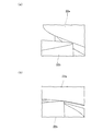
- (A) is the figure which cut
- (b) is the figure which cut
- SP is the screw vacuum pump of embodiment of this invention.
- the screw vacuum pump SP includes a cylindrical casing 1, and a connection pipe (not shown) from a facility (such as a vacuum chamber) to be evacuated is provided on one side (upper side in FIG. 1) of the casing 1.
- a connectable intake port 11 is provided on the other side (lower side in FIG. 1) of the casing 1.
- a discharge port 12 for discharging the gas in the casing 1 to the outside is provided.
- a pair of screw rotors 2 1 and 2 2 is engaged with the helical teeth 22a and 22b formed integrally with the rotary shafts 21a and 21b in a non-contact manner.
- the direction in which the rotation shafts 21 a and 21 b of the pair of screw rotors 2 1 and 2 2 extend is defined as the vertical direction, and the direction perpendicular thereto is defined as the horizontal direction. Shall be used.
- the upper surface opening and the lower surface opening of the casing 1 are closed by an intake side cover 13a and a discharge side cover 13b that hold the working space 1a therein in an airtight manner.
- Bearings 3a and 3b are assembled to the intake side cover 13a and the discharge side cover 13b, respectively, so that the upper and lower ends of the rotating shafts 21a and 21b of the pair of left and right screw rotors 2 1 and 2 2 are supported, respectively. I have to.
- the lower end portions of the rotating shafts 21a and 21b extend to the lower side of the discharge side cover 13b, and gears 4a and 4b having the same shape and meshing with each other are respectively inserted.
- the coupling 5a is provided at the lower end of the right screw rotor 2 1 of the rotary shaft 21a, is coupled to the coupling 5b provided on the drive shaft 61 of a drive motor 6 into the power of the driving motor 6 rotates shaft 21a To be.
- both screw rotors 2 1 and 2 2 rotate in opposite directions in synchronization with each other, and the gas sucked from the intake port 11 of the casing 1 is confined between the screw rotors 2 1 and 2 2 and the casing 1. It is transported, compressed at the end portions of the helical teeth 22a, 22b, and discharged from the discharge port 12.
- the helical teeth 22a and 22b of the screw rotors 2 1 and 2 2 have the same distance (vertical height) between the helical teeth 22a and 22b, that is, the pitch P (or lead) is equal and the twist direction is reverse. Each is formed to become.
- the axial cross-sectional shape and the right-angle cross-sectional shape of the tooth profile of each helical tooth 22a, 22b are the bottom of the tooth (between Ta and Tb in FIG.
- the screw rotors 2 1 and 2 constituting the first arc t1 and the tooth tip portion (between Tc and Td in FIG. 2B), which constitute the rotation axis tc of the rotation shafts 21a and 21b.
- a first curve t3 (between Tb and Tc in FIG. 2B) and a second curve t4 connecting the second arc t2 having the center of rotation tc as the center tc, the first arc t1 and the second arc t2.
- the second curve t4 is formed by combining an outer cycloid curve and an involute curve.
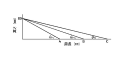
- the length (circumferential length) of the circular arc of the circle is assumed to be A, B, C, for example, and it is considered that this is because the angles ⁇ p1, ⁇ p2, ⁇ p3 formed when these are connected to the pitch height are different. For this reason, the correction
- Equation 3 the distance to be moved from the position where the gap between the tooth surfaces of both the helical teeth 22a and 22b is zero.
- P is the pitch of the helical teeth 22a and 22b
- R is the radial distance from the center of the rotating shafts 21a and 21b
- DG is the half distance between the tooth surfaces of the helical teeth 22a and 22b.
- the correction angle ( ⁇ ) is determined, and the coordinates (X t , Y t ) of the epitrochoid curve when the clearance between the tooth surfaces of both helical teeth 22a, 22b is zero are based on the correction angle ( ⁇ ).
- the correction angle ( ⁇ ) is calculated according to the pitch angle ( ⁇ p) at the distance (R) from the rotation center tc of the screw rotors 2 1 and 2 2 , and the coordinates of the epitrochoid curve are corrected. Therefore, the gap between the tooth surfaces of the helical teeth 22a and 22b when the pair of screw rotors 2 1 and 2 2 mesh with each other in a non-contact manner can be made as small as possible over the entire radial direction.
- the second curve t4 is formed by combining the outer cycloid curve and the involute curve.
- the present invention is not limited to this.
- the second curve t4 is a sine curve, a cycloid curve, or a clothoid curve. There may be. Further, the number of threads of the screw rotors 2 1 and 2 2 may not be 1 but 2 or more.
Landscapes
- Engineering & Computer Science (AREA)
- Mechanical Engineering (AREA)
- General Engineering & Computer Science (AREA)
- Applications Or Details Of Rotary Compressors (AREA)
Abstract
Description





Claims (2)
- ねじれ方向が逆方向で等ピッチの螺旋歯を夫々有する一対のスクリューロータを備え、これら一対のスクリューロータを非接触で互いに噛み合わせた状態でケーシングに格納し、両スクリューロータの同期回転によりケーシングの一端より吸気して他端より吐出するスクリュー真空ポンプであって、
螺旋歯の軸直角断面形状が、その歯底部を構成する、スクリューロータの回転中心を中心とする第1円弧と、その歯先部を構成する、スクリューロータの回転中心を中心とする第2円弧と、第1円弧と第2円弧とを夫々結ぶ第1曲線と第2曲線とで創成されるものにおいて、
スクリューロータの軸直角断面にて互いに直交する径方向の二軸方向をX軸方向及びY軸方向とし、
第1曲線は、両螺旋歯の歯面間の隙間をゼロとした場合の対をなす他方のスクリューロータの第2円弧上の点で創成されるエピトロコイド曲線の径方向における座標(Xt=2Acosθ-rdcos(2θ),Yt=2Asinθ-rdsin(2θ)、Aは両スクリューロータの回転中心間の距離の半分、rdは第2円弧の半径、θは回転角)を、当該座標と次式(数1)で算出される補正角(α)とに基づいて補正し、補正後の各座標(X=Xtcosα-Ytsinα,Y=Xtsinα+Ytcosα)を結んで描くものとしたことを特徴とするスクリュー真空ポンプ。

- 前記第2曲線は、外サイクロイド曲線とインボリュート曲線とを組み合わせて形成されることを特徴とする請求項1記載のスクリュー真空ポンプ。
Priority Applications (3)
| Application Number | Priority Date | Filing Date | Title |
|---|---|---|---|
| CN201580072378.5A CN107110156B (zh) | 2015-01-05 | 2015-12-15 | 螺杆真空泵 |
| JP2016568175A JP6446476B2 (ja) | 2015-01-05 | 2015-12-15 | スクリュー真空ポンプ |
| KR1020177021546A KR101883894B1 (ko) | 2015-01-05 | 2015-12-15 | 스크류 진공 펌프 |
Applications Claiming Priority (2)
| Application Number | Priority Date | Filing Date | Title |
|---|---|---|---|
| JP2015000417 | 2015-01-05 | ||
| JP2015-000417 | 2015-01-13 |
Publications (1)
| Publication Number | Publication Date |
|---|---|
| WO2016110902A1 true WO2016110902A1 (ja) | 2016-07-14 |
Family
ID=56355632
Family Applications (1)
| Application Number | Title | Priority Date | Filing Date |
|---|---|---|---|
| PCT/JP2015/006242 Ceased WO2016110902A1 (ja) | 2015-01-05 | 2015-12-15 | スクリュー真空ポンプ |
Country Status (5)
| Country | Link |
|---|---|
| JP (1) | JP6446476B2 (ja) |
| KR (1) | KR101883894B1 (ja) |
| CN (1) | CN107110156B (ja) |
| TW (1) | TWI670418B (ja) |
| WO (1) | WO2016110902A1 (ja) |
Cited By (6)
| Publication number | Priority date | Publication date | Assignee | Title |
|---|---|---|---|---|
| CN107829931A (zh) * | 2017-11-02 | 2018-03-23 | 西安交通大学 | 一种双螺杆真空泵转子型线 |
| CN107989792A (zh) * | 2018-01-22 | 2018-05-04 | 中国石油大学(华东) | 一种全光滑的螺杆转子 |
| WO2020063375A1 (zh) * | 2018-09-28 | 2020-04-02 | 党祎贤 | 集射真空泵 |
| CN111502999A (zh) * | 2020-05-11 | 2020-08-07 | 台州学院 | 一种干式螺杆真空泵及其螺杆转子 |
| CN113779721A (zh) * | 2021-09-08 | 2021-12-10 | 浙江理工大学 | 一种基于包络面修正的特殊爪型真空泵型线设计方法 |
| CN117212169A (zh) * | 2023-07-28 | 2023-12-12 | 西安交通大学 | 变齿隙双螺杆压缩机转子设计方法、转子及压缩机 |
Families Citing this family (3)
| Publication number | Priority date | Publication date | Assignee | Title |
|---|---|---|---|---|
| CN108050069B (zh) * | 2018-01-22 | 2023-07-25 | 中国石油大学(华东) | 一种低泄漏的全光滑的螺杆转子 |
| GB2607936A (en) * | 2021-06-17 | 2022-12-21 | Edwards Ltd | Screw-type vacuum pump |
| CN114776589B (zh) * | 2022-05-07 | 2025-01-03 | 浙江莱斯特真空装备有限公司 | 真空泵转子及真空泵 |
Citations (6)
| Publication number | Priority date | Publication date | Assignee | Title |
|---|---|---|---|---|
| JPS5491267A (en) * | 1977-12-28 | 1979-07-19 | Oval Eng Co Ltd | Displacementttype flow meter with helical gear |
| JP2003254268A (ja) * | 2002-03-04 | 2003-09-10 | Teijin Seiki Co Ltd | スクリューロータ及びスクリュー機械 |
| WO2005113984A1 (ja) * | 2004-05-24 | 2005-12-01 | Nabtesco Corporation | スクリューロータ及びスクリュー式流体機械 |
| JP2006214366A (ja) * | 2005-02-04 | 2006-08-17 | Hitachi Industrial Equipment Systems Co Ltd | スクリューロータ |
| JP2006266234A (ja) * | 2005-03-25 | 2006-10-05 | Hokuetsu Kogyo Co Ltd | スクリュロータ及びスクリュロータの歯形補正方法 |
| JP2012207660A (ja) * | 2011-03-11 | 2012-10-25 | Toyota Industries Corp | スクリュポンプ |
Family Cites Families (2)
| Publication number | Priority date | Publication date | Assignee | Title |
|---|---|---|---|---|
| DE102008063281A1 (de) * | 2008-12-29 | 2010-07-01 | Oerlikon Leybold Vacuum Gmbh | Vakuumpumpe |
| TW201443341A (zh) * | 2013-05-07 | 2014-11-16 | Univ Nat Pingtung Sci & Tech | 雙螺桿壓縮機 |
-
2015
- 2015-12-15 CN CN201580072378.5A patent/CN107110156B/zh active Active
- 2015-12-15 JP JP2016568175A patent/JP6446476B2/ja active Active
- 2015-12-15 KR KR1020177021546A patent/KR101883894B1/ko active Active
- 2015-12-15 WO PCT/JP2015/006242 patent/WO2016110902A1/ja not_active Ceased
- 2015-12-22 TW TW104143172A patent/TWI670418B/zh active
Patent Citations (6)
| Publication number | Priority date | Publication date | Assignee | Title |
|---|---|---|---|---|
| JPS5491267A (en) * | 1977-12-28 | 1979-07-19 | Oval Eng Co Ltd | Displacementttype flow meter with helical gear |
| JP2003254268A (ja) * | 2002-03-04 | 2003-09-10 | Teijin Seiki Co Ltd | スクリューロータ及びスクリュー機械 |
| WO2005113984A1 (ja) * | 2004-05-24 | 2005-12-01 | Nabtesco Corporation | スクリューロータ及びスクリュー式流体機械 |
| JP2006214366A (ja) * | 2005-02-04 | 2006-08-17 | Hitachi Industrial Equipment Systems Co Ltd | スクリューロータ |
| JP2006266234A (ja) * | 2005-03-25 | 2006-10-05 | Hokuetsu Kogyo Co Ltd | スクリュロータ及びスクリュロータの歯形補正方法 |
| JP2012207660A (ja) * | 2011-03-11 | 2012-10-25 | Toyota Industries Corp | スクリュポンプ |
Cited By (10)
| Publication number | Priority date | Publication date | Assignee | Title |
|---|---|---|---|---|
| CN107829931A (zh) * | 2017-11-02 | 2018-03-23 | 西安交通大学 | 一种双螺杆真空泵转子型线 |
| CN107829931B (zh) * | 2017-11-02 | 2019-02-05 | 西安交通大学 | 一种双螺杆真空泵转子型线 |
| CN107989792A (zh) * | 2018-01-22 | 2018-05-04 | 中国石油大学(华东) | 一种全光滑的螺杆转子 |
| CN107989792B (zh) * | 2018-01-22 | 2023-09-12 | 中国石油大学(华东) | 一种全光滑的螺杆转子 |
| WO2020063375A1 (zh) * | 2018-09-28 | 2020-04-02 | 党祎贤 | 集射真空泵 |
| CN111502999A (zh) * | 2020-05-11 | 2020-08-07 | 台州学院 | 一种干式螺杆真空泵及其螺杆转子 |
| CN111502999B (zh) * | 2020-05-11 | 2022-02-08 | 台州学院 | 一种干式螺杆真空泵及其螺杆转子 |
| CN113779721A (zh) * | 2021-09-08 | 2021-12-10 | 浙江理工大学 | 一种基于包络面修正的特殊爪型真空泵型线设计方法 |
| CN113779721B (zh) * | 2021-09-08 | 2023-11-14 | 浙江理工大学 | 一种基于包络面修正的特殊爪型真空泵型线设计方法 |
| CN117212169A (zh) * | 2023-07-28 | 2023-12-12 | 西安交通大学 | 变齿隙双螺杆压缩机转子设计方法、转子及压缩机 |
Also Published As
| Publication number | Publication date |
|---|---|
| CN107110156B (zh) | 2018-08-24 |
| JPWO2016110902A1 (ja) | 2017-08-10 |
| CN107110156A (zh) | 2017-08-29 |
| KR101883894B1 (ko) | 2018-08-01 |
| JP6446476B2 (ja) | 2018-12-26 |
| TW201634812A (zh) | 2016-10-01 |
| TWI670418B (zh) | 2019-09-01 |
| KR20170102324A (ko) | 2017-09-08 |
Similar Documents
| Publication | Publication Date | Title |
|---|---|---|
| JP6446476B2 (ja) | スクリュー真空ポンプ | |
| US8556607B2 (en) | Screw rotor | |
| CN101627209B (zh) | 油泵转子 | |
| CN116480581B (zh) | 一种螺杆组件及真空泵 | |
| WO2014026440A1 (zh) | 等齿顶宽的单头变螺距螺杆转子 | |
| CN110259682B (zh) | 一种偏心渐开线罗茨转子及其设计方法 | |
| CN107023484A (zh) | 一种不对称的螺杆转子 | |
| JP2002202080A (ja) | シングルスクリュー圧縮機 | |
| CN202926637U (zh) | 一种干式螺杆真空泵转子型线 | |
| JP2005351238A (ja) | スクリューロータ | |
| CN211474421U (zh) | 齿轮泵用转子和齿轮泵 | |
| JP5674044B2 (ja) | 内接歯車ポンプ | |
| JP5561287B2 (ja) | アウターロータの歯形創成方法と内接歯車ポンプ | |
| CN220267947U (zh) | 一种螺杆组件及真空泵 | |
| JP6619987B2 (ja) | スクリューポンプ | |
| CN107829931A (zh) | 一种双螺杆真空泵转子型线 | |
| JP4803442B2 (ja) | オイルポンプロータ | |
| CN114562456A (zh) | 螺杆转子及其组件 | |
| CN114776589A (zh) | 真空泵转子及真空泵 | |
| CN114165440A (zh) | 一种多头双边对称圆弧变螺距螺杆 | |
| CN216477847U (zh) | 罗茨转子及罗茨真空泵 | |
| KR20160109534A (ko) | 스크류 로터를 가지는 건식진공펌프 | |
| JP2008215346A (ja) | ルーツ式ポンプ | |
| WO2013057761A1 (ja) | スクリューポンプ、及びスクリューポンプ用ロータ | |
| JP6077373B2 (ja) | 内接歯車ポンプ |
Legal Events
| Date | Code | Title | Description |
|---|---|---|---|
| 121 | Ep: the epo has been informed by wipo that ep was designated in this application |
Ref document number: 15876782 Country of ref document: EP Kind code of ref document: A1 |
|
| ENP | Entry into the national phase |
Ref document number: 2016568175 Country of ref document: JP Kind code of ref document: A |
|
| NENP | Non-entry into the national phase |
Ref country code: DE |
|
| ENP | Entry into the national phase |
Ref document number: 20177021546 Country of ref document: KR Kind code of ref document: A |
|
| 122 | Ep: pct application non-entry in european phase |
Ref document number: 15876782 Country of ref document: EP Kind code of ref document: A1 |