WO2016104786A1 - 変倍光学系、光学装置、変倍光学系の製造方法 - Google Patents
変倍光学系、光学装置、変倍光学系の製造方法 Download PDFInfo
- Publication number
- WO2016104786A1 WO2016104786A1 PCT/JP2015/086410 JP2015086410W WO2016104786A1 WO 2016104786 A1 WO2016104786 A1 WO 2016104786A1 JP 2015086410 W JP2015086410 W JP 2015086410W WO 2016104786 A1 WO2016104786 A1 WO 2016104786A1
- Authority
- WO
- WIPO (PCT)
- Prior art keywords
- lens group
- lens
- group
- refractive power
- optical system
- Prior art date
- Legal status (The legal status is an assumption and is not a legal conclusion. Google has not performed a legal analysis and makes no representation as to the accuracy of the status listed.)
- Ceased
Links
Images


Classifications
-
- G—PHYSICS
- G02—OPTICS
- G02B—OPTICAL ELEMENTS, SYSTEMS OR APPARATUS
- G02B15/00—Optical objectives with means for varying the magnification
- G02B15/14—Optical objectives with means for varying the magnification by axial movement of one or more lenses or groups of lenses relative to the image plane for continuously varying the equivalent focal length of the objective
- G02B15/16—Optical objectives with means for varying the magnification by axial movement of one or more lenses or groups of lenses relative to the image plane for continuously varying the equivalent focal length of the objective with interdependent non-linearly related movements between one lens or lens group, and another lens or lens group
- G02B15/20—Optical objectives with means for varying the magnification by axial movement of one or more lenses or groups of lenses relative to the image plane for continuously varying the equivalent focal length of the objective with interdependent non-linearly related movements between one lens or lens group, and another lens or lens group having an additional movable lens or lens group for varying the objective focal length
-
- G—PHYSICS
- G02—OPTICS
- G02B—OPTICAL ELEMENTS, SYSTEMS OR APPARATUS
- G02B15/00—Optical objectives with means for varying the magnification
- G02B15/14—Optical objectives with means for varying the magnification by axial movement of one or more lenses or groups of lenses relative to the image plane for continuously varying the equivalent focal length of the objective
- G02B15/144—Optical objectives with means for varying the magnification by axial movement of one or more lenses or groups of lenses relative to the image plane for continuously varying the equivalent focal length of the objective having four groups only
- G02B15/1441—Optical objectives with means for varying the magnification by axial movement of one or more lenses or groups of lenses relative to the image plane for continuously varying the equivalent focal length of the objective having four groups only the first group being positive
- G02B15/144113—Optical objectives with means for varying the magnification by axial movement of one or more lenses or groups of lenses relative to the image plane for continuously varying the equivalent focal length of the objective having four groups only the first group being positive arranged +-++
Definitions
- the present invention relates to a variable magnification optical system, an optical apparatus, and a method for manufacturing the variable magnification optical system.
- variable power optical system as described above has a problem that it cannot achieve good optical performance.
- a variable magnification optical system has a first lens group having a positive refractive power disposed closest to the object side, and a negative refractive power disposed on the image side from the first lens group.
- the distance between the lens arranged at the position facing the object side of the focal group changes, the distance between the lens arranged at the position facing the image side of the focused group and the focusing group changes, and
- the focusing group is composed of one single lens having a positive refractive power, and satisfies the following conditional expression. 1.00 ⁇ ff / ( ⁇ fn) ⁇ 2.30
- ff focal length of the focusing group
- fn focal length of the negative lens group
- a variable magnification optical system includes a first lens group having a positive refractive power arranged closest to the object side, and a negative refractive power arranged on the image side from the first lens group.
- a focusing group disposed between the first lens group and the positive lens group, and the distance between the first lens group and the negative lens group changes during zooming, and the negative lens group and the positive lens group
- the distance between the focusing group and the lens arranged at the position facing the object side of the focusing group changes during focusing, and the focusing side and the image side of the focusing group change
- the distance between the lens and the lens disposed at a position facing the lens changes, and the focusing group is formed by a single lens having a positive refractive power
- Another aspect of the present invention is: In order from the object side, a first lens group having a positive refractive power, a second lens group having a negative refractive power, a third lens group having a positive refractive power, and a fourth lens having a positive refractive power And having a group During zooming, the distance between the lens groups changes,
- the third lens group comprises one single lens having positive refractive power;
- a variable magnification optical system that satisfies the following conditional expression is provided. 1.00 ⁇ ff / ( ⁇ fn) ⁇ 2.30
- fn focal length of the second lens group
- ff focal length of the third lens group
- Another aspect of the present invention provides an optical device having the zooming optical system.
- Another embodiment of the present invention is as follows.
- a first lens group having a positive refractive power, a second lens group having a negative refractive power, a third lens group having a positive refractive power, and a fourth lens having a positive refractive power A variable magnification optical system having a group,
- the third lens group is composed of one single lens having a positive refractive power;
- the zoom optical system satisfies the following conditional expression, Provided is a method for manufacturing a variable magnification optical system in which the distance between the lens groups changes at the time of variable magnification. 1.00 ⁇ ff / ( ⁇ fn) ⁇ 2.30
- fn focal length of the second lens group
- ff focal length of the third lens group
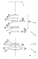
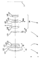
- FIG. 1 is a cross-sectional view showing a lens configuration of a variable magnification optical system according to the first example.
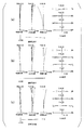
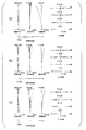
- 2 (a), 2 (b) and 2 (c) are respectively when an object at infinity is in focus in the wide-angle end state, the intermediate focal length state and the telephoto end state of the variable magnification optical system according to the first example.
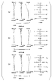
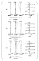
- FIG. 3 (a), 3 (b) and 3 (c) are respectively when focusing on a short-distance object in the wide-angle end state, intermediate focal length state and telephoto end state of the variable magnification optical system according to the first example.
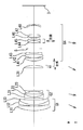
- FIG. FIG. 4 is a cross-sectional view showing the lens configuration of the variable magnification optical system according to the second example.
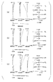
- FIG. 5 (a), 5 (b) and 5 (c) are respectively when an object at infinity is in focus in the wide-angle end state, the intermediate focal length state and the telephoto end state of the variable magnification optical system according to the second example.
- FIG. 6 (a), 6 (b) and 6 (c) are respectively when a short distance object is focused in the wide-angle end state, intermediate focal length state and telephoto end state of the variable magnification optical system according to the second example.
- FIG. FIG. 7 is a cross-sectional view showing a lens configuration of a variable magnification optical system according to the third example.
- FIGS. 9A, 9B, and 9C are diagrams for focusing a short distance object in the wide-angle end state, the intermediate focal length state, and the telephoto end state of the variable magnification optical system according to the third example, respectively.
- FIG. FIG. 10 is a cross-sectional view showing a lens configuration of a variable magnification optical system according to the fourth example.
- FIG. 11 (a), 11 (b), and 11 (c), respectively, are focused on an object at infinity in the wide-angle end state, the intermediate focal length state, and the telephoto end state of the variable magnification optical system according to the fourth example.
- FIG. 12 (a), 12 (b), and 12 (c), respectively, are those when focusing on a short-distance object in the wide-angle end state, intermediate focal length state, and telephoto end state of the variable magnification optical system according to the fourth example.
- FIG. FIG. 13 is a diagram showing a configuration of an example of a camera provided with a variable magnification optical system.
- FIG. 14 is a diagram showing an outline of an example of a method for manufacturing a variable magnification optical system.
- variable magnification optical system an optical apparatus, and a method for manufacturing the variable magnification optical system will be described.
- variable magnification optical system includes a first lens group having a positive refractive power disposed closest to the object side, and a negative lens having a negative refractive power disposed closer to the image side than the first lens group.
- the group consists of a single lens having positive refractive power.
- a first lens group having a positive refractive power disposed closest to the object side a negative lens group having a negative refractive power disposed closer to the image side than the first lens group, and Having a vibration-proof group movable so as to include a component in a direction orthogonal to the optical axis, and disposed between a positive lens group having positive refractive power and the negative lens group and the positive lens group A focusing group, and at the time of zooming, the distance between the first lens group and the negative lens group changes, the distance between the negative lens group and the positive lens group changes, and in focusing, The distance between the focusing group and the lens arranged at the position facing the object side of the focusing group changes, and the lens arranged at the position facing the focusing group and the image side of the focusing group;
- the focusing group is composed of one single lens having a positive refractive power.
- the zoom optical system includes, in order from the object side, a first lens group having a positive refractive power, a second lens group having a negative refractive power, and a third lens having a positive refractive power.
- a lens group and a fourth lens group having a positive refractive power, and at the time of zooming, the distance between the lens groups changes, and the third lens group is a single lens having a positive refractive power. It consists of a lens.
- variable magnification optical system satisfies the following conditional expression (1).
- (1) 1.00 ⁇ ff / ( ⁇ fn) ⁇ 2.30
- fn focal length of the negative lens group (second lens group)
- ff focal length of the focusing group (third lens group)
- Conditional expression (1) defines the ratio between the focal length of the negative lens group (second lens group) and the focal length of the focusing group (third lens group).
- conditional expression (1) when the corresponding value of conditional expression (1) is below the lower limit value, the refractive power of the focusing group (third lens group) increases. This is not preferable because it becomes difficult to correct spherical aberration and coma in the telephoto end state.
- the lower limit value of conditional expression (1) is 1.40. In order to further secure the effect, it is preferable that the lower limit value of conditional expression (1) is 1.61.
- the refractive power of the negative lens group increases. This is not preferable because correction of coma and astigmatism becomes difficult in the wide-angle end state.
- the upper limit value of conditional expression (1) is 2.20. In order to make the effect more reliable, it is preferable that the upper limit value of the conditional expression (1) is 2.16.
- variable magnification optical system with good optical performance can be realized.
- the aberration fluctuation is large when focusing on a short distance object.
- the conventional variable magnification optical system is configured to extend the first lens group having a large weight when focusing on a short-distance object, the load on the autofocus mechanism such as a motor is large.
- the variable magnification optical system can suppress aberration fluctuations when focusing on a short-distance object.
- the variable magnification optical system adopts an inner focus method and performs focusing with a small and lightweight lens, so that the burden on the autofocus mechanism is small.
- variable magnification optical system can focus from an object at infinity to an object at a short distance by moving the third lens group along the optical axis. With this configuration, it is possible to satisfactorily correct aberration fluctuations during focusing.
- the zoom optical system includes, in order from the object side, a first lens group having a positive refractive power and a second lens group having a negative refractive power. It is preferable that the distance between the first lens group and the second lens group changes and the following conditional expression (2) is satisfied. (2) 2.00 ⁇ f1 / ( ⁇ fn) ⁇ 4.00 However, f1: Focal length of the first lens group fn: Focal length of the second lens group
- Conditional expression (2) defines the ratio between the focal length of the first lens group and the focal length of the second lens group.
- variable magnification optical system when the corresponding value of the conditional expression (2) is lower than the lower limit value, the refractive power of the first lens unit is increased. This is not preferable because it becomes difficult to correct spherical aberration and longitudinal chromatic aberration in the telephoto end state.
- the lower limit value of conditional expression (2) is 2.50.
- the lower limit value of the conditional expression (2) is 2.85.
- conditional expression (2) when the corresponding value of the conditional expression (2) exceeds the upper limit value, the refractive power of the second lens group increases. This is not preferable because correction of coma and astigmatism becomes difficult in the wide-angle end state.
- the upper limit value of conditional expression (2) is 3.70. In order to make the effect more reliable, it is preferable that the upper limit value of conditional expression (2) is 3.63.
- variable magnification optical system includes, in order from the object side, a first lens group having a positive refractive power, a second lens group having a negative refractive power, and a third lens having a positive refractive power. And a fourth lens group having a positive refractive power, and the distance between the first lens group and the second lens group changes during zooming, and the second lens group and the third lens The distance between the third lens group and the fourth lens group changes, and at least a part of the fourth lens group moves so as to include a component in a direction orthogonal to the optical axis. It is preferably possible. As a result, image blur due to camera shake, vibration, or the like can be corrected, that is, image stabilization can be achieved, and in particular, excellent optical performance can be achieved even during image stabilization while reducing the size of the lens barrel.
- variable magnification optical system includes, in order from the object side, a first lens group having a positive refractive power, a second lens group having a negative refractive power, and a third lens having a positive refractive power. And a fourth lens group having a positive refractive power, and the distance between the first lens group and the second lens group changes during zooming, and the second lens group and the third lens It is preferable that the distance between the groups changes, the distance between the third lens group and the fourth lens group changes, and the following conditional expression (3) is satisfied.
- (3) 0.10 ⁇ ff / fp ⁇ 0.90
- ff focal length of the third lens group
- fp focal length of the fourth lens group
- Conditional expression (3) defines the ratio between the focal length of the third lens group and the focal length of the fourth lens group.
- the variable magnification optical system can satisfactorily correct spherical aberration, coma and astigmatism in the telephoto end state by satisfying conditional expression (3).
- conditional expression (3) when the corresponding value of conditional expression (3) is below the lower limit, the refractive power of the third lens unit increases. This is not preferable because it becomes difficult to correct spherical aberration and coma in the telephoto end state.
- the lower limit value of conditional expression (3) is 0.20. In order to further secure the effect, it is preferable that the lower limit value of conditional expression (3) is 0.24.
- variable magnification optical system when the corresponding value of the conditional expression (3) exceeds the upper limit value, the refractive power of the fourth lens group increases. This is not preferable because correction of coma and astigmatism becomes difficult in the telephoto end state.
- variable magnification optical system includes, in order from the object side, a first lens group having a positive refractive power, a second lens group having a negative refractive power, and a third lens having a positive refractive power. And the distance between the first lens group and the second lens group changes, the distance between the second lens group and the third lens group changes, and the following conditions are satisfied: It is preferably possible to satisfy equation (4). (4) 60.00 ⁇ d3 However, ⁇ d3: Abbe number of a single lens included in the third lens group
- Conditional expression (4) defines the Abbe number of a single lens in the third lens group.
- conditional expression (4) In a variable magnification optical system, if the corresponding value of conditional expression (4) is less than the lower limit, it is not preferable because it is difficult to correct longitudinal chromatic aberration and spherical aberration in the telephoto end state. In order to secure the effect, it is preferable to set the lower limit value of conditional expression (4) to 63.00. In order to make the effect more reliable, it is preferable that the lower limit value of conditional expression (4) is 64.00.
- the optical device includes a variable magnification optical system having the above-described configuration. Thereby, an optical device having good optical performance can be realized.
- the zoom optical system manufacturing method includes, in order from the object side, a first lens group having a positive refractive power, a second lens group having a negative refractive power, and a first lens group having a positive refractive power.
- a variable magnification optical system manufacturing method having three lens groups and a fourth lens group having a positive refractive power, wherein the third lens group is composed of one single lens having a positive refractive power.
- the zoom optical system satisfies the following conditional expression (1) so that the distance between the lens groups changes during zooming. Thereby, a variable magnification optical system having good optical performance can be manufactured.
- (1) 1.00 ⁇ ff / ( ⁇ fn) ⁇ 2.30
- fn focal length of the second lens group
- ff focal length of the third lens group
- FIG. 1 is a cross-sectional view of the variable magnification optical system according to the first example in the wide-angle end state. 1 and FIG. 4, FIG. 7 and FIG. 10, which will be described later, indicate the movement trajectory of each lens group during zooming from the wide-angle end state (W) to the telephoto end state (T).
- variable magnification optical system includes, in order from the object side, a first lens group G1 having a positive refractive power, a second lens group G2 having a negative refractive power, and a third lens having a positive refractive power.
- the lens group G3 includes a fourth lens group G4 having a positive refractive power.
- the first lens group G1 includes, in order from the object side, a positive meniscus lens L11 having a convex surface facing the object side, and a cemented lens of a negative meniscus lens L12 having a convex surface facing the object side and a biconvex positive lens L13.
- the second lens group G2 includes, in order from the object side, a cemented lens of a biconcave negative lens L21 and a positive meniscus lens L22 having a convex surface facing the object side, and a biconcave negative lens L23.
- the third lens group G3 is composed of a biconvex positive lens L31.
- the fourth lens group G4 includes, in order from the object side, an aperture stop S, a cemented lens of a biconvex positive lens L41, a negative meniscus lens L42 having a convex surface on the image side, and a positive surface having a convex surface on the image side. It consists of a cemented lens of a meniscus lens L43 and a biconcave negative lens L44, a biconvex positive lens L45, and a negative meniscus lens L46 with a convex surface facing the image side.
- the air gap between the first lens group G1 and the second lens group G2 and the second lens group at the time of zooming from the wide-angle end state to the telephoto end state is arranged along the optical axis so that the air gap between G2 and the third lens group G3 and the air gap between the third lens group G3 and the fourth lens group G4 are changed. Move each.
- the third lens group G3 is moved to the image side along the optical axis, thereby focusing from an object at infinity to an object at a short distance.
- the image stabilization is achieved by moving the cemented lens of the positive meniscus lens L43 and the negative lens L44 in the fourth lens group G4 so as to include a component in a direction orthogonal to the optical axis. I do.
- Table 1 below lists values of specifications of the variable magnification optical system according to the present example.
- f represents the focal length
- Bf represents the back focus (distance on the optical axis between the lens surface closest to the image side and the image plane I).
- the surface number is the order of the optical surfaces counted from the object side
- r is the radius of curvature
- d is the surface interval (the interval between the nth surface (n is an integer) and the n + 1th surface)
- nd is The refractive index for d-line (wavelength 587.6 nm) and ⁇ d indicate the Abbe number for d-line (wavelength 587.6 nm), respectively.
- the object plane indicates the object plane
- the variable indicates the variable plane spacing
- the stop S indicates the aperture stop S
- the image plane indicates the image plane I.
- the radius of curvature r ⁇ indicates a plane.
- FNO is the F number
- ⁇ is the half angle of view (unit is “°”)
- Y is the image height
- TL is the total length of the variable magnification optical system according to the present embodiment (from the first surface to the image surface I).
- Dn represents the variable distance between the nth surface and the (n + 1) th surface.
- W represents the wide-angle end state
- M represents the intermediate focal length state
- T represents the telephoto end state.
- d0 represents the distance from the object to the first surface.
- [Lens Group Data] indicates the start surface and focal length of each lens group.
- [Conditional Expression Corresponding Value] shows the corresponding value of each conditional expression of the variable magnification optical system according to the present example.
- the focal length f, the radius of curvature r, and other length units listed in Table 1 are generally “mm”.
- the optical system is not limited to this because an equivalent optical performance can be obtained even when proportionally enlarged or proportionally reduced.
- symbol of Table 1 described above shall be similarly used also in the table
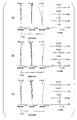
- FIG. 2 (a), 2 (b) and 2 (c) are respectively when an object at infinity is in focus in the wide-angle end state, the intermediate focal length state and the telephoto end state of the variable magnification optical system according to the first example.
- FIG. 3 (a), 3 (b) and 3 (c) are respectively when focusing on a short-distance object in the wide-angle end state, intermediate focal length state and telephoto end state of the variable magnification optical system according to the first example.
- FNO represents the F number
- Y represents the image height
- NA represents the numerical aperture
- the spherical aberration diagram shows the value of the F number FNO or the numerical aperture NA corresponding to the maximum aperture
- the astigmatism diagram and the distortion diagram show the maximum value of the image height Y
- the coma aberration diagram shows each image height. Indicates the value of.
- d indicates the aberration at the d-line (wavelength 587.6 nm)
- g indicates the aberration at the g-line (wavelength 435.8 nm).
- the solid line indicates the sagittal image plane
- the broken line indicates the meridional image plane.
- the coma aberration diagram shows coma aberration at each image height Y. Note that the same reference numerals as in this embodiment are used in the aberration diagrams of each embodiment described later.
- variable magnification optical system according to this example has various aberrations corrected satisfactorily and has excellent imaging performance.
- FIG. 4 is a sectional view of the variable magnification optical system according to the second example in the wide-angle end state.
- the variable magnification optical system according to the present example includes, in order from the object side, a first lens group G1 having a positive refractive power, a second lens group G2 having a negative refractive power, and a third lens having a positive refractive power.
- the lens group G3 includes a fourth lens group G4 having a positive refractive power.
- the first lens group G1 includes, in order from the object side, a cemented lens of a negative meniscus lens L11 having a convex surface directed toward the object side and a biconvex positive lens L12.
- the second lens group G2 includes, in order from the object side, a cemented lens of a biconvex positive lens L21 and a biconcave negative lens L22, and a biconcave negative lens L23.
- the third lens group G3 is composed of a biconvex positive lens L31.
- the fourth lens group G4 includes, in order from the object side, an aperture stop S, a cemented lens of a biconvex positive lens L41, a negative meniscus lens L42 having a convex surface on the image side, and a positive surface having a convex surface on the image side. It consists of a cemented lens of a meniscus lens L43 and a biconcave negative lens L44, a biconvex positive lens L45, and a negative meniscus lens L46 with a convex surface facing the image side.
- the air gap between the first lens group G1 and the second lens group G2 and the second lens group at the time of zooming from the wide-angle end state to the telephoto end state is arranged along the optical axis so that the air gap between G2 and the third lens group G3 and the air gap between the third lens group G3 and the fourth lens group G4 are changed. Move each.
- the third lens group G3 is moved to the image side along the optical axis, thereby focusing from an object at infinity to an object at a short distance.
- the image stabilization is achieved by moving the cemented lens of the positive meniscus lens L43 and the negative lens L44 in the fourth lens group G4 so as to include a component in a direction orthogonal to the optical axis. I do.
- Table 2 below provides values of specifications of the variable magnification optical system according to the present example.
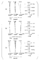
- FIG. 5 (a), 5 (b) and 5 (c) are respectively when an object at infinity is in focus in the wide-angle end state, the intermediate focal length state and the telephoto end state of the variable magnification optical system according to the second example.
- FIG. 6 (a), 6 (b) and 6 (c) are respectively when a short distance object is focused in the wide-angle end state, intermediate focal length state and telephoto end state of the variable magnification optical system according to the second example.
- variable magnification optical system according to the present example has various aberrations corrected satisfactorily and has excellent imaging performance.
- FIG. 7 is a cross-sectional view of the zoom optical system according to the third example in the wide-angle end state.
- the variable magnification optical system according to the present example includes, in order from the object side, a first lens group G1 having a positive refractive power, a second lens group G2 having a negative refractive power, and a third lens having a positive refractive power.
- the lens group G3 includes a fourth lens group G4 having a positive refractive power.
- the first lens group G1 includes, in order from the object side, a cemented lens of a negative meniscus lens L11 having a convex surface directed toward the object side and a biconvex positive lens L12.
- the second lens group G2 includes, in order from the object side, a cemented lens of a biconcave negative lens L21 and a positive meniscus lens L22 having a convex surface facing the object side, and a biconcave negative lens L23.
- the third lens group G3 is composed of a biconvex positive lens L31.
- the fourth lens group G4 includes, in order from the object side, a cemented lens of a biconvex positive lens L41 and a biconcave negative lens L42, an aperture stop S, and a positive meniscus lens L43 with a convex surface facing the image side. It consists of a cemented lens with a biconcave negative lens L44, a biconvex positive lens L45, a biconvex positive lens L46, and a biconcave negative lens L47.
- the air gap between the first lens group G1 and the second lens group G2 and the second lens group at the time of zooming from the wide-angle end state to the telephoto end state is arranged along the optical axis so that the air gap between G2 and the third lens group G3 and the air gap between the third lens group G3 and the fourth lens group G4 are changed. Move each.
- the third lens group G3 is moved to the image side along the optical axis, thereby focusing from an object at infinity to an object at a short distance.
- the image stabilization is achieved by moving the cemented lens of the positive meniscus lens L43 and the negative lens L44 in the fourth lens group G4 so as to include a component in a direction orthogonal to the optical axis. I do. Table 3 below lists values of specifications of the variable magnification optical system according to the present example.
- FIGS. 8A, 8B, and 8C are respectively focused on an object at infinity in the wide-angle end state, the intermediate focal length state, and the telephoto end state of the variable magnification optical system according to the third example.
- FIGS. 9A, 9B, and 9C are diagrams for focusing a short distance object in the wide-angle end state, the intermediate focal length state, and the telephoto end state of the variable magnification optical system according to the third example, respectively.
- FIG. 9A, 9B, and 9C are diagrams for focusing a short distance object in the wide-angle end state, the intermediate focal length state, and the telephoto end state of the variable magnification optical system according to the third example, respectively.
- variable magnification optical system according to the present example has various aberrations corrected satisfactorily and has excellent imaging performance.
- FIG. 10 is a sectional view of the zoom optical system according to the fourth example in the wide-angle end state.
- the variable magnification optical system according to the present example includes, in order from the object side, a first lens group G1 having a positive refractive power, a second lens group G2 having a negative refractive power, and a third lens having a positive refractive power.
- the lens group G3 includes a fourth lens group G4 having a positive refractive power.
- the first lens group G1 includes, in order from the object side, a positive meniscus lens L11 having a convex surface facing the object side, a negative meniscus lens L12 having a convex surface facing the object side, and a positive meniscus lens L13 having a convex surface facing the object side. It consists of a cemented lens.
- the second lens group G2 includes, in order from the object side, a cemented lens of a biconcave negative lens L21 and a positive meniscus lens L22 having a convex surface facing the object side, and a biconcave negative lens L23.
- the third lens group G3 is composed of a biconvex positive lens L31.
- the fourth lens group G4 includes, in order from the object side, a positive meniscus lens L41 having a convex surface directed toward the object side, a cemented lens of a biconvex positive lens L42 and a biconcave negative lens L43, an aperture stop S, A cemented lens of a positive meniscus lens L44 having a convex surface facing the image side and a biconcave negative lens L45, and a cemented lens of a negative meniscus lens L46 having a convex surface facing the object side and a biconvex positive lens L47; And a negative meniscus lens L48 having a convex surface directed toward the object side.
- the air gap between the first lens group G1 and the second lens group G2 and the second lens group at the time of zooming from the wide-angle end state to the telephoto end state is arranged along the optical axis so that the air gap between G2 and the third lens group G3 and the air gap between the third lens group G3 and the fourth lens group G4 are changed. Move each.
- the third lens group G3 is moved to the image side along the optical axis, thereby focusing from an object at infinity to an object at a short distance.
- the image stabilization is achieved by moving the cemented lens of the positive meniscus lens L44 and the negative lens L45 in the fourth lens group G4 so as to include a component in a direction perpendicular to the optical axis. I do. Table 4 below lists values of specifications of the variable magnification optical system according to the present example.
- FIG. 11 (a), 11 (b), and 11 (c), respectively, are focused on an object at infinity in the wide-angle end state, the intermediate focal length state, and the telephoto end state of the variable magnification optical system according to the fourth example.
- FIG. 12 (a), 12 (b), and 12 (c), respectively, are those when focusing on a short-distance object in the wide-angle end state, intermediate focal length state, and telephoto end state of the variable magnification optical system according to the fourth example.
- FIG. 12 (a), 12 (b), and 12 (c), respectively, are those when focusing on a short-distance object in the wide-angle end state, intermediate focal length state, and telephoto end state of the variable magnification optical system according to the fourth example.
- variable magnification optical system according to the present example has various aberrations corrected satisfactorily and has excellent imaging performance.
- each of the above embodiments it is possible to realize a variable magnification optical system having a good optical performance while having an anti-vibration function.
- each said Example has shown one specific example of this invention, and this invention is not limited to these. The following contents can be appropriately adopted as long as the optical performance of the variable magnification optical system is not impaired.
- variable magnification optical system Although a four-group configuration is shown as a numerical example of the variable magnification optical system, the present application is not limited to this, and a variable magnification optical system of another group configuration (for example, five groups) can also be configured. Specifically, a configuration in which a lens or a lens group is added on the most object side or the most image side of the zoom optical system may be used.
- the variable magnification optical system uses the third lens group consisting of one positive single lens as the focusing group (focusing lens group) on the optical axis in order to focus from an object at infinity to an object at a short distance. It is the structure moved along.
- the above focusing group can also be applied to autofocus, and is also suitable for driving by an autofocus motor, such as an ultrasonic motor.
- any lens group or a part thereof is moved as a vibration-proof lens group so as to include a component in a direction perpendicular to the optical axis, or an in-plane direction including the optical axis It can also be set as the structure which carries out anti-vibration by carrying out rotational movement (oscillation) to (F).
- the lens surface of the lens constituting the variable magnification optical system may be a spherical surface, a flat surface, or an aspherical surface.
- the lens surface is a spherical surface or a flat surface, lens processing and assembly adjustment are facilitated, and deterioration of optical performance due to errors in lens processing and assembly adjustment can be prevented. Further, even when the image plane is deviated, there is little deterioration in drawing performance.
- the lens surface is aspherical, any of aspherical surface by grinding, glass mold aspherical surface in which glass is molded into an aspherical shape, or composite aspherical surface in which resin provided on the glass surface is formed in an aspherical shape Good.
- the lens surface may be a diffractive surface, and the lens may be a gradient index lens (GRIN lens) or a plastic lens.
- GRIN lens gradient index lens
- the aperture stop be disposed in the fourth lens group, and the role may be substituted by a lens frame without providing a member as the aperture stop. Further, an antireflection film having a high transmittance in a wide wavelength region may be provided on the lens surface of the lens constituting the variable magnification optical system. Thereby, flare and ghost can be reduced, and high optical performance with high contrast can be achieved.
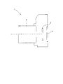
- FIG. 13 is a diagram illustrating a configuration of an example of a camera including a variable magnification optical system.
- the camera 1 is a so-called mirrorless camera of an interchangeable lens type that includes the variable magnification optical system according to the first example as the photographing lens 2.
- the camera 1 In the camera 1, light from an object (not shown) that is not shown is collected by the taking lens 2, and passes through an OLPF (Optical Low Pass Filter) that is not shown on the imaging surface of the imaging unit 3. Form a subject image. Then, the subject image is photoelectrically converted by the photoelectric conversion element provided in the imaging unit 3 to generate an image of the subject. This image is displayed on an EVF (Electronic view finder) 4 provided in the camera 1. Thus, the photographer can observe the subject via the EVF 4. When the release button (not shown) is pressed by the photographer, the subject image generated by the imaging unit 3 is stored in a memory (not shown). In this way, the photographer can shoot the subject with the camera 1.
- OLPF Optical Low Pass Filter
- variable magnification optical system according to the first embodiment mounted on the camera 1 as the photographing lens 2 has good optical performance. That is, the camera 1 can realize good optical performance. Even if a camera equipped with the variable magnification optical system according to the second to fourth embodiments as the photographing lens 2 is configured, the same effect as the camera 1 can be obtained. Further, even when the variable magnification optical system according to each of the above embodiments is mounted on a single-lens reflex camera that has a quick return mirror and observes a subject with a finder optical system, the same effect as the camera 1 can be obtained. it can.
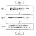
- FIG. 14 is a diagram showing an outline of a manufacturing method of the variable magnification optical system.
- the zoom optical system manufacturing method shown in FIG. 14 includes, in order from the object side, a first lens group having a positive refractive power, a second lens group having a negative refractive power, and a third lens having a positive refractive power.
- a method for manufacturing a variable magnification optical system having a lens group and a fourth lens group having a positive refractive power includes the following steps S1 to S3.
- Step S1 First to fourth lens groups are prepared, and the third lens group is made of one single lens having a positive refractive power. Then, each lens group is arranged in the lens barrel in order from the object side.
- Step S2 The variable magnification optical system is made to satisfy the following conditional expression (1).
- (1) 1.00 ⁇ ff / ( ⁇ fn) ⁇ 2.30
- fn focal length of the second lens group
- ff focal length of the third lens group
- Step S3 A known moving mechanism is provided in the lens barrel so that the distance between the lens groups changes during zooming.
- variable magnification optical system having good optical performance can be manufactured.
- G1 First lens group G2 Second lens group (negative lens group) G3 Third lens group (focusing group) G4 4th lens group (positive lens group) S aperture stop I image plane W wide-angle end state T telephoto end state
Landscapes
- Physics & Mathematics (AREA)
- General Physics & Mathematics (AREA)
- Optics & Photonics (AREA)
- Nonlinear Science (AREA)
- Lenses (AREA)
Abstract
変倍光学系は、最も物体側に配置された正の屈折力を有する第1レンズ群(G1)と、第1レンズ群より像側に配置された負の屈折力を有する負レンズ群(G2)と、負レンズ群より像側に配置され、正の屈折力を有する正レンズ群(G4)と、負レンズ群と正レンズ群との間に配置された合焦(G3)群と、を有し、変倍時に、第1レンズ群と負レンズ群との間隔が変化し、負レンズ群と正レンズ群との間隔が変化し、合焦に際し、合焦群と合焦群の物体側に対向する位置に配置されたレンズとの間隔が変化し、合焦群と合焦群の像側に対向する位置に配置されたレンズとの間隔が変化し、合焦群が、正の屈折力を有する1枚の単レンズ(L31)からなり、所定の条件式を満足する。
Description
本発明は、変倍光学系、光学装置、変倍光学系の製造方法に関する。
本願は、2014年12月26日に出願された日本国特許出願2014-266037号に基づき優先権を主張し、その内容をここに援用する。
本願は、2014年12月26日に出願された日本国特許出願2014-266037号に基づき優先権を主張し、その内容をここに援用する。
従来、写真用カメラ、電子スチルカメラ、ビデオカメラ等に適した変倍光学系が提案されている(例えば、特許文献1を参照。)。
しかしながら、上述のような従来の変倍光学系は、良好な光学性能を達成できていないという問題があった。
本発明の一態様に係る変倍光学系は、最も物体側に配置された正の屈折力を有する第1レンズ群と、前記第1レンズ群より像側に配置された負の屈折力を有する負レンズ群と、前記負レンズ群より像側に配置され、正の屈折力を有する正レンズ群と、前記負レンズ群と前記正レンズ群との間に配置された合焦群と、を有し、変倍時に、前記第1レンズ群と前記負レンズ群との間隔が変化し、前記負レンズ群と前記正レンズ群との間隔が変化し、合焦に際し、前記合焦群と前記合焦群の物体側に対向する位置に配置されたレンズとの間隔が変化し、前記合焦群と前記合焦群の像側に対向する位置に配置されたレンズとの間隔が変化し、前記合焦群が、正の屈折力を有する1枚の単レンズからなり、以下の条件式を満足する。
1.00<ff/(-fn)<2.30
ただし、
ff:前記合焦群の焦点距離
fn:前記負レンズ群の焦点距離
1.00<ff/(-fn)<2.30
ただし、
ff:前記合焦群の焦点距離
fn:前記負レンズ群の焦点距離
本発明の別の一態様に係る変倍光学系は、最も物体側に配置された正の屈折力を有する第1レンズ群と、前記第1レンズ群より像側に配置された負の屈折力を有する負レンズ群と、少なくとも一部に光軸と直交する方向の成分を含むように移動可能な防振群を有し、正の屈折力を有する正レンズ群と、前記負レンズ群と前記正レンズ群との間に配置された合焦群と、を有し、変倍時に、前記第1レンズ群と前記負レンズ群との間隔が変化し、前記負レンズ群と前記正レンズ群との間隔が変化し、合焦に際し、前記合焦群と前記合焦群の物体側に対向する位置に配置されたレンズとの間隔が変化し、前記合焦群と前記合焦群の像側に対向する位置に配置されたレンズとの間隔が変化し、前記合焦群が、正の屈折力を有する1枚の単レンズからなり、以下の条件式を満足する。
1.00<ff/(-fn)<2.30
ただし、
ff:前記合焦群の焦点距離
fn:前記負レンズ群の焦点距離
1.00<ff/(-fn)<2.30
ただし、
ff:前記合焦群の焦点距離
fn:前記負レンズ群の焦点距離
本発明の別の一態様は、
物体側から順に、正の屈折力を有する第1レンズ群と、負の屈折力を有する第2レンズ群と、正の屈折力を有する第3レンズ群と、正の屈折力を有する第4レンズ群とを有し、
変倍時に、前記レンズ群どうしの間隔が変化し、
前記第3レンズ群が、正の屈折力を有する1枚の単レンズからなり、
以下の条件式を満足する変倍光学系を提供する。
1.00<ff/(-fn)<2.30
ただし、
fn:前記第2レンズ群の焦点距離
ff:前記第3レンズ群の焦点距離
物体側から順に、正の屈折力を有する第1レンズ群と、負の屈折力を有する第2レンズ群と、正の屈折力を有する第3レンズ群と、正の屈折力を有する第4レンズ群とを有し、
変倍時に、前記レンズ群どうしの間隔が変化し、
前記第3レンズ群が、正の屈折力を有する1枚の単レンズからなり、
以下の条件式を満足する変倍光学系を提供する。
1.00<ff/(-fn)<2.30
ただし、
fn:前記第2レンズ群の焦点距離
ff:前記第3レンズ群の焦点距離
また本発明の別の一態様は、前記変倍光学系を有する光学装置を提供する。
また本発明の別の一態様は、
物体側から順に、正の屈折力を有する第1レンズ群と、負の屈折力を有する第2レンズ群と、正の屈折力を有する第3レンズ群と、正の屈折力を有する第4レンズ群とを有する変倍光学系の製造方法であって、
前記第3レンズ群が、正の屈折力を有する1枚の単レンズからなるようにし、
前記変倍光学系が以下の条件式を満足するようにし、
変倍時に、前記レンズ群どうしの間隔が変化するようにする変倍光学系の製造方法を提供する。
1.00<ff/(-fn)<2.30
ただし、
fn:前記第2レンズ群の焦点距離
ff:前記第3レンズ群の焦点距離
物体側から順に、正の屈折力を有する第1レンズ群と、負の屈折力を有する第2レンズ群と、正の屈折力を有する第3レンズ群と、正の屈折力を有する第4レンズ群とを有する変倍光学系の製造方法であって、
前記第3レンズ群が、正の屈折力を有する1枚の単レンズからなるようにし、
前記変倍光学系が以下の条件式を満足するようにし、
変倍時に、前記レンズ群どうしの間隔が変化するようにする変倍光学系の製造方法を提供する。
1.00<ff/(-fn)<2.30
ただし、
fn:前記第2レンズ群の焦点距離
ff:前記第3レンズ群の焦点距離
以下、変倍光学系、光学装置及び変倍光学系の製造方法について説明する。
一実施形態において、変倍光学系は、最も物体側に配置された正の屈折力を有する第1レンズ群と、前記第1レンズ群より像側に配置された負の屈折力を有する負レンズ群と、前記負レンズ群より像側に配置され、正の屈折力を有する正レンズ群と、前記負レンズ群と前記正レンズ群との間に配置された合焦群と、を有し、変倍時に、前記第1レンズ群と前記負レンズ群との間隔が変化し、前記負レンズ群と前記正レンズ群との間隔が変化し、合焦に際し、前記合焦群と前記合焦群の物体側に対向する位置に配置されたレンズとの間隔が変化し、前記合焦群と前記合焦群の像側に対向する位置に配置されたレンズとの間隔が変化し、前記合焦群が、正の屈折力を有する1枚の単レンズからなる。この構成により、鏡筒の小型化を図りつつ、変倍時の収差変動を良好に補正することができる。また、合焦時の収差変動を良好に補正することができる。
代替実施形態において、最も物体側に配置された正の屈折力を有する第1レンズ群と、前記第1レンズ群より像側に配置された負の屈折力を有する負レンズ群と、少なくとも一部に光軸と直交する方向の成分を含むように移動可能な防振群を有し、正の屈折力を有する正レンズ群と、前記負レンズ群と前記正レンズ群との間に配置された合焦群と、を有し、変倍時に、前記第1レンズ群と前記負レンズ群との間隔が変化し、前記負レンズ群と前記正レンズ群との間隔が変化し、合焦に際し、前記合焦群と前記合焦群の物体側に対向する位置に配置されたレンズとの間隔が変化し、前記合焦群と前記合焦群の像側に対向する位置に配置されたレンズとの間隔が変化し、前記合焦群が、正の屈折力を有する1枚の単レンズからなる。この構成により、鏡筒の小型化を図りつつ防振時にも良好な光学性能を達成することができる。また、合焦時の収差変動を良好に補正することができる。
別の代替実施形態において、変倍光学系は、物体側から順に、正の屈折力を有する第1レンズ群と、負の屈折力を有する第2レンズ群と、正の屈折力を有する第3レンズ群と、正の屈折力を有する第4レンズ群とを有し、変倍時に、前記レンズ群どうしの間隔が変化し、前記第3レンズ群が、正の屈折力を有する1枚の単レンズからなる。この構成により、鏡筒の小型化を図りつつ、変倍時の収差変動を良好に補正することができる。
これらの実施形態において、変倍光学系は、以下の条件式(1)を満足する。
(1) 1.00<ff/(-fn)<2.30
ただし、
fn:前記負レンズ群(第2レンズ群)の焦点距離
ff:前記合焦群(第3レンズ群)の焦点距離
(1) 1.00<ff/(-fn)<2.30
ただし、
fn:前記負レンズ群(第2レンズ群)の焦点距離
ff:前記合焦群(第3レンズ群)の焦点距離
条件式(1)は、負レンズ群(第2レンズ群)の焦点距離と合焦群(第3レンズ群)の焦点距離の比を規定するものである。変倍光学系は、条件式(1)を満足することにより、望遠端状態における球面収差とコマ収差、及び広角端状態におけるコマ収差と非点収差を良好に補正することができる。
変倍光学系において、条件式(1)の対応値が下限値を下回ると、合焦群(第3レンズ群)の屈折力が大きくなる。これにより、望遠端状態において球面収差とコマ収差の補正が困難になってしまうので好ましくない。なお、効果を確実にするために、条件式(1)の下限値を1.40とすることが好ましくは可能である。また、効果をより確実にするために、条件式(1)の下限値を1.61とすることが好ましくは可能である。
一方、変倍光学系において、条件式(1)の対応値が上限値を上回ると、負レンズ群(第2レンズ群)の屈折力が大きくなる。これにより、広角端状態においてコマ収差と非点収差の補正が困難になってしまうので好ましくない。なお、効果を確実にするために、条件式(1)の上限値を2.20とすることが好ましくは可能である。また、効果をより確実にするために、条件式(1)の上限値を2.16とすることが好ましくは可能である。
以上の構成により、良好な光学性能を備えた変倍光学系を実現することができる。なお、上述のような従来の変倍光学系では、近距離物体合焦時の収差変動が大きい。また、従来の変倍光学系では、近距離物体合焦時に重量の大きな第1レンズ群を繰り出す構成であるため、モータ等のオートフォーカス機構の負担が大きい。これに対して、上述の実施形態において、変倍光学系は、近距離物体合焦時の収差変動を抑えることができる。また、これらの実施形態において、変倍光学系は、インナーフォーカス方式を採用して小型軽量なレンズで合焦を行う構成であるため、オートフォーカス機構の負担が小さい。
これらの実施形態において、変倍光学系は、前記第3レンズ群を光軸に沿って移動させることにより無限遠物体から近距離物体への合焦を行うことが好ましくは可能である。この構成により、合焦時の収差変動を良好に補正することができる。
これらの実施形態において、変倍光学系は、物体側から順に、正の屈折力を有する第1レンズ群と、負の屈折力を有する第2レンズ群と、を有し、変倍時に、前記第1レンズ群と前記第2レンズ群との間隔が変化し、以下の条件式(2)を満足することが好ましくは可能である。
(2) 2.00<f1/(-fn)<4.00
ただし、
f1:前記第1レンズ群の焦点距離
fn:前記第2レンズ群の焦点距離
(2) 2.00<f1/(-fn)<4.00
ただし、
f1:前記第1レンズ群の焦点距離
fn:前記第2レンズ群の焦点距離
条件式(2)は、第1レンズ群の焦点距離と第2レンズ群の焦点距離の比を規定するものである。変倍光学系は、条件式(2)を満足することにより、望遠端状態における球面収差と軸上色収差、及び広角端状態におけるコマ収差と非点収差を良好に補正することができる。
変倍光学系において、条件式(2)の対応値が下限値を下回ると、第1レンズ群の屈折力が大きくなる。これにより、望遠端状態において球面収差と軸上色収差の補正が困難になってしまうので好ましくない。なお、効果を確実にするために、条件式(2)の下限値を2.50とすることが好ましくは可能である。また、効果をより確実にするために、条件式(2)の下限値を2.85とすることが好ましくは可能である。
一方、変倍光学系において、条件式(2)の対応値が上限値を上回ると、第2レンズ群の屈折力が大きくなる。これにより、広角端状態においてコマ収差と非点収差の補正が困難になってしまうので好ましくない。なお、効果を確実にするために、条件式(2)の上限値を3.70とすることが好ましくは可能である。また、効果をより確実にするために、条件式(2)の上限値を3.63とすることが好ましくは可能である。
これらの実施形態において、変倍光学系は、物体側から順に、正の屈折力を有する第1レンズ群と、負の屈折力を有する第2レンズ群と、正の屈折力を有する第3レンズ群と、正の屈折力を有する第4レンズ群とを有し、変倍時に、前記第1レンズ群と前記第2レンズ群との間隔が変化し、前記第2レンズ群と前記第3レンズ群との間隔が変化し、前記第3レンズ群と前記第4レンズ群との間隔が変化し、前記第4レンズ群の少なくとも一部が光軸と直交する方向の成分を含むように移動することが好ましくは可能である。これにより、手ぶれや振動等に起因する像ぶれの補正即ち防振を行うことができ、特に鏡筒の小型化を図りつつ防振時にも良好な光学性能を達成することができる。
これらの実施形態において、変倍光学系は、物体側から順に、正の屈折力を有する第1レンズ群と、負の屈折力を有する第2レンズ群と、正の屈折力を有する第3レンズ群と、正の屈折力を有する第4レンズ群とを有し、変倍時に、前記第1レンズ群と前記第2レンズ群との間隔が変化し、前記第2レンズ群と前記第3レンズ群との間隔が変化し、前記第3レンズ群と前記第4レンズ群との間隔が変化し、以下の条件式(3)を満足することが好ましくは可能である。
(3) 0.10<ff/fp<0.90
ただし、
ff:前記第3レンズ群の焦点距離
fp:前記第4レンズ群の焦点距離
(3) 0.10<ff/fp<0.90
ただし、
ff:前記第3レンズ群の焦点距離
fp:前記第4レンズ群の焦点距離
条件式(3)は、第3レンズ群の焦点距離と第4レンズ群の焦点距離の比を規定するものである。変倍光学系は、条件式(3)を満足することにより、望遠端状態における球面収差、コマ収差及び非点収差を良好に補正することができる。
変倍光学系において、条件式(3)の対応値が下限値を下回ると、第3レンズ群の屈折力が大きくなる。これにより、望遠端状態において球面収差とコマ収差の補正が困難になってしまうので好ましくない。なお、効果を確実にするために、条件式(3)の下限値を0.20とすることが好ましくは可能である。また、効果をより確実にするために、条件式(3)の下限値を0.24とすることが好ましくは可能である。
一方、変倍光学系において、条件式(3)の対応値が上限値を上回ると、第4レンズ群の屈折力が大きくなる。これにより、望遠端状態においてコマ収差と非点収差の補正が困難になってしまうので好ましくない。なお、効果を確実にするために、条件式(3)の上限値を0.75とすることが好ましくは可能である。また、効果をより確実にするために、条件式(3)の上限値を0.64とすることが好ましくは可能である。
これらの実施形態において、変倍光学系は、物体側から順に、正の屈折力を有する第1レンズ群と、負の屈折力を有する第2レンズ群と、正の屈折力を有する第3レンズ群と、を有し、変倍時に、前記第1レンズ群と前記第2レンズ群との間隔が変化し、前記第2レンズ群と前記第3レンズ群との間隔が変化し、以下の条件式(4)を満足することが好ましくは可能である。
(4) 60.00<νd3
ただし、
νd3:前記第3レンズ群に含まれる単レンズのアッベ数
(4) 60.00<νd3
ただし、
νd3:前記第3レンズ群に含まれる単レンズのアッベ数
条件式(4)は、第3レンズ群における単レンズのアッベ数を規定するものである。変倍光学系は、条件式(4)を満足することにより、望遠端状態において軸上色収差と球面収差を良好に補正することができる。
変倍光学系において、条件式(4)の対応値が下限値を下回ると、望遠端状態において軸上色収差と球面収差の補正が困難になってしまうので好ましくない。なお、効果を確実にするために、条件式(4)の下限値を63.00とすることが好ましくは可能である。また、効果をより確実にするために、条件式(4)の下限値を64.00とすることが好ましくは可能である。
一実施形態において、光学装置は、上述した構成の変倍光学系を有する。これにより、良好な光学性能を備えた光学装置を実現することができる。
一実施形態において、変倍光学系の製造方法は、物体側から順に、正の屈折力を有する第1レンズ群と、負の屈折力を有する第2レンズ群と、正の屈折力を有する第3レンズ群と、正の屈折力を有する第4レンズ群とを有する変倍光学系の製造方法であって、前記第3レンズ群が、正の屈折力を有する1枚の単レンズからなるようにし、前記変倍光学系が以下の条件式(1)を満足するようにし、変倍時に、前記レンズ群どうしの間隔が変化するようにする。これにより、良好な光学性能を備えた変倍光学系を製造することができる。
(1) 1.00<ff/(-fn)<2.30
ただし、
fn:前記第2レンズ群の焦点距離
ff:前記第3レンズ群の焦点距離
(1) 1.00<ff/(-fn)<2.30
ただし、
fn:前記第2レンズ群の焦点距離
ff:前記第3レンズ群の焦点距離
以下、数値実施例に係る変倍光学系を添付図面に基づいて説明する。
(第1実施例)
図1は第1実施例に係る変倍光学系の広角端状態における断面図である。なお、図1及び後述する図4、図7及び図10中の矢印は、広角端状態(W)から望遠端状態(T)への変倍時の各レンズ群の移動軌跡を示している。
(第1実施例)
図1は第1実施例に係る変倍光学系の広角端状態における断面図である。なお、図1及び後述する図4、図7及び図10中の矢印は、広角端状態(W)から望遠端状態(T)への変倍時の各レンズ群の移動軌跡を示している。
本実施例に係る変倍光学系は、物体側から順に、正の屈折力を有する第1レンズ群G1と、負の屈折力を有する第2レンズ群G2と、正の屈折力を有する第3レンズ群G3と、正の屈折力を有する第4レンズ群G4とから構成されている。
第1レンズ群G1は、物体側から順に、物体側に凸面を向けた正メニスカスレンズL11と、物体側に凸面を向けた負メニスカスレンズL12と両凸形状の正レンズL13との接合レンズとからなる。
第2レンズ群G2は、物体側から順に、両凹形状の負レンズL21と物体側に凸面を向けた正メニスカスレンズL22との接合レンズと、両凹形状の負レンズL23とからなる。
第2レンズ群G2は、物体側から順に、両凹形状の負レンズL21と物体側に凸面を向けた正メニスカスレンズL22との接合レンズと、両凹形状の負レンズL23とからなる。
第3レンズ群G3は、両凸形状の正レンズL31からなる。
第4レンズ群G4は、物体側から順に、開口絞りSと、両凸形状の正レンズL41と像側に凸面を向けた負メニスカスレンズL42との接合レンズと、像側に凸面を向けた正メニスカスレンズL43と両凹形状の負レンズL44との接合レンズと、両凸形状の正レンズL45と、像側に凸面を向けた負メニスカスレンズL46とからなる。
第4レンズ群G4は、物体側から順に、開口絞りSと、両凸形状の正レンズL41と像側に凸面を向けた負メニスカスレンズL42との接合レンズと、像側に凸面を向けた正メニスカスレンズL43と両凹形状の負レンズL44との接合レンズと、両凸形状の正レンズL45と、像側に凸面を向けた負メニスカスレンズL46とからなる。
以上の構成の下、本実施例に係る変倍光学系では、広角端状態から望遠端状態への変倍時に、第1レンズ群G1と第2レンズ群G2との空気間隔、第2レンズ群G2と第3レンズ群G3との空気間隔、及び第3レンズ群G3と第4レンズ群G4との空気間隔がそれぞれ変化するように、第1~第4レンズ群G1~G4が光軸に沿ってそれぞれ移動する。
また本実施例に係る変倍光学系では、第3レンズ群G3を光軸に沿って像側へ移動させることにより無限遠物体から近距離物体への合焦を行う。
また本実施例に係る変倍光学系では、第4レンズ群G4中の正メニスカスレンズL43と負レンズL44との接合レンズを光軸と直交する方向の成分を含むように移動させることにより防振を行う。
また本実施例に係る変倍光学系では、第4レンズ群G4中の正メニスカスレンズL43と負レンズL44との接合レンズを光軸と直交する方向の成分を含むように移動させることにより防振を行う。
以下の表1に、本実施例に係る変倍光学系の諸元の値を掲げる。
表1において、fは焦点距離、Bfはバックフォーカス(最も像側のレンズ面と像面Iとの光軸上の距離)を示す。
[面データ]において、面番号は物体側から数えた光学面の順番、rは曲率半径、dは面間隔(第n面(nは整数)と第n+1面との間隔)、ndはd線(波長587.6nm)に対する屈折率、νdはd線(波長587.6nm)に対するアッベ数をそれぞれ示している。また、物面は物体面、可変は可変の面間隔、絞りSは開口絞りS、像面は像面Iをそれぞれ示している。なお、曲率半径r=∞は平面を示している。
表1において、fは焦点距離、Bfはバックフォーカス(最も像側のレンズ面と像面Iとの光軸上の距離)を示す。
[面データ]において、面番号は物体側から数えた光学面の順番、rは曲率半径、dは面間隔(第n面(nは整数)と第n+1面との間隔)、ndはd線(波長587.6nm)に対する屈折率、νdはd線(波長587.6nm)に対するアッベ数をそれぞれ示している。また、物面は物体面、可変は可変の面間隔、絞りSは開口絞りS、像面は像面Iをそれぞれ示している。なお、曲率半径r=∞は平面を示している。
[各種データ]において、FNOはFナンバー、ωは半画角(単位は「°」)、Yは像高、TLは本実施例に係る変倍光学系の全長(第1面から像面Iまでの光軸上の距離)、dnは第n面と第n+1面との可変の間隔をそれぞれ示す。なお、Wは広角端状態、Mは中間焦点距離状態、Tは望遠端状態をそれぞれ示す。d0は物体から第1面までの距離を示す。
[レンズ群データ]には、各レンズ群の始面と焦点距離を示す。
[条件式対応値]には、本実施例に係る変倍光学系の各条件式の対応値を示す。
[レンズ群データ]には、各レンズ群の始面と焦点距離を示す。
[条件式対応値]には、本実施例に係る変倍光学系の各条件式の対応値を示す。
ここで、表1に掲載されている焦点距離f、曲率半径r及びその他の長さの単位は一般に「mm」が使われる。しかしながら光学系は、比例拡大又は比例縮小しても同等の光学性能が得られるため、これに限られるものではない。
なお、以上に述べた表1の符号は、後述する各実施例の表においても同様に用いるものとする。
なお、以上に述べた表1の符号は、後述する各実施例の表においても同様に用いるものとする。
(表1)第1実施例
[面データ]
面番号 r d nd νd
物面 ∞
1 71.181 3.783 1.51680 63.88
2 215.901 0.095 1.00000
3 63.130 1.500 1.78472 25.64
4 39.888 7.004 1.48749 70.31
5 -337.340 可変
6 -522.329 1.200 1.72916 54.61
7 18.825 4.059 1.80518 25.45
8 50.914 3.117 1.00000
9 -43.738 1.100 1.80400 46.60
10 217.724 可変
11 94.133 3.391 1.49782 82.57
12 -41.765 可変
13(絞りS) ∞ 0.100 1.00000
14 29.229 4.644 1.56384 60.71
15 -31.326 1.100 1.80518 25.45
16 -2034.980 13.423 1.00000
17 -65.010 2.981 1.85026 32.35
18 -15.931 1.100 1.75500 52.34
19 42.547 4.150 1.00000
20 95.432 2.397 1.77250 49.62
21 -36.738 8.561 1.00000
22 -22.000 1.400 1.80100 34.92
23 -39.498 Bf
像面 ∞
[各種データ]
変倍比 3.43
W T
f 56.59 193.99
FNO 4.12 5.80
ω 14.31° 4.06°
Y 14.00 14.00
TL 148.31 170.32
Bf 39.30 63.82
<無限遠物体合焦時>
W M T
d0 ∞ ∞ ∞
d5 3.619 23.832 27.378
d10 34.229 11.631 1.500
d12 6.050 10.275 12.507
<近距離物体合焦時(撮影距離1.5m)>
W M T
d0 1351.68 1337.34 1329.67
d5 3.619 23.832 27.378
d10 36.680 18.152 9.762
d12 3.599 3.753 4.244
[レンズ群データ]
群 始面 f
1 1 89.021
2 6 -27.756
3 11 58.599
4 13 165.813
[条件式対応値]
(1) ff/(-fn) = 2.11
(2) f1/(-fn) = 3.21
(3) ff/fp = 0.35
(4) νd3 = 82.57
[面データ]
面番号 r d nd νd
物面 ∞
1 71.181 3.783 1.51680 63.88
2 215.901 0.095 1.00000
3 63.130 1.500 1.78472 25.64
4 39.888 7.004 1.48749 70.31
5 -337.340 可変
6 -522.329 1.200 1.72916 54.61
7 18.825 4.059 1.80518 25.45
8 50.914 3.117 1.00000
9 -43.738 1.100 1.80400 46.60
10 217.724 可変
11 94.133 3.391 1.49782 82.57
12 -41.765 可変
13(絞りS) ∞ 0.100 1.00000
14 29.229 4.644 1.56384 60.71
15 -31.326 1.100 1.80518 25.45
16 -2034.980 13.423 1.00000
17 -65.010 2.981 1.85026 32.35
18 -15.931 1.100 1.75500 52.34
19 42.547 4.150 1.00000
20 95.432 2.397 1.77250 49.62
21 -36.738 8.561 1.00000
22 -22.000 1.400 1.80100 34.92
23 -39.498 Bf
像面 ∞
[各種データ]
変倍比 3.43
W T
f 56.59 193.99
FNO 4.12 5.80
ω 14.31° 4.06°
Y 14.00 14.00
TL 148.31 170.32
Bf 39.30 63.82
<無限遠物体合焦時>
W M T
d0 ∞ ∞ ∞
d5 3.619 23.832 27.378
d10 34.229 11.631 1.500
d12 6.050 10.275 12.507
<近距離物体合焦時(撮影距離1.5m)>
W M T
d0 1351.68 1337.34 1329.67
d5 3.619 23.832 27.378
d10 36.680 18.152 9.762
d12 3.599 3.753 4.244
[レンズ群データ]
群 始面 f
1 1 89.021
2 6 -27.756
3 11 58.599
4 13 165.813
[条件式対応値]
(1) ff/(-fn) = 2.11
(2) f1/(-fn) = 3.21
(3) ff/fp = 0.35
(4) νd3 = 82.57
図2(a)、図2(b)及び図2(c)はそれぞれ、第1実施例に係る変倍光学系の広角端状態、中間焦点距離状態及び望遠端状態における無限遠物体合焦時の諸収差図である。
図3(a)、図3(b)及び図3(c)はそれぞれ、第1実施例に係る変倍光学系の広角端状態、中間焦点距離状態及び望遠端状態における近距離物体合焦時の諸収差図である。
図3(a)、図3(b)及び図3(c)はそれぞれ、第1実施例に係る変倍光学系の広角端状態、中間焦点距離状態及び望遠端状態における近距離物体合焦時の諸収差図である。
各収差図において、FNOはFナンバー、Yは像高、NAは開口数をそれぞれ示す。詳しくは、球面収差図では最大口径に対応するFナンバーFNO又は開口数NAの値を示し、非点収差図及び歪曲収差図では像高Yの最大値をそれぞれ示し、コマ収差図では各像高の値を示す。また、各収差図において、dはd線(波長587.6nm)、gはg線(波長435.8nm)における収差をそれぞれ示す。非点収差図において、実線はサジタル像面、破線はメリディオナル像面をそれぞれ示す。コマ収差図は、各像高Yにおけるコマ収差を示す。なお、後述する各実施例の収差図においても、本実施例と同様の符号を用いる。
各収差図より、本実施例に係る変倍光学系は、諸収差が良好に補正され、優れた結像性能を有していることがわかる。
(第2実施例)
図4は第2実施例に係る変倍光学系の広角端状態における断面図である。
本実施例に係る変倍光学系は、物体側から順に、正の屈折力を有する第1レンズ群G1と、負の屈折力を有する第2レンズ群G2と、正の屈折力を有する第3レンズ群G3と、正の屈折力を有する第4レンズ群G4とから構成されている。
図4は第2実施例に係る変倍光学系の広角端状態における断面図である。
本実施例に係る変倍光学系は、物体側から順に、正の屈折力を有する第1レンズ群G1と、負の屈折力を有する第2レンズ群G2と、正の屈折力を有する第3レンズ群G3と、正の屈折力を有する第4レンズ群G4とから構成されている。
第1レンズ群G1は、物体側から順に、物体側に凸面を向けた負メニスカスレンズL11と両凸形状の正レンズL12との接合レンズからなる。
第2レンズ群G2は、物体側から順に、両凸形状の正レンズL21と両凹形状の負レンズL22との接合レンズと、両凹形状の負レンズL23とからなる。
第2レンズ群G2は、物体側から順に、両凸形状の正レンズL21と両凹形状の負レンズL22との接合レンズと、両凹形状の負レンズL23とからなる。
第3レンズ群G3は、両凸形状の正レンズL31からなる。
第4レンズ群G4は、物体側から順に、開口絞りSと、両凸形状の正レンズL41と像側に凸面を向けた負メニスカスレンズL42との接合レンズと、像側に凸面を向けた正メニスカスレンズL43と両凹形状の負レンズL44との接合レンズと、両凸形状の正レンズL45と、像側に凸面を向けた負メニスカスレンズL46とからなる。
第4レンズ群G4は、物体側から順に、開口絞りSと、両凸形状の正レンズL41と像側に凸面を向けた負メニスカスレンズL42との接合レンズと、像側に凸面を向けた正メニスカスレンズL43と両凹形状の負レンズL44との接合レンズと、両凸形状の正レンズL45と、像側に凸面を向けた負メニスカスレンズL46とからなる。
以上の構成の下、本実施例に係る変倍光学系では、広角端状態から望遠端状態への変倍時に、第1レンズ群G1と第2レンズ群G2との空気間隔、第2レンズ群G2と第3レンズ群G3との空気間隔、及び第3レンズ群G3と第4レンズ群G4との空気間隔がそれぞれ変化するように、第1~第4レンズ群G1~G4が光軸に沿ってそれぞれ移動する。
また本実施例に係る変倍光学系では、第3レンズ群G3を光軸に沿って像側へ移動させることにより無限遠物体から近距離物体への合焦を行う。
また本実施例に係る変倍光学系では、第4レンズ群G4中の正メニスカスレンズL43と負レンズL44との接合レンズを光軸と直交する方向の成分を含むように移動させることにより防振を行う。
以下の表2に、本実施例に係る変倍光学系の諸元の値を掲げる。
また本実施例に係る変倍光学系では、第4レンズ群G4中の正メニスカスレンズL43と負レンズL44との接合レンズを光軸と直交する方向の成分を含むように移動させることにより防振を行う。
以下の表2に、本実施例に係る変倍光学系の諸元の値を掲げる。
(表2)第2実施例
[面データ]
面番号 r d nd νd
物面 ∞
1 63.095 1.500 1.80518 25.45
2 41.791 7.123 1.58913 61.22
3 -386.418 可変
4 479.014 3.954 1.80518 25.45
5 -32.519 1.100 1.72916 54.61
6 59.138 3.181 1.00000
7 -37.896 1.100 1.80400 46.60
8 743.156 可変
9 114.932 2.900 1.49782 82.57
10 -47.146 可変
11(絞りS) ∞ 0.100 1.00000
12 32.029 4.395 1.60300 65.44
13 -34.300 1.100 1.80518 25.45
14 -459.609 15.385 1.00000
15 -63.416 3.199 1.85026 32.35
16 -16.491 1.100 1.75500 52.34
17 44.329 5.586 1.00000
18 92.872 2.697 1.71999 50.26
19 -40.382 8.116 1.00000
20 -22.000 1.400 1.80100 34.92
21 -35.076 Bf
像面 ∞
[各種データ]
変倍比 3.43
W T
f 56.60 194.00
FNO 4.12 5.86
ω 14.25° 4.06°
Y 14.00 14.00
TL 148.32 180.32
Bf 39.01 65.83
<無限遠物体合焦時>
W M T
d0 ∞ ∞ ∞
d3 3.000 31.280 36.518
d8 34.644 12.104 1.500
d10 7.717 12.876 12.530
<近距離物体合焦時(撮影距離1.5m)>
W M T
d0 1351.67 1327.14 1319.67
d3 3.000 31.280 36.518
d8 36.933 18.430 9.778
d10 5.427 6.550 4.252
[レンズ群データ]
群 始面 f
1 1 109.858
2 4 -32.251
3 9 67.558
4 11 127.122
[条件式対応値]
(1) ff/(-fn) = 2.09
(2) f1/(-fn) = 3.41
(3) ff/fp = 0.53
(4) νd3 = 82.57
[面データ]
面番号 r d nd νd
物面 ∞
1 63.095 1.500 1.80518 25.45
2 41.791 7.123 1.58913 61.22
3 -386.418 可変
4 479.014 3.954 1.80518 25.45
5 -32.519 1.100 1.72916 54.61
6 59.138 3.181 1.00000
7 -37.896 1.100 1.80400 46.60
8 743.156 可変
9 114.932 2.900 1.49782 82.57
10 -47.146 可変
11(絞りS) ∞ 0.100 1.00000
12 32.029 4.395 1.60300 65.44
13 -34.300 1.100 1.80518 25.45
14 -459.609 15.385 1.00000
15 -63.416 3.199 1.85026 32.35
16 -16.491 1.100 1.75500 52.34
17 44.329 5.586 1.00000
18 92.872 2.697 1.71999 50.26
19 -40.382 8.116 1.00000
20 -22.000 1.400 1.80100 34.92
21 -35.076 Bf
像面 ∞
[各種データ]
変倍比 3.43
W T
f 56.60 194.00
FNO 4.12 5.86
ω 14.25° 4.06°
Y 14.00 14.00
TL 148.32 180.32
Bf 39.01 65.83
<無限遠物体合焦時>
W M T
d0 ∞ ∞ ∞
d3 3.000 31.280 36.518
d8 34.644 12.104 1.500
d10 7.717 12.876 12.530
<近距離物体合焦時(撮影距離1.5m)>
W M T
d0 1351.67 1327.14 1319.67
d3 3.000 31.280 36.518
d8 36.933 18.430 9.778
d10 5.427 6.550 4.252
[レンズ群データ]
群 始面 f
1 1 109.858
2 4 -32.251
3 9 67.558
4 11 127.122
[条件式対応値]
(1) ff/(-fn) = 2.09
(2) f1/(-fn) = 3.41
(3) ff/fp = 0.53
(4) νd3 = 82.57
図5(a)、図5(b)及び図5(c)はそれぞれ、第2実施例に係る変倍光学系の広角端状態、中間焦点距離状態及び望遠端状態における無限遠物体合焦時の諸収差図である。
図6(a)、図6(b)及び図6(c)はそれぞれ、第2実施例に係る変倍光学系の広角端状態、中間焦点距離状態及び望遠端状態における近距離物体合焦時の諸収差図である。
図6(a)、図6(b)及び図6(c)はそれぞれ、第2実施例に係る変倍光学系の広角端状態、中間焦点距離状態及び望遠端状態における近距離物体合焦時の諸収差図である。
各収差図より、本実施例に係る変倍光学系は、諸収差が良好に補正され、優れた結像性能を有していることがわかる。
(第3実施例)
図7は第3実施例に係る変倍光学系の広角端状態における断面図である。
本実施例に係る変倍光学系は、物体側から順に、正の屈折力を有する第1レンズ群G1と、負の屈折力を有する第2レンズ群G2と、正の屈折力を有する第3レンズ群G3と、正の屈折力を有する第4レンズ群G4とから構成されている。
図7は第3実施例に係る変倍光学系の広角端状態における断面図である。
本実施例に係る変倍光学系は、物体側から順に、正の屈折力を有する第1レンズ群G1と、負の屈折力を有する第2レンズ群G2と、正の屈折力を有する第3レンズ群G3と、正の屈折力を有する第4レンズ群G4とから構成されている。
第1レンズ群G1は、物体側から順に、物体側に凸面を向けた負メニスカスレンズL11と両凸形状の正レンズL12との接合レンズからなる。
第2レンズ群G2は、物体側から順に、両凹形状の負レンズL21と物体側に凸面を向けた正メニスカスレンズL22との接合レンズと、両凹形状の負レンズL23とからなる。
第2レンズ群G2は、物体側から順に、両凹形状の負レンズL21と物体側に凸面を向けた正メニスカスレンズL22との接合レンズと、両凹形状の負レンズL23とからなる。
第3レンズ群G3は、両凸形状の正レンズL31からなる。
第4レンズ群G4は、物体側から順に、両凸形状の正レンズL41と両凹形状の負レンズL42との接合レンズと、開口絞りSと、像側に凸面を向けた正メニスカスレンズL43と両凹形状の負レンズL44との接合レンズと、両凸形状の正レンズL45と、両凸形状の正レンズL46と、両凹形状の負レンズL47とからなる。
第4レンズ群G4は、物体側から順に、両凸形状の正レンズL41と両凹形状の負レンズL42との接合レンズと、開口絞りSと、像側に凸面を向けた正メニスカスレンズL43と両凹形状の負レンズL44との接合レンズと、両凸形状の正レンズL45と、両凸形状の正レンズL46と、両凹形状の負レンズL47とからなる。
以上の構成の下、本実施例に係る変倍光学系では、広角端状態から望遠端状態への変倍時に、第1レンズ群G1と第2レンズ群G2との空気間隔、第2レンズ群G2と第3レンズ群G3との空気間隔、及び第3レンズ群G3と第4レンズ群G4との空気間隔がそれぞれ変化するように、第1~第4レンズ群G1~G4が光軸に沿ってそれぞれ移動する。
また本実施例に係る変倍光学系では、第3レンズ群G3を光軸に沿って像側へ移動させることにより無限遠物体から近距離物体への合焦を行う。
また本実施例に係る変倍光学系では、第4レンズ群G4中の正メニスカスレンズL43と負レンズL44との接合レンズを光軸と直交する方向の成分を含むように移動させることにより防振を行う。
以下の表3に、本実施例に係る変倍光学系の諸元の値を掲げる。
また本実施例に係る変倍光学系では、第4レンズ群G4中の正メニスカスレンズL43と負レンズL44との接合レンズを光軸と直交する方向の成分を含むように移動させることにより防振を行う。
以下の表3に、本実施例に係る変倍光学系の諸元の値を掲げる。
(表3)第3実施例
[面データ]
面番号 r d nd νd
物面 ∞
1 52.406 1.800 1.80518 25.45
2 38.475 8.542 1.48749 70.31
3 -284.767 可変
4 -199.633 1.200 1.79500 45.31
5 20.975 3.861 1.80518 25.45
6 77.691 3.309 1.00000
7 -41.578 1.200 1.60300 65.44
8 934.959 可変
9 132.334 3.206 1.60300 65.44
10 -49.998 可変
11 23.991 4.868 1.49782 82.57
12 -45.086 1.100 1.84666 23.80
13 540.330 4.000 1.00000
14(絞りS) ∞ 7.518 1.00000
15 -65.783 2.726 1.90366 31.27
16 -17.427 1.100 1.77250 49.62
17 36.809 2.000 1.00000
18 43.409 2.613 1.58913 61.22
19 -46.365 7.365 1.00000
20 65.436 2.969 1.51823 58.82
21 -74.103 1.270 1.00000
22 -22.594 1.300 1.48749 70.31
23 90.297 Bf
像面 ∞
[各種データ]
変倍比 3.43
W T
f 56.60 194.00
FNO 4.03 5.87
ω 14.30° 4.06°
Y 14.00 14.00
TL 145.47 177.47
Bf 39.01 65.81
<無限遠物体合焦時>
W M T
d0 ∞ ∞ ∞
d3 1.945 30.560 35.645
d8 33.942 11.510 1.500
d10 8.611 12.554 12.554
<近距離物体合焦時(撮影距離1.5m)>
W M T
d0 1354.52 1330.98 1322.52
d3 1.945 30.560 35.645
d8 36.720 18.240 9.780
d10 5.834 5.824 4.273
[レンズ群データ]
群 始面 f
1 1 113.015
2 4 -33.355
3 9 60.579
4 11 212.840
[条件式対応値]
(1) ff/(-fn) = 1.82
(2) f1/(-fn) = 3.39
(3) ff/fp = 0.28
(4) νd3 = 65.44
[面データ]
面番号 r d nd νd
物面 ∞
1 52.406 1.800 1.80518 25.45
2 38.475 8.542 1.48749 70.31
3 -284.767 可変
4 -199.633 1.200 1.79500 45.31
5 20.975 3.861 1.80518 25.45
6 77.691 3.309 1.00000
7 -41.578 1.200 1.60300 65.44
8 934.959 可変
9 132.334 3.206 1.60300 65.44
10 -49.998 可変
11 23.991 4.868 1.49782 82.57
12 -45.086 1.100 1.84666 23.80
13 540.330 4.000 1.00000
14(絞りS) ∞ 7.518 1.00000
15 -65.783 2.726 1.90366 31.27
16 -17.427 1.100 1.77250 49.62
17 36.809 2.000 1.00000
18 43.409 2.613 1.58913 61.22
19 -46.365 7.365 1.00000
20 65.436 2.969 1.51823 58.82
21 -74.103 1.270 1.00000
22 -22.594 1.300 1.48749 70.31
23 90.297 Bf
像面 ∞
[各種データ]
変倍比 3.43
W T
f 56.60 194.00
FNO 4.03 5.87
ω 14.30° 4.06°
Y 14.00 14.00
TL 145.47 177.47
Bf 39.01 65.81
<無限遠物体合焦時>
W M T
d0 ∞ ∞ ∞
d3 1.945 30.560 35.645
d8 33.942 11.510 1.500
d10 8.611 12.554 12.554
<近距離物体合焦時(撮影距離1.5m)>
W M T
d0 1354.52 1330.98 1322.52
d3 1.945 30.560 35.645
d8 36.720 18.240 9.780
d10 5.834 5.824 4.273
[レンズ群データ]
群 始面 f
1 1 113.015
2 4 -33.355
3 9 60.579
4 11 212.840
[条件式対応値]
(1) ff/(-fn) = 1.82
(2) f1/(-fn) = 3.39
(3) ff/fp = 0.28
(4) νd3 = 65.44
図8(a)、図8(b)及び図8(c)はそれぞれ、第3実施例に係る変倍光学系の広角端状態、中間焦点距離状態及び望遠端状態における無限遠物体合焦時の諸収差図である。
図9(a)、図9(b)及び図9(c)はそれぞれ、第3実施例に係る変倍光学系の広角端状態、中間焦点距離状態及び望遠端状態における近距離物体合焦時の諸収差図である。
図9(a)、図9(b)及び図9(c)はそれぞれ、第3実施例に係る変倍光学系の広角端状態、中間焦点距離状態及び望遠端状態における近距離物体合焦時の諸収差図である。
各収差図より、本実施例に係る変倍光学系は、諸収差が良好に補正され、優れた結像性能を有していることがわかる。
(第4実施例)
図10は第4実施例に係る変倍光学系の広角端状態における断面図である。
本実施例に係る変倍光学系は、物体側から順に、正の屈折力を有する第1レンズ群G1と、負の屈折力を有する第2レンズ群G2と、正の屈折力を有する第3レンズ群G3と、正の屈折力を有する第4レンズ群G4とから構成されている。
図10は第4実施例に係る変倍光学系の広角端状態における断面図である。
本実施例に係る変倍光学系は、物体側から順に、正の屈折力を有する第1レンズ群G1と、負の屈折力を有する第2レンズ群G2と、正の屈折力を有する第3レンズ群G3と、正の屈折力を有する第4レンズ群G4とから構成されている。
第1レンズ群G1は、物体側から順に、物体側に凸面を向けた正メニスカスレンズL11と、物体側に凸面を向けた負メニスカスレンズL12と物体側に凸面を向けた正メニスカスレンズL13との接合レンズとからなる。
第2レンズ群G2は、物体側から順に、両凹形状の負レンズL21と物体側に凸面を向けた正メニスカスレンズL22との接合レンズと、両凹形状の負レンズL23とからなる。
第2レンズ群G2は、物体側から順に、両凹形状の負レンズL21と物体側に凸面を向けた正メニスカスレンズL22との接合レンズと、両凹形状の負レンズL23とからなる。
第3レンズ群G3は、両凸形状の正レンズL31からなる。
第4レンズ群G4は、物体側から順に、物体側に凸面を向けた正メニスカスレンズL41と、両凸形状の正レンズL42と両凹形状の負レンズL43との接合レンズと、開口絞りSと、像側に凸面を向けた正メニスカスレンズL44と両凹形状の負レンズL45との接合レンズと、物体側に凸面を向けた負メニスカスレンズL46と両凸形状の正レンズL47との接合レンズと、物体側に凸面を向けた負メニスカスレンズL48とからなる。
第4レンズ群G4は、物体側から順に、物体側に凸面を向けた正メニスカスレンズL41と、両凸形状の正レンズL42と両凹形状の負レンズL43との接合レンズと、開口絞りSと、像側に凸面を向けた正メニスカスレンズL44と両凹形状の負レンズL45との接合レンズと、物体側に凸面を向けた負メニスカスレンズL46と両凸形状の正レンズL47との接合レンズと、物体側に凸面を向けた負メニスカスレンズL48とからなる。
以上の構成の下、本実施例に係る変倍光学系では、広角端状態から望遠端状態への変倍時に、第1レンズ群G1と第2レンズ群G2との空気間隔、第2レンズ群G2と第3レンズ群G3との空気間隔、及び第3レンズ群G3と第4レンズ群G4との空気間隔がそれぞれ変化するように、第1~第4レンズ群G1~G4が光軸に沿ってそれぞれ移動する。
また本実施例に係る変倍光学系では、第3レンズ群G3を光軸に沿って像側へ移動させることにより無限遠物体から近距離物体への合焦を行う。
また本実施例に係る変倍光学系では、第4レンズ群G4中の正メニスカスレンズL44と負レンズL45との接合レンズを光軸と直交する方向の成分を含むように移動させることにより防振を行う。
以下の表4に、本実施例に係る変倍光学系の諸元の値を掲げる。
また本実施例に係る変倍光学系では、第4レンズ群G4中の正メニスカスレンズL44と負レンズL45との接合レンズを光軸と直交する方向の成分を含むように移動させることにより防振を行う。
以下の表4に、本実施例に係る変倍光学系の諸元の値を掲げる。
(表4)第4実施例
[面データ]
面番号 r d nd νd
物面 ∞
1 51.1394 5.8000 1.487490 70.31
2 1133.2099 0.1000 1.000000
3 82.0020 1.5000 1.672700 32.19
4 33.9780 6.2000 1.516800 63.88
5 133.9229 可変
6 -577.3429 1.0000 1.772500 49.62
7 21.5312 3.4000 1.846660 23.80
8 63.3609 3.4167 1.000000
9 -39.1089 1.0000 1.622990 58.12
10 126.2187 可変
11 2276.1596 3.2242 1.603000 65.44
12 -37.4736 可変
13 23.6470 3.8000 1.487490 70.31
14 161.4472 0.1000 1.000000
15 35.8671 4.4658 1.497820 82.57
16 -50.2203 1.6000 1.902000 25.26
17 64.6451 5.3469 1.000000
18(絞りS) ∞ 7.4591 1.000000
19 -157.1854 2.9000 1.850260 32.35
20 -14.7113 0.9000 1.795000 45.31
21 35.0299 2.2000 1.000000
22 29.4465 1.0000 1.806100 40.97
23 21.3319 3.3000 1.603420 38.03
24 -48.3688 11.6956 1.000000
25 -16.7768 1.0000 1.744000 44.81
26 -31.2907 Bf
像面 ∞
[各種データ]
変倍比 3.43
W M T
f 56.60 135.00 194.00
FNO 4.11 5.27 5.82
ω 14.23° 5.84° 4.07°
Y 14.00 14.00 14.00
TL 131.99 157.03 166.71
Bf 23.64 39.59 52.68
<無限遠物体合焦時>
W M T
d0 ∞ ∞ ∞
d5 2.595 24.025 28.556
d10 28.666 9.576 1.980
d12 5.674 12.431 12.086
<近距離物体合焦時(撮影距離1.5m)>
W M T
d0 1368.01 1342.97 1333.288
d5 2.595 24.025 28.5560
d10 30.970 14.542 8.1859
d12 3.371 7.464 5.8803
[レンズ群データ]
群 始面 f
1 1 108.548
2 6 -30.400
3 11 61.171
4 13 141.532
[条件式対応値]
(1) ff/(-fn) = 2.01
(2) f1/(-fn) = 3.57
(3) ff/fp = 0.43
(4) νd3 = 65.44
[面データ]
面番号 r d nd νd
物面 ∞
1 51.1394 5.8000 1.487490 70.31
2 1133.2099 0.1000 1.000000
3 82.0020 1.5000 1.672700 32.19
4 33.9780 6.2000 1.516800 63.88
5 133.9229 可変
6 -577.3429 1.0000 1.772500 49.62
7 21.5312 3.4000 1.846660 23.80
8 63.3609 3.4167 1.000000
9 -39.1089 1.0000 1.622990 58.12
10 126.2187 可変
11 2276.1596 3.2242 1.603000 65.44
12 -37.4736 可変
13 23.6470 3.8000 1.487490 70.31
14 161.4472 0.1000 1.000000
15 35.8671 4.4658 1.497820 82.57
16 -50.2203 1.6000 1.902000 25.26
17 64.6451 5.3469 1.000000
18(絞りS) ∞ 7.4591 1.000000
19 -157.1854 2.9000 1.850260 32.35
20 -14.7113 0.9000 1.795000 45.31
21 35.0299 2.2000 1.000000
22 29.4465 1.0000 1.806100 40.97
23 21.3319 3.3000 1.603420 38.03
24 -48.3688 11.6956 1.000000
25 -16.7768 1.0000 1.744000 44.81
26 -31.2907 Bf
像面 ∞
[各種データ]
変倍比 3.43
W M T
f 56.60 135.00 194.00
FNO 4.11 5.27 5.82
ω 14.23° 5.84° 4.07°
Y 14.00 14.00 14.00
TL 131.99 157.03 166.71
Bf 23.64 39.59 52.68
<無限遠物体合焦時>
W M T
d0 ∞ ∞ ∞
d5 2.595 24.025 28.556
d10 28.666 9.576 1.980
d12 5.674 12.431 12.086
<近距離物体合焦時(撮影距離1.5m)>
W M T
d0 1368.01 1342.97 1333.288
d5 2.595 24.025 28.5560
d10 30.970 14.542 8.1859
d12 3.371 7.464 5.8803
[レンズ群データ]
群 始面 f
1 1 108.548
2 6 -30.400
3 11 61.171
4 13 141.532
[条件式対応値]
(1) ff/(-fn) = 2.01
(2) f1/(-fn) = 3.57
(3) ff/fp = 0.43
(4) νd3 = 65.44
図11(a)、図11(b)及び図11(c)はそれぞれ、第4実施例に係る変倍光学系の広角端状態、中間焦点距離状態及び望遠端状態における無限遠物体合焦時の諸収差図である。
図12(a)、図12(b)及び図12(c)はそれぞれ、第4実施例に係る変倍光学系の広角端状態、中間焦点距離状態及び望遠端状態における近距離物体合焦時の諸収差図である。
図12(a)、図12(b)及び図12(c)はそれぞれ、第4実施例に係る変倍光学系の広角端状態、中間焦点距離状態及び望遠端状態における近距離物体合焦時の諸収差図である。
各収差図より、本実施例に係る変倍光学系は、諸収差が良好に補正され、優れた結像性能を有していることがわかる。
上記各実施例によれば、防振機能を備えつつ、良好な光学性能を備えた変倍光学系を実現することができる。なお、上記各実施例は本願発明の一具体例を示しているものであり、本願発明はこれらに限定されるものではない。以下の内容は、変倍光学系の光学性能を損なわない範囲で適宜採用することが可能である。
変倍光学系の数値実施例として4群構成のものを示したが、本願はこれに限られず、その他の群構成(例えば、5群等)の変倍光学系を構成することもできる。具体的には、変倍光学系の最も物体側や最も像側にレンズ又はレンズ群を追加した構成でも構わない。
また、変倍光学系は、無限遠物体から近距離物体への合焦を行うために、正の単レンズ1枚からなる第3レンズ群を合焦群(合焦レンズ群)として光軸に沿って移動させる構成である。上記の合焦群は、オートフォーカスに適用することも可能であり、オートフォーカス用のモータ、例えば超音波モータ等による駆動にも適している。
また、変倍光学系において、いずれかのレンズ群全体又はその一部を、防振レンズ群として光軸に対して垂直な方向の成分を含むように移動させ、又は光軸を含む面内方向へ回転移動(揺動)させることにより、防振を行う構成とすることもできる。特に、変倍光学系では第4レンズ群の少なくとも一部を防振レンズ群とすることが好ましくは可能である。
また、変倍光学系を構成するレンズのレンズ面は、球面又は平面としてもよく、或いは非球面としてもよい。レンズ面が球面又は平面の場合、レンズ加工及び組立調整が容易になり、レンズ加工及び組立調整の誤差による光学性能の劣化を防ぐことができる。また、像面がずれた場合でも描写性能の劣化が少ない。レンズ面が非球面の場合、研削加工による非球面、ガラスを型で非球面形状に成型したガラスモールド非球面、又はガラス表面に設けた樹脂を非球面形状に形成した複合型非球面のいずれでもよい。また、レンズ面は回折面としてもよく、レンズを屈折率分布型レンズ(GRINレンズ)或いはプラスチックレンズとしてもよい。
また、変倍光学系において開口絞りは第4レンズ群中に配置されることが好ましくは可能であり、開口絞りとして部材を設けずにレンズ枠でその役割を代用する構成としてもよい。
また、変倍光学系を構成するレンズのレンズ面に、広い波長域で高い透過率を有する反射防止膜を施してもよい。これにより、フレアやゴーストを軽減し、高コントラストの高い光学性能を達成することができる。
また、変倍光学系を構成するレンズのレンズ面に、広い波長域で高い透過率を有する反射防止膜を施してもよい。これにより、フレアやゴーストを軽減し、高コントラストの高い光学性能を達成することができる。
次に、変倍光学系を備えたカメラの一例を図13に基づいて説明する。
図13は、変倍光学系を備えたカメラの一例の構成を示す図である。
図13に示すようにカメラ1は、撮影レンズ2として上記第1実施例に係る変倍光学系を備えたレンズ交換式の所謂ミラーレスカメラである。
図13は、変倍光学系を備えたカメラの一例の構成を示す図である。
図13に示すようにカメラ1は、撮影レンズ2として上記第1実施例に係る変倍光学系を備えたレンズ交換式の所謂ミラーレスカメラである。
カメラ1において、不図示の物体(被写体)からの光は、撮影レンズ2で集光されて、不図示のOLPF(Optical low pass filter:光学ローパスフィルタ)を介して撮像部3の撮像面上に被写体像を形成する。そして、撮像部3に設けられた光電変換素子によって被写体像が光電変換されて被写体の画像が生成される。この画像は、カメラ1に設けられたEVF(Electronic view finder:電子ビューファインダ)4に表示される。これにより撮影者は、EVF4を介して被写体を観察することができる。
また、撮影者によって不図示のレリーズボタンが押されると、撮像部3で生成された被写体の画像が不図示のメモリに記憶される。このようにして、撮影者はカメラ1による被写体の撮影を行うことができる。
また、撮影者によって不図示のレリーズボタンが押されると、撮像部3で生成された被写体の画像が不図示のメモリに記憶される。このようにして、撮影者はカメラ1による被写体の撮影を行うことができる。
ここで、カメラ1に撮影レンズ2として搭載した上記第1実施例に係る変倍光学系は良好な光学性能を備えている。即ちカメラ1は良好な光学性能を実現することができる。なお、上記第2~第4実施例に係る変倍光学系を撮影レンズ2として搭載したカメラを構成しても、上記カメラ1と同様の効果を奏することができる。また、クイックリターンミラーを有し、ファインダ光学系によって被写体を観察する一眼レフタイプのカメラに上記各実施例に係る変倍光学系を搭載した場合でも、上記カメラ1と同様の効果を奏することができる。
最後に、変倍光学系の製造方法の一例の概略を図14に基づいて説明する。
図14は、変倍光学系の製造方法の概略を示す図である。
図14に示す変倍光学系の製造方法は、物体側から順に、正の屈折力を有する第1レンズ群と、負の屈折力を有する第2レンズ群と、正の屈折力を有する第3レンズ群と、正の屈折力を有する第4レンズ群とを有する変倍光学系の製造方法であって、以下のステップS1~S3を含むものである。
図14は、変倍光学系の製造方法の概略を示す図である。
図14に示す変倍光学系の製造方法は、物体側から順に、正の屈折力を有する第1レンズ群と、負の屈折力を有する第2レンズ群と、正の屈折力を有する第3レンズ群と、正の屈折力を有する第4レンズ群とを有する変倍光学系の製造方法であって、以下のステップS1~S3を含むものである。
ステップS1:第1~第4レンズ群を準備し、第3レンズ群が正の屈折力を有する1枚の単レンズからなるようにする。そして、各レンズ群を鏡筒内に物体側から順に配置する。
ステップS2:変倍光学系が以下の条件式(1)を満足するようにする。
(1) 1.00<ff/(-fn)<2.30
ただし、
fn:前記第2レンズ群の焦点距離
ff:前記第3レンズ群の焦点距離
(1) 1.00<ff/(-fn)<2.30
ただし、
fn:前記第2レンズ群の焦点距離
ff:前記第3レンズ群の焦点距離
ステップS3:公知の移動機構を鏡筒に設けることにより、変倍時に、レンズ群どうしの間隔が変化するようにする。
上記の変倍光学系の製造方法によれば、良好な光学性能を備えた変倍光学系を製造することができる。
G1 第1レンズ群
G2 第2レンズ群(負レンズ群)
G3 第3レンズ群(合焦群)
G4 第4レンズ群(正レンズ群)
S 開口絞り
I 像面
W 広角端状態
T 望遠端状態。
G2 第2レンズ群(負レンズ群)
G3 第3レンズ群(合焦群)
G4 第4レンズ群(正レンズ群)
S 開口絞り
I 像面
W 広角端状態
T 望遠端状態。
Claims (10)
- 最も物体側に配置された正の屈折力を有する第1レンズ群と、
前記第1レンズ群より像側に配置された負の屈折力を有する負レンズ群と、
前記負レンズ群より像側に配置され、正の屈折力を有する正レンズ群と、
前記負レンズ群と前記正レンズ群との間に配置された合焦群と、を有し、
変倍時に、前記第1レンズ群と前記負レンズ群との間隔が変化し、前記負レンズ群と前記正レンズ群との間隔が変化し、
合焦に際し、前記合焦群と前記合焦群の物体側に対向する位置に配置されたレンズとの間隔が変化し、前記合焦群と前記合焦群の像側に対向する位置に配置されたレンズとの間隔が変化し、
前記合焦群が、正の屈折力を有する1枚の単レンズからなり、
以下の条件式を満足する変倍光学系。
1.00<ff/(-fn)<2.30
ただし、
ff:前記合焦群の焦点距離
fn:前記負レンズ群の焦点距離 - 最も物体側に配置された正の屈折力を有する第1レンズ群と、
前記第1レンズ群より像側に配置された負の屈折力を有する負レンズ群と、
少なくとも一部に光軸と直交する方向の成分を含むように移動可能な防振群を有し、正の屈折力を有する正レンズ群と、
前記負レンズ群と前記正レンズ群との間に配置された合焦群と、を有し、
変倍時に、前記第1レンズ群と前記負レンズ群との間隔が変化し、前記負レンズ群と前記正レンズ群との間隔が変化し、
合焦に際し、前記合焦群と前記合焦群の物体側に対向する位置に配置されたレンズとの間隔が変化し、前記合焦群と前記合焦群の像側に対向する位置に配置されたレンズとの間隔が変化し、
前記合焦群が、正の屈折力を有する1枚の単レンズからなり、
以下の条件式を満足する変倍光学系。
1.00<ff/(-fn)<2.30
ただし、
ff:前記合焦群の焦点距離
fn:前記負レンズ群の焦点距離 - 物体側から順に、正の屈折力を有する第1レンズ群と、負の屈折力を有する第2レンズ群と、正の屈折力を有する第3レンズ群と、正の屈折力を有する第4レンズ群とを有し、
変倍時に、前記レンズ群どうしの間隔が変化し、
前記第3レンズ群が、正の屈折力を有する1枚の単レンズからなり、
以下の条件式を満足する変倍光学系。
1.00<ff/(-fn)<2.30
ただし、
fn:前記第2レンズ群の焦点距離
ff:前記第3レンズ群の焦点距離 - 前記第3レンズ群を光軸に沿って移動させることにより無限遠物体から近距離物体への合焦を行う請求項3に記載の変倍光学系。
- 物体側から順に、正の屈折力を有する第1レンズ群と、負の屈折力を有する第2レンズ群と、を有し、
変倍時に、前記第1レンズ群と前記第2レンズ群との間隔が変化し、
以下の条件式を満足する請求項1から請求項4のいずれか一項に記載の変倍光学系。
2.00<f1/(-fn)<4.00
ただし、
f1:前記第1レンズ群の焦点距離
fn:前記第2レンズ群の焦点距離 - 物体側から順に、正の屈折力を有する第1レンズ群と、負の屈折力を有する第2レンズ群と、正の屈折力を有する第3レンズ群と、正の屈折力を有する第4レンズ群とを有し、
変倍時に、前記第1レンズ群と前記第2レンズ群との間隔が変化し、前記第2レンズ群と前記第3レンズ群との間隔が変化し、前記第3レンズ群と前記第4レンズ群との間隔が変化し、
前記第4レンズ群の少なくとも一部が光軸と直交する方向の成分を含むように移動する請求項1から請求項5のいずれか一項に記載の変倍光学系。 - 物体側から順に、正の屈折力を有する第1レンズ群と、負の屈折力を有する第2レンズ群と、正の屈折力を有する第3レンズ群と、正の屈折力を有する第4レンズ群とを有し、
変倍時に、前記第1レンズ群と前記第2レンズ群との間隔が変化し、前記第2レンズ群と前記第3レンズ群との間隔が変化し、前記第3レンズ群と前記第4レンズ群との間隔が変化し、
以下の条件式を満足する請求項1から請求項6のいずれか一項に記載の変倍光学系。
0.10<ff/fp<0.90
ただし、
ff:前記第3レンズ群の焦点距離
fp:前記第4レンズ群の焦点距離 - 物体側から順に、正の屈折力を有する第1レンズ群と、負の屈折力を有する第2レンズ群と、正の屈折力を有する第3レンズ群と、を有し、
変倍時に、前記第1レンズ群と前記第2レンズ群との間隔が変化し、前記第2レンズ群と前記第3レンズ群との間隔が変化し、
以下の条件式を満足する請求項1から請求項7のいずれか一項に記載の変倍光学系。
60.00<νd3
ただし、
νd3:前記第3レンズ群に含まれる単レンズのアッベ数 - 請求項1から請求項8のいずれか一項に記載の変倍光学系を有する光学装置。
- 物体側から順に、正の屈折力を有する第1レンズ群と、負の屈折力を有する第2レンズ群と、正の屈折力を有する第3レンズ群と、正の屈折力を有する第4レンズ群とを有する変倍光学系の製造方法であって、
前記第3レンズ群が、正の屈折力を有する1枚の単レンズからなるようにし、
前記変倍光学系が以下の条件式を満足するようにし、
変倍時に、前記レンズ群どうしの間隔が変化するようにする変倍光学系の製造方法。
1.00<ff/(-fn)<2.30
ただし、
fn:前記第2レンズ群の焦点距離
ff:前記第3レンズ群の焦点距離
Priority Applications (1)
| Application Number | Priority Date | Filing Date | Title |
|---|---|---|---|
| JP2016566567A JP6512227B2 (ja) | 2014-12-26 | 2015-12-25 | 変倍光学系、及び光学装置 |
Applications Claiming Priority (2)
| Application Number | Priority Date | Filing Date | Title |
|---|---|---|---|
| JP2014266037 | 2014-12-26 | ||
| JP2014-266037 | 2014-12-26 |
Publications (1)
| Publication Number | Publication Date |
|---|---|
| WO2016104786A1 true WO2016104786A1 (ja) | 2016-06-30 |
Family
ID=56150798
Family Applications (1)
| Application Number | Title | Priority Date | Filing Date |
|---|---|---|---|
| PCT/JP2015/086410 Ceased WO2016104786A1 (ja) | 2014-12-26 | 2015-12-25 | 変倍光学系、光学装置、変倍光学系の製造方法 |
Country Status (2)
| Country | Link |
|---|---|
| JP (1) | JP6512227B2 (ja) |
| WO (1) | WO2016104786A1 (ja) |
Cited By (3)
| Publication number | Priority date | Publication date | Assignee | Title |
|---|---|---|---|---|
| CN110418993A (zh) * | 2017-03-28 | 2019-11-05 | 株式会社尼康 | 光学系统、光学设备以及光学系统的制造方法 |
| JP2020115231A (ja) * | 2015-09-18 | 2020-07-30 | 株式会社ニコン | 変倍光学系、光学装置、撮像装置、変倍光学系の製造方法 |
| CN113156615A (zh) * | 2021-04-26 | 2021-07-23 | 惠州萨至德光电科技有限公司 | 一种八片式大光圈成像镜头 |
Citations (5)
| Publication number | Priority date | Publication date | Assignee | Title |
|---|---|---|---|---|
| JPH07113955A (ja) * | 1993-10-18 | 1995-05-02 | Minolta Co Ltd | ズームレンズ |
| JPH11344672A (ja) * | 1998-06-01 | 1999-12-14 | Nikon Corp | ズームレンズ |
| JP2001033698A (ja) * | 1999-07-26 | 2001-02-09 | Canon Inc | リアフォーカス式ズームレンズ及びそれを用いた光学機器 |
| JP2002341243A (ja) * | 2001-05-11 | 2002-11-27 | Sony Corp | ズームレンズ及び撮像装置 |
| WO2013146758A1 (ja) * | 2012-03-30 | 2013-10-03 | 株式会社ニコン | 変倍光学系、光学装置、および変倍光学系の製造方法 |
Family Cites Families (5)
| Publication number | Priority date | Publication date | Assignee | Title |
|---|---|---|---|---|
| JPH0660971B2 (ja) * | 1986-02-03 | 1994-08-10 | オリンパス光学工業株式会社 | ズ−ムレンズ |
| JPH0593860A (ja) * | 1991-10-03 | 1993-04-16 | Minolta Camera Co Ltd | 広角ズームレンズ |
| JPH07110444A (ja) * | 1993-10-13 | 1995-04-25 | Konica Corp | コンパクトなズームレンズ |
| CN102073128B (zh) * | 2011-02-28 | 2012-01-04 | 腾龙光学(佛山)有限公司 | 变焦镜头 |
| JP6141005B2 (ja) * | 2012-12-27 | 2017-06-07 | キヤノン株式会社 | ズームレンズ及びそれを有する撮像装置 |
-
2015
- 2015-12-25 JP JP2016566567A patent/JP6512227B2/ja active Active
- 2015-12-25 WO PCT/JP2015/086410 patent/WO2016104786A1/ja not_active Ceased
Patent Citations (5)
| Publication number | Priority date | Publication date | Assignee | Title |
|---|---|---|---|---|
| JPH07113955A (ja) * | 1993-10-18 | 1995-05-02 | Minolta Co Ltd | ズームレンズ |
| JPH11344672A (ja) * | 1998-06-01 | 1999-12-14 | Nikon Corp | ズームレンズ |
| JP2001033698A (ja) * | 1999-07-26 | 2001-02-09 | Canon Inc | リアフォーカス式ズームレンズ及びそれを用いた光学機器 |
| JP2002341243A (ja) * | 2001-05-11 | 2002-11-27 | Sony Corp | ズームレンズ及び撮像装置 |
| WO2013146758A1 (ja) * | 2012-03-30 | 2013-10-03 | 株式会社ニコン | 変倍光学系、光学装置、および変倍光学系の製造方法 |
Cited By (3)
| Publication number | Priority date | Publication date | Assignee | Title |
|---|---|---|---|---|
| JP2020115231A (ja) * | 2015-09-18 | 2020-07-30 | 株式会社ニコン | 変倍光学系、光学装置、撮像装置、変倍光学系の製造方法 |
| CN110418993A (zh) * | 2017-03-28 | 2019-11-05 | 株式会社尼康 | 光学系统、光学设备以及光学系统的制造方法 |
| CN113156615A (zh) * | 2021-04-26 | 2021-07-23 | 惠州萨至德光电科技有限公司 | 一种八片式大光圈成像镜头 |
Also Published As
| Publication number | Publication date |
|---|---|
| JP6512227B2 (ja) | 2019-05-15 |
| JPWO2016104786A1 (ja) | 2017-09-28 |
Similar Documents
| Publication | Publication Date | Title |
|---|---|---|
| JP6711409B2 (ja) | 変倍光学系、光学機器、撮像機器 | |
| CN111492292A (zh) | 变倍光学系统、光学装置、变倍光学系统的制造方法 | |
| JP6531766B2 (ja) | 変倍光学系、及び、光学装置 | |
| CN109844603B (zh) | 变倍光学系统以及光学装置 | |
| JPWO2017047760A1 (ja) | 変倍光学系、光学装置、撮像装置 | |
| JP7202547B2 (ja) | 変倍光学系、光学機器 | |
| JP2015072499A (ja) | 高変倍率ズームレンズ | |
| JP6512227B2 (ja) | 変倍光学系、及び光学装置 | |
| CN107209350B (zh) | 变倍光学系统以及光学装置 | |
| JP2015057675A (ja) | 高変倍率ズームレンズ | |
| JP2015172695A (ja) | ズームレンズ、光学装置、ズームレンズの製造方法 | |
| JP6551420B2 (ja) | 変倍光学系、光学装置 | |
| JPWO2017047757A1 (ja) | 変倍光学系、光学装置、撮像装置 | |
| JP6364778B2 (ja) | 光学系、光学装置 | |
| JP2015215556A (ja) | 光学系、光学装置、光学系の製造方法 | |
| JP2014235280A (ja) | 変倍光学系、撮像装置、および変倍光学系の製造方法 | |
| JP2019152887A (ja) | 光学系、光学装置、光学系の製造方法 | |
| WO2017047758A1 (ja) | 変倍光学系、光学装置、撮像装置、変倍光学系の製造方法 | |
| JPWO2017047759A1 (ja) | 変倍光学系、光学装置、撮像装置 | |
| JP2015132719A (ja) | 光学系、光学装置、光学系の製造方法 |
Legal Events
| Date | Code | Title | Description |
|---|---|---|---|
| 121 | Ep: the epo has been informed by wipo that ep was designated in this application |
Ref document number: 15873354 Country of ref document: EP Kind code of ref document: A1 |
|
| ENP | Entry into the national phase |
Ref document number: 2016566567 Country of ref document: JP Kind code of ref document: A |
|
| NENP | Non-entry into the national phase |
Ref country code: DE |
|
| 122 | Ep: pct application non-entry in european phase |
Ref document number: 15873354 Country of ref document: EP Kind code of ref document: A1 |