WO2016104739A1 - 磁気冷凍用材料の製造方法 - Google Patents
磁気冷凍用材料の製造方法 Download PDFInfo
- Publication number
- WO2016104739A1 WO2016104739A1 PCT/JP2015/086313 JP2015086313W WO2016104739A1 WO 2016104739 A1 WO2016104739 A1 WO 2016104739A1 JP 2015086313 W JP2015086313 W JP 2015086313W WO 2016104739 A1 WO2016104739 A1 WO 2016104739A1
- Authority
- WO
- WIPO (PCT)
- Prior art keywords
- temperature
- cooled
- magnetic
- magnetic refrigeration
- manganese
- Prior art date
- Legal status (The legal status is an assumption and is not a legal conclusion. Google has not performed a legal analysis and makes no representation as to the accuracy of the status listed.)
- Ceased
Links
Images


Classifications
-
- B—PERFORMING OPERATIONS; TRANSPORTING
- B22—CASTING; POWDER METALLURGY
- B22F—WORKING METALLIC POWDER; MANUFACTURE OF ARTICLES FROM METALLIC POWDER; MAKING METALLIC POWDER; APPARATUS OR DEVICES SPECIALLY ADAPTED FOR METALLIC POWDER
- B22F1/00—Metallic powder; Treatment of metallic powder, e.g. to facilitate working or to improve properties
- B22F1/12—Metallic powder containing non-metallic particles
-
- B—PERFORMING OPERATIONS; TRANSPORTING
- B22—CASTING; POWDER METALLURGY
- B22F—WORKING METALLIC POWDER; MANUFACTURE OF ARTICLES FROM METALLIC POWDER; MAKING METALLIC POWDER; APPARATUS OR DEVICES SPECIALLY ADAPTED FOR METALLIC POWDER
- B22F3/00—Manufacture of workpieces or articles from metallic powder characterised by the manner of compacting or sintering; Apparatus specially adapted therefor ; Presses and furnaces
- B22F3/24—After-treatment of workpieces or articles
-
- B—PERFORMING OPERATIONS; TRANSPORTING
- B22—CASTING; POWDER METALLURGY
- B22F—WORKING METALLIC POWDER; MANUFACTURE OF ARTICLES FROM METALLIC POWDER; MAKING METALLIC POWDER; APPARATUS OR DEVICES SPECIALLY ADAPTED FOR METALLIC POWDER
- B22F9/00—Making metallic powder or suspensions thereof
- B22F9/02—Making metallic powder or suspensions thereof using physical processes
- B22F9/04—Making metallic powder or suspensions thereof using physical processes starting from solid material, e.g. by crushing, grinding or milling
-
- C—CHEMISTRY; METALLURGY
- C22—METALLURGY; FERROUS OR NON-FERROUS ALLOYS; TREATMENT OF ALLOYS OR NON-FERROUS METALS
- C22C—ALLOYS
- C22C22/00—Alloys based on manganese
-
- C—CHEMISTRY; METALLURGY
- C22—METALLURGY; FERROUS OR NON-FERROUS ALLOYS; TREATMENT OF ALLOYS OR NON-FERROUS METALS
- C22C—ALLOYS
- C22C30/00—Alloys containing less than 50% by weight of each constituent
-
- F—MECHANICAL ENGINEERING; LIGHTING; HEATING; WEAPONS; BLASTING
- F25—REFRIGERATION OR COOLING; COMBINED HEATING AND REFRIGERATION SYSTEMS; HEAT PUMP SYSTEMS; MANUFACTURE OR STORAGE OF ICE; LIQUEFACTION SOLIDIFICATION OF GASES
- F25B—REFRIGERATION MACHINES, PLANTS OR SYSTEMS; COMBINED HEATING AND REFRIGERATION SYSTEMS; HEAT PUMP SYSTEMS
- F25B21/00—Machines, plants or systems, using electric or magnetic effects
-
- H—ELECTRICITY
- H01—ELECTRIC ELEMENTS
- H01F—MAGNETS; INDUCTANCES; TRANSFORMERS; SELECTION OF MATERIALS FOR THEIR MAGNETIC PROPERTIES
- H01F1/00—Magnets or magnetic bodies characterised by the magnetic materials therefor; Selection of materials for their magnetic properties
-
- Y—GENERAL TAGGING OF NEW TECHNOLOGICAL DEVELOPMENTS; GENERAL TAGGING OF CROSS-SECTIONAL TECHNOLOGIES SPANNING OVER SEVERAL SECTIONS OF THE IPC; TECHNICAL SUBJECTS COVERED BY FORMER USPC CROSS-REFERENCE ART COLLECTIONS [XRACs] AND DIGESTS
- Y02—TECHNOLOGIES OR APPLICATIONS FOR MITIGATION OR ADAPTATION AGAINST CLIMATE CHANGE
- Y02B—CLIMATE CHANGE MITIGATION TECHNOLOGIES RELATED TO BUILDINGS, e.g. HOUSING, HOUSE APPLIANCES OR RELATED END-USER APPLICATIONS
- Y02B30/00—Energy efficient heating, ventilation or air conditioning [HVAC]
Definitions
- the present invention relates to a magnetic refrigeration material, and more particularly to a magnetic refrigeration material that exhibits excellent cooling performance when mounted on various magnetic refrigerators.
- a new magnetic refrigeration system has been proposed in place of the conventional gas refrigeration system that uses chlorofluorocarbon-based gases that cause environmental problems such as global warming and ozone layer destruction.
- a magnetic material is used as a refrigerant (magnetic refrigeration material), and the magnetocaloric effect, that is, the amount of magnetic entropy change that occurs when the magnetic order of the magnetic material is changed by a magnetic field in an isothermal state, The adiabatic temperature change that occurs when the magnetic order of the material is changed by a magnetic field is used. Therefore, according to this magnetic refrigeration system, refrigeration can be performed without using chlorofluorocarbon gas, and there is an advantage that the refrigeration efficiency is higher than that of the conventional gas refrigeration system.
- an efficient material showing a large magnetocaloric effect at a low magnetic field is being sought.
- an Fe 2 P structure MnFePGe-based compound or MnFePSi-based compound having a large magnetic entropy change amount of 10 to 20 J / kgK is disclosed (for example, see Patent Documents 1 and 2). .
- the present invention has been made by paying attention to such problems existing in the prior art, and the object of the present invention is excellent in magnetic refrigeration performance, and is particularly mounted in a magnetic refrigerator (magnetic heat pump machine). Even in such a case, the object is to provide a magnetic refrigeration material that can sufficiently exhibit its cooling function.
- the magnetic refrigerator includes a wide range of home appliances such as a freezer and a refrigerator, a gas liquefaction industry, a superconducting element, a domestic and an on-vehicle air conditioner.
- the method for producing a magnetic refrigeration material according to the present invention includes a cooling step of cooling a manganese-containing compound containing manganese to a temperature lower than the Curie temperature unique to the manganese-based compound.
- AMR active regenerator
- DSC differential scanning calorimetry
- the differential scanning calorimetry (DSC) result of the magnetic refrigeration material which concerns on the Example of this invention and a comparative example is shown (the temperature shown with the blowing line shows the cooled temperature).
- the differential scanning calorimetry (DSC) result of the magnetic refrigeration material which concerns on the Example of this invention and a comparative example is shown (the temperature shown with the blowing line shows the cooled temperature).
- DSC differential scanning calorimetry
- the method for manufacturing a magnetic refrigeration material includes a cooling step of cooling a manganese-containing compound containing manganese to a temperature below the Curie temperature unique to the manganese-based compound.
- the cooling in the cooling step is not particularly limited as long as it is not higher than the Curie temperature.
- it may be cooled to 0 ° C. or -20 ° C., but stable magnetic refrigeration characteristics are obtained. From the viewpoint, it is preferable to cool to 25 ° C. or lower than the Curie temperature, more preferable to cool to 35 ° C. or lower than the Curie temperature, and particularly preferable to the Curie temperature. Cooling to 100 ° C. or lower.
- the Curie temperature is a temperature uniquely determined for each substance indicating a temperature at which the magnetism of each substance transitions from ferromagnetism to paramagnetism.
- the manganese-based compound used in the present invention is not particularly limited, but is preferably composed of at least constituent elements of Mn, Fe, Ru, P, and Si, and more preferably a MnFePGe-based compound or a MnFePSi-based compound.
- general formula (1) Mn 2-xy Fe x A y ) 1 + ⁇ (P 1-z B z ) (A: Ni (nickel), Co (cobalt), Ru (ruthenium), B: Ge (germanium), Si (silicon), B (boron)) ( ⁇ 0.1 ⁇ ⁇ ⁇ + 0.1, 0.6 ⁇ x ⁇ 1.2, 0.03 ⁇ y ⁇ 0.7, 0 ⁇ z And a compound represented by ⁇ 0.7).
- the constituent elements of the manganese-based compound are particularly preferably A is Ni, Co, or Ru, and B is Ge or Si, more preferably.
- A is Co or Ru
- B is Si
- A is Ru and B is Si.
- the thermal hysteresis of the manganese-based compound is preferably a relatively small value, and particularly preferably 2.2K or less from the viewpoint of enhancing the refrigeration performance of the magnetic refrigeration material.
- the Curie temperature, thermal hysteresis, and magnetic entropy change amount are adjusted by changing the ratio of Mn, Fe, and A and the ratio of P and B.
- the correlation between the Fe ratio (x) and the A ratio (y) is not particularly limited, but 0.7 ⁇ x + y ⁇ 0.8 from the viewpoint of obtaining stable magnetic refrigeration characteristics.
- x + y 0.75 to 0.76. Is preferred.
- the thermal hysteresis of the manganese-based compound is preferably a relatively small value as described above, specifically from the viewpoint of enhancing the refrigeration effect.
- the amount of change in magnetic entropy is generally preferably a relatively large value of 10 J / kgK or more, but may be smaller than 10 J / kgK and is particularly limited. It is not a thing.
- the manganese-based compound Mn 1.25 Fe 0.66 Ru 0.09 P 0.45 Si 0.55 according to the present invention once cooled below the Curie temperature before being mounted on a magnetic refrigerator Shows 1.2K for thermal hysteresis and 14 J / kgK for magnetic entropy change, compared to a conventional manganese compound without the cooling step (see Comparative Example 1 below), It has been confirmed that the magnetocaloric effect is greatly increased and that a large temperature difference can be obtained when mounted on a magnetic refrigerator. Moreover, it can be said that the material does not undergo structural change at the temperature at which transition from ferromagnetism to paramagnetism (Curie temperature) (first-order transition is maintained). As described above, the magnetic refrigeration compound according to the present embodiment exhibits excellent cooling performance when mounted on a magnetic refrigerator as compared with a conventional magnetic refrigeration compound.
- the manganese-based compound is magnetically spinned at the atomic level by cooling performed in the cooling step. It is presumed that the orientation (magnetic spin direction (easiness of arrangement)) is aligned in one direction, physical disorder is reduced, and the manganese-based compound has high magnetic cooling performance.
- Example 1 Preparation of sample Manganese, iron, phosphorus, silicon, and ruthenium as raw materials were uniformly ground and mixed with a planetary ball mill so as to become Examples 1 to 7 and Comparative Example 1 in Table 1 to be described later, and a carbon container After being filled in, it was sintered at 1100 (° C.) and gradually cooled to room temperature at 2 ° C./min. X-ray diffraction data of this sintered body was obtained with an output of 40 kV and 20 mA with an X-ray diffractometer whose source is FeK ⁇ , and compared with the calculated value, it was confirmed that it was crystallized with the Fe 2 P structure. The calculated values were obtained by simulating an X-ray pattern by inputting lattice constants and crystal structure data into the Rietveld analysis program “Rietan”.
- Examples 1 to 7 and Comparative Example 1 in Table 1 to be described later were used in a magnetic field of 0.1 T to 2. using a physical property measuring device (PPMS) of Quantum Design Co., Ltd.). The measurement was repeated while changing the applied magnetic field up to 0T, and the amount of magnetic entropy change was calculated using the following equation (2).
- PPMS physical property measuring device
- Equation (2) Sm is the amount of magnetic entropy change, M is the amount of magnetization, T is the operating temperature, and H is the strength of the magnetic field.
- the obtained sintered body was pulverized and classified so as to have a size of 0.2 to 1.0 (mm), and further cooled to a temperature below the Curie temperature to be a material to be mounted on a magnetic refrigerator.
- the shape of the sintered body is not particularly limited and may be a random granular shape, but is more preferably a spherical shape, and more efficient heat exchange can be realized by increasing the specific surface area.
- Comparative Example 1 that was not cooled below the Curie temperature after classification, the material was mounted on the AMR shown in FIG. 1A, and the temperature at both ends of the AMR was measured.
- the size of the sintered body is not particularly limited to the above, and may be any size that allows a heat exchange medium (for example, water) to pass through when the container 10 shown in FIG.
- a heat exchange medium for example, water
- the heat exchange medium for example, water
- it exceeds 1.0 mm it is difficult to obtain a sufficient surface area for the heat exchange medium (for example, water) to contact the sintered body, so that it is 0.2 to 1.0 (mm).
- the thickness is more preferably 0.2 to 0.7 (mm), and still more preferably 0.2 to 0.4 (mm).
- a plurality of magnetic refrigeration materials 1 are present in the form of particles on the order of millimeters, and are filled in and accommodated in an accommodation container 10.
- the container 10 is not particularly limited as long as it is a water-permeable container, and any container that can exchange heat between the heat exchange medium and the magnetic refrigeration material 1 can be used.
- the container 10 allows the medium (for example, water) to permeate and contacts the magnetic refrigeration material 1 accommodated in the medium together with the permeation, thereby exchanging heat and generating a large temperature difference at both ends of the AMR.
- AMR made of acrylic pipe is excited in a pair of permanent magnets (1 Tesla) (magnetic refrigeration material generates heat-temperature rises) ⁇ heat exchange with heat exchange medium (water) ⁇ Remove the AMR from the permanent magnet and demagnetize (the magnetic refrigeration material absorbs heat-the temperature drops) ⁇ heat exchange by flowing in the opposite direction to when the heat exchange medium (water) is inserted.
- a temperature gradient was produced in the AMR, and a temperature difference was created at both ends. Therefore, the temperature was measured and the performance of the magnetic refrigeration material was measured. The temperature higher than the center temperature was the high temperature end, and the temperature lower was the low temperature end. The temperature was measured with a T-type thermocouple.
- Example 1 and Comparative Example 1 From Example 1 and Comparative Example 1, it was confirmed that the material that was not cooled below the Curie temperature after crushing and classification could hardly be changed in temperature. On the other hand, the material according to the present invention cooled to below the Curie temperature after crushing and classification had a large temperature difference.
- Example 2 has a larger temperature difference between the high temperature end and the low temperature end, although the magnetic entropy change amount is smaller than that of Examples 5, 6, and 7.
- the absolute condition for obtaining the temperature difference between the high temperature end and the low temperature end is not the amount of change in magnetic entropy of the material, but that the thermal hysteresis is small.
- the thermal hysteresis of Examples 3 and 4 was larger by about 1K than Example 2, but a larger temperature difference was obtained between the high temperature end and the low temperature end. From this, it is essential that the thermal hysteresis is small. In addition, if the material has a thermal hysteresis of about 2K, if the magnetic entropy change amount is large, the temperature difference between the high temperature end and the low temperature end is about 1K. It was recognized to be equivalent or better.
- the adiabatic temperature change of Mn magnetic refrigeration material with the composition of Mn 1.24 Fe 0.61 Ru 0.15 P 0.45 Si 0.55 was measured. The greater the adiabatic temperature change, the greater the temperature change when AMR is made.
- the Mn-based magnetic refrigeration material has a Curie temperature of 15 ° C.
- the fired bulk material is micronized without cooling below the Curie temperature, and the micronized material is completely cooled with the material cooled to 10 ° C, 0 ° C, -10 ° C, -20 ° C, -125 ° C. No material was used as a measurement sample.
- the measurement of the adiabatic temperature change was the value of the temperature change when a sample cooled to each temperature in a thermostatic chamber set at 18 ° C was excited and demagnetized with a 0.93 Tesla permanent magnet.
- the values of the adiabatic temperature change of Mn 1.24 Fe 0.61 Ru 0.15 P 0.45 Si 0.55 obtained from the temperature difference before and after excitation are shown in the following table.
- Differential scanning calorimetry is a thermal analysis technique that measures the melting point, magnetic transition point, and the like by measuring the difference in calorie between a measurement sample and a reference material.
- DSC used for measurement is EXTAR6100 manufactured by Seiko Instruments Inc.
- a 30 mg sample was placed in an aluminum pan, alumina was selected as the reference material, and the difference in calories was measured.
- the measurement was carefully made in a room set at 25 ° C so that the sample did not fall below the Curie temperature, the measurement start temperature was set to 60 ° C, and the sample was cooled to -30 ° C.
- FIG. 2 shows the results of measurement at a temperature scanning speed of 5 ° C./min (the temperature indicated by the balloon indicates the cooled temperature).
- the thermal hysteresis of each material obtained from the DSC measurement results of Mn 1.24 Fe 0.61 Ru 0.15 P 0.45 Si 0.55 was as follows, and the thermal hysteresis value was about 1 K in all samples.
- Cooling is preferably at least 25 ° C, preferably 35 ° C or more, more preferably 100 ° C or more.
- the adiabatic temperature change of the uncooled material (temperature change when the material is excited) is small, and as a result, the temperature difference cannot be obtained when measuring the temperature change with AMR.
- the value of the adiabatic temperature change also depends on the cooling temperature. In order to obtain a large temperature change by AMR, it is desirable to cool to a temperature 25 ° C. lower than the Curie temperature. ⁇ In order to increase the temperature change of AMR, it is essential that the thermal hysteresis is small. ⁇ When the cooling temperature is lowered, the Curie point can be confirmed at the temperature that should be originally obtained, the second transition point shifts in the low temperature direction, and the strength decreases. Estimating from the DSC graph (decay of the intensity of the second transition point), it is more desirable to cool to a temperature about 50 ° C lower than the Curie temperature, in which case the effect of the second phase has almost disappeared It was done.
- the Mn-based magnetic refrigeration material has a Curie temperature at 25 ° C.
- the bulk material after firing is pulverized without cooling below the Curie temperature, and the pulverized material is 20 ° C, 10 ° C, 0 ° C, -10 ° C, -20 ° C, -55 ° C, -85 ° C,-
- a material cooled to 125 ° C. and a material not cooled at all were used as samples for measurement.
- the measurement of the adiabatic temperature change was the value of the temperature change when a sample cooled to each temperature in a thermostatic chamber set at 28 ° C. was excited and demagnetized with a 0.93 Tesla permanent magnet.
- the values of the adiabatic temperature change of Mn 1.25 Fe 0.66 Ru 0.09 P 0.45 Si 0.55 obtained from the temperature difference before and after excitation are shown in the following table.
- the temperature change of the material cooled only to around the Curie temperature is small, but the sample cooled to a temperature lower by 35 ° C. or more than the Curie temperature has twice as much temperature change as the sample not cooled at all.
- DSC Differential scanning calorimetry
- the measurement start temperature is set to 75 ° C, -20 ° C (no cooling, material cooled to 20 ° C) , -30 °C (material cooled to 10 °C, 0 °C), -40 °C (material cooled to -10 °C), -50 °C (material cooled to -20 °C), -100 °C (-55 °C
- Figure 3 shows the results of measuring the temperature (Curie temperature) when taking the difference between the maximum amount of heat and the change in the amount of heat up to -85 ° C and the material cooled to -125 ° C (the temperature indicated by the balloons is Indicates the cooled temperature).
- the temperature scanning rate was measured at 5 ° C / min.
- the thermal hysteresis of each cooling material obtained from the DSC measurement results of Mn 1.25 Fe 0.66 Ru 0.09 P 0.45 Si 0.55 was as follows, and the thermal hysteresis value was about 1.5 K for all samples.
- the DSC spectrum was greatly different depending on the cooling temperature. That is, a transition point was observed around 9 ° C. for the uncooled material. As the cooling temperature decreased, the transition point near 25 ° C could be confirmed, but the sample cooled to 20 ° C was cooled to around 8 ° C, the sample cooled to 10 ° C was cooled to around 6 ° C, and cooled to 0 ° C. The second transition point was observed near -7 ° C, the sample cooled to -10 ° C near -19 ° C, and the sample cooled to -20 ° C near -30 ° C.
- the change in adiabatic temperature of Mn magnetic refrigeration material with the composition of Mn 1.25 Fe 0.70 Ru 0.05 P 0.46 Si 0.54 was measured.
- the Mn magnetic refrigeration material has a Curie temperature of 28 ° C.
- the fired bulk material is micronized without cooling below the Curie temperature, and the micronized material is completely cooled with 20 ° C, 10 ° C, 0 ° C, -10 ° C, -20 ° C, -55 ° C.
- An uncooled material was used as a measurement sample.
- the measurement of the adiabatic temperature change was the value of the temperature change when a sample cooled to each temperature in a thermostatic chamber set at 30 ° C. was excited and demagnetized with a 0.93 Tesla permanent magnet.
- the values of the adiabatic temperature change of Mn 1.25 Fe 0.70 Ru 0.05 P 0.46 Si 0.54 obtained from the temperature difference before and after excitation are shown in the following table.
- the temperature change of the uncooled material was small, but the sample cooled to a temperature 30 ° C. lower than the Curie temperature had twice as much temperature change as the sample not cooled at all.
- DSC Differential scanning calorimetry
- the measurement start temperature is set to 70 ° C, -15 ° C (no cooling) -20 ° C (up to 20 ° C) Cooled material) -30 ° C (Material cooled to 10 ° C) -40 ° C (Material cooled to 0 ° C) -50 ° C (Material cooled to -10 ° C) -60 ° C (Material cooled to -20 ° C) Fig.
- the thermal hysteresis of each cooling material obtained from the DSC measurement results of Mn 1.25 Fe 0.66 Ru 0.05 P 0.46 Si 0.54 was as follows, and the thermal hysteresis value was about 2K in all samples.
- the DSC spectrum was greatly different depending on the cooling temperature. That is, a transition point was observed at around 8 ° C. for the uncooled material. As the cooling temperature decreased, an increase in the transition point near 25 ° C was confirmed, but the sample cooled to 20 ° C was near 8 ° C, the sample cooled to 10 ° C was near 6 ° C, and until 0 ° C. The second transition point was observed around -10 ° C for the cooled sample, around -22 ° C for the sample cooled to -10 ° C, and around -30 ° C for the sample cooled to -20 ° C.
Landscapes
- Engineering & Computer Science (AREA)
- Chemical & Material Sciences (AREA)
- Mechanical Engineering (AREA)
- Materials Engineering (AREA)
- Metallurgy (AREA)
- Organic Chemistry (AREA)
- Manufacturing & Machinery (AREA)
- Physics & Mathematics (AREA)
- Thermal Sciences (AREA)
- General Engineering & Computer Science (AREA)
- Power Engineering (AREA)
- Hard Magnetic Materials (AREA)
- Powder Metallurgy (AREA)
Abstract
磁気冷凍性能に優れ、特に、磁気冷凍機に搭載した場合にその冷却機能が十分に発揮できる磁気冷凍用材料を提供する。 【解決手段】磁気冷凍用材料は、マンガンを含有するマンガン系化合物を、当該マンガン系化合物固有のキュリー温度以下に冷却する冷却工程を含み、製造される。
Description
本発明は、磁気冷凍用材料に関し、特に、各種磁気冷凍機に搭載した際に優れた冷却性能を発揮する磁気冷凍用材料に関する。
近年、地球温暖化、オゾン層の破壊などの環境問題を引き起こすフロン系ガスを冷媒として用いる従来の気体冷凍方式に代わる新しい磁気冷凍方式が提案されている。この磁気冷凍方式では、磁性体を冷媒(磁気冷凍用材料)とし、その磁気熱量効果つまり等温状態で磁性体の磁気秩序を磁場で変化させた際に生じる磁気エントロピー変化量及び断熱状態で磁性体の磁気秩序を磁場で変化させた際に生じる断熱温度変化を利用する。従って、この磁気冷凍方式によれば、フロンガスを使用することなく冷凍を行うことができ、これまでの気体冷凍方式に比べて冷凍効率が高いという利点がある。
斯かる磁気冷凍方式に用いられる磁気冷凍用材料として、低い磁場で大きな磁気熱量効果を示す効率の良い材料が模索されている。そのような磁気冷凍用材料として、10~20J/kgKという大きな磁気エントロピー変化量を有するFe2P構造のMnFePGe系化合物やMnFePSi系化合物などが開示されている(例えば、特許文献1及び2参照)。
しかし、これらの磁気エントロピー変化量が大きい材料をそのまま磁気冷凍機(磁気ヒートポンプ機)に搭載した場合、磁気冷凍用材料の冷却特性が著しく低いことが影響して、熱ヒステリシスの大小にかかわらず、冷却機能が安定的に発揮されず、磁気冷凍機として十分に機能しないという課題があった。事実、上述した特許文献1及び2に開示されているMnFePGe系化合物やMnFePSi系化合物は、磁気冷凍機に搭載したときの効果については何ら言及されていない。
本発明は、このような従来技術に存在する問題点に着目してなされたものであり、その目的とするところは、磁気冷凍性能に優れ、特に、磁気冷凍機(磁気ヒートポンプ機)に搭載した場合にもその冷却機能が十分に発揮できる磁気冷凍用材料を提供することにある。
本発明者らは、鋭意検討を重ねた結果、マンガン系化合物に対して、当該マンガン系化合物固有のキュリー温度以下に一度冷却することで得られた磁気冷凍用材料が、磁気冷凍機に搭載した時の冷凍性能を大幅に改善でき、上述の目的を達成し得ることを見出した。当該磁気冷凍機としては、冷凍庫、冷蔵庫等の家電製品、ガス液化産業、超伝導素子、家庭用および車載用のエアコンなど広範に及ぶ。
すなわち、本発明に係る磁気冷凍用材料の製造方法は、マンガンを含有するマンガン系化合物を、当該マンガン系化合物固有のキュリー温度以下に冷却する冷却工程を含むものである。
本発明の実施形態に係る磁気冷凍用材料の製造方法は、マンガンを含有するマンガン系化合物を、当該マンガン系化合物固有のキュリー温度以下に冷却する冷却工程を含む。
当該冷却工程における冷却は、前記キュリー温度以下であれば特に限定されず、例えば、0℃まで冷却してもよいし、-20℃まで冷却してもよいが、安定した磁気冷凍特性を得るという観点から、好ましいのは、前記キュリー温度よりも25℃以下に冷却することであり、より好ましいのは、前記キュリー温度よりも35℃以下に冷却することであり、特に好ましいのは、前記キュリー温度よりも100℃以下に冷却することである。なお、キュリー温度とは、各物質の磁性が、強磁性から常磁性に転移する温度を示す各物質固有に定められる温度である。
本発明で用いられるマンガン系化合物としては、特に限定されないが、少なくともMn、Fe、Ru、P、及びSiの構成元素から構成されることが好ましく、MnFePGe系化合物やMnFePSi系化合物であることがより好ましく、例えば、一般式(1)(Mn2-x―yFexAy)1+σ(P1-zBz)(A:Ni(ニッケル)、Co(コバルト)、Ru(ルテニウム)、B:Ge(ゲルマニウム)、Si(ケイ素)、B(ホウ素))(-0.1≦σ≦+0.1、0.6≦x≦1.2、0.03≦y≦0.7、0<z≦0.7)で表される化合物を挙げることができる。
このうち安定した磁気冷凍特性が得られるという観点から、マンガン系化合物の構成元素について、特に好ましいのは、Aが、Ni、Co、又はRuであり、Bが、Ge又はSiであり、より好ましいのは、Aが、Co又はRuであり、Bが、Siであり、さらに好ましいのは、AがRuであり、BがSiである。
また、マンガン系化合物の熱ヒステリシスは、比較的小さい値であることが好ましく、特に2.2K以下であることが、磁気冷凍用材料の冷凍性能を高めるという点から、より好ましい。
例えば、上記一般式(1)で表されるマンガン系化合物の場合では、MnとFeとAの比率およびPとBの比率を変化させることによって、キュリー温度、熱ヒステリシスおよび磁気エントロピー変化量を調整し、特に熱ヒステリシスが2.2K以下を示す材料を選定することが好適である。
即ち、Feの比率(x)とAの比率(y)との相関関係については、特に限定されないが、安定した磁気冷凍特性が得られるという観点から、0.7≦x+y≦0.8であることが好ましく、より好ましくは、0.73≦x+y≦0.77であり、さらに好ましくは、0.74≦x+y≦0.76であり、例えば、x+y=0.75~0.76とすることが好適である。
本実施形態に係る磁気冷凍用材料は、冷凍効果を高めるという観点から、前記マンガン系化合物の熱ヒステリシスについては、上述したように、比較的小さい数値であることが好ましく、具体的には2.2K以下であることがより好ましいが、磁気エントロピー変化量については、10J/kgK以上という比較的大きい値であることが一般的には好ましいものの、10J/kgKより小さくてもよく、特に限定されるものではない。
例えば、磁気冷凍機に搭載する前に一度キュリー温度以下に冷却した本発明に係るマンガン系化合物Mn1.25Fe0.66Ru0.09P0.45Si0.55(後述の実施例1参照)は、熱ヒステリシスについては1.2Kを示し、磁気エントロピー変化量については14J/kgKを示しており、当該冷却工程の無い従来のマンガン系化合物(後述の比較例1参照)に比べて、磁気熱量効果が大幅に増し、磁気冷凍機に搭載した時に大きな温度差が得られることが確認されている。また、強磁性から常磁性へ転移する温度(キュリー温度)で構造変化を伴わない(一次転移が保たれる)材料といえる。このように、本実施形態に係る磁気冷凍用化合物は、従来の磁気冷凍用化合物と比較して、磁気冷凍機に搭載した場合に優れた冷却性能を発揮するものである。
この本実施形態に係る磁気冷凍用材料が、優れた効果を奏するメカニズムは、詳細には解明されていないが、前記冷却工程で実施される冷却によって、前記マンガン系化合物が、原子レベルで磁気スピンの配向(磁気スピンの向き(並びやすさ))が一方向に整列され、物理的な乱雑さが低下し、前記マンガン系化合物に高い磁気冷却性能を生じさせるものと推察される。
以下、実施例を用いて本発明を更に詳細に説明するが、本発明はこれに限定されるものではない。
(実施例)
(1)試料の作成
原料のマンガン、鉄、リン、シリコン及びルテニウムを、後述の表1における実施例1~7、および比較例1となるように遊星ボールミルで均質に粉砕混合し、カーボン製容器に充填した後、1100(℃)で焼結し、2℃/分の条件で室温まで徐冷した。この焼結体を線源がFeKαのX線回折装置で40kV,20mAの出力でX線回折データを取得し、計算値と比較したところFe2P構造で結晶化している事が確認できた。なお、計算値はRietveld解析プログラム「RIETAN」に格子定数と結晶構造データを入力しX線パターンをシミュレートした。
(1)試料の作成
原料のマンガン、鉄、リン、シリコン及びルテニウムを、後述の表1における実施例1~7、および比較例1となるように遊星ボールミルで均質に粉砕混合し、カーボン製容器に充填した後、1100(℃)で焼結し、2℃/分の条件で室温まで徐冷した。この焼結体を線源がFeKαのX線回折装置で40kV,20mAの出力でX線回折データを取得し、計算値と比較したところFe2P構造で結晶化している事が確認できた。なお、計算値はRietveld解析プログラム「RIETAN」に格子定数と結晶構造データを入力しX線パターンをシミュレートした。
得られた焼結体(後述の表1における実施例1~7および比較例1を、カンタム・デザイン株式会社(Quantum Design社)の物理特性測定装置(PPMS)を用い磁場0.1Tから2.0Tまで印加磁場を変化させながら繰り返し測定し、下記(2)式を用いて磁気エントロピー変化量を算出した。

式(2)中、Smは磁気エントロピー変化量、Mは磁化量、Tは作動温度、Hは磁界の強さである。
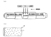
得られた焼結体は0.2~1.0(mm)の大きさになるように粉砕、分級し、さらにキュリー温度以下に一度冷却して磁気冷凍機に搭載する材料とした。当該焼結体の形状は特に限定されず、ランダムな粒状でよいが、より好ましくは球状であり、比表面積を高めることによってさらに効率的な熱交換が実現できる。分級した後にキュリー温度以下に冷却していない比較例1とともに、図1(a)に示すAMRに材料を搭載し、AMR両端の温度を測定した。
なお、当該焼結体の大きさは、特に上記に限定されず、図1(b)に示す収容容器10に充填した時に熱交換媒体(例えば水)が透過する大きさであればよいが、効率的な熱交換を実現するためには、0.2mmより小さいと通常の磁気冷凍機が熱交換媒体(例えば水)に加える圧力を考慮した際に熱交換媒体(例えば水)が透過し難くなるという点及び1.0mmを超えると熱交換媒体(例えば水)が当該焼結体に接触する表面積が十分に得られ難くなるという点から、0.2~1.0(mm)であることが好ましく、当該焼結体に接触する表面積を高めるという点から、より好ましくは0.2~0.7(mm)であり、さらに好ましくは0.2~0.4(mm)である。
このAMRでは、図1(b)に示すように、磁気冷凍用材料1は、ミリオーダーの粒子状で複数存在しており、収容容器10に充填されて収容されている。この収容容器10としては、透水性を有する容器であれば特に限定されず、熱交換媒体と磁気冷凍用材料1が熱交換できる形態であれば用いることが可能である。この収容容器10によって、媒体(例えば水)を透過させ、当該透過と共に、内部に収容された磁気冷凍用材料1と接触することによって、熱交換を行い、AMR両端で大きな温度差を生み出す。
AMR両端での温度測定は、アクリルパイプで作製したAMRを「一対の永久磁石(1テスラ)の中で励磁(磁気冷凍用材料が発熱-温度が上昇)→熱交換媒体(水)による熱交換→AMRを永久磁石から出して消磁(磁気冷凍用材料が吸熱-温度が低下)→熱交換媒体(水)を挿入したときとは逆方向に流し熱交換」この一連の動作を1サイクルとし、このサイクルを繰り返すことでAMRの中で温度勾配ができ両端に温度差がつくので、その温度を測定し磁気冷凍用材料の性能を測定した。中央の温度より高くなる方を高温端、低くなる方を低温端とした。なお温度測定はT型の熱電対で行った。これらの結果を表2に示す。
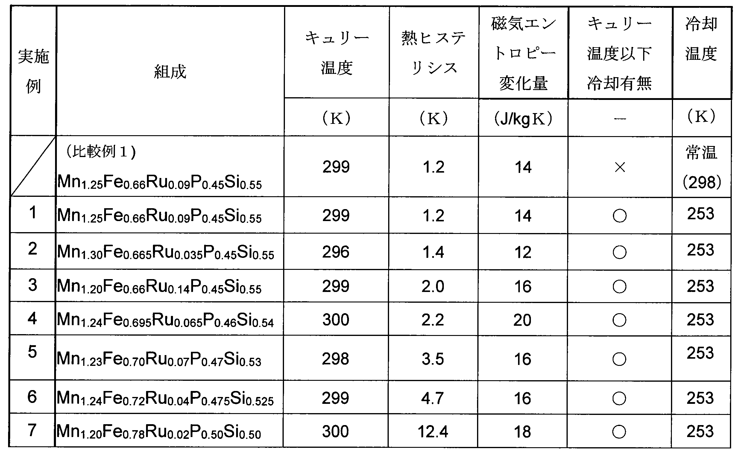

実施例1および比較例1から、破砕、分級後にキュリー温度以下に冷却していない材料はほとんど温度変化が得られないことが認められた。一方、破砕、分級後にキュリー温度以下に冷却した本発明に従う材料は大きな温度差が得られた。
実施例3、5、6から、それぞれの材料の磁気エントロピー変化量はほぼ同じであったが、熱ヒステリシスが大きくなるにつれて高温端と低温端の温度差は小さくなっていることが認められた。
実施例2、5、6、7から、実施例2は実施例5、6、7に比べると磁気エントロピー変化量が小さいにも関わらず、高温端と低温端で温度差が大きくなっていることからもわかるように、高温端と低温端で温度差を得るための絶対条件が材料の磁気エントロピー変化量ではなく、熱ヒステリシスが小さいことが重要であることが認められた。
実施例2、3、4から、実施例3、4は実施例2と比べると1Kほど熱ヒステリシスは大きいが、高温端と低温端でより大きな温度差が得られていた。このことから、熱ヒステリシスが小さいことは必須であるが、加えて熱ヒステリシスが2K程度の材料であれば磁気エントロピー変化量が大きければ高温端と低温端の温度差が熱ヒステリシス1K程度の材料と同等もしくはそれ以上になることが認められた。
比較例1および実施例1~7の結果から、磁気冷凍機のAMR内で大きな温度差(冷却性能)を得る要素としては、焼結体を焼成後キュリー温度以下に冷却することが最も重要であり、さらに熱ヒステリシスが2.2K以下で且つ磁気エントロピー変化量も大きい方が望ましいことが分かった。
さらに、以下では、種々のマンガン系磁気冷凍用材料(Mn系磁気冷凍用材料)の熱特性を確認すべく、種々のMn系磁気冷凍用材料の断熱温度変化の測定及び示差走査熱量測定(DSC)を行った。
(2)断熱温度変化の測定-1
Mn1.24Fe0.61Ru0.15P0.45Si0.55の組成を持つMn系磁気冷凍用材料の断熱温度変化を測定した。断熱温度変化が大きいほどAMRを作った時に温度変化が大きくなる。上記Mn系磁気冷凍用材料は15℃にキュリー温度を持つ材料である。焼成後のバルク材料をキュリー温度以下に冷やすことなく微粉末化し、その微粉末化した材料を10℃、0℃、-10℃、-20℃、-125℃まで冷却した材料と全く冷却していない材料を測定用試料とした。断熱温度変化の測定は18℃に設定した恒温室の中で、各々の温度まで冷却した試料を0.93テスラの永久磁石で励磁、消磁した時の温度変化の値とした。励磁前後での温度の差から求めたMn1.24Fe0.61Ru0.15P0.45Si0.55の断熱温度変化の値を以下の表に示す。

Mn1.24Fe0.61Ru0.15P0.45Si0.55の組成を持つMn系磁気冷凍用材料の断熱温度変化を測定した。断熱温度変化が大きいほどAMRを作った時に温度変化が大きくなる。上記Mn系磁気冷凍用材料は15℃にキュリー温度を持つ材料である。焼成後のバルク材料をキュリー温度以下に冷やすことなく微粉末化し、その微粉末化した材料を10℃、0℃、-10℃、-20℃、-125℃まで冷却した材料と全く冷却していない材料を測定用試料とした。断熱温度変化の測定は18℃に設定した恒温室の中で、各々の温度まで冷却した試料を0.93テスラの永久磁石で励磁、消磁した時の温度変化の値とした。励磁前後での温度の差から求めたMn1.24Fe0.61Ru0.15P0.45Si0.55の断熱温度変化の値を以下の表に示す。
得られた結果から明らかなように、キュリー温度付近までしか冷却していない材料の温度変化は小さかったが、キュリー温度より25℃低い温度まで冷却した試料は、全く冷却していない試料より2倍もの温度変化量があったことが確認された。
(3)示差走査熱量測定(DSC)-1
次に上記材料の示差走査熱量測定(DSC)を行った。示差走査熱量測定は測定試料と基準物質との間の熱量の差を計測することで、融点や磁性転移点などを測定する熱分析の手法である。
次に上記材料の示差走査熱量測定(DSC)を行った。示差走査熱量測定は測定試料と基準物質との間の熱量の差を計測することで、融点や磁性転移点などを測定する熱分析の手法である。
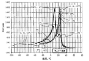
測定に使用したDSCはセイコーインスツル社製のEXTAR6100である。30mgの試料をアルミパンの中に入れ、基準物質にアルミナを選択し熱量の差を測定した。測定は25℃に設定した部屋の中で、試料がキュリー温度以下にならないように慎重に作製し、測定開始温度を60℃に設定し、-30℃まで冷却した。温度の走査速度は5℃/minとして測定した結果を、図2に示す(吹き出し線で示された温度は、冷却した温度を示す)。
Mn1.24Fe0.61Ru0.15P0.45Si0.55のDSC測定結果から求めた各材料の熱ヒステリシスは以下の通りであり、熱ヒステリシスの値はすべての試料で1K程度であった。
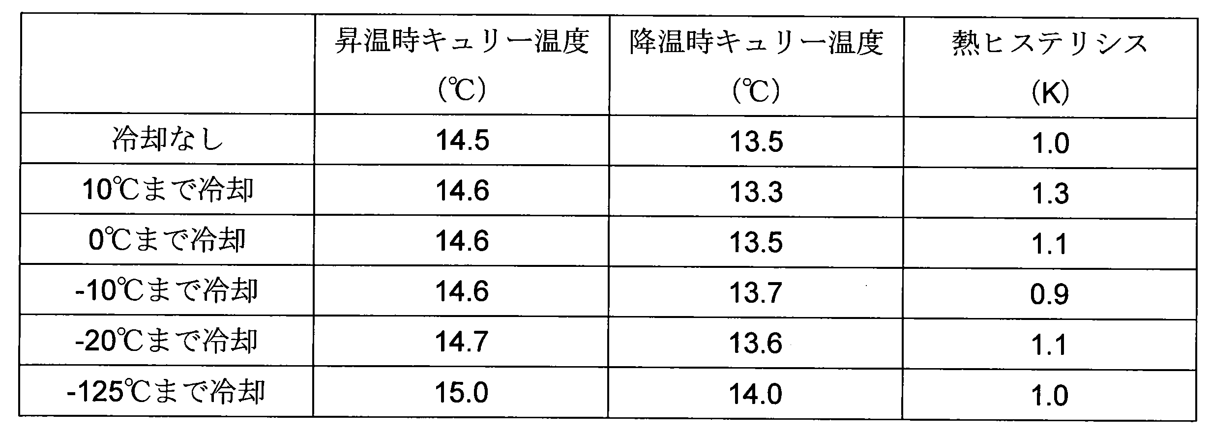
得られた結果から、冷却していない材料は1℃付近に転移点が認められたが、冷却温度が低くなるにつれて13℃付近の転移点(第1転移点)が確認できるようになった。また、10℃まで冷却した試料は1℃付近に、0℃まで冷却した試料は-3℃付近に、-10℃まで冷却した試料は-15℃付近に、-20℃まで冷却した試料は-26℃付近に第2の転移点が認められた。-125℃まで冷却した試料は、測定した範囲には第2の転移点が確認できなかった。各温度まで冷却した材料の断熱温度変化が異なっているのは、この第2の転移点の存在(準安定相)のためと推察される。材料の性能を最も引き出すためにはこの不要な転移をできる限り小さくする(なくす)必要があり、最低でもキュリー温度より25℃、好ましくは35℃以上冷却することが好ましく、さらに100℃以上キュリー温度より低い温度まで冷却すると、上述の第2の転移点(準安定相)は全て消失し、材料の性能が最も発揮できることが確認された。
以上の結果から、次のことが確認された。
・冷却していない材料の断熱温度変化(材料を励磁した時の温度変化)は小さく、その結果AMRで温度変化を測定したときに温度差が取れない。
・冷却温度によっても断熱温度変化の値は変わる。AMRで大きな温度変化を得るためにはキュリー温度より25℃低い温度まで冷却することが望ましい。
・AMRの温度変化を大きくするには熱ヒステリシスが小さいことは必須である。
・冷却温度を低くしていくと、本来あるべき温度にキュリー点が確認できるようになり、第2の転移点は低温方向にシフトし、その強度は下がっていく。DSCのグラフ(第2の転移点の強度の減衰)から推測するとキュリー温度より50℃程度低い温度まで冷却することがさらに望ましく、その場合には第2の相の影響はほぼなくなったことが確認された。
・冷却していない材料の断熱温度変化(材料を励磁した時の温度変化)は小さく、その結果AMRで温度変化を測定したときに温度差が取れない。
・冷却温度によっても断熱温度変化の値は変わる。AMRで大きな温度変化を得るためにはキュリー温度より25℃低い温度まで冷却することが望ましい。
・AMRの温度変化を大きくするには熱ヒステリシスが小さいことは必須である。
・冷却温度を低くしていくと、本来あるべき温度にキュリー点が確認できるようになり、第2の転移点は低温方向にシフトし、その強度は下がっていく。DSCのグラフ(第2の転移点の強度の減衰)から推測するとキュリー温度より50℃程度低い温度まで冷却することがさらに望ましく、その場合には第2の相の影響はほぼなくなったことが確認された。
(4)断熱温度変化の測定-2
Mn1.25Fe0.66Ru0.09P0.45Si0.55についても同様に試験を行った。上記Mn系磁気冷凍用材料は25℃にキュリー温度を持つ材料である。焼成後のバルク材料をキュリー温度以下に冷やすことなく微粉末化し、その微粉末化した材料を20℃、10℃、0℃、-10℃、-20℃、-55℃、-85℃、-125℃まで冷却した材料と全く冷却していない材料を測定用試料とした。
断熱温度変化の測定は28℃に設定した恒温室の中で、各々の温度まで冷却した試料を0.93テスラの永久磁石で励磁、消磁した時の温度変化の値とした。励磁前後での温度の差から求めたMn1.25Fe0.66Ru0.09P0.45Si0.55の断熱温度変化の値を以下の表に示す。
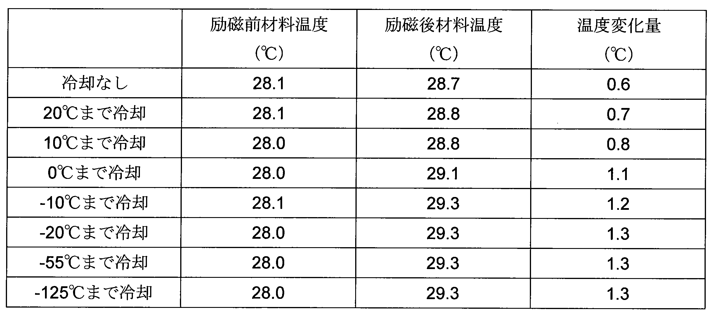
Mn1.25Fe0.66Ru0.09P0.45Si0.55についても同様に試験を行った。上記Mn系磁気冷凍用材料は25℃にキュリー温度を持つ材料である。焼成後のバルク材料をキュリー温度以下に冷やすことなく微粉末化し、その微粉末化した材料を20℃、10℃、0℃、-10℃、-20℃、-55℃、-85℃、-125℃まで冷却した材料と全く冷却していない材料を測定用試料とした。
断熱温度変化の測定は28℃に設定した恒温室の中で、各々の温度まで冷却した試料を0.93テスラの永久磁石で励磁、消磁した時の温度変化の値とした。励磁前後での温度の差から求めたMn1.25Fe0.66Ru0.09P0.45Si0.55の断熱温度変化の値を以下の表に示す。
キュリー温度付近までしか冷却していない材料の温度変化は小さいが、キュリー温度より35℃以上低い温度まで冷却した試料は、全く冷却していない試料より2倍の温度変化量があった。
(5)示差走査熱量測定(DSC)-2
上記と同様に、上記材料の示差走査熱量測定(DSC)を行った。即ち、30mgの試料をアルミパンの中に入れ、基準物質にアルミナを選択し熱量の差を測定した。測定は30℃に設定した部屋の中で、試料がキュリー温度以下にならないように慎重に作製し、測定開始温度を75℃に設定し、-20℃(冷却なし、20℃まで冷却した材料)、-30℃(10℃、0℃まで冷却した材料)、-40℃(-10℃まで冷却した材料)、-50℃(-20℃まで冷却した材料)、-100℃(-55℃、-85℃、-125℃まで冷却した材料)までの熱量の変化及び最大の熱量の差を取るときの温度(キュリー温度)を測定した結果を図3に示す(吹き出し線で示された温度は、冷却した温度を示す)。温度の走査速度は5℃/minで測定した。
上記と同様に、上記材料の示差走査熱量測定(DSC)を行った。即ち、30mgの試料をアルミパンの中に入れ、基準物質にアルミナを選択し熱量の差を測定した。測定は30℃に設定した部屋の中で、試料がキュリー温度以下にならないように慎重に作製し、測定開始温度を75℃に設定し、-20℃(冷却なし、20℃まで冷却した材料)、-30℃(10℃、0℃まで冷却した材料)、-40℃(-10℃まで冷却した材料)、-50℃(-20℃まで冷却した材料)、-100℃(-55℃、-85℃、-125℃まで冷却した材料)までの熱量の変化及び最大の熱量の差を取るときの温度(キュリー温度)を測定した結果を図3に示す(吹き出し線で示された温度は、冷却した温度を示す)。温度の走査速度は5℃/minで測定した。
Mn1.25Fe0.66Ru0.09P0.45Si0.55のDSC測定結果から求めた各冷却材料の熱ヒステリシスは以下の通りであり、熱ヒステリシスの値はすべての試料で1.5K程度であった。
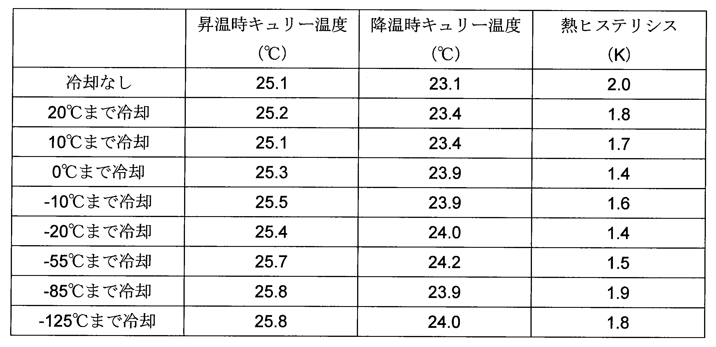
得られた結果から、DSCスペクトルは冷却温度によって大きく異なっていた。即ち、冷却していない材料は9℃付近に転移点が認められた。冷却温度が低くなるにつれて25℃付近の転移点が確認できるようになったが、20℃まで冷却した試料は8℃付近に、10℃まで冷却した試料は6℃付近に、0℃まで冷却した試料は-7℃付近に、-10℃まで冷却した試料は-19℃付近に、-20℃まで冷却した試料は-30℃付近に、第2の転移点が認められた。
また、-55℃、-85℃および-125℃まで冷却した試料は、明確な第2の転移点は確認できなかった。各温度まで冷却した材料の断熱温度変化が異なっているのは、この第2の転移点の存在(準安定相)のためであると推察される。材料の性能を最も引き出すためにはこの不要な転移をできる限り小さくする(なくす)必要があり、最低でもキュリー温度より25℃、好ましくは35℃以上冷却することが望ましい。さらに80℃以上キュリー温度より低い温度まで冷却すると、準安定相は全て消失し、材料の性能が最も発揮できることが確認された。
(6)断熱温度変化の測定-3
Mn1.25Fe0.70Ru0.05P0.46Si0.54の組成を持つMn系磁気冷凍用材料の断熱温度変化を測定した。上記Mn系磁気冷凍用材料は28℃にキュリー温度を持つ材料である。焼成後のバルク材料をキュリー温度以下に冷やすことなく微粉末化し、その微粉末化した材料を20℃、10℃、0℃、-10℃、-20℃、-55℃まで冷却した材料と全く冷却していない材料を測定用試料とした。
断熱温度変化の測定は30℃に設定した恒温室の中で、各々の温度まで冷却した試料を0.93テスラの永久磁石で励磁、消磁した時の温度変化の値とした。励磁前後での温度の差から求めたMn1.25Fe0.70Ru0.05P0.46Si0.54の断熱温度変化の値を以下の表に示す。
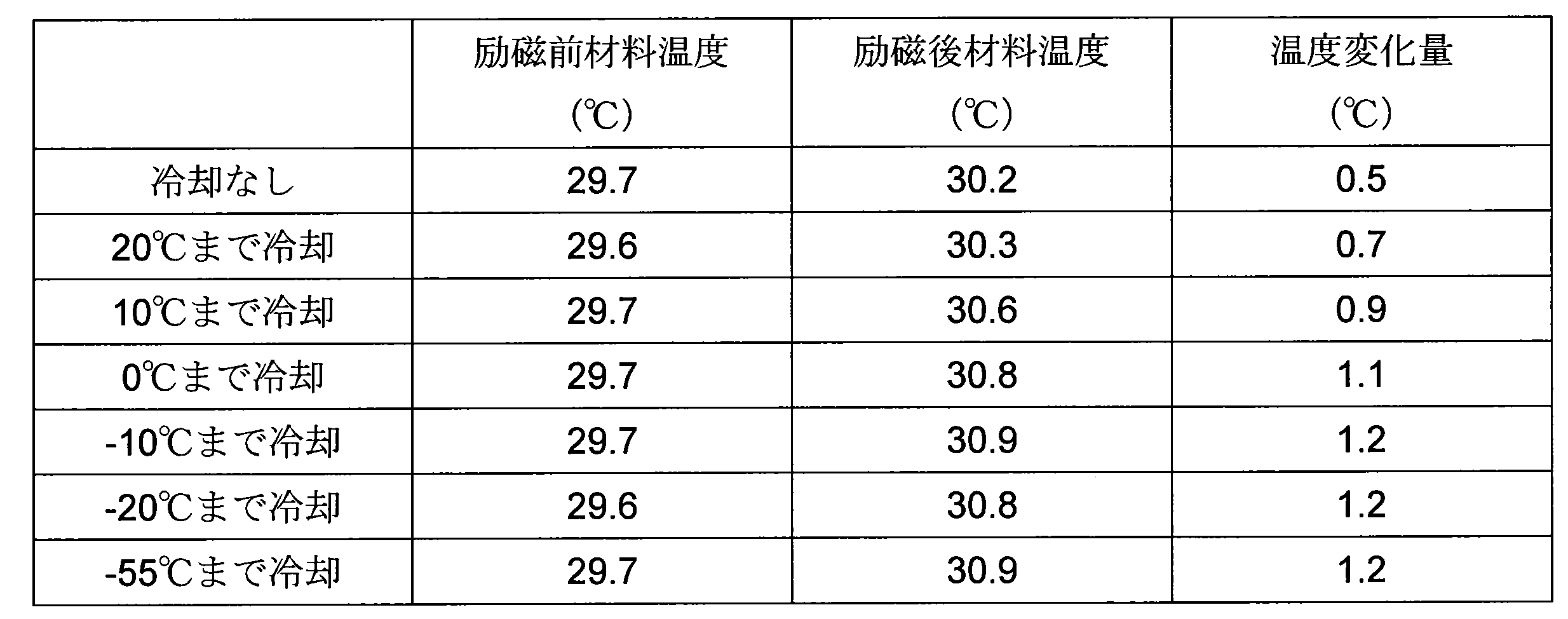
Mn1.25Fe0.70Ru0.05P0.46Si0.54の組成を持つMn系磁気冷凍用材料の断熱温度変化を測定した。上記Mn系磁気冷凍用材料は28℃にキュリー温度を持つ材料である。焼成後のバルク材料をキュリー温度以下に冷やすことなく微粉末化し、その微粉末化した材料を20℃、10℃、0℃、-10℃、-20℃、-55℃まで冷却した材料と全く冷却していない材料を測定用試料とした。
断熱温度変化の測定は30℃に設定した恒温室の中で、各々の温度まで冷却した試料を0.93テスラの永久磁石で励磁、消磁した時の温度変化の値とした。励磁前後での温度の差から求めたMn1.25Fe0.70Ru0.05P0.46Si0.54の断熱温度変化の値を以下の表に示す。
冷却していない材料の温度変化は小さいが、キュリー温度より30℃以上低い温度まで冷却した試料は、全く冷却していない試料より2倍の温度変化量があった。
(7)示差走査熱量測定(DSC)-3
上記と同様に、上記材料の示差走査熱量測定(DSC)を行った。即ち、30mgの試料をアルミパンの中に入れ、基準物質にアルミナを選択し熱量の差を測定した。測定は30℃に設定した部屋の中で、試料がキュリー温度以下にならないように慎重に作製し、測定開始温度を70℃に設定し、-15℃(冷却なし)-20℃(20℃まで冷却した材料)-30℃(10℃まで冷却した材料)-40℃(0℃まで冷却した材料)-50℃(-10℃まで冷却した材料)-60℃(-20℃まで冷却した材料)-85℃(-60℃まで冷却した材料)までの熱量の変化及び最大の熱量の差を取るときの温度(キュリー温度)を測定した結果を図4に示す(吹き出し線で示された温度は、冷却した温度を示す)。温度の走査速度は5℃/minで測定した。
上記と同様に、上記材料の示差走査熱量測定(DSC)を行った。即ち、30mgの試料をアルミパンの中に入れ、基準物質にアルミナを選択し熱量の差を測定した。測定は30℃に設定した部屋の中で、試料がキュリー温度以下にならないように慎重に作製し、測定開始温度を70℃に設定し、-15℃(冷却なし)-20℃(20℃まで冷却した材料)-30℃(10℃まで冷却した材料)-40℃(0℃まで冷却した材料)-50℃(-10℃まで冷却した材料)-60℃(-20℃まで冷却した材料)-85℃(-60℃まで冷却した材料)までの熱量の変化及び最大の熱量の差を取るときの温度(キュリー温度)を測定した結果を図4に示す(吹き出し線で示された温度は、冷却した温度を示す)。温度の走査速度は5℃/minで測定した。
Mn1.25Fe0.66Ru0.05P0.46Si0.54のDSC測定結果から求めた各冷却材料の熱ヒステリシスは以下の通りであり、熱ヒステリシスの値はすべての試料で2K程度であった。
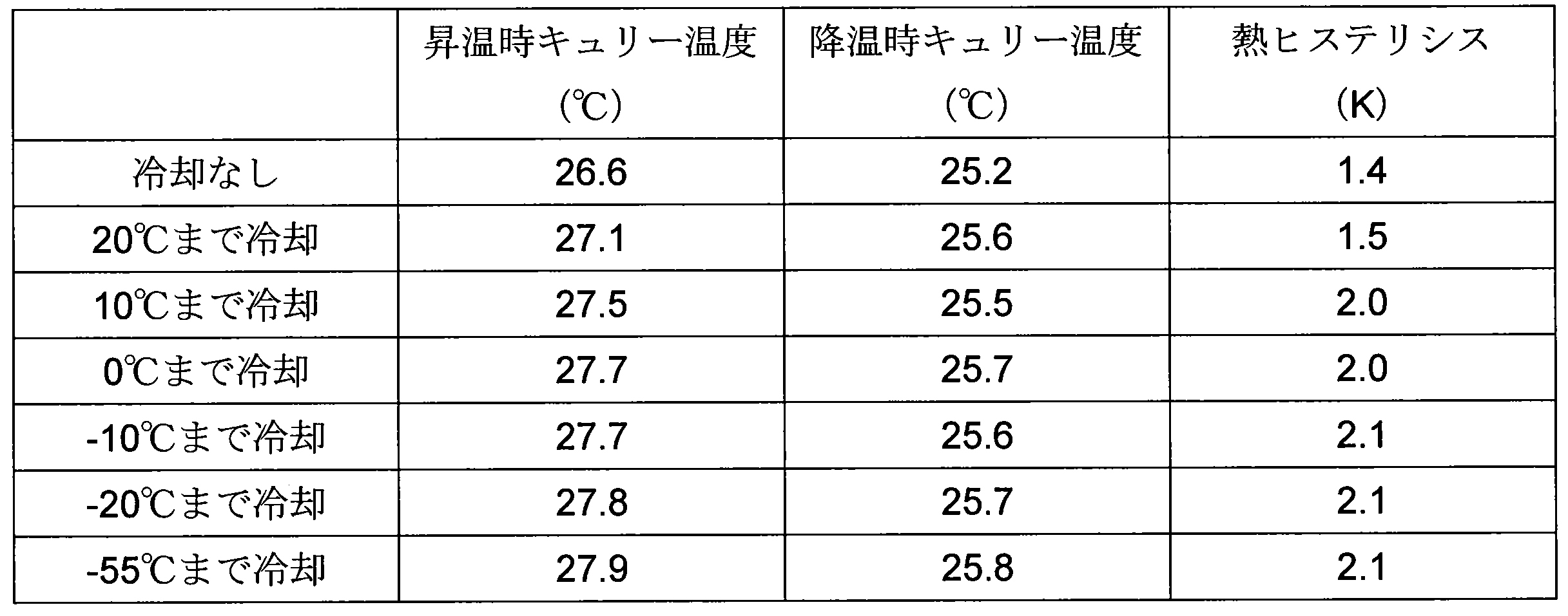
得られた結果から、DSCスペクトルは冷却温度によって大きく異なっていた。即ち、冷却していない材料は8℃付近に転移点が認められた。冷却温度が低くなるにつれて25℃付近の転移点の増大が確認できるようになったが、20℃まで冷却した試料は8℃付近に、10℃まで冷却した試料は6℃付近に、0℃まで冷却した試料は-10℃付近に、-10℃まで冷却した試料は-22℃付近に、-20℃まで冷却した試料は-30℃付近に、第2の転移点が認められた。
また、-60℃まで冷却した試料は、明確な第2の転移点は確認できなかった。各温度まで冷却した材料の断熱温度変化が異なっているのは、この第2の転移点の存在(準安定相)のためであると推察される。材料の性能を最も引き出すためにはこの不要な転移をできる限り小さくする(なくす)必要があり、最低でもキュリー温度より25℃、好ましくは35℃以上冷却することが望ましい。さらに80℃以上キュリー温度より低い温度まで冷却すると、準安定相は全て消失し、材料の性能が最も発揮できることが確認された。
10 収容容器
1 磁気冷凍用材料
1 磁気冷凍用材料
Claims (6)
- マンガンを含有するマンガン系化合物を、当該マンガン系化合物固有のキュリー温度以下に冷却する冷却工程を含むことを特徴とする磁気冷凍用材料の製造方法。
- 前記冷却工程が、前記マンガン系化合物を前記キュリー温度よりも25℃以下に冷却することを特徴とする請求項1に記載の磁気冷凍用材料の製造方法。
- 前記マンガン系化合物が、少なくともMn、Fe、Ru、P、及びSiの構成元素から構成されることを特徴とする請求項1又は2に記載の磁気冷凍用材料の製造方法。
- 前記マンガン系化合物が、一般式(Mn2-x―yFexAy)1+σ(P1-zBz)(A:Ni、Co、Ru、B:Ge、Si、B)(-0.1≦σ≦+0.1、0.6≦x≦1.2、0.03≦y≦0.7、0<z≦0.7)で表されることを特徴とする請求項1~3のいずれかに記載の磁気冷凍用材料の製造方法。
- 前記マンガン系化合物の熱ヒステリシスが2.2K以下であることを特徴とする請求項1~4のいずれかに記載の磁気冷凍用材料の製造方法。
- 請求項1~5のいずれかに記載の磁気冷凍用材料の製造方法により製造されることを特徴とする磁気冷凍用材料。
Priority Applications (1)
| Application Number | Priority Date | Filing Date | Title |
|---|---|---|---|
| JP2016566535A JP6606790B2 (ja) | 2014-12-26 | 2015-12-25 | 磁気冷凍用材料の製造方法 |
Applications Claiming Priority (2)
| Application Number | Priority Date | Filing Date | Title |
|---|---|---|---|
| JP2014265861 | 2014-12-26 | ||
| JP2014-265861 | 2014-12-26 |
Publications (1)
| Publication Number | Publication Date |
|---|---|
| WO2016104739A1 true WO2016104739A1 (ja) | 2016-06-30 |
Family
ID=56150751
Family Applications (1)
| Application Number | Title | Priority Date | Filing Date |
|---|---|---|---|
| PCT/JP2015/086313 Ceased WO2016104739A1 (ja) | 2014-12-26 | 2015-12-25 | 磁気冷凍用材料の製造方法 |
Country Status (2)
| Country | Link |
|---|---|
| JP (1) | JP6606790B2 (ja) |
| WO (1) | WO2016104739A1 (ja) |
Cited By (4)
| Publication number | Priority date | Publication date | Assignee | Title |
|---|---|---|---|---|
| CN108325714A (zh) * | 2018-03-30 | 2018-07-27 | 宁夏天元锰业有限公司 | 一种金属锰锭的破碎方法 |
| WO2018188178A1 (zh) * | 2017-04-13 | 2018-10-18 | 佛山市程显科技有限公司 | 一种mm'x-y金属复合功能材料及其制备方法 |
| CN110343934A (zh) * | 2019-07-24 | 2019-10-18 | 南京理工大学 | 掺杂Zn的Mn-Fe-P-Si基磁制冷材料及其制备方法 |
| JP2020152930A (ja) * | 2019-03-18 | 2020-09-24 | 大電株式会社 | 磁気冷凍材料 |
Citations (3)
| Publication number | Priority date | Publication date | Assignee | Title |
|---|---|---|---|---|
| JP2011523676A (ja) * | 2008-04-28 | 2011-08-18 | テクノロジー、ファウンデーション、エステーヴェー | 磁気冷却用またはヒートポンプ用の金属系材料の製造方法 |
| JP2013527308A (ja) * | 2010-03-11 | 2013-06-27 | ビーエーエスエフ ソシエタス・ヨーロピア | 磁気熱量材料 |
| JP2014015678A (ja) * | 2012-06-12 | 2014-01-30 | Kyushu Univ | 磁気冷凍材料 |
-
2015
- 2015-12-25 JP JP2016566535A patent/JP6606790B2/ja active Active
- 2015-12-25 WO PCT/JP2015/086313 patent/WO2016104739A1/ja not_active Ceased
Patent Citations (3)
| Publication number | Priority date | Publication date | Assignee | Title |
|---|---|---|---|---|
| JP2011523676A (ja) * | 2008-04-28 | 2011-08-18 | テクノロジー、ファウンデーション、エステーヴェー | 磁気冷却用またはヒートポンプ用の金属系材料の製造方法 |
| JP2013527308A (ja) * | 2010-03-11 | 2013-06-27 | ビーエーエスエフ ソシエタス・ヨーロピア | 磁気熱量材料 |
| JP2014015678A (ja) * | 2012-06-12 | 2014-01-30 | Kyushu Univ | 磁気冷凍材料 |
Cited By (6)
| Publication number | Priority date | Publication date | Assignee | Title |
|---|---|---|---|---|
| WO2018188178A1 (zh) * | 2017-04-13 | 2018-10-18 | 佛山市程显科技有限公司 | 一种mm'x-y金属复合功能材料及其制备方法 |
| CN108325714A (zh) * | 2018-03-30 | 2018-07-27 | 宁夏天元锰业有限公司 | 一种金属锰锭的破碎方法 |
| JP2020152930A (ja) * | 2019-03-18 | 2020-09-24 | 大電株式会社 | 磁気冷凍材料 |
| JP7134906B2 (ja) | 2019-03-18 | 2022-09-12 | 大電株式会社 | 磁気冷凍材料 |
| CN110343934A (zh) * | 2019-07-24 | 2019-10-18 | 南京理工大学 | 掺杂Zn的Mn-Fe-P-Si基磁制冷材料及其制备方法 |
| CN110343934B (zh) * | 2019-07-24 | 2021-06-11 | 南京理工大学 | 掺杂Zn的Mn-Fe-P-Si基磁制冷材料及其制备方法 |
Also Published As
| Publication number | Publication date |
|---|---|
| JPWO2016104739A1 (ja) | 2017-10-05 |
| JP6606790B2 (ja) | 2019-11-20 |
Similar Documents
| Publication | Publication Date | Title |
|---|---|---|
| Balli et al. | Advanced materials for magnetic cooling: Fundamentals and practical aspects | |
| Yibole et al. | Direct measurement of the magnetocaloric effect in MnFe (P, X)(X= As, Ge, Si) materials | |
| Lyubina | Magnetocaloric materials for energy efficient cooling | |
| Li et al. | Giant low field magnetocaloric effect and field-induced metamagnetic transition in TmZn | |
| Anwar et al. | Enhanced relative cooling power of Ni1− xZnxFe2O4 (0.0⩽ x⩽ 0.7) ferrites | |
| JP6606790B2 (ja) | 磁気冷凍用材料の製造方法 | |
| Gorsse et al. | Magnetocaloric effect and refrigeration capacity in Gd60Al10Mn30 nanocomposite | |
| US20080276623A1 (en) | Magnetic refrigerant material | |
| KR102147433B1 (ko) | 자기 냉각기 및 이를 포함하는 장치 | |
| JP6009994B2 (ja) | 磁気冷凍材料 | |
| Lei et al. | Magnetocaloric effect and applied refrigeration performance of La (Fe, Si) 13-based compounds | |
| Do et al. | Effect of Cerium Doping on Crystal Structure and Magnetic Properties of La1− yCeyFe11. 44Si1. 56 Compounds | |
| US20130134348A1 (en) | Magnetic Materials and Systems | |
| JP6648884B2 (ja) | 磁気冷凍材料 | |
| JP2014228166A (ja) | 磁気冷凍装置用磁気作業物質および磁気冷凍装置 | |
| Brock et al. | The effect of Fe doping on the magnetic and magnetocaloric properties of Mn5− xFexGe3 | |
| JP2020152930A (ja) | 磁気冷凍材料 | |
| JP6205839B2 (ja) | 磁気冷凍装置用磁気作業物質および磁気冷凍装置 | |
| KR102651747B1 (ko) | 자기열량합금 및 이의 제조방법 | |
| Zheng et al. | The magnetic, structural properties and magnetocaloric effects of Fe-Mn-Al alloys | |
| Chaudhary | Study of iron based magnetocaloric nanomaterials | |
| Neupane | Magnetocaloric Effect in Oxide Materials | |
| Yang Nurhidayah Asnida | Effect of different heat treatment annealing and substitution of lanthanum (La) with yttrium (Y) In La (Fe, Si) 13 compounds | |
| KR101870830B1 (ko) | 신규 자기열 물질 및 그 제조방법 | |
| Javed | Magnetic Refrigerator Device Based on La (FexCoySi1-xy) 13 |
Legal Events
| Date | Code | Title | Description |
|---|---|---|---|
| 121 | Ep: the epo has been informed by wipo that ep was designated in this application |
Ref document number: 15873307 Country of ref document: EP Kind code of ref document: A1 |
|
| ENP | Entry into the national phase |
Ref document number: 2016566535 Country of ref document: JP Kind code of ref document: A |
|
| NENP | Non-entry into the national phase |
Ref country code: DE |
|
| 122 | Ep: pct application non-entry in european phase |
Ref document number: 15873307 Country of ref document: EP Kind code of ref document: A1 |