WO2016104343A1 - 管内作業装置 - Google Patents
管内作業装置 Download PDFInfo
- Publication number
- WO2016104343A1 WO2016104343A1 PCT/JP2015/085437 JP2015085437W WO2016104343A1 WO 2016104343 A1 WO2016104343 A1 WO 2016104343A1 JP 2015085437 W JP2015085437 W JP 2015085437W WO 2016104343 A1 WO2016104343 A1 WO 2016104343A1
- Authority
- WO
- WIPO (PCT)
- Prior art keywords
- pipe
- state
- connecting member
- connecting members
- inspection
- Prior art date
- Legal status (The legal status is an assumption and is not a legal conclusion. Google has not performed a legal analysis and makes no representation as to the accuracy of the status listed.)
- Ceased
Links
Images







Classifications
-
- E—FIXED CONSTRUCTIONS
- E03—WATER SUPPLY; SEWERAGE
- E03F—SEWERS; CESSPOOLS
- E03F7/00—Other installations or implements for operating sewer systems, e.g. for preventing or indicating stoppage; Emptying cesspools
-
- F—MECHANICAL ENGINEERING; LIGHTING; HEATING; WEAPONS; BLASTING
- F16—ENGINEERING ELEMENTS AND UNITS; GENERAL MEASURES FOR PRODUCING AND MAINTAINING EFFECTIVE FUNCTIONING OF MACHINES OR INSTALLATIONS; THERMAL INSULATION IN GENERAL
- F16B—DEVICES FOR FASTENING OR SECURING CONSTRUCTIONAL ELEMENTS OR MACHINE PARTS TOGETHER, e.g. NAILS, BOLTS, CIRCLIPS, CLAMPS, CLIPS OR WEDGES; JOINTS OR JOINTING
- F16B1/00—Devices for securing together, or preventing relative movement between, constructional elements or machine parts
- F16B1/02—Means for securing elements of mechanisms after operation
-
- F—MECHANICAL ENGINEERING; LIGHTING; HEATING; WEAPONS; BLASTING
- F16—ENGINEERING ELEMENTS AND UNITS; GENERAL MEASURES FOR PRODUCING AND MAINTAINING EFFECTIVE FUNCTIONING OF MACHINES OR INSTALLATIONS; THERMAL INSULATION IN GENERAL
- F16L—PIPES; JOINTS OR FITTINGS FOR PIPES; SUPPORTS FOR PIPES, CABLES OR PROTECTIVE TUBING; MEANS FOR THERMAL INSULATION IN GENERAL
- F16L55/00—Devices or appurtenances for use in, or in connection with, pipes or pipe systems
- F16L55/18—Appliances for use in repairing pipes
-
- F—MECHANICAL ENGINEERING; LIGHTING; HEATING; WEAPONS; BLASTING
- F16—ENGINEERING ELEMENTS AND UNITS; GENERAL MEASURES FOR PRODUCING AND MAINTAINING EFFECTIVE FUNCTIONING OF MACHINES OR INSTALLATIONS; THERMAL INSULATION IN GENERAL
- F16L—PIPES; JOINTS OR FITTINGS FOR PIPES; SUPPORTS FOR PIPES, CABLES OR PROTECTIVE TUBING; MEANS FOR THERMAL INSULATION IN GENERAL
- F16L55/00—Devices or appurtenances for use in, or in connection with, pipes or pipe systems
- F16L55/26—Pigs or moles, i.e. devices movable in a pipe or conduit with or without self-contained propulsion means
- F16L55/28—Constructional aspects
- F16L55/30—Constructional aspects of the propulsion means, e.g. towed by cables
Definitions
- the present invention relates to an in-pipe working apparatus that is inserted into a pipe and performs work inside the pipe.
- an in-pipe working device that is inserted into an existing pipe such as a water and sewage pipe or a gas pipe and performs work inside the pipe is known.
- Patent Document 1 includes a support ring and a warp-like member provided at each of the front end portion and the rear end portion of the support ring, and the support ring is brought into contact with the inner wall of the pipe.
- An in-pipe investigation device adapted to be supported is disclosed.
- the warped member at the front end protrudes forward and in the diameter increasing direction from the support ring, and the warped member at the rear end protrudes rearward and in the diameter increasing direction from the support ring.
- the present invention has been made in view of the above problems, and an object of the present invention is to provide an in-pipe working apparatus that can be easily inserted into a pipe and operated in the pipe.
- An in-pipe work apparatus is an in-pipe work apparatus that is inserted into a pipe to perform the in-pipe work, and includes a main body unit that includes a plurality of connecting members arranged in a predetermined direction, A linear member fixed in part, and a telescopic member that expands and contracts in a direction intersecting the predetermined direction by changing a tension between the linear members to change a distance between the connecting members. It is characterized by.
- the elastic member can be expanded and contracted by changing the tension of the linear member.
- the expansion member can be contracted to reduce the outer diameter of the in-pipe working device
- the in-pipe working device can be inserted into the pipe through a small opening such as a branch pipe provided in the pipe.
- the in-pipe work can be performed by extending the telescopic member by changing the tension of the linear member. Therefore, unlike the prior art, the in-pipe working device is installed in the pipe using a small opening such as a branch pipe without disassembling the joint portion of the pipe or providing a large opening for inserting the in-pipe work device into the pipe. Therefore, the work in the pipe can be easily performed.
- expansion / contraction member may be a positioning leg portion that contacts the inner wall of the tube and positions the tube working device with respect to the tube.
- the positioning leg can be extended by changing the tension of the linear member, thereby positioning the in-pipe working device.
- a configuration may be provided that includes an inspection device for inspecting the pipe.
- the pipe can be easily inspected without disassembling the joint portion of the pipe or providing a large opening for inserting the in-pipe working device into the pipe as in the prior art. .
- the inspection device may be attached to the elastic member.
- the expansion member after inserting the in-pipe working device into the tube, the expansion member can be extended by changing the tension of the linear member, and the inspection device can be placed at a predetermined inspection position.
- tensile_strength of the said linear member in the direction away is arrange
- the contracting member contracts to a position close to the connecting member, and a tension of a predetermined value or more is applied to the linear member.
- the elastic member can be easily switched between the contracted state and the extended state by changing the tension between the linear members to change the interval between the connecting members.
- the said expansion-contraction member is provided with the 1st connection rod group and 2nd connection rod group which consist of several connection rods which edge parts mutually connected rotatably,
- the connection rods which comprise each said connection rod group are included.
- the first connecting rod group has one end of the deformable truss structure arranged so as to alternately intersect with each other, and one end of the first connecting rod group is attached to one of the connecting members, and the second connecting One end of the bar group may be configured to be attached to the other of the connecting members whose interval is changed.
- the elastic member can be easily switched between the contracted state and the extended state by changing the tension between the linear members to change the interval between the connecting members.
- a tip member attached to the other end of the first connecting rod group and the other end of the second connecting rod group, the expandable member extends to a position where the tip member contacts the inner wall of the tube, It is good also as a structure provided with the front-end
- the tip member can be pressed against the inner wall of the tube by the urging force of the tip urging member, so that the contact state between the expandable member and the inner wall of the tube can be stabilized.
- a plurality of sets of the connecting members whose intervals are changed by changing the tension of the linear members are provided, and a plurality of the positioning members are respectively provided at positions corresponding to two or more of the plurality of sets of the connecting members. It is good also as a structure provided with the leg part.
- the in-pipe working device can be supported at a plurality of positions along the extending direction of the main body, the in-pipe working device can be supported more stably.
- the distance between the connecting members according to the change in the tension of the linear member. It is good also as a structure by which the inspection leg part extended and contracted in the direction which cross
- the inspection device can be moved in a direction approaching the inner wall of the tube by changing the tension of the linear member.
- a first elastic member that biases the pair of connecting members corresponding to the positioning leg portions away from each other and a second elastic member that biases the pair of connecting members corresponding to the inspection leg portions away from each other.
- An elastic member is disposed, and the second elastic member has a stronger elastic force than the first elastic member, and the linear member is relaxed from the first state in which the linear member is relaxed, and a tension greater than a predetermined value is applied to the linear member.
- the positioning leg portion extends to a position where it abuts against the inner wall of the tube, and the linear member is moved from the second state to a second predetermined value greater than the predetermined value. It is good also as a structure which the said leg part for a test
- the inspection device after positioning the main body by switching to the second state and extending the positioning leg to a position where it abuts against the inner wall of the pipe, the inspection device is switched to the third state to check the inspection device. Therefore, the inspection apparatus can be positioned with high accuracy.
- it may be configured to include a drive unit that rotates the inspection apparatus along a rotation axis substantially parallel to the predetermined direction.
- a wide area along the circumferential direction of the pipe can be inspected by the inspection apparatus.
- the linear member includes an inner wire having one end side penetrating at least a part of the connecting member and fixed to a part of the main body portion, and the other end side exposed from the end portion of the main body portion in the predetermined direction.
- An outer wire that is fixed to the end of the main body and covers a portion of the inner wire that is exposed from the end of the main body, and the interwire is connected to the outer wire. The distance between the connecting members may be changed by changing the tension of the inner wire.
- the extension state of the elastic member can be easily controlled by changing the tension of the inner wire.
- An in-pipe work apparatus is an in-pipe work apparatus that is inserted into a pipe and performs the in-pipe work, and includes a plurality of connection members connected in a predetermined direction, and the plurality of connection members Are a connecting member having an extending part having a body part extending in the predetermined direction and a curved surface part provided at a front end of the body part, and a connecting member having an accommodating part for accommodating the front end of the extending part;
- the body portion is detached from the housing portion in a state where the curved surface portion is housed in the housing portion, and the body portion is in the predetermined direction with the curved surface portion housed in the housing portion as an axis.
- Second state in which bending in the predetermined direction is restricted It is characterized in that it is switchable.
- a main-body part can be bent with respect to an axial direction in a 1st state, an in-pipe working apparatus can be easily inserted in a pipe
- the elastic member can be expanded and contracted by changing the tension of the linear member.
- the expansion member can be contracted to reduce the outer diameter of the in-pipe working device
- the in-pipe working device can be inserted into the pipe through a small opening such as a branch pipe provided in the pipe.
- the in-pipe work can be performed by extending the telescopic member by changing the tension of the linear member. Therefore, unlike the prior art, the in-pipe working device is installed in the pipe using a small opening such as a branch pipe without disassembling the joint portion of the pipe or providing a large opening for inserting the in-pipe work device into the pipe. Therefore, the work in the pipe can be easily performed.
- FIG. 2 is a cross-sectional view when the in-pipe work apparatus in FIG. 1 is in the first state, wherein (a) to (c) are an AA cross section, a BB cross section, and a CC cross section in FIG. Is shown. It is explanatory drawing which shows an external appearance in case the in-pipe work apparatus of FIG. 1 is the said 3rd state. It is explanatory drawing which shows operation
- a top view and (c) are side views in a state where the positioning leg portion is extended.
- FIG. 1 is an explanatory diagram showing a schematic configuration of an in-pipe work apparatus 1 according to the present embodiment. As shown in this figure, the in-pipe work device 1 is inserted into a pipe 2 from a branch pipe 3 provided in the pipe 2 and performs a predetermined work inside the pipe 2.
- the in-pipe work apparatus 1 is a pipe inspection apparatus that inspects the pipe 2
- the use of the in-pipe work apparatus 1 is not limited to this, and for example, cleaning the inside of the pipe is performed.
- the present invention can also be applied to a pipe cleaning device to be performed, a pipe repair device for repairing a pipe, an imaging device for photographing the inside of the pipe, a substance collecting device for collecting a substance in the pipe, and the like.
- the pipe 2 is a pipe for transporting a fluid such as a water and sewage pipe or a gas pipe.
- the branch pipe 3 is a branch pipe having a smaller diameter than the pipe 2 branched from the pipe 2 for attaching an air valve or the like to the pipe 2.
- this embodiment demonstrates the example in case the internal diameter of the pipe
- the in-pipe working device 1 includes a main body portion 10 extending in the axial direction (predetermined direction), a wire cable (front end side cable) 11 attached to the front end of the main body portion 10, and a main body portion.
- 10 includes a wire cable (rear end side cable, linear member) 12 inserted into the main body 10 from the rear end side, and an operation jig 13 for performing an expansion / contraction operation of the main body portion 10.
- One end of the wire cable 12 passes through the inside of the main body 10 along the axial direction and is attached to the vicinity of the tip of the main body 10, and the other end is attached to the operation jig 13.
- the main body 10 includes a first elastic part 14, a second elastic part 15, a third elastic part 16, a first joint part 17, a second joint part 18, positioning leg parts (extensible members) 19 and 21, and inspection legs.
- a part (extensible member) 20 and a motor (drive part) 22 are provided.
- 2 (a) to 2 (c) are explanatory views showing the configuration of the wire cable 12, the configuration of the operation jig 13, and the configuration of the connection portion of the wire cable 12 to the main body portion 10, respectively.
- the wire cable 12 includes an inner wire 31, an outer wire 32, outer ends 33a and 33b, inner connection portions 34a and 34b, wire ends 35a and 35b, lock nuts 36a to 36f, and a handle portion 37. It has.
- the operation jig 13 includes a substrate 40 extending along the extending direction of the wire cable 12, an outer mounting plate 41 and a U-shaped plate protruding from the substrate 40 in a direction substantially perpendicular to the plate surface of the substrate 40. 42a, 42b, 42c are provided.
- the outer mounting plate 41 is provided with a hole (not shown) through which the inner wire 31 is inserted.
- the U-shaped plates 42a to 42c are formed with groove portions (not shown) in which the end portions on the side far from the substrate 40 are cut out in a U-shape.
- One end side of the inner wire 31 is fixed to the wire end 35b by the inner connection portion 34b, and the other end side is fixed to the wire end 35a by the inner connection portion 34a.
- the method for fixing the inner wire 31 to the wire ends 35a, 35b is not particularly limited, and for example, a method such as caulking can be used.
- the outer wire 32 is a tube-shaped member that covers the periphery of the inner wire 31, and has an outer end 33b attached to one end side and an outer end 33a attached to the other end side. Further, lock nuts 36d and 36e are attached to the outer end 33a, and a lock nut 36f is attached to the outer end 33b. The lock nut 36 f is for attaching the outer end 33 b to the main body 10. The lock nuts 36d and 36e are for attaching the outer end 33a to the operation jig 13 by sandwiching the outer attachment plate 41 of the operation jig 13 by the lock nuts 36d and 36e. Thereby, the inner wire 31 is covered with the outer wire 32 between the main body 10 and the operation jig 13.
- the material of the outer wire 32 is not particularly limited, but can be bent with respect to the stretching direction when the in-pipe working device 1 is inserted into the pipe, and is not easily deformed by a compressive load in the stretching direction.
- a material is preferred.
- a tube made of polyvinyl chloride (PVC) is used as the outer wire 32.
- the outer wire 32 may have a configuration in which a reinforcing member such as a steel wire is provided inside, or may have a configuration in which a reinforcing spring or the like is provided along the outer periphery of the outer wire 32.
- One end side of the inner wire 31 is exposed from the end portion of the outer wire 32 on the main body portion 10 side, and passes through the inside of the main body portion 10 as shown in FIG.
- a wire end 35 b attached to the side is fixed to a connecting member 110 disposed on the distal end side of the main body 10.
- the other end side of the inner wire 31 is exposed from the end portion of the outer wire 32 on the operation jig 13 side, and a lock nut 36a is attached to the end portion of the wire end 35a attached to the other end side of the inner wire 31.
- the handle part 37 is attached by the above.
- the operator of the in-pipe working device 1 holds the handle portion 37 and operates the wire cable 12 in the extending direction, so that the lock nuts 36b and 36c attached to the wire end 35a become the U-shape of the operation jig 13. It is hooked on one of the plates 42a to 42c.
- the inner wire 31 moves in the outer wire 32 relative to the outer wire 32 in the longitudinal direction, and the length of the portion exposed from the outer wire 32 to the main body 10 side, that is, The length from the outer end 33b to the wire end 35b changes.
- the state where the lock nuts 36b and 36c are hooked on the U-shaped plate 42a is the first state
- the state where the lock nuts 36b are hooked on the U-shaped plate 42b is the second state
- the state where the lock nuts 36b and 36c are hooked on the U-shaped plate 42c Is referred to as a third state.
- the material of the inner wire 31 is not particularly limited as long as it is a material that can be bent with respect to the extending direction when the in-pipe working device 1 is inserted into the tube and has an appropriate strength against a tensile load in the extending direction.
- a lubricant may be applied to a portion of the inner wire 31 covered with the outer wire 32.
- the wire cable (front end side cable) 11 is attached to an eye nut 114 fixed to the front end side of the connecting member 110.
- the wire cable 11 is pulled out of the pipe 2 from a branch portion (not shown) different from the branch pipe 3 in the pipe 2, and pulling the wire cable 11 causes the in-pipe working device 1 to move in the pipe 2. It has become.
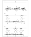
- FIG. 3A and 3B are cross-sectional views showing the configuration of the main body 10, where FIG. 3A shows the first state, FIG. 3B shows the second state, and FIG. 3C shows the third state.
- the main body 10 includes a first elastic part 14, a second elastic part 15, a third elastic part 16, a first joint part 17, and a second joint part 18.
- the first extendable portion 14 is provided with positioning leg portions (expandable members) 19 at three substantially equal intervals along the circumferential direction
- the second extendable portion 15 has a central axis of the main body portion 10.
- inspection leg portions (stretchable members) 20 are provided with inspection leg portions (stretchable members) 20 at two symmetrical positions
- the third stretchable portion 16 has positioning leg portions (stretchable at three locations at substantially equal intervals along the circumferential direction).
- Member 21 is provided.
- the first joint portion 17 and the second joint portion 18 are in a state that can be bent with respect to the axial direction. Thereby, the main-body part 10 can be easily inserted in the pipe 2 from the branch pipe 3.
- FIG. 1
- the first stretchable portion 14 and the third stretchable portion 16 are contracted, while the second stretchable portion 15 is maintained in the stretched state.
- the positioning leg portions 19 and 21 extend and abut against the inner wall of the tube 2, and the main body portion 10 of the main body portion 10 substantially coincides with the axial center of the main body portion 10 by the positioning leg portions.
- the inspection leg 20 is maintained in a contracted state to a position close to the main body 10.
- the first joint portion 17 is in a state where bending in the axial direction is restricted (a state where the bending is not refracted in the axial direction), and the second joint portion 18 is maintained in a state in which bending is possible in the axial direction. Is done.
- the first stretchable portion 14, the third stretchable portion 16, and the second stretchable portion 15 are all contracted.
- the positioning legs 19 and 21 are extended and maintained in contact with the inner wall of the tube 2, and the inspection leg 20 is extended so that the tip of the inspection leg 20 is at a predetermined inspection position. It extends to the position where it contacts the pipe 2 in the example of FIG.
- the first joint portion 17 and the second joint portion 18 are in a state where bending in the axial direction is restricted (a state where the bending is not refracted in the axial direction).
- FIG. 5 is an explanatory diagram showing the configuration of the main body 10 in the third state.
- each of the three positioning leg portions 19 and 21 extends and abuts against the inner wall of the tube 2, so that the axis of the main body 10 substantially coincides with the axis of the tube 2.
- the main body 10 is supported.
- the two inspection leg portions 20 extend, and an inspection device (not shown) provided at the tip of the inspection leg portion 20 is disposed at a predetermined inspection position.
- the configuration of the inspection apparatus is not particularly limited.
- various apparatuses for inspecting a tube such as an overflow flaw detection apparatus, an ultrasonic flaw detection apparatus, and an imaging apparatus can be used.
- the predetermined inspection position is a position for inspecting the tube 2 using an inspection device (not shown) attached to the tip of the inspection leg 20, and depends on the type and characteristics of the inspection device. Set accordingly.
- the inspection position may be a position where the inspection device contacts the inner wall of the tube 2, a position near the inner wall of the tube 2, or a position away from the inner wall of the tube 2 by a predetermined distance. There may be.
- the inspection leg 20 may be omitted, and the inspection apparatus may be attached to the main body 10, the positioning leg 19, or the positioning leg 21.
- three positioning legs 19 and 21 are provided along the circumferential direction.
- the number of positioning legs 19 and 21 is not limited to this, and the main body 10 is stabilized. Any configuration can be used as long as it can be supported.
- one of the positioning legs 19 and 21 may be omitted, and another positioning leg (not shown) may be provided in addition to the positioning legs 19 and 21.
- FIG. 6A and 6B are explanatory views showing the relationship between the tension state of the inner wire 31 in the wire cable 12 and the expansion / contraction state of each part of the main body 10, wherein FIG. 6A is the first state, and FIG. 6B is the second state.
- FIG. 6A is the first state
- FIG. 6B is the second state.
- C has shown the 3rd state.
- the main body 10 is connected to the connecting members 50, 60, 70, 80, 90, 100, and 110 arranged in series along the axial direction. It has a structure.
- the connecting member 50 includes a base portion 50a and an extending portion 51 extending from the base portion 50a to the connecting member 60 side along the axial direction of the main body portion 10.
- the extending portion 51 includes a trunk portion 52 provided on the base side (base portion 50a side), a spherical portion 54 that is a curved surface portion provided on the distal end side, and a small diameter portion that connects the trunk portion 52 and the spherical portion 54. 53.
- the outer diameter of the body portion 52 in the direction perpendicular to the extending direction and the outer diameter of the spherical portion 54 in the same direction are substantially the same, and the outer diameter of the small diameter portion 53 in the above direction is the same as that of the body portion 52 and the spherical portion 54.
- the base unit 50a is not an essential configuration and may be omitted.
- the base portion 50 a may be omitted, and the connecting member 50 may be configured by only the extending portion 51, and the leg attaching portion 55 may be provided on the body portion 52 of the extending portion 51.
- the outer diameter of the body portion 52 and the outer diameter of the spherical portion 54 are substantially the same, and a small-diameter portion 53 having a smaller outer diameter than both of the members is provided between the body portion 52 and the spherical portion 54. It is provided, but is not limited to this.
- the outer diameter of the body portion 52 may be made smaller than the outer diameter of the spherical portion 54, and the small diameter portion 53 may be omitted.
- the small-diameter portion 53 is omitted, the outer diameter of the connecting portion with the spherical portion 54 in the trunk portion 52 is reduced, and the outer diameter of the trunk portion 52 decreases toward the distal end side. May be smaller than the outer diameter of the spherical portion 54.
- the connecting member 60 includes a through hole 61 having an inner diameter slightly larger than the outer diameter of the extending portion 51 through which the extending portion 51 of the connecting member 50 is inserted. Further, on the outer peripheral surface of the connecting member 60 in the vicinity of the portion facing the connecting member 50, leg attaching portions 62 for attaching the positioning leg portions 19 are provided at positions corresponding to the leg attaching portions 55 of the connecting member 50, respectively. Is provided.
- a spring (first elastic member) 56 is disposed between the connecting member 50 and the connecting member 60 (the first telescopic part 14) along the outer periphery of the extending part 51. 60 is biased in a direction away from each other by a spring 56.
- the connecting member 70 includes an accommodating portion 71 having an inner diameter slightly larger than the outer diameter of the extending portion 51 for accommodating the extending portion 51 penetrating the connecting member 60 on the surface facing the connecting member 60. . Further, a spring (restoring elastic member) 63 (see FIG. 1) is disposed along the outer peripheral surface of both the connecting members at the connecting portion (first joint portion 17) between the connecting member 60 and the connecting member 70. Yes. When an external force is not acting between the connecting member 60 and the connecting member 70, the spring 63 urges the connecting members in a direction in which the connecting members are brought into contact with each other with their axial centers substantially coincident with each other.
- the spring 63 provides a restoring force that restores the relative position (relative angle) of these two members to the initial position where the mutual axes are substantially coincident with each other. is doing.
- the connecting member 60 is not an essential component and may be omitted.
- the connecting member 60 may be omitted, and the spring 56 may be disposed along the outer periphery of the extending portion 51 between the connecting member 50 and the connecting member 70.
- the spring 56 is placed in the accommodating portion 71 of the connecting member 70 (the spherical portion 54 of the connecting member 50 and the bottom surface of the accommodating portion 71 (the end portion of the accommodating portion far from the connecting member 50)). (Between).
- the leg attaching portion 62 may be provided on the connecting member 70.
- the restoring force is applied by the spring 63, but the present invention is not limited to this.
- an elastic member such as rubber is disposed along the circumferential direction in a portion that contacts the spherical portion 54 in the first state in the accommodating portion 71 of the connecting member 70, and the spherical member 54 of the connecting member 50 is engaged with the elastic member. It is good also as a structure which provides the groove
- a motor (driving unit) 22 for rotating the coupling members 80 and 90 along the axial direction of the main body 10 is attached to the coupling member 70.
- FIG. 7 is an explanatory diagram showing a configuration of a connection portion between the motor 22 and the connecting member 80.
- an external gear 22 b is formed on the drive shaft 22 a of the motor 22.
- the surface of the connecting member 80 on the side of the connecting member 70 has a substantially cylindrical shape opened to the connecting member 70 side, and the cylindrical inner peripheral surface is formed with a tooth surface that meshes with the external gear 22b of the motor 22. It has become an internal gear.
- the connecting member 80 includes a base portion 80a and an extending portion 81 extending from the base portion 80a to the connecting member 90 side along the axial direction of the main body portion 10.
- the extending portion 81 includes a body portion 82 provided on the base side (base portion 80a side), a spherical portion 84 that is a curved surface portion provided on the distal end side, and a small diameter portion that connects the body portion 82 and the spherical portion 84. 83.
- the outer diameter of the body portion 82 in the direction perpendicular to the extending direction and the outer diameter of the spherical portion 84 in the same direction are substantially the same, and the outer diameter of the small diameter portion 83 in the above direction is the same as that of the body portion 82 and the spherical portion 84. It is smaller than the outer diameter.
- leg attaching portions 85 for attaching the inspection leg 20 are provided at two symmetrical positions with respect to the axis of the connecting member 80. ing.
- the connecting member 90 includes a through hole 91 having an inner diameter slightly larger than the outer diameter of the extending portion 81 through which the extending portion 81 of the connecting member 80 is inserted. Further, on the outer peripheral surface of the connecting member 90 in the vicinity of the portion facing the connecting member 80, leg mounting portions 92 for mounting the inspection leg portions 20 are provided at positions corresponding to the leg mounting portions 85 of the connecting member 80, respectively. Is provided.
- a spring (second elastic member) 86 is disposed between the connecting member 80 and the connecting member 90 (second stretchable portion 15) along the outer periphery of the extending portion 81. 90 is biased by springs 86 in directions away from each other.
- a spring having a stronger elastic force than the spring 56 is used as the spring 86.
- the connecting member 100 includes an accommodating portion 101 having an inner diameter slightly larger than the outer diameter of the extending portion 81 for accommodating the extending portion 81 penetrating the connecting member 90 on the surface facing the connecting member 90. .
- a spring (restoring elastic member) is provided along the outer peripheral surface of both the connecting members at the connecting portion (second joint portion 18) between the connecting member 90 and the connecting member 100. ) 93 is arranged.
- the spring 93 includes a spiral portion 93 c that is spirally wound around the connecting members 90 and 100, and connection portions 93 a and 93 b that are formed at both ends of the spiral portion 93 c. .
- the connecting portions 93a and 93b have openings formed along the circumferential direction of the connecting members 90 and 100, respectively, and projecting portions 94 and 104 formed on the outer peripheral surfaces of the connecting members 90 and 100 at the openings. Is attached to the connecting members 90, 100. Each of the openings is formed over a range of about 180 ° along the circumferential direction of the connecting members 90 and 100.
- the connecting member 90 and the connecting member 100 can be rotated in a range of ⁇ 180 ° relative to a predetermined reference position. Further, the connecting member 90 and the connecting member 100 are connected to the connecting member 90 and the connecting member 100 by the spring 93 in a state where the through-hole 91 and the accommodating portion 101 communicate with each other when no external force is applied to these connecting members.
- the member 100 is biased so as to abut in a state where the axis of the member 100 substantially coincides with the axis.
- the configuration of the spring 63 and the mounting method of the spring 63 to the connecting members 60 and 70 are substantially the same as the configuration of the spring 93 and the mounting method of the spring 93 to the connecting members 90 and 100.
- the connecting member 100 includes an accommodating portion 102 having an inner diameter slightly larger than the outer diameter of the extending portion 111 for accommodating the extending portion 111 provided in the connecting member 110 on the surface facing the connecting member 110. ing. Further, on the outer peripheral surface of the connecting member 100 in the vicinity of the portion facing the connecting member 110, leg attaching portions 103 for attaching the positioning leg portions 21 are provided at three locations at equal intervals along the circumferential direction. .
- the connecting member 110 includes a base portion 110 a and a cylindrical extending portion 111 extending toward the connecting member 100 along the axial direction of the main body portion 10, and a part of the extending portion 111 is accommodated in the connecting member 100. Part 102 is housed. Further, on the outer peripheral surface of the connecting member 110 in the vicinity of the portion facing the connecting member 100, leg mounting portions 112 for mounting the positioning leg portions 21 are provided at positions corresponding to the leg mounting portions 103 of the connecting member 100, respectively. Is provided.
- a spring (first elastic member) 113 is disposed between the connecting member 100 and the connecting member 110 (third stretchable portion 16) along the outer periphery of the extending portion 111. 110 is biased by springs 113 in directions away from each other.
- a spring having substantially the same elastic force as the spring 56 is used as the spring 113.
- the connection member 110 is attached with a wire end 35 b (one end portion of the inner wire 31) of the wire cable 12 and an eye nut 114 for attaching the wire cable 11. Yes.
- FIG. 9 is an explanatory view showing the configuration of the positioning legs 19 and 21, (a) is a side view of the positioning legs 19 and 21 in a contracted state, and (b) is the positioning legs 19 and 21.
- 21 is a top view (a view of a contact surface with the inner wall of the pipe 2), and FIG. 21 (c) is a side view in a state in which the positioning legs 19 and 21 are extended.
- the configuration of the inspection leg 20 is substantially the same as that of the positioning legs 19 and 21 except that an inspection device (not shown) for inspecting the tube 2 is provided at the tip of the inspection leg 20. It is the same. For this reason, the detailed description of the configuration of the inspection leg 20 is omitted.
- the positioning legs 19, 21 are composed of a first connecting rod group consisting of connecting rods 120, 121, 122 and a second connecting rod group consisting of connecting rods 123, 124, 125. And.
- the positioning leg portion 19 will be described as a representative.
- One end side of the connecting rod 120 is rotatably attached to the leg mounting portion 55 of the connecting member 50 by the connecting portion 130, and the other end side of the connecting rod 120 is connected.
- Portions 134 are connected to one end side of the connecting rod 121 to be rotatable.
- the other end side of the connecting rod 121 is connected to one end side of the connecting rod 122 by a connecting portion 136 so as to be rotatable.
- the other end of the connecting rod 122 is rotatably connected to a connecting member 143 for connecting the connecting rod 122 and the connecting rod 125.
- one end side of the connecting rod 123 is rotatably attached to the leg mounting portion 62 of the connecting member 60 by the connecting portion 131, and the other end side of the connecting rod 123 is one end side of the connecting rod 124 by the connecting portion 133.
- the other end side of the connecting rod 124 is connected to one end side of the connecting rod 125 by a connecting portion 137 so as to be rotatable.
- the other end side of the connecting rod 125 is rotatably connected to the connection member 143.
- a tip member 142 that is a member that comes into contact with the tube 2 is disposed.
- the tip member 142 is movable in parallel with the positioning legs 19 and 21 in the radial direction of the main body 10 within a predetermined range, and a spring (tip) is provided between the tip member 142 and the connection member 143.
- the urging members 140 and 141 are arranged, and the springs 140 and 141 urge the tip member 142 radially outward of the main body 10 (in a direction of pressing the tip member 142 against the inner wall of the pipe).
- the tip member 142 is urged radially outward by the springs 140 and 141.
- the present invention is not limited to this, and the spring may be urged by an elastic member such as rubber.
- connection rod 120 and the connecting rod 123 have substantially the same length, and are arranged so as to intersect with each other, and the intersecting portions of these two members are connected to each other by the connecting portion 132 so as to be rotatable.
- the distance from the connection part 130 to the connection part 132 and the distance from the connection part 131 to the connection part 132 are set to substantially the same length.
- the connecting rod 121 and the connecting rod 124 have substantially the same length, and are arranged so as to intersect with each other, and the intersecting portions of these two members are rotatably connected to each other by the connecting portion 135. .
- the distance from the connection portion 133 to the connection portion 135 and the distance from the connection portion 134 to the connection portion 135 are set to substantially the same length.
- the connecting rod 122 and the connecting rod 125 have substantially the same length.
- the connecting rods of the positioning leg portions 19 and 21 are arranged in a state of being substantially parallel to the axial center of the main body portion 10 so as to fold over each other as shown in FIG. It has become.
- the positioning legs 19 and 21 and the inspection leg 20 are contracted to a position close to the main body 10 for positioning.
- the connecting rods of the leg portions 19 and 21 and the inspection leg portion 20 are configured to be folded on each other.
- the positioning leg portions 19 and 21 and the inspection leg portion 20 are contracted, and the outer diameter of the main body portion 10 is reduced.
- the main body 10 can be inserted into the pipe 2 through the branch pipe 3.
- FIG. 10 is explanatory drawing which showed in detail the state of the 1st expansion-contraction part 14 in a 1st state.
- the extending portion 51 of the connecting member 50 in the first state, has the spherical portion 54 at the tip thereof accommodated in the accommodating portion 71 of the connecting member 70 and the small diameter portion 53 corresponding to the connecting member 60 and the connecting member 70. It arrange
- the connecting members 50 and 60 can be bent in the axial direction with respect to the connecting member 70 with the spherical portion 54 as an axis.
- the first joint portion 17 is provided with a spring 63, and the connecting members 50, 60 and the connecting member 70 are urged by the spring 63 in a direction in which the axial directions thereof coincide with each other. Accordingly, the connecting members 50 and 60 bend with respect to the connecting member 70 when an external force that overcomes the elastic force of the spring 63 is applied. Further, even when the connecting members 50 and 60 are bent with respect to the connecting member 70, the spring 63 is provided so that these connecting members are not completely detached and the external force is removed when the external force is removed. It is designed to be easily restored to its position.
- the extending portion 81 of the connecting member 80 has a spherical portion 84 at the tip housed in the housing portion 101 of the connecting member 100 and a small diameter portion 83.
- the connecting member 90 and the connecting member 100 are disposed at the second joint portion 18 that is a connecting portion.
- the connecting members 80 and 90 can be bent in the axial direction with respect to the connecting member 100 with the spherical portion 84 as an axis.
- the second joint portion 18 is provided with a spring 93, and the connecting member 80, 90 and the connecting member 100 are urged by the spring 93 in a direction in which the axial directions thereof coincide with each other. Accordingly, the connecting members 80 and 90 bend with respect to the connecting member 100 when an external force that overcomes the elastic force of the spring 93 is applied. Further, even when the connecting members 80 and 90 are bent with respect to the connecting member 100, the connection of the springs 93 prevents the connecting members from being completely detached and the external force is removed. It is designed to be easily restored to its position.
- the restoring force is applied by the spring 93.
- the elastic member such as rubber is similar to the configuration using an elastic member such as rubber instead of the spring 63 described above. It is good also as a structure which provides a restoring force by.
- the elastic forces of the springs 56 and 113 are set to be substantially the same, and the elastic force of the spring 86 is set stronger than that of the springs 56 and 113.
- the first stretchable portion 14 and the third stretchable portion 16 contract and the positioning leg portions 19 and 21 expand,
- the expansion / contraction part 15 (interval between the connection member 80 and the connection member 90) is maintained in the extended state, and the inspection leg part 20 remains contracted.
- FIG. 10 is explanatory drawing which showed in detail the state of the 1st expansion-contraction part 14 in a 2nd state.
- the extending portion 51 of the connecting member 50 has a spherical portion 54 at the tip, a small diameter portion 53 and a part of the body portion 52 accommodated in the accommodating portion 71 of the connecting member 70. Is done.
- drum 52 and the inner wall of the accommodating part 71 interfere, and the bending with respect to the connection member 70 of the connection members 50 and 60 is restrict
- the connecting members 80 and 90 are maintained in a state in which they can be bent in the axial direction with respect to the connecting member 100 with the spherical portion 84 as an axis. .
- the extending portion 81 of the connecting member 80 includes a spherical portion 84 at the tip, a small diameter portion 83, and a part of the body portion 82 as a connecting member. It is accommodated in 100 accommodating parts 101. Thereby, the trunk
- the in-pipe working device 1 includes the main body 10 composed of a plurality of connecting members (50, 60, 70, 80, 90, 100, 110) arranged along the axial direction,
- the wire cable 12 that passes through at least a part of the connecting members (50, 60, 70, 80, 90, 100) and is fixed to the connecting member 110 of the main body 10 and the tension of the wire cable 12 are changed.
- the positioning legs 19, 21 can be switched between the contracted state and the extended state. For this reason, since the positioning leg portions 19 and 21 can be contracted to reduce the outer diameter of the in-pipe working device 1, the in-pipe working device 1 is inserted into the pipe 2 from the branch pipe 3 provided in the pipe 2. Can do.
- the positioning legs 19 and 21 can be extended by changing the tension of the wire cable 12, thereby positioning the in-pipe working device 1. Accordingly, it is not necessary to disassemble the joint portion of the pipe or to provide a large opening for inserting the pipe working device into the pipe unlike the conventional pipe working device, so that the pipe can be easily inspected. it can.
- the connecting members 50 and 80 include extending portions 51 and 81 extending in the axial direction, and the connecting members 60 and 90 include through holes 61 and 91 through which the extending portions 51 and 81 pass.
- the connecting members 70 and 100 are provided with accommodating portions 71 and 101 that accommodate the distal ends of the extending portions 51 and 81. In the first state where the wire cable 12 is relaxed, the spherical portions 54 and 84 are accommodated in the accommodating portions 71 and 101.
- the body portions 52 and 82 are detached from the housing portions 71 and 101 in the state of being accommodated in the housing portion 71 and the extending portions 51 and 81 are bent with respect to the axial direction with the spherical portions 54 and 84 accommodated in the housing portions 71 and 101 as axes.
- Possible and wire cable In a second state in which a tension equal to or greater than a predetermined value is applied to 2, the spherical portions 54, 84 and a part of the body portions 52, 82 are accommodated in the accommodation portions 71, 101, and the body portions 52, 82 and the accommodation portion 71, The interference with the inner wall of 101 restricts the bending of the extending portions 51 and 81 in the axial direction.
- the in-pipe working apparatus 1 can be easily inserted in the pipe
- the configuration in which the extending portion 51 of the connecting member 50 and the extending portion 81 of the connecting member 80 are disposed so as to extend in the same direction has been described. They may be arranged in mutually opposite directions (directions facing each other, or directions extending in opposite directions).
- the configuration in which the body portion 10 is provided with two joint portions (the first joint portion 17 and the second joint portion 18) that can be bent with respect to the axial direction has been described.
- the number may be appropriately changed according to the size of the pipe 2 to be inspected, the size of the branch pipe 3, and the like.
- the positioning leg parts 19 and 21 are provided in two places (the 1st expansion-contraction part 14 and the 3rd expansion-contraction part 16) along the extending
- the present invention is not limited to this, and the leg that expands and contracts in accordance with a change in the interval between the connecting members is provided in at least one of the extendable parts of the main body 10. It suffices if a section is provided.
- a balloon inflatable body; not shown
- the in-pipe working device 1 is inserted into the pipe 2. After that, the balloon may be inflated until it abuts against the inner wall of the tube 2 to position and support the tube working device 1 with respect to the tube 2.
- the springs 56, 86, 113 are used as the elastic members provided in the first elastic part 14, the second elastic part 15, and the third elastic part 16, but the invention is not limited thereto. Other elastic members may be used.
- first joint portion 17 and the second joint portion 18 can both be bent in the first state, and the bending of the first joint portion 17 is restricted in the second state, while the second joint portion 18 is
- the configuration has been described in which the bendable state is maintained, and the bending of the first joint portion 17 and the second joint portion 18 is restricted in the third state.
- both the first joint portion 17 and the second joint portion 18 can be bent in the first state, and the first joint portion 17 and the second joint portion in the second state and the third state. A configuration in which the 18 bends are both limited will be described.
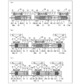
- FIG. 16 is an explanatory diagram showing the configuration of the main body 10b in the in-pipe working device 1 according to the present embodiment, where (a) shows the first state, (b) shows the second state, and (c) shows the third state. Show.
- the main body 10b is provided in the in-pipe working device 1 in place of the main body 10 in the first embodiment.
- the main body 10 b includes connecting members 150, 160, 170, and 180 instead of the connecting members 80, 90, 100, and 110 in the main body 10 of the first embodiment.
- the configuration of the connecting members 50, 60, and 70 is the same as that of the first embodiment.
- the connecting member 150 includes a base portion 150a and an extending portion 151 extending from the base portion 150a to the connecting member 160 side along the axial direction of the main body portion 10b. Further, on the outer peripheral surface of the connecting member 150 in the vicinity of the portion facing the connecting member 160, leg mounting portions 152 for mounting the inspection leg portion 20 are provided at two symmetrical positions with respect to the axial direction of the main body portion 10b. It has been.
- the surface of the connecting member 150 on the side of the connecting member 70 has a substantially cylindrical shape that opens to the side of the connecting member 70 as in the case of the connecting member 80 in the first embodiment (see FIG. 7).
- the surface is an internal gear formed with a tooth surface that meshes with the external gear 22 b of the motor 22.
- the connecting member 160 includes an accommodating portion 161 having an inner diameter slightly larger than the outer diameter of the extending portion 151 for accommodating the extending portion 151 provided in the connecting member 150 on the surface facing the connecting member 150. . Further, on the outer peripheral surface of the connecting member 160 in the vicinity of the portion facing the connecting member 150, leg attaching portions 162 for attaching the inspection leg portions 20 are provided at positions corresponding to the leg attaching portions 152 of the connecting member 150, respectively. Is provided.
- the connecting member 160 includes an accommodating portion 163 having an inner diameter slightly larger than the outer diameter of the extending portion 181 for accommodating the extending portion 181 provided in the connecting member 180 on the surface facing the connecting member 170. ing.
- a spring (second elastic member) 86 is disposed between the connecting member 50 and the connecting member 150 (second stretchable portion 15) along the outer periphery of the extending portion 151. 160 are biased by springs 86 in directions away from each other.
- a spring having a stronger elastic force than the spring 56 is used as the spring 86.
- the connecting member 170 includes a through hole 172 having an inner diameter slightly larger than the outer diameter of the extending portion 181 through which the extending portion 181 included in the connecting member 180 is inserted. Further, on the outer peripheral surface of the connecting member 170 in the vicinity of the portion facing the connecting member 180, leg attaching portions 171 for attaching the positioning leg portions 21 are provided at three locations at equal intervals along the circumferential direction. .
- connection portion (second joint portion 18) between the connection member 160 and the connection member 170 has springs (see FIG. 8A) along the outer peripheral surfaces of both connection members.
- a restoring elastic member 93 is disposed (not shown in FIG. 16).
- the connecting member 180 includes a base portion 180a and an extending portion 181 extending from the base portion 180a to the connecting member 170 side along the axial direction of the main body portion 10b.
- the extending portion 181 includes a body portion 184 provided on the base side (base portion 180a side), a spherical portion 182 that is a curved surface portion provided on the distal end side, and a small diameter portion that connects the body portion 184 and the spherical portion 182. 183.
- leg mounting portions 185 for mounting the positioning leg portions 21 are provided at positions corresponding to the leg mounting portions 171 of the connecting member 170, respectively. Is provided.
- a spring (first elastic member) 113 is disposed between the connecting member 170 and the connecting member 180 (the third elastic part 16) along the outer periphery of the extending part 181. 180 is urged away from each other by a spring 113.
- a spring having substantially the same elastic force as the spring 56 is used as the spring 113.
- the eye nut 114 for attaching the wire end 35b (one end part of the inner wire 31) of the wire cable 12, and the wire cable 11 is attached to the connection member 180 similarly to the connection member 110 in Embodiment 1 ( (See (c) of FIG. 2).
- the positioning leg portions 19 and 21 and the inspection leg portion 20 are contracted to a position close to the main body portion 10b, and the positioning leg portions 19 and 21 and the inspection leg portion 20 are inspected.
- Each connecting rod of the leg portion 20 is configured to be folded on each other.
- the connecting members 50 and 60 can be bent in the axial direction with respect to the connecting member 70 around the spherical portion 54 in the first joint portion 17, and the third joint portion 18.
- the connecting members 170 and 180 can be bent in the axial direction with respect to the connecting member 160 with the spherical portion 182 as an axis.
- the elastic forces of the springs 56 and 113 are set to be substantially the same, and the elastic force of the spring 86 is set stronger than that of the springs 56 and 113. For this reason, in the second state, as shown in FIG. 16B, the first telescopic part 14 and the third telescopic part 16 contract and the positioning leg parts 19 and 21 expand, The expansion / contraction part 15 (interval between the connection member 150 and the connection member 160) is maintained in the extended state, and the inspection leg part 20 remains contracted.
- the extending portion 51 of the connecting member 50 has the spherical portion 54 at the tip, the small diameter portion 53, and a part of the body portion 52 accommodated in the accommodating portion 71 of the connecting member 70.
- drum 52 and the inner wall of the accommodating part 71 interfere, and the bending with respect to the connection member 70 of the connection members 50 and 60 is restrict
- the spherical portion 182 at the tip, the small diameter portion 183, and a part of the body portion 184 are accommodated in the accommodating portion 163 of the connecting member 160.
- drum 184 and the inner wall of the accommodating part 163 interfere, and the bending with respect to the connection members 160 and 170 of the connection member 180 is restrict
- the bending of the connecting members 50 and 60 with respect to the connecting member 70 and the bending of the connecting member 180 with respect to the connecting members 160 and 170 are limited.
- both the first joint portion 17 and the second joint portion 18 can be bent in the first state, and the first joint portion in the second state and the third state.
- the bending of both 17 and the second joint 18 is limited.
- the positioning legs 19 and 21 are extended to limit the positioning of the main body 10b and the bending of the main body 10b (the bending of the first joint 17 and the second joint 18).
- the test leg 20 can be extended in the third state. Therefore, since the inspection leg 20 can be extended in a state where the posture of the main body 10b is more stabilized, the inspection position can be set more accurately.
- the position of the second joint portion 18 is arranged closer to the distal end side of the main body portion 10b than in the first embodiment. Therefore, the operation
- a spherical portion having a substantially spherical curved surface is used as the curved surface portion, and the bending direction is free.
- the curved portion is not limited to a substantially spherical shape and is bent in one direction. It may be a curved surface that enables
- the in-pipe working device is inserted into the pipe from the branch pipe provided in the pipe.
- it may be inserted into the pipe from a small opening formed on the side of the pipe, the tip of a small-diameter pipe, a valve, or the like, and is not limited to the configuration inserted from the branch pipe.
- the present invention can be applied to an in-pipe working apparatus that is inserted into a pipe and inspects the pipe, and can be particularly suitably used for the inspection of existing pipes such as buried pipes.
Landscapes
- Engineering & Computer Science (AREA)
- General Engineering & Computer Science (AREA)
- Mechanical Engineering (AREA)
- Chemical & Material Sciences (AREA)
- Combustion & Propulsion (AREA)
- Health & Medical Sciences (AREA)
- Life Sciences & Earth Sciences (AREA)
- Hydrology & Water Resources (AREA)
- Public Health (AREA)
- Water Supply & Treatment (AREA)
- Instruments For Viewing The Inside Of Hollow Bodies (AREA)
Abstract
【課題】管内作業を容易に行える管内作業装置を提供する。 【解決手段】所定方向に沿って配列された複数の連結部材からなる本体部(10)と、本体部(10)の一部に固定されたワイヤーケーブル(12)と、ワイヤーケーブル(12)の張力を変化させて連結部材間の間隔を変化させることにより前記所定方向と交差する方向に伸縮する伸縮部材(19,20,21)とを備える。
Description
本発明は、管に挿入されて当該管の内部で作業を行う管内作業装置に関するものである。
従来、上下水道管やガス管等の既設管に挿入されて管の内部で作業を行う管内作業装置が知られている。
例えば、特許文献1には、支持リングと、支持リングの前端部および後端部にそれぞれ設けられたソリ状部材とを備え、それら各ソリ状部材を管の内壁に当接させて支持リングを支持させるようにした管内調査装置が開示されている。なお、前端部のソリ状部材は支持リングから前方かつ拡径方向に突出しており、後端部のソリ状部材は支持リングから後方かつ拡径方向に突出している。
しかしながら、上記特許文献1の管内調査装置は、軸方向の長さが長いため、管内調査装置を管内に挿入するためには、管の継手部を解体したり、管に管内調査装置を挿入するための大きな開口を設けたりする必要がある。
このため、検査のための準備に手間とコストがかかり、また検査対象の管による流体輸送を検査前の準備期間から検査後の復旧期間が終わるまで停止させる必要があるので、管を利用している事業者にとって検査に係る負担が非常に大きいという問題がある。
本発明は、上記の問題点に鑑みて成されたものであり、その目的は、管内への挿入および管内での作業を容易に行うことができる管内作業装置を提供することにある。
本発明の一態様にかかる管内作業装置は、管内に挿入されて管内作業を行う管内作業装置であって、所定方向に沿って配列された複数の連結部材からなる本体部と、前記本体部の一部に固定された線状部材と、前記線状部材の張力を変化させて前記連結部材間の間隔を変化させることにより前記所定方向と交差する方向に伸縮する伸縮部材とを備えていることを特徴としている。
上記の構成によれば、線状部材の張力を変化させることにより、伸縮部材を伸縮させることができる。これにより、伸縮部材を収縮させて管内作業装置の外径を小さくすることができるので、管に備えられる分岐管などの小さな開口から管内作業装置を管内に挿入することができる。また、管内作業装置を管に挿入した後、線状部材の張力を変化させることで伸縮部材を伸長させて管内作業を行わせることができる。したがって、従来のように、管の継手部を解体したり、管に管内作業装置を挿入するための大きな開口を設けたりすることなく、分岐管などの小さな開口を利用して管内作業装置を管内に挿入し、管内作業を行うことができるので、管内作業を容易に行うことができる。
また、前記伸縮部材は、前記管の内壁に当接して当該管内作業装置の前記管に対する位置決めを行う位置決め用脚部であってもよい。
上記の構成によれば、管内作業装置を管に挿入した後、線状部材の張力を変化させることで位置決め用脚部を伸長させて管内作業装置の位置決めを行うことができる。
また、前記管の検査を行うための検査装置を備えている構成としてもよい。
上記の構成によれば、従来のように、管の継手部を解体したり、管に管内作業装置を挿入するための大きな開口を設けたりすることなく、管の検査を容易に行うことができる。
また、前記検査装置は、前記伸縮部材に取り付けられていてもよい。
上記の構成によれば、管内作業装置を管に挿入した後、線状部材の張力を変化させることで伸縮部材を伸長させ、検査装置を所定の検査位置に配置することができる。
また、前記線状部材の張力に応じて互いの間隔が変化する前記連結部材同士を遠ざける方向に付勢する第1弾性部材が配置されており、前記線状部材を弛緩させた第1状態では、前記連結部材同士の間隔が前記第1弾性部材の弾性力によって広げられて前記伸縮部材が前記連結部材に近接する位置まで収縮し、前記線状部材に所定値以上の張力を付与した第2状態では、前記連結部材同士の間隔が前記第1状態よりも狭くなって前記伸縮部材が伸長する構成としてもよい。
上記の構成によれば、線状部材の張力を変化させて連結部材同士の間隔を変化させることにより、伸縮部材を収縮状態と伸長状態とに容易に切り替えることができる。
また、前記伸縮部材は、端部同士が互いに回転可能に接続された複数の連結棒からなる第1連結棒群および第2連結棒群を備え、前記各連結棒群を構成する連結棒同士が互いに交互に交差するように配置された可変形状トラス構造を有しており、前記第1連結棒群の一端は互いの間隔が変化する前記連結部材のうちの一方に取り付けられ、前記第2連結棒群の一端は互いの間隔が変化する前記連結部材のうちの他方に取り付けられている構成としてもよい。
上記の構成によれば、線状部材の張力を変化させて連結部材同士の間隔を変化させることにより、伸縮部材を収縮状態と伸長状態とに容易に切り替えることができる。
また、前記第1連結棒群の他端および前記第2連結棒群の他端に取り付けられた先端部材を備え、前記伸縮部材は前記先端部材が前記管の内壁に当接する位置まで伸長し、前記先端部材を前記管の内壁に押し付ける方向に付勢する先端付勢部材を備えている構成としてもよい。
上記の構成によれば、先端付勢部材の付勢力によって先端部材を管の内壁に押し付けることができるので、伸縮部材と管の内壁との当接状態を安定させることができる。
また、前記線状部材の張力を変化させることにより互いの間隔が変化する前記連結部材を複数組備え、複数組の前記連結部材のうちの2組以上に対応する位置にそれぞれ複数の前記位置決め用脚部が設けられている構成としてもよい。
上記の構成によれば、本体部の延伸方向に沿った複数の位置で管内作業装置を支持することができるので、管内作業装置をより安定的に支持することができる。
また、複数組の前記連結部材のうち前記位置決め用脚部が設けられていない組の少なくとも一部の組に対応する位置に、前記線状部材の張力の変化に応じて前記連結部材間の間隔が変化することにより前記所定方向と交差する方向に伸縮する検査用脚部が設けられており、前記検査用脚部に前記管の検査を行うための検査装置が取り付けられている構成としてもよい。
上記の構成によれば、線状部材の張力を変化させることにより、検査装置を管の内壁に近づく方向に移動させることができる。
また、前記位置決め用脚部に対応する組の連結部材同士を遠ざける方向に付勢する第1弾性部材と、前記検査用脚部に対応する組の連結部材同士を遠ざける方向に付勢する第2弾性部材が配置されており、前記第2弾性部材の方が前記第1弾性部材よりも弾性力が強く、前記線状部材を弛緩させた第1状態から前記線状部材に所定値以上の張力を付与した第2状態に切り替えることにより、前記位置決め用脚部が前記管の内壁に当接する位置まで伸長し、前記第2状態から前記線状部材に前記所定値よりも大きい第2所定値以上の張力を付与した第3状態に切り替えることにより、前記検査用脚部が管の検査を行うための所定の検査位置まで伸長する構成としてもよい。
上記の構成によれば、第2状態に切り替えて位置決め用脚部を管の内壁に当接する位置まで伸長させることで本体部の位置決めを行った後、第3状態に切り替えて検査装置を検査位置に配置することができるので、検査装置の位置決めを精度よく行うことができる。
また、前記検査装置を前記所定方向に略平行な回転軸に沿って回転させる駆動部を備えている構成としてもよい。
上記の構成によれば、検査装置によって管における周方向に沿った広範な領域を検査することができる。
また、前記線状部材は、一端側が少なくとも一部の前記連結部材を貫通して前記本体部の一部に固定され、他端側が前記本体部の端部から前記所定方向に露出したインナーワイヤーと、前記本体部の前記端部に固定され、前記インナーワイヤーにおける前記本体部の端部から露出している部分の一部を覆うアウターワイヤーとを備えており、前記インターワイヤーは前記アウターワイヤーに対して長手方向に相対的に移動可能であり、前記インナーワイヤーの張力を変化させることにより、前記連結部材間の間隔が変化する構成としてもよい。
上記の構成によれば、インナーワイヤーの張力を変化させることにより、伸縮部材の伸長状態を容易に制御することができる。
また、本発明の別の態様にかかる管内作業装置は、管内に挿入されて管内作業を行う管内作業装置であって、所定方向に連結された複数の連結部材を備え、複数の前記連結部材には、前記所定方向に延伸する胴体部と前記胴体部の先端に設けられた曲面部とを有する延伸部を備えた連結部材と、前記延伸部の先端を収容する収容部を備えた連結部材とが含まれており、前記曲面部が前記収容部に収容された状態で前記胴体部が前記収容部から離脱し、前記収容部に収容された前記曲面部を軸として前記胴体部が前記所定方向に対して屈曲可能になる第1状態と、前記曲面部と前記胴体部の一部とが前記収容部に収容され、前記胴体部と前記収容部の内壁とが干渉することにより前記延伸部の前記所定方向に対する屈曲が制限される第2状態とに切替可能であることを特徴としている。
上記の構成によれば、第1状態において本体部を軸方向に対して屈曲可能にすることができるので、管に備えられる分岐管などの小さな開口から管内作業装置を管内に容易に挿入することができる。また、第2状態に切り替えることにより本体部の屈曲が制限された状態にすることができるので、管内作業装置を管に挿入した後の管内作業装置の姿勢を安定させることができる。
以上のように、本発明の管内作業装置によれば、線状部材の張力を変化させることにより、伸縮部材を伸縮させることができる。これにより、伸縮部材を収縮させて管内作業装置の外径を小さくすることができるので、管に備えられる分岐管などの小さな開口から管内作業装置を管内に挿入することができる。また、管内作業装置を管に挿入した後、線状部材の張力を変化させることで伸縮部材を伸長させて管内作業を行わせることができる。したがって、従来のように、管の継手部を解体したり、管に管内作業装置を挿入するための大きな開口を設けたりすることなく、分岐管などの小さな開口を利用して管内作業装置を管内に挿入し、管内作業を行うことができるので、管内作業を容易に行うことができる。
〔実施形態1〕
本発明の一実施形態について説明する。
本発明の一実施形態について説明する。
(1-1.管内作業装置1の全体構成)
図1は、本実施形態にかかる管内作業装置1の概略構成を示す説明図である。この図に示すように、管内作業装置1は、管2に設けられた分岐管3から管2の内部に挿入され、管2の内部で所定の作業を行う。
図1は、本実施形態にかかる管内作業装置1の概略構成を示す説明図である。この図に示すように、管内作業装置1は、管2に設けられた分岐管3から管2の内部に挿入され、管2の内部で所定の作業を行う。
なお、本実施形態では管内作業装置1が管2の検査を行う管検査装置である場合の例について説明するが、管内作業装置1の用途はこれに限るものではなく、例えば、管内の清掃を行う管清掃装置、管の補修を行う管補修装置、管内を撮影する撮像装置、管内の物質を採取する管内物質採取装置などに適用することもできる。
管2は、例えば、上下水道管、ガス管などの流体を輸送するための配管である。また、分岐管3は、空気弁などを管2に取り付けるための、管2から分岐した管2よりも小径の分岐管である。なお、本実施形態では、管2の内径が1000mm、分岐管3の内径が75mmである場合の例について説明するが、管2および分岐管3のサイズはこれに限るものではない。
管内作業装置1は、図1に示すように、軸方向(所定方向)に沿って延伸する本体部10と、本体部10の先端に取り付けられたワイヤーケーブル(先端側ケーブル)11と、本体部10の後端側から本体部10の内部に挿入されたワイヤーケーブル(後端側ケーブル、線状部材)12と、本体部10の伸縮操作を行うための操作用治具13とを備えている。ワイヤーケーブル12の一端側は本体部10の内部を軸方向に沿って通って本体部10の先端近傍に取り付けられており、他端側は操作用治具13に取り付けられている。
本体部10は、第1伸縮部14、第2伸縮部15、第3伸縮部16、第1関節部17、第2関節部18、位置決め用脚部(伸縮部材)19,21、検査用脚部(伸縮部材)20、およびモータ(駆動部)22を備えている。
図2の(a)~(c)は、それぞれ、ワイヤーケーブル12の構成、操作用治具13の構成、ワイヤーケーブル12の本体部10に対する接続部の構成を示す説明図である。
図2に示したように、ワイヤーケーブル12は、インナーワイヤー31、アウターワイヤー32、アウターエンド33a,33b、インナー接続部34a,34b、ワイヤーエンド35a,35b、ロックナット36a~36f、および取手部37を備えている。
また、操作用治具13は、ワイヤーケーブル12の延伸方向に沿って延伸した基板40と、基板40から基板40の板面に対して略垂直な方向に突出したアウター取付板41およびU字板42a,42b,42cを備えている。アウター取付板41には、インナーワイヤー31が貫挿される穴(図示せず)が設けられている。また、U字板42a~42cには、基板40から遠い側の端部をU字状に切り欠いた溝部(図示せず)が形成されている。
インナーワイヤー31の一端側はインナー接続部34bでワイヤーエンド35bに固定されており、他端側はインナー接続部34aでワイヤーエンド35aに固定されている。インナーワイヤー31のワイヤーエンド35a,35bに対する固定方法は特に限定されるものではなく、例えばかしめ等の方法を用いることができる。
アウターワイヤー32はインナーワイヤー31の周囲を覆うチューブ状の部材であり、一端側にアウターエンド33bが取り付けられ、他端側にアウターエンド33aが取り付けられている。また、アウターエンド33aにはロックナット36d,36eが取り付けられており、アウターエンド33bにはロックナット36fが取り付けられている。ロックナット36fは、アウターエンド33bを本体部10に取り付けるためのものである。ロックナット36d,36eは、これらロックナット36d,36eによって操作用治具13のアウター取付板41を挟み込むことにより、アウターエンド33aを操作用治具13に取り付けるためのものである。これにより、本体部10と操作用治具13との間ではインナーワイヤー31がアウターワイヤー32に覆われた状態になっている。
アウターワイヤー32の材質は、特に限定されるものではないが、管内作業装置1を管内に挿入するときに延伸方向に対して湾曲可能であり、かつ延伸方向への圧縮荷重に対して変形しにくい材質であることが好ましい。本実施形態では、アウターワイヤー32として、ポリ塩化ビニル(PVC; polyvinyl chloride)製のチューブを用いている。なお、アウターワイヤー32は、内部に鋼線等の補強部材を備えた構成であってもよく、アウターワイヤー32の外周に沿って補強用のスプリング等を備えた構成であってもよい。
インナーワイヤー31の一端側は、アウターワイヤー32における本体部10側の端部から露出しており、図2の(c)に示すように、本体部10の内部を通って、インナーワイヤー31の一端側に取り付けられたワイヤーエンド35bが本体部10の先端側に配置された連結部材110に固定されている。
インナーワイヤー31の他端側は、アウターワイヤー32における操作用治具13側の端部から露出しており、インナーワイヤー31の他端側に取り付けられたワイヤーエンド35aの端部にはロックナット36aにより取手部37が取り付けられている。
これにより、管内作業装置1の操作者が取手部37を持ってワイヤーケーブル12を延伸方向に操作することにより、ワイヤーエンド35aに取り付けられたロックナット36b,36cが操作用治具13のU字板42a~42cのいずれかに引掛けられるようになっている。
また、インナーワイヤー31を引っ張ると、インナーワイヤー31はアウターワイヤー32内をアウターワイヤー32に対して長手方向に相対的に移動し、アウターワイヤー32から本体部10側に露出する部分の長さ、すなわちアウターエンド33bからワイヤーエンド35bまでの長さが変化するようになっている。なお、以下の説明では、ロックナット36b,36cをU字板42aに引掛けた状態を第1状態、U字板42bに引掛けた状態を第2状態、U字板42cに引掛けた状態を第3状態と称する。
インナーワイヤー31の材質は、管内作業装置1を管内に挿入するときに延伸方向に対して湾曲可能であり、かつ延伸方向への引張荷重に対して適度な強度を有する材質であれば特に限定されるものではなく、例えば各種金属材料からなるものを用いることができる。なお、インナーワイヤー31におけるアウターワイヤー32に覆われる部分に、潤滑剤を塗布しておいてもよい。
ワイヤーケーブル(先端側ケーブル)11は、連結部材110の先端側に固定されたアイナット114に取り付けられている。ワイヤーケーブル11は、管2における分岐管3とは異なる分岐部(図示せず)から管2の外部に引き出され、このワイヤーケーブル11を引っ張ることにより管内作業装置1が管2内を移動するようになっている。
(1-2.本体部10の構成)
図3は、本体部10の構成を示す断面図であり、(a)は第1状態、(b)は第2状態、(c)は第3状態を示している。
図3は、本体部10の構成を示す断面図であり、(a)は第1状態、(b)は第2状態、(c)は第3状態を示している。
本体部10は、図1および図3に示したように、第1伸縮部14、第2伸縮部15、第3伸縮部16、第1関節部17、および第2関節部18を備えている。また、第1伸縮部14には周方向に沿って略等間隔で3か所に位置決め用脚部(伸縮部材)19が備えられており、第2伸縮部15には本体部10の中心軸に対して対称な2か所に検査用脚部(伸縮部材)20が備えられており、第3伸縮部16には周方向に沿って略等間隔で3か所に位置決め用脚部(伸縮部材)21が備えられている。
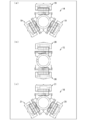
図3の(a)に示したように、第1状態では、第1伸縮部14、第2伸縮部15、および第3伸縮部16はいずれも伸長した状態になり、位置決め用脚部19,21および検査用脚部20は、図4の(a)~(c)に示すように、本体部10に近接する位置まで収縮し、本体部10の外径は分岐管3の内径よりも小さくなる。図4の(a)~(c)は、それぞれ図3の(a)におけるA-A断面、B-B断面、C-C断面の断面図である。
また、第1状態では、第1関節部17および第2関節部18は軸方向に対して屈曲可能な状態になる。これにより、本体部10を分岐管3から管2内に容易に挿入することができる。
図3の(b)に示したように、第2状態では、第1伸縮部14および第3伸縮部16が収縮した状態になる一方、第2伸縮部15は伸長した状態に維持される。これにより、位置決め用脚部19,21が伸長して管2の内壁に当接し、本体部10はこれら各位置決め用脚部によって本体部10の軸心と管2の軸心とが略一致する位置で位置決めされて支持される。また、検査用脚部20は、本体部10に近接する位置まで収縮した状態に維持される。また、第2状態では、第1関節部17は軸方向に対する屈曲が制限された状態(軸方向に屈折しない状態)になり、第2関節部18は軸方向に対して屈曲可能な状態に維持される。
図3の(c)に示したように、第3状態では、第1伸縮部14、第3伸縮部16、および第2伸縮部15がいずれも収縮した状態になる。これにより、位置決め用脚部19,21は伸長して管2の内壁に当接した状態に維持されるとともに、検査用脚部20が伸長して検査用脚部20の先端が所定の検査位置(図3の例では管2に当接する位置)まで伸長する。なお、第3状態では、第1関節部17および第2関節部18は軸方向に対する屈曲が制限された状態(軸方向に屈折しない状態)になる。
図5は、第3状態における本体部10の構成を示す説明図である。この図に示すように、第3状態では、各3本の位置決め用脚部19,21が伸長して管2の内壁に当接し、本体部10の軸心が管2の軸心と略一致するように本体部10が支持される。また、第3状態では、2本の検査用脚部20が伸長し、検査用脚部20の先端に設けられた検査装置(図示せず)が所定の検査位置に配置される。
なお、上記検査装置の構成は特に限定されるものではなく、例えば、過流探傷装置、超音波探傷装置、撮像装置など、管の検査を行うための各種装置を用いることができる。
また、上記所定の検査位置は、検査用脚部20の先端に取り付けられた検査装置(図示せず)を用いて管2の検査を行うための位置であり、検査装置の種類や特性等に応じて設定される。例えば、上記検査位置は、検査装置が管2の内壁に当接する位置であってもよく、管2の内壁の近傍の位置であってもよく、管2の内壁から所定距離だけ離れた位置であってもよい。また、検査用脚部20を省略し、検査装置を本体部10、位置決め用脚部19、あるいは位置決め用脚部21に取り付けてもよい。
また、本実施形態では、位置決め用脚部19,21を周方向に沿ってそれぞれ3本備えているが、位置決め用脚部19,21の本数はこれに限るものではなく、本体部10を安定して支持できる構成であればよい。
また、位置決め用脚部19,21の一方を省略してもよく、位置決め用脚部19,21に加えて他の位置決め用脚部(図示せず)を備えていてもよい。
(1-3.本体部10の構成)
図6は、ワイヤーケーブル12におけるインナーワイヤー31の張力の状態と本体部10の各部の伸縮状態との関係を示す説明図であり、(a)は第1状態、(b)は第2状態、(c)は第3状態を示している。
図6は、ワイヤーケーブル12におけるインナーワイヤー31の張力の状態と本体部10の各部の伸縮状態との関係を示す説明図であり、(a)は第1状態、(b)は第2状態、(c)は第3状態を示している。
図6の(a)~(c)に示したように、本体部10は、軸方向に沿って直列に配置された連結部材50、60、70、80、90、100、および110からなる連結構造を有している。
連結部材50は、ベース部50aと、ベース部50aから本体部10の軸方向に沿って連結部材60側に延伸する延伸部51とを備えている。延伸部51は、根元側(ベース部50a側)に設けられた胴体部52と、先端側に設けられた曲面部である球状部54と、胴体部52と球状部54とを接続する小径部53とを備えている。なお、胴体部52における延伸方向に垂直な方向の外径と球状部54における同方向の外径とは略同一であり、小径部53における上記方向の外径は胴体部52および球状部54の外径よりも小さくなっている。また、連結部材50(ベース部50a)における連結部材60との対向部近傍の外周面には、位置決め用脚部19を取り付けるための脚取付部55が周方向に沿って等間隔で3か所に設けられている。
なお、ベース部50aは必須の構成ではなく、省略してもよい。例えば、図11に示すように、ベース部50aを省略して連結部材50を延伸部51のみからなる構成とし、脚取付部55を延伸部51の胴体部52に設けてもよい。
また、本実施形態では、胴体部52の外径と球状部54の外径とを略同一とし、胴体部52と球状部54との間にそれら両部材よりも外径が小さい小径部53を設けているが、これに限るものではない。例えば、図12に示すように、胴体部52の外径を球状部54の外径よりも小さくし、小径部53を省略してもよい。また、図13に示すように、小径部53を省略するとともに、胴体部52を先端側へ向かうほど外径が小さくなるテーパ形状とし、かつ胴体部52における球状部54との接続部の外径を球状部54の外径よりも小さくしてもよい。
連結部材60は、連結部材50の延伸部51が貫挿される、延伸部51の外径よりも内径がわずかに大きい貫通孔61を備えている。また、連結部材60における連結部材50との対向部近傍の外周面には、連結部材50の各脚取付部55に対応する位置に、位置決め用脚部19を取り付けるための脚取付部62がそれぞれ設けられている。
また、連結部材50と連結部材60との間(第1伸縮部14)には、延伸部51の外周に沿ってバネ(第1弾性部材)56が配置されており、連結部材50と連結部材60とはバネ56によって互いに離間する方向に付勢されている。
連結部材70は、連結部材60との対向面に、連結部材60を貫通した延伸部51を収容するための、延伸部51の外径よりもわずかに大きい内径を有する収容部71を備えている。また、連結部材60と連結部材70との接続部(第1関節部17)には、これら両連結部材の外周面に沿ってバネ(復元用弾性部材)63(図1参照)が配置されている。バネ63は、連結部材60と連結部材70との間に外力が作用していない場合に、これら両連結部材を互いの軸心が略一致する状態で当接させる方向に付勢している。すなわち、バネ63は、連結部材60と連結部材70との間が屈曲した場合に、これら両部材の相対位置(相対角度)を互いの軸心が略一致する初期位置に復元させる復元力を付与している。
なお、連結部材60は必須の構成ではなく、省略してもよい。例えば、図14に示すように、連結部材60を省略し、連結部材50と連結部材70との間における延伸部51の外周に沿ってバネ56を配置してもよい。あるいは、図15に示すように、バネ56を連結部材70における収容部71内(連結部材50の球状部54と収容部71の底面(収容部における連結部材50から遠い側の端部)との間)に配置してもよい。また、連結部材60を省略する場合、脚取付部62を連結部材70に設けてもよい。
また、本実施形態ではバネ63によって上記復元力を付与しているが、これに限るものではない。例えば、連結部材70の収容部71における第1状態において球状部54に当接する部分に周方向に沿ってゴム等の弾性部材を配置し、連結部材50の球状部54に上記弾性部材に係合する溝を設けておき、上記弾性部材によって連結部材50を連結部材70に対して屈曲可能に支持するとともに、外力が加えられたときに復元力が付与される構成としてもよい。
また、連結部材70には、連結部材80,90を本体部10の軸方向に沿って回転駆動するためのモータ(駆動部)22が取り付けられている。
図7は、モータ22と連結部材80との接続部の構成を示す説明図である。この図に示すように、モータ22の駆動軸22aには外歯歯車22bが形成されている。また、連結部材80における連結部材70側の面は連結部材70側に開口した略円筒形状になっており、この円筒形状の内周面はモータ22の外歯歯車22bと噛み合う歯面が形成された内歯歯車になっている。
これにより、モータ22の駆動軸22aが回転駆動されると連結部材80および90(図6に示した第2関節部18から回転接続部18bまでの範囲)が本体部10の軸方向に沿って回転する。
また、連結部材80は、ベース部80aと、ベース部80aから本体部10の軸方向に沿って連結部材90側に延伸する延伸部81とを備えている。延伸部81は、根元側(ベース部80a側)に設けられた胴体部82と、先端側に設けられた曲面部である球状部84と、胴体部82と球状部84とを接続する小径部83とを備えている。なお、胴体部82における延伸方向に垂直な方向の外径と球状部84における同方向の外径とは略同一であり、小径部83における上記方向の外径は胴体部82および球状部84の外径よりも小さくなっている。また、連結部材80における連結部材90との対向部近傍の外周面には、検査用脚部20を取り付けるための脚取付部85が連結部材80の軸に対して対称な2か所に設けられている。
連結部材90は、連結部材80の延伸部81が貫挿される、延伸部81の外径よりも内径がわずかに大きい貫通孔91を備えている。また、連結部材90における連結部材80との対向部近傍の外周面には、連結部材80の各脚取付部85に対応する位置に、検査用脚部20を取り付けるための脚取付部92がそれぞれ設けられている。
また、連結部材80と連結部材90との間(第2伸縮部15)には、延伸部81の外周に沿ってバネ(第2弾性部材)86が配置されており、連結部材80と連結部材90とはバネ86によって互いに離間する方向に付勢されている。なお、本実施形態では、バネ86として、バネ56よりも弾性力が強いバネを用いている。
連結部材100は、連結部材90との対向面に、連結部材90を貫通した延伸部81を収容するための、延伸部81の外径よりもわずかに大きい内径を有する収容部101を備えている。
また、図8の(a)に示すように、連結部材90と連結部材100との接続部(第2関節部18)には、これら両連結部材の外周面に沿ってバネ(復元用弾性部材)93が配置されている。
バネ93は、図8の(b)に示すように、連結部材90,100に螺旋状に巻き付けられる螺旋部93cと、螺旋部93cの両端に形成された接続部93a,93bとを備えている。接続部93a,93bはそれぞれ連結部材90,100の周方向に沿って形成された開口部を有しており、この開口部に連結部材90,100の外周面に形成された突出部94,104を引掛けることにより、バネ93が連結部材90,100に装着される。上記各開口部は、連結部材90,100の周方向に沿って約180°の範囲にわたって形成されている。
これにより、モータ22が駆動軸22aを回転させることにより、連結部材90と連結部材100とが所定の基準位置に対して相対的に±180°の範囲で回転できるようになっている。また、バネ93により、連結部材90と連結部材100とは、これら両連結部材に外力が作用していない場合に貫通孔91と収容部101とが連通する状態(連結部材90の軸心と連結部材100の軸心とが略一致する状態)で当接するように付勢されている。なお、上述したバネ63の構成およびバネ63の連結部材60,70に対する装着方法についても、バネ93の構成およびバネ93の連結部材90,100に対する装着方法と略同様である。
また、連結部材100は、連結部材110との対向面に、連結部材110に備えられる延伸部111を収容するための、延伸部111の外径よりもわずかに大きい内径を有する収容部102を備えている。また、連結部材100における連結部材110との対向部近傍の外周面には、位置決め用脚部21を取り付けるための脚取付部103が周方向に沿って等間隔で3か所に設けられている。
連結部材110は、ベース部110aと、本体部10の軸方向に沿って連結部材100側に延伸する円筒形状の延伸部111とを備えており、延伸部111の一部は連結部材100の収容部102に収容されている。また、連結部材110における連結部材100との対向部近傍の外周面には、連結部材100の各脚取付部103に対応する位置に、位置決め用脚部21を取り付けるための脚取付部112がそれぞれ設けられている。
また、連結部材100と連結部材110との間(第3伸縮部16)には、延伸部111の外周に沿ってバネ(第1弾性部材)113が配置されており、連結部材100と連結部材110とはバネ113によって互いに離間する方向に付勢されている。なお、本実施形態では、バネ113として、バネ56と略同一の弾性力を有するバネを用いている。また、連結部材110には、図2の(c)に示したように、ワイヤーケーブル12のワイヤーエンド35b(インナーワイヤー31の一端部)、およびワイヤーケーブル11を取り付けるためのアイナット114が取り付けられている。
(1-4.位置決め用脚部19,21および検査用脚部20の構成)
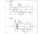
図9は、位置決め用脚部19,21の構成を示す説明図であり、(a)は位置決め用脚部19,21を収縮させた状態の側面図、(b)は位置決め用脚部19,21の上面図(管2の内壁との当接面の図)、(c)は位置決め用脚部19,21を伸長させた状態の側面図である。なお、検査用脚部20の構成は、検査用脚部20の先端部に管2を検査するための検査装置(図示せず)が設けられている以外は位置決め用脚部19,21と略同様である。このため、検査用脚部20の構成の詳細については説明を省略する。
図9は、位置決め用脚部19,21の構成を示す説明図であり、(a)は位置決め用脚部19,21を収縮させた状態の側面図、(b)は位置決め用脚部19,21の上面図(管2の内壁との当接面の図)、(c)は位置決め用脚部19,21を伸長させた状態の側面図である。なお、検査用脚部20の構成は、検査用脚部20の先端部に管2を検査するための検査装置(図示せず)が設けられている以外は位置決め用脚部19,21と略同様である。このため、検査用脚部20の構成の詳細については説明を省略する。
図9の(c)に示すように、位置決め用脚部19,21は、連結棒120,121,122からなる第1連結棒群と、連結棒123,124,125からなる第2連結棒群とを備えている。
位置決め用脚部19を代表に説明すると、連結棒120の一端側は接続部130によって連結部材50の脚取付部55に対して回転可能に取り付けられており、連結棒120の他端側は接続部134によって連結棒121の一端側に互いに回転可能に接続されている。また、連結棒121の他端側は接続部136によって連結棒122の一端側に互いに回転可能に接続されている。また、連結棒122の他端側は、連結棒122および連結棒125を接続するための接続部材143に対して回転可能に接続されている。
また、連結棒123の一端側は接続部131によって連結部材60の脚取付部62に対して回転可能に取り付けられており、連結棒123の他端側は接続部133によって連結棒124の一端側に互いに回転可能に接続されている。また、連結棒124の他端側は接続部137によって連結棒125の一端側に互いに回転可能に接続されている。また、連結棒125の他端側は接続部材143に対して回転可能に接続されている。
また、接続部材143における本体部10の径方向外側には、管2と当接する部材である先端部材142が配置されている。また、先端部材142は位置決め用脚部19,21に対して本体部10の径方向に所定範囲内で平行移動可能になっており、先端部材142と接続部材143との間にはバネ(先端付勢部材)140,141が配置されており、このバネ140,141によって先端部材142は本体部10の径方向外側(当該先端部材142を管の内壁に押し付ける方向)に付勢されている。なお、本実施形態では、バネ140,141によって先端部材142を径方向外側に付勢しているが、これに限らず、例えばゴム等の弾性部材によって付勢してもよい。
また、連結棒120と連結棒123とは略同じ長さを有しており、互いに交差するように配置されるとともに、これら両部材の交差部が接続部132によって互いに回転可能に接続されている。なお、接続部130から接続部132までの距離と接続部131から接続部132までの距離とは略同じ長さに設定されている。
また、連結棒121と連結棒124とは略同じ長さを有しており、互いに交差するように配置されるとともに、これら両部材の交差部が接続部135によって互いに回転可能に接続されている。なお、接続部133から接続部135までの距離と接続部134から接続部135までの距離とは略同じ長さに設定されている。また、連結棒122と連結棒125とは略同じ長さを有している。
また、位置決め用脚部19,21の各連結棒は、第1状態では図9の(a)に示すように互いに折り重なるようにして本体部10の軸心に略平行な状態に配置されるようになっている。
(1-5.本体部10の動作)
(1-5-1.第1状態)
ワイヤーケーブル12が第1状態に設定されている場合、図6の(a)に示したように、連結部材50と連結部材60との間隔(第1伸縮部14の間隔)および連結部材100と連結部材110との間隔(第3伸縮部16の間隔)がバネ56,113の弾性力によって広げられて距離D1になり、連結部材80と連結部材90との間隔(第2伸縮部15の間隔)がバネ86の弾性力によって広げられて距離D3になる。
(1-5-1.第1状態)
ワイヤーケーブル12が第1状態に設定されている場合、図6の(a)に示したように、連結部材50と連結部材60との間隔(第1伸縮部14の間隔)および連結部材100と連結部材110との間隔(第3伸縮部16の間隔)がバネ56,113の弾性力によって広げられて距離D1になり、連結部材80と連結部材90との間隔(第2伸縮部15の間隔)がバネ86の弾性力によって広げられて距離D3になる。
その結果、位置決め用脚部19,21および検査用脚部20は、図6の(a)および図9の(a)に示したように、本体部10に近接する位置まで収縮し、位置決め用脚部19,21および検査用脚部20の各連結棒は互いに折り重なる構成になる。これにより、第1状態では、図4の(a)~(c)に示したように、位置決め用脚部19,21および検査用脚部20が収縮して本体部10の外径が分岐管3の内径よりも小さくなり、分岐管3を介して管2内に本体部10を挿入可能になる。
図10の(a)は、第1状態における第1伸縮部14の状態をより詳細に示した説明図である。この図に示すように、第1状態では、連結部材50における延伸部51は、先端の球状部54が連結部材70の収容部71に収容され、小径部53が連結部材60と連結部材70との接続部である第1関節部17に配置される。
これにより、連結部材50,60は、球状部54を軸として連結部材70に対して軸方向に屈曲可能になる。なお、第1関節部17にはバネ63が備えられており、このバネ63によって連結部材50,60と連結部材70とは互いの軸方向が一致する方向に付勢されている。これにより、連結部材50,60は、バネ63の弾性力に打ち勝つ外力が作用した場合に連結部材70に対して屈曲する。また、連結部材50,60が連結部材70に対して屈曲した場合であっても、バネ63が設けられていることによってこれら各連結部材が完全に離脱せず、外力が除去された場合に元の位置に容易に復元するようになっている。
同様に、第1状態では、図6の(a)に示したように、連結部材80における延伸部81は、先端の球状部84が連結部材100の収容部101に収容され、小径部83が連結部材90と連結部材100との接続部である第2関節部18に配置される。
これにより、連結部材80,90は、球状部84を軸として連結部材100に対して軸方向に屈曲可能になる。また、第2関節部18にはバネ93が備えられており、このバネ93によって連結部材80,90と連結部材100とは互いの軸方向が一致する方向に付勢されている。これにより、連結部材80,90は、バネ93の弾性力に打ち勝つ外力が作用した場合に連結部材100に対して屈曲する。また、連結部材80,90が連結部材100に対して屈曲した場合であっても、バネ93が設けられていることによってこれら各連結部材が完全に離脱せず、外力が除去された場合に元の位置に容易に復元するようになっている。なお、本実施形態ではバネ93によって上記復元力を付与しているが、これに限るものではなく、例えば上述したバネ63に代えてゴム等の弾性部材を用いる構成と同様、ゴム等の弾性部材によって復元力を付与する構成としてもよい。
(1-5-2.第2状態)
ワイヤーケーブル12が第1状態から第2状態に切り替えられると、インナーワイヤー31の張力がバネ56,113の弾性力に打ち勝って連結部材50と連結部材60との間隔(第1伸縮部14の間隔)および連結部材100と連結部材110との間隔(第3伸縮部16の間隔)が距離D1より狭い距離D2になる。これにより、図6の(b)および図9の(c)に示したように、位置決め用脚部19,21は管2の内壁に当接する位置まで伸長する。
ワイヤーケーブル12が第1状態から第2状態に切り替えられると、インナーワイヤー31の張力がバネ56,113の弾性力に打ち勝って連結部材50と連結部材60との間隔(第1伸縮部14の間隔)および連結部材100と連結部材110との間隔(第3伸縮部16の間隔)が距離D1より狭い距離D2になる。これにより、図6の(b)および図9の(c)に示したように、位置決め用脚部19,21は管2の内壁に当接する位置まで伸長する。
また、本実施形態では、上述したように、バネ56,113の弾性力を略同一とし、バネ86の弾性力をバネ56,113よりも強く設定している。これにより、第2状態では、図6の(b)に示したように、第1伸縮部14と第3伸縮部16とが収縮して位置決め用脚部19,21が伸長する一方、第2伸縮部15(連結部材80と連結部材90との間隔)は伸長した状態に維持され、検査用脚部20は収縮したままになる。
図10の(b)は、第2状態における第1伸縮部14の状態をより詳細に示した説明図である。この図に示すように、第2状態では、連結部材50における延伸部51は、先端の球状部54と、小径部53と、胴体部52の一部とが連結部材70の収容部71に収容される。これにより、胴体部52と収容部71の内壁とが干渉し、連結部材50,60の連結部材70に対する屈曲が制限される。
なお、第2状態では、第1状態と同様、連結部材80,90(第2伸縮部15)は、球状部84を軸として連結部材100に対して軸方向に屈曲可能な状態に維持される。
(1-5-3.第3状態)
ワイヤーケーブル12が第2状態から第3状態に切り替えられると、図6の(c)に示したように、インナーワイヤー31の張力がバネ86の弾性力に打ち勝って連結部材80と連結部材90との間隔(第2伸縮部15の間隔)が第1状態および第2状態における距離D3よりも狭い距離D4になり、検査用脚部20が所定の検査位置まで伸長する。
ワイヤーケーブル12が第2状態から第3状態に切り替えられると、図6の(c)に示したように、インナーワイヤー31の張力がバネ86の弾性力に打ち勝って連結部材80と連結部材90との間隔(第2伸縮部15の間隔)が第1状態および第2状態における距離D3よりも狭い距離D4になり、検査用脚部20が所定の検査位置まで伸長する。
また、第3状態では、図6の(c)に示したように、連結部材80における延伸部81は、先端の球状部84と、小径部83と、胴体部82の一部とが連結部材100の収容部101に収容される。これにより、胴体部82と収容部101の内壁とが干渉し、連結部材80,90の連結部材100に対する屈曲が制限される。
(1-6.実施形態1のまとめ)
以上のように、本実施形態にかかる管内作業装置1は、軸方向に沿って配列された複数の連結部材(50,60,70,80,90,100,110)からなる本体部10と、少なくとも一部の上記連結部材(50,60,70,80,90,100)を貫通して上記本体部10の連結部材110に固定されたワイヤーケーブル12と、ワイヤーケーブル12の張力を変化させて連結部材50-60間および連結部材100-110間の間隔を変化させることにより上記軸方向と交差する方向に伸縮する複数の位置決め用脚部19,21とを備えている。
以上のように、本実施形態にかかる管内作業装置1は、軸方向に沿って配列された複数の連結部材(50,60,70,80,90,100,110)からなる本体部10と、少なくとも一部の上記連結部材(50,60,70,80,90,100)を貫通して上記本体部10の連結部材110に固定されたワイヤーケーブル12と、ワイヤーケーブル12の張力を変化させて連結部材50-60間および連結部材100-110間の間隔を変化させることにより上記軸方向と交差する方向に伸縮する複数の位置決め用脚部19,21とを備えている。
これにより、ワイヤーケーブル12の張力を変化させることで、位置決め用脚部19,21を収縮させた状態と伸長させた状態とに切り替えることができる。このため、位置決め用脚部19,21を収縮させて管内作業装置1の外径を小さくすることができるので、管2に備えられる分岐管3から管内作業装置1を管2内に挿入することができる。また、管内作業装置1を管2に挿入した後、ワイヤーケーブル12の張力を変化させることで位置決め用脚部19,21を伸長させて管内作業装置1の位置決めを行うことができる。したがって、従来の管内作業装置のように、管の継手部を解体したり、管に管内作業装置を挿入するための大きな開口を設けたりする必要がないので、管の検査を容易に行うことができる。
また、連結部材50,80は軸方向に延伸する延伸部51,81を備え、連結部材60,90は延伸部51,81が貫通する貫通孔61,91を備えており、延伸部51,81は、根元側に設けられた胴体部52,82と、先端側に設けられた球状部54,84とを備え、連結部材60,90に対して連結部材50,80とは反対側に隣接する連結部材70,100は、延伸部51,81の先端を収容する収容部71,101を備えており、ワイヤーケーブル12を弛緩させた第1状態では、球状部54,84が収容部71,101に収容された状態で胴体部52,82が収容部71,101から離脱し、収容部71,101に収容された球状部54,84を軸として延伸部51,81が軸方向に対して屈曲可能であり、ワイヤーケーブル12に所定値以上の張力を付与した第2状態では、球状部54,84と胴体部52,82の一部とが収容部71,101に収容され、胴体部52,82と収容部71,101の内壁とが干渉することにより延伸部51,81の軸方向に対する屈曲が制限される。
これにより、第1状態において本体部10を軸方向に対して屈曲可能にすることができることができるので、管2に備えられる分岐管3から管内作業装置1を管2内に容易に挿入することができる。また、第2状態に切り替えることにより本体部10の第1関節部17の屈曲が制限された状態にすることができ、第3状態に切り替えることにより第2関節部18の屈曲が制限された状態にすることができるので、管内作業装置1を管に挿入した後の管内作業装置1の位置決めを精度よく行うとともに、管内作業装置1の姿勢を安定させることができる。
なお、本実施形態では、連結部材50の延伸部51、および連結部材80の延伸部81が同方向に延伸するように配置された構成について説明したが、これに限らず、上記両延伸部が互いに反対方向(互いに向き合う方向、または互いに反対側に延伸する方向)に配置されていてもよい。
また、本実施形態では、第1伸縮部14、第2伸縮部15、および第3伸縮部16の3つの伸縮部を備えた構成について説明したが、これに限るものではなく、伸縮部の数は検査対象とする管2のサイズや分岐管3のサイズ等に応じて適宜変更してもよい。
また、本実施形態では、本体部10を軸方向に対して屈曲可能な関節部を2か所(第1関節部17および第2関節部18)に設けた構成について説明したが、関節部の数は検査対象とする管2のサイズや分岐管3のサイズ等に応じて適宜変更してもよい。
また、本実施形態では、本体部10の延伸方向に沿った2箇所(第1伸縮部14および第3伸縮部16)に位置決め用脚部19,21を備え、1箇所(第2伸縮部15)に検査用脚部20を備えている構成について説明したが、これに限るものではなく、本体部10の伸縮部のうちの少なくとも1箇所に連結部材間の間隔の変化に応じて伸縮する脚部が設けられていればよい。例えば、位置決め用脚部19,21の一方または両方に代えて、気体または液体を注入することによって膨張するバルーン(膨張体;図示せず)を配置し、管内作業装置1を管2内に挿入した後に上記バルーンを管2の内壁に当接するまで膨らませることにより、管内作業装置1の管2に対する位置決めおよび支持を行うようにしてもよい。
また、本実施形態では、第1伸縮部14、第2伸縮部15、および第3伸縮部16に備えられる弾性部材としてバネ56,86,113を用いているが、これに限らず、ゴム等の他の弾性部材を用いてもよい。
〔実施形態2〕
本発明の他の実施形態について説明する。なお、説明の便宜上、実施形態1と同じ機能を有する部材については同じ符号を付し、その説明を省略する。
本発明の他の実施形態について説明する。なお、説明の便宜上、実施形態1と同じ機能を有する部材については同じ符号を付し、その説明を省略する。
実施形態1では、第1状態では第1関節部17および第2関節部18が共に屈曲可能になり、第2状態では第1関節部17の屈曲が制限される一方、第2関節部18が屈曲可能な状態に維持され、第3状態では第1関節部17および第2関節部18の屈曲が共に制限される構成について説明した。これに対して、本実施形態では、第1状態では第1関節部17および第2関節部18が共に屈曲可能になり、第2状態および第3状態では第1関節部17および第2関節部18の屈曲が共に制限される構成について説明する。
(2-1.本体部10bの構成)
図16は、本実施形態にかかる管内作業装置1における本体部10bの構成を示す説明図であり、(a)は第1状態、(b)は第2状態、(c)は第3状態を示している。なお、本体部10bは、実施形態1における本体部10に代えて管内作業装置1に備えられるものである。
図16は、本実施形態にかかる管内作業装置1における本体部10bの構成を示す説明図であり、(a)は第1状態、(b)は第2状態、(c)は第3状態を示している。なお、本体部10bは、実施形態1における本体部10に代えて管内作業装置1に備えられるものである。
図16に示すように、本体部10bは、実施形態1の本体部10における連結部材80、90、100、および110に代えて、連結部材150、160、170、および180を備えている。連結部材50、60、および70の構成は実施形態1と同様である。
連結部材150は、ベース部150aと、ベース部150aから本体部10bの軸方向に沿って連結部材160側に延伸する延伸部151とを備えている。また、連結部材150における連結部材160との対向部近傍の外周面には、検査用脚部20を取り付けるための脚取付部152が本体部10bの軸方向に対して対称な2か所に設けられている。
また、連結部材150における連結部材70側の面は、実施形態1における連結部材80と同様(図7参照)、連結部材70側に開口した略円筒形状になっており、この円筒形状の内周面はモータ22の外歯歯車22bと噛み合う歯面が形成された内歯歯車になっている。これにより、モータ22の駆動軸22aが回転駆動されると連結部材150および160(図16に示した第2関節部18から回転接続部18bまでの範囲)が本体部10bの軸方向に沿って回転する。
連結部材160は、連結部材150との対向面に、連結部材150に備えられる延伸部151を収容するための、延伸部151の外径よりもわずかに大きい内径を有する収容部161を備えている。また、連結部材160における連結部材150との対向部近傍の外周面には、連結部材150の各脚取付部152に対応する位置に、検査用脚部20を取り付けるための脚取付部162がそれぞれ設けられている。
また、連結部材160は、連結部材170との対向面に、連結部材180に備えられる延伸部181を収容するための、延伸部181の外径よりもわずかに大きい内径を有する収容部163を備えている。
また、連結部材50と連結部材150との間(第2伸縮部15)には、延伸部151の外周に沿ってバネ(第2弾性部材)86が配置されており、連結部材150と連結部材160とはバネ86によって互いに離間する方向に付勢されている。なお、本実施形態では、バネ86として、バネ56よりも弾性力が強いバネを用いている。
連結部材170は、連結部材180に備えられる延伸部181が貫挿される、延伸部181の外径よりも内径がわずかに大きい貫通孔172を備えている。また、連結部材170における連結部材180との対向部近傍の外周面には、位置決め用脚部21を取り付けるための脚取付部171が周方向に沿って等間隔で3か所に設けられている。
また、連結部材160と連結部材170との接続部(第2関節部18)には、実施形態1と同様(図8の(a)参照)、これら両連結部材の外周面に沿ってバネ(復元用弾性部材)93が配置されている(図16では図示せず)。
連結部材180は、ベース部180aと、ベース部180aから本体部10bの軸方向に沿って連結部材170側に延伸する延伸部181とを備えている。延伸部181は、根元側(ベース部180a側)に設けられた胴体部184と、先端側に設けられた曲面部である球状部182と、胴体部184と球状部182とを接続する小径部183とを備えている。なお、胴体部184における延伸方向に垂直な方向の外径と球状部182における同方向の外径とは略同一であり、小径部183における上記方向の外径は胴体部184および球状部182の外径よりも小さくなっている。また、連結部材180における連結部材170との対向部近傍の外周面には、連結部材170の各脚取付部171に対応する位置に、位置決め用脚部21を取り付けるための脚取付部185がそれぞれ設けられている。
また、連結部材170と連結部材180との間(第3伸縮部16)には、延伸部181の外周に沿ってバネ(第1弾性部材)113が配置されており、連結部材170と連結部材180とはバネ113によって互いに離間する方向に付勢されている。なお、本実施形態では、バネ113として、バネ56と略同一の弾性力を有するバネを用いている。また、連結部材180には、実施形態1における連結部材110と同様、ワイヤーケーブル12のワイヤーエンド35b(インナーワイヤー31の一端部)、およびワイヤーケーブル11を取り付けるためのアイナット114が取り付けられている(図2の(c)参照)。
(2-2.本体部10bの動作)
(2-2-1.第1状態)
ワイヤーケーブル12が第1状態に設定されている場合、図16の(a)に示したように、連結部材50と連結部材60との間隔(第1伸縮部14の間隔)および連結部材170と連結部材180との間隔(第3伸縮部16の間隔)がバネ56,113の弾性力によって広げられて距離D1になり、連結部材150と連結部材160との間隔(第2伸縮部15の間隔)がバネ86の弾性力によって広げられて距離D3になる。
(2-2-1.第1状態)
ワイヤーケーブル12が第1状態に設定されている場合、図16の(a)に示したように、連結部材50と連結部材60との間隔(第1伸縮部14の間隔)および連結部材170と連結部材180との間隔(第3伸縮部16の間隔)がバネ56,113の弾性力によって広げられて距離D1になり、連結部材150と連結部材160との間隔(第2伸縮部15の間隔)がバネ86の弾性力によって広げられて距離D3になる。
その結果、位置決め用脚部19,21および検査用脚部20は、図16の(a)に示したように、本体部10bに近接する位置まで収縮し、位置決め用脚部19,21および検査用脚部20の各連結棒は互いに折り重なる構成になる。これにより、第1状態では、位置決め用脚部19,21および検査用脚部20が収縮して本体部10bの外径が分岐管3の内径よりも小さくなり、分岐管3を介して管2内に本体部10bを挿入可能になる。
また、第1状態では、実施形態1と同様、第1関節部17において連結部材50,60が球状部54を軸として連結部材70に対して軸方向に屈曲可能になり、第3関節部18において連結部材170,180が球状部182を軸として連結部材160に対して軸方向に屈曲可能になる。
(2-2-2.第2状態)
ワイヤーケーブル12が第1状態から第2状態に切り替えられると、インナーワイヤー31の張力がバネ56,113の弾性力に打ち勝って連結部材50と連結部材60との間隔(第1伸縮部14の間隔)および連結部材170と連結部材180との間隔(第3伸縮部16の間隔)が距離D1より狭い距離D2になる。これにより、図16の(b)に示したように、位置決め用脚部19,21は管2の内壁に当接する位置まで伸長する。
ワイヤーケーブル12が第1状態から第2状態に切り替えられると、インナーワイヤー31の張力がバネ56,113の弾性力に打ち勝って連結部材50と連結部材60との間隔(第1伸縮部14の間隔)および連結部材170と連結部材180との間隔(第3伸縮部16の間隔)が距離D1より狭い距離D2になる。これにより、図16の(b)に示したように、位置決め用脚部19,21は管2の内壁に当接する位置まで伸長する。
なお、本実施形態では、バネ56,113の弾性力を略同一とし、バネ86の弾性力をバネ56,113よりも強く設定している。このため、第2状態では、図16の(b)に示したように、第1伸縮部14と第3伸縮部16とが収縮して位置決め用脚部19,21が伸長する一方、第2伸縮部15(連結部材150と連結部材160との間隔)は伸長した状態に維持され、検査用脚部20は収縮したままになる。
また、第2状態では、連結部材50における延伸部51は、先端の球状部54と、小径部53と、胴体部52の一部とが連結部材70の収容部71に収容される。これにより、胴体部52と収容部71の内壁とが干渉し、連結部材50,60の連結部材70に対する屈曲が制限される。
同様に、第2状態では、連結部材180における延伸部181は、先端の球状部182と、小径部183と、胴体部184の一部とが連結部材160の収容部163に収容される。これにより、胴体部184と収容部163の内壁とが干渉し、連結部材180の連結部材160,170に対する屈曲が制限される。
(2-2-3.第3状態)
ワイヤーケーブル12が第2状態から第3状態に切り替えられると、図16の(c)に示したように、インナーワイヤー31の張力がバネ86の弾性力に打ち勝って連結部材150と連結部材160との間隔(第2伸縮部15の間隔)が第1状態および第2状態における距離D3よりも狭い距離D4になり、検査用脚部20が所定の検査位置まで伸長する。
ワイヤーケーブル12が第2状態から第3状態に切り替えられると、図16の(c)に示したように、インナーワイヤー31の張力がバネ86の弾性力に打ち勝って連結部材150と連結部材160との間隔(第2伸縮部15の間隔)が第1状態および第2状態における距離D3よりも狭い距離D4になり、検査用脚部20が所定の検査位置まで伸長する。
なお、第3状態では、第2状態と同様、連結部材50,60の連結部材70に対する屈曲、および連結部材180の連結部材160,170に対する屈曲は制限される。
(2-3.実施形態2のまとめ)
以上のように、本実施形態にかかる管内作業装置1では、第1状態では第1関節部17および第2関節部18が共に屈曲可能になり、第2状態および第3状態では第1関節部17および第2関節部18の屈曲が共に制限される。
以上のように、本実施形態にかかる管内作業装置1では、第1状態では第1関節部17および第2関節部18が共に屈曲可能になり、第2状態および第3状態では第1関節部17および第2関節部18の屈曲が共に制限される。
これにより、第2状態において位置決め用脚部19,21を伸長させて本体部10bの位置決め、および本体部10bの屈曲の制限(第1関節部17および第2関節部18の屈曲の制限)を行った後、第3状態において検査用脚部20を伸長させることができる。したがって、本体部10bの姿勢をより安定させた状態で検査用脚部20を伸長させることができるので、検査位置をより正確に設定することができる。
また、本実施形態では、第2関節部18の位置を実施形態1よりも本体部10bの先端側に配置している。これにより、本体部10bを管2に挿入する作業をより容易に行うことができる。
なお、上記2つの実施形態では、曲面部として略球状の曲面を有する球状部を用い、屈曲の方向を自在にしたものを記載したが、略球状に限られるものではなく、一方向への屈曲を可能とするような曲面であってもよい。
また、上記2つの実施形態では、管に備えられる分岐管から管内作業装置を管内に挿入する例を記載したが、本発明の管内作業装置は対象となる管の直径よりも小さな開口から挿入できればよく、管側面に形成した小さな開口や、小径管の先端や、弁などから管内に挿入してもよく、分岐管から挿入する構成に限られるものではない。
本発明は、上述した各実施形態に限定されるものではなく、請求項に示した範囲で種々の変更が可能であり、異なる実施形態にそれぞれ開示された技術的手段を適宜組み合わせて得られる実施形態についても本発明の技術的範囲に含まれる。さらに、各実施形態にそれぞれ開示された技術的手段を組み合わせることにより、新しい技術的特徴を形成することもできる。
本発明は、管に挿入されて当該管の検査を行う管内作業装置に適用可能であり、埋設管等の既設管の検査に特に好適に利用できる。
1 管内作業装置
2 管
3 分岐管
10 本体部
11 ワイヤーケーブル
12 ワイヤーケーブル(線状部材)
13 操作用治具
14 第1伸縮部
15 第2伸縮部
16 第3伸縮部
17 第1関節部
18 第2関節部
19,21 位置決め用脚部(伸縮部材)
20 検査用脚部(伸縮部材)
22 モータ(駆動部)
31 インナーワイヤー(線状部材)
32 アウターワイヤー
50,60,70,80,90,100,110,150,160,170,180 連結部材
51,81,181 延伸部
52,82,184 胴体部
53,83,183 小径部
54,84,182 球状部(曲面部)
55,62,85,92,103,112,152,162,171,185 脚取付部
56,113 バネ(第1弾性部材)
61,91,172 貫通孔
63,93 バネ(復元用弾性部材)
71,101,163 収容部
86 バネ(第2弾性部材)
102,161 収容部
111,151 延伸部
120~122 連結棒(第1連結棒群)
123~125 連結棒(第2連結棒群)
130~139 接続部
140,141 バネ(先端付勢部材)
142 先端部材
2 管
3 分岐管
10 本体部
11 ワイヤーケーブル
12 ワイヤーケーブル(線状部材)
13 操作用治具
14 第1伸縮部
15 第2伸縮部
16 第3伸縮部
17 第1関節部
18 第2関節部
19,21 位置決め用脚部(伸縮部材)
20 検査用脚部(伸縮部材)
22 モータ(駆動部)
31 インナーワイヤー(線状部材)
32 アウターワイヤー
50,60,70,80,90,100,110,150,160,170,180 連結部材
51,81,181 延伸部
52,82,184 胴体部
53,83,183 小径部
54,84,182 球状部(曲面部)
55,62,85,92,103,112,152,162,171,185 脚取付部
56,113 バネ(第1弾性部材)
61,91,172 貫通孔
63,93 バネ(復元用弾性部材)
71,101,163 収容部
86 バネ(第2弾性部材)
102,161 収容部
111,151 延伸部
120~122 連結棒(第1連結棒群)
123~125 連結棒(第2連結棒群)
130~139 接続部
140,141 バネ(先端付勢部材)
142 先端部材
Claims (14)
- 管内に挿入されて管内作業を行う管内作業装置であって、
所定方向に沿って配列された複数の連結部材からなる本体部と、
前記本体部の一部に固定された線状部材と、
前記線状部材の張力を変化させて前記連結部材間の間隔を変化させることにより前記所定方向と交差する方向に伸縮する伸縮部材とを備えていることを特徴とする管内作業装置。 - 前記伸縮部材は、前記管の内壁に当接して当該管内作業装置の前記管に対する位置決めを行う位置決め用脚部であることを特徴とする請求項1に記載の管内作業装置。
- 前記管の検査を行うための検査装置を備えていることを特徴とする請求項1または2に記載の管内作業装置。
- 前記検査装置は、前記伸縮部材に取り付けられていることを特徴とする請求項3に記載の管内作業装置。
- 前記線状部材の張力に応じて互いの間隔が変化する前記連結部材同士を遠ざける方向に付勢する第1弾性部材が配置されており、
前記線状部材を弛緩させた第1状態では、前記連結部材同士の間隔が前記第1弾性部材の弾性力によって広げられて前記伸縮部材が前記連結部材に近接する位置まで収縮し、
前記線状部材に所定値以上の張力を付与した第2状態では、前記連結部材同士の間隔が前記第1状態よりも狭くなって前記伸縮部材が伸長することを特徴とする請求項1から4のいずれか1項に記載の管内作業装置。 - 前記伸縮部材は、端部同士が互いに回転可能に接続された複数の連結棒からなる第1連結棒群および第2連結棒群を備え、前記各連結棒群を構成する連結棒同士が互いに交互に交差するように配置された可変形状トラス構造を有しており、
前記第1連結棒群の一端は互いの間隔が変化する前記連結部材のうちの一方に取り付けられ、前記第2連結棒群の一端は互いの間隔が変化する前記連結部材のうちの他方に取り付けられていることを特徴とする請求項1から5のいずれか1項に記載の管内作業装置。 - 前記第1連結棒群の他端および前記第2連結棒群の他端に取り付けられた先端部材を備え、
前記伸縮部材は前記先端部材が前記管の内壁に当接する位置まで伸長し、
前記先端部材を前記管の内壁に押し付ける方向に付勢する先端付勢部材を備えていることを特徴とする請求項1から6のいずれか1項に記載の管内作業装置。 - 前記線状部材の張力を変化させることにより互いの間隔が変化する前記連結部材を複数組備え、
複数組の前記連結部材のうちの2組以上に対応する位置にそれぞれ複数の前記位置決め用脚部が設けられていることを特徴とする請求項2に記載の管内作業装置。 - 複数組の前記連結部材のうち前記位置決め用脚部が設けられていない組の少なくとも一部の組に対応する位置に、前記線状部材の張力の変化に応じて前記連結部材間の間隔が変化することにより前記所定方向と交差する方向に伸縮する検査用脚部が設けられており、
前記検査用脚部に前記管の検査を行うための検査装置が取り付けられていることを特徴とする請求項8に記載の管内作業装置。 - 前記位置決め用脚部に対応する組の連結部材同士を遠ざける方向に付勢する第1弾性部材と、前記検査用脚部に対応する組の連結部材同士を遠ざける方向に付勢する第2弾性部材が配置されており、
前記第2弾性部材の方が前記第1弾性部材よりも弾性力が強く、
前記線状部材を弛緩させた第1状態から前記線状部材に所定値以上の張力を付与した第2状態に切り替えることにより、前記位置決め用脚部が前記管の内壁に当接する位置まで伸長し、
前記第2状態から前記線状部材に前記所定値よりも大きい第2所定値以上の張力を付与した第3状態に切り替えることにより、前記検査用脚部が管の検査を行うための所定の検査位置まで伸長することを特徴とする請求項9に記載の管内作業装置。 - 前記検査装置を前記所定方向に略平行な回転軸に沿って回転させる駆動部を備えていることを特徴とする請求項3、4、9、10のいずれか1項に記載の管内作業装置。
- 前記線状部材は、
一端側が少なくとも一部の前記連結部材を貫通して前記本体部の一部に固定され、他端側が前記本体部の端部から前記所定方向に露出したインナーワイヤーと、
前記本体部の前記端部に固定され、前記インナーワイヤーにおける前記本体部の端部から露出している部分の一部を覆うアウターワイヤーとを備えており、
前記インターワイヤーは前記アウターワイヤーに対して長手方向に相対的に移動可能であり、前記インナーワイヤーの張力を変化させることにより、前記連結部材間の間隔が変化することを特徴とする請求項1から11のいずれか1項に記載の管内作業装置。 - 複数の前記連結部材には、前記所定方向に延伸する胴体部と前記胴体部の先端に設けられた曲面部とを有する延伸部を備えた連結部材と、前記延伸部の先端を収容する収容部を備えた連結部材とが含まれており、
前記線状部材を弛緩させた第1状態では、前記曲面部が前記収容部に収容された状態で前記胴体部が前記収容部から離脱し、前記収容部に収容された前記曲面部を軸として前記胴体部が前記所定方向に対して屈曲可能になり、
前記線状部材に所定値以上の張力を付与した第2状態では、前記曲面部と前記胴体部の一部とが前記収容部に収容され、前記胴体部と前記収容部の内壁とが干渉することにより前記延伸部の前記所定方向に対する屈曲が制限されることを特徴とする請求項1から12のいずれか1項に記載の管内作業装置。 - 管内に挿入されて管内作業を行う管内作業装置であって、
所定方向に連結された複数の連結部材を備え、複数の前記連結部材には、前記所定方向に延伸する胴体部と前記胴体部の先端に設けられた曲面部とを有する延伸部を備えた連結部材と、前記延伸部の先端を収容する収容部を備えた連結部材とが含まれており、前記曲面部が前記収容部に収容された状態で前記胴体部が前記収容部から離脱し、前記収容部に収容された前記曲面部を軸として前記胴体部が前記所定方向に対して屈曲可能になる第1状態と、前記曲面部と前記胴体部の一部とが前記収容部に収容され、前記胴体部と前記収容部の内壁とが干渉することにより前記延伸部の前記所定方向に対する屈曲が制限される第2状態とに切替可能であることを特徴とする管内作業装置。
Applications Claiming Priority (4)
| Application Number | Priority Date | Filing Date | Title |
|---|---|---|---|
| JP2014-263645 | 2014-12-25 | ||
| JP2014263645A JP6570247B2 (ja) | 2014-12-25 | 2014-12-25 | 管内作業装置 |
| JP2014-263646 | 2014-12-25 | ||
| JP2014263646A JP6335115B2 (ja) | 2014-12-25 | 2014-12-25 | 連結構造および管内作業装置 |
Publications (1)
| Publication Number | Publication Date |
|---|---|
| WO2016104343A1 true WO2016104343A1 (ja) | 2016-06-30 |
Family
ID=56150363
Family Applications (1)
| Application Number | Title | Priority Date | Filing Date |
|---|---|---|---|
| PCT/JP2015/085437 Ceased WO2016104343A1 (ja) | 2014-12-25 | 2015-12-18 | 管内作業装置 |
Country Status (1)
| Country | Link |
|---|---|
| WO (1) | WO2016104343A1 (ja) |
Cited By (1)
| Publication number | Priority date | Publication date | Assignee | Title |
|---|---|---|---|---|
| CN108253222A (zh) * | 2018-01-12 | 2018-07-06 | 李嘉炜 | 一种市政用天然气管道检漏修补装置 |
Citations (5)
| Publication number | Priority date | Publication date | Assignee | Title |
|---|---|---|---|---|
| JPS58219401A (ja) * | 1982-06-15 | 1983-12-20 | Kubota Ltd | 既設管の管内調査方法 |
| JPH08133073A (ja) * | 1994-11-11 | 1996-05-28 | Olympus Optical Co Ltd | 管内走行装置 |
| JP2000343124A (ja) * | 1999-04-01 | 2000-12-12 | Kyoshin Kogyo Kk | ヘアピン管の局部変形修正具 |
| JP2001128835A (ja) * | 1999-11-05 | 2001-05-15 | Fairyland:Kk | ワイヤー状塑性体とこれを使用した製品 |
| JP2007263578A (ja) * | 2006-03-27 | 2007-10-11 | Jfe Engineering Kk | 管内検査装置 |
-
2015
- 2015-12-18 WO PCT/JP2015/085437 patent/WO2016104343A1/ja not_active Ceased
Patent Citations (5)
| Publication number | Priority date | Publication date | Assignee | Title |
|---|---|---|---|---|
| JPS58219401A (ja) * | 1982-06-15 | 1983-12-20 | Kubota Ltd | 既設管の管内調査方法 |
| JPH08133073A (ja) * | 1994-11-11 | 1996-05-28 | Olympus Optical Co Ltd | 管内走行装置 |
| JP2000343124A (ja) * | 1999-04-01 | 2000-12-12 | Kyoshin Kogyo Kk | ヘアピン管の局部変形修正具 |
| JP2001128835A (ja) * | 1999-11-05 | 2001-05-15 | Fairyland:Kk | ワイヤー状塑性体とこれを使用した製品 |
| JP2007263578A (ja) * | 2006-03-27 | 2007-10-11 | Jfe Engineering Kk | 管内検査装置 |
Cited By (1)
| Publication number | Priority date | Publication date | Assignee | Title |
|---|---|---|---|---|
| CN108253222A (zh) * | 2018-01-12 | 2018-07-06 | 李嘉炜 | 一种市政用天然气管道检漏修补装置 |
Similar Documents
| Publication | Publication Date | Title |
|---|---|---|
| KR200479032Y1 (ko) | 배관 검사용 로봇 장치 | |
| US20200114497A1 (en) | Selectively Flexible Extension Tool | |
| US20200114528A1 (en) | Selectively Flexible Extension Tool | |
| EP3004865B1 (en) | Device and system for ultrasonic inspection | |
| Tonapi et al. | Next generation rope-like robot for in-space inspection | |
| US9835184B2 (en) | Fiber-reinforced actuator | |
| Kakogawa et al. | Design of a multilink-articulated wheeled inspection robot for winding pipelines: AIRo-II | |
| JP6570247B2 (ja) | 管内作業装置 | |
| JP2016003666A (ja) | 管路構造および管路構造用プログラム | |
| JP6335115B2 (ja) | 連結構造および管内作業装置 | |
| JPH08164373A (ja) | パイプ内自動移動装置 | |
| CN113165710A (zh) | 配管内检修机器人 | |
| US20200284390A1 (en) | Rotatable inspection module and method for inspecting the conditions of the wall of a pipeline | |
| CN108627145A (zh) | 一种桩孔图像法检测的摄像头居中装置 | |
| CN101115949B (zh) | 柔性轴组件 | |
| JP7722660B2 (ja) | 管内移動体 | |
| CN113959359B (zh) | 一种管道状连续机器人的形状测量装置和方法 | |
| CN109282108A (zh) | 一种用于管道检测的载具机器人 | |
| CA2569118C (en) | Support unit for a scraper and method for positioning the support elements of a scraper | |
| JP2690934B2 (ja) | 内視鏡 | |
| CN110906104B (zh) | 一种基于液动人工肌肉的模块化管道机器人 | |
| JP3167188U (ja) | 超音波肉厚測定装置 | |
| CN221884014U (zh) | 一种工业内窥镜 | |
| JP2015135297A (ja) | 管調査装置 | |
| CN205581059U (zh) | 一种适合管道超声无损检测的探头楔块夹持机构 |
Legal Events
| Date | Code | Title | Description |
|---|---|---|---|
| 121 | Ep: the epo has been informed by wipo that ep was designated in this application |
Ref document number: 15872912 Country of ref document: EP Kind code of ref document: A1 |
|
| NENP | Non-entry into the national phase |
Ref country code: DE |
|
| 122 | Ep: pct application non-entry in european phase |
Ref document number: 15872912 Country of ref document: EP Kind code of ref document: A1 |