WO2016104287A1 - 2-クロロ-1,3,3,3-テトラフルオロプロペンを含む熱伝達媒体 - Google Patents
2-クロロ-1,3,3,3-テトラフルオロプロペンを含む熱伝達媒体 Download PDFInfo
- Publication number
- WO2016104287A1 WO2016104287A1 PCT/JP2015/085224 JP2015085224W WO2016104287A1 WO 2016104287 A1 WO2016104287 A1 WO 2016104287A1 JP 2015085224 W JP2015085224 W JP 2015085224W WO 2016104287 A1 WO2016104287 A1 WO 2016104287A1
- Authority
- WO
- WIPO (PCT)
- Prior art keywords
- heat transfer
- transfer medium
- cycle system
- tetrafluoropropene
- chloro
- Prior art date
- Legal status (The legal status is an assumption and is not a legal conclusion. Google has not performed a legal analysis and makes no representation as to the accuracy of the status listed.)
- Ceased
Links
Images


Classifications
-
- C—CHEMISTRY; METALLURGY
- C09—DYES; PAINTS; POLISHES; NATURAL RESINS; ADHESIVES; COMPOSITIONS NOT OTHERWISE PROVIDED FOR; APPLICATIONS OF MATERIALS NOT OTHERWISE PROVIDED FOR
- C09K—MATERIALS FOR MISCELLANEOUS APPLICATIONS, NOT PROVIDED FOR ELSEWHERE
- C09K5/00—Heat-transfer, heat-exchange or heat-storage materials, e.g. refrigerants; Materials for the production of heat or cold by chemical reactions other than by combustion
- C09K5/02—Materials undergoing a change of physical state when used
- C09K5/04—Materials undergoing a change of physical state when used the change of state being from liquid to vapour or vice versa
-
- C—CHEMISTRY; METALLURGY
- C10—PETROLEUM, GAS OR COKE INDUSTRIES; TECHNICAL GASES CONTAINING CARBON MONOXIDE; FUELS; LUBRICANTS; PEAT
- C10M—LUBRICATING COMPOSITIONS; USE OF CHEMICAL SUBSTANCES EITHER ALONE OR AS LUBRICATING INGREDIENTS IN A LUBRICATING COMPOSITION
- C10M101/00—Lubricating compositions characterised by the base-material being a mineral or fatty oil
- C10M101/02—Petroleum fractions
-
- C—CHEMISTRY; METALLURGY
- C10—PETROLEUM, GAS OR COKE INDUSTRIES; TECHNICAL GASES CONTAINING CARBON MONOXIDE; FUELS; LUBRICANTS; PEAT
- C10M—LUBRICATING COMPOSITIONS; USE OF CHEMICAL SUBSTANCES EITHER ALONE OR AS LUBRICATING INGREDIENTS IN A LUBRICATING COMPOSITION
- C10M105/00—Lubricating compositions characterised by the base-material being a non-macromolecular organic compound
- C10M105/02—Well-defined hydrocarbons
- C10M105/06—Well-defined hydrocarbons aromatic
-
- C—CHEMISTRY; METALLURGY
- C10—PETROLEUM, GAS OR COKE INDUSTRIES; TECHNICAL GASES CONTAINING CARBON MONOXIDE; FUELS; LUBRICANTS; PEAT
- C10M—LUBRICATING COMPOSITIONS; USE OF CHEMICAL SUBSTANCES EITHER ALONE OR AS LUBRICATING INGREDIENTS IN A LUBRICATING COMPOSITION
- C10M105/00—Lubricating compositions characterised by the base-material being a non-macromolecular organic compound
- C10M105/08—Lubricating compositions characterised by the base-material being a non-macromolecular organic compound containing oxygen
- C10M105/32—Esters
-
- C—CHEMISTRY; METALLURGY
- C10—PETROLEUM, GAS OR COKE INDUSTRIES; TECHNICAL GASES CONTAINING CARBON MONOXIDE; FUELS; LUBRICANTS; PEAT
- C10M—LUBRICATING COMPOSITIONS; USE OF CHEMICAL SUBSTANCES EITHER ALONE OR AS LUBRICATING INGREDIENTS IN A LUBRICATING COMPOSITION
- C10M105/00—Lubricating compositions characterised by the base-material being a non-macromolecular organic compound
- C10M105/08—Lubricating compositions characterised by the base-material being a non-macromolecular organic compound containing oxygen
- C10M105/32—Esters
- C10M105/38—Esters of polyhydroxy compounds
-
- C—CHEMISTRY; METALLURGY
- C10—PETROLEUM, GAS OR COKE INDUSTRIES; TECHNICAL GASES CONTAINING CARBON MONOXIDE; FUELS; LUBRICANTS; PEAT
- C10M—LUBRICATING COMPOSITIONS; USE OF CHEMICAL SUBSTANCES EITHER ALONE OR AS LUBRICATING INGREDIENTS IN A LUBRICATING COMPOSITION
- C10M107/00—Lubricating compositions characterised by the base-material being a macromolecular compound
- C10M107/02—Hydrocarbon polymers; Hydrocarbon polymers modified by oxidation
-
- C—CHEMISTRY; METALLURGY
- C10—PETROLEUM, GAS OR COKE INDUSTRIES; TECHNICAL GASES CONTAINING CARBON MONOXIDE; FUELS; LUBRICANTS; PEAT
- C10M—LUBRICATING COMPOSITIONS; USE OF CHEMICAL SUBSTANCES EITHER ALONE OR AS LUBRICATING INGREDIENTS IN A LUBRICATING COMPOSITION
- C10M107/00—Lubricating compositions characterised by the base-material being a macromolecular compound
- C10M107/20—Lubricating compositions characterised by the base-material being a macromolecular compound containing oxygen
- C10M107/22—Macromolecular compounds obtained by reactions only involving carbon-to-carbon unsaturated bonds
- C10M107/24—Macromolecular compounds obtained by reactions only involving carbon-to-carbon unsaturated bonds containing monomers having an unsaturated radical bound to an alcohol, aldehyde, ketonic, ether, ketal or acetal radical
-
- C—CHEMISTRY; METALLURGY
- C10—PETROLEUM, GAS OR COKE INDUSTRIES; TECHNICAL GASES CONTAINING CARBON MONOXIDE; FUELS; LUBRICANTS; PEAT
- C10M—LUBRICATING COMPOSITIONS; USE OF CHEMICAL SUBSTANCES EITHER ALONE OR AS LUBRICATING INGREDIENTS IN A LUBRICATING COMPOSITION
- C10M107/00—Lubricating compositions characterised by the base-material being a macromolecular compound
- C10M107/20—Lubricating compositions characterised by the base-material being a macromolecular compound containing oxygen
- C10M107/30—Macromolecular compounds obtained otherwise than by reactions only involving carbon-to-carbon unsaturated bonds
- C10M107/32—Condensation polymers of aldehydes or ketones; Polyesters; Polyethers
- C10M107/34—Polyoxyalkylenes
-
- F—MECHANICAL ENGINEERING; LIGHTING; HEATING; WEAPONS; BLASTING
- F25—REFRIGERATION OR COOLING; COMBINED HEATING AND REFRIGERATION SYSTEMS; HEAT PUMP SYSTEMS; MANUFACTURE OR STORAGE OF ICE; LIQUEFACTION SOLIDIFICATION OF GASES
- F25B—REFRIGERATION MACHINES, PLANTS OR SYSTEMS; COMBINED HEATING AND REFRIGERATION SYSTEMS; HEAT PUMP SYSTEMS
- F25B1/00—Compression machines, plants or systems with non-reversible cycle
Definitions
- the present invention relates to a heat transfer medium containing 2-chloro-1,3,3,3-tetrafluoropropene (HCFO-1224xe), a refrigeration cycle system including the heat transfer medium, a heat pump system, an organic Rankine cycle, and the heat transfer.
- the present invention relates to a heat transfer method and a method for converting thermal energy into mechanical energy in a system containing a medium.
- Chlorofluorocarbon (CFC) and hydrochlorofluorocarbon (HCFC) have been used as refrigerants used in refrigeration cycle systems such as refrigerators.
- CFC and HCFC are positioned as ozone depleting substances because they contain chlorine atoms in their molecules and have a long atmospheric lifetime. The use of these refrigerants has been phased out in accordance with the Montreal Protocol guidelines.
- Hydrohydrocarbon has been developed as an alternative to CFC and HCFC.
- HFC does not correspond to ozone depleting substances because it does not contain chlorine atoms in its molecule.
- HFC is used not only as a refrigerant for a refrigeration cycle system but also as a refrigerant for a high-temperature heat pump system and a working medium for an organic Rankine cycle.
- HFC has a long atmospheric lifetime, a high global warming potential (GWP), and a large contribution to global warming.
- GWP global warming potential
- the development of new refrigerants that can replace existing HCFC refrigerants and HFC refrigerants has been strongly desired.
- Hydrofluoroolefin which is a fluorine-containing unsaturated compound
- hydrochlorofluoroolefin which also contains chlorine
- HFO hydrofluoroolefin
- HCFO hydrochlorofluoroolefin
- E trans-1,3,3,3-tetrafluoropropene
- a typical example of the HCFO refrigerant is trans-1-chloro-3,3,3-trifluoropropene (HCFO-1233zd (E)).
- lubricating oils compatible with HFC refrigerant and HFO refrigerant lubricating oils containing oxygen such as polyol ester oil (POE), polyvinyl ether oil (PVE), polyalkylene glycol oil (PAG) have been developed.
- oxygen-containing lubricating oils have the advantage of being compatible with many refrigerants, but have the disadvantages of being expensive and hygroscopic compared to hydrocarbon-based lubricating oils that do not contain oxygen.
- compounds that are compatible with hydrocarbon-based lubricating oils that do not contain oxygen, such as mineral oil are extremely useful as refrigerants because of their economic advantages and the ability to prevent decomposition and corrosion due to moisture. It can be said that it has favorable properties.
- HFO-1234yf 2,3,3,3-tetrafluoropropene
- HFO-1234ze (E) trans-1,3,3,3-tetrafluoropropene
- Patent Document 1 proposes 1-chloro-2,3,3,3-tetrafluoropropene (HCFO-1224yd) as a new working medium for heat cycle.
- HCFO-1224yd described in Patent Document 1 has a cis isomer or a trans isomer which is a geometric isomer, but a specific thermophysical value of each geometric isomer is not disclosed.
- Patent Document 1 describes that the thermal cycle characteristics of HCFO-1224yd have a performance that can replace the existing HFC refrigerant, which is a very important property when used as a working medium for thermal cycle. There is no disclosure regarding compatibility with lubricating oil, presence or absence of combustibility, thermal stability, and corrosiveness to metals.
- the present invention relates to a heat transfer medium that has a very small contribution to ozone layer destruction and global warming, is nonflammable and can be used safely, a refrigeration cycle system having a heat cycle characteristic equal to or higher than that of an existing refrigerant, a heat pump system, and an organic It is an object of the present invention to provide a Rankine cycle system, a heat transfer method in a system including the heat transfer medium, and a method for converting thermal energy into mechanical energy.
- the present inventors have intensively studied to solve the above problems.
- the present inventors focused on unsaturated halogenated hydrocarbons, and in particular, 2-chloro-1,3,3,3-tetrafluoropropene (HCFO-1224xe) has a double bond in the molecule, so It has been found that the lifetime is shortened and the contribution to ozone layer destruction and global warming is extremely small.
- 2-chloro-1,3,3,3-tetrafluoropropene (HCFO-1224xe) is nonflammable and has excellent heat transfer characteristics when used as a heat transfer medium.
- the present invention has been completed.
- 2-Chloro-1,3,3,3-tetrafluoropropene has geometric isomers of cis form (HCFO-1224xe (Z)) and trans form (HCFO-1224xe (E)). Each of the isomers has an extremely small ozone depletion coefficient and a global warming coefficient, is nonflammable and has excellent heat transfer characteristics, and is suitable as a heat transfer medium. According to one embodiment of the present invention, as 2-chloro-1,3,3,3-tetrafluoropropene (HCFO-1224xe), cis isomer (HCFO-1224xe (Z)) or trans isomer (HCFO-1224xe (E) )) May be used.
- HCFO-1224xe 2-chloro-1,3,3,3-tetrafluoropropene
- Z cis isomer
- E trans isomer
- a heat conducting medium containing 50% by mass or more of 2-chloro-1,3,3,3-tetrafluoropropene (HCFO-1224xe).
- the heat transfer medium may include 50% by mass or more of cis-2-chloro-1,3,3,3-tetrafluoropropene (HCFO-1224xe (Z)).
- the heat transfer medium is a mixture of cis- and trans-isomers of 2-chloro-1,3,3,3-tetrafluoropropene and the 2-chloro-1,3,3
- the mass ratio of the cis isomer to the trans isomer of 3,3-tetrafluoropropene is 50% by mass to 99.9% by mass
- the mass ratio of the trans isomer is 0.1% by mass to 50% by mass. % Or less.
- the heat transfer medium may include lubricating oil.
- the lubricating oil may be a mineral oil containing paraffinic oil or naphthenic oil, or alkylbenzenes (AB), poly- ⁇ -olefin (PAO), esters, polyols that are synthetic oils. It may be selected from esters (POE), polyalkylene glycols (PAG), polyvinyl ethers (PVE) and combinations thereof.
- the heat transfer medium may further include a stabilizer.
- the stabilizer is a nitro compound, an epoxy compound, a phenol, an imidazole, an amine, a diene compound, a phosphate ester, an aromatic unsaturated hydrocarbon, an isoprene, a propadiene, It may be selected from terpenes and the like and combinations thereof.
- a refrigeration cycle system using any one of the heat transfer media described above is provided.
- an organic Rankine cycle system using any one of the heat transfer media described above is provided.
- the method includes vaporizing the heat transfer medium according to any one of the above, compressing the heat transfer medium, condensing the heat transfer medium, and squeezing and expanding the heat transfer medium.
- a heat transfer method using a refrigeration cycle system or a heat pump system containing the heat transfer medium is provided.
- the heat transfer medium according to any one of the above is vaporized, the heat transfer medium is expanded, the heat transfer medium is condensed, and the heat transfer medium is pressurized and transferred by a pump.
- a method for replacing a heat transfer medium in a refrigeration cycle system or a high temperature heat pump cycle system is provided.
- an organic Rankine cycle system using a heat transfer medium containing 2,2-dichloro-1,1,1-trifluoroethane is supplied with any of the foregoing heat transfer media
- a method for replacing a heat transfer medium in an organic Rankine cycle system is provided.
- the heat transfer medium of the present invention has small environmental impact, is nonflammable, has good thermal stability, does not corrode against metals, and has excellent heat transfer characteristics.
- a medium can be provided.
- the refrigeration cycle system, heat pump system, and organic Rankine cycle system excellent in heat transfer characteristics can be provided by using the heat transfer medium of the present invention.
- FIG. 1 is a schematic view of an organic Rankine cycle system to which a heat transfer medium according to the present invention can be applied. It is a Ph diagram in Example 8 of the present invention. It is a Ph diagram in Example 9 of the present invention. It is Ph diagram in Example 10 of this invention. It is Ph diagram in the comparative example 2 of this invention. It is a Ph diagram in Example 11 of the present invention. It is a Ph diagram in Example 12 of the present invention. It is a Ph diagram in Example 13 of the present invention. It is Ph diagram in the comparative example 3 of this invention. It is a Ph diagram in Example 14 of the present invention.
- FIG. 3 is a diagram for explaining a process for producing 2-chloro-1,3,3,3-tetrafluoropropene (HCFO-1224xe) from fluorine-containing olefins.
- heat transfer medium refers to a medium that exchanges heat with a medium to be cooled or a medium to be heated in a heat exchanger of a refrigeration cycle system, a high-temperature heat pump cycle system, or an organic Rankine cycle system.
- the heat transfer medium may be a single compound or a mixture.
- the heat transfer medium may be represented by other terms commonly understood by those skilled in the art to which the present invention belongs, for example, refrigerant, refrigerant composition, heat transfer composition, working fluid, working fluid composition, working Sometimes expressed as a medium.
- non-combustible means that the judgment is made according to the American version of the American Society for Testing and Materials (ASTM) standard E-681 and the 2010 version of the American Society of Heating, Air Conditioning and Air Conditioning Engineers (ASHRAE) standard 34-2010.
- ASTM American Society for Testing and Materials
- ASHRAE Heating, Air Conditioning and Air Conditioning Engineers
- “compatibility” indicates the properties of a refrigerant and a lubricating oil that are determined to be compatible when determined in accordance with the 2009 edition of Japanese Industrial Standards JIS K2211 Annex D. In general, for many heat transfer applications such as refrigeration cycle systems, it is preferred that the refrigerant and the lubricating oil be compatible. Moreover, in this specification, lubricating oil may be represented as refrigeration oil.
- the “refrigeration cycle system” is a vapor compression type refrigeration cycle system including at least an evaporator, a compressor, a condenser, and an expansion valve as element devices, and is mainly intended for cooling.
- the expansion valve is a device for expanding and contracting the heat transfer medium, and may be a capillary tube.
- the refrigeration cycle system may include an internal heat exchanger, a dryer (dryer), a liquid separator, an oil recovery device, a non-condensable gas separator, and the like in addition to the element devices.
- the refrigeration cycle system may be used as a refrigerator, an air conditioning system, or a cooling device.
- the “high temperature heat pump cycle system” is a vapor compression heat pump cycle system including at least an evaporator, a compressor, a condenser, and an expansion valve as element devices, and is mainly intended for heating.
- the expansion valve is a device for constricting and expanding the heat transfer medium, and may be a capillary tube.
- the high-temperature heat pump cycle system may include an internal heat exchanger, a dryer (dryer), a liquid separator, an oil recovery device, a non-condensable gas separator, and the like in addition to the element devices.
- the high temperature heat pump cycle system may be used as a hot water supply system, a steam generation system, or a heating device.
- the high-temperature heat pump cycle system may use solar heat energy, factory waste heat, or the like as a heat source.
- the “organic Rankine cycle system” is a Rankine cycle system including at least an evaporator, an expander, a condenser, and a booster pump as component devices, and mainly converts thermal energy into electric energy.
- the organic Rankine cycle system may include an internal heat exchanger, a dryer (dryer), a liquid separator, an oil recovery device, a non-condensable gas separator and the like in addition to the element devices.
- the organic Rankine cycle system may be used as a power generation device that recovers medium and low temperature heat.
- the organic Rankine cycle system may use solar heat energy, factory waste heat, or the like as a heat source.
- the heat transfer medium according to the present invention contains 2-chloro-1,3,3,3-tetrafluoropropene (HCFO-1224xe) in an amount of 50% by mass or more, more preferably 85% by mass or more.
- the 2-chloro-1,3,3,3-tetrafluoropropene (HCFO-1224xe) is cis-2-chloro-1,3,3,3-tetrafluoropropene (HCFO-1224xe (Z)) or trans It may be -2-chloro-1,3,3,3-tetrafluoropropene (HCFO-1224xe (E)), or may be a mixture of the cis isomer and the trans isomer.
- the heat transfer method according to the present invention uses the 2-chloro-1,3,3,3-tetrafluoropropene (HCFO-1224xe) as a heat transfer medium.
- the heat transfer method according to the present invention includes cis-2-chloro-1,3,3,3-tetrafluoropropene (HCFO-1224xe (Z)), trans-2-chloro-1,3,3,3. -Tetrafluoropropene (HCFO-1224xe (E)) or a mixture of the cis and trans isomers is used as the heat transfer medium.
- the present inventors have found that any of the heat transfer media according to the present invention is nonflammable, has a small environmental load, and has excellent heat cycle characteristics and heat transfer characteristics.
- HCFO-1224xe 2-Chloro-1,3,3,3-tetrafluoropropene (HCFO-1224xe) contains a carbon-carbon double bond in the molecule and has a high reactivity with a hydroxyl radical. (GWP) is extremely small and the environmental load is small. In addition, 2-chloro-1,3,3,3-tetrafluoropropene (HCFO-1224xe) is nonflammable in both cis form (HCFO-1224xe (Z)) and trans form (HCFO-1224xe (E)).
- a mixture of a cis form (HCFO-1224xe (Z)) and a trans form (HCFO-1224xe (E)) of 2-chloro-1,3,3,3-tetrafluoropropene (HCFO-1224xe) -1224xe (Z)) is 0.1 to 99.9% by mass, and the trans-isomer (HCFO-1224xe (E)) is 0.1 to 99.9% by mass. It is nonflammable with the composition.
- HCFO-1224xe 2-Chloro-1,3,3,3-tetrafluoropropene
- HFO-1234ze commercially available 1,3,3,3-tetrafluoropropene (HFO-1234ze) (hereinafter, the trans form of 1,3,3,3-tetrafluoropropene is converted to HFO-1234ze.
- HFO-1234ze The cis isomer is HFO-1234ze (Z), and if the mixture or geometric isomer is not distinguished, it is also called HFO-1234ze).
- HFO-1234ze As a starting material is not limited, HFO-1234ze (E), HFO-1234ze (Z), or a mixture thereof can be used.
- HFO-1234ze and chlorine are reacted under light irradiation, 2,3-dichloro-1,1,1,3-tetrafluoropropane (hereinafter also referred to as HCFC-234da) is produced.
- HCFO-1224xe is produced by bringing HCFC-234da into contact with a basic aqueous solution such as an aqueous potassium hydroxide solution.
- HCFO-1224xe (Z) and HCFO-1224xe (E) can be isolated.
- a phase transfer catalyst is used when contacting HCFC-234da with a basic aqueous solution, it is possible to suppress by-production of 1,2-dichloro-3,3,3-trifluoropropene (HCFC-1223xd). preferable.
- HCFC-234da 2,3-dichloro-1,1,1,3-tetrafluoropropane
- HCFO-1224xe (Z) is produced as a main component.
- HCFO-1224xe (E) is produced as the main component.
- HCFO-1224xe (E) and HCFO-1224xe (Z) it is not easy to perform precision distillation of HCFO-1224xe (E) and HCFO-1224xe (Z). Therefore, when isolating HCFO-1224xe (E) and HCFO-1224 (Z), the HCFC-234da diasteromer isomer is isolated once in advance, and the erythro and threo forms of HCFC-234da are used as starting materials. Thus, high-purity HCFO-1224xe (E) and HCFO-1224 (Z) can be produced.
- HCFC-235da 2-chloro-1,1,1,3,3-pentafluoropropane
- a basic aqueous solution such as an aqueous potassium hydroxide solution
- HCFO-1224xe (Z ) can be obtained.
- HCFC-235da can be obtained as a by-product during the production of HCFO-1233zd.
- the heat transfer medium may have a mass ratio of cis-2-chloro-1,3,3,3-tetrafluoropropene (HCFO-1224xe (Z)) of 50% by mass or more. It is preferably 85% by mass or more.
- HCFO-1224xe (Z) cis-2-chloro-1,3,3,3-tetrafluoropropene
- the heat transfer medium contains 2-chloro-1,3,3,3-tetrafluoropropene (HCFO-1224xe), preferably 50% by mass or more, particularly preferably 85% by mass or more.
- the 2-chloro-1,3,3,3-tetrafluoropropene (HCFO-1224xe) is a mixture of a cis form (HCFO-1224xe (Z)) and a trans form (HCFO-1224xe (E)).
- the mass ratio of the cis isomer to the trans isomer is 50 mass% to 99.9 mass% in the cis isomer (HCFO-1224xe (Z)), and the trans isomer (HCFO-1224xe (E) )) In a mass ratio of 0.1% by mass to 50% by mass.
- the water content of 2-chloro-1,3,3,3-tetrafluoropropene (HCFO-1224xe) contained in the heat transfer medium of the present invention is not particularly limited.
- the total amount is preferably 50 ppm or less, more preferably 20 ppm or less, and most preferably 10 ppm or less.
- Low water content from the viewpoint of the effects on thermal stability, chemical stability and electrical insulation of 2-chloro-1,3,3,3-tetrafluoropropene (HCFO-1224xe) and lubricating oil preferable.
- 2-chloro-1,3,3,3-tetrafluoropropene (HCFO-1224xe) is nonflammable
- 2-chloro-1,3,3,3-tetrafluoropropene (HCFO— When the heat transfer medium of the present invention including 1224xe) is used in a refrigeration cycle system, a heat pump system, an organic Rankine cycle system, etc., it is not necessary to use a flammable inhibitor.
- 2-chloro-1,3,3,3-tetrafluoropropene (HCFO-1224xe) is a refrigeration cycle system, a heat pump system, an organic Rankine that uses a combustible heat transfer medium. You may add to a cycle system etc. as a combustible inhibitor.
- the lubricating oil used in the compressor sliding portion is mineral oil (paraffinic oil or naphthenic oil) or synthetic oil.
- Alkylbenzenes (AB), poly- ⁇ -olefins (PAO), esters, polyol esters (POE), polyalkylene glycols (PAG) or polyvinyl ethers (PVE) may be used. These lubricating oils may be used alone or in combination of two or more.
- the heat transfer medium of the present invention is completely compatible with these lubricating oils over a wide temperature range, and also has good compatibility with lubricating oils containing no oxygen atoms (mineral oil, alkylbenzenes, etc.). Have Therefore, these lubricating oils can be effectively used as a heat transfer medium in a refrigeration cycle system or a high temperature heat pump cycle system that uses the sliding part of the compressor.
- the lubricating oil used in the expander sliding portion is a mineral oil (paraffinic oil or naphthenic oil) or an alkylbenzene that is a synthetic oil.
- AB poly- ⁇ -olefin
- PAO poly- ⁇ -olefin
- PEO polyol esters
- PAG polyalkylene glycols
- PVE polyvinyl ethers
- the heat transfer medium of the present invention is completely compatible with these lubricating oils over a wide temperature range, and also has good compatibility with lubricating oils containing no oxygen atoms (mineral oil, alkylbenzenes, etc.). Have Therefore, these lubricating oils can be effectively used as a working medium in an organic Rankine cycle system using the expander sliding portion.
- Alkylbenzenes include n-octylbenzene, n-nonylbenzene, n-decylbenzene, n-undecylbenzene, n-dodecylbenzene, n-tridecylbenzene, 2-methyl-1-phenylheptane, 2-methyl- 1-phenyloctane, 2-methyl-1-phenylnonane, 2-methyl-1-phenyldecane, 2-methyl-1-phenylundecane, 2-methyl-1-phenyldodecane, 2-methyl-1-phenyltridecane Etc.
- Esters include aromatic esters such as benzoic acid, phthalic acid, isophthalic acid, terephthalic acid, trimellitic acid, pyromellitic acid and mixtures thereof, dibasic acid esters, polyol esters, complex esters, carbonate esters, etc. It is done.
- alcohols used as starting materials for polyol esters include neopentyl glycol, trimethylol ethane, trimethylol propane, trimethylol butane, di- (trimethylol propane), tri- (trimethylol propane), pentaerythritol, di- (penta Erythritol), tri- (pentaerythritol) and other hindered alcohols, ethylene glycol, 1,3-propanediol, propylene glycol, 1,4-butanediol, 1,2-butanediol, 2-methyl-1,3- Propanediol, 1,5-pentanediol, 1,6-hexanediol, 2-ethyl-2-methyl-1,3-propanediol, 1,7-heptanediol, 2-methyl-2-propyl-1,3 -Propanediol, 2,2-die 1,3-propanediol
- carboxylic acids used as starting materials for polyol esters include butanoic acid, 2-methylpropanoic acid, pentanoic acid, 2-methylbutanoic acid, 3-methylbutanoic acid, 2,2-dimethylpropanoic acid, 2-methylpentanoic acid, 3-methylpentanoic acid, Methylpentanoic acid, 4-methylpentanoic acid, 2,2-dimethylbutanoic acid, 2,3-dimethylbutanoic acid, 3,3-dimethylbutanoic acid, hexanoic acid, 2-methylhexanoic acid, 3-methylbutanoic acid, 4- Methylbutanoic acid, 5-methylbutanoic acid, 2,2-dimethylpentanoic acid, 2,3-dimethylpentanoic acid, 2,4-dimethylpentanoic acid, 3,3-dimethylpentanoic acid, 3,4-dimethylpentanoic acid, 4, 4-dimethylpentanoi
- Polyalkylene glycol is methanol, ethanol, linear or branched propanol, linear or branched butanol, linear or branched pentanol, linear or branched hexanol, etc.
- Examples thereof include compounds obtained by addition polymerization of an aliphatic alcohol having 1 to 18 carbon atoms with ethylene oxide, propylene oxide, butylene oxide, or the like.
- Polyvinyl ethers include polymethyl vinyl ether, polyethyl vinyl ether, poly n-propyl vinyl ether, polyisopropyl vinyl ether and the like.
- the acid value of the lubricating oil contained in the heat transfer medium of the present invention is not particularly limited. However, in order to prevent corrosion of metals used in refrigeration cycle systems and the like, In order to prevent decomposition, it is preferably 0.1 mgKOH / g or less, more preferably 0.05 mgKOH / g or less.
- an acid value means the acid value measured based on Japanese Industrial Standard JISK2501.
- the ash content of the lubricating oil contained in the heat transfer medium of the present invention is not particularly limited, but in order to increase the thermal stability and chemical stability of the lubricating oil and suppress the generation of sludge, etc.
- it is 100 ppm or less, More preferably, it is good also as 50 ppm or less.
- an ash content means the value of the ash content measured based on Japanese Industrial Standard JISK2272.
- the kinematic viscosity of the lubricating oil contained in the heat transfer medium of the present invention is not particularly limited, but the kinematic viscosity at 40 ° C. is preferably 3 to 1000 mm 2 / s, more preferably 4 to 500 mm. 2 / s, most preferably 5 to 400 mm 2 / s.
- the kinematic viscosity at 100 ° C. is preferably 1 to 100 mm 2 / s.
- the heat transfer medium of the present invention can use a stabilizer in order to improve thermal stability, oxidation resistance, wear resistance, and the like.
- the stabilizer include nitro compounds, epoxy compounds, phenols, imidazoles, amines, phosphate esters, hydrocarbons and the like.
- nitro compound examples include known compounds, but include aliphatic and / or aromatic derivatives.
- aliphatic nitro compound include nitromethane, nitroethane, 1-nitropropane, 2-nitropropane and the like.
- aromatic nitro compounds for example, nitrobenzene, o-, m- or p-dinitrobenzene, trinitrobenzene, o-, m- or p-nitrotoluene, o-, m- or p-ethylnitrobenzene, 2,3-, 2 , 4-, 2,5-, 2,6-, 3,4- or 3,5-dimethylnitrobenzene, o-, m- or p-nitroacetophenone, o-, m- or p-nitrophenol, o- M- or p-nitroanisole and the like.
- Examples of the epoxy compound include ethylene oxide, 1,2-butylene oxide, propylene oxide, styrene oxide, cyclohexene oxide, glycidol, epichlorohydrin, glycidyl methacrylate, phenyl glycidyl ether, allyl glycidyl ether, methyl glycidyl ether, butyl glycidyl ether, 2 -Monoepoxy compounds such as ethylhexyl glycidyl ether, polyepoxy compounds such as diepoxybutane, vinylcyclohexene dioxide, neopentyl glycol diglycidyl ether, ethylene glycol diglycidyl ether, glycerin polyglycidyl ether, trimethylolpropane tolglycidyl ether Etc.
- the phenols include phenols containing various substituents such as an alkyl group, an alkenyl group, an alkoxy group, a carboxyl group, a carbonyl group, and a halogen in addition to the hydroxyl group.
- Monovalent phenol such as eugenol, isoeugenol, butylhydroxyanisole, phenol, xylenol or divalent such as t-butylcatechol, 2,5-di-t-aminohydroquinone, 2,5-di-t-butylhydroquinone Examples of phenol and the like.
- imidazoles examples include 1-methylimidazole, 1-n-butylimidazole having a linear or branched alkyl group having 1 to 18 carbon atoms, a cycloalkyl group, or an aryl group as the N-position substituent.
- amines include benzylamine, hexylamine, diisopropylamine, diisobutylamine, di-n-propylamine, diallylamine, triethylamine, N-methylaniline, pyridine, morpholine, N-methylmorpholine, triallylamine, allylamine, ⁇ -methyl Benzylamine, methylamine, dimethylamine, trimethylamine, ethylamine, diethylamine, propylamine, isopropylamine, dipropylamine, butylamine, isobutylamine, dibutylamine, tributylamine, dibenzylamine, tribenzylamine, 2-ethylhexylamine, aniline N, N-dimethylaniline, N, N-diethylaniline, ethylenediamine, propylenediamine, diethylenetriamine, tetrae Renpentamin, benzylamine, dibenzylamine, dipheny
- hydrocarbons examples include aromatic unsaturated hydrocarbons such as ⁇ -methylstyrene and p-isopropenyltoluene, isoprenes, propadiene and terpenes. These may be used alone or in combination of two or more.
- the stabilizer may be added in advance to one or both of the refrigerant and the lubricating oil, or may be added alone in the condenser.
- the usage-amount of a stabilizer is not specifically limited, 0.001 mass% or more and 10 mass% or less are preferable with respect to a main refrigerant
- the heat transfer medium of the present invention may be used in a refrigeration cycle system, a heat pump system, an organic Rankine cycle system, etc. with a desiccant useful for water removal.
- the desiccant may be selected from activated alumina, silica gel, molecular sieves typified by zeolite, and combinations thereof.
- molecular sieve As the desiccant used for the purpose of removing moisture contained in the heat transfer medium, molecular sieve is preferable.
- the type of molecular sieve is not particularly limited, but zeolite is particularly preferred from the viewpoints of chemical reactivity with the heat transfer medium, hygroscopic ability as a desiccant, and breaking strength.
- Representative zeolites include Zeorum A-3 and Zeorum A-4 (manufactured by Tosoh Corporation), but are not limited to these zeolites.
- the pore diameter of zeolite is not particularly limited, but 3A or 4A is particularly preferable in order to selectively remove only moisture in the thermal cycle system without adsorbing the heat transfer medium. By using the zeolite having the pore diameter, adsorption of the heat transfer medium to the zeolite is difficult to occur, and corrosion of materials constituting the thermal cycle system and generation of insoluble products can be suppressed.
- the size of the zeolitic desiccant is not particularly limited, but is preferably 0.5 mm or more and 5 mm or less in order to prevent clogging in the heat cycle system and not to reduce the drying ability.
- the shape of the zeolitic desiccant is not particularly limited, but is preferably spherical or cylindrical.
- the heat transfer medium of the present invention is nonflammable, has a low environmental load, and has excellent thermal cycle characteristics. Therefore, heat medium for high-temperature heat pumps used for generating pressurized hot water or superheated steam, etc., working medium for organic Rankine cycle used for power generation systems, refrigerant for vapor compression refrigeration cycle system, absorption heat pump, heat pipe Etc., or cleaning agents for cycle cleaning of cooling systems or heat pump systems, metal cleaning agents, flux cleaning agents, diluting solvents, foaming agents, aerosols and the like.
- heat transfer medium and heat transfer method of the present invention can be applied not only to a package-type small apparatus but also to a factory-scale large-scale system.
- ⁇ Refrigeration cycle system In the refrigeration cycle system, the heat of the object to be cooled, such as air, water or brine, is transferred by the evaporator as the latent heat of vaporization of the refrigerant, and the generated refrigerant vapor is compressed by adding work to the compressor and condensed.
- This is a system in which the heat of condensation is discharged and liquefied by an evaporator, and the condensed refrigerant is expanded and expanded to a low pressure and low temperature by an expansion valve, and sent to an evaporator to evaporate.
- the refrigerant receives the thermal energy of the object to be cooled, thereby cooling the object to be cooled and lowering the temperature to a lower temperature.
- the heat energy of the refrigerant is given to the load fluid.
- the load fluid is heated to raise the temperature to a higher temperature, and can be applied to a known system.
- examples of the fluid to be cooled or the fluid to be heated that exchange heat with the refrigerant include air, water, brine, and silicone oil. These are preferably selected and used according to the cycle operating temperature conditions.
- FIG. 1 is a schematic diagram showing an example of a refrigeration cycle system to which the heat transfer medium of the present invention can be applied.
- the configuration and operation (repetitive cycle) of the refrigeration cycle system 100 of FIG. 1 will be described below.
- the refrigeration cycle system 100 includes an evaporator 11 that takes in heat and a condenser 13 that supplies heat. Furthermore, the refrigeration cycle system 100 increases the pressure of the refrigerant (heat transfer medium of the present invention) that has exited the evaporator 11 and squeezes the compressor 12 that consumes power, and the refrigerant supercooled liquid that has exited the condenser 13. And an expansion valve 14 for expansion.
- the refrigerant heat transfer medium of the present invention
- the refrigeration cycle system containing the heat transfer medium of the present invention as a refrigerant has at least one evaporator 11, a compressor 12, a condenser 13, and an expansion valve 14, and these It has piping for transporting refrigerant between elements.
- the refrigeration cycle system may include an internal heat exchanger, a dryer (dryer), a liquid separator, an oil recovery device, and a non-condensable gas separator in addition to the element devices.
- the type of the compressor is not particularly limited, but may be a single-stage or multistage centrifugal compressor or a positive displacement compressor.
- a positive displacement compressor a rotary piston compressor, a rotary vane compressor, a scroll compressor, a screw compressor, a piston / crank compressor, or a piston / swash plate compressor may be used.
- the refrigeration cycle system containing the heat transfer medium of the present invention is a compressor selected from the group consisting of a single stage centrifugal compressor, a multistage centrifugal compressor, and a screw compressor. You may have. In order to maximize the heat transfer characteristics of the present invention, it is particularly preferable to use a single-stage or multi-stage centrifugal compressor.
- the heat transfer medium containing 2-chloro-1,3,3,3-tetrafluoropropene (HCFO-1224xe) has a lower vapor pressure than existing refrigerants, and depending on the operating conditions, the heat cycle system may be negative. Pressure operation may occur. Oxygen contained in the air that may be mixed during the negative pressure operation reacts with the heat transfer medium and the lubricating oil, so it is preferable to remove the oxygen outside the heat cycle system using a non-condensable gas separator or the like.
- cold water of 10 ° C or lower can be generated, preferably 7 ° C or lower, more preferably 5 ° C or lower.
- the heat transfer medium of the present invention has a large global warming potential (GWP) containing 2,2-dichloro-1,1,1-trifluoroethane (HCFC-123) and an ozone depletion potential (ODP).
- GWP global warming potential
- HCFC-123 2,2-dichloro-1,1,1-trifluoroethane
- ODP ozone depletion potential
- One aspect of the method for replacing the environmental load type heat transfer medium accommodated in the refrigeration cycle system with the heat transfer medium of the present invention is to collect all the environmental load type heat transfer medium accommodated, and then It is a method of filling the heat transfer medium of the invention.
- a method for replacing the heat transfer medium is not particularly limited, but it is preferable to perform the method when the operation of the refrigeration cycle system is stopped. In order to recover the environmental load type heat transfer medium, it is desirable to use a recovery device used when recovering the fluorocarbon refrigerant in order to reduce the load on the environment.
- the method for filling the heat transfer medium of the present invention is not particularly limited, but the heat transfer medium may be filled using a pressure difference between the heat transfer medium and the refrigeration cycle system, or may be filled using mechanical power such as a pump. Good.
- the high-temperature heat pump cycle system is a vapor compression thermal cycle system similar to the refrigeration cycle system shown in FIG. 1, and is a system for heating by heat exchange in a condenser.
- the condensation temperature of the heat transfer medium of the present invention in the high temperature heat pump cycle system is 60 ° C. or higher and 170 ° C. or lower, preferably 80 ° C. or higher and 150 ° C. or lower.
- the condensation pressure of the heat transfer medium of the present invention in the high-temperature heat pump cycle system according to the present invention is determined by the composition of the heat transfer medium and the condensation temperature. That is, the condensation pressure is equal to the saturated vapor pressure of the heat transfer composition at the condensation temperature. Generally, if the condensation pressure exceeds 5.0 MPa, high pressure resistance is required for the compressor, the condenser and the piping parts, and these devices are expensive, which is not preferable. When the heat transfer medium according to the present invention is used, the condensation pressure can be made lower than 5.0 MPa, and known compressors, condensers, evaporators, expansion valves, and piping parts can be used.
- the high-temperature heat pump cycle system may include an internal heat exchanger, a dryer (dryer), a liquid separator, an oil recovery device, and a non-condensable gas separator in addition to the element devices.
- the type of the compressor is not particularly limited, but may be a single-stage or multistage centrifugal compressor or a positive displacement compressor.
- a positive displacement compressor a rotary piston compressor, a rotary vane compressor, a scroll compressor, a screw compressor, a piston / crank compressor, or a piston / swash plate compressor may be used.
- step (C) The working medium discharged from the compressor is passed through a condenser, and the gaseous working medium is heat-exchanged with a fluid to be heated (air, water, etc.) to be liquefied.
- the heat transfer medium of the present invention in a high-temperature heat pump cycle system, it is possible to generate hot water of 60 ° C. or higher, preferably 80 ° C. or higher of hot water, pressurized hot water or steam, More preferably, pressurized hot water or steam at 110 ° C. or higher can be generated.
- the heat transfer medium of the present invention has a large global warming potential (GWP) containing 2,2-dichloro-1,1,1-trifluoroethane (HCFC-123) and an ozone depletion potential (ODP). It can be applied to high temperature heat pump cycle systems that use or are designed to use non-negligible heat transfer media (environmental heat transfer media).
- GWP global warming potential
- ODP ozone depletion potential
- One aspect of the method for replacing the environmental load type heat transfer medium accommodated in the high-temperature heat pump cycle system with the heat transfer medium of the present invention is to use the environmental load type heat transfer medium accommodated in the refrigeration cycle system described above. This is substantially the same as the method for replacing the heat transfer medium of the present invention.
- the organic Rankine cycle system is an evaporator in which heat energy is supplied from a heating source to a working medium, and the working medium that has become steam in a high-temperature and high-pressure state is adiabatically expanded by an expander.
- This is a device for generating electricity by driving a generator.
- the working medium vapor after adiabatic expansion is condensed into a liquid by the condenser and transferred to the evaporator by the pump.
- heat energy of a heating source you may use the exhaust heat of medium and low temperature of 200 degrees C or less, and renewable heat energy.
- examples of the fluid to be cooled or the fluid to be heated that exchange heat with the working medium composition include air, water, brine, and silicone oil. These are preferably selected and used according to the cycle operating temperature conditions.
- FIG. 2 is a schematic view showing an example of an organic Rankine cycle system applicable to the heat transfer medium of the present invention as a working medium.
- the configuration and operation (repetition cycle) of the organic Rankine cycle 200 of FIG. 2 will be described.
- the organic Rankine cycle system 200 of the present invention includes an evaporator 20 (boiler) that receives heat, and a condenser 21 (condenser) that supplies heat. Furthermore, the organic Rankine cycle system 200 includes an expander 22 that is operated by a working medium that circulates in the system, and a circulation pump 23 that increases the pressure of the liquid that has exited the condenser 21 and consumes power. The generator 24 that generates electric power is driven by the expander 22.
- the thermal energy is converted into mechanical energy through the following steps (a) to (e), and then converted into electrical energy through a generator. It can be taken out.
- the liquid working medium exchanges heat with the fluid to be cooled (heating source) in the heat exchanger (evaporator 20), and vaporizes (phase change from liquid to gas).
- B) Remove the vaporized working medium from the heat exchanger.
- C) The vaporized working medium is expanded through an expander (power generation turbine 22) and converted into mechanical (electrical) energy.
- the organic Rankine cycle system containing the heat transfer medium of the present invention as a working medium includes at least one evaporator 20, an expander 22, a condenser 21, a circulation pump 23, and a combination of these elements. And a piping for transporting the working medium.
- the organic Rankine cycle system may include an internal heat exchanger, a dryer (dryer), a liquid separator, an oil recovery device, and a non-condensable gas separator in addition to the element devices.
- the type of the expander is not particularly limited, but may be a single-stage or multi-stage centrifugal expander or a positive displacement expander.
- a positive displacement expander a rotary piston expander, a rotary vane expander, a scroll expander, a screw expander, or a piston / crank expander may be used.
- non-condensable gas is mixed in the high-temperature heat pump cycle system, the heat transfer failure in the condenser or evaporator and the operating pressure increase will be adversely affected. It is necessary to take. Therefore, it is preferable to provide a non-condensable gas separator or the like.
- heat energy of 50 ° C. or higher and 200 ° C. or lower preferably 80 ° C. or higher and 150 ° C. or lower can be converted into mechanical energy.
- a heating source of the evaporator 20 hot water, pressurized hot water or steam having a temperature of 50 ° C to 200 ° C, preferably 80 ° C to 120 ° C may be used.
- Mechanical energy may be converted into electrical energy by a generator.
- the evaporation temperature of the heat transfer medium of the present invention is 50 ° C. or higher and 200 ° C. or lower, preferably 80 ° C. or higher and 150 ° C. or lower.
- the evaporation pressure of the heat transfer medium of the present invention is determined by the composition of the heat transfer medium and the evaporation temperature. That is, the evaporation pressure is equal to the saturated vapor pressure of the heat transfer medium at the evaporation temperature.
- the evaporation pressure exceeds 5.0 MPa, high pressure resistance is required for the compressor, the condenser and the piping parts, and these devices are expensive, which is not preferable.
- the evaporation pressure can be made lower than 5.0 MPa, and known expanders, condensers, pumps, and piping parts can be used.
- the heat transfer medium of the present invention has a large global warming potential (GWP) containing 2,2-dichloro-1,1,1-trifluoroethane (HCFC-123) and an ozone depletion potential (ODP).
- GWP global warming potential
- HCFC-123 2,2-dichloro-1,1,1-trifluoroethane
- ODP ozone depletion potential
- One aspect of the method for replacing the environmentally-loading working medium contained in the organic Rankine cycle system with the heat transfer medium of the present invention is to collect all of the contained environmental-loading working medium, and then the present invention. It is a method of filling the heat transfer medium.
- a method for replacing the working medium with the heat transfer medium of the present invention is not particularly limited, but it is desirable to perform the method when the operation of the organic Rankine cycle system is stopped. In order to reduce the environmental load, it is desirable to use a recovery device used when recovering the fluorocarbon refrigerant in order to recover the environmental load type working medium. After recovering the environmental load type working medium, the working medium container of the organic Rankine cycle system may be decompressed with a vacuum pump before filling the heat transfer medium of the present invention.
- the method of filling the heat transfer medium of the present invention is not particularly limited, but the heat transfer medium may be filled using a pressure difference between the heat transfer medium and the organic Rankine cycle system, or filled using mechanical power such as a pump. Also good.
- the heat transfer medium of the present invention is a composition containing 2-chloro-1,3,3,3-tetrafluoropropene (HCFO-1224xe). Compared with 2,2-dichloro-1,1,1-trifluoroethane (HCFC-123), the environmental impact is extremely small. Moreover, the heat transfer medium of the present invention is excellent in heat transfer and thermal energy conversion characteristics, and can be suitably used for an organic Rankine cycle system.
- indexes for evaluating the characteristics of the working medium used in the organic Rankine cycle system include a power generation cycle efficiency ( ⁇ cycle ) and an expander size parameter (SP).
- Power generation cycle efficiency ( ⁇ cycle ) is a generally accepted measure of working medium performance and is particularly useful for representing the relative thermodynamic efficiency of the working medium in the Rankine cycle.
- the ratio of the electrical energy generated by the working medium in the expander and the generator to the thermal energy supplied from the heating source when the working medium evaporates is represented by ⁇ cycle .
- the expander size parameter is a scale for evaluating the size of the expander, and is generally accepted (Energy 2012, Vol.38, P136-143).
- SP The expander size parameter
- a larger SP value means that the working medium requires a larger size expander. That is, a smaller SP value is more preferable because a smaller expander can be employed and contributes to the miniaturization of the Rankine cycle system.
- the value of the power generation cycle efficiency is high, the value of SP is also high. Conversely, when the value of the power generation cycle efficiency is low, the value of SP is low. That is, the value of the power generation cycle efficiency and the value of SP are in a trade-off relationship.
- the power generation cycle efficiency is high, and in order to satisfy the demand for downsizing the Rankine cycle system, the SP value is preferably low. In the conventional working medium, it was difficult to satisfy this condition in a practical range.
- the heat transfer medium of the present invention is a composition containing 2-chloro-1,3,3,3-tetrafluoropropene (HCFO-1224xe), it has a power generation cycle efficiency ( ⁇ cycle ) within a practical range. It is a novel heat transfer medium that can adjust the value and the value of the expander size parameter (SP).
- the heat transfer medium of the present invention is a composition containing 2-chloro-1,3,3,3-tetrafluoropropene (HCFO-1224xe), so that when generating electric energy of the same capacity,
- HCFO-1224xe 2-chloro-1,3,3,3-tetrafluoropropene
- the expander inlet volume flow rate and the expander outlet volume flow rate can be made lower than that of 2,2-dichloro-1,1,1-trifluoroethane (HCFC-123), which is widely used, compared with the existing organic Rankine cycle system. Even the system can be miniaturized.
- the coefficient of performance is a generally accepted measure of refrigerant performance and represents the relative thermodynamic efficiency of a heat transfer medium during a particular heating or cooling cycle, including evaporation or condensation of the heat transfer medium. It is particularly beneficial to The ratio of the amount of heat that the heat transfer medium in the evaporator receives from the medium to be cooled to the amount of work applied by the compressor when compressing the steam is represented by COP R. On the other hand, it represents the ratio of the quantity of heat which the heat transfer medium in the condenser for the amount of work added by the compressor in compressing the vapor is released into the heated medium at COP H.
- the volume capacity of the heat transfer medium represents the amount of heat of cooling or heating given by the heat transfer medium per unit suction volume of the compressor. That is, for a specific compressor, the greater the volume capacity of the heat transfer medium, the greater the amount of heat that the heat transfer medium can absorb or dissipate.
- Cis-2-chloro-1,3,3,3-tetrafluoropropene (HCFO-1224xe (Z)), trans-2-chloro-1,3,3,3-tetrafluoropropene (HCFO-1224xe (E)) ) Saturation vapor pressure was measured.
- 15 g of cis-2-chloro-1,3,3,3-tetrafluoropropene (HCFO-1224xe (Z)) was placed in a pressure vessel made of SUS316 having an internal volume of 25 ml connected to a pressure transducer. Thereafter, the pressure vessel was cooled with liquid nitrogen to solidify HCFO-1224xe (Z), and the air remaining in the vessel was removed with a vacuum pump.
- the pressure vessel was placed in a constant temperature bath (manufactured by LAUDA, RP1845) containing silicone oil, and HCFO-1224xe (Z) was controlled to a predetermined temperature. Measure the temperature of HCFO-1224xe (Z) using a platinum resistance thermometer (Yamazato Sangyo, JIS-A class), and sputter gauge pressure transducers (manufactured by Kyowa Dengyo, PHS-5KA and PHS-20KA) was used to measure the pressure of HCFO-1224xe (Z).
- a platinum resistance thermometer Yamaazato Sangyo, JIS-A class
- sputter gauge pressure transducers manufactured by Kyowa Dengyo, PHS-5KA and PHS-20KA
- Example 2 3 mL of cis-2-chloro-1,3,3,3-tetrafluoropropene (HCFO-1224xe (Z)) was placed in a cell of a vibration type density meter (DMA4500M manufactured by Anton Paar), and the liquid density was measured. The liquid density of trans-2-chloro-1,3,3,3-tetrafluoropropene (HCFO-1224xe (E)) was measured in the same manner. The results are shown in Table 2.
- a stability test was performed. In accordance with the shield tube test of JIS K2211 “Refrigerator Oil”, 1.0 g of 2-chloro-1,3,3,3-tetrafluoropropene (HCFO-1224xe) and metal pieces (iron, copper, and aluminum) The sample was sealed in a glass test tube, heated to 150 ° C. and held for 1 week.
- Example 3 metal specimens (iron, copper and aluminum) contacted with 2-chloro-1,3,3,3-tetrafluoropropene (HCFO-1224xe) were collected and visually observed. In all the metal tests, the metallic luster of the surface was maintained, and no corrosion was observed. Therefore, it can be seen that the heat transfer medium according to the present invention is highly compatible with metals even in a high temperature state.
- 2-chloro-1,3,3,3-tetrafluoropropene HCFO-1224xe
- Example 5 Compatibility test of refrigerant and lubricating oil under the same conditions as in Example 4 except that trans-2-chloro-1,3,3,3-tetrafluoropropene (HCFO-1224xe (E)) was used as the refrigerant Went.
- HCFO-1224xe (E) trans-2-chloro-1,3,3,3-tetrafluoropropene
- cis-2-chloro-1,3,3,3-tetrafluoropropene (HCFO-1224xe (Z)) and trans-2-chloro-1,3,3,3-tetra Fluoropropene (HCFO-1224xe (E)) had good compatibility with POE, PAG and PVE, which are oxygenated lubricating oils.
- cis-1,3,3,3-tetrafluoropropene (HFO-1234ze (Z)) is compared to MO and AB which are lubricating oils not containing oxygen. There was complete two-phase separation under all temperature conditions.
- Example 6 In accordance with Japanese Industrial Standards JIS K2265-1 “How to Determine Flash Point—Part 1: Tag Sealing Method”, cis-2-chloro-1,3,3,3-tetrafluoropropene (HCFO-1224xe (Z )) And trans-2-chloro-1,3,3,3-tetrafluoropropene (HCFO-1224xe (E)) were measured respectively.
- an automatic flash point measuring device atg-8l (Tanaka Scientific Instruments Manufacturing Co., Ltd.) was used.
- cis-2-chloro-1,3,3,3-tetrafluoropropene (HCFO-1224xe (Z)) and trans-2-chloro-1,3,3,3-tetrafluoropropene (HCFO— Both 1224xe (E)) were observed to have no flash point under atmospheric pressure conditions.
- Example 7 In accordance with the 2002 edition of the American Society for Testing and Materials (ASTM) Standard E-681 and the 2010 edition of the American Society for Heating, Air Conditioning and Air Conditioning (ASHRAE) Standard 34-2010, cis-2-chloro-1,3,3,3-tetra The combustion ranges of fluoropropene (HCFO-1224xe (Z)) and trans-2-chloro-1,3,3,3-tetrafluoropropene (HCFO-1224xe (E)) were measured.
- cis-2-chloro-1,3,3,3-tetrafluoropropene has a combustion range at 23 ° C., 101.3 kPa, and relative humidity of 50%. It was nonflammable. Further, even under the conditions of 60 ° C., 101.3 kPa, and relative humidity of 50%, the combustion range was not seen and it was nonflammable.
- trans-2-chloro-1,3,3,3-tetrafluoropropene (HCFO-1224xe (E)) was also used under the conditions of 23 ° C., 101.3 kPa, and relative humidity of 50%, similar to the cis isomer. The combustion range was not seen and it was nonflammable. Further, even under the conditions of 60 ° C., 101.3 kPa, and relative humidity of 50%, the combustion range was not seen and it was nonflammable.
- HCFO-1224xe 2-chloro-1,3,3,3-tetrafluoropropene
- Z a cis form
- E a trans form
- refrigerant classification of the American Society of Heating, Cooling and Air Conditioning Engineers it can be seen that it falls under Category 1 (nonflammable refrigerant).
- Example 8 ⁇ Refrigeration cycle system using cis-2-chloro-1,3,3,3-tetrafluoropropene>
- HCFO-1224xe (Z) cis-2-chloro-1,3,3,3-tetrafluoropropene
- Refrigerating cycle system calculation condition 1 is shown in Table 7 below.
- Refrigeration cycle system calculation condition 1 assumes the generation of 7 ° C. cold water by heat exchange between the heat transfer medium and the heat source water in the evaporator.
- COP R coefficient of performance
- the compression process of the compressor is assumed to be isentropic compression.
- the throttle expansion process in the expansion valve is an isoenthalpy expansion.
- C Ignore heat loss and pressure loss in piping and heat exchangers.
- D The compressor efficiency ⁇ is set to 0.7.
- FIG. 3 shows a Ph diagram in Example 8 (cis-2-chloro-1,3,3,3-tetrafluoropropene (HCFO-1224xe (Z))).
- cycle points 1, 2, 3, and 4 indicate refrigeration cycle system calculation condition 1.
- Example 9 ⁇ Refrigeration cycle system using trans-2-chloro-1,3,3,3-tetrafluoropropene>
- the coefficient of performance was calculated under the conditions shown in Table 7 did.
- FIG. 4 shows a Ph diagram in Example 9 (trans-2-chloro-1,3,3,3-tetrafluoropropene (HCFO-1224xe (E))).
- Example 10 cis-2-chloro-1,3,3,3-tetrafluoropropene (HCFO-1224xe (Z)) and trans-2-chloro-1,3,3,3-
- the Ph diagram in tetrafluoropropene (HCFO-1224xe (E)) having a mass ratio of 95: 5) is shown.
- HCFC-123 2,2-dichloro-1,1,1-trifluoroethane
- HCFC-123 is nonflammable and has an allowable concentration of 10 ppm.
- HCFC-123 has a boiling point of 27.8 ° C. under atmospheric pressure, an atmospheric life of 1.3 years, a global warming potential (GWP) of 77 (IPCC Fourth Assessment Report 2007), and an ozone depletion potential (ODP). Is 0.02.
- HCFO-1224xe 2-chloro-1,3,3,3-tetrafluoropropene
- HCFC-123 2,2-dichloro-1,1,1-trifluoroethane
- Table 8 shows the calculation results of the refrigeration cycle system coefficient of performance (COP R ) of Examples 8, 9 and Comparative Example 2 described above.
- Table 9 shows the calculation results of the refrigeration cycle system coefficient of performance (COP R ) of Example 10.
- COP R refrigeration cycle system coefficient of performance
- the values of the first component and the second component of the heat transfer medium are expressed as mass percentages.
- the first component of the heat transfer medium of the mixture is cis-2-chloro-1,3,3,3-tetrafluoropropene (HCFO-1224xe (Z)) and the second component is trans-2-chloro-1, 3,3,3-tetrafluoropropene (HCFO-1224xe (E)).
- the relative COP R and relative CAP R of Example 10 were calculated as relative values with COP R and CAP R of Comparative Example 2 shown in Table 8 being 1.00, respectively.
- 2-chloro-1,3,3,3-tetrafluoropropene which is a heat transfer medium of the present invention
- HCFO-1224xe 2,2-dichloro- It can be seen that it has a coefficient of performance (COP R ) equivalent to 1,1,1-trifluoroethane (HCFC-123).
- COP R coefficient of performance
- the volume capacity of 2-chloro-1,3,3,3-tetrafluoropropene (HCFO-1224xe), which is the heat transfer medium of the present invention may be 16 to 45% larger than the volume capacity of HCFC-123. I understood.
- the heat transfer medium of the present invention 2-chloro-1,3,3,3-tetrafluoropropene (HCFO-1224xe), is comparable to the operating pressure, pressure ratio, and pressure difference of HCFC-123. Is found to be used as a more environmentally friendly alternative composition.
- High temperature heat pump cycle system calculation condition 2 is shown in Table 10 below.
- High-temperature heat pump cycle system calculation condition 2 assumes that 80 ° C. hot water is generated by heat exchange between the heat transfer medium and the heat source water in the condenser.
- COP H high temperature heat pump cycle system coefficient of performance
- FIG. 7 shows a Ph diagram in Example 11 (cis-2-chloro-1,3,3,3-tetrafluoropropene (HCFO-1224xe (Z))).
- cycle points 1, 2, 3, and 4 indicate a high-temperature heat pump cycle system calculation condition 2.
- Example 12 ⁇ High-temperature heat pump cycle system using trans-2-chloro-1,3,3,3-tetrafluoropropene>
- HCFO-1224xe (E) trans-2-chloro-1,3,3,3-tetrafluoropropene
- FIG. 8 shows a Ph diagram in Example 12 (trans-2-chloro-1,3,3,3-tetrafluoropropene (HCFO-1224xe (E))).
- Example 9 shows the results obtained in Example 13 (cis-2-chloro-1,3,3,3-tetrafluoropropene (HCFO-1224xe (Z)) and trans-2-chloro-1,3,3,3- The Ph diagram in tetrafluoropropene (HCFO-1224xe (E)) having a mass ratio of 95: 5) is shown.
- Table 11 shows the calculation results of the high temperature heat pump cycle system coefficient of performance (COP H ) of Example 11, Example 12, and Comparative Example 3.
- Relative COP H and relative CAP H of Example 11 and Example 12 shown in Table 11 and Table 12 are calculated as relative values with COP H and CAP H of Comparative Example 3 shown in Table 11 being 1.00, respectively. did.
- Table 12 shows the calculation result of the high temperature heat pump cycle system coefficient of performance (COP H ) of Example 13.
- the values of the first component and the second component of the heat transfer medium are expressed as mass percentages.
- the first component is cis-2-chloro-1,3,3,3-tetrafluoropropene (HCFO-1224xe (Z)) and the second component is trans-2-chloro-1 3,3,3-tetrafluoropropene (HCFO-1224xe (E)).
- the relative COP H and relative CAP H of Example 13 were calculated as relative values with COP H and CAP H of Comparative Example 3 shown in Table 11 being 1.00, respectively.
- 2-chloro-1,3,3,3-tetrafluoropropene which is a heat transfer medium of the present invention
- HCFO-1224xe which is a heat transfer medium of the present invention
- COP H coefficient of performance
- CAP H volume capacity of 2-chloro-1,3,3,3-tetrafluoropropene
- % Was found to be larger.
- the high temperature heat pump cycle system calculation condition 3 is shown in Table 13 below.
- High-temperature heat pump cycle system calculation condition 3 assumes that 120 ° C. hot water is generated by heat exchange between the heat transfer medium and the heat source water in the condenser.
- FIG. 11 shows a Ph diagram in Example 14 (cis-2-chloro-1,3,3,3-tetrafluoropropene (HCFO-1224xe (Z))).
- cycle points 1, 2, 3, and 4 indicate a high-temperature heat pump cycle system calculation condition 3.
- Example 15 ⁇ High-temperature heat pump cycle system (II) using trans-2-chloro-1,3,3,3-tetrafluoropropene>
- HCFO-1224xe (E) trans-2-chloro-1,3,3,3-tetrafluoropropene
- FIG. 12 shows a Ph diagram in Example 15 (trans-2-chloro-1,3,3,3-tetrafluoropropene (HCFO-1224xe (E))).
- Example 16 cis-2-chloro-1,3,3,3-tetrafluoropropene (HCFO-1224xe (Z)) and trans-2-chloro-1,3,3,3-
- the Ph diagram in tetrafluoropropene (HCFO-1224xe (E)) having a mass ratio of 95: 5) is shown.
- Table 14 shows the calculation results of the high-temperature heat pump cycle system coefficient of performance (COP H ) of Examples 14, 15 and Comparative Example 4.
- Relative COP H and relative CAP H of Example 14 and Example 15 shown in Table 14 and Table 15 are calculated as relative values with COP H and CAP H of Comparative Example 4 shown in Table 14 being 1.00, respectively. did.
- Table 15 shows the calculation result of the high temperature heat pump cycle system coefficient of performance (COPH) of Example 16.
- COH high temperature heat pump cycle system coefficient of performance
- the first component of the mixed heat transfer medium is cis-2-chloro-1,3,3,3-tetrafluoropropene (HCFO-1224xe (Z)) and the second component is trans-2-chloro-1,3 3,3-tetrafluoropropene (HCFO-1224xe (E)).
- Relative COP H and relative CAP H of Example 16 were calculated as relative values with COP H and CAP H of Comparative Example 4 shown in Table 14 being 1.00, respectively.
- HCFO-1224xe 2-chloro-1,3,3,3-tetrafluoropropene
- COP H coefficient of performance
- CAP H volume capacity of the heat transfer medium of the present invention
- the heat transfer medium of the present invention 2-chloro-1,3,3,3-tetrafluoropropene (HCFO-1224xe), is comparable to the operating pressure, pressure ratio, and pressure difference of HCFC-123. Is found to be used as a more environmentally friendly alternative.
- Example 17 ⁇ Organic Rankine Cycle System (I) Using Cis-2-Chloro-1,3,3,3-tetrafluoropropene>
- HCFO-1224xe (Z) cis-2-chloro-1,3,3,3-tetrafluoropropene
- Z heat transfer medium
- the organic Rankine cycle system calculation condition 4 assumes that the temperature of the heat source water supplied to the evaporator is 90 ° C. and the temperature of the cooling water supplied to the condenser is 30 ° C.
- the basic formula for calculating the power generation cycle efficiency ( ⁇ cycle ) of the organic Rankine cycle system will be described in detail.
- the basic formula is Ebara Times No. 211 (2006-4), p.
- the calculation formula of “Development of waste heat power generation equipment (examination of working medium and expansion turbine)” on page 11 was used.
- FIG. 15 shows a Ts diagram in Example 17 (cis-2-chloro-1,3,3,3-tetrafluoropropene (HCFO-1224xe (Z))).
- cycle points 1, 2, 3, and 4 indicate organic Rankine cycle system calculation condition 4.
- Example 18 ⁇ Organic Rankine cycle system (I) using trans-2-chloro-1,3,3,3-tetrafluoropropene>
- HCFO-1224xe (E) trans-2-chloro-1,3,3,3-tetrafluoropropene
- FIG. 16 shows a Ts diagram in Example 18.
- Example 19 cis-2-chloro-1,3,3,3-tetrafluoropropene (HCFO-1224xe (Z)): trans-2-chloro-1,3,3,3-
- the Ts diagram in the tetrafluoropropene (HCFO-1224xe (E) mass ratio is 95: 5) is shown.
- Example 20 ⁇ Organic Rankine cycle system using cis-2-chloro-1,3,3,3-tetrafluoropropene (II)>
- HCFO-1224xe (Z) cis-2-chloro-1,3,3,3-tetrafluoropropene
- FIG. 19 shows a Ts diagram in Example 20.
- Example 21 Organic Rankine cycle system using trans-2-chloro-1,3,3,3-tetrafluoropropene (II)>
- HCFO-1224xe (E) trans-2-chloro-1,3,3,3-tetrafluoropropene
- FIG. 20 shows a Ts diagram in Example 21.
- Example 22 (cis-2-chloro-1,3,3,3-tetrafluoropropene (HCFO-1224xe (Z)): trans-2-chloro-1,3,3,3-
- the Ts diagram in the tetrafluoropropene (HCFO-1224xe (E) mass ratio is 95: 5) is shown.
- Table 18 shows the calculation results of the organic Rankine cycle system performance ( ⁇ cycle and SP) of Examples 17 and 18 and Comparative Example 5 described above.
- Table 19 shows the calculation results of the organic Rankine cycle system performance ( ⁇ cycle and SP) of Example 19.
- the values of the first component and the second component of the heat transfer medium (working medium) are expressed as mass percentages.
- the first component of the heat transfer medium (working medium) is cis-2-chloro-1,3,3,3-tetrafluoropropene (HCFO-1224xe (Z)), and the second component is trans-2-chloro- 1,3,3,3-tetrafluoropropene (HCFO-1224xe (E)).
- Table 22 shows the calculation results of the organic Rankine cycle system performance ( ⁇ cycle and SP) of Examples 20 and 21 and Comparative Example 6 described above.
- Table 23 shows the calculation results of the organic Rankine cycle system performance ( ⁇ cycle and SP) of Example 22.
- the values of the first component and the second component of the heat transfer medium (working medium) are expressed as mass percentages.
- the first component of the heat transfer medium (working medium) is cis-2-chloro-1,3,3,3-tetrafluoropropene (HCFO-1224xe (Z)), and the second component is trans-2-chloro- 1,3,3,3-tetrafluoropropene (HCFO-1224xe (E)).
- the heat transfer medium (working medium) of the present invention 2-chloro-1,3,3,3-tetrafluoropropene (HCFO-1224xe), and the existing working medium, 2,2-dichloro-1,1,1 -When compared with trifluoroethane, as shown in Table 18 to Table 25, the power generation cycle efficiency when applied to the organic Rankine cycle system was almost the same.
- the expander size parameter (SP) has a lower value when 2-chloro-1,3,3,3-tetrafluoropropene (HCFO-1224xe), which is the heat transfer medium (working medium) of the present invention, is used. It became.
- 2-chloro-1,3,3,3-tetrafluoropropene which is the heat transfer medium (working medium) of the present invention
- HCFO-1224xe which is the heat transfer medium (working medium) of the present invention
- the device is smaller while maintaining cycle efficiency than the working medium containing 2,2-dichloro-1,1,1-trifluoroethane. It is possible to make it.
- the heat transfer medium for heat cycle of the present invention is a composition containing 50% by mass or more of 2-chloro-1,3,3,3-tetrafluoropropene (HCFO-1224xe) that is nonflammable and has a low environmental impact. It has excellent thermal cycle characteristics and is useful as a heat transfer medium (working medium) for refrigeration cycle systems, high-temperature heat pump cycle systems, and organic Rankine cycle systems.
- HCFO-1224xe 2-chloro-1,3,3,3-tetrafluoropropene
- It has excellent thermal cycle characteristics and is useful as a heat transfer medium (working medium) for refrigeration cycle systems, high-temperature heat pump cycle systems, and organic Rankine cycle systems.
- it is suitable for a refrigeration cycle system equipped with a centrifugal compressor, and also suitable for a high-temperature heat pump system for the purpose of recovering geothermal energy from low to high temperature waste heat of about 50 to 200 ° C.
- it is suitable also for the organic Rankine cycle system for recovering the thermal energy of
Landscapes
- Chemical & Material Sciences (AREA)
- Oil, Petroleum & Natural Gas (AREA)
- Organic Chemistry (AREA)
- Chemical Kinetics & Catalysis (AREA)
- General Chemical & Material Sciences (AREA)
- Engineering & Computer Science (AREA)
- Emergency Medicine (AREA)
- Health & Medical Sciences (AREA)
- Physics & Mathematics (AREA)
- Thermal Sciences (AREA)
- General Engineering & Computer Science (AREA)
- Mechanical Engineering (AREA)
- Combustion & Propulsion (AREA)
- Materials Engineering (AREA)
- Lubricants (AREA)
Abstract
オゾン層破壊および地球温暖化への寄与が極めて小さく、かつ不燃性で安全に使用できる熱伝達媒体、既存冷媒と同等以上の熱サイクル特性を有する冷凍サイクルシステム、ヒートポンプシステム、有機ランキンサイクルシステム、および前記熱伝達媒体を含んだシステムにおける熱伝達方法、熱エネルギーを機械エネルギーへ変換する方法を提供する。2-クロロ-1,3,3,3-テトラフルオロプロペンを50質量%以上含むことを特徴とする熱伝達媒体が提供される。前記熱伝達媒体を収容することによって、熱サイクル特性に優れた冷凍サイクルシステム、ヒートポンプシステム、有機ランキンサイクルシステムが提供される。
Description
本発明は、2-クロロ-1,3,3,3-テトラフルオロプロペン(HCFO-1224xe)を含む熱伝達媒体、前記熱伝達媒体を含む冷凍サイクルシステム、ヒートポンプシステム、有機ランキンサイクル、前記熱伝達媒体を収容したシステムにおける熱伝達方法及び熱エネルギーを機械エネルギーへ変換する方法に関する。
冷凍機などに代表される冷凍サイクルシステムに用いられる冷媒は、クロロフルオロカーボン(CFC)、ハイドロクロロフルオロカーボン(HCFC)が使用されていた。CFCおよびHCFCは、分子内に塩素原子を含んでおり、かつ大気寿命が長いため、オゾン層破壊物質と位置付けられている。これらの冷媒の使用は、モントリオール議定書の指針により、段階的に削減されている。
CFCおよびHCFCの代替品として、ハイドロフルオロカーボン(HFC)が開発された。HFCは、分子内に塩素原子を含まないため、オゾン破壊物質には該当しない。HFCは、冷凍サイクルシステム用の冷媒だけでなく、高温ヒートポンプシステム用冷媒、有機ランキンサイクル用作動媒体として使用されている。
しかしながら、HFCは大気寿命が長く、高い地球温暖化係数(GWP)を有し、地球温暖化への寄与が大きい。オゾン層破壊を防止するためだけでなく、地球温暖化も防止するために、既存のHCFC冷媒やHFC冷媒を代替することのできる新たな冷媒の開発が強く望まれていた。
オゾン層破壊の寄与が実質的にゼロであり、かつGWPの極めて低い代替冷媒として、含フッ素不飽和化合物であるハイドロフルオロオレフィン(HFO)や、さらに塩素も含有するハイドロクロロフルオロオレフィン(HCFO)が提案されている。近年開発されたHFO冷媒の代表例として、2,3,3,3-テトラフルオロプロペン(HFO-1234yf)またはトランス-1,3,3,3-テトラフルオロプロペン(HFO-1234ze(E))が挙げられ、HCFO冷媒の代表例として、トランス-1-クロロ-3,3,3-トリフルオロプロペン(HCFO-1233zd(E))が挙げられる。
冷凍サイクルシステム、高温ヒートポンプサイクルシステムまたは有機ランキンサイクルシステムなどの用途において、冷媒と潤滑油とが相溶であることが非常に望ましい。CFCまたはHCFC冷媒とともに使用されていた鉱物油、アルキルベンゼン油およびポリ-α-オレフィン(PAO)油は、HFC冷媒およびHFO冷媒とは相溶でない。
HFC冷媒およびHFO冷媒と相溶である潤滑油として、ポリオールエステル油(POE)、ポリビニルエーテル油(PVE)、ポリアルキレングリコール油(PAG)などの酸素を含む潤滑油が開発されている。一般的に、含酸素潤滑油は、多くの冷媒と相溶するという利点を有するが、酸素を含まない炭化水素系潤滑油と比して価格が高く、かつ吸湿性が高いという欠点を有する。このため、鉱物油に代表される酸素を含まない炭化水素系潤滑油と相溶である化合物は、経済的な利点や水分による分解、腐食などを防止しやすい点を考慮して、冷媒として非常に好ましい性質を有しているといえる。
また、冷凍サイクルシステム、高温ヒートポンプシステムまたは有機ランキンサイクルシステムなどの用途において、冷媒が不燃性であることが非常に望ましい。一方、代表的なHFO冷媒である2,3,3,3-テトラフルオロプロペン(HFO-1234yf)またはトランス-1,3,3,3-テトラフルオロプロペン(HFO-1234ze(E))はいずれも微燃性である。
特許文献1には、新たな熱サイクル用作動媒体として、1-クロロ-2,3,3,3-テトラフルオロプロペン(HCFO-1224yd)が提案されている。特許文献1に記載のHCFO-1224ydは、幾何異性体であるシス体またはトランス体を有しているが、それぞれの幾何異性体の具体的な熱物性値は開示されていない。特許文献1には、HCFO-1224ydの熱サイクル特性は、既存のHFC冷媒を代替できる性能を有することが記載されているが、熱サイクル用作動媒体として用いるときに非常に重要な性質である、潤滑油との相溶性、燃焼性の有無、熱安定性、金属に対する腐食性に関しては開示されていない。
以上のような背景から、不燃性であり、オゾン層破壊および地球温暖化への寄与が極めて小さく、含酸素潤滑油および酸素を含まない炭化水素系潤滑油のいずれに対しても相溶性を有し、熱安定性が良好であり、金属を腐食することがなく、かつ既存冷媒を代替することができる優れた熱サイクル特性を備えた冷媒が求められている。
本発明は、オゾン層破壊および地球温暖化への寄与が極めて小さく、かつ不燃性で安全に使用できる熱伝達媒体、既存冷媒と同等以上の熱サイクル特性を有する冷凍サイクルシステム、ヒートポンプシステム、及び有機ランキンサイクルシステム、並びに前記熱伝達媒体を含んだシステムにおける熱伝達方法、及び熱エネルギーを機械エネルギーへ変換する方法を提供することを課題とする。
本発明者らは、上記課題を解決すべく鋭意検討を行った。本発明者らは、不飽和ハロゲン化炭化水素に着目し、特に、2-クロロ-1,3,3,3-テトラフルオロプロペン(HCFO-1224xe)が、分子内に二重結合を有するため大気寿命が短くなり、オゾン層破壊および地球温暖化への寄与が極めて小さいことを見出した。また、2-クロロ-1,3,3,3-テトラフルオロプロペン(HCFO-1224xe)は不燃性であり、かつ熱伝達媒体として用いた場合に、熱伝達特性に優れているという知見を得て、本発明を完成させた。
2-クロロ-1,3,3,3-テトラフルオロプロペン(HCFO-1224xe)は、シス体(HCFO-1224xe(Z))およびトランス体(HCFO-1224xe(E))の幾何異性体を有しており、いずれの異性体もオゾン破壊係数および地球温暖化係数が極めて小さく、不燃性であり、かつ熱伝達特性に優れており、熱伝達媒体として好適である。本発明の一実施形態によると、2-クロロ-1,3,3,3-テトラフルオロプロペン(HCFO-1224xe)として、シス体(HCFO-1224xe(Z))またはトランス体(HCFO-1224xe(E))を使用してもよい。また2-クロロ-1,3,3,3-テトラフルオロプロペン(HCFO-1224xe)は、シス体(HCFO-1224xe(Z))及びトランス体(HCFO-1224xe(E))の混合物として使用されてもよい。
本発明の一実施形態によると、2-クロロ-1,3,3,3-テトラフルオロプロペン(HCFO-1224xe)を50質量%以上含む熱伝導媒体が提供される。
本発明の一実施形態によると、熱伝達媒体は、50質量%以上のシス-2-クロロ-1,3,3,3-テトラフルオロプロペン(HCFO-1224xe(Z))を含んでもよい。
本発明の一実施形態によると、熱伝達媒体は、2-クロロ-1,3,3,3-テトラフルオロプロペンのシス体およびトランス体の混合物であり、かつ前記2-クロロ-1,3,3,3-テトラフルオロプロペンのシス体とトランス体の質量比率において、シス体の質量比率が50質量%以上99.9質量%以下であり、トランス体の質量比率0.1質量%以上50質量%以下であってもよい。
本発明の一実施形態によると、前記熱伝達媒体は潤滑油を含んでもよい。
本発明の一実施形態によると、前記潤滑油は、パラフィン系油またはナフテン系油を含む鉱物油、または合成オイルであるアルキルベンゼン類(AB)、ポリ-α-オレフィン(PAO)、エステル類、ポリオールエステル類(POE)、ポリアルキレングリコール類(PAG)、ポリビニルエーテル類(PVE)およびこれらの組合せから選択されてもよい。
本発明の一実施形態によると、前記熱伝達媒体は安定剤をさらに含んでもよい。
前記熱伝達媒体において、前記安定剤は、ニトロ化合物、エポキシ化合物、フェノール類、イミダゾール類、アミン類、ジエン系化合物類、リン酸エステル類、芳香族不飽和炭化水素類、イソプレン類、プロパジエン類、テルペン類等およびそれらの組合せから選択されてもよい。
本発明の一実施形態によると、前記いずれかに記載の熱伝達媒体を用いる冷凍サイクルシステムが提供される。
本発明の一実施形態によると、前記いずれかに記載の熱伝達媒体を用いるヒートポンプサイクルシステムが提供される。
本発明の一実施形態によると、前記いずれかに記載の熱伝達媒体を用いる有機ランキンサイクルシステムが提供される。
本発明の一実施形態によると、前記いずれかに記載の熱伝達媒体を気化させ、前記熱伝達媒体を圧縮し、熱伝達媒体を凝縮し、前記熱伝達媒体を絞り膨張すること、を含む、前記熱伝達媒体を収容した冷凍サイクルシステムまたはヒートポンプシステムを用いた熱伝達方法が提供される。
本発明の一実施形態によると、前記いずれかに記載の熱伝達媒体を気化させ、前記熱伝達媒体を膨張させ、前記熱伝達媒体を凝縮し、前記熱伝達媒体をポンプで昇圧して移送すること、を含む、前記熱伝達媒体を収容した有機ランキンサイクルシステムを用いた熱エネルギーを機械エネルギーへ変換する方法が提供される。
本発明の一実施形態によると、2,2-ジクロロ-1,1,1-トリフルオロエタンを含む熱伝達媒体を使用する冷凍サイクルシステムまたは高温ヒートポンプサイクルシステムに、前記いずれかに記載の熱伝達媒体を供給すること、を含む冷凍サイクルシステムまたは高温ヒートポンプサイクルシステムにおいて熱伝達媒体を置換える方法が提供される。
本発明の一実施形態によると、2,2-ジクロロ-1,1,1-トリフルオロエタンを含む熱伝達媒体を使用する有機ランキンサイクルシステムに、前記いずれかに記載の熱伝達媒体を供給すること、を含む有機ランキンサイクルシステムにおいて熱伝達媒体を置換える方法が提供される。
本発明の熱伝達媒体によれば、環境への影響が小さく、不燃性であり、熱安定性が良好であり、金属に対して腐食することがなく、かつ、熱伝達特性に優れた熱伝達媒体を提供することができる。また、本発明の熱伝達媒体を用いて、熱伝達特性に優れた冷凍サイクルシステム、ヒートポンプシステム、有機ランキンサイクルシステムを提供することができる。
以下に説明される本発明の詳細を述べる前に、以下の説明に用いている用語について説明する。
本明細書において、「熱伝達媒体」とは、冷凍サイクルシステム、高温ヒートポンプサイクルシステム、又は有機ランキンサイクルシステムの熱交換器において、被冷却媒体または被加熱媒体と熱交換する媒体を指す。前記熱伝達媒体は、単一化合物であってもよく、混合物であってもよい。前記熱伝達媒体は、本発明が属する当業者によって一般に理解される他の用語で表されることがあり、例えば、冷媒、冷媒組成物、熱伝達組成物、作動流体、作動流体組成物、作動媒体などと表されることがある。
本明細書において、「不燃性」とは、2002年版の米国試験材料協会(ASTM)規格E-681および2010年版の米国暖房冷房空調学会(ASHRAE)規格34-2010に準拠して判定した際に、不燃性であると判定される化合物または組成物の性質を指す。一般的に、冷凍サイクルシステムなどの多くの熱伝達用途においては、不燃性の熱伝達媒体を用いることが好ましい。
本明細書において、「相溶性」とは、2009年版の日本工業規格JIS K2211附属書Dに準拠して判定した際に、相溶性であると判定される冷媒と潤滑油との性質を示す。一般的に、冷凍サイクルシステムなどの多くの熱伝達用途においては、冷媒と潤滑油とが相溶性であることが好ましい。また、本明細書において、潤滑油を冷凍機油と表すことがある。
本明細書において、「冷凍サイクルシステム」とは、少なくとも蒸発器、圧縮機、凝縮器、及び膨張弁を要素機器として含む蒸気圧縮式の冷凍サイクルシステムであり、主に冷却することを目的とするシステムを指す。前記膨張弁は、熱伝達媒体が絞り膨張するための装置であり、キャピラリーチューブであってもよい。冷凍サイクルシステムは、前記要素機器の他に、内部熱交換器、乾燥器(ドライヤ)、液分離器、油回収器、不凝縮ガス分離器などを備えていてもよい。前記冷凍サイクルシステムは、冷蔵庫、空調システム、又は冷却装置として用いられてもよい。
本明細書において、「高温ヒートポンプサイクルシステム」とは、少なくとも蒸発器、圧縮機、凝縮器、及び膨張弁を要素機器として含む蒸気圧縮式のヒートポンプサイクルシステムであり、主に加熱することを目的とするシステムを指す。前記膨張弁は、熱伝達媒体を絞り膨張させるための装置であり、キャピラリーチューブであってもよい。高温ヒートポンプサイクルシステムは、前記要素機器の他に、内部熱交換器、乾燥器(ドライヤ)、液分離器、油回収器、不凝縮ガス分離器などを備えていてもよい。前記高温ヒートポンプサイクルシステムは、給湯システム、蒸気生成システム、又は加熱装置として用いられてもよい。また、前記高温ヒートポンプサイクルシステムは、熱源として、太陽熱エネルギー、工場廃熱などを利用してもよい。
本明細書において、「有機ランキンサイクルシステム」とは、少なくとも蒸発器、膨張機、凝縮器、昇圧ポンプを要素機器として含むランキンサイクルシステムであり、主に熱エネルギーを電気エネルギーへと変換することを目的とするシステムを指す。有機ランキンサイクルシステムは、前記要素機器の他に、内部熱交換器、乾燥器(ドライヤ)、液分離器、油回収器、不凝縮ガス分離器などを備えていてもよい。前記有機ランキンサイクルシステムは、中低温熱を回収する発電装置として用いられてもよい。また、前記有機ランキンサイクルシステムは、熱源として、太陽熱エネルギー、工場廃熱などを利用してもよい。
以下、図面を参照して本発明に係る冷凍サイクルシステム、高温ヒートポンプシステム、及び熱伝達方法について説明する。但し、本発明の冷凍サイクルシステム、高温ヒートポンプシステム及び熱伝達方法は、以下に示す実施形態及び実施例の記載内容に限定して解釈されるものではない。なお、本発明の実施形態及び実施例で参照する図面において、同一部分又は同様な機能を有する部分には同一の符号を付し、その繰り返しの説明は省略する。
本発明に係る熱伝達媒体は、2-クロロ-1,3,3,3-テトラフルオロプロペン(HCFO-1224xe)を50質量%以上、より好ましくは85質量%以上含む。前記2-クロロ-1,3,3,3-テトラフルオロプロペン(HCFO-1224xe)は、シス-2-クロロ-1,3,3,3-テトラフルオロプロペン(HCFO-1224xe(Z))またはトランス-2-クロロ-1,3,3,3-テトラフルオロプロペン(HCFO-1224xe(E))であってもよく、或は前記シス体および前記トランス体の混合物としてもよい。
本発明に係る熱伝達方法は、前記2-クロロ-1,3,3,3-テトラフルオロプロペン(HCFO-1224xe)を熱伝達媒体として用いる。また、本発明に係る熱伝達方法は、シス-2-クロロ-1,3,3,3-テトラフルオロプロペン(HCFO-1224xe(Z))、トランス-2-クロロ-1,3,3,3-テトラフルオロプロペン(HCFO-1224xe(E))、または前記シス体および前記トランス体の混合物を熱伝達媒体として用いる。本発明に係る熱伝達媒体は、いずれも不燃性であり、環境への負荷が小さく、かつ優れた熱サイクル特性および熱伝達特性を有することを、本発明者らは見出した。
2-クロロ-1,3,3,3-テトラフルオロプロペン(HCFO-1224xe)について以下に説明する。
<HCFO-1224xe>
2-クロロ-1,3,3,3-テトラフルオロプロペン(HCFO-1224xe)は、分子内に炭素-炭素間の二重結合を含み、水酸基ラジカルとの反応性が高いため、地球温暖化係数(GWP)が極めて小さく環境負荷が小さい。また、2-クロロ-1,3,3,3-テトラフルオロプロペン(HCFO-1224xe)はシス体(HCFO-1224xe(Z))、トランス体(HCFO-1224xe(E))ともに不燃性である。2-クロロ-1,3,3,3-テトラフルオロプロペン(HCFO-1224xe)のシス体(HCFO-1224xe(Z))及びトランス体(HCFO-1224xe(E))の混合物は、シス体(HCFO-1224xe(Z))の質量比率が0.1質量%以上99.9質量%以下であり、トランス体(HCFO-1224xe(E))の質量比率0.1質量%以上99.9質量%以下の組成で不燃性である。
2-クロロ-1,3,3,3-テトラフルオロプロペン(HCFO-1224xe)は、分子内に炭素-炭素間の二重結合を含み、水酸基ラジカルとの反応性が高いため、地球温暖化係数(GWP)が極めて小さく環境負荷が小さい。また、2-クロロ-1,3,3,3-テトラフルオロプロペン(HCFO-1224xe)はシス体(HCFO-1224xe(Z))、トランス体(HCFO-1224xe(E))ともに不燃性である。2-クロロ-1,3,3,3-テトラフルオロプロペン(HCFO-1224xe)のシス体(HCFO-1224xe(Z))及びトランス体(HCFO-1224xe(E))の混合物は、シス体(HCFO-1224xe(Z))の質量比率が0.1質量%以上99.9質量%以下であり、トランス体(HCFO-1224xe(E))の質量比率0.1質量%以上99.9質量%以下の組成で不燃性である。
2-クロロ-1,3,3,3-テトラフルオロプロペン(HCFO-1224xe)は、工業的に製造されている含フッ素オレフィン類から製造することができる。例えば、図23に示すように、市販されている1,3,3,3-テトラフルオロプロペン(HFO-1234ze)(以下、1,3,3,3-テトラフルオロプロペンのトランス体をHFO-1234ze(E)、シス体をHFO-1234ze(Z)、混合物や幾何異性体を区別しない場合はHFO-1234zeとも呼ぶ)を塩素化後、脱塩酸することにより製造することができる。出発原料であるHFO-1234zeの幾何異性体は問わないため、HFO-1234ze(E)、HFO-1234ze(Z)、またはそれらの混合物が使用可能である。HFO-1234zeと塩素を光照射下で反応させると、2,3-ジクロロ-1,1,1,3-テトラフルオロプロパン(以下、HCFC-234daとも呼ぶ)が生成する。次いで、HCFC-234daと水酸化カリウム水溶液等の塩基性水溶液とを接触させるとHCFO-1224xeが生成する。これを高段数の蒸留塔で精密蒸留すると、HCFO-1224xe(Z)とHCFO-1224xe(E)とを単離することができる。HCFC-234daと塩基性水溶液とを接触させる際、相関移動触媒を用いると、1,2-ジクロロ-3,3,3-トリフルオロプロペン(HCFC-1223xd)の副生を抑制することができるため好ましい。
2,3-ジクロロ-1,1,1,3-テトラフルオロプロパン(HCFC-234da)にはエリトロ体とトレオ体のジアステレオマー異性体が存在し、それぞれを蒸留分離することができる。HCFC-234daのエリトロ体と水酸化カリウム水溶液等の塩基性水溶液とを接触させると、HCFO-1224xe(Z)が主成分として生成する。一方、HCFC-234daのトレオ体と水酸化カリウム水溶液等の塩基性水溶液とを接触させると、HCFO-1224xe(E)が主成分として生成する。ここで、HCFO-1224xe(E)とHCFO-1224xe(Z)とを精密蒸留することは容易ではない。そのため、HCFO-1224xe(E)とHCFO-1224(Z)とを単離する場合は、予めHCFC-234daジアステロマー異性体を一度単離して、HCFC-234daのエリトロ体及びトレオ体のそれぞれを出発原料にすることにより、高純度のHCFO-1224xe(E)とHCFO-1224(Z)とを製造することができる。したがって、上述のように、HCFC-234daのエリトロ体とトレオ体とを一度蒸留分離した後に脱塩酸することは、高純度のHCFO-1224xe(E)及び/またはHCFO-1224xe(Z)を得るための好ましい態様の一つとして挙げられる。
別法として、2-クロロ-1,1,1,3,3-ペンタフルオロプロパン(以下、HCFC-235daとも呼ぶ)と水酸化カリウム水溶液等の塩基性水溶液とを接触させるとHCFO-1224xe(Z)を得ることができる。なお、HCFC-235daはHCFO-1233zdの製造時に副生物として得ることができる。
本発明の一実施形態において、熱伝達媒体は、シス-2-クロロ-1,3,3,3-テトラフルオロプロペン(HCFO-1224xe(Z))の質量比率が50質量%以上であることが好ましく、85質量%以上であることが特に好ましい。このような組成を有することにより、本発明の熱伝達媒体は、オゾン層破壊および地球温暖化に対しての寄与を極めて小さくすることができる。
本発明の一実施形態において、熱伝達媒体は、2-クロロ-1,3,3,3-テトラフルオロプロペン(HCFO-1224xe)を好ましくは50質量%以上、特に好ましくは85質量%以上含んでおり、前記2-クロロ-1,3,3,3-テトラフルオロプロペン(HCFO-1224xe)はシス体(HCFO-1224xe(Z))とトランス体(HCFO-1224xe(E))との混合物であり、かつ前記シス体と前記トランス体との質量比率において、シス体(HCFO-1224xe(Z))の質量比率が50質量%以上99.9質量%以下であり、トランス体(HCFO-1224xe(E))の質量比率0.1質量%以上50質量%以下であることを特徴としている。このような組成を有することにより、本発明の熱伝達媒体は、オゾン層破壊および地球温暖化に対しての寄与を極めて小さくすることができる。
本発明の一実施形態において、本発明の熱伝達媒体に含まれる2-クロロ-1,3,3,3-テトラフルオロプロペン(HCFO-1224xe)の水分含有量は特に限定されないが、熱伝達媒体全量基準で、好ましくは50ppm以下、より好ましくは20ppm以下、最も好ましくは10ppm以下である。2-クロロ-1,3,3,3-テトラフルオロプロペン(HCFO-1224xe)および潤滑油の熱安定性、化学的安定性及び電気絶縁性への影響の観点から、水分含有量が少ないことが好ましい。
上述したように、2-クロロ-1,3,3,3-テトラフルオロプロペン(HCFO-1224xe)は不燃性であるため、2-クロロ-1,3,3,3-テトラフルオロプロペン(HCFO-1224xe)を含む本発明の熱伝達媒体を冷凍サイクルシステム、ヒートポンプシステム、有機ランキンサイクルシステムなどに用いる場合、可燃性抑制剤を用いる必要はない。また、本発明の一実施形態によると、2-クロロ-1,3,3,3-テトラフルオロプロペン(HCFO-1224xe)は、可燃性の熱伝達媒体を用いる冷凍サイクルシステム、ヒートポンプシステム、有機ランキンサイクルシステムなどに可燃性抑制剤として加えてもよい。
<潤滑油>
また、本発明の熱伝達媒体を冷凍サイクルシステムまたは高温ヒートポンプサイクルシステムに用いる場合、圧縮機摺動部で使用する潤滑油は、鉱物油(パラフィン系油またはナフテン系油)、または合成油であるアルキルベンゼン類(AB)、ポリ-α-オレフィン(PAO)、エステル類、ポリオールエステル類(POE)、ポリアルキレングリコール類(PAG)またはポリビニルエーテル類(PVE)を用いてもよい。これらの潤滑油は単独で用いてもよく、2種以上を併用してもよい。本発明の熱伝達媒体は、後述するように、広い温度範囲にわたってこれらの潤滑油に完全に相溶性であり、酸素原子を含有しない潤滑油(鉱物油、アルキルベンゼン類など)にも良好な相溶性を有する。そのため、これらの潤滑油を圧縮機摺動部で使用する冷凍サイクルシステムまたは高温ヒートポンプサイクルシステムにおいて熱伝達媒体として有効に使用することができる。
また、本発明の熱伝達媒体を冷凍サイクルシステムまたは高温ヒートポンプサイクルシステムに用いる場合、圧縮機摺動部で使用する潤滑油は、鉱物油(パラフィン系油またはナフテン系油)、または合成油であるアルキルベンゼン類(AB)、ポリ-α-オレフィン(PAO)、エステル類、ポリオールエステル類(POE)、ポリアルキレングリコール類(PAG)またはポリビニルエーテル類(PVE)を用いてもよい。これらの潤滑油は単独で用いてもよく、2種以上を併用してもよい。本発明の熱伝達媒体は、後述するように、広い温度範囲にわたってこれらの潤滑油に完全に相溶性であり、酸素原子を含有しない潤滑油(鉱物油、アルキルベンゼン類など)にも良好な相溶性を有する。そのため、これらの潤滑油を圧縮機摺動部で使用する冷凍サイクルシステムまたは高温ヒートポンプサイクルシステムにおいて熱伝達媒体として有効に使用することができる。
また、本発明の熱伝達媒体を有機ランキンサイクルシステムの作動媒体として用いる場合、膨張機摺動部で使用する潤滑油は、鉱物油(パラフィン系油またはナフテン系油)、または合成オイルであるアルキルベンゼン類(AB)、ポリ-α-オレフィン(PAO)、エステル類、ポリオールエステル類(POE)、ポリアルキレングリコール類(PAG)またはポリビニルエーテル類(PVE)を用いてもよい。これらの潤滑油は単独で用いてもよく、2種以上を併用してもよい。本発明の熱伝達媒体は、後述するように、広い温度範囲にわたってこれらの潤滑油に完全に相溶性であり、酸素原子を含有しない潤滑油(鉱物油、アルキルベンゼン類など)にも良好な相溶性を有する。そのため、これらの潤滑油を膨張機摺動部で使用する有機ランキンサイクルシステムにおいて作動媒体として有効に使用することができる。
アルキルベンゼン類としては、n-オクチルベンゼン、n-ノニルベンゼン、n-デシルベンゼン、n-ウンデシルベンゼン、n-ドデシルベンゼン、n-トリデシルベンゼン、2-メチル-1-フェニルヘプタン、2-メチル-1-フェニルオクタン、2-メチル-1-フェニルノナン、2-メチル-1-フェニルデカン、2-メチル-1-フェニルウンデカン、2-メチル-1-フェニルドデカン、2-メチル-1-フェニルトリデカン等が挙げられる。
エステル類としては、安息香酸、フタル酸、イソフタル酸、テレフタル酸、トリメリット酸、ピロメリット酸及びこれらの混合物等の芳香族エステル、二塩基酸エステル、ポリオールエステル、コンプレックスエステル、炭酸エステル等が挙げられる。
ポリオールエステル類の原料となるアルコールとしては、ネオペンチルグリコール、トリメチロールエタン、トリメチロールプロパン、トリメチロールブタン、ジ-(トリメチロールプロパン)、トリ-(トリメチロールプロパン)、ペンタエリスリトール、ジ-(ペンタエリスリトール)、トリ-(ペンタエリスリトール)等のヒンダードアルコール、エチレングリコール、1,3-プロパンジオール、プロピレングリコール、1,4-ブタンジオール、1,2-ブタンジオール、2-メチル-1,3-プロパンジオール、1,5-ペンタンジオール、1,6-ヘキサンジオール、2-エチル-2-メチル-1,3-プロパンジオール、1,7-ヘプタンジオール、2-メチル-2-プロピル-1,3-プロパンジオール、2,2-ジエチル-1,3-プロパンジオール、1,8-オクタンジオール、1,9-ノナンジオール、1,10-デカンジオール、1,11-ウンデカンジオール、1,12-ドデカンジオール、グリセリン、ポリグリセリン、1,3,5-ペンタントリオール、ソルビトール、ソルビタン、ソルビトールグリセリン縮合物、アドニトール、アラビトール、キシリトール、マンニトール、キシロース、アラビノース、リボース、ラムノース、グルコース、フルクトース、ガラクトース、マンノース、ソルボース、セロビオースなどが挙げられる。
ポリオールエステル類の原料となるカルボン酸としては、ブタン酸、2-メチルプロパン酸、ペンタン酸、2-メチルブタン酸、3-メチルブタン酸、2,2-ジメチルプロパン酸、2-メチルペンタン酸、3-メチルペンタン酸、4-メチルペンタン酸、2,2-ジメチルブタン酸、2,3-ジメチルブタン酸、3,3-ジメチルブタン酸、ヘキサン酸、2-メチルヘキサン酸、3-メチルブタン酸、4-メチルブタン酸、5-メチルブタン酸、2,2-ジメチルペンタン酸、2,3-ジメチルペンタン酸、2,4-ジメチルペンタン酸、3,3-ジメチルペンタン酸、3,4-ジメチルペンタン酸、4,4-ジメチルペンタン酸、2-エチルペンタン酸、3-エチルペンタン酸、1,1,2-トリメチルブタン酸、1,2,2-トリメチルブタン酸、1-エチル-1-メチルブタン酸、1-エチル-2-メチルブタン酸、オクタン酸、2-エチルヘキサン酸、3-エチルヘキサン酸、3,5-ジメチルヘキサン酸、2,4-ジメチルヘキサン酸、3,4-ジメチルヘキサン酸、4,5-ジメチルヘキサン酸、2,2-ジメチルヘキサン酸、2-メチルヘプタン酸、3-メチルヘプタン酸、4-メチルヘプタン酸、5-メチルヘプタン酸、6-メチルヘプタン酸、2-プロピルペンタン酸、ノナン酸、2,2-ジメチルヘプタン酸、2-メチルオクタン酸、2-エチルヘプタン酸、3-メチルオクタン酸、3,5,5-トリメチルヘキサン酸、2-エチル-2,3,3-トリメチル酪酸、2,2,4,4-テトラメチルペンタン酸、2,2,3,3-テトラメチルペンタン酸、2,2,3,4-テトラメチルペンタン酸、2,2-ジイソプロピルプロパン酸、酢酸、プロピオン酸、ヘプタン酸、オクタン酸、ノナン酸、デカン酸、ウンデカン酸、ドデカン酸、トリデカン酸、テトラデカン酸、ペンタデカン酸、ヘキサデカン酸、ヘプタデカン酸、オクタデカン酸、ノナデカン酸、エイコサン酸、オレイン酸などが挙げられる。
ポリアルキレングリコールは、メタノール、エタノール、直鎖状または分枝状のプロパノール、直鎖状又は分枝状のブタノール、直鎖状又は分枝状のペンタノール、直鎖状又は分枝状のヘキサノール等といった炭素数1以上18以下の脂肪族アルコールに、エチレンオキシド、プロピレンオキシド、ブチレンオキド等を付加重合した化合物が挙げられる。
ポリビニルエーテル類としては、ポリメチルビニルエーテル、ポリエチルビニルエーテル、ポリn-プロピルビニルエーテル、ポリイソプロピルビニルエーテル等が挙げられる。
本発明の一実施形態において、本発明の熱伝達媒体に含まれる潤滑油の酸価は特に限定されないが、冷凍サイクルシステムなどに用いられている金属への腐食を防止するため、および潤滑油の分解を防止するため、好ましくは0.1mgKOH/g以下、より好ましくは0.05mgKOH/g以下である。なお、本明細書において、酸価とは、日本工業規格JIS K2501に準拠して測定した酸価を意味する。
本発明の一実施形態において、本発明の熱伝達媒体に含まれる潤滑油の灰分は特に限定されないが、潤滑油の熱安定性、化学的安定性を高め、スラッジ等の発生を抑制するため、好ましくは100ppm以下、より好ましくは50ppm以下としてもよい。なお、本明細書において、灰分とは、日本工業規格JIS K2272に準拠して測定した灰分の値を意味する。
本発明の一実施形態において、本発明の熱伝達媒体に含まれる潤滑油の動粘度は特に限定されないが、40℃における動粘度は、好ましくは3~1000mm2/s、より好ましくは4~500mm2/s、最も好ましくは5~400mm2/sである。また、100℃における動粘度は、好ましくは1~100mm2/sである。
<安定剤>
また、本発明の熱伝達媒体は、熱安定性、耐酸化性、耐磨耗性等を改善するために安定剤を用いることができる。安定剤としては、ニトロ化合物、エポキシ化合物、フェノール類、イミダゾール類、アミン類、リン酸エステル類、炭化水素類等が挙げられる。
また、本発明の熱伝達媒体は、熱安定性、耐酸化性、耐磨耗性等を改善するために安定剤を用いることができる。安定剤としては、ニトロ化合物、エポキシ化合物、フェノール類、イミダゾール類、アミン類、リン酸エステル類、炭化水素類等が挙げられる。
ニトロ化合物としては、公知の化合物が例示されるが、脂肪族及び/または芳香族誘導体が挙げられる。脂肪族系ニトロ化合物として、例えばニトロメタン、ニトロエタン、1-ニトロプロパン、2-ニトロプロパン等が挙げられる。芳香族ニトロ化合物として、例えばニトロベンゼン、o-、m-又はp-ジニトロベンゼン、トリニトロベンゼン、o-、m-又はp-ニトロトルエン、o-、m-又はp-エチルニトロベンゼン、2,3-、2,4-、2,5-、2,6-、3,4-又は3,5-ジメチルニトロベンゼン、o-、m-又はp-ニトロアセトフェノン、o-、m-又はp-ニトロフェノール、o-、m-又はp-ニトロアニソール等が挙げられる。
エポキシ化合物としては、例えばエチレンオキサイド、1,2-ブチレンオキサイド、プロピレンオキサイド、スチレンオキサイド、シクロヘキセンオキサイド、グリシドール、エピクロルヒドリン、グリシジルメタアクリレート、フェニルグリシジルエーテル、アリルグリシジルエーテル、メチルグリシジルエーテル、ブチルグリシジルエーテル、2-エチルヘキシルグリシジルエーテル等のモノエポキシ系化合物、ジエポキシブタン、ビニルシクロヘキセンジオキサイド、ネオペンチルグリコールジグリシジルエーテル、エチレングリコールジグリシジルエーテル、グリセリンポリグリシジルエーテル、トリメチロールプロパントルグリシジルエーテル等のポリエポキシ系化合物等が挙げられる。
フェノール類としては、水酸基以外にアルキル基、アルケニル基、アルコキシ基、カルボキシル基、カルボニル基、ハロゲン等各種の置換基を含むフェノール類も含むものである。たとえば、2,6-ジ-t-ブチル-p-クレゾール、o-クレゾール、m-クレゾール、p-クレゾール、チモール、p-t-ブチルフェノール、o-メトキシフェノール、m-メトキシフェノール、p-メトキシフェノール、オイゲノール、イソオイゲノール、ブチルヒドロキシアニソール、フェノール、キシレノール等の1価のフェノールあるいはt-ブチルカテコール、2,5-ジ-t-アミノハイドロキノン、2,5-ジ-t-ブチルハイドロキノン等の2価のフェノール等が例示される。
イミダゾール類としては、直鎖もしくは分岐鎖を有する炭素数1以上18以下のアルキル基、シクロアルキル基、またはアリール基をN位の置換基とする、1-メチルイミダゾール、1-n-ブチルイミダゾール、1-フェニルイミダゾール、1-ベンジルイミダゾール、1-(β-オキシエチル)イミダゾール、1-メチル-2-プロピルイミダゾール、1-メチル-2-イソブチルイミダゾール、1-n-ブチル-2-メチルイミダゾール、1,2-ジメチルイミダゾール、1,4-ジメチルイミダゾール、1,5-ジメチルイミダゾール、1,2,5-トリメチルイミダゾール、1,4,5-トリメチルイミダゾール、1-エチル-2-メチルイミダゾール等が挙げられる。これらの化合物は単独で使用してもよく、あるいは併用してもよい。
アミン類としては、ベンジルアミン、ヘキシルアミン、ジイソプロピルアミン、ジイソブチルアミン、ジ-n-プロピルアミン、ジアリルアミン、トリエチルアミン、N-メチルアニリン、ピリジン、モルホリン、N-メチルモルホリン、トリアリルアミン、アリルアミン、α―メチルベンジルアミン、メチルアミン、ジメチルアミン、トリメチルアミン、エチルアミン、ジエチルアミン、プロピルアミン、イソプロピルアミン、ジプロピルアミン、ブチルアミン、イソブチルアミン、ジブチルアミン、トリブチルアミン、ジベンジルアミン、トリベンジルアミン、2-エチルヘキシルアミン、アニリン、N,N-ジメチルアニリン、N,N-ジエチルアニリン、エチレンジアミン、プロピレンジアミン、ジエチレントリアミン、テトラエチレンペンタミン、ベンジルアミン、ジベンジルアミン、ジフェニルアミン、ジエチルヒドロキシルアミン等が例示される。これらは単独で用いてもよく、2種以上を併用してもよい。
炭化水素類としては、α―メチルスチレンやp-イソプロペニルトルエン等の芳香族不飽和炭化水素類、イソプレン類、プロパジエン類、テルペン類等が例示される。これらは単独で用いてもよく、2種以上を併用してもよい。
安定剤は、予め冷媒および潤滑油の一方または両方に添加されてもよく、また、単独で凝縮機内に添加されてもよい。このとき、安定剤の使用量は、特に限定されないが、主冷媒(100質量%)に対して、0.001質量%以上10質量%以下が好ましく、0.01質量%以上5質量%以下がより好ましく、0.02質量%以上2質量%以下がさらに好ましい。安定剤の添加量が主冷媒(100質量%)に対して10質量%を越えるか、0.001質量%未満では、冷媒の安定性、熱サイクル性能等が十分得られない。
<乾燥剤>
本発明の一実施形態によると、本発明の熱伝達媒体は、水の除去に有用である乾燥剤とともに冷凍サイクルシステム、ヒートポンプシステム、有機ランキンサイクルシステムなどに組み込まれて使用されてもよい。乾燥剤は、活性アルミナ、シリカゲル、ゼオライトに代表されるモレキュラーシーブおよびそれらの組合せから選択されてもよい。
本発明の一実施形態によると、本発明の熱伝達媒体は、水の除去に有用である乾燥剤とともに冷凍サイクルシステム、ヒートポンプシステム、有機ランキンサイクルシステムなどに組み込まれて使用されてもよい。乾燥剤は、活性アルミナ、シリカゲル、ゼオライトに代表されるモレキュラーシーブおよびそれらの組合せから選択されてもよい。
熱伝達媒体に含まれる水分を除去する目的で使用される乾燥剤としては、モレキュラーシーブが好ましい。モレキュラーシーブの種類は特に限定されないが、熱伝達媒体との化学反応性、乾燥剤としての吸湿能力および破壊強度の点から、ゼオライトが特に好ましい。代表的なゼオライトとして、ゼオラムA-3およびゼオラムA-4(東ソー株式会社製)があるが、これらのゼオライトに限定されるわけではない。ゼオライトの細孔径は特に限定されないが、熱伝達媒体を吸着することなく、熱サイクルシステム内の水分のみを選択的に除去するためには、3Aまたは4Aが特に好ましい。前記細孔径のゼオライトを使用することにより、熱伝達媒体のゼオライトへの吸着が起こりにくくなり、熱サイクルシステムを構成する材料の腐食や不溶生成物の発生を抑制することができる。
前記ゼオライト系乾燥剤のサイズは、特に限定されないが、熱サイクルシステム内での詰まり防止や、乾燥能力を低下させないために、0.5mm以上5mm以下が好ましい。前記ゼオライト系乾燥剤の形状は、特に限定されないが、球状または円筒状が好ましい。
本発明の熱伝達媒体は、不燃性かつ環境への負荷が小さく、熱サイクル特性に優れている。そのため、加圧温水または過熱蒸気生成等に利用される高温ヒートポンプ用の熱媒体、発電システム等に利用される有機ランキンサイクル用作動媒体、蒸気圧縮式冷凍サイクルシステム用冷媒、吸収式ヒートポンプ、ヒートパイプ等の作動液や、冷却システムまたはヒートポンプシステムのサイクル洗浄用洗浄剤、金属洗浄剤、フラックス洗浄剤、希釈溶剤、発泡剤、エアゾール等として用いることができる。
なお、本発明の熱伝達媒体および熱伝達方法は、パッケージ型の小型装置だけでなく、工場スケールの大規模システムにも適用可能である。
以下、本発明の熱伝達組成物を用いた冷凍サイクルシステムについて詳細に説明する。
<冷凍サイクルシステム>
冷凍サイクルシステムとは、蒸発器で空気、水またはブラインなどの被冷却物が有する熱を、冷媒の蒸発潜熱として移動させ、発生した冷媒蒸気を、圧縮機において、仕事を加えて圧縮し、凝縮器で凝縮熱を排出して液化し、凝縮した冷媒を膨張弁で低圧・低温に絞り膨張させ、蒸発器に送り込んで蒸発させるシステムである。蒸発器において、被冷却物が有する熱エネルギーを冷媒が受け取ることにより、被冷却物を冷却し、より低い温度へ降温するシステムであり、また、凝縮器において冷媒の熱エネルギーを負荷流体に与えることにより、負荷流体を加熱し、より高い温度に昇温するシステムであり、公知のシステムに適用できる。
冷凍サイクルシステムとは、蒸発器で空気、水またはブラインなどの被冷却物が有する熱を、冷媒の蒸発潜熱として移動させ、発生した冷媒蒸気を、圧縮機において、仕事を加えて圧縮し、凝縮器で凝縮熱を排出して液化し、凝縮した冷媒を膨張弁で低圧・低温に絞り膨張させ、蒸発器に送り込んで蒸発させるシステムである。蒸発器において、被冷却物が有する熱エネルギーを冷媒が受け取ることにより、被冷却物を冷却し、より低い温度へ降温するシステムであり、また、凝縮器において冷媒の熱エネルギーを負荷流体に与えることにより、負荷流体を加熱し、より高い温度に昇温するシステムであり、公知のシステムに適用できる。
冷凍サイクルシステムの蒸発器または凝縮器において、冷媒(熱伝達媒体)と熱交換をする被冷却流体または被加熱流体は、空気、水、ブライン、シリコーンオイルなどが挙げられる。これらはサイクル運転温度条件により、選択して使用されることが好ましい。
図1は、本発明の熱伝達媒体を適用可能な冷凍サイクルシステムの一例を示す概略図である。以下に図1の冷凍サイクルシステム100の構成と動作(繰り返しサイクル)について説明する。
本発明に係る冷凍サイクルシステム100は、熱を取り込む蒸発器11と、熱を供給する凝縮器13を備える。さらに、冷凍サイクルシステム100は、蒸発器11を出た冷媒(本発明の熱伝達媒体)蒸気の圧力を高め、電力を消費する圧縮機12と、凝縮器13を出た冷媒過冷却液を絞り膨張させる膨張弁14とを有する。
本発明の熱伝達媒体を用いて冷凍サイクルシステムの熱サイクルを繰り返す場合、以下の工程(a)~(d)を経て、蒸発器11において投入電力以上のエネルギーを被冷却媒体から熱エネルギーとして取り出すこと、すなわち冷却することができる。
(a)熱交換器(蒸発器11)内で液体状態の冷媒を被冷却流体(空気、水など)と熱交換させ、気化させる。
(b)熱交換器から気化した冷媒を取り出し、気化した冷媒を圧縮機12に通し、高圧の過熱蒸気を供給する。
(c)圧縮機12から出た冷媒を凝縮器13へ通し、気体状態の冷媒を被加熱流体(空気、水など)と熱交換させ、液化させる。
(d)液化した冷媒を膨張弁14により、絞り膨張させ、低圧の湿り蒸気を供給し、工程(a)へ再循環させる。
(a)熱交換器(蒸発器11)内で液体状態の冷媒を被冷却流体(空気、水など)と熱交換させ、気化させる。
(b)熱交換器から気化した冷媒を取り出し、気化した冷媒を圧縮機12に通し、高圧の過熱蒸気を供給する。
(c)圧縮機12から出た冷媒を凝縮器13へ通し、気体状態の冷媒を被加熱流体(空気、水など)と熱交換させ、液化させる。
(d)液化した冷媒を膨張弁14により、絞り膨張させ、低圧の湿り蒸気を供給し、工程(a)へ再循環させる。
上述したように、本発明の熱伝達媒体を冷媒として収容した冷凍サイクルシステムは、蒸発器11と、圧縮機12と、凝縮器13と、膨張弁14とを少なくとも一つずつ有し、これらの要素間で冷媒を輸送する配管を有する。冷凍サイクルシステムは、前記要素機器の他に、内部熱交換器、乾燥器(ドライヤ)、液分離器、油回収器、及び不凝縮ガス分離器を備えていてもよい。
圧縮機の種類は特に限定されないが、単段または多段の遠心式圧縮機、または容積式圧縮機であってもよい。容積式圧縮機としては、回転ピストン式圧縮機、ロータリーベーン式圧縮機、スクロール式圧縮機、スクリュ式圧縮機、ピストン・クランク式圧縮機またはピストン・斜板式圧縮機を使用してもよい。
本発明の一実施形態において、本発明の熱伝達媒体を収容した冷凍サイクルシステムは、単段の遠心式圧縮機、多段の遠心式圧縮機、スクリュ式圧縮機からなる群から選ばれた圧縮機を有していてもよい。本発明の熱伝達特性を最大限発揮するためには、単段または多段の遠心式圧縮機を使用することが特に好ましい。
冷凍サイクルシステム内に不凝縮性気体が混入すると、凝縮器や蒸発器における熱伝達の不良および作動圧力の上昇という悪影響が生じるため、システム内に不凝縮性気体が混入しないような措置を講じる必要がある。2-クロロ-1,3,3,3-テトラフルオロプロペン(HCFO-1224xe)を含む熱伝達媒体は、既存の冷媒と比較して蒸気圧が低く、運転条件によっては、熱サイクルシステム内が負圧運転となることがある。負圧運転時に混入する可能性がある空気中に含まれる酸素は、熱伝達媒体や潤滑油と反応するため、不凝縮ガス分離器などを用いて熱サイクルシステム外へ除去することが好ましい。
本発明の熱伝達媒体を冷凍サイクルシステムに用いることにより、10℃以下の冷水を生成することができ、好ましくは7℃以下、より好ましくは、5℃以下の冷水を生成することができる。
また、本発明の熱伝達媒体は、2,2-ジクロロ-1,1,1-トリフルオロエタン(HCFC-123)を含む地球温暖化係数(GWP)が大きく、かつオゾン破壊係数(ODP)が無視できない熱伝達媒体(環境負荷型の熱伝達媒体)を使用する、または使用するよう設計されている冷凍サイクルシステムに適用することができる。冷凍サイクルシステムにおいて、HCFC-123を含む環境負荷型の熱伝達媒体を本発明の熱伝達媒体に置換えることにより、GWPを小さくし、オゾン層への影響を極めて小さくし、環境への負荷を低減することができる。
冷凍サイクルシステムに収容されている環境負荷型の熱伝達媒体を本発明の熱伝達媒体に置換える方法の一態様は、収容されている環境負荷型の熱伝達媒体を全て回収し、その後、本発明の熱伝達媒体を充填する、という方法である。熱伝達媒体を置換える方法は、特に限定されないが、冷凍サイクルシステムの運転を停止しているときに行うことが望ましい。環境負荷型の熱伝達媒体の回収は、環境に対する負荷を軽減するために、フルオロカーボン冷媒を回収するときに用いられる回収装置を使用することが望ましい。本発明の熱伝達媒体の充填方法は、特に限定されないが、熱伝達媒体と冷凍サイクルシステムの圧力差を利用して充填してもよく、ポンプなどの機械的動力を利用して充填してもよい。
以下、本発明の熱伝達媒体を用いた高温ヒートポンプサイクルシステムについて説明する。高温ヒートポンプサイクルシステムは、図1に示した前記冷凍サイクルシステムと同様の蒸気圧縮式の熱サイクルシステムであって、凝縮器における熱交換による加熱を目的とするシステムである。
高温ヒートポンプサイクルシステムにおける本発明の熱伝達媒体の凝縮温度は、60℃以上170℃以下、好ましくは80℃以上150℃以下である。
本発明に係る高温ヒートポンプサイクルシステムにおける本発明の熱伝達媒体の凝縮圧力は、熱伝達媒体の組成および凝縮温度によって決められる。すなわち、凝縮圧力は、凝縮温度における熱伝達組成物の飽和蒸気圧力と等しくなる。一般的に、凝縮圧力が5.0MPaを超えると、圧縮機、凝縮器および配管部品に高い耐圧性能が求められ、それらの機器が高価になるため、好ましくない。本発明に係る熱伝達媒体を用いる場合、凝縮圧力を5.0MPaより低くすることができ、公知の圧縮機、凝縮器、蒸発器、膨張弁および配管部品を使用することができる。なお、高温ヒートポンプサイクルシステムは、前記要素機器の他に、内部熱交換器、乾燥器(ドライヤ)、液分離器、油回収器、及び不凝縮ガス分離器を備えていてもよい。
圧縮機の種類は特に限定されないが、単段または多段の遠心式圧縮機、または容積式圧縮機であってもよい。容積式圧縮機としては、回転ピストン式圧縮機、ロータリーベーン式圧縮機、スクロール式圧縮機、スクリュ式圧縮機、ピストン・クランク式圧縮機またはピストン・斜板式圧縮機を使用してもよい。
高温ヒートポンプサイクルサイクルシステム内に不凝縮性気体が混入すると、凝縮器や蒸発器における熱伝達の不良および作動圧力の上昇という悪影響が生じるため、システム内に不凝縮性気体が混入しないような措置を講じる必要がある。そのため、運転条件によってシステム内が負圧運転となった際に混入する可能性がある空気中に含まれる酸素は、上述した冷凍サイクルシステムと同様に、不凝縮ガス分離器などを用いて熱サイクルシステム外へ除去することが好ましい。
本発明の熱伝達媒体を用いて高温ヒートポンプサイクルシステムを繰り返す場合、以下の工程(a)~(d)を経て、凝縮器において被加熱媒体に投入電力以上のエネルギーを熱エネルギーとして取り出すことができる。
(a)熱交換器(蒸発器)内で液体状態の作動媒体を被冷却流体(空気、水など)と熱交換させ、気化させる。
(b)熱交換器から気化した冷媒を取り出し、気化した作動媒体を圧縮機に通し、高圧の過熱蒸気を供給する。
(c)圧縮機から出た作動媒体を凝縮器へ通し、気体状態の作動媒体を被加熱流体(空気、水など)と熱交換させ、液化させる。
(d)液化した冷媒を膨張弁により、絞り膨張させ、低圧の湿り蒸気を供給し、工程(a)へ再循環させる。
(a)熱交換器(蒸発器)内で液体状態の作動媒体を被冷却流体(空気、水など)と熱交換させ、気化させる。
(b)熱交換器から気化した冷媒を取り出し、気化した作動媒体を圧縮機に通し、高圧の過熱蒸気を供給する。
(c)圧縮機から出た作動媒体を凝縮器へ通し、気体状態の作動媒体を被加熱流体(空気、水など)と熱交換させ、液化させる。
(d)液化した冷媒を膨張弁により、絞り膨張させ、低圧の湿り蒸気を供給し、工程(a)へ再循環させる。
本発明の熱伝達媒体を高温ヒートポンプサイクルシステムに用いることにより、60℃以上の温水を生成することができ、好ましくは80℃以上の熱水、加圧熱水または水蒸気を生成することができ、より好ましくは、110℃以上の加圧熱水または水蒸気を生成することができる。
また、本発明の熱伝達媒体は、2,2-ジクロロ-1,1,1-トリフルオロエタン(HCFC-123)を含む地球温暖化係数(GWP)が大きく、かつオゾン破壊係数(ODP)が無視できない熱伝達媒体(環境負荷型の熱伝達媒体)を使用する、または使用するよう設計されている高温ヒートポンプサイクルシステムに適用することができる。高温ヒートポンプサイクルシステムにおいて、HCFC-123を含む環境負荷型の熱伝達媒体を本発明の熱伝達媒体に置換えることにより、GWPを小さくし、オゾン層への影響を極めて小さくし、環境への負荷を低減することができる。
高温ヒートポンプサイクルシステムに収容されている環境負荷型の熱伝達媒体を本発明の熱伝達媒体に置換える方法の一態様は、上述した冷凍サイクルシステムに収容されている環境負荷型の熱伝達媒体を本発明の熱伝達媒体に置換える方法と略同様である。
以下、本発明の熱伝達媒体を用いた有機ランキンサイクルシステムについて詳細に説明する。
<有機ランキンサイクルシステム>
有機ランキンサイクルシステムとは、蒸発器において、加熱源から作動媒体へ熱エネルギーを供給し、高温高圧状態の蒸気となった作動媒体を膨張機にて断熱膨張させ、この断熱膨張によって発生する仕事によって、発電機を駆動させて発電を行う装置である。断熱膨張した後の作動媒体蒸気は、凝縮器で凝縮されて液体となり、ポンプにより蒸発器へ移送される。なお、加熱源の熱エネルギーとしては、200℃以下の中低温度の排熱や再生可能熱エネルギーを使用してもよい。
有機ランキンサイクルシステムとは、蒸発器において、加熱源から作動媒体へ熱エネルギーを供給し、高温高圧状態の蒸気となった作動媒体を膨張機にて断熱膨張させ、この断熱膨張によって発生する仕事によって、発電機を駆動させて発電を行う装置である。断熱膨張した後の作動媒体蒸気は、凝縮器で凝縮されて液体となり、ポンプにより蒸発器へ移送される。なお、加熱源の熱エネルギーとしては、200℃以下の中低温度の排熱や再生可能熱エネルギーを使用してもよい。
有機ランキンサイクルシステムの蒸発器または凝縮器において、作動媒体組成物と熱交換をする被冷却流体または被加熱流体は、空気、水、ブライン、シリコーンオイルなどが挙げられる。これらはサイクル運転温度条件により、選択して使用されることが好ましい。
図2は、本発明の熱伝達媒体を作動媒体として適用可能な有機ランキンサイクルシステムの一例を示す概略図である。以下に図2の有機ランキンサイクル200の構成と動作(繰り返しサイクル)について説明する。
本発明の有機ランキンサイクルシステム200は、熱を受け取る蒸発器20(ボイラー)と、熱を供給する凝縮器21(コンデンサー)と、を備える。さらに、有機ランキンサイクルシステム200は、システムを流通する作動媒体によって仕事される膨張機22と、凝縮器21を出た液体の圧力を高め、電力を消費する循環ポンプ23と、を有しており、膨張機22によって、電力を発生させる発電機24を駆動する。
本発明の熱伝達媒体を作動媒体として用いて有機ランキンサイクルを繰り返す場合、以下の工程(a)~(e)を経て、熱エネルギーを機械エネルギーへ変換し、発電機を経て、電気的エネルギーとして取り出すことができる。
(a)熱交換器(蒸発器20)内で液体の作動媒体が被冷却流体(加熱源)と熱交換し、気化(液体から気体へ相変化)させる。
(b)熱交換器から気化した作動媒体を取り出す。
(c)気化した作動媒体を膨張器(発電用タービン22)に通して膨張させ、機械的(電気的)エネルギーに変換する。
(d)膨張器から出た作動媒体を凝縮器へ通し、気体の作動媒体を凝縮(気体から液体への相変化)させる。
(e)液化した作動媒体をポンプ23により昇圧するとともに移送して、工程(a)へ再循環させる。
(a)熱交換器(蒸発器20)内で液体の作動媒体が被冷却流体(加熱源)と熱交換し、気化(液体から気体へ相変化)させる。
(b)熱交換器から気化した作動媒体を取り出す。
(c)気化した作動媒体を膨張器(発電用タービン22)に通して膨張させ、機械的(電気的)エネルギーに変換する。
(d)膨張器から出た作動媒体を凝縮器へ通し、気体の作動媒体を凝縮(気体から液体への相変化)させる。
(e)液化した作動媒体をポンプ23により昇圧するとともに移送して、工程(a)へ再循環させる。
上述したように、本発明の熱伝達媒体を作動媒体として収容した有機ランキンサイクルシステムは、少なくとも一つの蒸発器20と、膨張機22と、凝縮器21と、循環ポンプ23と、これらの要素間で作動媒体を輸送する配管とを有する。なお、有機ランキンサイクルシステムは、前記要素機器の他に、内部熱交換器、乾燥器(ドライヤ)、液分離器、油回収器、不凝縮ガス分離器を備えていてもよい。
膨張機の種類は特に限定されないが、単段または多段の遠心式膨張機、または容積式膨張機であってもよい。容積式膨張機としては、回転ピストン式膨張機、ロータリーベーン式膨張機、スクロール式膨張機、スクリュ式膨張機またはピストン・クランク式膨張機を使用してもよい。
高温ヒートポンプサイクルサイクルシステム内に不凝縮性気体が混入すると、凝縮器や蒸発器における熱伝達の不良および作動圧力の上昇という悪影響が生じるため、システム内に不凝縮性気体が混入しないような措置を講じる必要がある。そのため、不凝縮ガス分離器などを備えることが好ましい。
本発明の熱伝達媒体を有機ランキンサイクルシステムの作動媒体として用いることにより、50℃以上200℃以下、好ましくは80℃以上150℃以下の熱エネルギーを機械エネルギーへ変換することができる。蒸発器20の加熱源として、50℃以上200℃以下、好ましくは80℃以上120℃以下の温水、加圧熱水または水蒸気を使用してもよい。なお、機械エネルギーは、発電機により電気エネルギーへ変換してもよい。
本発明の熱伝達媒体の蒸発温度は、50℃以上200℃以下、好ましくは80℃以上150℃以下である。
本発明の熱伝達媒体の蒸発圧力は、熱伝達媒体の組成および蒸発温度によって決められる。すなわち、蒸発圧力は、蒸発温度における熱伝達媒体の飽和蒸気圧力と等しくなる。一般的に、蒸発圧力が5.0MPaを超えると、圧縮機、凝縮器および配管部品に高い耐圧性能が求められ、それらの機器が高価になるため、好ましくない。本発明に係る熱伝達媒体を用いる場合、蒸発圧力を5.0MPaより低くすることができ、公知の膨張機、凝縮器、ポンプおよび配管部品を使用することができる。
また、本発明の熱伝達媒体は、2,2-ジクロロ-1,1,1-トリフルオロエタン(HCFC-123)を含む地球温暖化係数(GWP)が大きく、かつオゾン破壊係数(ODP)が無視できない作動媒体(環境負荷型の作動媒体)を使用する、または使用するよう設計されている有機ランキンサイクルシステムに適用することができる。有機ランキンサイクルシステムにおいて、HCFC-123を含む環境負荷型の作動媒体を本発明の熱伝達媒体に置換えることにより、GWPを小さくし、オゾン層への影響を極めて小さくし、環境への負荷を低減することができる。
有機ランキンサイクルシステムに収容されている環境負荷型の作動媒体を本発明の熱伝達媒体に置換える方法の一態様は、収容されている環境負荷型の作動媒体を全て回収し、その後、本発明の熱伝達媒体を充填する、という方法である。作動媒体を本発明の熱伝達媒体に置換える方法は、特に限定されないが、有機ランキンサイクルシステムの運転を停止しているときに行うことが望ましい。環境負荷型の作動媒体の回収は、環境に対する負荷を軽減するために、フルオロカーボン冷媒を回収するときに用いられる回収装置を使用することが望ましい。環境負荷型の作動媒体を回収した後、本発明の熱伝達媒体を充填する前に、有機ランキンサイクルシステムの作動媒体収容部を真空ポンプで減圧してもよい。本発明の熱伝達媒体の充填方法は、特に限定されないが、熱伝達媒体と有機ランキンサイクルシステムの圧力差を利用して充填してもよく、ポンプなどの機械的動力を利用して充填してもよい。
本発明の熱伝達媒体は、2-クロロ-1,3,3,3-テトラフルオロプロペン(HCFO-1224xe)を含む組成物であることにより、不燃性で、汎用される環境負荷型の作動媒体である2,2-ジクロロ-1,1,1-トリフルオロエタン(HCFC-123)に比して環境への影響が極めて小さい。また、本発明の熱伝達媒体は、熱伝達および熱エネルギー変換特性に優れ、有機ランキンサイクルシステムに好適に用いることができる。
有機ランキンサイクルシステムに用いる作動媒体の特性評価の指標として、例えば、発電サイクル効率(ηcycle)及び膨張機サイズパラメータ(SP)が挙げられる。
発電サイクル効率(ηcycle)は、一般に認められている作動媒体性能の尺度であり、ランキンサイクルにおける作動媒体の相対的な熱力学的効率を表すのに特に有益である。作動媒体が蒸発する際に加熱源から供給された熱エネルギーに対する膨張機および発電機における作動媒体が生み出す電気エネルギーの比率をηcycleで表す。
膨張機サイズパラメータ(SP)は、膨張機の大きさを評価するための尺度であり、一般的に認められている(Energy 2012,Vol.38, P136-143)。同一条件のランキンサイクルにおいて作動媒体を置き換えたとき、SP値が大きいほど、その作動媒体はより大きなサイズの膨張機を必要とすることを意味する。すなわち、SP値が小さいほど、より小型の膨張機を採用することができ、ランキンサイクルシステムの小型化に寄与するため、より好ましい。
一方、一般的に、発電サイクル効率の値が高いと、SPの値も高くなり、逆に発電サイクル効率の値が低いと、SPの値は低くなる。すなわち、発電サイクル効率の値とSPの値とはトレードオフの関係にある。有機ランキンサイクルシステムに用いる作動媒体において、発電サイクル効率が高いことが好ましいく、ランキンサイクルシステムの小型化への要求を満たすためには、SPの値が低いことが好ましい。従来の作動媒体では、この条件を実用的な範囲で満たすのは困難であった。
本発明の熱伝達媒体は、2-クロロ-1,3,3,3-テトラフルオロプロペン(HCFO-1224xe)を含む組成物であることにより、実用的な範囲で発電サイクル効率(ηcycle)の値と膨張機サイズパラメータ(SP)の値とを調整することができる新規な熱伝達媒体である。
また、本発明の熱伝達媒体は、2-クロロ-1,3,3,3-テトラフルオロプロペン(HCFO-1224xe)を含む組成物であることにより、同容量の電気エネルギーを生成する際に、膨張機入口体積流量と膨張機出口体積流量とを汎用される2,2-ジクロロ-1,1,1-トリフルオロエタン(HCFC-123)より低くすることができ、既存の有機ランキンサイクルシステムよりもシステムを小型化することができる。
以下、実施例に基づいて本発明を詳細に説明するが、本発明は以下に説明する実施例に限定されるものではない。
成績係数(COP)は、一般に認められている冷媒性能の尺度であり、熱伝達媒体の蒸発または凝縮を含む特定の加熱または冷却のサイクルにおける熱伝達媒体の相対的な熱力学的効率を表すのに特に有益である。蒸気を圧縮する際に圧縮機によって加えられた仕事量に対する蒸発器における熱伝達媒体が被冷却媒体から受け入れる熱量の比率をCOPRで表す。一方、蒸気を圧縮する際に圧縮機によって加えられた仕事量に対する凝縮器における熱伝達媒体が被加熱媒体へ放出する熱量の比率をCOPHで表す。
熱伝達媒体の体積能力は、圧縮機の単位吸込み体積当たりの熱伝達媒体が与える冷却または加熱の熱量を表す。すなわち、特定の圧縮機に対して、熱伝達媒体の体積能力が大きいほど、その熱伝達媒体はより大きな熱量を吸熱または放熱することができる。
[実施例1]
シス-2-クロロ-1,3,3,3-テトラフルオロプロペン(HCFO-1224xe(Z))、トランス-2-クロロ-1,3,3,3-テトラフルオロプロペン(HCFO-1224xe(E))の飽和蒸気圧をそれぞれ測定した。まず、圧力変換器と接続した内容積25mlのSUS316製耐圧容器にシス-2-クロロ-1,3,3,3-テトラフルオロプロペン(HCFO-1224xe(Z))を15g入れた。その後、耐圧容器を液体窒素で冷却し、HCFO-1224xe(Z)を固化させ、容器内に残存する空気を真空ポンプで除去した。耐圧容器をシリコーンオイル入りの恒温槽(LAUDA製、RP1845)の中に置き、HCFO-1224xe(Z)を所定の温度に制御した。白金測温抵抗体(山里産業製、JIS-A級)を用いてHCFO-1224xe(Z)の温度を測定し、スパッタゲージ式圧力変換器(共和電業製、PHS-5KAおよびPHS-20KA)を用いて、HCFO-1224xe(Z)の圧力を測定した。トランス-2-クロロ-1,3,3,3-テトラフルオロプロペン(HCFO-1224xe(E))についても、シス-2-クロロ-1,3,3,3-テトラフルオロプロペン(HCFO-1224xe(Z))と同様の方法で飽和蒸気圧力を測定した。結果を表1に示す。
シス-2-クロロ-1,3,3,3-テトラフルオロプロペン(HCFO-1224xe(Z))、トランス-2-クロロ-1,3,3,3-テトラフルオロプロペン(HCFO-1224xe(E))の飽和蒸気圧をそれぞれ測定した。まず、圧力変換器と接続した内容積25mlのSUS316製耐圧容器にシス-2-クロロ-1,3,3,3-テトラフルオロプロペン(HCFO-1224xe(Z))を15g入れた。その後、耐圧容器を液体窒素で冷却し、HCFO-1224xe(Z)を固化させ、容器内に残存する空気を真空ポンプで除去した。耐圧容器をシリコーンオイル入りの恒温槽(LAUDA製、RP1845)の中に置き、HCFO-1224xe(Z)を所定の温度に制御した。白金測温抵抗体(山里産業製、JIS-A級)を用いてHCFO-1224xe(Z)の温度を測定し、スパッタゲージ式圧力変換器(共和電業製、PHS-5KAおよびPHS-20KA)を用いて、HCFO-1224xe(Z)の圧力を測定した。トランス-2-クロロ-1,3,3,3-テトラフルオロプロペン(HCFO-1224xe(E))についても、シス-2-クロロ-1,3,3,3-テトラフルオロプロペン(HCFO-1224xe(Z))と同様の方法で飽和蒸気圧力を測定した。結果を表1に示す。

[実施例2]
振動式密度計(Anton Paar製 DMA4500M)のセルに、シス-2-クロロ-1,3,3,3-テトラフルオロプロペン(HCFO-1224xe(Z))を3mL入れ、液体密度を測定した。トランス-2-クロロ-1,3,3,3-テトラフルオロプロペン(HCFO-1224xe(E))も同様の方法で液体密度を測定した。結果を表2に示す。
振動式密度計(Anton Paar製 DMA4500M)のセルに、シス-2-クロロ-1,3,3,3-テトラフルオロプロペン(HCFO-1224xe(Z))を3mL入れ、液体密度を測定した。トランス-2-クロロ-1,3,3,3-テトラフルオロプロペン(HCFO-1224xe(E))も同様の方法で液体密度を測定した。結果を表2に示す。

[実施例3]
2-クロロ-1,3,3,3-テトラフルオロプロペン(HCFO-1224xe)(シス体およびトランス体の混合物、質量比はシス体/トランス体=98.9/1.01)を用いて熱安定性試験を行った。JIS K2211「冷凍機油」のシールドチューブテストに準拠して、2-クロロ-1,3,3,3-テトラフルオロプロペン(HCFO-1224xe)1.0gと金属片(鉄、銅、アルミニウムの各試験片)とをガラス試験管に封入し、150℃に加熱して1週間保持した。1週間後、冷媒の外観を目視観察し、純度をガスクロマトグラフ(島津製作所製、GC-2010plus)で測定し、酸分(Cl-イオン)をイオンクロマトグラフ(日本ダイオネクス製、ICS-2100)で測定し、熱安定性の評価を行った。得られた結果を表3に示す。
2-クロロ-1,3,3,3-テトラフルオロプロペン(HCFO-1224xe)(シス体およびトランス体の混合物、質量比はシス体/トランス体=98.9/1.01)を用いて熱安定性試験を行った。JIS K2211「冷凍機油」のシールドチューブテストに準拠して、2-クロロ-1,3,3,3-テトラフルオロプロペン(HCFO-1224xe)1.0gと金属片(鉄、銅、アルミニウムの各試験片)とをガラス試験管に封入し、150℃に加熱して1週間保持した。1週間後、冷媒の外観を目視観察し、純度をガスクロマトグラフ(島津製作所製、GC-2010plus)で測定し、酸分(Cl-イオン)をイオンクロマトグラフ(日本ダイオネクス製、ICS-2100)で測定し、熱安定性の評価を行った。得られた結果を表3に示す。

表3に示した結果から明らかなように、2-クロロ-1,3,3,3-テトラフルオロプロペン(HCFO-1224xe)の熱分解生成物は見られなかった。また、熱安定性試験後の副生酸分(Cl-)は極微量であり、試験後の色相が無色透明を維持していたことから、2-クロロ-1,3,3,3-テトラフルオロプロペン(HCFO-1224xe)、高温度状態においても、熱安定性に優れており、熱伝達媒体として好適であることがわかる。
また、実施例3において、2-クロロ-1,3,3,3-テトラフルオロプロペン(HCFO-1224xe)と接触させた金属試験片(鉄、銅およびアルミニウム)を回収し、目視で観察した結果、いずれの金属試験も表面の金属光沢を維持しており、腐食は見られなかった。したがって、本発明に係る熱伝達媒体は、高温度状態においても、金属に対する適合性が高いことが分かる。
[実施例4]
JIS-K-2211附属書Dに準拠して、冷媒(熱伝達媒体)としてシス-2-クロロ-1,3,3,3-テトラフルオロプロペン(HCFO-1224xe(Z))1.0gと潤滑油1.0g(質量比は、冷媒/潤滑油=85/15、50/50、15/85)とを厚肉ガラス試験管中に加え、液体窒素で冷却し、冷媒および潤滑油の混合物を固化した。冷媒および潤滑油の混合物が固化した後、試験管の上部に真空ポンプを接続して、残存する空気を除去し、試験管の上部をガスバーナーで溶封した。溶封した厚肉ガラス試験管を-40℃まで冷却した恒温槽に入れ、恒温槽の温度とガラス試験管内の組成物が等しい温度になるまで静置した。その後、恒温槽の温度を-40~+120℃まで変化させて、冷媒と潤滑油との相溶性について、目視により評価を行った。得られた結果を表4に示す。表4において、均一に相溶したときは○、二層分離または組成物に濁りを生じたときは×で評価した。
JIS-K-2211附属書Dに準拠して、冷媒(熱伝達媒体)としてシス-2-クロロ-1,3,3,3-テトラフルオロプロペン(HCFO-1224xe(Z))1.0gと潤滑油1.0g(質量比は、冷媒/潤滑油=85/15、50/50、15/85)とを厚肉ガラス試験管中に加え、液体窒素で冷却し、冷媒および潤滑油の混合物を固化した。冷媒および潤滑油の混合物が固化した後、試験管の上部に真空ポンプを接続して、残存する空気を除去し、試験管の上部をガスバーナーで溶封した。溶封した厚肉ガラス試験管を-40℃まで冷却した恒温槽に入れ、恒温槽の温度とガラス試験管内の組成物が等しい温度になるまで静置した。その後、恒温槽の温度を-40~+120℃まで変化させて、冷媒と潤滑油との相溶性について、目視により評価を行った。得られた結果を表4に示す。表4において、均一に相溶したときは○、二層分離または組成物に濁りを生じたときは×で評価した。
相溶性試験には、以下の5種類の潤滑油を使用した。
鉱物油(MO):スニソ4GS(日本サン石油製)
ポリオールエステル油(POE):SUNICE T68(日本サン石油製)
アルキルベンゼン油(AB):アトモス68N(JX日鉱日石エネルギー製)
ポリアルキレングリコール油(PAG):SUNICE P56(日本サン石油製)
ポリビニルエーテル油(PVE):ダフニーハーメチックオイルFVC68D(出光興産製)
鉱物油(MO):スニソ4GS(日本サン石油製)
ポリオールエステル油(POE):SUNICE T68(日本サン石油製)
アルキルベンゼン油(AB):アトモス68N(JX日鉱日石エネルギー製)
ポリアルキレングリコール油(PAG):SUNICE P56(日本サン石油製)
ポリビニルエーテル油(PVE):ダフニーハーメチックオイルFVC68D(出光興産製)
<HCFO-1224xe(Z)と潤滑油の相溶性試験>
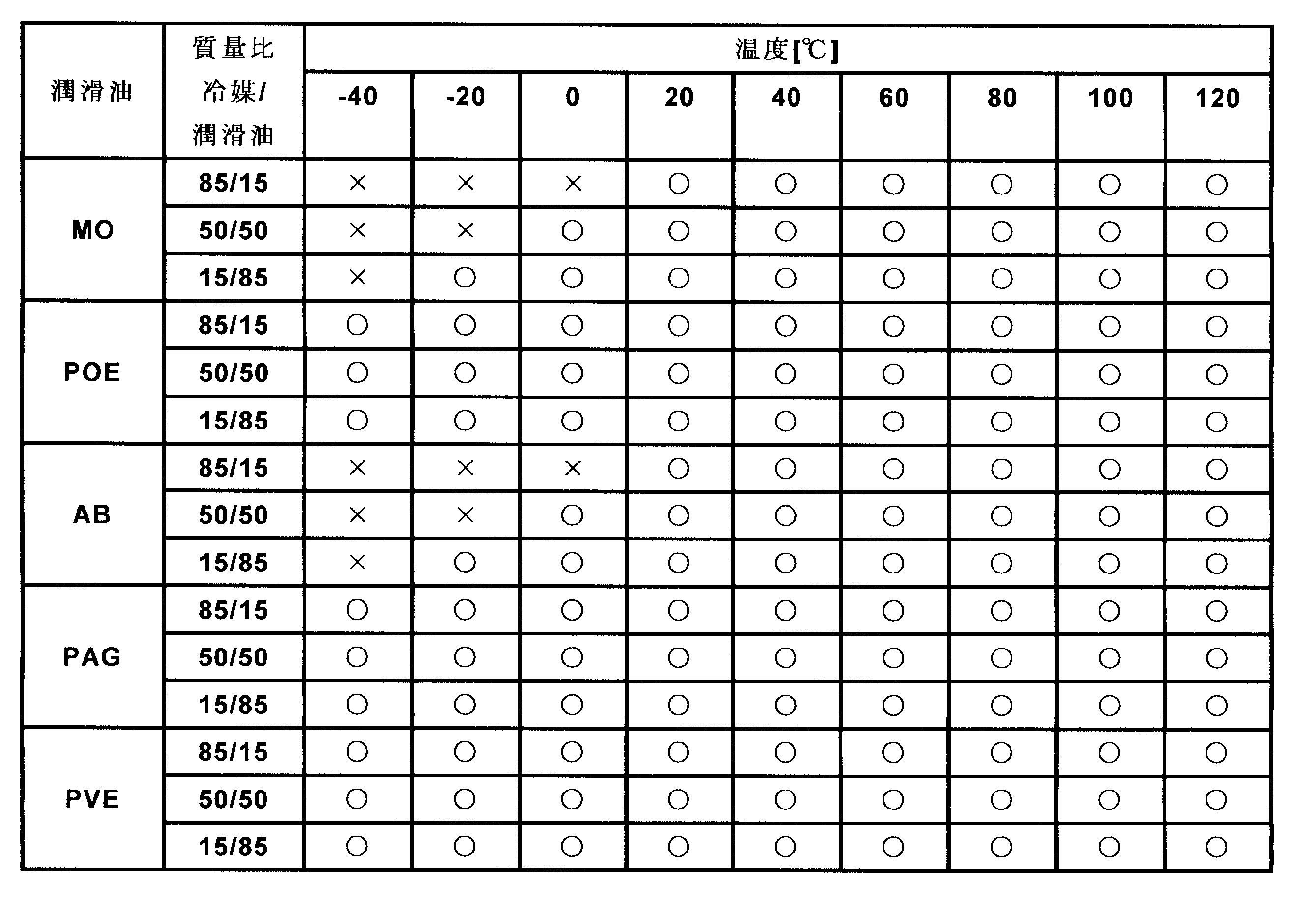
[実施例5]
冷媒をトランス-2-クロロ-1,3,3,3-テトラフルオロプロペン(HCFO-1224xe(E))とした以外は、実施例4と同様の条件で、冷媒と潤滑油との相溶性試験を行った。結果を表5に示す。表5において、均一に相溶したときは○、二層分離または組成物に濁りを生じたときは×で評価した。
冷媒をトランス-2-クロロ-1,3,3,3-テトラフルオロプロペン(HCFO-1224xe(E))とした以外は、実施例4と同様の条件で、冷媒と潤滑油との相溶性試験を行った。結果を表5に示す。表5において、均一に相溶したときは○、二層分離または組成物に濁りを生じたときは×で評価した。
<HCFO-1224xe(E)と潤滑油の相溶性試験>
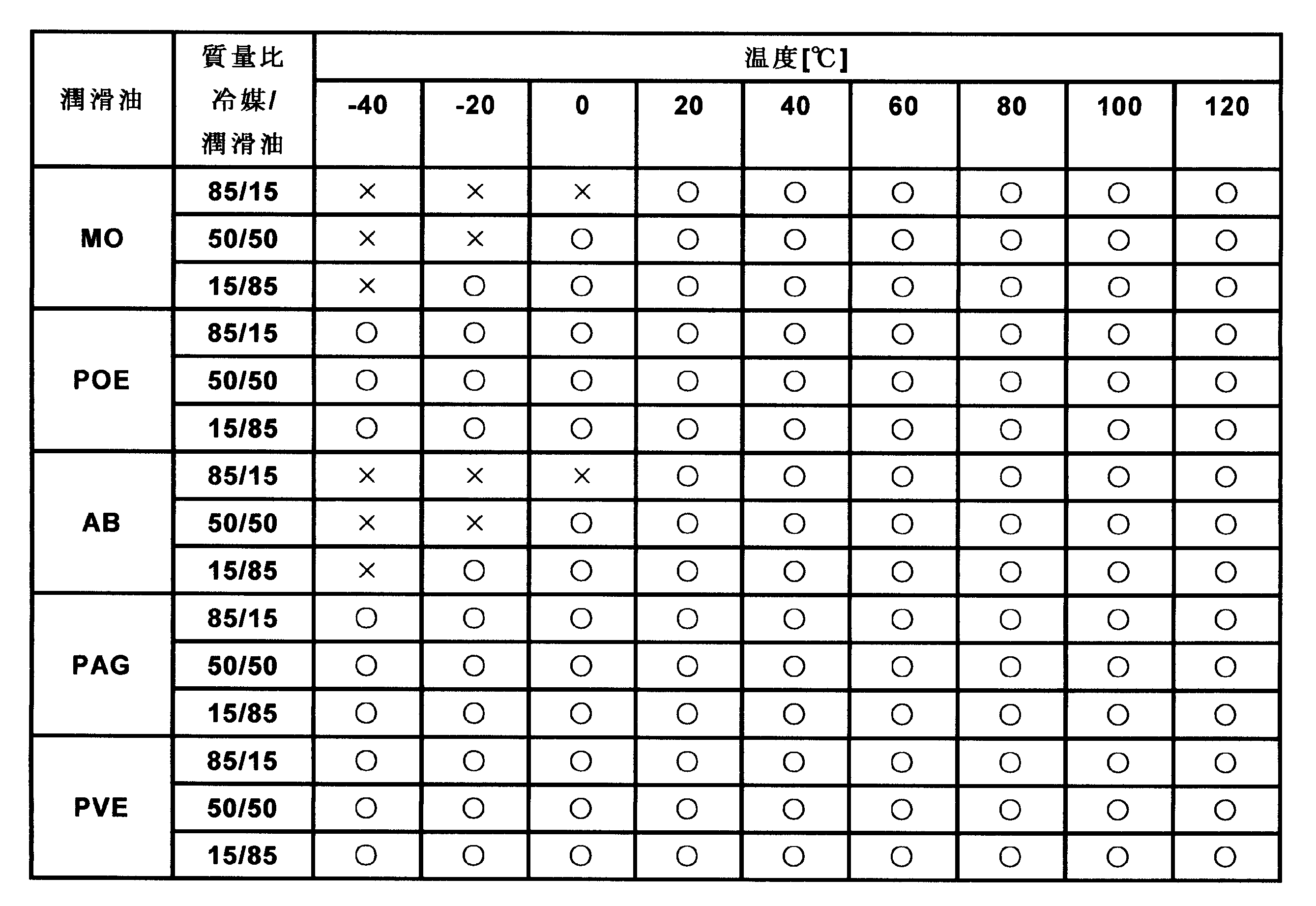
[比較例1]
冷媒をシス-1,3,3,3-テトラフルオロプロペン(HFO-1234ze(Z))としたこと以外は、実施例4及び実施例5と同様にして冷媒と潤滑油との相溶性試験を行った。得られた結果を表6に示す。表6において、均一に相溶したときは○、二層分離または組成物に濁りを生じたときは×で評価した。
冷媒をシス-1,3,3,3-テトラフルオロプロペン(HFO-1234ze(Z))としたこと以外は、実施例4及び実施例5と同様にして冷媒と潤滑油との相溶性試験を行った。得られた結果を表6に示す。表6において、均一に相溶したときは○、二層分離または組成物に濁りを生じたときは×で評価した。
<HFO-1234ze(Z)と潤滑油の相溶性試験>
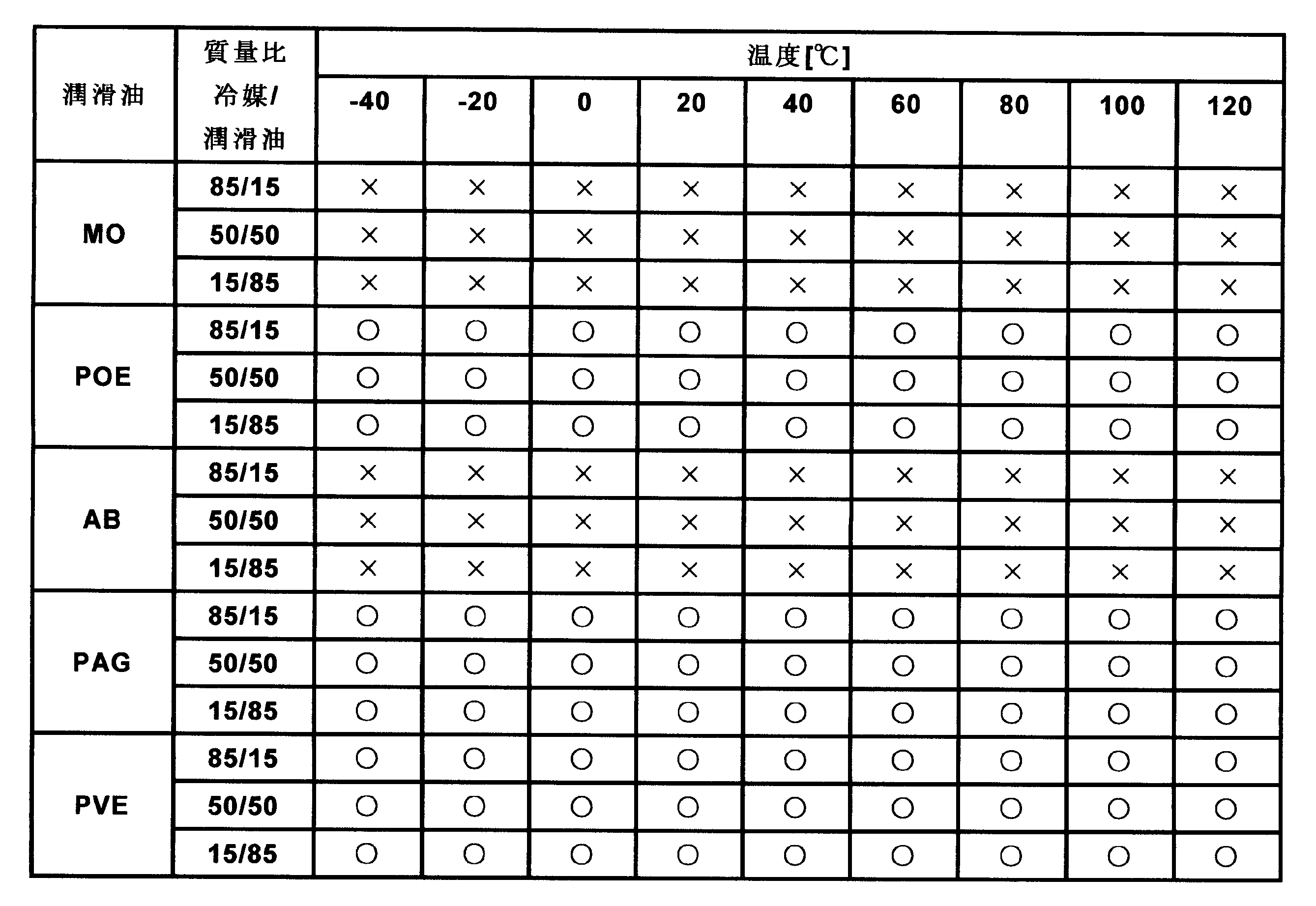
表4および表5に示す通り、シス-2-クロロ-1,3,3,3-テトラフルオロプロペン(HCFO-1224xe(Z))及びトランス-2-クロロ-1,3,3,3-テトラフルオロプロペン(HCFO-1224xe(E))は、含酸素の潤滑油であるPOE、PAGおよびPVEに対して、良好な相溶性を有した。また、シス-2-クロロ-1,3,3,3-テトラフルオロプロペン(HCFO-1224xe(Z))及びトランス-2-クロロ-1,3,3,3-テトラフルオロプロペン(HCFO-1224xe(E))は、酸素を含まない潤滑油であるMOおよびABに対しても、20℃以上の温度条件では相溶性を有することが分かる。表6に示した比較例1の結果を参照すると、シス-1,3,3,3-テトラフルオロプロペン(HFO-1234ze(Z))は、酸素を含まない潤滑油であるMOおよびABに対して全ての温度条件下で完全に二相分離していた。したがって、2-クロロ-1,3,3,3-テトラフルオロプロペン(HCFO-1224xe)を冷凍サイクルシステムまたは高温ヒートポンプサイクルシステムの熱伝達媒体として用いる場合は、含酸素の潤滑油であるPOE、PAGおよびPVEだけでなく、酸素を含まない潤滑油であるMOおよびABも潤滑油として適用できることがわかる。
[実施例6]
日本工業規格JIS K2265-1「引火点の求め方-第1部:タグ密閉法」に準拠して、シス-2-クロロ-1,3,3,3-テトラフルオロプロペン(HCFO-1224xe(Z))及びトランス-2-クロロ-1,3,3,3-テトラフルオロプロペン(HCFO-1224xe(E))の引火点をそれぞれ測定した。引火点測定には、自動引火点測定器atg-8l(田中科学機器製作株式会社)を使用した。
日本工業規格JIS K2265-1「引火点の求め方-第1部:タグ密閉法」に準拠して、シス-2-クロロ-1,3,3,3-テトラフルオロプロペン(HCFO-1224xe(Z))及びトランス-2-クロロ-1,3,3,3-テトラフルオロプロペン(HCFO-1224xe(E))の引火点をそれぞれ測定した。引火点測定には、自動引火点測定器atg-8l(田中科学機器製作株式会社)を使用した。
この結果、シス-2-クロロ-1,3,3,3-テトラフルオロプロペン(HCFO-1224xe(Z))、及びトランス-2-クロロ-1,3,3,3-テトラフルオロプロペン(HCFO-1224xe(E))はともに、大気圧力条件下で引火点がないことが観測された。
[実施例7]
2002年版の米国試験材料協会(ASTM)規格E-681および2010年版の米国暖房冷房空調学会(ASHRAE)規格34-2010に準拠して、シス-2-クロロ-1,3,3,3-テトラフルオロプロペン(HCFO-1224xe(Z))及びトランス-2-クロロ-1,3,3,3-テトラフルオロプロペン(HCFO-1224xe(E))の燃焼範囲を測定した。
2002年版の米国試験材料協会(ASTM)規格E-681および2010年版の米国暖房冷房空調学会(ASHRAE)規格34-2010に準拠して、シス-2-クロロ-1,3,3,3-テトラフルオロプロペン(HCFO-1224xe(Z))及びトランス-2-クロロ-1,3,3,3-テトラフルオロプロペン(HCFO-1224xe(E))の燃焼範囲を測定した。
その結果、シス-2-クロロ-1,3,3,3-テトラフルオロプロペン(HCFO-1224xe(Z))は、23℃、101.3kPa、相対湿度50%の条件において、燃焼範囲がみられず、不燃性であった。また、60℃、101.3kPa、相対湿度50%の条件においても、燃焼範囲がみられず、不燃性であった。
また、トランス-2-クロロ-1,3,3,3-テトラフルオロプロペン(HCFO-1224xe(E))も、前記シス体と同様に、23℃、101.3kPa、相対湿度50%の条件において、燃焼範囲がみられず、不燃性であった。また、60℃、101.3kPa、相対湿度50%の条件においても、燃焼範囲がみられず、不燃性であった。
実施例7の結果から、2-クロロ-1,3,3,3-テトラフルオロプロペン(HCFO-1224xe)はシス体(HCFO-1224xe(Z))及びトランス体(HCFO-1224xe(E))ともに不燃性の化合物であると判定された。米国暖房冷房空調学会(ASHRAE)の冷媒区分によると、区分1(不燃性の冷媒)に該当することがわかる。
[実施例8]
<シス-2-クロロ-1,3,3,3-テトラフルオロプロペンを用いた冷凍サイクルシステム>
シス-2-クロロ-1,3,3,3-テトラフルオロプロペン(HCFO-1224xe(Z))を熱伝達媒体として用いた冷凍サイクルシステム及び高温ヒートポンプサイクルシステムの性能評価において、表7に示す条件で成績係数(COPR、COPH)を算出した。熱伝達媒体の物性値は、米国国立標準技術研究所(NIST)のREFPROP ver.9.0により求めた。
<シス-2-クロロ-1,3,3,3-テトラフルオロプロペンを用いた冷凍サイクルシステム>
シス-2-クロロ-1,3,3,3-テトラフルオロプロペン(HCFO-1224xe(Z))を熱伝達媒体として用いた冷凍サイクルシステム及び高温ヒートポンプサイクルシステムの性能評価において、表7に示す条件で成績係数(COPR、COPH)を算出した。熱伝達媒体の物性値は、米国国立標準技術研究所(NIST)のREFPROP ver.9.0により求めた。
冷凍サイクルシステム計算条件1を以下の表7に示す。
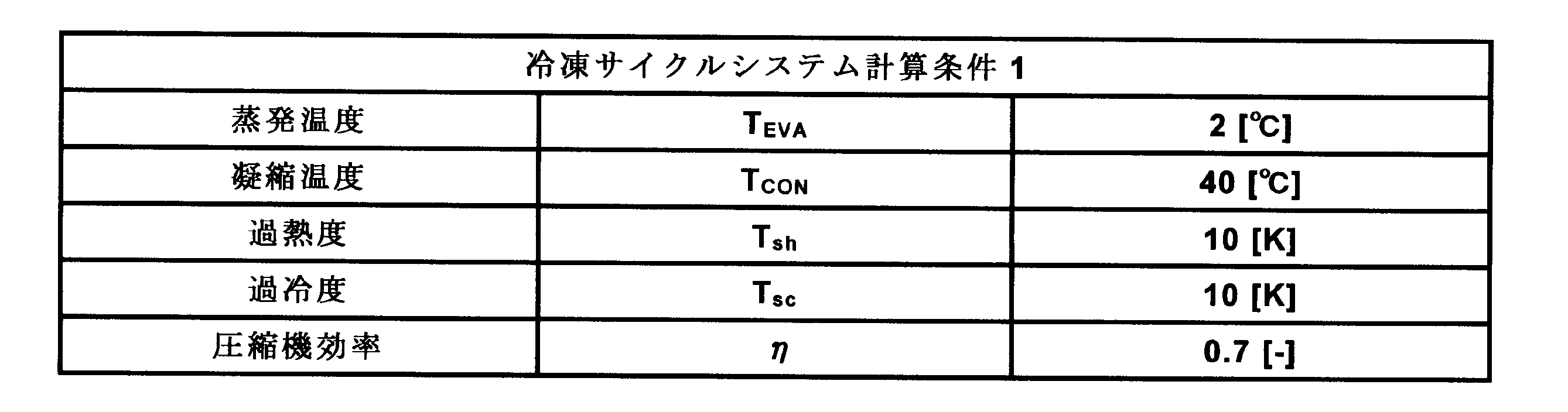
冷凍サイクルシステム計算条件1は、蒸発器において、熱伝達媒体と熱源水との熱交換による7℃冷水の生成を想定している。
なお、冷凍サイクルシステムの成績係数(COPR)を算出するにあたり、次の項目を仮定した。
(A)圧縮機の圧縮過程は等エントロピー圧縮とする。
(B)膨張弁における絞り膨張過程は等エンタルピー膨張とする。
(C)配管および熱交換器における熱損失、圧力損失は無視する。
(D)圧縮機効率ηを0.7とする。
(A)圧縮機の圧縮過程は等エントロピー圧縮とする。
(B)膨張弁における絞り膨張過程は等エンタルピー膨張とする。
(C)配管および熱交換器における熱損失、圧力損失は無視する。
(D)圧縮機効率ηを0.7とする。
以下に、冷凍サイクルシステムの成績係数(COPR)を算出する式について詳細に説明する。蒸発器への入熱量QEVAは、
QEVA=G×(h1-h4)・・・(1)
であり,凝縮器における放熱量QCONは、
QCON=G×(h2-h3)・・・(2)
となる。
QEVA=G×(h1-h4)・・・(1)
であり,凝縮器における放熱量QCONは、
QCON=G×(h2-h3)・・・(2)
となる。
ただし、等エントロピー圧縮後の圧縮機出口における熱伝達媒体のエンタルピーをh2thで表したとき、圧縮機効率を加味したときの圧縮機出口における熱伝達媒体のエンタルピーh2は、
h2=h1+(h2th-h1)/η・・・(3)
となる。
h2=h1+(h2th-h1)/η・・・(3)
となる。
熱伝達媒体の蒸気を圧縮する際に、圧縮機によって加えられた仕事量Wは、
W=G×(h2-h1)・・・(4)
となる。
W=G×(h2-h1)・・・(4)
となる。
冷凍サイクルシステムの成績係数(COPR)は、
COPR=QEVA/W=(h1-h4)/(h2-h1)・・・(5)
となる。
COPR=QEVA/W=(h1-h4)/(h2-h1)・・・(5)
となる。
また、高温ヒートポンプサイクルシステムの成績係数(COPH)は、
COPH=QCON/W=(h2-h3)/(h2-h1)・・・(6)
となる。
COPH=QCON/W=(h2-h3)/(h2-h1)・・・(6)
となる。
次に、熱伝達媒体の体積能力(CAP)を算出する式について詳細に説明する。圧縮機吸い込み口における熱伝達媒体の蒸気密度はρ2であり、蒸発器における吸熱量QEVAであるから、冷凍サイクルシステムの体積能力(CAPR)は、
CAPR=ρ2×QEVA=ρ2×(h1-h4)・・・(7)
となる。
CAPR=ρ2×QEVA=ρ2×(h1-h4)・・・(7)
となる。
また、高温ヒートポンプサイクルシステムの体積能力(CAPH)は、
CAPH=ρ2×QCON=ρ2×(h2-h3)・・・(8)
となる。
CAPH=ρ2×QCON=ρ2×(h2-h3)・・・(8)
となる。
なお、上記(1)~(8)において、各種記号は以下を意味する。
G :熱伝達媒体循環量
W :圧縮仕事
QEVA :入熱量
QCON :放熱量
COPR:成績係数(冷却)
COPH:成績係数(加熱)
CAPR:体積能力(冷却)
CAPH:体積能力(加熱)
h :比エンタルピー
1,2,3,4:サイクルポイント
2th :等エントロピー圧縮後のサイクルポイント
G :熱伝達媒体循環量
W :圧縮仕事
QEVA :入熱量
QCON :放熱量
COPR:成績係数(冷却)
COPH:成績係数(加熱)
CAPR:体積能力(冷却)
CAPH:体積能力(加熱)
h :比エンタルピー
1,2,3,4:サイクルポイント
2th :等エントロピー圧縮後のサイクルポイント
図3は、実施例8(シス-2-クロロ-1,3,3,3-テトラフルオロプロペン(HCFO-1224xe(Z)))におけるPh線図を示す。図において、サイクルポイント1、2、3、4は冷凍サイクルシステム計算条件1を示す。
[実施例9]
<トランス-2-クロロ-1,3,3,3-テトラフルオロプロペンを用いた冷凍サイクルシステム>
トランス-2-クロロ-1,3,3,3-テトラフルオロプロペン(HCFO-1224xe(E))を熱伝達媒体として用いた冷凍サイクルシステムの性能評価において、表7に示す条件で成績係数を算出した。なお、図4は、実施例9(トランス-2-クロロ-1,3,3,3-テトラフルオロプロペン(HCFO-1224xe(E)))におけるPh線図を示す。
<トランス-2-クロロ-1,3,3,3-テトラフルオロプロペンを用いた冷凍サイクルシステム>
トランス-2-クロロ-1,3,3,3-テトラフルオロプロペン(HCFO-1224xe(E))を熱伝達媒体として用いた冷凍サイクルシステムの性能評価において、表7に示す条件で成績係数を算出した。なお、図4は、実施例9(トランス-2-クロロ-1,3,3,3-テトラフルオロプロペン(HCFO-1224xe(E)))におけるPh線図を示す。
[実施例10]
<シス-2-クロロ-1,3,3,3-テトラフルオロプロペンおよびトランス-2-クロロ-1,3,3,3-テトラフルオロプロペンを用いた冷凍サイクルシステム>
シス-2-クロロ-1,3,3,3-テトラフルオロプロペン(HCFO-1224xe(Z))およびトランス-2-クロロ-1,3,3,3-テトラフルオロプロペン(HCFO-1224xe(E))の混合物を熱伝達媒体として用いた冷凍サイクルシステムの性能評価において、表7に示す条件で成績係数を算出した。なお、図5は、実施例10(シス-2-クロロ-1,3,3,3-テトラフルオロプロペン(HCFO-1224xe(Z))およびトランス-2-クロロ-1,3,3,3-テトラフルオロプロペン(HCFO-1224xe(E))の質量比が95:5)におけるPh線図を示す。
<シス-2-クロロ-1,3,3,3-テトラフルオロプロペンおよびトランス-2-クロロ-1,3,3,3-テトラフルオロプロペンを用いた冷凍サイクルシステム>
シス-2-クロロ-1,3,3,3-テトラフルオロプロペン(HCFO-1224xe(Z))およびトランス-2-クロロ-1,3,3,3-テトラフルオロプロペン(HCFO-1224xe(E))の混合物を熱伝達媒体として用いた冷凍サイクルシステムの性能評価において、表7に示す条件で成績係数を算出した。なお、図5は、実施例10(シス-2-クロロ-1,3,3,3-テトラフルオロプロペン(HCFO-1224xe(Z))およびトランス-2-クロロ-1,3,3,3-テトラフルオロプロペン(HCFO-1224xe(E))の質量比が95:5)におけるPh線図を示す。
[比較例2]
<2,2-ジクロロ-1,1,1-トリフルオロエタン>
2,2-ジクロロ-1,1,1-トリフルオロエタン(HCFC-123)は、不燃性であり、許容濃度が10ppmである。なお、HCFC-123の沸点は、大気圧下において27.8℃、大気寿命は1.3年、地球温暖化係数(GWP)は77(IPCC4次評価報告書 2007)、オゾン破壊係数(ODP)は0.02である。
<2,2-ジクロロ-1,1,1-トリフルオロエタン>
2,2-ジクロロ-1,1,1-トリフルオロエタン(HCFC-123)は、不燃性であり、許容濃度が10ppmである。なお、HCFC-123の沸点は、大気圧下において27.8℃、大気寿命は1.3年、地球温暖化係数(GWP)は77(IPCC4次評価報告書 2007)、オゾン破壊係数(ODP)は0.02である。
本発明の熱伝達媒体である2-クロロ-1,3,3,3-テトラフルオロプロペン(HCFO-1224xe)の代わりに、2,2-ジクロロ-1,1,1-トリフルオロエタン(HCFC-123)を熱伝達媒体として用いた冷凍サイクルシステムの性能評価において、表7に示す条件で成績係数を算出した。なお、図6は、比較例2(HCFC-123)におけるPh線図を示す。
上述した実施例8、実施例9および比較例2の冷凍サイクルシステム成績係数(COPR)の算出結果を表8に示す。
表8および表9に示した実施例8及び実施例9の相対COPRおよび相対CAPRは、表8に示した比較例2のCOPRおよびCAPRをそれぞれ1.00とする相対値として算出した。

実施例10の冷凍サイクルシステム成績係数(COPR)の算出結果を表9に示す。表9において、熱伝達媒体の第1成分および第2成分の値は質量百分率で示す。混合物の熱伝達媒体の第1成分がシス-2-クロロ-1,3,3,3-テトラフルオロプロペン(HCFO-1224xe(Z))であり、第2成分がトランス-2-クロロ-1,3,3,3-テトラフルオロプロペン(HCFO-1224xe(E))である。また、実施例10の相対COPRおよび相対CAPRは、表8に示した比較例2のCOPRおよびCAPRをそれぞれ1.00とする相対値として算出した。

表8および表9に示す通り、本発明の熱伝達媒体である2-クロロ-1,3,3,3-テトラフルオロプロペン(HCFO-1224xe)は、従来使用されてきた2,2-ジクロロ-1,1,1-トリフルオロエタン(HCFC-123)と同等の成績係数(COPR)を有していることがわかる。また、本発明の熱伝達媒体である2-クロロ-1,3,3,3-テトラフルオロプロペン(HCFO-1224xe)の体積能力は、HCFC-123の体積能力よりも16~45%大きいことが分かった。これらの結果は、HCFC-123用の冷凍サイクルシステムと同レベルの冷却能力を有する2-クロロ-1,3,3,3-テトラフルオロプロペン(HCFO-1224xe)用の冷凍サイクルシステムを設計する場合、HCFC-123用システムと比して、システム全体のサイズをより小型化できることを意味する。
本発明の熱伝達媒体である2-クロロ-1,3,3,3-テトラフルオロプロペン(HCFO-1224xe)は、HCFC-123の運転圧力、圧力比、圧力差に対して同程度であることが見出され、より環境適合性の高い代替組成物として使用されることがわかる。
[実施例11]
<シス-2-クロロ-1,3,3,3-テトラフルオロプロペンを用いた高温ヒートポンプサイクルシステム(I)>
シス-2-クロロ-1,3,3,3-テトラフルオロプロペン(HCFO-1224xe(Z))を熱伝達媒体として用いた高温ヒートポンプサイクルシステムの性能評価において、表10に示す条件で成績係数を算出した。熱伝達媒体の物性値は、米国国立標準技術研究所(NIST)のREFPROP ver.9.0により求めた。
<シス-2-クロロ-1,3,3,3-テトラフルオロプロペンを用いた高温ヒートポンプサイクルシステム(I)>
シス-2-クロロ-1,3,3,3-テトラフルオロプロペン(HCFO-1224xe(Z))を熱伝達媒体として用いた高温ヒートポンプサイクルシステムの性能評価において、表10に示す条件で成績係数を算出した。熱伝達媒体の物性値は、米国国立標準技術研究所(NIST)のREFPROP ver.9.0により求めた。
高温ヒートポンプサイクルシステム計算条件2を以下の表10に示す。
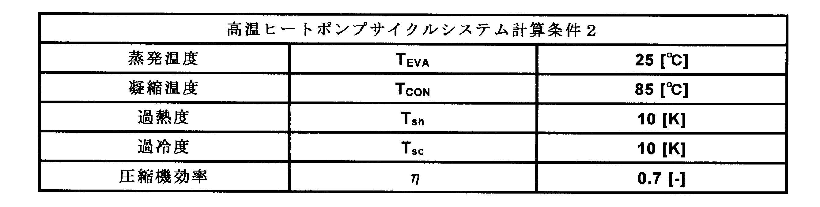
高温ヒートポンプサイクルシステム計算条件2は、凝縮器において、熱伝達媒体と熱源水との熱交換による80℃熱水の生成を想定している。
なお、高温ヒートポンプサイクルシステム成績係数(COPH)を算出するにあたり、次の項目を仮定した。
(A)圧縮機の圧縮過程は等エントロピー圧縮とする。
(B)膨張弁における絞り膨張過程は等エンタルピー膨張とする。
(C)配管および熱交換器における熱損失、圧力損失は無視する。
(D)圧縮機効率ηを0.7とする。
(A)圧縮機の圧縮過程は等エントロピー圧縮とする。
(B)膨張弁における絞り膨張過程は等エンタルピー膨張とする。
(C)配管および熱交換器における熱損失、圧力損失は無視する。
(D)圧縮機効率ηを0.7とする。
図7は、実施例11(シス-2-クロロ-1,3,3,3-テトラフルオロプロペン(HCFO-1224xe(Z)))におけるPh線図を示す。図において、サイクルポイント1、2、3、4は高温ヒートポンプサイクルシステム計算条件2を示す。
[実施例12]
<トランス-2-クロロ-1,3,3,3-テトラフルオロプロペンを用いた高温ヒートポンプサイクルシステム>
トランス-2-クロロ-1,3,3,3-テトラフルオロプロペン(HCFO-1224xe(E))を熱伝達媒体として用いた高温ヒートポンプサイクルシステムの性能評価において、表10に示す条件で成績係数を算出した。なお、図8は、実施例12(トランス-2-クロロ-1,3,3,3-テトラフルオロプロペン(HCFO-1224xe(E)))におけるPh線図を示す。
<トランス-2-クロロ-1,3,3,3-テトラフルオロプロペンを用いた高温ヒートポンプサイクルシステム>
トランス-2-クロロ-1,3,3,3-テトラフルオロプロペン(HCFO-1224xe(E))を熱伝達媒体として用いた高温ヒートポンプサイクルシステムの性能評価において、表10に示す条件で成績係数を算出した。なお、図8は、実施例12(トランス-2-クロロ-1,3,3,3-テトラフルオロプロペン(HCFO-1224xe(E)))におけるPh線図を示す。
[実施例13]
<シス-2-クロロ-1,3,3,3-テトラフルオロプロペンおよびトランス-2-クロロ-1,3,3,3-テトラフルオロプロペンを用いた高温ヒートポンプサイクルシステム>
シス-2-クロロ-1,3,3,3-テトラフルオロプロペン(HCFO-1224xe(Z))およびトランス-2-クロロ-1,3,3,3-テトラフルオロプロペン(HCFO-1224xe(E))の混合熱伝達媒体を用いた高温ヒートポンプサイクルシステムの性能評価において、表10に示す条件で成績係数を算出した。なお、図9は、実施例13(シス-2-クロロ-1,3,3,3-テトラフルオロプロペン(HCFO-1224xe(Z))およびトランス-2-クロロ-1,3,3,3-テトラフルオロプロペン(HCFO-1224xe(E))の質量比が95:5)におけるPh線図を示す。
<シス-2-クロロ-1,3,3,3-テトラフルオロプロペンおよびトランス-2-クロロ-1,3,3,3-テトラフルオロプロペンを用いた高温ヒートポンプサイクルシステム>
シス-2-クロロ-1,3,3,3-テトラフルオロプロペン(HCFO-1224xe(Z))およびトランス-2-クロロ-1,3,3,3-テトラフルオロプロペン(HCFO-1224xe(E))の混合熱伝達媒体を用いた高温ヒートポンプサイクルシステムの性能評価において、表10に示す条件で成績係数を算出した。なお、図9は、実施例13(シス-2-クロロ-1,3,3,3-テトラフルオロプロペン(HCFO-1224xe(Z))およびトランス-2-クロロ-1,3,3,3-テトラフルオロプロペン(HCFO-1224xe(E))の質量比が95:5)におけるPh線図を示す。
[比較例3]
<2,2-ジクロロ-1,1,1-トリフルオロエタンを用いた高温ヒートポンプサイクルシステム(I)>
本発明の熱伝達媒体である2-クロロ-1,3,3,3-テトラフルオロプロペン(HCFO-1224xe)の代わりに、2,2-ジクロロ-1,1,1-トリフルオロエタン(HCFC-123)を熱伝達媒体として用いた高温ヒートポンプサイクルシステムの性能評価において、表10に示す条件で成績係数を算出した。なお、図10は、比較例3(HCFC-123)におけるPh線図を示す。
<2,2-ジクロロ-1,1,1-トリフルオロエタンを用いた高温ヒートポンプサイクルシステム(I)>
本発明の熱伝達媒体である2-クロロ-1,3,3,3-テトラフルオロプロペン(HCFO-1224xe)の代わりに、2,2-ジクロロ-1,1,1-トリフルオロエタン(HCFC-123)を熱伝達媒体として用いた高温ヒートポンプサイクルシステムの性能評価において、表10に示す条件で成績係数を算出した。なお、図10は、比較例3(HCFC-123)におけるPh線図を示す。
実施例11、実施例12および比較例3の高温ヒートポンプサイクルシステム成績係数(COPH)の算出結果を以下の表11に示す。
表11および表12に示した実施例11及び実施例12の相対COPHおよび相対CAPHは、表11に示した比較例3のCOPHおよびCAPHをそれぞれ1.00とする相対値として算出した。
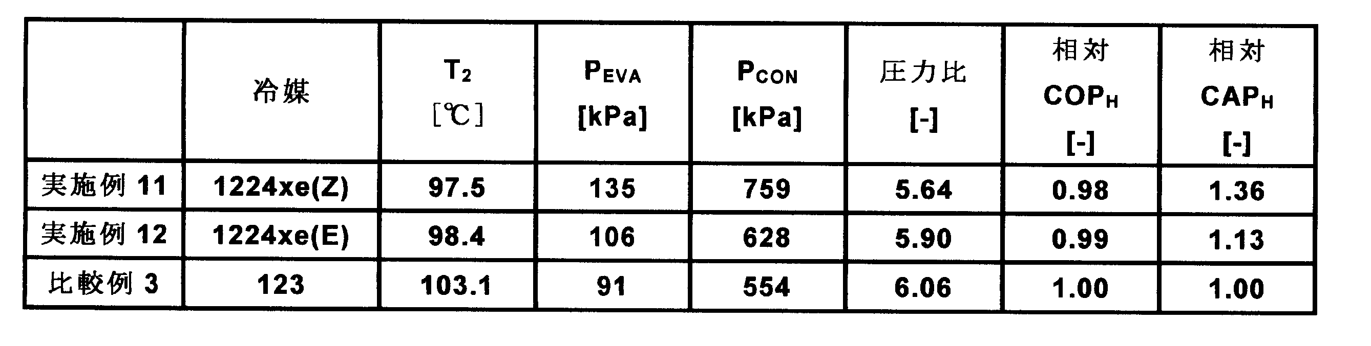
実施例13の高温ヒートポンプサイクルシステム成績係数(COPH)の算出結果を表12に示す。表12において、熱伝達媒体の第1成分および第2成分の値は質量百分率で示す。混合物の熱伝達媒体において、第1成分がシス-2-クロロ-1,3,3,3-テトラフルオロプロペン(HCFO-1224xe(Z))であり、第2成分がトランス-2-クロロ-1,3,3,3-テトラフルオロプロペン(HCFO-1224xe(E))である。また、実施例13の相対COPHおよび相対CAPHは、表11に示した比較例3のCOPHおよびCAPHをそれぞれ1.00とする相対値として算出した。

表11および表12に示す通り、本発明の熱伝達媒体である2-クロロ-1,3,3,3-テトラフルオロプロペン(HCFO-1224xe)は、従来使用されてきた2,2-ジクロロ-1,1,1-トリフルオロエタン(HCFC-123)と同等の成績係数(COPH)を有していることがわかる。また、本発明の熱伝達媒体である2-クロロ-1,3,3,3-テトラフルオロプロペン(HCFO-1224xe)の体積能力(CAPH)は、HCFC-123の体積能力よりも13~36%大きいことが分かった。これらの結果は、HCFC-123用の高温ヒートポンプサイクルシステムと同レベルの加熱能力を有する2-クロロ-1,3,3,3-テトラフルオロプロペン(HCFO-1224xe)用の高温ヒートポンプサイクルシステムを設計する場合、HCFC-123用システムと比して、システム全体のサイズをより小型化できることを意味する。
[実施例14]
<シス-2-クロロ-1,3,3,3-テトラフルオロプロペンを用いた高温ヒートポンプサイクルシステム(II)>
シス-2-クロロ-1,3,3,3-テトラフルオロプロペン(HCFO-1224xe(Z))を熱伝達媒体として用いた高温ヒートポンプサイクルの性能評価において、表13に示す条件で成績係数を算出した。
<シス-2-クロロ-1,3,3,3-テトラフルオロプロペンを用いた高温ヒートポンプサイクルシステム(II)>
シス-2-クロロ-1,3,3,3-テトラフルオロプロペン(HCFO-1224xe(Z))を熱伝達媒体として用いた高温ヒートポンプサイクルの性能評価において、表13に示す条件で成績係数を算出した。
高温ヒートポンプサイクルシステム計算条件3を以下の表13に示す。

高温ヒートポンプサイクルシステム計算条件3は、凝縮器において、熱伝達媒体と熱源水との熱交換による120℃加圧熱水の生成を想定している。
図11は、実施例14(シス-2-クロロ-1,3,3,3-テトラフルオロプロペン(HCFO-1224xe(Z)))におけるPh線図を示す。図において、サイクルポイント1、2、3、4は高温ヒートポンプサイクルシステム計算条件3を示す。
[実施例15]
<トランス-2-クロロ-1,3,3,3-テトラフルオロプロペンを用いた高温ヒートポンプサイクルシステム(II)>
トランス-2-クロロ-1,3,3,3-テトラフルオロプロペン(HCFO-1224xe(E))を熱伝達媒体として用いた高温ヒートポンプサイクルシステムの性能評価において、表13に示す条件で成績係数を算出した。なお、図12は、実施例15(トランス-2-クロロ-1,3,3,3-テトラフルオロプロペン(HCFO-1224xe(E)))におけるPh線図を示す。
<トランス-2-クロロ-1,3,3,3-テトラフルオロプロペンを用いた高温ヒートポンプサイクルシステム(II)>
トランス-2-クロロ-1,3,3,3-テトラフルオロプロペン(HCFO-1224xe(E))を熱伝達媒体として用いた高温ヒートポンプサイクルシステムの性能評価において、表13に示す条件で成績係数を算出した。なお、図12は、実施例15(トランス-2-クロロ-1,3,3,3-テトラフルオロプロペン(HCFO-1224xe(E)))におけるPh線図を示す。
[実施例16]
<シス-2-クロロ-1,3,3,3-テトラフルオロプロペンおよびトランス-2-クロロ-1,3,3,3-テトラフルオロプロペンを用いた高温ヒートポンプサイクルシステム(II)>
シス-2-クロロ-1,3,3,3-テトラフルオロプロペン(HCFO-1224xe(Z))およびトランス-2-クロロ-1,3,3,3-テトラフルオロプロペン(HCFO-1224xe(E))の混合熱伝達媒体を用いた高温ヒートポンプサイクルシステムの性能評価において、表13に示す条件で成績係数を算出した。なお、図13は、実施例16(シス-2-クロロ-1,3,3,3-テトラフルオロプロペン(HCFO-1224xe(Z))およびトランス-2-クロロ-1,3,3,3-テトラフルオロプロペン(HCFO-1224xe(E))の質量比が95:5)におけるPh線図を示す。
<シス-2-クロロ-1,3,3,3-テトラフルオロプロペンおよびトランス-2-クロロ-1,3,3,3-テトラフルオロプロペンを用いた高温ヒートポンプサイクルシステム(II)>
シス-2-クロロ-1,3,3,3-テトラフルオロプロペン(HCFO-1224xe(Z))およびトランス-2-クロロ-1,3,3,3-テトラフルオロプロペン(HCFO-1224xe(E))の混合熱伝達媒体を用いた高温ヒートポンプサイクルシステムの性能評価において、表13に示す条件で成績係数を算出した。なお、図13は、実施例16(シス-2-クロロ-1,3,3,3-テトラフルオロプロペン(HCFO-1224xe(Z))およびトランス-2-クロロ-1,3,3,3-テトラフルオロプロペン(HCFO-1224xe(E))の質量比が95:5)におけるPh線図を示す。
[比較例4]
<2,2-ジクロロ-1,1,1-トリフルオロエタンを用いた高温ヒートポンプサイクルシステム(II)>
本発明の熱伝達媒体である2-クロロ-1,3,3,3-テトラフルオロプロペン(HCFO-1224xe)の代わりに、2,2-ジクロロ-1,1,1-トリフルオロエタン(HCFC-123)を熱伝達媒体として用いた高温ヒートポンプサイクルシステムの性能評価において、表13に示す条件で成績係数を算出した。なお、図14は、比較例3(HCFC-123)におけるPh線図を示す。
<2,2-ジクロロ-1,1,1-トリフルオロエタンを用いた高温ヒートポンプサイクルシステム(II)>
本発明の熱伝達媒体である2-クロロ-1,3,3,3-テトラフルオロプロペン(HCFO-1224xe)の代わりに、2,2-ジクロロ-1,1,1-トリフルオロエタン(HCFC-123)を熱伝達媒体として用いた高温ヒートポンプサイクルシステムの性能評価において、表13に示す条件で成績係数を算出した。なお、図14は、比較例3(HCFC-123)におけるPh線図を示す。
実施例14、実施例15および比較例4の高温ヒートポンプサイクルシステム成績係数(COPH)の算出結果を表14に示す。
表14および表15に示した実施例14及び実施例15の相対COPHおよび相対CAPHは、表14に示した比較例4のCOPHおよびCAPHをそれぞれ1.00とする相対値として算出した。

実施例16の高温ヒートポンプサイクルシステム成績係数(COPH)の算出結果を表15に示す。表15において、混合物である熱伝達媒体の第1成分および第2成分の値は質量百分率で示す。混合熱伝達媒体の第1成分がシス-2-クロロ-1,3,3,3-テトラフルオロプロペン(HCFO-1224xe(Z))であり、第2成分がトランス-2-クロロ-1,3,3,3-テトラフルオロプロペン(HCFO-1224xe(E))である。実施例16の相対COPHおよび相対CAPHは、表14に示した比較例4のCOPHおよびCAPHをそれぞれ1.00とする相対値として算出した。
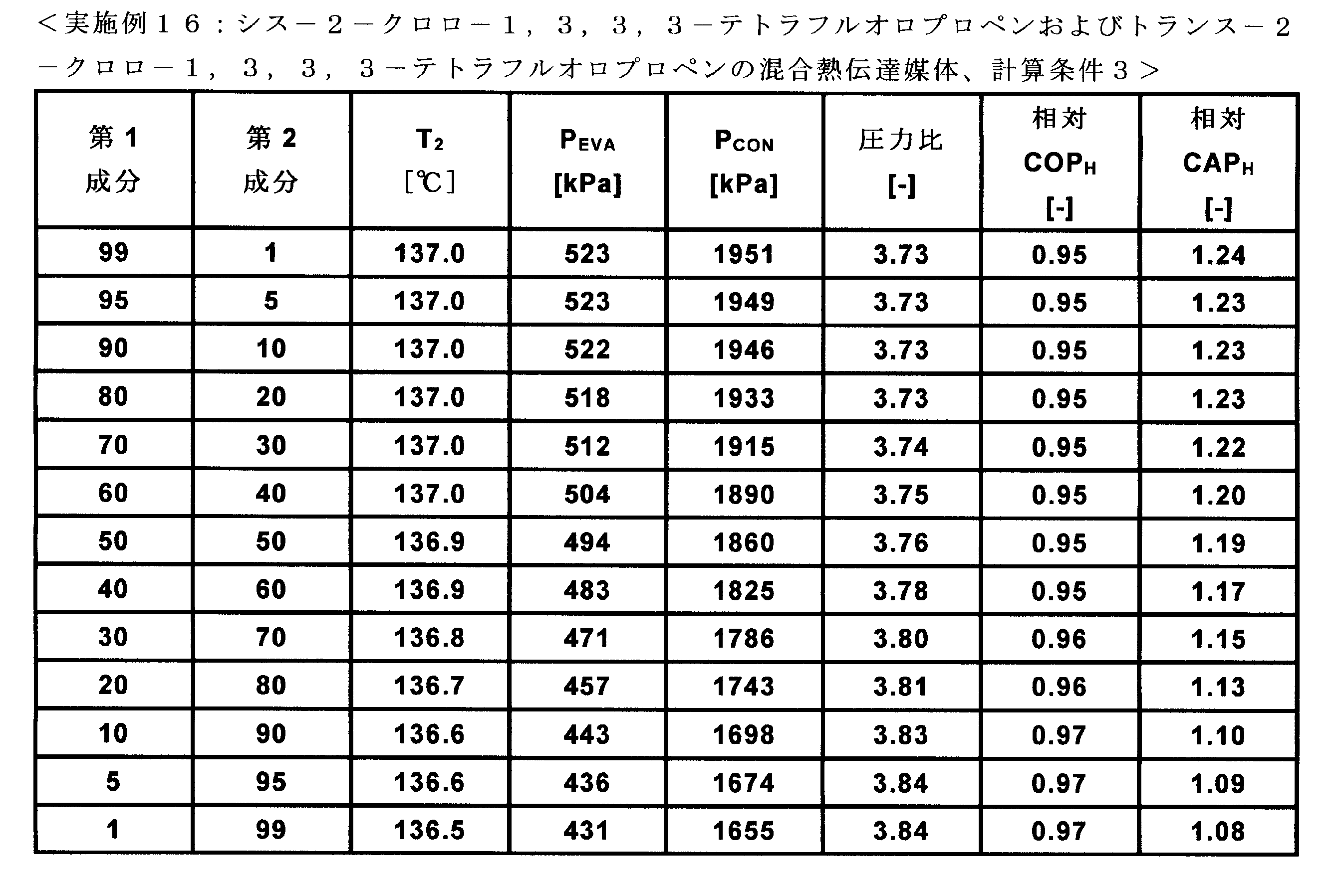
表14および表15に示す通り、本発明の熱伝達媒体である2-クロロ-1,3,3,3-テトラフルオロプロペン(HCFO-1224xe)は、従来使用されてきた2,2-ジクロロ-1,1,1-トリフルオロエタン(HCFC-123)と同等の成績係数(COPH)を有していることがわかる。また、本発明の熱伝達媒体の体積能力(CAPH)は、HCFC-123の体積能力よりも8~24%大きいことが分かった。これらの結果は、HCFC-123用の高温ヒートポンプサイクルシステムと同レベルの加熱能力を有する2-クロロ-1,3,3,3-テトラフルオロプロペン(HCFO-1224xe)用の高温ヒートポンプサイクルシステムを設計する場合、HCFC-123用システムと比して、システム全体のサイズをより小型化できることを意味する。
本発明の熱伝達媒体である2-クロロ-1,3,3,3-テトラフルオロプロペン(HCFO-1224xe)は、HCFC-123の運転圧力、圧力比、圧力差に対して同程度であることが見出され、より環境適合性の高い代替物として使用されることがわかる。
[実施例17]
<シス-2-クロロ-1,3,3,3-テトラフルオロプロペンを用いた有機ランキンサイクルシステム(I)>
シス-2-クロロ-1,3,3,3-テトラフルオロプロペン(HCFO-1224xe(Z))を熱伝達媒体(作動媒体)として用いた有機ランキンサイクルシステムの性能評価において、表16に示す条件で発電サイクル効率および膨張機サイズパラメータを算出した。
<シス-2-クロロ-1,3,3,3-テトラフルオロプロペンを用いた有機ランキンサイクルシステム(I)>
シス-2-クロロ-1,3,3,3-テトラフルオロプロペン(HCFO-1224xe(Z))を熱伝達媒体(作動媒体)として用いた有機ランキンサイクルシステムの性能評価において、表16に示す条件で発電サイクル効率および膨張機サイズパラメータを算出した。
有機ランキンサイクルシステム計算条件4を以下の表16に示す。
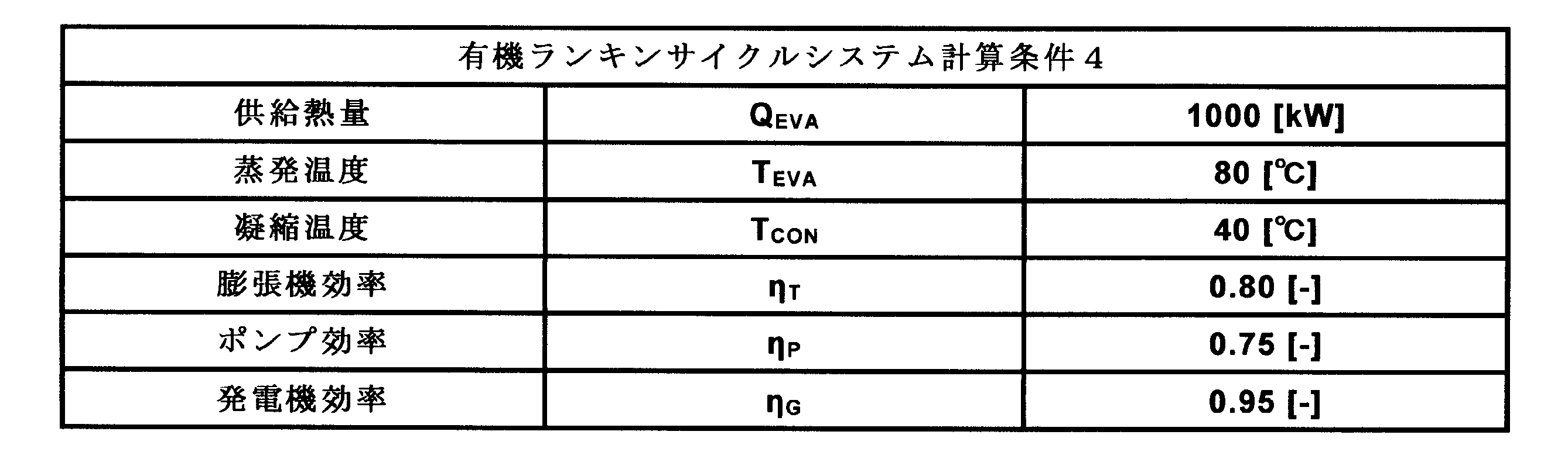
有機ランキンサイクルシステム計算条件4は、蒸発器へ供給する熱源水の温度を90℃、凝縮器へ供給する冷却水の温度を30℃と想定している。
有機ランキンサイクルシステムの発電サイクル効率(ηcycle)および膨張機サイズパラメータ(SP)を算出するにあたり、次の項目を仮定した。
(A)ランキンサイクルの理想的な膨張過程は等エントロピー膨張とし、実機損失を考慮し、膨張機断熱効率ηTを導入する。
(B)膨張機による発電機損失を発電機効率ηGで考慮する。
(C)循環ポンプ動力は発電電気で駆動し、モータ効率を含めポンプ効率ηPを導入する。ポンプはキャンド型で、損失分は熱としてサイクルに含める。
(D)軸受潤滑油の循環ポンプ動力は微小であるため無視する。
(E)配管の熱損失、圧力損失は無視する。
(F)蒸発器出口の作動媒体は飽和蒸気とする。
(G)凝縮器出口の作動媒体は飽和液とする。
(A)ランキンサイクルの理想的な膨張過程は等エントロピー膨張とし、実機損失を考慮し、膨張機断熱効率ηTを導入する。
(B)膨張機による発電機損失を発電機効率ηGで考慮する。
(C)循環ポンプ動力は発電電気で駆動し、モータ効率を含めポンプ効率ηPを導入する。ポンプはキャンド型で、損失分は熱としてサイクルに含める。
(D)軸受潤滑油の循環ポンプ動力は微小であるため無視する。
(E)配管の熱損失、圧力損失は無視する。
(F)蒸発器出口の作動媒体は飽和蒸気とする。
(G)凝縮器出口の作動媒体は飽和液とする。
以下に、有機ランキンサイクルシステムの発電サイクル効率(ηcycle)を算出する基礎式について詳細に説明する。なお、基礎式は、エバラ時報No.211(2006-4)、p.11掲載の「廃熱発電装置の開発(作動媒体及び膨張タービンの検討)」の計算式を用いた。
作動媒体循環量Gによる膨張機の理論発生動力LTthは、
LTth=G×(h1-h2th)・・・(9)
となる。
LTth=G×(h1-h2th)・・・(9)
となる。
膨張機効率ηTを考慮した発生動力LTは、
LT=LTth×ηT=G×(h1-h2)・・・(10)
となる。
LT=LTth×ηT=G×(h1-h2)・・・(10)
となる。
発電機効率ηGを考慮した発電量EGは、
EG=LT×ηG・・・(11)
となる。
EG=LT×ηG・・・(11)
となる。
循環ポンプは、凝縮器出口の作動媒体液を凝縮器圧力PCから圧力の高い蒸発器圧力PEに送り込むもので,その理論的な必要動力LPthは、
LPth=(PE-PC)×G/ρ3・・・(12)
となる。
LPth=(PE-PC)×G/ρ3・・・(12)
となる。
ポンプ効率ηPを考慮した必要電力EPは、
EP=LPth/ηP=G×(h4-h3)・・・(13)
となる。
EP=LPth/ηP=G×(h4-h3)・・・(13)
となる。
有効発電量Ecycleは、
Ecycle=EG-EP・・・(14)
となる。
Ecycle=EG-EP・・・(14)
となる。
蒸発器への供給熱量QEは、
QE=G×(h1-h4)
=G×(h1-h3)-(PE-PC)×G/(ρ3×ηP)・・・(15)
となる。
QE=G×(h1-h4)
=G×(h1-h3)-(PE-PC)×G/(ρ3×ηP)・・・(15)
となる。
発電サイクルとしての効率は、
ηcycle=(EG-EP)×100/QE・・・(16)
となる。
ηcycle=(EG-EP)×100/QE・・・(16)
となる。
次に、膨張機サイズパラメータ(SP)について詳細に説明する。なお、基礎式は非特許文献(Energy2012,Vol.38,P136-143)に記載の計算式を用いた。
作動媒体循環量がGのとき、等エントロピー膨張における膨張機出口の作動媒体体積流量V2thは、
V2th=G/ρ2th・・・(17)
となる。
V2th=G/ρ2th・・・(17)
となる。
膨張機の理論断熱熱落差△Hthは、
△Hth=h1-h2th・・・(18)
となる。
△Hth=h1-h2th・・・(18)
となる。
膨張機サイズパラメータ(SP)は、
SP=(V2th)0.5/(△Hth)0.25・・・(19)
となる。
SP=(V2th)0.5/(△Hth)0.25・・・(19)
となる。
なお、上記(9)~(19)において、各種記号は以下を意味する。
G: 作動媒体循環量
LTth: 膨張機の理論発生動力
LT: 膨張機の発生動力
EG: 発電量
EP: 循環ポンプ必要電力
PC: 凝縮器圧力
PE: 蒸発器圧力
LPth: 循環ポンプの稼動に必要な理論動力
Ecycle: 有効発電量
QE: 入熱量
ηcycle: 発電サイクル効率
V2th: 膨張機出口の理論体積流量
△Hth: 膨張機の理論断熱熱落差
SP: 膨張機サイズパラメータ
ρ: 作動媒体の密度
h: 比エンタルピー
1,2,3,4: サイクルポイント
G: 作動媒体循環量
LTth: 膨張機の理論発生動力
LT: 膨張機の発生動力
EG: 発電量
EP: 循環ポンプ必要電力
PC: 凝縮器圧力
PE: 蒸発器圧力
LPth: 循環ポンプの稼動に必要な理論動力
Ecycle: 有効発電量
QE: 入熱量
ηcycle: 発電サイクル効率
V2th: 膨張機出口の理論体積流量
△Hth: 膨張機の理論断熱熱落差
SP: 膨張機サイズパラメータ
ρ: 作動媒体の密度
h: 比エンタルピー
1,2,3,4: サイクルポイント
図15は、実施例17(シス-2-クロロ-1,3,3,3-テトラフルオロプロペン(HCFO-1224xe(Z)))におけるTs線図を示す。図において、サイクルポイント1、2、3、4は有機ランキンサイクルシステム計算条件4を示す。
[実施例18]
<トランス-2-クロロ-1,3,3,3-テトラフルオロプロペンを用いた有機ランキンサイクルシステム(I)>
トランス-2-クロロ-1,3,3,3-テトラフルオロプロペン(HCFO-1224xe(E))を熱伝達媒体(作動媒体)として用いた有機ランキンサイクルシステムの性能評価において、表16に示す計算条件で発電サイクル効率および膨張機サイズパラメータを算出した。なお、図16は、実施例18におけるTs線図を示す。
<トランス-2-クロロ-1,3,3,3-テトラフルオロプロペンを用いた有機ランキンサイクルシステム(I)>
トランス-2-クロロ-1,3,3,3-テトラフルオロプロペン(HCFO-1224xe(E))を熱伝達媒体(作動媒体)として用いた有機ランキンサイクルシステムの性能評価において、表16に示す計算条件で発電サイクル効率および膨張機サイズパラメータを算出した。なお、図16は、実施例18におけるTs線図を示す。
[実施例19]
<シス-2-クロロ-1,3,3,3-テトラフルオロプロペンおよびトランス-2-クロロ-1,3,3,3-テトラフルオロプロペンを用いた有機ランキンサイクルシステム(I)>
シス-2-クロロ-1,3,3,3-テトラフルオロプロペン(HCFO-1224xe(Z))およびトランス-2-クロロ-1,3,3,3-テトラフルオロプロペン(HCFO-1224xe(E))の混合熱伝達媒体(混合作動媒体)を用いた有機ランキンサイクルシステムの性能評価において、表16に示す計算条件で発電サイクル効率および膨張機サイズパラメータを算出した。なお、図17は、実施例19(シス-2-クロロ-1,3,3,3-テトラフルオロプロペン(HCFO-1224xe(Z)):トランス-2-クロロ-1,3,3,3-テトラフルオロプロペン(HCFO-1224xe(E))の質量比が95:5)におけるTs線図を示す。
<シス-2-クロロ-1,3,3,3-テトラフルオロプロペンおよびトランス-2-クロロ-1,3,3,3-テトラフルオロプロペンを用いた有機ランキンサイクルシステム(I)>
シス-2-クロロ-1,3,3,3-テトラフルオロプロペン(HCFO-1224xe(Z))およびトランス-2-クロロ-1,3,3,3-テトラフルオロプロペン(HCFO-1224xe(E))の混合熱伝達媒体(混合作動媒体)を用いた有機ランキンサイクルシステムの性能評価において、表16に示す計算条件で発電サイクル効率および膨張機サイズパラメータを算出した。なお、図17は、実施例19(シス-2-クロロ-1,3,3,3-テトラフルオロプロペン(HCFO-1224xe(Z)):トランス-2-クロロ-1,3,3,3-テトラフルオロプロペン(HCFO-1224xe(E))の質量比が95:5)におけるTs線図を示す。
[比較例5]
<2,2-ジクロロ-1,1,1-トリフルオロエタンを用いた有機ランキンサイクルシステム(I)>
本発明の熱伝達媒体(作動媒体)である2-クロロ-1,3,3,3-テトラフルオロプロペン(HCFO-1224xe)の代わりに、2,2-ジクロロ-1,1,1-トリフルオロエタン(HCFC-123)を作動媒体として用いた有機ランキンサイクルシステムの性能評価において、表16に示す計算条件で発電サイクル効率および膨張機サイズパラメータを算出した。なお、図18において、比較例5におけるTs線図を示す。
<2,2-ジクロロ-1,1,1-トリフルオロエタンを用いた有機ランキンサイクルシステム(I)>
本発明の熱伝達媒体(作動媒体)である2-クロロ-1,3,3,3-テトラフルオロプロペン(HCFO-1224xe)の代わりに、2,2-ジクロロ-1,1,1-トリフルオロエタン(HCFC-123)を作動媒体として用いた有機ランキンサイクルシステムの性能評価において、表16に示す計算条件で発電サイクル効率および膨張機サイズパラメータを算出した。なお、図18において、比較例5におけるTs線図を示す。
[実施例20]
<シス-2-クロロ-1,3,3,3-テトラフルオロプロペンを用いた有機ランキンサイクルシステム(II)>
シス-2-クロロ-1,3,3,3-テトラフルオロプロペン(HCFO-1224xe(Z))を熱伝達媒体(作動媒体)として用いた有機ランキンサイクルシステムの性能評価において、表17に示す条件で発電サイクル効率および膨張機サイズパラメータを算出した。なお、図19は、実施例20におけるTs線図を示す。
<シス-2-クロロ-1,3,3,3-テトラフルオロプロペンを用いた有機ランキンサイクルシステム(II)>
シス-2-クロロ-1,3,3,3-テトラフルオロプロペン(HCFO-1224xe(Z))を熱伝達媒体(作動媒体)として用いた有機ランキンサイクルシステムの性能評価において、表17に示す条件で発電サイクル効率および膨張機サイズパラメータを算出した。なお、図19は、実施例20におけるTs線図を示す。
以下に、有機ランキンサイクルシステム計算条件5を表17に示す。
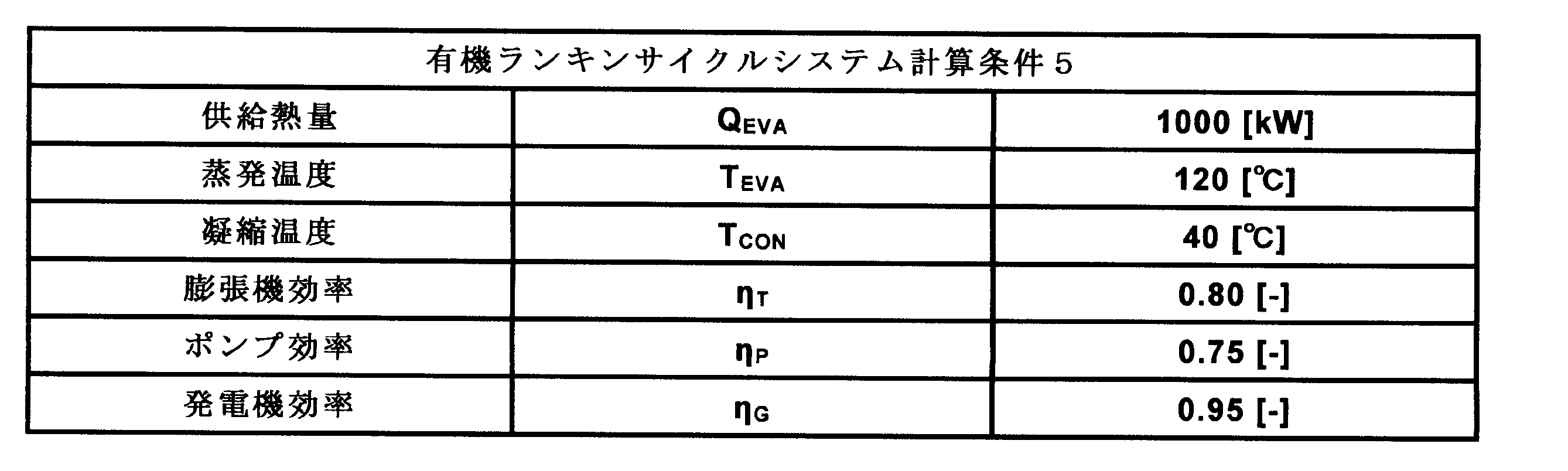
[実施例21]
<トランス-2-クロロ-1,3,3,3-テトラフルオロプロペンを用いた有機ランキンサイクルシステム(II)>
トランス-2-クロロ-1,3,3,3-テトラフルオロプロペン(HCFO-1224xe(E))を熱伝達媒体(作動媒体)として用いた有機ランキンサイクルシステムの性能評価において、表17に示す計算条件で発電サイクル効率および膨張機サイズパラメータを算出した。なお、図20は、実施例21におけるTs線図を示す。
<トランス-2-クロロ-1,3,3,3-テトラフルオロプロペンを用いた有機ランキンサイクルシステム(II)>
トランス-2-クロロ-1,3,3,3-テトラフルオロプロペン(HCFO-1224xe(E))を熱伝達媒体(作動媒体)として用いた有機ランキンサイクルシステムの性能評価において、表17に示す計算条件で発電サイクル効率および膨張機サイズパラメータを算出した。なお、図20は、実施例21におけるTs線図を示す。
[実施例22]
<シス-2-クロロ-1,3,3,3-テトラフルオロプロペンおよびトランス-2-クロロ-1,3,3,3-テトラフルオロプロペンを用いた有機ランキンサイクルシステム(II)>
シス-2-クロロ-1,3,3,3-テトラフルオロプロペン(HCFO-1224xe(Z))およびトランス-2-クロロ-1,3,3,3-テトラフルオロプロペン(HCFO-1224xe(E))の混合熱伝達媒体(混合作動媒体)を用いた有機ランキンサイクルシステムの性能評価において、表17に示す計算条件で発電サイクル効率および膨張機サイズパラメータを算出した。なお、図21において、実施例22(シス-2-クロロ-1,3,3,3-テトラフルオロプロペン(HCFO-1224xe(Z)):トランス-2-クロロ-1,3,3,3-テトラフルオロプロペン(HCFO-1224xe(E))の質量比が95:5)におけるTs線図を示す。
<シス-2-クロロ-1,3,3,3-テトラフルオロプロペンおよびトランス-2-クロロ-1,3,3,3-テトラフルオロプロペンを用いた有機ランキンサイクルシステム(II)>
シス-2-クロロ-1,3,3,3-テトラフルオロプロペン(HCFO-1224xe(Z))およびトランス-2-クロロ-1,3,3,3-テトラフルオロプロペン(HCFO-1224xe(E))の混合熱伝達媒体(混合作動媒体)を用いた有機ランキンサイクルシステムの性能評価において、表17に示す計算条件で発電サイクル効率および膨張機サイズパラメータを算出した。なお、図21において、実施例22(シス-2-クロロ-1,3,3,3-テトラフルオロプロペン(HCFO-1224xe(Z)):トランス-2-クロロ-1,3,3,3-テトラフルオロプロペン(HCFO-1224xe(E))の質量比が95:5)におけるTs線図を示す。
[比較例6]
<2,2-ジクロロ-1,1,1-トリフルオロエタンを用いた有機ランキンサイクルシステム(II)>
本発明の熱伝達媒体(作動媒体)である2-クロロ-1,3,3,3-テトラフルオロプロペン(HCFO-1224xe)の代わりに、2,2-ジクロロ-1,1,1-トリフルオロエタン(HCFC-123)を作動媒体として用いた有機ランキンサイクルシステムの性能評価において、表17に示す計算条件で発電サイクル効率および膨張機サイズパラメータを算出した。なお、図22は、比較例6におけるTs線図を示す。
<2,2-ジクロロ-1,1,1-トリフルオロエタンを用いた有機ランキンサイクルシステム(II)>
本発明の熱伝達媒体(作動媒体)である2-クロロ-1,3,3,3-テトラフルオロプロペン(HCFO-1224xe)の代わりに、2,2-ジクロロ-1,1,1-トリフルオロエタン(HCFC-123)を作動媒体として用いた有機ランキンサイクルシステムの性能評価において、表17に示す計算条件で発電サイクル効率および膨張機サイズパラメータを算出した。なお、図22は、比較例6におけるTs線図を示す。
以上に説明した実施例17、18および比較例5の有機ランキンサイクルシステム性能(ηcycleおよびSP)の算出結果を表18に示す。
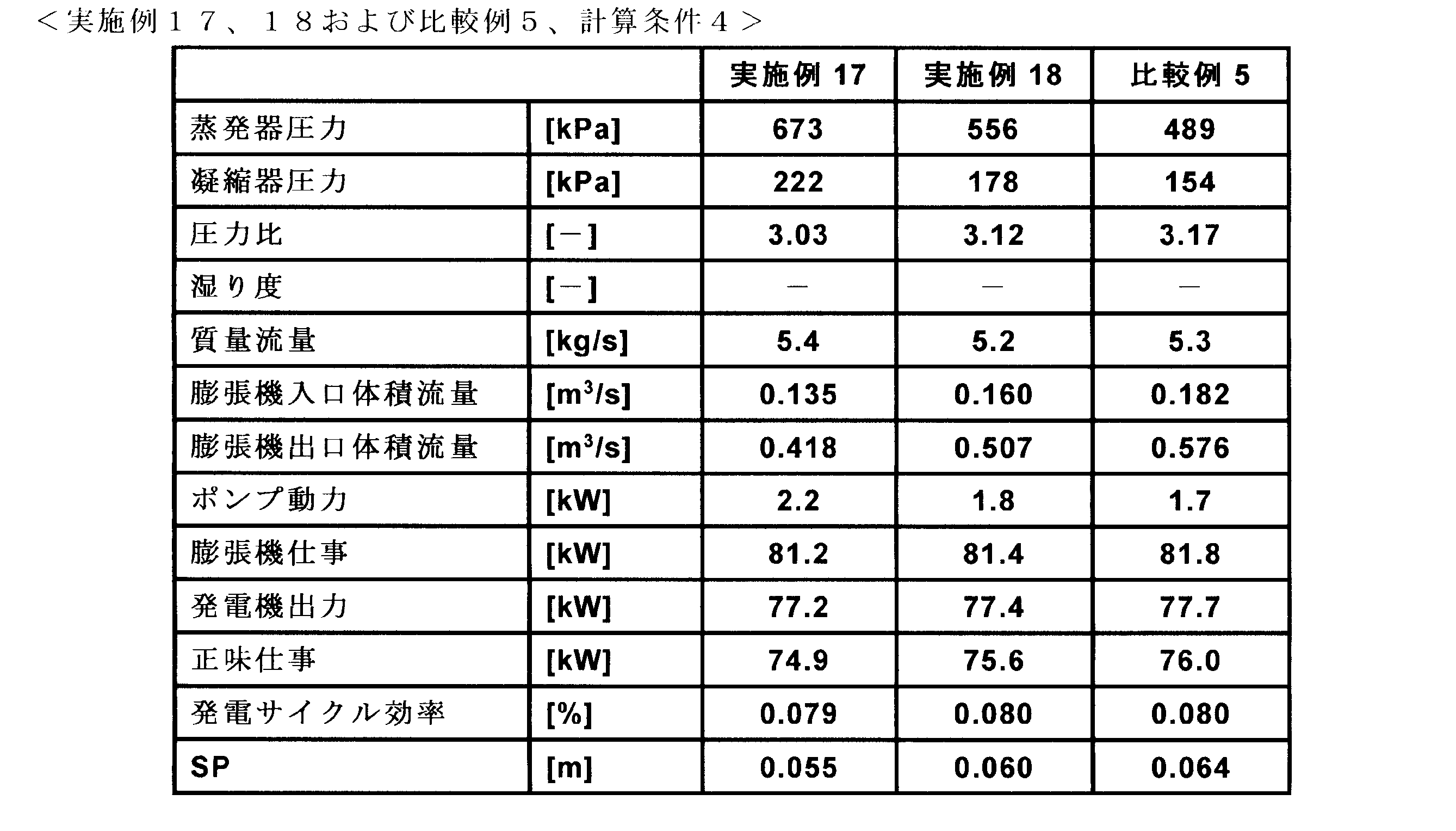
実施例19の有機ランキンサイクルシステム性能(ηcycleおよびSP)の算出結果を表19に示す。表19において、熱伝達媒体(作動媒体)の第1成分および第2成分の値は質量百分率で示す。熱伝達媒体(作動媒体)の第1成分がシス-2-クロロ-1,3,3,3-テトラフルオロプロペン(HCFO-1224xe(Z))であり、第2成分がトランス-2-クロロ-1,3,3,3-テトラフルオロプロペン(HCFO-1224xe(E))である。

表18に示した実施例17および18の膨張機入口体積流量、膨張機出口体積流量、発電サイクル効率およびSP値について、それぞれ比較例5の膨張機入口体積流量、膨張機出口体積流量、発電サイクル効率およびSP値を1として算出した相対値を表20に示す。
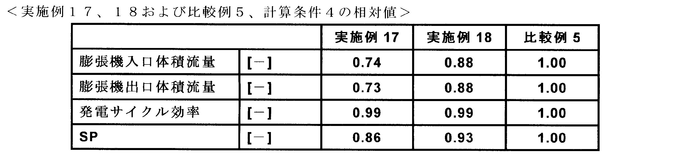
表19に示した実施例19の膨張機入口体積流量、膨張機出口体積流量、発電サイクル効率およびSP値について、それぞれ比較例5の膨張機入口体積流量、膨張機出口体積流量、発電サイクル効率およびSP値を1として算出した相対値を表21に示す。
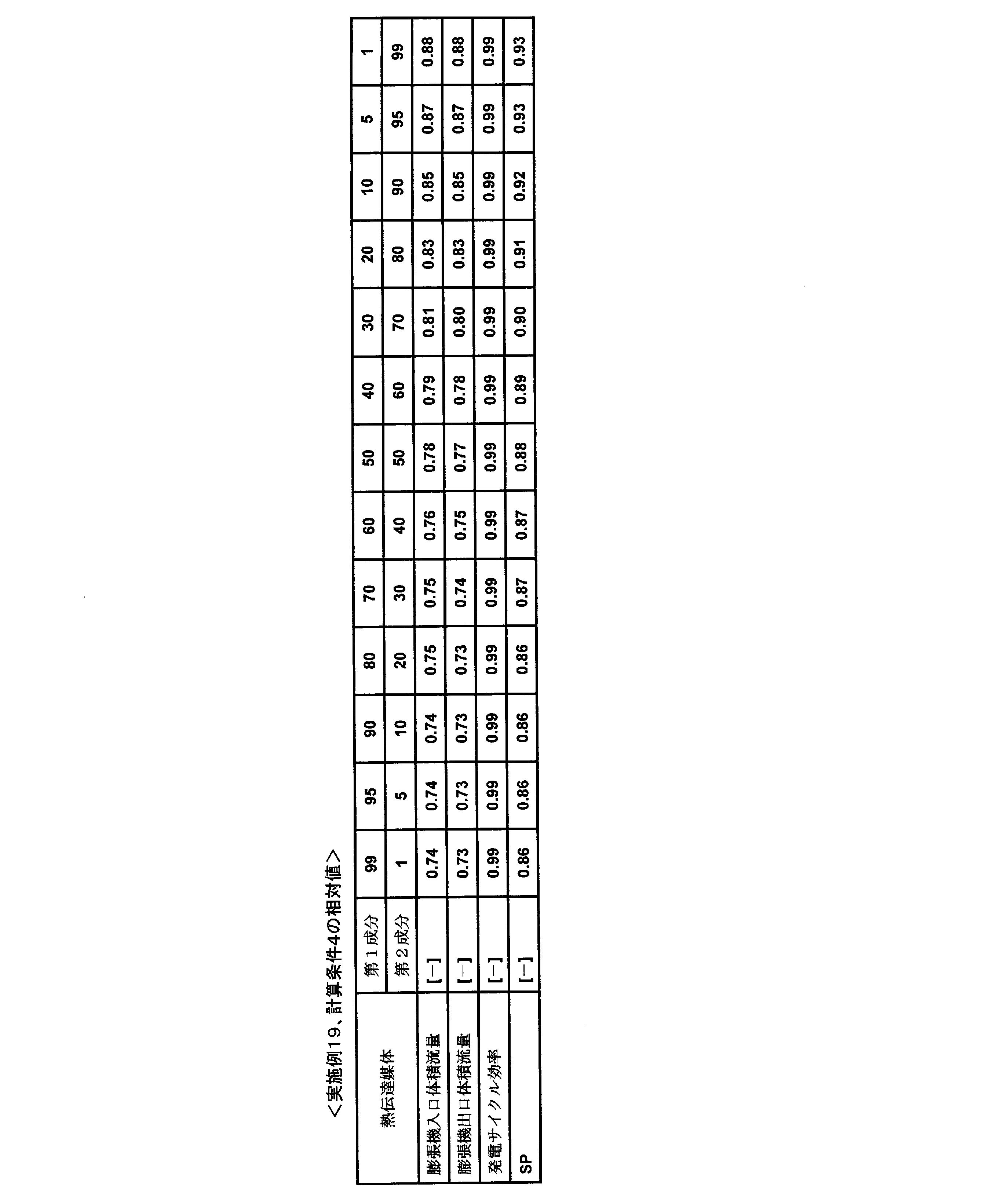
以上に説明した実施例20、21および比較例6の有機ランキンサイクルシステム性能(ηcycleおよびSP)の算出結果を表22に示す。

実施例22の有機ランキンサイクルシステム性能(ηcycleおよびSP)の算出結果を表23に示す。表23において、熱伝達媒体(作動媒体)の第1成分および第2成分の値は質量百分率で示す。熱伝達媒体(作動媒体)の第1成分がシス-2-クロロ-1,3,3,3-テトラフルオロプロペン(HCFO-1224xe(Z))であり、第2成分がトランス-2-クロロ-1,3,3,3-テトラフルオロプロペン(HCFO-1224xe(E))である。

表22に示した実施例20および21の膨張機入口体積流量、膨張機出口体積流量、発電サイクル効率およびSP値について、それぞれ比較例6の膨張機入口体積流量、膨張機出口体積流量、発電サイクル効率およびSP値を1として算出した相対値を表24に示す。
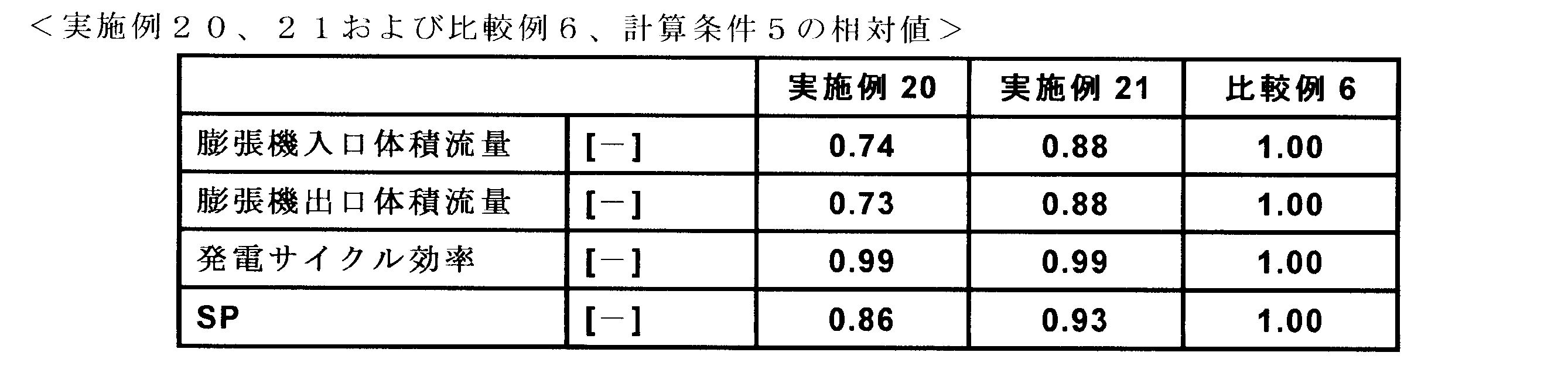
表23に示した実施例22の膨張機入口体積流量、膨張機出口体積流量、発電サイクル効率およびSP値について、それぞれ比較例6の膨張機入口体積流量、膨張機出口体積流量、発電サイクル効率およびSP値を1として算出した相対値を表25に示す。
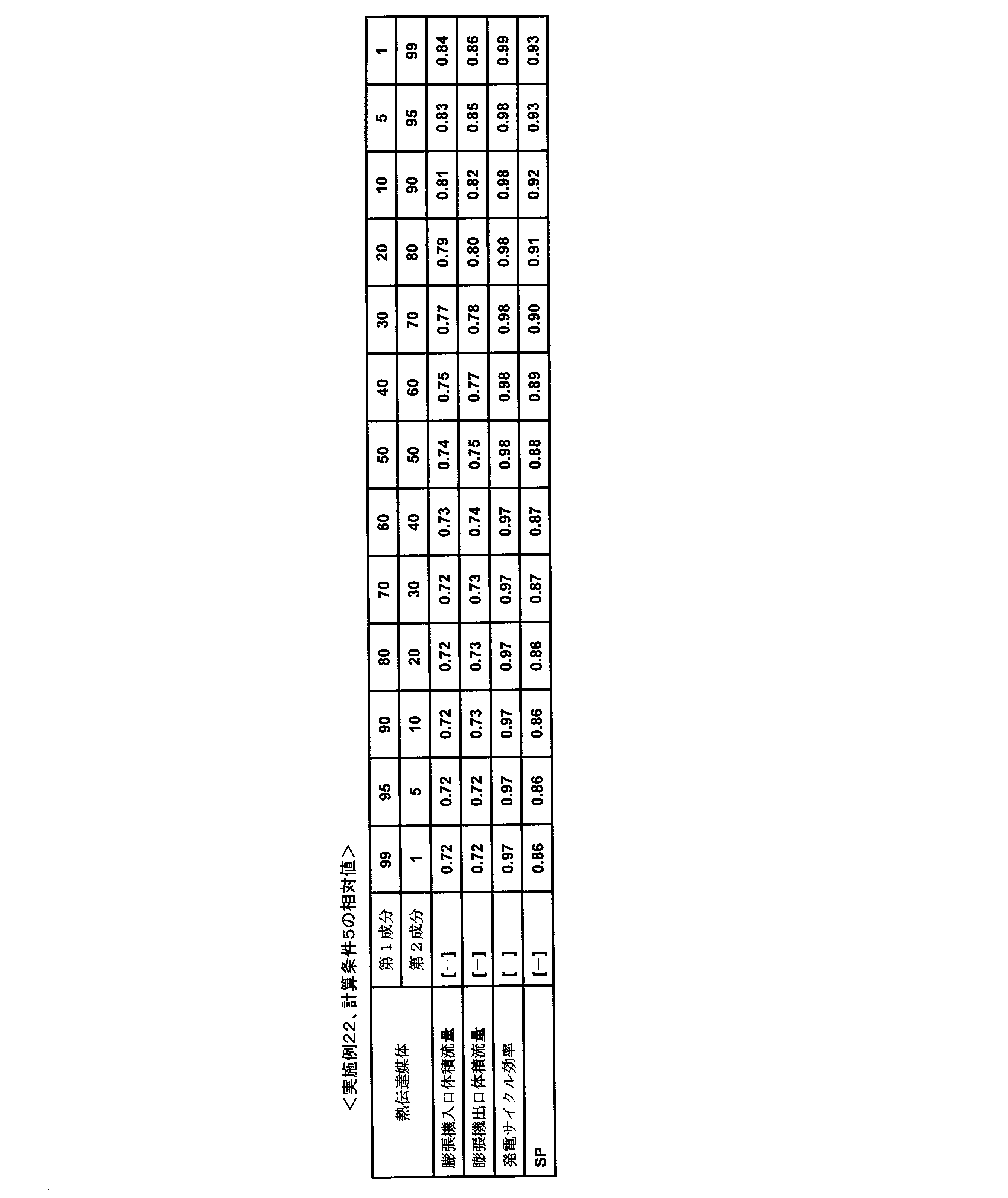
本発明の熱伝達媒体(作動媒体)である2-クロロ-1,3,3,3-テトラフルオロプロペン(HCFO-1224xe)と既存の作動媒体である2,2-ジクロロ-1,1,1-トリフルオロエタンとを比較すると、表18乃至表25に示す通り、有機ランキンサイクルシステムに適用したときの発電サイクル効率は、ほぼ同等であった。一方、膨張機サイズパラメータ(SP)は、本発明の熱伝達媒体(作動媒体)である2-クロロ-1,3,3,3-テトラフルオロプロペン(HCFO-1224xe)を用いた方が低い値となった。すなわち、本発明の熱伝達媒体(作動媒体)である2-クロロ-1,3,3,3-テトラフルオロプロペン(HCFO-1224xe)を60℃~170℃の熱エネルギーを機械エネルギー(および電気エネルギー)へ変換するための有機ランキンサイクルシステムに作動媒体として用いた場合、既存の2,2-ジクロロ-1,1,1-トリフルオロエタンを含む作動媒体よりもサイクル効率を維持しながら装置を小型化することが可能であることを意味する。
本発明の熱サイクル用熱伝達媒体は、不燃性かつ環境への負荷が小さい2-クロロ-1,3,3,3-テトラフルオロプロペン(HCFO-1224xe)を50質量%以上含む組成物であり、熱サイクル特性に優れ、冷凍サイクルシステム、高温ヒートポンプサイクルシステム、有機ランキンサイクルシステムの熱伝達媒体(作動媒体)として有用である。特に、遠心式圧縮機を備えた冷凍サイクルシステムに好適であり、地熱エネルギー、50~200℃程度の中低温度廃熱からの熱回収を目的とする高温ヒートポンプシステムにも好適である。また、前記中低温度廃熱の熱エネルギーを回収し、電気エネルギーへ変換するための有機ランキンサイクルシステムにも好適である。
11:蒸発器、12:圧縮機、13:凝縮器、14:膨張弁、100:冷凍サイクルシステムまたは高温ヒートポンプサイクルシステム、20:蒸発器、21:凝縮器、22:膨張機、23:循環ポンプ、24:発電機、200:有機ランキンサイクルシステム
Claims (16)
- 2-クロロ-1,3,3,3-テトラフルオロプロペンを50質量%以上含むことを特徴とする冷凍サイクルシステム、ヒートポンプサイクルシステムまたは有機ランキンサイクルシステム用の熱伝達媒体。
- 前記熱伝達媒体が、シス-2-クロロ-1,3,3,3-テトラフルオロプロペンを90質量%以上含むことを特徴とする請求項1に記載の熱伝達媒体。
- 前記熱伝達媒体が、2-クロロ-1,3,3,3-テトラフルオロプロペンのシス体およびトランス体の混合物であり、かつ前記2-クロロ-1,3,3,3-テトラフルオロプロペンのシス体とトランス体の質量比率において、シス体の質量比率が50質量%以上99.9質量%以下であり、トランス体の質量比率0.1質量%以上50質量%以下であることを特徴とする請求項1に記載の熱伝達媒体。
- 前記熱伝達媒体が潤滑油を含むことを特徴とする請求項1に記載の熱伝達媒体。
- 前記潤滑油が、パラフィン系油またはナフテン系油を含む鉱物油、または合成オイルであるアルキルベンゼン類(AB)、ポリ-α-オレフィン(PAO)、エステル類、ポリオールエステル類(POE)、ポリアルキレングリコール類(PAG)、ポリビニルエーテル類(PVE)およびそれらの組合せから選択されることを特徴とする請求項4に記載の熱伝達媒体。
- 前記熱伝達媒体が安定剤をさらに含むことを特徴とする請求項1に記載の熱伝達媒体。
- 前記安定剤が、ニトロ化合物、エポキシ化合物、フェノール類、イミダゾール類、アミン類、ジエン系化合物類、リン酸エステル類、芳香族不飽和炭化水素類、イソプレン類、プロパジエン類、テルペン類等およびそれらの組合せから選択されることを特徴とする請求項6に記載の熱伝達媒体。
- 請求項1に記載の熱伝達媒体を用いた冷凍サイクルシステム。
- 請求項1に記載の熱伝達媒体を用いたヒートポンプサイクルシステム。
- 請求項1に記載の熱伝達媒体を用いた有機ランキンサイクルシステム。
- 請求項1に記載の熱伝達媒体を気化させ、
前記熱伝達媒体を圧縮し、
前記熱伝達媒体を凝縮し、
前記熱伝達媒体を絞り膨張すること、
を含む、
前記熱伝達媒体を収容した冷凍サイクルシステムを用いた熱伝達方法。 - 請求項1に記載の熱伝達媒体を気化させ、
前記熱伝達媒体を圧縮し、
前記熱伝達媒体を凝縮し、
前記熱伝達媒体を絞り膨張すること、
を含む、
前記熱伝達媒体を収容した高温ヒートポンプサイクルシステムを用いた熱伝達方法。 - 請求項1に記載の熱伝達媒体を気化させ、
前記熱伝達媒体を膨張させ、
前記熱伝達媒体を凝縮し、
前記熱伝達媒体をポンプで昇圧して移送すること、
を含む、
前記熱伝達媒体を収容した有機ランキンサイクルシステムを用いた熱エネルギーを機械エネルギーへ変換する方法。 - 2,2-ジクロロ-1,1,1-トリフルオロエタンを含む熱伝達媒体を使用する冷凍サイクルシステムに、請求項1に記載の熱伝達媒体を供給すること、
を含む冷凍サイクルシステムにおいて熱伝達媒体を置換える方法。 - 2,2-ジクロロ-1,1,1-トリフルオロエタンを含む熱伝達媒体を使用する高温ヒートポンプサイクルシステムに、請求項1に記載の熱伝達媒体を供給すること、
を含む高温ヒートポンプサイクルシステムにおいて熱伝達媒体を置換える方法。 - 2,2-ジクロロ-1,1,1-トリフルオロエタンを含む熱伝達媒体を使用する有機ランキンサイクルシステムに、請求項1に記載の熱伝達媒体を供給すること、
を含む有機ランキンサイクルシステムにおいて熱伝達媒体を置換える方法。
Applications Claiming Priority (2)
| Application Number | Priority Date | Filing Date | Title |
|---|---|---|---|
| JP2014-261295 | 2014-12-24 | ||
| JP2014261295A JP6435854B2 (ja) | 2014-12-24 | 2014-12-24 | 2−クロロ−1,3,3,3−テトラフルオロプロペンを含む熱伝達媒体 |
Publications (1)
| Publication Number | Publication Date |
|---|---|
| WO2016104287A1 true WO2016104287A1 (ja) | 2016-06-30 |
Family
ID=56150310
Family Applications (1)
| Application Number | Title | Priority Date | Filing Date |
|---|---|---|---|
| PCT/JP2015/085224 Ceased WO2016104287A1 (ja) | 2014-12-24 | 2015-12-16 | 2-クロロ-1,3,3,3-テトラフルオロプロペンを含む熱伝達媒体 |
Country Status (2)
| Country | Link |
|---|---|
| JP (1) | JP6435854B2 (ja) |
| WO (1) | WO2016104287A1 (ja) |
Cited By (1)
| Publication number | Priority date | Publication date | Assignee | Title |
|---|---|---|---|---|
| CN110878198A (zh) * | 2018-09-06 | 2020-03-13 | 陕西久维电力工程有限公司 | 一种储存太阳能热量的相变材料及其制备方法、应用 |
Families Citing this family (3)
| Publication number | Priority date | Publication date | Assignee | Title |
|---|---|---|---|---|
| JP7108599B2 (ja) * | 2017-03-17 | 2022-07-28 | Agc株式会社 | 熱サイクルシステム用組成物および熱サイクルシステム |
| JP7190693B2 (ja) * | 2018-11-02 | 2022-12-16 | 東芝キヤリア株式会社 | 圧縮機及び冷凍サイクル装置 |
| JP7812768B2 (ja) * | 2022-10-05 | 2026-02-10 | 株式会社日立産機システム | 圧縮空気エネルギ貯蔵装置 |
Citations (4)
| Publication number | Priority date | Publication date | Assignee | Title |
|---|---|---|---|---|
| JP2013249326A (ja) * | 2012-05-30 | 2013-12-12 | Central Glass Co Ltd | フルオロアルケンを含有する熱伝達媒体 |
| JP2014005418A (ja) * | 2012-06-27 | 2014-01-16 | Central Glass Co Ltd | フッ素化不飽和炭化水素を含む熱伝達媒体 |
| JP2014005419A (ja) * | 2012-06-27 | 2014-01-16 | Central Glass Co Ltd | フッ素化エーテルを含む熱伝達作動媒体 |
| WO2014102479A1 (fr) * | 2012-12-26 | 2014-07-03 | Arkema France | Composition comprenant du 2,3,3,3-tetrafluoropropene |
-
2014
- 2014-12-24 JP JP2014261295A patent/JP6435854B2/ja active Active
-
2015
- 2015-12-16 WO PCT/JP2015/085224 patent/WO2016104287A1/ja not_active Ceased
Patent Citations (4)
| Publication number | Priority date | Publication date | Assignee | Title |
|---|---|---|---|---|
| JP2013249326A (ja) * | 2012-05-30 | 2013-12-12 | Central Glass Co Ltd | フルオロアルケンを含有する熱伝達媒体 |
| JP2014005418A (ja) * | 2012-06-27 | 2014-01-16 | Central Glass Co Ltd | フッ素化不飽和炭化水素を含む熱伝達媒体 |
| JP2014005419A (ja) * | 2012-06-27 | 2014-01-16 | Central Glass Co Ltd | フッ素化エーテルを含む熱伝達作動媒体 |
| WO2014102479A1 (fr) * | 2012-12-26 | 2014-07-03 | Arkema France | Composition comprenant du 2,3,3,3-tetrafluoropropene |
Cited By (2)
| Publication number | Priority date | Publication date | Assignee | Title |
|---|---|---|---|---|
| CN110878198A (zh) * | 2018-09-06 | 2020-03-13 | 陕西久维电力工程有限公司 | 一种储存太阳能热量的相变材料及其制备方法、应用 |
| CN110878198B (zh) * | 2018-09-06 | 2021-05-18 | 陕西久维电力工程有限公司 | 一种储存太阳能热量的相变材料及其制备方法、应用 |
Also Published As
| Publication number | Publication date |
|---|---|
| JP2016121248A (ja) | 2016-07-07 |
| JP6435854B2 (ja) | 2018-12-12 |
Similar Documents
| Publication | Publication Date | Title |
|---|---|---|
| JP6213194B2 (ja) | 熱エネルギーを機械エネルギーへ変換する方法、有機ランキンサイクル装置、及び作動流体を置換える方法 | |
| JP6299763B2 (ja) | 熱伝達方法および高温ヒートポンプ装置 | |
| JP6138194B2 (ja) | 熱伝達方法 | |
| JP6432341B2 (ja) | 共沸混合物様の組成物、熱伝達組成物、洗浄剤、高温ヒートポンプ装置、冷凍サイクルシステム及び熱伝達方法 | |
| US10101065B2 (en) | Heat transmission method and high-temperature heat pump device | |
| JP6138957B2 (ja) | 冷媒循環装置、冷媒循環方法および酸抑制方法 | |
| CN103923723A (zh) | 氟代烯烃制冷剂组合物 | |
| CN106574802A (zh) | 热循环系统 | |
| CN106414653A (zh) | 热循环系统用组合物以及热循环系统 | |
| CN107532070A (zh) | 热循环系统用组合物以及热循环系统 | |
| JP6381890B2 (ja) | 冷媒循環装置、冷媒循環方法および異性化抑制方法 | |
| JP2015196702A (ja) | 1−クロロ−3,3,3−トリフルオロプロペン及び1,1,1,3,3−ペンタフルオロプロパンを含有する共沸乃至共沸様組成物 | |
| JP6435854B2 (ja) | 2−クロロ−1,3,3,3−テトラフルオロプロペンを含む熱伝達媒体 | |
| JP2015083899A5 (ja) | ||
| CN107532073A (zh) | 热循环系统用组合物以及热循环系统 | |
| JP6468331B2 (ja) | 熱エネルギーを機械エネルギーへ変換する方法、有機ランキンサイクル装置、及び作動流体を置換える方法 | |
| CN102803429B (zh) | 用于高温传热的制冷剂 | |
| WO2026070778A1 (ja) | 熱サイクル用作動媒体、熱サイクルシステム用組成物、及び熱サイクルシステム | |
| WO2026070777A1 (ja) | 熱サイクル用作動媒体、熱サイクルシステム用組成物、及び熱サイクルシステム | |
| US9732262B2 (en) | Compositions of 2,4,4,4-tetrafluorobut-1-ene and 1-methoxyheptafluoropropane |
Legal Events
| Date | Code | Title | Description |
|---|---|---|---|
| 121 | Ep: the epo has been informed by wipo that ep was designated in this application |
Ref document number: 15872856 Country of ref document: EP Kind code of ref document: A1 |
|
| NENP | Non-entry into the national phase |
Ref country code: DE |
|
| 122 | Ep: pct application non-entry in european phase |
Ref document number: 15872856 Country of ref document: EP Kind code of ref document: A1 |