WO2016104147A1 - 冷凍又は空調装置及びその制御方法 - Google Patents
冷凍又は空調装置及びその制御方法 Download PDFInfo
- Publication number
- WO2016104147A1 WO2016104147A1 PCT/JP2015/084522 JP2015084522W WO2016104147A1 WO 2016104147 A1 WO2016104147 A1 WO 2016104147A1 JP 2015084522 W JP2015084522 W JP 2015084522W WO 2016104147 A1 WO2016104147 A1 WO 2016104147A1
- Authority
- WO
- WIPO (PCT)
- Prior art keywords
- refrigerant
- gas
- stages
- heat exchanger
- temperature
- Prior art date
- Legal status (The legal status is an assumption and is not a legal conclusion. Google has not performed a legal analysis and makes no representation as to the accuracy of the status listed.)
- Ceased
Links
Images





Classifications
-
- F—MECHANICAL ENGINEERING; LIGHTING; HEATING; WEAPONS; BLASTING
- F25—REFRIGERATION OR COOLING; COMBINED HEATING AND REFRIGERATION SYSTEMS; HEAT PUMP SYSTEMS; MANUFACTURE OR STORAGE OF ICE; LIQUEFACTION SOLIDIFICATION OF GASES
- F25B—REFRIGERATION MACHINES, PLANTS OR SYSTEMS; COMBINED HEATING AND REFRIGERATION SYSTEMS; HEAT PUMP SYSTEMS
- F25B1/00—Compression machines, plants or systems with non-reversible cycle
-
- F—MECHANICAL ENGINEERING; LIGHTING; HEATING; WEAPONS; BLASTING
- F25—REFRIGERATION OR COOLING; COMBINED HEATING AND REFRIGERATION SYSTEMS; HEAT PUMP SYSTEMS; MANUFACTURE OR STORAGE OF ICE; LIQUEFACTION SOLIDIFICATION OF GASES
- F25B—REFRIGERATION MACHINES, PLANTS OR SYSTEMS; COMBINED HEATING AND REFRIGERATION SYSTEMS; HEAT PUMP SYSTEMS
- F25B1/00—Compression machines, plants or systems with non-reversible cycle
- F25B1/10—Compression machines, plants or systems with non-reversible cycle with multi-stage compression
Definitions
- the present invention relates to a refrigeration or air conditioner using a reverse Ericsson cycle as a refrigeration cycle and a control method thereof.
- the theoretical reverse Ericsson cycle consists of two isothermal processes and two isobaric processes, which are heat exchange processes.
- refrigeration cycle components such as a compressor, a condenser, an expansion valve and an evaporator provided in series in a refrigerant circuit, gas refrigerant and condensation from the evaporator outlet toward the compressor inlet
- a reverse Ericsson cycle similar to the theoretical reverse Ericsson cycle is possible.
- Patent Document 1 discloses a refrigeration or air conditioning system using the above-mentioned approximate reverse Ericsson cycle.
- this approximate reverse Ericsson cycle the partial stroke of the isothermal compression performed in the superheated steam region in the isothermal heat release stroke is replaced by a multistage adiabatic compression stroke and a multistage isostatic heat release stroke, and the regenerative heat exchanger inlet from the evaporator outlet
- the thermal efficiency can be improved by controlling the dryness of the gas refrigerant flowing into the
- Patent No. 4726258 gazette
- the specific heat of the gas refrigerant is smaller than that of the liquid refrigerant, so there is a tendency for the liquid refrigerant side to be insufficiently supercooled, and improvement in thermal efficiency can not be expected much
- the thermal efficiency is to be improved by controlling the dryness (wetness) of the gas refrigerant flowing from the evaporator into the regenerative heat exchanger. It is difficult to control the refrigerant state at the outlet of the evaporator accurately to the appropriate wet state. Since the optimum control point is only one point, the coefficient of performance of the cycle decreases even if the refrigerant state at the outlet of the evaporator is too wet or too wet.
- At least one embodiment of the present invention aims to make it possible to further improve the thermal efficiency in a refrigeration or air conditioning system using the aforementioned approximate reverse Ericsson cycle.
- a refrigeration or air conditioner is (1) a plurality of stages of compressors, a condenser, a first expansion means, and an evaporator provided in series in the refrigerant circulation path;
- a gas cooler for cooling the discharge gas refrigerant of each compressor, provided in the refrigerant circulation path connecting the outlet of each compressor and the inlet of the compressor of the next stage with the plurality of stages of compressors;
- a regenerative heat exchanger for exchanging heat between the low pressure side gas refrigerant traveling from the evaporator to the compressor and the high pressure side liquid refrigerant traveling from the condenser to the first expansion means.
- a reverse Ericsson cycle which comprises an isothermal heat release process mainly by the condenser, an isothermal heat absorption process by the evaporator, an isobaric heat release process by the high pressure side liquid refrigerant in the regenerative heat exchanger, and an equal pressure heat absorption process by the low pressure side gas refrigerant.
- a partial stroke of isothermal compression performed in the superheated steam region of the isothermal heat release stroke is replaced with a plurality of adiabatic compression strokes by the plurality of compressors and a plurality of equal pressure heat release strokes by the gas cooler.
- An approximate isothermal process is formed by The low pressure side gas refrigerant in a wet state was introduced to the regenerative heat exchanger at the start point of the isothermal heat absorption stroke, and the low pressure side gas refrigerant in a saturated state was introduced to the regeneration heat exchanger at the start point of the equal pressure heat absorption stroke.
- the controller is further provided with a control device for controlling the end point of the equal pressure heat-releasing stroke to be located within the subcooling region up to the wet limit supercooling point where the heat release stroke ends.
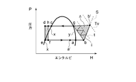
- FIG. 1 is a schematic view of a reverse Ericsson cycle in a TS diagram
- FIG. 2 is a schematic view of the reverse Ericsson cycle in a Mollier diagram. 1 and 2, the symbol x is a saturated liquid line of the refrigerant, y is a saturated vapor line of the refrigerant, t is an isotherm, Tv is the discharge temperature of the single-stage compressor, and the broken line p in FIG.
- a broken line S in FIG. 2 indicates an isentropic line corresponding to the vertical line bb 'in FIG.
- the theoretical reverse Ericsson cycle is indicated by abgcda (solid line).
- the theoretical reverse Ericsson cycle consists of two isothermal strokes (d ⁇ a and b ⁇ c) and two equal pressure strokes (a ⁇ b and c ⁇ d).
- Two equal pressure strokes ab and cd are heat exchange processes in the regenerative heat exchanger.
- the partial isothermal stroke (b ⁇ g) is a theoretical isothermal compression stroke. In the practical cycle, it is necessary to replace the adiabatic compression stroke (b.fwdarw.b ') and the equal pressure radiation stroke (b'.fwdarw.g), so that an additional compression work .DELTA.
- the equal pressure stroke b'g is carried out by means of a gas cooler.
- the partial stroke (isothermal stroke b ⁇ g) performed in the superheated steam region of the above-described equal pressure heat radiation stroke is divided into adiabatic compression strokes of multiple stages by multiple stages of compressors, and gas It is possible to approximate an isothermal process (b ⁇ g) by replacing the cooler and the sensible heat portion of the final stage with a plurality of stages of equal pressure heat dissipating processes with a condenser for cooling.
- the compression work ⁇ can be reduced, and the COP (coefficient of performance) can be improved.
- An outlet point d at which the liquid refrigerant outlet temperature of the regenerative heat exchanger is equal to the evaporation temperature is defined as a "wet limit supercooling point".
- the opening degree of the first expansion means for example, expansion valve
- the opening degree of the first expansion means may be increased to increase the amount of liquid supplied to the evaporator.
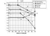
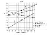
- FIG. 3 and 4 show the relationship between the regenerative heat exchanger and coefficient of performance of the reverse Ericsson cycle using a single-stage compression stroke and a single-stage expansion stroke.
- the vertical axes of the figures show the coefficient of performance (COP), and the horizontal axes show the liquid refrigerant outlet temperature (FIG. 3) and the gas refrigerant outlet temperature (FIG. 4) of the regenerative heat exchanger.
- the display symbols such as ⁇ , ⁇ , ⁇ , ⁇ on the graph line indicate the positions of theoretical calculation points and do not indicate experimental results. This characteristic forms the main part of the present invention, and will be described in some detail below taking the refrigerant R600a (isobutane) of symbol B as an example.
- FIG. 3 shows the characteristics of the liquid side refrigerant of the regenerative heat exchanger separately for the refrigerant.
- a point c (state point c in FIGS. 1 and 2) on the liquid refrigerant outlet temperature 40 ° C. indicates the degree of subcooling, ie, COP in a state where the regenerative heat exchanger is not used.
- the performance at point d (state point d in FIGS. 1 and 2) on the liquid refrigerant outlet temperature ⁇ 40 ° C. indicates COP at the maximum subcooling temperature. From FIG. 3, when the outlet temperature of the liquid refrigerant in the regenerative heat exchanger is known, the COP at that time can be known.
- the outlet temperature of the liquid refrigerant is uniquely determined by the inlet temperature and the degree of humidity of the gas refrigerant. For example, if the gas refrigerant inlet is in a saturated gas state, the liquid refrigerant outlet is at point h (state point h in FIGS. 1 and 2), and COP is at a maximum. At that time, the solution temperature is about -13 ° C. according to FIG. This state point h is the aforementioned "sensible heat limit supercooling point".
- the subcooling temperature of the liquid refrigerant can be lowered to the state point d ( ⁇ 40 ° C.).
- the state point d is the "wet limit supercooling point”.
- the inlet point of the gas refrigerant at this time (state point a 'in FIGS. 1 and 2) is defined as "wetness limit point a'".
- the degree of wetness of the gas refrigerant inlet is increased above the wet limit point a ′, the temperature of the liquid refrigerant outlet remains unchanged, and the COP is lowered.
- the temperature of the gas refrigerant inlet reaches an overheat temperature of ⁇ 40 ° C. or more, the liquid refrigerant outlet state has a higher temperature than the state point h, and therefore, the COP is lower than the result of FIG.
- FIG. 4 shows the characteristics of the gas side refrigerant of the regenerative heat exchanger separately for the refrigerant.
- COP on the temperature -40 ° C line is a saturated gas state a at the gas refrigerant inlet of the regenerative heat exchanger at -40 ° C (state point a in Figs. 1 and 2) and a saturated gas state at the gas refrigerant outlet -40 ° C This indicates the COP when in the state, in other words, the COP when the regenerative heat exchanger is not used.
- COP at point b (state point b in FIG. 1 and FIG. 2) on the gas refrigerant outlet temperature 40 ° C.
- FIG. 4 is COP when the liquid refrigerant outlet temperature becomes “sensible heat limit supercooling point h” in FIG. 1 and FIG. Indicates From FIG. 4, when the outlet temperature of the gas refrigerant of the regenerative heat exchanger is known, the COP at that time can be known immediately. As the outlet temperature of the gas refrigerant decreases from the condensation temperature of 40 ° C., the COP decreases.
- the performance improvement effect by the regenerative heat exchanger is This means that the difference is maximum when the sensible heat difference between the inlet (saturated) and the outlet (superheated) is used to the maximum.
- the outlet temperature of the liquid refrigerant is uniquely determined by the inlet temperature and the humidity of the gas refrigerant. The problem is that the influence of the inlet humidity of the gas refrigerant is not shown at all in FIG. The reason is that even if the humidity of the gas refrigerant inlet moves from the state a in FIGS.
- the inlet temperature is constant (evaporation temperature), so the influence of the humidity on the coordinates in FIG. Because there is no way to show that. From this, maintaining the inlet of the gas refrigerant of the regenerative heat exchanger in a wet state is irrelevant to theoretical performance improvement, but has important meaning from the viewpoint of the control method for maximizing the COP. This will be described later.
- the theoretical coefficient of performance of the conventional refrigeration cycle is COPtc (COP of each refrigerant at 40 ° C in Fig. 3 and COP of each refrigerant at -40 ° C in Fig. 4), the theoretical coefficient of performance of the reverse Ericsson cycle is COPte (the above (1)
- COPteh the broken line COP in (2) above
- the actual coefficient of performance of the conventional refrigeration cycle under the same operating conditions is COPpc
- Ericsson cycle Let COPpe be the actual machine performance coefficient of.
- the actual performance coefficient COPpe of the Ericsson cycle can be predicted from the following equation using the actual performance coefficient COPpc of the conventional cycle.
- COP los in the formula (c) represents the amount of COP loss due to the regenerative heat exchanger loss.
- the actual machine performance prediction value according to equation (a) has an error of 1%. There is no possibility of exceeding, and it can be considered to be within the accuracy range of the experimental results.
- the solid line coefficient of performance (COP) of the refrigerant R 600 a indicates the performance when the heat transfer loss of the regenerative heat exchanger is zero.
- the supercooling temperature reaches -40.degree. C.
- Td -40.degree. C.
- COP 2.30, respectively.
- the performance when the temperature difference between the liquid refrigerant and the gas refrigerant at the cold end side and the warm end side inlet / outlet is set to 5 ° C. is shown by a horizontal broken line in consideration of the heat transfer loss of the regenerative heat exchanger.
- the performance other than the broken line is indicated by a single solid line because the performance is the same regardless of the heat transfer loss.
- the temperature range of the liquid side refrigerant is ⁇ 35 ° C. to 40 ° C.
- the temperature range of the gas side refrigerant is ⁇ 40 ° C. to 35 ° C. Since the cold end side temperature difference of the regenerative heat exchanger is 5 ° C., the liquid refrigerant outlet temperature in FIG.
- the “sensible heat limit supercooling point” moves to the high temperature side and the maximum COP decreases as the heat transfer loss of the regenerative heat exchanger increases.
- Refrigerant A (R717: ammonia) has cycle performance significantly different from that of the other exemplified refrigerants in a reverse Ericsson cycle having a single-stage compression stroke and a single-stage expansion stroke. That is, the performance is rapidly reduced due to the subcooling of the liquid refrigerant by the regenerative heat exchanger.
- the description is omitted because it deviates from the gist of the present invention, it is possible to improve the performance to the same extent as that of the refrigerant R600a even with the refrigerant R717 by increasing the number of compression stages and the number of expansion stages.
- the adiabatic compression strokes of the plurality of stages Let the compression ratio r between multiple stages of compressors be (Pc / Pe) 1 / n ,
- the control device is configured to cool the inlet gas refrigerant (condensing temperature + ⁇ ) to a temperature close to the condensing temperature in the plurality of stages of equal-pressure heat release strokes by the gas cooler.
- ⁇ is a temperature rising range by compression of the suction gas of each stage compressor, and ⁇ can be decreased by increasing the number of stages. For this reason, ⁇ should be selected in consideration of the mechanical use temperature range of the compressor and the performance improvement by multistage formation.
- the compression ratio r between the plurality of stages of compressors is set to (Pc / Pe) 1 / n .
- the discharge pressure and the discharge temperature of the gas refrigerant can be made substantially equal, and the protrusion of the discharge pressure and the discharge temperature can be suppressed in some compressors. By this, it is possible to suppress the deterioration of the lubricating oil and the burning of the packing material and the like.
- a first liquid gas separator provided in the refrigerant circuit between the regenerative heat exchanger and the first expansion means;
- a second expansion means provided in the refrigerant circulation path on the inlet side of the first liquid gas separator;
- the enthalpy difference is increased by providing the intermediate cooling device, and the corresponding change in total compression work occurs, but as a result, the COP is improved. Therefore, the COP of the refrigeration or air conditioner can be further improved.
- a second liquid gas separator provided in the refrigerant circuit between the regenerative heat exchanger and the first expansion means; Third expansion means provided in the refrigerant circuit at the inlet side of the second liquid gas separator;
- An economizer device further comprising: an economizer gas line for supplying gas refrigerant of the second liquid gas separator to an intermediate pressure region of the lower stage compressor among the plurality of stages of compressors.
- the number of stages of the plurality of stages of compressors is two or three.
- the number of stages of the plurality of stages of compressors is four or more, two stages or three stages become a practical number of stages because they do not contribute to the improvement of COP in spite of the increase in equipment cost.
- a control method of a refrigeration or air conditioner (6) A plurality of stages of compressors, a condenser, a first expansion means, and an evaporator provided in series in the refrigerant circulation path; A gas cooler for cooling the discharge gas refrigerant of each compressor, provided in the refrigerant circulation path connecting the outlet of each compressor and the inlet of the next compressor with the plurality of stages of compressors; A control method of a refrigeration or air conditioner comprising: a regenerative heat exchanger for exchanging heat between a gas refrigerant traveling from the evaporator toward the compressor and a liquid refrigerant traveling from the condenser toward the first expansion means, A reverse Ericsson including an isothermal heat release process mainly by the condenser, an isothermal heat absorption process by the evaporator, an isobaric heat release process in a liquid area performed by heat exchange in the regenerative heat exchanger, and an isobaric heat absorption process in
- the partial stroke performed in the superheated steam region of the isothermal heat release stroke is replaced with a plurality of adiabatic compression strokes by the plurality of stages of compressors and a plurality of equal pressure heat release strokes by the gas cooler and the condenser.
- the first process The refrigerant in a wet state in the equal pressure heat absorption process is introduced into the regenerative heat exchanger, and the saturated gas refrigerant is introduced into the regenerative heat exchanger in the equal pressure heat absorption process, which is the end point of the isothermal heat release process Supercooling of the region from the sensible heat limit supercooling point to the wetness limit supercooling point where the end point of the adiabatic expansion stroke by the first expansion means is located on the saturated refrigerant liquid line and the end point of the isothermal heat release stroke And a second step of controlling the end point of the isothermal heat-releasing stroke at a point.
- the practical cycle can be brought close to the theoretical reverse Ericsson cycle by the first process, COP can be improved and temperature increase of the gas refrigerant can be suppressed.
- burning of the elastomer constituting the packing material and the like can be prevented.
- the COP of the refrigeration or air conditioner can be maintained at the maximum, and the optimum control conditions are not point setting but range setting, and control is extremely easy.
- the second stroke is performed by controlling the number of revolutions of a motor driving at least the plurality of stages of compressors and controlling the first expansion means.
- the COP can be improved by the simple control conventionally performed.
- the second process is A first step of detecting a temperature of the liquid refrigerant at the outlet of the regenerative heat exchanger from the condenser toward the first expansion means; Controlling the temperature detection value detected in the first step to a temperature between the refrigerant temperature at the sensible heat limit supercooling point and the evaporation temperature of the refrigerant in the evaporator.
- the sensible heat limit overcooling point or the wet limit overcooling point can be easily determined from the detection values of the temperature sensor provided in the evaporator or the regenerative heat exchanger. .
- FIG. 5 is a TS diagram of an approximate reverse Ericsson cycle. It is a Mollier diagram of an approximate reverse Ericsson cycle. It is a diagram which shows the liquid refrigerant exit temperature of a regeneration heat exchanger, and the relationship of COP. It is a diagram which shows the relationship between the gas refrigerant exit temperature of a regeneration heat exchanger, and COP. It is a systematic diagram of a freezing device concerning one embodiment.
- FIG. 6 is a TS diagram showing an approximate reverse Ericsson cycle of the refrigeration system shown in FIG. 5; It is a systematic diagram of a freezing device concerning one embodiment. It is a TS diagram which shows the approximate reverse Ericsson cycle of the freezing apparatus shown in FIG.
- FIG. 11 is a TS diagram showing an approximate reverse Ericsson cycle of the refrigeration apparatus shown in FIG. 10; It is a systematic diagram of a freezing device concerning one embodiment. It is a systematic diagram of a freezing device concerning one embodiment. It is a TS diagram which shows the approximate reverse Ericsson cycle which the refrigerating apparatus shown in FIG. 13 comprises. It is a chart showing COP (calculation value) of a freezing apparatus concerning the embodiment.
- FIG. 6 is a diagram showing COPs of an approximate reverse Ericsson cycle and a conventional refrigeration cycle.
- expressions that indicate that things such as “identical”, “equal” and “homogeneous” are equal states not only represent strictly equal states, but also have tolerances or differences with which the same function can be obtained. It also represents the existing state.
- expressions representing shapes such as quadrilateral shapes and cylindrical shapes not only represent shapes such as rectangular shapes and cylindrical shapes in a geometrically strict sense, but also uneven portions and chamfers within the range where the same effect can be obtained. The shape including a part etc. shall also be expressed.
- the expressions “comprising”, “having”, “having”, “including” or “having” one component are not exclusive expressions excluding the presence of other components.
- FIG. 5 to 12 show several embodiments of the refrigeration or air conditioning device according to the present invention.
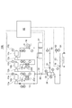
- FIG. 5 shows a refrigeration system 10A that performs three-stage compression and three-stage expansion
- FIG. 6 is a TS diagram of an approximate reverse Ericsson cycle configured by the refrigeration system 10A
- FIG. 7 shows a refrigeration system 10B that performs three-stage compression and two-stage expansion
- FIG. 8 is a TS diagram of an approximate reverse Ericsson cycle configured by the refrigeration apparatus 10B
- FIG. 9 is a Mollier wire of the approximate reverse Ericsson cycle.
- FIG. FIG. 10 shows a refrigeration system 10C that performs three-stage compression single-stage expansion
- FIG. 11 is a TS diagram of an approximate reverse Ericsson cycle configured by the refrigeration system 10C
- FIG. 12 shows a refrigeration system 10D that performs three-stage compression and two-stage expansion.
- Refrigerating apparatuses 10A to 10D shown in FIGS. 5 to 12 have a plurality of stages (three stages) of compressors 13a, 13b and 13c, a condenser 16, a first expansion valve 18, and evaporation which constitute a refrigeration cycle in a refrigerant circuit 12.
- the vessels 20 are provided in series.
- Each compressor is rotationally driven by the electric motors 14a, 14b and 14c, respectively.
- a positive displacement compressor such as a screw compressor is used.
- turbo compressors may be used in applications where fluctuations in operating conditions are small.
- the gas refrigerant paths 12a and 12b connecting the outlet and the inlet of each compressor are provided with gas coolers 22a and 22b for cooling the gas refrigerant discharged from the compressor 13a or 13b with a cooling medium such as cooling water.
- the regenerative heat exchanger 24 for heat-exchanging the gas refrigerant which goes to the compressor 13a from the evaporator 20 and the liquid refrigerant which came out of the condenser 16 is provided.
- a first liquid gas separator 28 provided in the refrigerant circuit 12 between the regenerative heat exchanger 24 and the first expansion valve 18, and a first liquid gas separator
- the second expansion valve 30 provided in the refrigerant circulation passage 12 on the inlet side of 28 and the gas refrigerant separated from the liquid refrigerant by the first liquid gas separator 28 are discharged from the first stage compressor 13a and the second stage compression It further comprises an intercooler 26 having an intermediate gas path 32 supplying the refrigerant path 12a connected to the inlet of the machine 13b.
- the intermediate gas passage 32 is connected to the refrigerant passage 12a on the downstream side of the gas cooler 22a.
- a second liquid gas separator 36 provided in the refrigerant circuit 12 between the regenerative heat exchanger 24 and the first expansion valve 18, and a second liquid gas separator
- a third expansion valve 38 provided in the refrigerant circulation passage 12 on the inlet side of 36, and an economizer gas passage 40 for supplying the gas refrigerant of the second liquid gas separator 36 to the intermediate pressure region of the first stage compressor 13a
- the system further comprises an economizer device 34.
- the liquid refrigerant of the first liquid gas separator 28 is supplied to the second liquid gas separator 36 through the refrigerant circuit 12.
- the regenerative heat exchanger 24 to the refrigerant circuit 12 are used.
- the liquid refrigerant is supplied to the first liquid gas separator 28.
- the symbol P indicates the arrangement of the pressure sensor
- T indicates the arrangement of the temperature sensor
- G indicates the arrangement of the level sensor of the refrigerant liquid level.
- the control values of the temperature sensors, the pressure sensors, the level sensors, and the rotational speed sensors 44a, 44b and 44c provided in the drive motors 14a, 14b and 14c provided in each of the refrigeration apparatuses 10A to 10D are all control devices It is input to 42. Based on these detected values, the controller 42 opens the first expansion valve 18, the second expansion valve 30, and the third expansion valve 38, and the rotational speeds of the electric motors 14a, 14b and 14c, and the intermediate gas line 32.
- the opening degree of the flow rate adjusting valve 46 provided in the control unit 50 and the opening degree of the flow rate adjusting valve 48 provided in the economizer gas passage 40 are controlled.
- the refrigeration systems 10A to 10D constitute the aforementioned practical reverse Ericsson cycle that approximates the theoretical reverse Ericsson cycle.
- the approximate reverse Ericsson cycle constructed by the refrigeration systems 10A to 10D is shown in the TS diagrams of FIGS. 6, 8 and 11, and the Mollier diagram of FIG.
- the approximate reverse Ericsson cycle of the refrigeration systems 10A to 10D is mainly performed by the isothermal heat release process (b ⁇ c) by the condenser 16, the isothermal endothermic process (f ⁇ a) by the evaporator 20, and the liquid by the regenerative heat exchanger 24. It includes a region of equal pressure radiation stroke (c ⁇ h) and a superheated steam region of equal pressure absorption stroke (a ⁇ b).
- the partial process performed in the superheated steam region is adiabatic compression process (b ⁇ b ′) in multiple stages by multiple stages of compressors 13a, 13b and 13c, and a gas cooler
- a plurality of equal pressure radiation steps (b ′ ⁇ b) by 22 a and 22 b and the condenser 16 and a single equal pressure radiation stroke (b ′ ⁇ g) by the condenser 16 are replaced (first step).
- the compression ratio between the compressors Let (Pc / Pe) 1 / n . Since the refrigeration apparatuses 10A to 10D include the three-stage compressors 13a, 13b and 13c, the compression ratio between the compressors is (Pc / Pe) 1/3 .
- the discharge gas refrigerant temperature is (condensing temperature + ⁇ ), and a part of the compression is performed by cooling the ⁇ component in the equal pressure heat radiation process of each stage. Suppresses the discharge temperature of the machine to achieve uniform compression and heat dissipation.
- the controller 42 controls the opening degree of the first expansion valve 18 directly connected to the inlet of the evaporator 20 so that the liquid side outlet temperature T lout of the regenerative heat exchanger 24 becomes the set value T set of the supercooled liquid outlet temperature. Control.
- the wetness at the evaporator outlet at this time is controlled to be the wetness at the state point (a 'to a).
- the temperature of the regenerative heat exchanger liquid side outlet temperature Tout is the temperature range of the sensible heat limit supercooling point h and the wet limit supercooling point d It becomes equal to the set temperature T set set inside.
- the rotational speed control of the electric motors 14a, 14b and 14c and the opening degree control of the first expansion valve 18 may be used in combination.
- a temperature sensor 50 is provided in the liquid refrigerant passage 12 c at the outlet of the regenerative heat exchanger 24, and a pressure sensor 52 and a temperature sensor 54 are provided in the refrigerant passage 12 at the outlet of the evaporator 20.
- the exemplary control method by the controller 42 first detects the temperature at the outlet of the regenerative heat exchanger 24 of the liquid refrigerant from the condenser 16 toward the first expansion valve 18 (first step). Next, the detected temperature is controlled to a temperature between the refrigerant temperature Th at the sensible heat limit supercooling point h and the evaporation temperature of the refrigerant in the evaporator 20 detected by the temperature sensor 54 (second step).
- the discharge gas refrigerant (condensing temperature + ⁇ ) of the first stage compressor 13a and the second stage compressor 13b is cooled to near the condensation temperature by the gas coolers 22a and 22b.
- the discharge gas refrigerant of the three-stage compressor 13 c is sent to the condenser 16.
- the refrigerant temperature of the liquid gas separator 28 decreases from the expansion valve inlet temperature Th to the expansion valve outlet temperature Tk ′, passes through the first expansion valve 18 to become the evaporation temperature Te, and is supplied to the evaporator 20.
- the multistage compression / expansion method causes a change in total compression work corresponding to the increase in enthalpy of ⁇ Hkf, but as a result, the COP is improved.
- the gas refrigerant of the economizer unit 34 is sucked into the economizer port of the one-stage compressor 13a to lower the third expansion valve inlet temperature Tk 'to the expansion valve outlet temperature Tl'.
- the enthalpy of ⁇ Hlk increases, and as a result, the COP can be improved.
- the intermediate gas passage 32 and the economizer gas path 40 provided at the outlet of the expansion valve are gas at the sensible heat limit supercooling point h. It is necessary to connect to a lower stage compressor lower than the refrigerant pressure. That is, it is an area
- the partial stroke (isothermal stroke b ⁇ g) performed in the superheated steam region is divided into a plurality of adiabatic compression strokes by the plurality of compressors 13a, 13b and 13c, a gas cooler 22a,
- the compression work ⁇ can be reduced and COP can be improved by replacing it with a plurality of equal pressure radiation steps by 22 b and the condenser 16.
- the control device 42 introduces a wet refrigerant from the evaporator 20 to the gas side inlet of the regenerative heat exchanger 24, and the end point of the isothermal heat release process at the liquid side outlet of the regenerative heat exchanger exceeds the sensible heat limit.
- the discharge gas refrigerant at (condensing temperature + ⁇ ) is cooled to near the condensing temperature to suppress the protrusion of the discharge temperature in some of the compressors, thereby achieving homogeneous compression and the like. Achieve heat dissipation.
- the temperature of the gas refrigerant can be lowered by multiple stages of equal-pressure radiation processes (b ' ⁇ b) and (b' ⁇ g) in the superheated steam region, deterioration of lubricating oil contained in the refrigerant, packing material, etc. Burnout of the elastomer can be prevented.
- R717 (NH 3 ) refrigerant having a high specific heat ratio under the conditions of a condensing temperature of 40 ° C. and an evaporation temperature of -40 ° C. and a compressor suction gas refrigerant temperature of 40 ° C. about 380 ° C. in single-stage compression
- the two-stage compression is about 180 ° C
- the three-stage compression is about 120 ° C
- the temperature rise width ⁇ is 340 ° C for a single stage
- 140 ° C for a two-stage compressor and 80 ° C for a three-stage compressor, and the number of stages increases. Therefore, a drop in refrigerant gas temperature can be expected.
- the compression ratio between the compressors is set to (condensing pressure Pc / evaporation pressure Pe) 1/3 , so that the discharge temperature of the gas refrigerant of each compressor is Since the control can be performed almost equally, it is possible to suppress the protrusion of the discharge temperature in some compressors.
- the discharge pressure and discharge temperature of the gas refrigerant discharged from the compressor can be reduced, thereby reducing the power of the compressor. It is possible to further improve the COP of the refrigeration system.
- the control by the control device 42 is simply performed by controlling the rotational speed of the electric motors 14a, 14b and 14c for driving the compressors 13a, 13b and 13c in multiple stages and controlling the opening degree of the first expansion valve 18. It can be easily done by control.
- the detection of the sensible heat limit supercooling point h and the wet limit supercooling point d can be made from the detection values of the temperature sensors 50 and 54 and the pressure sensor 52 provided at the outlet of the evaporator 20 and the outlet of the regenerative heat exchanger It can be easily obtained.
- FIG. 13 shows a refrigeration system 10E that performs two-stage compression and two-stage expansion as another embodiment
- FIG. 14 shows an approximate reverse Ericsson cycle configured by the refrigeration system 10E.
- FIG. 15 is a diagram showing COPs of the approximate reverse Ericsson cycle and the conventional refrigeration cycle.
- FIG. 15 shows the case where the intermediate cooling device and the economizer device are not attached. It can be seen that the COP obtained in each embodiment of the present invention is improved over the conventional refrigeration cycle.
- the refrigerant is R717 (NH 3 ) in two-stage compression
- COP is lower than that of the conventional refrigeration cycle, but as the number of compression stages increases, the discharge temperature of the gas refrigerant from each compressor decreases. Compressor power can be reduced. Therefore, the compression loss can be improved, and the COP can be improved more than in the conventional refrigeration cycle. Further, it can be understood from FIG. 15 that an increase in COP can not be expected so much even when the number of stages of the compressor is four or more.
- FIG. 16 is a chart showing COP (calculated value) of the refrigerating apparatus according to the several embodiments shown in FIG. 5 to FIG. Among them, FIG. 05 and the present invention No. 04 is the same value as the COP of the approximate reverse Ericsson cycle of the single-stage compression and 3-stage compression shown in FIG.
Landscapes
- Engineering & Computer Science (AREA)
- Physics & Mathematics (AREA)
- Mechanical Engineering (AREA)
- Thermal Sciences (AREA)
- General Engineering & Computer Science (AREA)
- Air Conditioning Control Device (AREA)
Abstract
主として凝縮器による等温放熱行程と、蒸発器による等温吸熱行程と、再生熱交換器における熱交換によって行われる液領域における等圧放熱行程及び過熱蒸気領域における等圧吸熱行程を含む逆エリクソンサイクルを形成し、前記等温放熱行程のうち過熱蒸気領域で行われる部分行程が、複数段の圧縮機による複数段の断熱圧縮行程と、ガス冷却器及び凝縮器による複数段の等圧放熱行程とに置き換えられ、前記等圧吸熱行程で湿り状態の冷媒を再生熱交換器に導入し、前記等圧吸熱行程で飽和ガス冷媒が再生熱交換器に導入されたときの前記等圧放熱行程の終了点となる顕熱限界過冷却点から、第1膨張手段による断熱膨張行程の終了点が飽和冷媒液線上に位置するときの前記等圧放熱行程の終了点となる湿り限界過冷却点までの過冷却点に前記等圧放熱行程の終了点が位置するように制御する制御装置を備えている。
Description
本発明は、冷凍サイクルとして逆エリクソンサイクルを用いた冷凍又は空調装置及びその制御方法に関する。
蒸気圧縮式冷凍サイクルを用いる冷凍又は空調装置は、省エネの観点から熱効率の向上が望まれており、従来から多くの提案がなされている。
元来、2つの異なる温度の熱源を用いて蒸気圧縮式冷凍サイクルを構成する冷凍又は空調装置の熱効率は、サイクルが可逆サイクルであるとき理論上可能な最高値に達する。
実用的な冷凍又は空調装置の熱効率をこの理論値に近づける最良の方法の一つは、蒸気圧縮式冷凍サイクルを理論上の逆エリクソンサイクルに近づけることである。
元来、2つの異なる温度の熱源を用いて蒸気圧縮式冷凍サイクルを構成する冷凍又は空調装置の熱効率は、サイクルが可逆サイクルであるとき理論上可能な最高値に達する。
実用的な冷凍又は空調装置の熱効率をこの理論値に近づける最良の方法の一つは、蒸気圧縮式冷凍サイクルを理論上の逆エリクソンサイクルに近づけることである。
理論上の逆エリクソンサイクルは、2つの等温過程と2つの等圧過程とからなり、これら2つの等圧過程は熱交換過程である。実用的な冷凍又は空調装置では、冷媒循環路に直列に設けられた圧縮機、凝縮器、膨張弁及び蒸発器等の冷凍サイクル構成機器と共に、蒸発器出口から圧縮機入口に向かうガス冷媒と凝縮器出口から膨張弁入口に向かう液冷媒とを熱交換させる再生熱交換器とを備えることで、理論上の逆エリクソンサイクルに近似した逆エリクソンサイクルが可能になる。
特許文献1には、前述の近似した逆エリクソンサイクルを用いた冷凍又は空調装置が開示されている。この近似逆エリクソンサイクルでは、等温放熱行程の中で過熱蒸気領域で行われる等温圧縮の部分行程を多段の断熱圧縮行程と多段の等圧放熱行程で置き換え、かつ蒸発器出口から再生熱交換器入口に流入するガス冷媒の乾き度を制御することで、熱効率を向上させることができる。
再生熱交換器でのガス冷媒と液冷媒との熱交換においては、ガス冷媒の比熱が液冷媒と比べて小さいため、液冷媒側が過冷却不足となる傾向があり、熱効率の向上があまり見込めないという問題がある。
特許文献1に開示された冷凍又は空調装置では、蒸発器から再生熱交換器に流入するガス冷媒の乾き度(湿り度)を制御することで、熱効率を向上させようとするものであるが、蒸発器出口の冷媒状態を正確に適正湿り状態に制御することが難しい。最適な制御点は一点のみであるから、蒸発器出口の冷媒状態が湿り度過剰でも湿り度不足でもサイクルの成績係数は低下する。
特許文献1に開示された冷凍又は空調装置では、蒸発器から再生熱交換器に流入するガス冷媒の乾き度(湿り度)を制御することで、熱効率を向上させようとするものであるが、蒸発器出口の冷媒状態を正確に適正湿り状態に制御することが難しい。最適な制御点は一点のみであるから、蒸発器出口の冷媒状態が湿り度過剰でも湿り度不足でもサイクルの成績係数は低下する。
本発明の少なくとも一実施形態は、前述の近似逆エリクソンサイクルを用いた冷凍又は空調装置において、熱効率のさらなる向上を可能にすることを目的とする。
本発明の少なくとも一実施形態に係る冷凍又は空調装置は、
(1)冷媒循環路に直列に設けられた複数段の圧縮機、凝縮器、第1膨張手段及び蒸発器と、
前記複数段の圧縮機で各圧縮機の出口と次段の圧縮機の入口とを結ぶ前記冷媒循環路に設けられ、各圧縮機の吐出ガス冷媒を冷却するためのガス冷却器と、
前記蒸発器より前記圧縮機に向かう低圧側ガス冷媒と前記凝縮器から前記第1膨張手段に向かう高圧側液冷媒とを熱交換させるための再生熱交換器と、を備え、
主として前記凝縮器による等温放熱行程と前記蒸発器による等温吸熱行程と、前記再生熱交換器における高圧側液冷媒による等圧放熱行程及び低圧側ガス冷媒による等圧吸熱行程から成る逆エリクソンサイクルを形成すると共に、
前記等温放熱行程のうち過熱蒸気領域で行われる等温圧縮の部分行程が、前記複数段の圧縮機による複数段の断熱圧縮行程と、前記ガス冷却器による複数段の等圧放熱行程とに置き換えられることにより近似的等温行程が形成され、
前記等圧吸熱行程開始点で湿り状態の低圧側ガス冷媒を前記再生熱交換器に導入し、前記等圧吸熱行程開始点で飽和状態の低圧側ガス冷媒が前記再生熱交換器に導入されたときの高圧側液冷媒の等圧放熱行程終了点となる顕熱限界過冷却点から前記第1膨張手段による断熱膨張行程の終了点が蒸発圧力における飽和冷媒液線上に位置するときの前記等圧放熱行程の終了点となる湿り限界過冷却点までの過冷却領域内に、前記等圧放熱行程の終了点が位置するように制御するための制御装置をさらに備えている。
(1)冷媒循環路に直列に設けられた複数段の圧縮機、凝縮器、第1膨張手段及び蒸発器と、
前記複数段の圧縮機で各圧縮機の出口と次段の圧縮機の入口とを結ぶ前記冷媒循環路に設けられ、各圧縮機の吐出ガス冷媒を冷却するためのガス冷却器と、
前記蒸発器より前記圧縮機に向かう低圧側ガス冷媒と前記凝縮器から前記第1膨張手段に向かう高圧側液冷媒とを熱交換させるための再生熱交換器と、を備え、
主として前記凝縮器による等温放熱行程と前記蒸発器による等温吸熱行程と、前記再生熱交換器における高圧側液冷媒による等圧放熱行程及び低圧側ガス冷媒による等圧吸熱行程から成る逆エリクソンサイクルを形成すると共に、
前記等温放熱行程のうち過熱蒸気領域で行われる等温圧縮の部分行程が、前記複数段の圧縮機による複数段の断熱圧縮行程と、前記ガス冷却器による複数段の等圧放熱行程とに置き換えられることにより近似的等温行程が形成され、
前記等圧吸熱行程開始点で湿り状態の低圧側ガス冷媒を前記再生熱交換器に導入し、前記等圧吸熱行程開始点で飽和状態の低圧側ガス冷媒が前記再生熱交換器に導入されたときの高圧側液冷媒の等圧放熱行程終了点となる顕熱限界過冷却点から前記第1膨張手段による断熱膨張行程の終了点が蒸発圧力における飽和冷媒液線上に位置するときの前記等圧放熱行程の終了点となる湿り限界過冷却点までの過冷却領域内に、前記等圧放熱行程の終了点が位置するように制御するための制御装置をさらに備えている。
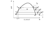
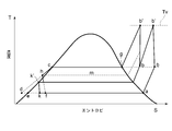
図1はT-S線図における逆エリクソンサイクルの概略図であり、図2はモリエル線図における逆エリクソンサイクルの概略図である。
図1、図2中、符号xは冷媒の飽和液線、yは冷媒の飽和蒸気線、tは等温線、Tvは単段圧縮機の吐出温度、図1中の破線pは図2中の水平線b’gに対応する等圧線、図2中の破線Sは図1中の垂直線bb’に対応する等エントロピ線を示している。理論上の逆エリクソンサイクルはabgcda(実線)で示される。理論上の逆エリクソンサイクルは2つの等温行程(d→a及びb→c)と2つの等圧行程(a→b及びc→d)からなる。2つの等圧行程abおよびcdは再生熱交換器における熱交換過程である。
図1、図2中、符号xは冷媒の飽和液線、yは冷媒の飽和蒸気線、tは等温線、Tvは単段圧縮機の吐出温度、図1中の破線pは図2中の水平線b’gに対応する等圧線、図2中の破線Sは図1中の垂直線bb’に対応する等エントロピ線を示している。理論上の逆エリクソンサイクルはabgcda(実線)で示される。理論上の逆エリクソンサイクルは2つの等温行程(d→a及びb→c)と2つの等圧行程(a→b及びc→d)からなる。2つの等圧行程abおよびcdは再生熱交換器における熱交換過程である。
部分等温行程(b→g)は理論的等温圧縮行程である。実用サイクルでは断熱圧縮行程(b→b’)と等圧放熱行程(b’→g)とに置き換える必要があり、そのため、圧縮仕事Δが余分に必要となる。等圧行程b’gはガス冷却器によって行われる。
そこで、図中実線iで示すように、前記等圧放熱行程のうち過熱蒸気領域で行われる部分行程(等温行程b→g)を、複数段の圧縮機による複数段の断熱圧縮行程と、ガス冷却器及び最終段の顕熱部分を冷却する凝縮器による複数段の等圧放熱行程とに置き換えることで、等温行程(b→g)に近似できる。
前記複数段のサイクルを構成することで、圧縮仕事Δを低減でき、COP(成績係数)の向上が可能となる。
そこで、図中実線iで示すように、前記等圧放熱行程のうち過熱蒸気領域で行われる部分行程(等温行程b→g)を、複数段の圧縮機による複数段の断熱圧縮行程と、ガス冷却器及び最終段の顕熱部分を冷却する凝縮器による複数段の等圧放熱行程とに置き換えることで、等温行程(b→g)に近似できる。
前記複数段のサイクルを構成することで、圧縮仕事Δを低減でき、COP(成績係数)の向上が可能となる。
理論サイクル上の2つの等圧行程(行程ab及び行程cd)において、ガス冷媒と液冷媒の比熱が異なるため、ガス冷媒のエンタルピー差ΔHab=Hb-Haと液冷媒のエンタルピー差ΔHcd=Hc-Hdが等しくならない。両者のエンタルピー差が等しくなる液冷媒の出口点を状態点hとするとΔHab=ΔHchの関係が満足される。この液冷媒出口点hを「顕熱限界過冷却点」と定義する。なお、再生熱交換器の液冷媒出口温度が蒸発温度と等しくなる出口点dを「湿り限界過冷却点」と定義する。液出口点dまで液冷媒を過冷却させるためには、再生熱交換器のガス側吸入点を湿り状態点a’まで移動してΔHa’b=ΔHcdの関係を満足させる必要がある。ガス側吸入点をこのように移動するには第1膨張手段(例えば膨張弁)の開度を増加させて蒸発器への給液量を増加させれば良い。
図3及び図4は、単段圧縮行程および単段膨張行程を用いた逆エリクソンサイクルの再生熱交換器と成績係数の関係を示す。両図の縦軸は成績係数(COP)を示し、横軸は再生熱交換器の液冷媒出口温度(図3)およびガス冷媒出口温度(図4)を示す。グラフ線上の○、□、△、◇等の表示記号は理論計算点の位置を表示したものであり、実験結果を示すものではない。本特性は本発明の主要部を為すものであり、以下に記号Bの冷媒R600a(イソブタン)を例にして若干詳しく説明する。
図3は再生熱交換器の液側冷媒の特性を冷媒別に示したものである。液冷媒出口温度40℃線上の点c(図1及び図2の状態点c)は過冷却度が零、換言すれば再生熱交換器を使用しない状態のCOPを示す。液冷媒出口温度-40℃線上の点d(図1及び図2の状態点d)の性能は最大過冷却温度におけるCOPを示す。図3より、再生熱交換器の液冷媒の出口温度が分れば直ちにそのときのCOPを知ることができる。
液冷媒の出口温度はガス冷媒の入口温度及び湿り度により一意に決定される。例えば、ガス冷媒入口が飽和ガス状態であれば液冷媒出口は点h(図1及び図2の状態点h)となり、COPは最大となる。そのとき液温度は図3より-13℃程度である。この状態点hは前記の「顕熱限界過冷却点」である。
液冷媒の出口温度はガス冷媒の入口温度及び湿り度により一意に決定される。例えば、ガス冷媒入口が飽和ガス状態であれば液冷媒出口は点h(図1及び図2の状態点h)となり、COPは最大となる。そのとき液温度は図3より-13℃程度である。この状態点hは前記の「顕熱限界過冷却点」である。
ガス冷媒の入口状態の湿り度を増加すると、液冷媒の過冷却温度を状態点d(-40℃)まで低下させることができる。状態点dが前記「湿り限界過冷却点」である。このときのガス冷媒の入口点(図1及び図2の状態点a’)を「湿り限界点a'」と定義する。ガス冷媒入口の湿り度を湿り限界点a'以上増加しても液冷媒出口温度は不変であり、COPは逆に低下することになる。ガス冷媒入口温度が-40℃以上の過熱温度になると、液冷媒出口状態が状態点hより高温状態となるため、図3の結果よりCOPは低下する。
図4は、再生熱交換器のガス側冷媒の特性を冷媒別に示したものである。
温度-40℃線上のCOPは再生熱交換器のガス冷媒入口が-40℃の飽和ガス状態a(図1及び図2の状態点a)であり、かつガス冷媒出口が-40℃の飽和ガス状態であるときのCOP、換言すれば、再生熱交換器を使用しない状態のCOPを示す。ガス冷媒出口温度40℃線上の点b(図1及び図2の状態点b)のCOPは、液冷媒出口温度が図1及び図2の「顕熱限界過冷却点h」となるときのCOPを示す。
図4より、再生熱交換器のガス冷媒の出口温度が分れば、直ちにそのときのCOPを知ることができる。ガス冷媒の出口温度が凝縮温度40℃から低下するほどCOPが低下する。
温度-40℃線上のCOPは再生熱交換器のガス冷媒入口が-40℃の飽和ガス状態a(図1及び図2の状態点a)であり、かつガス冷媒出口が-40℃の飽和ガス状態であるときのCOP、換言すれば、再生熱交換器を使用しない状態のCOPを示す。ガス冷媒出口温度40℃線上の点b(図1及び図2の状態点b)のCOPは、液冷媒出口温度が図1及び図2の「顕熱限界過冷却点h」となるときのCOPを示す。
図4より、再生熱交換器のガス冷媒の出口温度が分れば、直ちにそのときのCOPを知ることができる。ガス冷媒の出口温度が凝縮温度40℃から低下するほどCOPが低下する。
図3で説明したように、「顕熱限界過冷却点h」から「湿り限界過冷却点d」の区間におけるCOPは一定であることから、再生熱交換器による性能改善効果は、ガス冷媒の入口(飽和状態)と出口(過熱状態)の顕熱差を最大限利用したとき最大となることを意味する。
液冷媒の出口温度は、ガス冷媒の入口温度及び湿り度により一意的に決定されることはすでに述べた通りである。問題は、ガス冷媒の入口湿り度の影響が図4には一切示されていないことである。その理由は、ガス冷媒入口の湿り度が図1及び図2の状態aから状態a’に移動しても入口温度は一定(蒸発温度)であるため、図4の座標上に湿り度の影響を示す方法が見当たらないことによる。
このことから、再生熱交換器のガス冷媒の入口を湿り状態に維持することは理論的性能改善に無関係であるが、COPを最大化する制御法の観点から重要な意味をもつ。これについては後述する。
液冷媒の出口温度は、ガス冷媒の入口温度及び湿り度により一意的に決定されることはすでに述べた通りである。問題は、ガス冷媒の入口湿り度の影響が図4には一切示されていないことである。その理由は、ガス冷媒入口の湿り度が図1及び図2の状態aから状態a’に移動しても入口温度は一定(蒸発温度)であるため、図4の座標上に湿り度の影響を示す方法が見当たらないことによる。
このことから、再生熱交換器のガス冷媒の入口を湿り状態に維持することは理論的性能改善に無関係であるが、COPを最大化する制御法の観点から重要な意味をもつ。これについては後述する。
図3及び図4には次の二つの理論計算結果が示されている。
(1)再生熱交換器の冷端側および温端側の出入口端面における液側とガス側の冷媒温度差零℃の時の最大COP:液冷媒とガス冷媒の温度範囲はともに-40℃から40℃となり、COP最大値は図3の水平実線部分及び図4のガス冷媒出口温度40℃におけるCOPである。(図3及び図4の黒塗り点)
(2)再生熱交換器の冷端側および温端側の出入口端面における液側とガス側の冷媒温度差が5℃のときの最大COP:図3における-35℃から40℃及び図4における-40℃から35℃の温度範囲において、COP最大値は図3の水平破線部分及び図4のガス冷媒出口温度35℃におけるCOPである。(図3及び図4の白抜き点)
(1)再生熱交換器の冷端側および温端側の出入口端面における液側とガス側の冷媒温度差零℃の時の最大COP:液冷媒とガス冷媒の温度範囲はともに-40℃から40℃となり、COP最大値は図3の水平実線部分及び図4のガス冷媒出口温度40℃におけるCOPである。(図3及び図4の黒塗り点)
(2)再生熱交換器の冷端側および温端側の出入口端面における液側とガス側の冷媒温度差が5℃のときの最大COP:図3における-35℃から40℃及び図4における-40℃から35℃の温度範囲において、COP最大値は図3の水平破線部分及び図4のガス冷媒出口温度35℃におけるCOPである。(図3及び図4の白抜き点)
前記(1)と(2)の二つの計算結果を示した理由は、再生熱交換器における冷端部及び温端部の温度差(例えば5℃)による伝熱損失が発生したとき、COPがどの程度低下するかを確認するための計算値を示すためである。最大COPを示す図3の水平部分の実線部(伝熱損失零)と水平破線部(伝熱損失を考慮)を比較することにより、伝熱損失の影響を実機のCOPの変化として実感することができる。これらの計算結果を用いて正確に実機の運転条件におけるエリクソンサイクルのCOP特性を推定することが可能となる。以下にその理由を述べる。
従来冷凍サイクルの理論成績係数をCOPtc(図3の40℃における各冷媒のCOP、及び図4の-40℃における各冷媒のCOP)、逆エリクソンサイクルの理論成績係数をCOPte(前記(1)の最大COP)、再生熱交換器の損失を考慮したときの理論成績係数をCOPteh(前記(2)の破線部COP)としたとき、同一運転条件における従来冷凍サイクルの実機成績係数をCOPpc、エリクソンサイクルの実機成績係数をCOPpeとする。エリクソンサイクルの実機成績係数COPpeは従来サイクルの実機成績係数COPpcを用いて次式より予測可能である。
 ここで、式(c)のCOPlosは再生熱交換器損失によるCOP損失量を示す。
式(a)より求めたエリクソンサイクルの実機成績係数が実験値と同程度に正確である理由は、式(b)の成績係数比Rcopは理論計算値のため無誤差であり、式(c)における再生熱交換器損失を考慮したCOPteh計算値は実用的に十分な精度で計算可能であることを考慮すると、COPlosの計算精度も十分であると考えられることによる。従って、従来サイクルの実測成績係数COPpcの測定精度が十分であれば、これを用いてエリクソンサイクルの実機成績係数は式(a)より十分な精度で予測可能である。このことは、実用条件に合わせて実験確認をすることなく性能を十分な精度で予測できることを意味する。さらに、以下に示すように、再生熱交換器損失による成績係数への影響は理論成績係数の1%以下の程度であることを考慮すると、式(a)による実機性能予測値は誤差1%を超えることはあり得ず、実験結果の精度範囲にあると考えることができる。
図3及び図4に例示された冷媒のCOP損失量COPlosを計算すると、(-0.010<COPlos<0.025)程度であり、理論成績係数COPteに対する損失Rlos(=COPlos/COPteは、-0.58%(R717)<Rlos<1.1%(R600a)となる。
例えば、図3及び図4中、冷媒R600a(イソブタン)の実線成績係数(COP)は、再生熱交換器の伝熱損失が零の場合の性能を示す。液冷媒出口温度が40℃(過冷却度0℃)でCOP=1.92であり、顕熱限界過冷却点hにおける顕熱限界過冷却温度ThとCOPはTh=-13℃、COP=2.30となる。過冷却温度が-40℃となると、湿り限界過冷却点d(温度Td)における温度とCOPはそれぞれTd=-40℃、COP=2.30である。
このことは、再生熱交換器の液冷媒出口温度が限界過冷却温度Tdと顕熱限界過冷却温度Thの温度範囲内であるとき成績係数が最大かつ一定となることを示している。
このことは、再生熱交換器の液冷媒出口温度が限界過冷却温度Tdと顕熱限界過冷却温度Thの温度範囲内であるとき成績係数が最大かつ一定となることを示している。
同様に、再生熱交換器の伝熱損失を考慮して、冷端側および温端側出入り口の液冷媒とガス冷媒の温度差を5℃としたときの性能を水平破線で示す。破線部以外の性能は伝熱損失の有無に無関係に同一性能となるため一本の実線で表示されている。
図3において、液側冷媒の温度範囲は-35℃から40℃であり、図4においてガス側冷媒の温度範囲は-40℃から35℃である。再生熱交換器の冷端側温度差が5℃であることから、図4の液冷媒出口温度は-35℃であり、温端温度差が5℃であるガス冷媒出口温度は35℃である。図3より明らかなように、再生熱交換器の伝熱損失の増加に合わせて「顕熱限界過冷却点」は高温側に移動して最大COPは低下していく。
図3において、液側冷媒の温度範囲は-35℃から40℃であり、図4においてガス側冷媒の温度範囲は-40℃から35℃である。再生熱交換器の冷端側温度差が5℃であることから、図4の液冷媒出口温度は-35℃であり、温端温度差が5℃であるガス冷媒出口温度は35℃である。図3より明らかなように、再生熱交換器の伝熱損失の増加に合わせて「顕熱限界過冷却点」は高温側に移動して最大COPは低下していく。
なお、R717(NH3)の場合は、液側過冷却による冷凍能力の増加よりもガス側で圧縮機吐出温度の上昇による圧縮仕事Δの増加の影響のほうが大きいためCOPの傾向が逆になる。但し、圧縮機の段数を増加すれば各圧縮機の吐出温度を低下でき圧縮損失が改善できるので、COPを向上できる。
冷媒A(R717:アンモニア)は、単段圧縮行程および単段膨張行程を持つ逆エリクソンサイクルにおいて他の例示冷媒と著しく異なるサイクル性能を持つ。即ち、再生熱交換器による液冷媒の過冷却により性能は急速に低下する。本発明の主旨からはずれるため説明は省略するが、圧縮段数および膨張段数を増加することにより、冷媒R717といえども冷媒R600aと同程度に性能を改善させることが可能である。
幾つかの実施形態では、前記構成(1)において、
(2)前記凝縮器における冷媒の凝縮圧力をPcとし、前記蒸発器における冷媒の蒸発圧力をPeとし、前記複数段の圧縮機の段数をnとしたとき、前記複数段の断熱圧縮行程において前記複数段の圧縮機間の圧縮比rを(Pc/Pe)1/nとし、
前記制御装置は、前記ガス冷却器による前記複数段の等圧放熱行程において、入口ガス冷媒(凝縮温度+α)を凝縮温度近傍まで冷却するものである。ここでαは各段圧縮機の吸入ガスの圧縮による昇温幅であり、段数を増やすことによりαは低下させることができる。このため、圧縮機の機械的な使用温度範囲や多段化による性能改善を考慮して、αを選定するのがよい。
(2)前記凝縮器における冷媒の凝縮圧力をPcとし、前記蒸発器における冷媒の蒸発圧力をPeとし、前記複数段の圧縮機の段数をnとしたとき、前記複数段の断熱圧縮行程において前記複数段の圧縮機間の圧縮比rを(Pc/Pe)1/nとし、
前記制御装置は、前記ガス冷却器による前記複数段の等圧放熱行程において、入口ガス冷媒(凝縮温度+α)を凝縮温度近傍まで冷却するものである。ここでαは各段圧縮機の吸入ガスの圧縮による昇温幅であり、段数を増やすことによりαは低下させることができる。このため、圧縮機の機械的な使用温度範囲や多段化による性能改善を考慮して、αを選定するのがよい。
前記構成(2)によれば、前記複数段の断熱圧縮行程において、前記複数段の圧縮機間の圧縮比rを(Pc/Pe)1/nとしたことで、前記複数段の圧縮機におけるガス冷媒の吐出圧力及び吐出温度をほぼ同等にでき、一部の圧縮機で吐出圧力及び吐出温度が突出するのを抑えることができる。これによって、潤滑油の劣化やパッキン材などの焼損を抑制できる。
幾つかの実施形態では、前記構成(1)又は(2)において、
(3)前記再生熱交換器と前記第1膨張手段との間の前記冷媒循環路に設けられた第1液ガス分離器と、
前記第1液ガス分離器の入口側の前記冷媒循環路に設けられた第2膨張手段と、
前記第1液ガス分離器のガス冷媒を前記複数段の圧縮機のうちの低段側圧縮機の出口と次段の圧縮機の入口に接続された冷媒路に供給する中間ガスラインと、を有する中間冷却装置をさらに備えている。
前記構成(3)によれば、前記中間冷却装置を設けることでエンタルピ差が増加し、それに対応した全圧縮仕事の変化が起こるが、結果としてCOPが向上する。従って、冷凍又は空調装置のCOPをさらに向上できる。
(3)前記再生熱交換器と前記第1膨張手段との間の前記冷媒循環路に設けられた第1液ガス分離器と、
前記第1液ガス分離器の入口側の前記冷媒循環路に設けられた第2膨張手段と、
前記第1液ガス分離器のガス冷媒を前記複数段の圧縮機のうちの低段側圧縮機の出口と次段の圧縮機の入口に接続された冷媒路に供給する中間ガスラインと、を有する中間冷却装置をさらに備えている。
前記構成(3)によれば、前記中間冷却装置を設けることでエンタルピ差が増加し、それに対応した全圧縮仕事の変化が起こるが、結果としてCOPが向上する。従って、冷凍又は空調装置のCOPをさらに向上できる。
幾つかの実施形態では、前記構成(1)~(3)の何れかにおいて、
(4)前記再生熱交換器と前記第1膨張手段との間の前記冷媒循環路に設けられた第2液ガス分離器と、
前記第2液ガス分離器の入口側の前記冷媒循環路に設けられた第3膨張手段と、
前記第2液ガス分離器のガス冷媒を前記複数段の圧縮機のうちの低段側圧縮機の中間圧領域に供給するエコノマイザガスラインと、を有するエコノマイザ装置をさらに備えている。
前記構成(4)によれば、前記エコノマイザ装置を設けることで、エンタルピ差が増加し、それに対応した全圧縮仕事の変化が起こるが、結果としてCOPが向上する。従って、冷凍又は空調装置のCOPをさらに向上できる。
(4)前記再生熱交換器と前記第1膨張手段との間の前記冷媒循環路に設けられた第2液ガス分離器と、
前記第2液ガス分離器の入口側の前記冷媒循環路に設けられた第3膨張手段と、
前記第2液ガス分離器のガス冷媒を前記複数段の圧縮機のうちの低段側圧縮機の中間圧領域に供給するエコノマイザガスラインと、を有するエコノマイザ装置をさらに備えている。
前記構成(4)によれば、前記エコノマイザ装置を設けることで、エンタルピ差が増加し、それに対応した全圧縮仕事の変化が起こるが、結果としてCOPが向上する。従って、冷凍又は空調装置のCOPをさらに向上できる。
幾つかの実施形態では、前記構成(1)~(4)の何れかにおいて、
(5)前記複数段の圧縮機の段数が2段又は3段である。
前記複数段の圧縮機の段数が4以上になると、設備費の増加の割にCOP向上に寄与しないので、2段又は3段が実用的な段数となる。
(5)前記複数段の圧縮機の段数が2段又は3段である。
前記複数段の圧縮機の段数が4以上になると、設備費の増加の割にCOP向上に寄与しないので、2段又は3段が実用的な段数となる。
本発明の少なくとも一実施形態に係る冷凍又は空調装置の制御方法は、
(6)冷媒循環路に直列に設けられた複数段の圧縮機、凝縮器、第1膨張手段及び蒸発器と、
前記複数段の圧縮機で各圧縮機の出口と次段の圧縮機の入口と結ぶ前記冷媒循環路に設けられ、各圧縮機の吐出ガス冷媒を冷却するためのガス冷却器と、
前記蒸発器より前記圧縮機に向かうガス冷媒と前記凝縮器から前記第1膨張手段に向かう液冷媒とを熱交換させるための再生熱交換器と、を備えた冷凍又は空調装置の制御方法において、
主として前記凝縮器による等温放熱行程と、前記蒸発器による等温吸熱行程と、前記再生熱交換器における熱交換によって行われる液領域における等圧放熱行程及び過熱蒸気領域における等圧吸熱行程を含む逆エリクソンサイクルを形成すると共に、
前記等温放熱行程のうち過熱蒸気領域で行われる部分行程が、前記複数段の圧縮機による複数段の断熱圧縮行程と、前記ガス冷却器及び前記凝縮器による複数段の等圧放熱行程とに置き換えた第1行程と、
前記等圧吸熱行程で湿り状態の冷媒を前記再生熱交換器に導入し、前記等圧吸熱行程で飽和ガス冷媒が前記再生熱交換器に導入されたときの前記等温放熱行程の終了点となる顕熱限界過冷却点から、前記第1膨張手段による断熱膨張行程の終了点が飽和冷媒液線上に位置するときの前記等温放熱行程の終了点となる湿り限界過冷却点までの領域の過冷却点に前記等温放熱行程の終了点が位置するように制御する第2行程と、を含んでいる。
(6)冷媒循環路に直列に設けられた複数段の圧縮機、凝縮器、第1膨張手段及び蒸発器と、
前記複数段の圧縮機で各圧縮機の出口と次段の圧縮機の入口と結ぶ前記冷媒循環路に設けられ、各圧縮機の吐出ガス冷媒を冷却するためのガス冷却器と、
前記蒸発器より前記圧縮機に向かうガス冷媒と前記凝縮器から前記第1膨張手段に向かう液冷媒とを熱交換させるための再生熱交換器と、を備えた冷凍又は空調装置の制御方法において、
主として前記凝縮器による等温放熱行程と、前記蒸発器による等温吸熱行程と、前記再生熱交換器における熱交換によって行われる液領域における等圧放熱行程及び過熱蒸気領域における等圧吸熱行程を含む逆エリクソンサイクルを形成すると共に、
前記等温放熱行程のうち過熱蒸気領域で行われる部分行程が、前記複数段の圧縮機による複数段の断熱圧縮行程と、前記ガス冷却器及び前記凝縮器による複数段の等圧放熱行程とに置き換えた第1行程と、
前記等圧吸熱行程で湿り状態の冷媒を前記再生熱交換器に導入し、前記等圧吸熱行程で飽和ガス冷媒が前記再生熱交換器に導入されたときの前記等温放熱行程の終了点となる顕熱限界過冷却点から、前記第1膨張手段による断熱膨張行程の終了点が飽和冷媒液線上に位置するときの前記等温放熱行程の終了点となる湿り限界過冷却点までの領域の過冷却点に前記等温放熱行程の終了点が位置するように制御する第2行程と、を含んでいる。
前記構成(6)によれば、前記第1行程により、実用サイクルを理論上の逆エリクソンサイクルに近づけることができるので、COPを向上できると共に、ガス冷媒の温度上昇を抑制できるため、冷媒に含まれる潤滑油の劣化を防止できると共に、パッキン材などを構成するエラストマの焼損を防止できる。
さらに、前記第2行程により、冷凍又は空調装置のCOPを最大に維持できると共に、最適制御条件が点設定でなく範囲設定となるため制御が極めて容易である。
さらに、前記第2行程により、冷凍又は空調装置のCOPを最大に維持できると共に、最適制御条件が点設定でなく範囲設定となるため制御が極めて容易である。
幾つかの実施形態では、前記構成(6)において、
(7)前記第2行程は、少なくとも前記複数段の圧縮機を駆動するモータの回転数制御と、前記第1膨張手段の制御とで行われる。
前記構成(7)によれば、従来から行われている簡単な制御でCOPを向上できる。
(7)前記第2行程は、少なくとも前記複数段の圧縮機を駆動するモータの回転数制御と、前記第1膨張手段の制御とで行われる。
前記構成(7)によれば、従来から行われている簡単な制御でCOPを向上できる。
(8)幾つかの実施形態では、前記構成(6)又は(7)において、
前記第2行程は、
前記凝縮器から前記第1膨張手段に向かう液冷媒の前記再生熱交換器出口における温度を検出する第1ステップと、
前記第1ステップで検出した温度検出値を、前記顕熱限界過冷却点における冷媒温度から前記蒸発器における冷媒の蒸発温度までの間の温度に制御する第2ステップと、を含んでいる。
前記構成(8)によれば、前記温度検出値は蒸発器や再生熱交換器に設けた温度センサの検出値から、顕熱限界過冷却点や湿り限界過冷却点を容易に求めることができる。
前記第2行程は、
前記凝縮器から前記第1膨張手段に向かう液冷媒の前記再生熱交換器出口における温度を検出する第1ステップと、
前記第1ステップで検出した温度検出値を、前記顕熱限界過冷却点における冷媒温度から前記蒸発器における冷媒の蒸発温度までの間の温度に制御する第2ステップと、を含んでいる。
前記構成(8)によれば、前記温度検出値は蒸発器や再生熱交換器に設けた温度センサの検出値から、顕熱限界過冷却点や湿り限界過冷却点を容易に求めることができる。
本発明の少なくとも一実施形態によれば、近似逆エリクソンサイクルを用いた冷凍又は空調装置において、熱効率のさらなる向上が可能になる。
以下、添付図面を参照して本発明の幾つかの実施形態について説明する。ただし、実施形態として記載され又は図面に示されている構成部品の寸法、材質、形状、その相対的配置等は、本発明の範囲をこれに限定する趣旨ではなく、単なる説明例にすぎない。
例えば、「ある方向に」、「ある方向に沿って」、「平行」、「直交」、「中心」、「同心」或いは「同軸」等の相対的或いは絶対的な配置を表す表現は、厳密にそのような配置を表すのみならず、公差、若しくは、同じ機能が得られる程度の角度や距離をもって相対的に変位している状態も表すものとする。
例えば、「同一」、「等しい」及び「均質」等の物事が等しい状態であることを表す表現は、厳密に等しい状態を表すのみならず、公差、若しくは、同じ機能が得られる程度の差が存在している状態も表すものとする。
例えば、四角形状や円筒形状等の形状を表す表現は、幾何学的に厳密な意味での四角形状や円筒形状等の形状を表すのみならず、同じ効果が得られる範囲で、凹凸部や面取り部等を含む形状も表すものとする。
一方、一つの構成要素を「備える」、「具える」、「具備する」、「含む」、又は「有する」という表現は、他の構成要素の存在を除外する排他的な表現ではない。
例えば、「ある方向に」、「ある方向に沿って」、「平行」、「直交」、「中心」、「同心」或いは「同軸」等の相対的或いは絶対的な配置を表す表現は、厳密にそのような配置を表すのみならず、公差、若しくは、同じ機能が得られる程度の角度や距離をもって相対的に変位している状態も表すものとする。
例えば、「同一」、「等しい」及び「均質」等の物事が等しい状態であることを表す表現は、厳密に等しい状態を表すのみならず、公差、若しくは、同じ機能が得られる程度の差が存在している状態も表すものとする。
例えば、四角形状や円筒形状等の形状を表す表現は、幾何学的に厳密な意味での四角形状や円筒形状等の形状を表すのみならず、同じ効果が得られる範囲で、凹凸部や面取り部等を含む形状も表すものとする。
一方、一つの構成要素を「備える」、「具える」、「具備する」、「含む」、又は「有する」という表現は、他の構成要素の存在を除外する排他的な表現ではない。
(実施形態1)
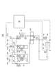
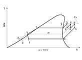
図5~図12は、本発明に係る冷凍又は空調装置の幾つかの実施形態を示している。このうち、図5は3段圧縮3段膨張を行う冷凍装置10Aを示し、図6は冷凍装置10Aが構成する近似逆エリクソンサイクルのT-S線図である。
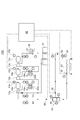
図7は3段圧縮2段膨張を行う冷凍装置10Bを示し、図8は冷凍装置10Bが構成する近似逆エリクソンサイクルのT-S線図であり、図9は該近似逆エリクソンサイクルのモリエル線図である。
図10は3段圧縮単段膨張を行う冷凍装置10Cを示し、図11は冷凍装置10Cが構成する近似逆エリクソンサイクルのT-S線図である。
図12は3段圧縮2段膨張を行う冷凍装置10Dを示している。
図5~図12は、本発明に係る冷凍又は空調装置の幾つかの実施形態を示している。このうち、図5は3段圧縮3段膨張を行う冷凍装置10Aを示し、図6は冷凍装置10Aが構成する近似逆エリクソンサイクルのT-S線図である。
図7は3段圧縮2段膨張を行う冷凍装置10Bを示し、図8は冷凍装置10Bが構成する近似逆エリクソンサイクルのT-S線図であり、図9は該近似逆エリクソンサイクルのモリエル線図である。
図10は3段圧縮単段膨張を行う冷凍装置10Cを示し、図11は冷凍装置10Cが構成する近似逆エリクソンサイクルのT-S線図である。
図12は3段圧縮2段膨張を行う冷凍装置10Dを示している。
図5~図12に示す冷凍装置10A~10Dは、冷媒循環路12に冷凍サイクルを構成する複数段(3段)の圧縮機13a、13b及び13c、凝縮器16、第1膨張弁18及び蒸発器20が直列に設けられている。各圧縮機は夫々電動モータ14a、14b及び14cによって回転駆動される。前記圧縮機は、例えばスクリュー圧縮機などの容積型圧縮機が用いられる。但し、運転条件の変動が少ない用途にターボ式圧縮機が使われることもある。
各圧縮機の出口と入口とを接続するガス冷媒路12a及び12bに、冷却水などの冷却媒体で圧縮機13a又は13bから吐出されたガス冷媒を冷却するガス冷却器22a及び22bを備えている。
さらに、蒸発器20より圧縮機13aに向かうガス冷媒と凝縮器16から出た液冷媒とを熱交換させるための再生熱交換器24を備えている。
各圧縮機の出口と入口とを接続するガス冷媒路12a及び12bに、冷却水などの冷却媒体で圧縮機13a又は13bから吐出されたガス冷媒を冷却するガス冷却器22a及び22bを備えている。
さらに、蒸発器20より圧縮機13aに向かうガス冷媒と凝縮器16から出た液冷媒とを熱交換させるための再生熱交換器24を備えている。
冷凍装置10A及び10Bの例示的な構成として、再生熱交換器24と第1膨張弁18との間の冷媒循環路12に設けられた第1液ガス分離器28と、第1液ガス分離器28の入口側の冷媒循環路12に設けられた第2膨張弁30と、第1液ガス分離器28で液冷媒と分離されたガス冷媒を第1段圧縮機13aの出口と第2段圧縮機13bの入口とに接続された冷媒路12aに供給する中間ガス路32とを有する中間冷却装置26をさらに備えている。中間ガス路32はガス冷却器22aの下流側で冷媒路12aに接続されている。
冷凍装置10A及び10Dの例示的な構成として、再生熱交換器24と第1膨張弁18との間の冷媒循環路12に設けられた第2液ガス分離器36と、第2液ガス分離器36の入口側の冷媒循環路12に設けられた第3膨張弁38と、第2液ガス分離器36のガス冷媒を第1段圧縮機13aの中間圧領域に供給するエコノマイザガス路40とを有するエコノマイザ装置34をさらに備えている。
なお、冷凍装置10Aでは、第1液ガス分離器28の液冷媒を冷媒循環路12を通して第2液ガス分離器36に供給し、冷凍装置10Bでは再生熱交換器24から冷媒循環路12を介して第1液ガス分離器28に液冷媒を供給している。
なお、冷凍装置10Aでは、第1液ガス分離器28の液冷媒を冷媒循環路12を通して第2液ガス分離器36に供給し、冷凍装置10Bでは再生熱交換器24から冷媒循環路12を介して第1液ガス分離器28に液冷媒を供給している。
図中、符号Pは圧力センサの配置を示し、Tは温度センサの配置を示し、Gは冷媒液面のレベルセンサの配置を示している。冷凍装置10A~10Dの各所に設けられた前記温度センサ、前記圧力センサ及び前記レベルセンサ、駆動モータ14a、14b及び14cに設けられた回転数センサ44a、44b及び44c等の検出値はすべて制御装置42に入力される。
制御装置42は、これらの検出値に基づいて、第1膨張弁18、第2膨張弁30及び第3膨張弁38の開度、及び電動モータ14a、14b及び14cの回転数、中間ガスライン32に設けられた流量調整弁46の開度及びエコノマイザガス路40に設けられた流量調整弁48の開度等を制御する。
制御装置42は、これらの検出値に基づいて、第1膨張弁18、第2膨張弁30及び第3膨張弁38の開度、及び電動モータ14a、14b及び14cの回転数、中間ガスライン32に設けられた流量調整弁46の開度及びエコノマイザガス路40に設けられた流量調整弁48の開度等を制御する。
かかる構成において、冷凍装置10A~10Dは理論上の逆エリクソンサイクルに近似した前述の実用的逆エリクソンサイクルを構成する。冷凍装置10A~10Dが構成する近似逆エリクソンサイクルは、図6、図8及び図11のT-S線図、及び図9のモリエル線図に示される。
冷凍装置10A~10Dの近似逆エリクソンサイクルは、主として凝縮器16による等温放熱行程(b→c)と、蒸発器20による等温吸熱行程(f→a)と、再生熱交換器24によって行われる液領域の等圧放熱行程(c→h)及び過熱蒸気領域の等圧吸熱行程(a→b)を含んでいる。
また、等温放熱行程(b→c)のうち過熱蒸気領域で行われる部分行程が、複数段の圧縮機13a、13b及び13cによる複数段の断熱圧縮行程(b→b’)と、ガス冷却器22a及び22b及び凝縮器16による複数段の等圧放熱行程(b’→b)及び凝縮器16による1段の等圧放熱行程(b’→g)とに置き換えられる(第1行程)。
冷凍装置10A~10Dの近似逆エリクソンサイクルは、主として凝縮器16による等温放熱行程(b→c)と、蒸発器20による等温吸熱行程(f→a)と、再生熱交換器24によって行われる液領域の等圧放熱行程(c→h)及び過熱蒸気領域の等圧吸熱行程(a→b)を含んでいる。
また、等温放熱行程(b→c)のうち過熱蒸気領域で行われる部分行程が、複数段の圧縮機13a、13b及び13cによる複数段の断熱圧縮行程(b→b’)と、ガス冷却器22a及び22b及び凝縮器16による複数段の等圧放熱行程(b’→b)及び凝縮器16による1段の等圧放熱行程(b’→g)とに置き換えられる(第1行程)。
冷凍装置10A~10Dの例示的な構成では、凝縮器16における凝縮圧力をPc、蒸発器20における蒸発圧力をPe、複数段の圧縮機の段数をnとしたとき、各圧縮機間の圧縮比を(Pc/Pe)1/nとする。冷凍装置10A~10Dは3段の圧縮機13a、13b及び13cを有するので、各圧縮機間の圧縮比は(Pc/Pe)1/3となる。
また、ガス冷却器22a及び22bによる2段の等圧放熱行程において、吐出ガス冷媒温度を(凝縮温度+α)として、各段の等圧放熱工程でα分を冷却することで、一部の圧縮機での吐出温度の突出を抑制して均質な圧縮と放熱を実現する。
また、ガス冷却器22a及び22bによる2段の等圧放熱行程において、吐出ガス冷媒温度を(凝縮温度+α)として、各段の等圧放熱工程でα分を冷却することで、一部の圧縮機での吐出温度の突出を抑制して均質な圧縮と放熱を実現する。
制御装置42は、再生熱交換器24の液側出口温度Tloutが過冷却液出口温度の設定値Tsetとなるように、蒸発器20の入口に直結された第1膨張弁18の開度を制御する。このときの蒸発器出口の湿り度は状態点(a’~a)の湿り度となるように制御される。再生熱交換器24のガス側入口状態が状態点(a’~a)であるとき再生熱交換器液側出口温度Tloutは顕熱限界過冷却点hと湿り限界過冷却点dの温度範囲内に設定された設定温度Tsetと等しくなる。
制御装置42による例示的な制御方法として、前記第2行程は、電動モータ14a、14b及び14cの回転数制御と第1膨張弁18の開度制御とを併用すればよい。
再生熱交換器24の出口の液冷媒路12cに温度センサ50が設けられ、蒸発器20の出口の冷媒路12に圧力センサ52及び温度センサ54が設けられている。
制御装置42による例示的な制御方法は、まず、凝縮器16から第1膨張弁18に向かう液冷媒の再生熱交換器24の出口における温度を検出する(第1ステップ)。
次に、検出した温度を顕熱限界過冷却点hの冷媒温度Thから温度センサ54で検出した蒸発器20における冷媒の蒸発温度までの間の温度に制御する(第2ステップ)。
再生熱交換器24の出口の液冷媒路12cに温度センサ50が設けられ、蒸発器20の出口の冷媒路12に圧力センサ52及び温度センサ54が設けられている。
制御装置42による例示的な制御方法は、まず、凝縮器16から第1膨張弁18に向かう液冷媒の再生熱交換器24の出口における温度を検出する(第1ステップ)。
次に、検出した温度を顕熱限界過冷却点hの冷媒温度Thから温度センサ54で検出した蒸発器20における冷媒の蒸発温度までの間の温度に制御する(第2ステップ)。
図6及び図8、9において、1段圧縮機13a及び2段圧縮機13bの吐出ガス冷媒(凝縮温度+α)はガス冷却器22a及び22bにより凝縮温度近傍まで冷却される。3段圧縮機13cの吐出ガス冷媒は凝縮器16に送られる。
液ガス分離器28の冷媒温度は膨張弁入口温度Thから膨張弁出口温度Tk’まで低下し、第1膨張弁18を経て蒸発温度Teとなり、蒸発器20に供給される。この多段の圧縮・膨張法によりΔHkfのエンタルピが増加分に対応した全圧縮仕事の変化が起こるが、結果としてCOPが向上する。
図6の近似逆エリクソンサイクルでは、エコノマイザ装置34のガス冷媒を1段圧縮機13aのエコノマイザポートに吸入させることで、第3膨張弁入口温度Tk’から膨張弁出口温度Tl’に低下させ、さらにΔHlkのエンタルピが増加し、結果としてCOPを向上できる。
液ガス分離器28の冷媒温度は膨張弁入口温度Thから膨張弁出口温度Tk’まで低下し、第1膨張弁18を経て蒸発温度Teとなり、蒸発器20に供給される。この多段の圧縮・膨張法によりΔHkfのエンタルピが増加分に対応した全圧縮仕事の変化が起こるが、結果としてCOPが向上する。
図6の近似逆エリクソンサイクルでは、エコノマイザ装置34のガス冷媒を1段圧縮機13aのエコノマイザポートに吸入させることで、第3膨張弁入口温度Tk’から膨張弁出口温度Tl’に低下させ、さらにΔHlkのエンタルピが増加し、結果としてCOPを向上できる。
なお、顕熱限界過冷却点hの冷媒温度Thは例えば-10℃前後になるため、膨張弁出口に付設された中間ガス路32及びエコノマイザガス路40は、顕熱限界過冷却点hのガス冷媒圧力より低い低段側圧縮機に接続する必要がある。即ち、図6、図8及び図11等で破線mより低圧の領域である。
また、圧縮機の段数を増加するほど吐出温度Tvが低下し、圧縮機の動力を低減できるが、圧縮機段数を増加するほど設備費が増加するので、2段又は3段が適当である。
また、圧縮機の段数を増加するほど吐出温度Tvが低下し、圧縮機の動力を低減できるが、圧縮機段数を増加するほど設備費が増加するので、2段又は3段が適当である。
冷凍装置10A~10Dによれば、過熱蒸気領域で行われる部分行程(等温行程b→g)を、複数段の圧縮機13a、13b及び13cによる複数段の断熱圧縮行程と、ガス冷却器22a、22b及び凝縮器16による複数段の等圧放熱行程とに置き換えることで、圧縮仕事Δを低減でき、COPを向上できる。
また、制御装置42により、蒸発器20から湿り状態の冷媒を再生熱交換器24のガス側入口に導入し、該再生熱交換器の液側出口における等温放熱行程の終了点が顕熱限界過冷却点hから湿り限界過冷却点dまでの領域の過冷却点に位置するように制御することで、冷凍装置10A~10DのCOPを最大に維持できる。また、顕熱限界過冷却点hと湿り限界過冷却点dとの間の広い範囲で制御すればよいので、制御が容易になる。
また、制御装置42により、蒸発器20から湿り状態の冷媒を再生熱交換器24のガス側入口に導入し、該再生熱交換器の液側出口における等温放熱行程の終了点が顕熱限界過冷却点hから湿り限界過冷却点dまでの領域の過冷却点に位置するように制御することで、冷凍装置10A~10DのCOPを最大に維持できる。また、顕熱限界過冷却点hと湿り限界過冷却点dとの間の広い範囲で制御すればよいので、制御が容易になる。
また、前記複数段の等圧放熱行程では、(凝縮温度+α)の吐出ガス冷媒を凝縮温度近傍まで冷却することで、一部の圧縮機での吐出温度の突出を抑制して均質な圧縮と放熱を実現する。
また、過熱蒸気領域における複数段の等圧放熱行程(b’→b)及び(b’→g)によりガス冷媒の温度を低下できるため、冷媒に含まれる潤滑油の劣化及びパッキン材などを構成するエラストマの焼損を防止できる。例えば、凝縮温度40℃、蒸発温度-40℃で圧縮機の吸入ガス冷媒温度が40℃の条件で、比熱比の高い冷媒のR717(NH3)の場合は、単段圧縮では約380℃、2段圧縮で約180℃、3段圧縮では約120℃程度となり、昇温幅αは単段で340℃、2段圧縮機で140℃、3段圧縮機で80℃となり、段数が増えることにより冷媒ガス温度の降下が期待できる。
特に、前記複数段の断熱圧縮行程において3段圧縮の場合、圧縮機間の圧縮比を(凝縮圧力Pc/蒸発圧力Pe)1/3としたことで、各圧縮機のガス冷媒の吐出温度をほぼ同等に制御できるため、一部の圧縮機での吐出温度の突出を抑制できる。
また、過熱蒸気領域における複数段の等圧放熱行程(b’→b)及び(b’→g)によりガス冷媒の温度を低下できるため、冷媒に含まれる潤滑油の劣化及びパッキン材などを構成するエラストマの焼損を防止できる。例えば、凝縮温度40℃、蒸発温度-40℃で圧縮機の吸入ガス冷媒温度が40℃の条件で、比熱比の高い冷媒のR717(NH3)の場合は、単段圧縮では約380℃、2段圧縮で約180℃、3段圧縮では約120℃程度となり、昇温幅αは単段で340℃、2段圧縮機で140℃、3段圧縮機で80℃となり、段数が増えることにより冷媒ガス温度の降下が期待できる。
特に、前記複数段の断熱圧縮行程において3段圧縮の場合、圧縮機間の圧縮比を(凝縮圧力Pc/蒸発圧力Pe)1/3としたことで、各圧縮機のガス冷媒の吐出温度をほぼ同等に制御できるため、一部の圧縮機での吐出温度の突出を抑制できる。
また、幾つかの実施形態によれば、中間冷却装置26又はエコノマイザ装置34を設けたことで、圧縮機から吐出するガス冷媒の吐出圧力及び吐出温度を低減でき、これによって、圧縮機動力を低減でき、冷凍装置のCOPをさらに向上できる。
また、制御装置42による前記制御は、複数段の圧縮機13a、13b及び13cを駆動する電動モータ14a、14b及び14cの回転数制御と、第1膨張弁18の開度制御とで行う簡易な制御で容易に行うことができる。
さらに、顕熱限界過冷却点hや湿り限界過冷却点dの検出は、蒸発器20の出口や再生熱交換器24の出口に設けられた温度センサ50、54及び圧力センサ52の検出値から容易に求めることができる。
また、制御装置42による前記制御は、複数段の圧縮機13a、13b及び13cを駆動する電動モータ14a、14b及び14cの回転数制御と、第1膨張弁18の開度制御とで行う簡易な制御で容易に行うことができる。
さらに、顕熱限界過冷却点hや湿り限界過冷却点dの検出は、蒸発器20の出口や再生熱交換器24の出口に設けられた温度センサ50、54及び圧力センサ52の検出値から容易に求めることができる。
図13は、他の実施形態として2段圧縮2段膨張を行う冷凍装置10Eを示し、図14は冷凍装置10Eが構成する近似逆エリクソンサイクルを示している。
前述のように、複数段の圧縮機の段数を2段又は3段とすることで、設備費の増加を抑えつつCOPを向上できる。
前述のように、複数段の圧縮機の段数を2段又は3段とすることで、設備費の増加を抑えつつCOPを向上できる。
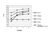
図15は近似逆エリクソンサイクル及び従来冷凍サイクルのCOPを示す線図である。図15は中間冷却装置やエコノマイザ装置を付設しない場合を示す。本発明の各実施形態で得られるCOPは従来の冷凍サイクルより向上していることがわかる。
図15において、冷媒がR717(NH3)で2段圧縮の場合、従来冷凍サイクルよりCOPが下回っているが、圧縮段数を増加するに従い、各圧縮機からのガス冷媒の吐出温度が低下し、圧縮機動力を低減できる。そのため、圧縮損失を改善でき、従来冷凍サイクルよりCOPを向上できる。
また、図15から、圧縮機の段数が4段以上となってもCOPの増加はあまり見込めないことがわかる。
図15において、冷媒がR717(NH3)で2段圧縮の場合、従来冷凍サイクルよりCOPが下回っているが、圧縮段数を増加するに従い、各圧縮機からのガス冷媒の吐出温度が低下し、圧縮機動力を低減できる。そのため、圧縮損失を改善でき、従来冷凍サイクルよりCOPを向上できる。
また、図15から、圧縮機の段数が4段以上となってもCOPの増加はあまり見込めないことがわかる。
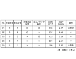
図16は、図5~図12に示す前記幾つかの実施形態に係る冷凍装置のCOP(計算値)を示す図表である。そのうち、図16比較例No.05および本発明No.04は図15に示す単段圧縮、3段圧縮の近似逆エリクソンサイクルのCOPと同じ値である。
本発明では、中間冷却装置やエコノマイザ装置をさらに備えて顕熱限界過冷却点hを下回る冷媒液を、膨張弁を用いて冷媒温度ThからTk’またはTl’に低下させることにより、ΔHkf(=ΔHf-ΔHk)、又はΔHlf (=ΔHf-ΔHl)のエンタルピ差が増加し結果としてCOPが向上することになり、図16No.1~No.3の組合せによって更なる性能改善効果が期待できる。
本発明では、中間冷却装置やエコノマイザ装置をさらに備えて顕熱限界過冷却点hを下回る冷媒液を、膨張弁を用いて冷媒温度ThからTk’またはTl’に低下させることにより、ΔHkf(=ΔHf-ΔHk)、又はΔHlf (=ΔHf-ΔHl)のエンタルピ差が増加し結果としてCOPが向上することになり、図16No.1~No.3の組合せによって更なる性能改善効果が期待できる。
本発明の少なくとも一実施形態によれば、近似逆エリクソンサイクルを用いた冷凍又は空調装置において、熱効率のさらなる向上が可能になる。
10A、10B、10C、10D、10E 冷凍装置
12 冷媒循環路
12a、12b ガス冷媒路
13a、13b、13c 圧縮機
14a、14b、14c 電動モータ
16 凝縮器
18 第1膨張弁
20 蒸発器
22a、22b ガス冷却器
24 再生熱交換器
26 中間冷却装置
28、36 液ガス分離器
30 第2膨張弁
32 中間ガス路
34 エコノマイザ装置
38 第3膨張弁
40 エコノマイザガス路
42 制御装置
44a、44b、44c 回転数センサ
46、48 流量調整弁
50、54 温度センサ
52 圧力センサ
Tv 圧縮機吐出温度
d 湿り限界過冷却点
h 顕熱限界過冷却点
p 等圧線
t 等温線
x 飽和液線
y 飽和蒸気線
Δ 圧縮仕事
12 冷媒循環路
12a、12b ガス冷媒路
13a、13b、13c 圧縮機
14a、14b、14c 電動モータ
16 凝縮器
18 第1膨張弁
20 蒸発器
22a、22b ガス冷却器
24 再生熱交換器
26 中間冷却装置
28、36 液ガス分離器
30 第2膨張弁
32 中間ガス路
34 エコノマイザ装置
38 第3膨張弁
40 エコノマイザガス路
42 制御装置
44a、44b、44c 回転数センサ
46、48 流量調整弁
50、54 温度センサ
52 圧力センサ
Tv 圧縮機吐出温度
d 湿り限界過冷却点
h 顕熱限界過冷却点
p 等圧線
t 等温線
x 飽和液線
y 飽和蒸気線
Δ 圧縮仕事
Claims (8)
- 冷媒循環路に直列に設けられた複数段の圧縮機、凝縮器、第1膨張手段及び蒸発器と、
前記複数段の圧縮機で各圧縮機の出口と次段の圧縮機の入口とを結ぶ前記冷媒循環路に設けられ、各圧縮機の吐出ガス冷媒を冷却するためのガス冷却器と、
前記蒸発器より前記圧縮機に向かうガス冷媒と前記凝縮器から前記第1膨張手段に向かう液冷媒とを熱交換させるための再生熱交換器と、を備え、
主として前記凝縮器による等温放熱行程と、前記蒸発器による等温吸熱行程と、前記再生熱交換器における熱交換によって行われる液領域における等圧放熱行程及び過熱蒸気領域における等圧吸熱行程とを含む逆エリクソンサイクルを形成すると共に、
前記等温放熱行程のうち過熱蒸気領域で行われる部分行程が、前記複数段の圧縮機による複数段の断熱圧縮行程と、前記ガス冷却器及び前記凝縮器による複数段の等圧放熱行程とに置き換えられ、
前記等圧吸熱行程で湿り状態の冷媒を前記再生熱交換器に導入し、前記等圧吸熱行程で飽和ガス冷媒が前記再生熱交換器に導入されたときの前記等圧放熱行程の終了点となる顕熱限界過冷却点から、前記第1膨張手段による断熱膨張行程の終了点が飽和冷媒液線上に位置するときの前記等圧放熱行程の終了点となる湿り限界過冷却点までの過冷却点に前記等圧放熱行程の終了点が位置するように制御するための制御装置をさらに備えていることを特徴とする冷凍又は空調装置。 - 前記凝縮器における冷媒の凝縮圧力をPcとし、前記蒸発器における冷媒の蒸発圧力をPeとし、前記複数段の圧縮機の段数をnとしたとき、前記複数段の断熱圧縮行程において前記複数段の圧縮機間の圧縮比rを(Pc/Pe)1/nとし、
前記制御装置は、前記ガス冷却器による前記複数段の等圧放熱行程において、各段の吐出ガス冷媒(凝縮温度+α)を凝縮温度近傍まで冷却するものであることを特徴とする請求項1に記載の冷凍又は空調装置。 - 前記再生熱交換器と前記第1膨張手段との間の前記冷媒循環路に設けられた第1液ガス分離器と、
前記第1液ガス分離器の入口側の前記冷媒循環路に設けられた第2膨張手段と、
前記第1液ガス分離器のガス冷媒を前記複数段の圧縮機のうちの低段側圧縮機の出口と次段の圧縮機の入口に接続された冷媒路に供給する中間ガス路と、を有する中間冷却装置をさらに備えていることを特徴とする請求項1又は2に記載の冷凍又は空調装置。 - 前記再生熱交換器と前記第1膨張手段との間の前記冷媒循環路に設けられた第2液ガス分離器と、
前記第2液ガス分離器の入口側の前記冷媒循環路に設けられた第3膨張手段と、
前記第2液ガス分離器のガス冷媒を前記複数段の圧縮機のうちの低段側圧縮機の中間圧領域に供給するエコノマイザガス路と、を有するエコノマイザ装置をさらに備えていることを特徴とする請求項1乃至3の何れか1項に記載の冷凍又は空調装置。 - 前記複数段の圧縮機の段数が2段又は3段であることを特徴とする請求項1乃至4の何れか1項に記載の冷凍又は空調装置。
- 冷媒循環路に直列に設けられた複数段の圧縮機、凝縮器、第1膨張手段及び蒸発器と、
前記複数段の圧縮機で各圧縮機の出口と次段の圧縮機の入口と結ぶ前記冷媒循環路に設けられ、各圧縮機の吐出ガス冷媒を冷却するためのガス冷却器と、
前記蒸発器より前記圧縮機に向かうガス冷媒と前記凝縮器から前記第1膨張手段に向かう液冷媒とを熱交換させるための再生熱交換器と、を備えた冷凍又は空調装置の制御方法において、
主として前記凝縮器による等温放熱行程と、前記蒸発器による等温吸熱行程と、前記再生熱交換器における熱交換によって行われる液領域における等圧放熱行程及び過熱蒸気領域における等圧吸熱行程を含む逆エリクソンサイクルを形成すると共に、
前記等温放熱行程のうち過熱蒸気領域で行われる部分行程が、前記複数段の圧縮機による複数段の断熱圧縮行程と、前記ガス冷却器及び前記凝縮器による複数段の等圧放熱行程とに置き換えた第1行程と、
前記等圧吸熱行程で湿り状態の冷媒を前記再生熱交換器に導入し、前記等圧吸熱行程で飽和ガス冷媒が前記再生熱交換器に導入されたときの前記等温放熱行程の終了点となる顕熱限界過冷却点から、前記第1膨張手段による断熱膨張行程の終了点が飽和冷媒液線上に位置するときの前記等温放熱行程の終了点となる湿り限界過冷却点までの領域の過冷却点に前記等温放熱行程の終了点が位置するように制御する第2行程と、を含むことを特徴とする冷凍又は空調装置の制御方法。 - 前記第2行程は、少なくとも前記複数段の圧縮機を駆動するモータの回転数制御と、前記第1膨張手段の制御とで行われることを特徴とする請求項6に記載の冷凍又は空調装置の制御方法。
- 前記第2行程は、
前記凝縮器から前記第1膨張手段に向かう液冷媒の前記再生熱交換器出口における温度を検出する第1ステップと、
前記第1ステップで検出した温度検出値を、前記顕熱限界過冷却点における冷媒温度から前記蒸発器における冷媒の蒸発温度までの間の温度に制御する第2ステップと、を含むことを特徴とする請求項6又は7に記載の冷凍又は空調装置の制御方法。
Applications Claiming Priority (2)
| Application Number | Priority Date | Filing Date | Title |
|---|---|---|---|
| JP2014266465A JP6456139B2 (ja) | 2014-12-26 | 2014-12-26 | 冷凍又は空調装置及びその制御方法 |
| JP2014-266465 | 2014-12-26 |
Publications (1)
| Publication Number | Publication Date |
|---|---|
| WO2016104147A1 true WO2016104147A1 (ja) | 2016-06-30 |
Family
ID=56150177
Family Applications (1)
| Application Number | Title | Priority Date | Filing Date |
|---|---|---|---|
| PCT/JP2015/084522 Ceased WO2016104147A1 (ja) | 2014-12-26 | 2015-12-09 | 冷凍又は空調装置及びその制御方法 |
Country Status (2)
| Country | Link |
|---|---|
| JP (1) | JP6456139B2 (ja) |
| WO (1) | WO2016104147A1 (ja) |
Cited By (1)
| Publication number | Priority date | Publication date | Assignee | Title |
|---|---|---|---|---|
| JP2019074250A (ja) * | 2017-10-16 | 2019-05-16 | 株式会社デンソー | ヒートポンプサイクル |
Families Citing this family (3)
| Publication number | Priority date | Publication date | Assignee | Title |
|---|---|---|---|---|
| WO2021152844A1 (ja) * | 2020-01-31 | 2021-08-05 | 三菱電機株式会社 | 室外ユニットおよび冷凍サイクル装置 |
| FR3118484B1 (fr) * | 2020-12-28 | 2025-04-18 | Commissariat A L’Energie Atomique Et Aux Energies Alternatives | Système de compression à plusieurs étages de compression montés en série |
| JPWO2024189697A1 (ja) * | 2023-03-10 | 2024-09-19 |
Citations (5)
| Publication number | Priority date | Publication date | Assignee | Title |
|---|---|---|---|---|
| JPS5556567A (en) * | 1978-10-20 | 1980-04-25 | Takatama Mitsuko | Method of refrigeration by vapor compression |
| JP2004061061A (ja) * | 2002-07-31 | 2004-02-26 | Matsushita Electric Ind Co Ltd | 冷凍サイクル装置およびその運転方法 |
| JP2008185327A (ja) * | 2007-01-26 | 2008-08-14 | Grasso Gmbh Refrigeration Technology | 二段配置形式のオイルオーバフロー式スクリューコンプレッサを備えたco2冷凍装置 |
| JP2009133547A (ja) * | 2007-11-30 | 2009-06-18 | Mitsubishi Electric Corp | 冷凍サイクル装置 |
| JP2009529123A (ja) * | 2006-03-27 | 2009-08-13 | 株式会社前川製作所 | 蒸気圧縮式冷凍サイクル、その制御方法およびそれを用いた冷凍装置 |
-
2014
- 2014-12-26 JP JP2014266465A patent/JP6456139B2/ja active Active
-
2015
- 2015-12-09 WO PCT/JP2015/084522 patent/WO2016104147A1/ja not_active Ceased
Patent Citations (5)
| Publication number | Priority date | Publication date | Assignee | Title |
|---|---|---|---|---|
| JPS5556567A (en) * | 1978-10-20 | 1980-04-25 | Takatama Mitsuko | Method of refrigeration by vapor compression |
| JP2004061061A (ja) * | 2002-07-31 | 2004-02-26 | Matsushita Electric Ind Co Ltd | 冷凍サイクル装置およびその運転方法 |
| JP2009529123A (ja) * | 2006-03-27 | 2009-08-13 | 株式会社前川製作所 | 蒸気圧縮式冷凍サイクル、その制御方法およびそれを用いた冷凍装置 |
| JP2008185327A (ja) * | 2007-01-26 | 2008-08-14 | Grasso Gmbh Refrigeration Technology | 二段配置形式のオイルオーバフロー式スクリューコンプレッサを備えたco2冷凍装置 |
| JP2009133547A (ja) * | 2007-11-30 | 2009-06-18 | Mitsubishi Electric Corp | 冷凍サイクル装置 |
Cited By (4)
| Publication number | Priority date | Publication date | Assignee | Title |
|---|---|---|---|---|
| JP2019074250A (ja) * | 2017-10-16 | 2019-05-16 | 株式会社デンソー | ヒートポンプサイクル |
| CN111247378A (zh) * | 2017-10-16 | 2020-06-05 | 株式会社电装 | 热泵循环 |
| US11320170B2 (en) | 2017-10-16 | 2022-05-03 | Denso Corporation | Heat pump cycle |
| CN111247378B (zh) * | 2017-10-16 | 2022-09-13 | 株式会社电装 | 热泵循环 |
Also Published As
| Publication number | Publication date |
|---|---|
| JP2016125746A (ja) | 2016-07-11 |
| JP6456139B2 (ja) | 2019-01-23 |
Similar Documents
| Publication | Publication Date | Title |
|---|---|---|
| US10215444B2 (en) | Heat exchanger having stacked coil sections | |
| JP4651627B2 (ja) | 冷凍空調装置 | |
| KR100958399B1 (ko) | 보조냉각기를 이용한 hvac 장치 | |
| JP5132708B2 (ja) | 冷凍空調装置 | |
| JP5241872B2 (ja) | 冷凍サイクル装置 | |
| US10883749B2 (en) | Method for operating a chiller | |
| EP3217121B1 (en) | Outdoor unit for air conditioner and method for controlling air conditioner | |
| JPWO2012004987A1 (ja) | 二段昇圧式冷凍サイクル装置 | |
| WO2017120503A1 (en) | Vapor compression system | |
| EP2901091B1 (en) | Refrigerator and method of controlling refrigerator | |
| GB2579476A (en) | Heat exchange unit and refrigeration cycle device | |
| JP6045440B2 (ja) | 空気調和機の制御装置 | |
| US12392530B2 (en) | Chiller system with multiple compressors | |
| JP6456139B2 (ja) | 冷凍又は空調装置及びその制御方法 | |
| JP4726258B2 (ja) | 蒸気圧縮式冷凍サイクルを用いた冷凍若しくは空調装置、及びその制御方法 | |
| CN107848375A (zh) | 车辆用空调装置的制冷循环及搭载其的车辆 | |
| US10697674B2 (en) | Bypass line for refrigerant | |
| WO2018100711A1 (ja) | 冷凍装置 | |
| EP4540562A1 (en) | Systems and methods for controlling operation of a chiller | |
| KR20190005475A (ko) | 가변용량 냉매 저장수단을 구비한 고효율 히트 펌프 | |
| JP2010038408A (ja) | 室外熱交換器及びこれを搭載した冷凍サイクル装置 | |
| EP2889557A1 (en) | Air conditioner | |
| JP5228661B2 (ja) | 冷凍装置 | |
| KR20110059344A (ko) | 칠러 및 그 운전 방법 | |
| CN120702016A (zh) | Hvac级联热泵 |
Legal Events
| Date | Code | Title | Description |
|---|---|---|---|
| 121 | Ep: the epo has been informed by wipo that ep was designated in this application |
Ref document number: 15872716 Country of ref document: EP Kind code of ref document: A1 |
|
| NENP | Non-entry into the national phase |
Ref country code: DE |
|
| 122 | Ep: pct application non-entry in european phase |
Ref document number: 15872716 Country of ref document: EP Kind code of ref document: A1 |