WO2016104109A1 - 圧力センサ - Google Patents
圧力センサ Download PDFInfo
- Publication number
- WO2016104109A1 WO2016104109A1 PCT/JP2015/084129 JP2015084129W WO2016104109A1 WO 2016104109 A1 WO2016104109 A1 WO 2016104109A1 JP 2015084129 W JP2015084129 W JP 2015084129W WO 2016104109 A1 WO2016104109 A1 WO 2016104109A1
- Authority
- WO
- WIPO (PCT)
- Prior art keywords
- pressure sensor
- housing
- engagement portion
- pressure
- connector
- Prior art date
- Legal status (The legal status is an assumption and is not a legal conclusion. Google has not performed a legal analysis and makes no representation as to the accuracy of the status listed.)
- Ceased
Links
Images


Classifications
-
- G—PHYSICS
- G01—MEASURING; TESTING
- G01L—MEASURING FORCE, STRESS, TORQUE, WORK, MECHANICAL POWER, MECHANICAL EFFICIENCY, OR FLUID PRESSURE
- G01L19/00—Details of, or accessories for, apparatus for measuring steady or quasi-steady pressure of a fluent medium insofar as such details or accessories are not special to particular types of pressure gauges
- G01L19/14—Housings
Definitions
- the present invention relates to a pressure sensor that acquires a detection signal corresponding to the pressure of a fluid and outputs the detection signal through a cable connector.
- the pressure sensor is used, for example, in a fuel injection system of an automobile to monitor and control the pressure of fuel flowing in the common rail.
- This type of sensor has a structure that is fixed by being screwed into a common rail screwing port in order to withstand high internal pressure (see Patent Document 1).
- the present invention has been made in view of the above-described problems, and an object of the present invention is to provide a pressure sensor that can maintain ease of fitting of a cable wire even if the structure is fixed by screwing.
- the pressure sensor includes an introduction port for introducing a fluid accumulated in an external object, a body having a screw portion that can be screwed with the external object, and a pressure of the fluid from the introduction port.
- a pressure detection unit that obtains a detection signal according to the condition, an output terminal that is connectable to and removable from a cable connector, and that outputs the detection signal from the pressure detection unit through the cable connector; and the output terminal
- a sensor including an output connector having a housing that has an opening that exposes the tip of the output terminal to the outside, and the shape or arrangement of the tip and / or the shape of the opening Is anisotropic in plan view from the insertion direction of the cable connector, and the output connector is centered on a rotation axis along the insertion direction with respect to the body. Rotatably configured.
- the output connector is configured to be rotatable around the rotation axis along the insertion direction with respect to the body, so that the user holds the cable connector in a state where the cable is not twisted, for example.
- the cable connector can be inserted into the output connector after the output connector has been rotated in a direction that matches both orientations.
- the body further includes a first engagement portion disposed along a circumference having the rotation shaft as an axis, and the housing is disposed coaxially with the first engagement portion. It is preferable that the apparatus further includes a second engaging portion, and the output connector is rotatable with respect to the body in a state where the second engaging portion is engaged with the first engaging portion. .
- the pressure detection unit is fixed to the body, a base end portion of the output terminal is fixed to the housing, and further includes a flexible flat harness that connects the pressure detection unit to the base end portion. Is preferred. By using a flexible flat harness that is robust against twisting, the rotation movable range of the output connector can be expanded while maintaining a physical connection between the pressure detection unit and the output terminal.
- a rotation restricting portion for restricting a rotation movable range of the output connector is provided in the first engaging portion and / or the second engaging portion.
- a space portion surrounded by the body and the housing is formed, and the space portion is sealed in the body or the housing. It is preferable that a sealing ring is provided along the circumference. By providing a seal ring on the body or the housing, the airtightness of the space is further increased.
- the external object is a common rail that constitutes a part of a fuel injection system, and the fluid is fuel stored in the common rail.
- the pressure sensor of the present invention it is possible to maintain the ease of fitting of the cable wire even if the structure is fixed by screwing.
- FIG. 1 is a perspective view of a pressure sensor 10 according to this embodiment.
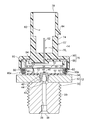
- FIG. 2 is a sectional view taken along line II-II.
- the pressure sensor 10 has a generally symmetric shape with respect to one axis (hereinafter referred to as a rotation axis A), and is integrally configured by engaging the body 12 and the output connector 14.
- the pressure sensor 10 is fixed to a common rail 16 (external object) that constitutes a part of a fuel injection system of an automobile.
- High pressure (generally on the order of 25 to 200 MPa) fuel is stored in the common rail 16.
- a threaded portion 20 that can be screwed with the screwing port 18 of the common rail 16 is formed on the outer peripheral wall on the front end side of the body 12.
- the electronic control unit acquires an output signal from the pressure sensor 10 and comprehensively controls each part including a fuel injection valve (not shown).
- the connection cable 24 is an electric wire for connecting the pressure sensor 10 to the ECU 22, and includes a cable line 26 and a cable connector 28.
- the cable connector 28 has three terminal receiving portions 28 a, 28 b, 28 c and is configured to be detachable from the output connector 14.
- the body 12 is integrally formed from a cylindrical joint portion 30, a flat pedestal portion 32, and a hollow cylindrical portion 34 in order from the lower side.
- the joint part 30, the pedestal part 32, and the cylindrical part 34 are made of a metal including, for example, a stainless steel material (SUS).
- Threaded portions 20 that can be screwed to the common rail 16 are formed on the outer peripheral wall of the joint portion 30.
- the joint portion 30 is formed with a hole-like introduction path 38 that gradually decreases in diameter from the introduction port 36 on the distal end side to the proximal end side through a stepped portion.
- the pedestal 32 has a hexagonal shape in plan view, and one hole 40 is formed at the center of gravity of the hexagon.
- a bottomed cylindrical stem 42 made of metal is inserted into the hole 40.
- the bottom portion of the stem 42 is in the form of a thin film, and functions as the diaphragm portion 46 by being deformed according to the pressure received from the main surface.
- a strain gauge 48 made of a conductor is disposed on the surface of the diaphragm portion 46 opposite to the pressure receiving surface.
- the strain gauge 48 constitutes a part of the bridge circuit and is connected to a circuit board 52 fixed on the accommodation surface 50 of the pedestal portion 32.
- the diaphragm portion 46, the strain gauge 48, and the circuit board 52 constitute a pressure detection portion 54 that acquires a detection signal corresponding to the fuel pressure from the introduction port 36.
- the cylindrical portion 34 is provided along a circumference having the center of gravity of the receiving surface 50 as the center point O1 (FIG. 3).
- the cylindrical portion 34 has two circumferential grooves 56 and 58 that are parallel to each other at the outer peripheral wall thereof. Two lower end bent portions 90e described later are engaged with the circumferential groove 56 on the lower stage side.
- an annular seal ring 60 made of, for example, resin is fitted into the upper circumferential groove 58.
- FIG. 3 is a plan view of the main part when the body 12 shown in FIG. 2 is viewed from the accommodation surface 50 side. This figure schematically shows the positional relationship between the pedestal portion 32 and the cylindrical portion 34.
- the cylindrical portion 34 further includes two projecting portions 62 and 62 (rotation restricting portions; illustrated by broken lines) projecting toward the space formed by the circumferential groove 56.
- the two protrusions 62 and 62 are arranged at positions symmetrical with respect to the center point O1 of the circumference.
- the output connector 14 includes three output terminals 70 formed by bending three strips into an L shape, and a housing 72 that accommodates the output terminals 70.
- the output terminal 70 is a highly conductive material, and is made of a metal or the like that has been plated.
- the housing 72 is mainly made of a resin containing polybutylene terephthalate (PBT).
- the three output terminals 70 are terminals for power supply, grounding, and signal output, respectively.
- the reference numeral (70) of the output terminal may be given a subscript to be distinguished from 70a, 70b, and 70c. The same applies to the tip 82 described later.
- the housing 72 has a bottomed cylindrical portion 74 that opens on one end side, and a bowl-shaped portion 76 that opens on the other end side.
- the bottomed cylindrical portion 74 has a space portion 80 that is largely opened at the opening portion 78 and that can accommodate the cable connector 28 (FIG. 1).
- the output terminal 70 is disposed such that the tip 82 projects toward the space 80. In other words, the opening 78 exposes the tip 82 of the output terminal 70 to the outside.
- FIG. 4 is a plan view of the output connector 14 shown in FIG. 2 viewed from the opening 78 side.
- the opening 78 has a double circular shape having a common center point O2. That is, the opening 78 has an “isotropic” shape that does not depend on the directions D1, D2, and D3 in plan view.
- each of the tip portions 82a to 82c has a rectangular shape in plan view, and is arranged in a line along the long side direction (direction D1). That is, the tip portions 82a to 82c have an “anisotropic” shape and an “anisotropic” arrangement depending on the directions D1 to D3 in plan view.
- the housing 72 further has a projecting portion 84 that travels outward on the outer peripheral wall of the bottomed cylindrical portion 74.
- the projecting portion 84 is disposed at a position along the short side direction (direction D3) of the distal end portion 82, starting from the center point O2.
- the pot-shaped portion 76 includes a cover 88 integrally formed with the bottomed tubular portion 74, and two attachment portions 90 and 90 fixed to the cover 88.
- Each attachment portion 90 has a substantially U-shaped cross-sectional shape, and is formed by subjecting one belt-like plate to bending twice.
- a portion bent at a right angle on the tip side of each attachment portion 90 is referred to as a tip bending portion 90e (second engagement portion).
- the two tip bent portions 90e, 90e are arranged along a circumference having substantially the same diameter as the cylindrical portion 34. That is, by arranging the body 12 and the output connector 14 coaxially, the two front bent portions 90 e and 90 e are simultaneously engaged with the circumferential groove 56.
- a space portion 92 surrounded by the pedestal portion 32 of the body 12, the cylindrical portion 34, and the bowl-shaped portion 76 of the housing 72 is formed.
- the space portion 92 accommodates a flexible flat harness 96 that connects the pressure detection portion 54 fixed to the body 12 to the output terminal 70 (base end portion 94) fixed to the housing 72.
- the high-pressure fuel is introduced into the pressure sensor 10 through the screw joint 18 (FIG. 1) and the inlet 36 of the common rail 16. This fuel is transferred to the diaphragm portion 46 side through the introduction path 38 and the internal space 44.
- the diaphragm portion 46 is deformed according to the pressure received from the fuel, and the strain gauge 48 is deformed following the shape of the diaphragm portion 46. Due to the difference in resistance value between the strain gauges 48, a signal (that is, a detection signal) correlated with the fuel pressure is generated by the circuit board 52. Thereafter, the generated detection signal is output to the outside of the pressure sensor 10 through the flexible flat harness 96 and the proximal end portion 94 and the distal end portion 82 of the output terminal 70.
- the mounting angle of the pressure sensor 10 with respect to the common rail 16 differs depending on the combination of the thread of the threaded portion 20 (or the thread groove of the screwing port 18).
- the output connector 14 is anisotropic in a plan view from the insertion direction B, an operator as a user is in a state where the orientation of the cable connector 28 is matched to the orientation of the output connector 14. It is necessary to insert the cable connector 28 into the cable.
- the output connector 14 is anisotropic means that the shape or arrangement of the distal end portion 82 and / or the shape of the opening 78 is anisotropic.
- the output connector 14 When the operator twists the bottomed cylindrical portion 74 clockwise or counterclockwise, the output connector 14 is rotated in the rotation direction C around the rotation axis A.
- the operator uses the position of the projecting portion 84 as a clue, aligns the output connector 14 with the cable connector 28 (see FIG. 5), and then inserts the cable connector 28 into the output connector 14 along the insertion direction B. To do.
- the tip end portion 82a is accommodated in the terminal receiving portion 28a
- the tip end portion 82b is accommodated in the terminal receiving portion 28b
- the tip end portion 82c is simultaneously accommodated in the terminal receiving portion 28c.
- the ECU 22 can acquire an output signal from the pressure sensor 10 through the connection cable 24.
- the operator may eliminate the twist of the cable wire 26 by rotating the bottomed tubular portion 74 with the cable connector 28 inserted.
- the pressure detection part 54 when the pressure detection part 54 is fixed to the body 12 and the base end part 94 is fixed to the housing 72, the pressure detection part 54 may be connected to the base end part 94 by a flexible flat harness 96.
- the flexible flat harness 96 that is robust against twisting, the rotation movable range of the output connector 14 can be expanded while maintaining the physical connection between the pressure detection unit 54 and the output terminal 70.
- one or more protrusions 62 may be provided in the circumferential groove 56 for restricting the rotational movable range of the output connector 14. Thereby, the electrical connection failure resulting from the excessive twist of the flexible flat harness 96 can be prevented.
- the rotation movable range is about 180 degrees (approximately ⁇ 90 degrees to +90 degrees).
- the body 12 or the housing 72 may be provided with a seal ring 60 that seals the space portion 92 surrounded by the body 12 and the housing 72 along the circumferential groove 58.
- a seal ring 60 that seals the space portion 92 surrounded by the body 12 and the housing 72 along the circumferential groove 58.
- the pressure sensor 10 includes the introduction port 36 for introducing the fuel stored in the common rail 16, the body 12 having the screw portion 20 that can be screwed to the common rail 16, and the introduction port 36.
- a pressure detector 54 for obtaining a detection signal corresponding to the pressure of the fuel, an output terminal 70 that can be connected to the cable connector 28 in a detachable manner and outputs a detection signal from the pressure detector 54 through the cable connector 28, and
- An output connector 14 having a housing 72 for accommodating the output terminal 70 is provided.
- the housing 72 has an opening 78 that exposes the distal end 82 of the output terminal 70 to the outside.
- the shape or arrangement of the distal end 82 and / or the shape of the opening 78 depends on the insertion direction B of the cable connector 28.
- the output connector 14 is configured to be rotatable about a rotation axis A along the insertion direction B with respect to the body 12.
- the output connector 14 is configured to be rotatable about the rotation axis A with respect to the body 12, the operator holds the cable connector 28 in a state where the cable wire 26 is not twisted.
- the cable connector 28 can be inserted into the output connector 14 after the output connector 14 is rotated in a direction in which both directions are matched. Thereby, even if it is the structure fixed by screwing, the connection in the state without the twist of the cable wire 26 is attained, As a result, the ease in which the cable wire 26 is settled can be maintained.
- the pressure sensor 10 measures the pressure of the fuel, but the whole fluid (liquid, gas or plasma) may be measured. Further, the pressure sensor 10 is screwed to the common rail 16, but any type of external object can be used as long as it is an external object capable of storing fluid therein.
- the front bent portion 90e is engaged with the circumferential groove 56, but the engagement structure of the body 12 and the output connector 14 is not limited to this.
- the body 12 includes a first engagement portion that is disposed along a circumference having the rotation axis A as an axis, and the housing 72 is disposed coaxially with the first engagement portion. Two engagement portions may be provided.
- two projecting portions 62 and 62 projecting toward the space formed by the circumferential groove 56 are provided, but means (rotation restricting portion) for restricting the rotational movable range of the output connector 14 is provided. It is not limited to this.
- the rotation restricting portion may be provided in the first engaging portion of the body 12, or may be provided in the second engaging portion of the housing 72 in addition to or separately from this.
Landscapes
- Physics & Mathematics (AREA)
- General Physics & Mathematics (AREA)
- Measuring Fluid Pressure (AREA)
Abstract
螺合により固定する構造であっても、ケーブル線の収まり易さを維持可能な圧力センサを提供する。 圧力センサ10は、ボディ12と出力コネクタ14を備える。出力コネクタ14のハウジング72は、出力端子70の先端部82を外部に露呈させる開口部78を有し、先端部82の形状若しくは配置、及び/又は開口部78の形状は、ケーブルコネクタ28の挿入方向Bからの平面視にて異方的である。そして、出力コネクタ14は、ボディ12に対して挿入方向Bに沿った回動軸Aを中心に回動可能に構成される。
Description
本発明は、流体の圧力に応じた検出信号を取得し、ケーブルコネクタを通じてこの検出信号を出力する圧力センサに関する。
従来から、流体の圧力に応じた検出信号を出力する圧力センサが開発されている。圧力センサは、例えば、自動車の燃料噴射システムにおいて、コモンレール内に流通する燃料の圧力を監視・制御するために使用される。この種のセンサは、内部の高圧力に耐えるため、コモンレールの螺合口に螺合させて固定する構造からなる(特許文献1参照)。
ところで、ねじ山(或いは、ねじ溝)の組み合わせによって、螺合口に対する圧力センサの取り付け角度が異なってくる。これにより、圧力センサに設けられた出力コネクタの向きにばらつきが生じる。
しかし、特許文献1に記載のセンサでは、ユーザは、ケーブルコネクタの向きを出力コネクタの向きに合わせた状態下に、ケーブルコネクタを出力コネクタに挿入する必要がある。その結果、ケーブルの捻れが発生し、ケーブル線の収まりが悪くなる懸念が生じる。
そこで、ケーブルの捻れを見越して配線スペースを予め確保することも想定されるが、その分だけ設計上の制約が生じてしまう。特に、複数本のケーブルを束ねてハーネス化した後、1つの電子制御ユニットに同時に接続する場合、上記した問題が顕在化する。
本発明は、上述した課題に鑑みてなされたものであり、螺合により固定する構造であっても、ケーブル線の収まり易さを維持可能な圧力センサを提供することを目的とする。
本発明に係る圧力センサは、外部物体の内部に蓄溜された流体を導入する導入口、及び、前記外部物体と螺合可能なネジ部を有するボディと、前記導入口からの前記流体の圧力に応じた検出信号を取得する圧力検出部と、ケーブルコネクタと挿抜自在に接続可能であり且つ該ケーブルコネクタを通じて前記圧力検出部からの前記検出信号を出力する出力端子、及び、前記出力端子を収容するハウジングを有する出力コネクタを備えるセンサであって、前記ハウジングは、前記出力端子の先端部を外部に露呈させる開口部を有し、前記先端部の形状若しくは配置、及び/又は前記開口部の形状は、前記ケーブルコネクタの挿入方向からの平面視にて異方的であり、前記出力コネクタは、前記ボディに対して前記挿入方向に沿った回動軸を中心に回動可能に構成される。
このように、出力コネクタは、ボディに対して挿入方向に沿った回動軸を中心に回動可能に構成されるので、ユーザは、例えば、ケーブルの捻れがない状態にてケーブルコネクタを把持し、両方の向きを合わせる方向に出力コネクタを回動させた後、ケーブルコネクタを出力コネクタに挿入できる。これにより、螺合により固定する構造であってもケーブルの捻れがない状態での接続が可能となり、その結果、ケーブル線の収まり易さを維持できる。
また、前記ボディは、前記回動軸を軸心とする円周に沿って配される第1係合部を更に有し、前記ハウジングは、前記第1係合部と同軸的に配される第2係合部を更に有し、前記出力コネクタは、前記第2係合部を前記第1係合部に係合させた状態下に、前記ボディに対して回動可能であることが好ましい。
また、前記圧力検出部は前記ボディに固定されると共に、前記出力端子の基端部は前記ハウジングに固定され、前記圧力検出部を前記基端部に接続する可撓性フラットハーネスを更に備えることが好ましい。捻れに対して頑健な可撓性フラットハーネスを用いることで、圧力検出部と出力端子の物理的な接続を維持しながら、出力コネクタの回動可動範囲を拡大できる。
また、前記第1係合部及び/又は前記第2係合部には、前記出力コネクタの回動可動範囲を規制する回動規制部が設けられることが好ましい。これにより、可撓性フラットハーネスの過度の捻れに起因する電気的な接続不良を防止できる。
また、前記第2係合部を前記第1係合部に係合させることで、前記ボディ及び前記ハウジングに囲まれた空間部が形成され、前記ボディ又は前記ハウジングには、前記空間部を密封するシールリングが前記円周に沿って設けられることが好ましい。ボディ又はハウジングにシールリングを設けることで、空間部の気密性が一層高くなる。
また、前記外部物体は、燃料噴射システムの一部を構成するコモンレールであり、前記流体は、前記コモンレールの内部に蓄溜された燃料であることが好ましい。
本発明に係る圧力センサによれば、螺合により固定する構造であっても、ケーブル線の収まり易さを維持できる。
以下、本発明に係る圧力センサにおいて好適な実施形態を挙げ、添付の図面を参照しながら説明する。
[圧力センサ10の構成]
図1は、この実施形態に係る圧力センサ10の斜視図である。図2は、II-II線に沿った断面図である。
図1は、この実施形態に係る圧力センサ10の斜視図である。図2は、II-II線に沿った断面図である。
圧力センサ10は、一軸(以下、回動軸A)に関して概ね対称的な形状を有し、ボディ12及び出力コネクタ14が係合して一体的に構成される。本図例では、圧力センサ10は、自動車の燃料噴射システムの一部を構成するコモンレール16(外部物体)に固定される。コモンレール16の内部には、高圧力(概ね25~200MPaオーダ)の燃料が蓄溜されている。ボディ12の先端側外周壁には、コモンレール16の螺合口18と螺合可能なネジ部20が形成されている。
電子制御ユニット(以下、ECU22)は、圧力センサ10からの出力信号を取得し、図示しない燃料噴射弁を含む各部を統括的に制御する。接続ケーブル24は、圧力センサ10をECU22に接続するための電線であり、ケーブル線26及びケーブルコネクタ28を有する。ケーブルコネクタ28は、3つの端子受け部28a、28b、28cを有すると共に、出力コネクタ14に対して着脱可能に構成される。
図2に示すように、ボディ12は、下側から順に、筒状の継手部30と、平板状の台座部32と、中空円筒状の円筒部34とから一体的に構成される。継手部30、台座部32及び円筒部34は、例えば、ステンレス鋼材(SUS)を含む金属からなる。
継手部30の外周壁には、コモンレール16(図1)と螺合可能なネジ部20が形成されている。継手部30には、先端側の導入口36から基端側にかけて、段部を介して徐々に縮径する孔状の導入路38が形成されている。
台座部32は、平面視にて六角形状を有し、当該六角形の重心位置には1つの孔部40が形成されている。孔部40には、金属からなる有底筒状のステム42が介挿されている。ステム42の内部空間44が導入路38に連通することで、導入口36を始端としステム42の底部を終端とする一連の圧力導入路が形成される。ステム42の底部は薄膜状であり、主面からの受圧に応じて変形することでダイヤフラム部46として機能する。
ダイヤフラム部46の受圧面とは反対面の上には、導体からなる歪みゲージ48が配置されている。歪みゲージ48は、ブリッジ回路の一部を構成すると共に、台座部32の収容面50上に固定された回路基板52に接続されている。ここで、ダイヤフラム部46、歪みゲージ48及び回路基板52は、導入口36からの燃料の圧力に応じた検出信号を取得する圧力検出部54を構成する。
円筒部34は、収容面50の重心を中心点O1(図3)とする円周に沿って設けられている。円筒部34は、その外周壁にて互いに平行する2つの円周溝56、58を有する。下段側の円周溝56には、後述する2つの先端折曲部90eが係合されている。一方、上段側の円周溝58には、例えば樹脂からなる環状のシールリング60が嵌合されている。
図3は、図2に示すボディ12を収容面50側から視た要部平面図である。本図は、台座部32と円筒部34の間の位置関係を模式的に示している。円筒部34は、円周溝56がなす空間に向けて突出する2つの突出部62、62(回動規制部;破線で図示)を更に有する。2つの突出部62、62は、円周の中心点O1に関して対称な位置に配されている。
図2に戻って、出力コネクタ14は、3枚の帯状板をL字状に屈曲させてなる3つの出力端子70と、出力端子70を収容するハウジング72とを含んで構成される。出力端子70は、導電性が高い材料であり、めっき処理が施された金属等からなる。ハウジング72は、主に、ポリブチレンテレフタラート(PBT)を含む樹脂からなる。
3つの出力端子70はそれぞれ、電源用、接地用及び信号出力用の端子である。以下、出力端子の参照数字(70)に添字を付与し、70a、70b、70cと区別して表記する場合がある。また、後述する先端部82についても同様である。
ハウジング72は、一端側にて開口する有底筒状部74と、他端側にて開口する鉢状部76とを有する。有底筒状部74は、開口部78にて大きく開口すると共に、ケーブルコネクタ28(図1)を収容可能な空間部80を有する。出力端子70は、先端部82が空間部80に向けて突出するように配置される。換言すれば、開口部78は、出力端子70の先端部82を外部に露呈させている。
図4は、図2に示す出力コネクタ14を開口部78側から視た平面図である。開口部78は、共通の中心点O2を有する二重円の形状を有する。つまり、開口部78は、平面視にて方向D1、D2、D3に依存しない「等方的」な形状である。一方、先端部82a~82cはいずれも平面視形状が長方形であり、且つ、長辺方向(方向D1)に沿って一列に並んで配置されている。つまり、先端部82a~82cは、平面視にて方向D1~D3に依存する「異方的」な形状であると共に「異方的」な配置である。
また、ハウジング72は、有底筒状部74の外周壁にて外方に出張った出張り部84を更に有する。出張り部84は、中心点O2を起点として、先端部82の短辺方向(方向D3)に沿った位置に配されている。
図2に戻って、鉢状部76は、有底筒状部74と一体成形されたカバー88と、カバー88に固定された2つの取り付け部90、90とを有する。各取り付け部90は、断面形状が概略コ字状(U字状)であり、1枚の帯状板に対して2回の折曲加工を施すことで形成される。ここで、各取り付け部90の先端側にて直角に折り曲げた部位を、先端折曲部90e(第2係合部)と称する。2つの先端折曲部90e、90eは、円筒部34と略同一の直径を有する円周に沿って配されている。すなわち、ボディ12と出力コネクタ14を同軸的に配することで、2つの先端折曲部90e、90eは円周溝56に同時に係合される。
この係合によって、ボディ12の台座部32、円筒部34、並びにハウジング72の鉢状部76に囲まれた空間部92が形成される。空間部92には、ボディ12に固定された圧力検出部54を、ハウジング72に固定された出力端子70(基端部94)に接続する可撓性フラットハーネス96が収容されている。
[圧力センサ10の動作]
この実施形態に係る圧力センサ10は以上のように構成される。続いて、圧力センサ10の動作について、図2~図4を参照しながら説明する。
この実施形態に係る圧力センサ10は以上のように構成される。続いて、圧力センサ10の動作について、図2~図4を参照しながら説明する。
図2に示すように、高圧力の燃料は、コモンレール16の螺合口18(図1)及び導入口36を通じて、圧力センサ10の内部に導入される。この燃料は、導入路38及び内部空間44を通じてダイヤフラム部46側に移送される。ダイヤフラム部46は燃料からの受圧に応じて変形されると共に、歪みゲージ48はダイヤフラム部46の形状に倣って変形される。歪みゲージ48の間における抵抗値の差が生じることで、回路基板52により燃料の圧力に相関する信号(すなわち、検出信号)が生成される。その後、生成された検出信号は、可撓性フラットハーネス96、出力端子70の基端部94及び先端部82を通じて、圧力センサ10の外部に出力される。
ところで、ネジ部20のねじ山(或いは、螺合口18のねじ溝)の組み合わせによって、コモンレール16に対する圧力センサ10の取り付け角度が異なってくる。図1に例示するように、挿入方向Bから平面視にて出力コネクタ14が異方的である場合、ユーザとしての作業者は、ケーブルコネクタ28の向きを出力コネクタ14の向きに合わせた状態下にケーブルコネクタ28を挿入する必要がある。ここで、「出力コネクタ14が異方的」とは、先端部82の形状若しくは配置、及び/又は開口部78の形状が異方的であることを意味する。
作業者が時計回り又は反時計回りに有底筒状部74を捻ると、出力コネクタ14は、回動軸Aを中心とする回動方向Cに回動される。作業者は、出張り部84の位置を手掛かりにし、出力コネクタ14の向きをケーブルコネクタ28の向きに合わせた後(図5参照)、挿入方向Bに沿ってケーブルコネクタ28を出力コネクタ14に挿入する。
そうすると、先端部82aは端子受け部28aに、先端部82bが端子受け部28bに、先端部82cは端子受け部28cに同時に収容される。これにより、ECU22は、接続ケーブル24を通じて圧力センサ10からの出力信号を取得できる。
或いは、作業者は、ケーブルコネクタ28を挿入した状態下にて有底筒状部74を回動させることで、ケーブル線26の捻れを解消してもよいことは言うまでもない。
ところで、圧力検出部54はボディ12に、基端部94はハウジング72にそれぞれ固定されている場合、可撓性フラットハーネス96によって圧力検出部54を基端部94に接続してもよい。捻れに対して頑健な可撓性フラットハーネス96を用いることで、圧力検出部54と出力端子70の物理的な接続を維持しながら、出力コネクタ14の回動可動範囲を拡大できる。
また、出力コネクタ14の回動可動範囲を規制する突出部62を円周溝56に1つ以上(図3例では2つ)設けてもよい。これにより、可撓性フラットハーネス96の過度の捻れに起因する電気的な接続不良を防止できる。なお、図3例では、回動可動範囲が180度程度(概ね-90度から+90度)とされている。
また、ボディ12又はハウジング72(図2例ではボディ12)には、ボディ12及びハウジング72に囲まれた空間部92を密封するシールリング60を円周溝58に沿って設けてもよい。ボディ12又はハウジング72の係合部位又はその周辺部位にシールリング60を設けることで、空間部92の気密性が一層高くなる。
[圧力センサ10による効果]
以上のように、圧力センサ10は、コモンレール16の内部に蓄溜された燃料を導入する導入口36、及び、コモンレール16と螺合可能なネジ部20を有するボディ12と、導入口36からの燃料の圧力に応じた検出信号を取得する圧力検出部54と、ケーブルコネクタ28と挿抜自在に接続可能であり且つケーブルコネクタ28を通じて圧力検出部54からの検出信号を出力する出力端子70、及び、出力端子70を収容するハウジング72を有する出力コネクタ14を備える。
以上のように、圧力センサ10は、コモンレール16の内部に蓄溜された燃料を導入する導入口36、及び、コモンレール16と螺合可能なネジ部20を有するボディ12と、導入口36からの燃料の圧力に応じた検出信号を取得する圧力検出部54と、ケーブルコネクタ28と挿抜自在に接続可能であり且つケーブルコネクタ28を通じて圧力検出部54からの検出信号を出力する出力端子70、及び、出力端子70を収容するハウジング72を有する出力コネクタ14を備える。
そして、ハウジング72は、出力端子70の先端部82を外部に露呈させる開口部78を有し、先端部82の形状若しくは配置、及び/又は開口部78の形状は、ケーブルコネクタ28の挿入方向Bからの平面視にて異方的であり、出力コネクタ14は、ボディ12に対して挿入方向Bに沿った回動軸Aを中心に回動可能に構成される。
このように、出力コネクタ14は、ボディ12に対して回動軸Aを中心に回動可能に構成されるので、作業者は、ケーブル線26の捻れがない状態にてケーブルコネクタ28を把持し、両方の向きを合わせる方向に出力コネクタ14を回動させた後、ケーブルコネクタ28を出力コネクタ14に挿入できる。これにより、螺合により固定する構造であってもケーブル線26の捻れがない状態での接続が可能となり、その結果、ケーブル線26の収まり易さを維持できる。
[備考]
なお、この発明は、上述した実施形態に限定されるものではなく、この発明の主旨を逸脱しない範囲で自由に変更できることは勿論である。
なお、この発明は、上述した実施形態に限定されるものではなく、この発明の主旨を逸脱しない範囲で自由に変更できることは勿論である。
この実施形態では、圧力センサ10は燃料の圧力を測定しているが、流体全般(液体、気体又はプラズマ)を測定対象としてもよい。また、圧力センサ10はコモンレール16に螺合されているが、内部に流体を蓄溜可能な外部物体であれば種類を問わない。
この実施形態では、先端折曲部90eを円周溝56に係合させているが、ボディ12及び出力コネクタ14の係合構造はこれに限られない。例えば、ボディ12は、回動軸Aを軸心とする円周に沿って配される第1係合部を備えると共に、ハウジング72は、この第1係合部と同軸的に配される第2係合部を備えてもよい。
この実施形態では、円周溝56がなす空間に向けて突出する2つの突出部62、62が設けられているが、出力コネクタ14の回動可動範囲を規制する手段(回動規制部)はこれに限られない。例えば、回動規制部をボディ12の第1係合部に設けてもよいし、これと併せて又はこれとは別に、ハウジング72の第2係合部に設けてもよい。
Claims (6)
- 外部物体の内部に蓄溜された流体を導入する導入口、及び、前記外部物体と螺合可能なネジ部を有するボディと、
前記導入口からの前記流体の圧力に応じた検出信号を取得する圧力検出部と、
ケーブルコネクタと挿抜自在に接続可能であり且つ該ケーブルコネクタを通じて前記圧力検出部からの前記検出信号を出力する出力端子、及び、前記出力端子を収容するハウジングを有する出力コネクタと
を備える圧力センサであって、
前記ハウジングは、前記出力端子の先端部を外部に露呈させる開口部を有し、
前記先端部の形状若しくは配置、及び/又は前記開口部の形状は、前記ケーブルコネクタの挿入方向からの平面視にて異方的であり、
前記出力コネクタは、前記ボディに対して前記挿入方向に沿った回動軸を中心に回動可能に構成される
ことを特徴とする圧力センサ。 - 前記ボディは、前記回動軸を軸心とする円周に沿って配される第1係合部を更に有し、
前記ハウジングは、前記第1係合部と同軸的に配される第2係合部を更に有し、
前記出力コネクタは、前記第2係合部を前記第1係合部に係合させた状態下に、前記ボディに対して回動可能である
ことを特徴とする請求項1に記載の圧力センサ。 - 前記圧力検出部は前記ボディに固定されると共に、前記出力端子の基端部は前記ハウジングに固定され、
前記圧力検出部を前記基端部に接続する可撓性フラットハーネスを更に備える
ことを特徴とする請求項2に記載の圧力センサ。 - 前記第1係合部及び/又は前記第2係合部には、前記出力コネクタの回動可動範囲を規制する回動規制部が設けられることを特徴とする請求項3に記載の圧力センサ。
- 前記第2係合部を前記第1係合部に係合させることで、前記ボディ及び前記ハウジングに囲まれた空間部が形成され、
前記ボディ又は前記ハウジングには、前記空間部を密封するシールリングが前記円周に沿って設けられる
ことを特徴とする請求項2~4のいずれか1項に記載の圧力センサ。 - 前記外部物体は、燃料噴射システムの一部を構成するコモンレールであり、
前記流体は、前記コモンレールの内部に蓄溜された燃料である
ことを特徴とする請求項1~5のいずれか1項に記載の圧力センサ。
Priority Applications (1)
| Application Number | Priority Date | Filing Date | Title |
|---|---|---|---|
| JP2016566085A JP6153280B2 (ja) | 2014-12-25 | 2015-12-04 | 圧力センサ |
Applications Claiming Priority (2)
| Application Number | Priority Date | Filing Date | Title |
|---|---|---|---|
| JP2014262739 | 2014-12-25 | ||
| JP2014-262739 | 2014-12-25 |
Publications (1)
| Publication Number | Publication Date |
|---|---|
| WO2016104109A1 true WO2016104109A1 (ja) | 2016-06-30 |
Family
ID=56150139
Family Applications (1)
| Application Number | Title | Priority Date | Filing Date |
|---|---|---|---|
| PCT/JP2015/084129 Ceased WO2016104109A1 (ja) | 2014-12-25 | 2015-12-04 | 圧力センサ |
Country Status (2)
| Country | Link |
|---|---|
| JP (1) | JP6153280B2 (ja) |
| WO (1) | WO2016104109A1 (ja) |
Families Citing this family (1)
| Publication number | Priority date | Publication date | Assignee | Title |
|---|---|---|---|---|
| JP6692698B2 (ja) * | 2016-05-26 | 2020-05-13 | ボッシュ株式会社 | 圧力センサ |
Citations (2)
| Publication number | Priority date | Publication date | Assignee | Title |
|---|---|---|---|---|
| JP5500112B2 (ja) * | 2011-04-01 | 2014-05-21 | 株式会社デンソー | センサ装置 |
| JP2014238365A (ja) * | 2013-06-10 | 2014-12-18 | 長野計器株式会社 | センサ |
-
2015
- 2015-12-04 JP JP2016566085A patent/JP6153280B2/ja not_active Expired - Fee Related
- 2015-12-04 WO PCT/JP2015/084129 patent/WO2016104109A1/ja not_active Ceased
Patent Citations (2)
| Publication number | Priority date | Publication date | Assignee | Title |
|---|---|---|---|---|
| JP5500112B2 (ja) * | 2011-04-01 | 2014-05-21 | 株式会社デンソー | センサ装置 |
| JP2014238365A (ja) * | 2013-06-10 | 2014-12-18 | 長野計器株式会社 | センサ |
Also Published As
| Publication number | Publication date |
|---|---|
| JP6153280B2 (ja) | 2017-06-28 |
| JPWO2016104109A1 (ja) | 2017-06-22 |
Similar Documents
| Publication | Publication Date | Title |
|---|---|---|
| US20130249534A1 (en) | Measuring device | |
| KR102673496B1 (ko) | 물리량 측정 장치 | |
| JP2019537475A (ja) | 流体導通ライン間の流体接続を確立するための接続部品およびこのタイプの接続部品を備える医療機器 | |
| JP2008215609A (ja) | クイックコネクタ | |
| US8111167B2 (en) | Level indicator and process for assembling a level indicator | |
| EP2927657B1 (en) | Fluid pressure measuring device and method of manufacturing the same | |
| JP6655866B2 (ja) | 基準尺を走査する走査ユニットと位置測定装置 | |
| CN104541137A (zh) | 用于加压或液化气体的容器的电容式液位计组件 | |
| JP6153280B2 (ja) | 圧力センサ | |
| CA2957227C (en) | Rotatable and removable multi-pin explosion proof connector assembly | |
| US20240219253A1 (en) | Adaptation Device for Coupling at least One Sensor to a Tube Shell Wall of a Tube for Fluid Measurement, and Sensor Device Having an Adaptation Device of this Type | |
| JPH01102317A (ja) | センサ | |
| US10048149B2 (en) | Relative pressure sensor | |
| LU93059B1 (en) | Gas cylinder valve with a connected sensing unit | |
| US9048562B2 (en) | Contacting system for producing electrical contact between a cable and a sensor | |
| JP5970167B2 (ja) | 高圧蒸気滅菌装置 | |
| CN104653364A (zh) | 导线密封组件 | |
| US7513162B2 (en) | Vibration sensor or measurement detector | |
| EP4735783A1 (en) | Sensor connector with bayonet coupling | |
| JP2008004297A (ja) | 防水型コネクタ | |
| CN206583929U (zh) | 加速度传感器组装体 | |
| JP6340890B2 (ja) | 水位検知装置 | |
| CN114526776B (zh) | 现场设备壳体以及现场设备 | |
| JP2010232130A (ja) | コネクタ付き蓋の接続構造 | |
| JP7056331B2 (ja) | 液質検出器及び液質分析システム |
Legal Events
| Date | Code | Title | Description |
|---|---|---|---|
| 121 | Ep: the epo has been informed by wipo that ep was designated in this application |
Ref document number: 15872678 Country of ref document: EP Kind code of ref document: A1 |
|
| ENP | Entry into the national phase |
Ref document number: 2016566085 Country of ref document: JP Kind code of ref document: A |
|
| NENP | Non-entry into the national phase |
Ref country code: DE |
|
| 122 | Ep: pct application non-entry in european phase |
Ref document number: 15872678 Country of ref document: EP Kind code of ref document: A1 |